sx440 automatic voltage regulator (avr) - Frontier Power Products
sx440 automatic voltage regulator (avr) - Frontier Power Products
sx440 automatic voltage regulator (avr) - Frontier Power Products

Create successful ePaper yourself
Turn your PDF publications into a flip-book with our unique Google optimized e-Paper software.
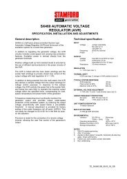
FITTING AND OPERATING<br />
STABILITY ADJUSTMENT<br />
The AVR includes a stability or damping circuit to provide<br />
good steady state and transient performance of the<br />
generator.<br />
The correct setting can be found by running the generator<br />
at no load and slowly turning the stability control anticlockwise<br />
until the generator <strong>voltage</strong> starts to become<br />
unstable.<br />
The optimum or critically damped position is slightly<br />
clockwise from this point (i.e. where the machine volts are<br />
stable but close to the unstable region).<br />
OPTIMUM RESPONSE SELECTION<br />
The stability selection ‘jumper’ should be correctly linked,<br />
A-B, B-C or A-C at the bottom of the board for the frame<br />
size of the generator, (see drawing).<br />
UNDER FREQUENCY ROLL OFF (UFRO)<br />
ADJUSTMENT<br />
TRIM ADJUSTMENT<br />
An analogue input (A1 A2) is provided to connect to the<br />
Newage <strong>Power</strong> Factor Controller or other devices. It is<br />
designed to accept dc signals up to +/- 5 volts.<br />
CAUTION Any devices connected to this input must be<br />
fully floating and galvanically isolated from ground, with<br />
an insulation capability of 500 Vac. Failure to observe<br />
this could result in equipment damage.<br />
The dc signal applied to this input adds to the AVR<br />
sensing circuit. A1 is connected to the AVR 0 volts.<br />
Positive on A2 increases excitation. Negative on A2<br />
decreases excitation.<br />
The TRIM control allows the user to adjust the<br />
sensitivity of the input. With TRIM fully anti-clockwise<br />
the externally applied signal has no effect. Clockwise it<br />
has maximum effect.<br />
Normal setting is fully clockwise when used with a<br />
Newage <strong>Power</strong> Factor Controller.<br />
The AVR incorporates an underspeed protection circuit<br />
which gives a volts/Hz characteristic when the generator<br />
speed falls below a presettable threshold known as the<br />
"knee" point.<br />
The red Light Emitting Diode (LED) gives indication that<br />
the UFRO circuit is operating.<br />
The UFRO adjustment is preset and sealed and only<br />
requires the selection of 50 / 60Hz using the jumper link.<br />
For optimum setting, the LED should illuminate as the<br />
frequency falls just below nominal, i.e. 47Hz on a 50Hz<br />
system or 57Hz on a 60Hz system.<br />
DROOP ADJUSTMENT<br />
Generators intended for parallel operation are fitted with a<br />
quadrature droop C.T. which provides a power factor<br />
dependent signal for the AVR. The C.T. is connected to<br />
S1, S2 on the AVR.<br />
The DROOP adjustment is normally preset in the works<br />
to give 5% <strong>voltage</strong> droop at full load zero power factor.<br />
Clockwise increases the amount of C.T. signal injected<br />
into the AVR and increases the droop with lagging power<br />
factor (cos Ø). With the control fully anti-clockwise there<br />
is no droop.<br />
© 2003 Newage International Limited.<br />
Reprinted with permission of N.I. only.<br />
Printed in England.<br />
PO Box 17 • Barnack Road • Stamford • Lincolnshire • PE9 2NB<br />
Tel: 00 44 (0)1780 484000 • Fax: 00 44 (0)1780 484100<br />
Website: www.newage-avkseg.com<br />
TD_SX440.GB_05.03_02