sx440 automatic voltage regulator (avr) - Frontier Power Products
sx440 automatic voltage regulator (avr) - Frontier Power Products
sx440 automatic voltage regulator (avr) - Frontier Power Products

Create successful ePaper yourself
Turn your PDF publications into a flip-book with our unique Google optimized e-Paper software.
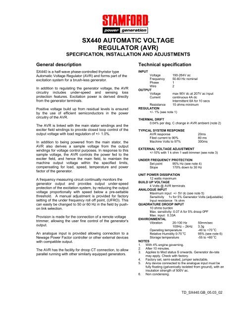
DESIGN DETAIL<br />
SX440 AUTOMATIC VOLTAGE<br />
REGULATOR (AVR)<br />
SPECIFICATION, INSTALLATION AND ADJUSTMENTS<br />
General description<br />
SX440 is a half-wave phase-controlled thyristor type<br />
Automatic Voltage Regulator (AVR) and forms part of the<br />
excitation system for a brush-less generator.<br />
In addition to regulating the generator <strong>voltage</strong>, the AVR<br />
circuitry includes under-speed and sensing loss<br />
protection features. Excitation power is derived directly<br />
from the generator terminals.<br />
Positive <strong>voltage</strong> build up from residual levels is ensured<br />
by the use of efficient semiconductors in the power<br />
circuitry of the AVR.<br />
The AVR is linked with the main stator windings and the<br />
exciter field windings to provide closed loop control of the<br />
output <strong>voltage</strong> with load regulation of +/- 1.0%.<br />
In addition to being powered from the main stator, the<br />
AVR also derives a sample <strong>voltage</strong> from the output<br />
windings for <strong>voltage</strong> control purposes. In response to this<br />
sample <strong>voltage</strong>, the AVR controls the power fed to the<br />
exciter field, and hence the main field, to maintain the<br />
machine output <strong>voltage</strong> within the specified limits,<br />
compensating for load, speed, temperature and power<br />
factor of the generator.<br />
A frequency measuring circuit continually monitors the<br />
generator output and provides output under-speed<br />
protection of the excitation system, by reducing the output<br />
<strong>voltage</strong> proportionally with speed below a pre-settable<br />
threshold. A manual adjustment is provided for factory<br />
setting of the under frequency roll off point, (UFRO). This<br />
can easily be changed to 50 or 60 Hz in the field by pushon<br />
link selection.<br />
Provision is made for the connection of a remote <strong>voltage</strong><br />
trimmer, allowing the user fine control of the generator's<br />
output.<br />
An analogue input is provided allowing connection to a<br />
Newage <strong>Power</strong> Factor controller or other external devices<br />
with compatible output.<br />
The AVR has the facility for droop CT connection, to allow<br />
parallel running with other similarly equipped generators.<br />
Technical specification<br />
INPUT<br />
Voltage 190-264V ac<br />
Frequency 50-60 Hz nominal<br />
Phase 1<br />
Wire 2<br />
OUTPUT<br />
Voltage max 90V dc at 207V ac input<br />
Current continuous 4A dc<br />
Intermittent 6A for 10 secs<br />
Resistance 15 ohms minimum<br />
REGULATION<br />
+/- 1% (see note 1)<br />
THERMAL DRIFT<br />
0.04% per deg. C change in AVR ambient (note 2)<br />
TYPICAL SYSTEM RESPONSE<br />
AVR response<br />
Filed current to 90%<br />
Machine Volts to 97%<br />
20ms<br />
80 ms<br />
300ms<br />
EXTERNAL VOLTAGE ADJUSTMENT<br />
+/-10% with 1 k ohm 1 watt trimmer (see note 3)<br />
UNDER FREQUENCY PROTECTION<br />
Set point 95% Hz (see note 4)<br />
Slope 170% down to 30 Hz<br />
UNIT POWER DISSIPATION<br />
12 watts maximum<br />
BUILD UP VOLTAGE<br />
4 Volts @ AVR terminals<br />
ANALOGUE INPUT<br />
Maximum input +/- 5V dc (see note 5)<br />
Sensitivity 1v for 5% Generator Volts (adjustable)<br />
Input resistance 1k ohm<br />
QUADRATURE DROOP INPUT<br />
10 ohms burden<br />
Max. sensitivity: 0.07 A for 5% droop 0PF<br />
Max. input: 0.33A<br />
ENVIRONMENTAL<br />
Vibration 20-100 Hz 50mm/sec<br />
100Hz – 2kHz 3.3g<br />
Operating temperature<br />
-40 to +70 o C<br />
Relative Humidity 0-70 o C 95% (see note 6)<br />
Storage temperature<br />
-55 to +80 o C<br />
NOTES<br />
1. With 4% engine governing.<br />
2. After 10 minutes.<br />
3. Applies to Mod status S onwards. Generator de-rate<br />
may apply. Check with factory.<br />
4. Factory set, semi-sealed, jumper selectable.<br />
5. Any device connected to the analogue input must be<br />
fully floating (galvanically isolated from ground), with an<br />
insulation strength of 500V ac.<br />
6. Non condensing.<br />
TD_SX440.GB_05.03_02
DESIGN DETAIL<br />
Voltage<br />
Sensing<br />
Generator<br />
Droop<br />
Hand<br />
Trimmer<br />
Potential<br />
Divider &<br />
Rectifier<br />
Suppression<br />
Sensing<br />
Loss<br />
Detector<br />
Low Hz<br />
Detection<br />
Reference<br />
Voltage<br />
Synchronising<br />
Circuit<br />
Low Pass<br />
Filter<br />
<strong>Power</strong><br />
supply<br />
Analogue<br />
Input<br />
DC<br />
Mixer<br />
Amp<br />
Ramp<br />
Generator<br />
Level<br />
Detector &<br />
Driver<br />
<strong>Power</strong><br />
Control<br />
Devices<br />
Stability<br />
Circuit<br />
Exciter<br />
Field<br />
The main functions of the AVR are:<br />
Potential Divider and Rectifier takes a proportion of the<br />
generator output <strong>voltage</strong> and attenuates it. The potential<br />
divider is adjustable by the AVR Volts potentiometer and<br />
external hand trimmer (when fitted). The output from the<br />
droop CT is also added to this signal. An isolating<br />
transformer is included allowing connection to various<br />
winding configurations. A rectifier converts the a.c. input<br />
signal into d.c. for further processing.<br />
The Sensing Loss Detector is an electronic changeover<br />
switch, which normally connects the Amplifier (Amp) to<br />
the Voltage Sensing input and <strong>automatic</strong>ally changes<br />
over to the <strong>Power</strong> input when the normal sensing <strong>voltage</strong><br />
is lost.<br />
The DC Mixer adds the Analogue input signal the<br />
Sensing signal.<br />
The Amplifier (Amp) compares the sensing <strong>voltage</strong> to the<br />
Reference Voltage and amplifies the difference (error) to<br />
provide a controlling signal for the power devices. The<br />
Ramp Generator and Level Detector and Driver infinitely<br />
control the conduction period of the <strong>Power</strong> Control<br />
Devices and hence provides the excitation system with<br />
the required power to maintain the generator <strong>voltage</strong><br />
within specified limits.<br />
The Stability Circuit provides adjustable negative ac<br />
feedback to ensure good steady state and transient<br />
performance of the control system.<br />
The Low Hz Detector measures the period of each<br />
electrical cycle and causes the reference <strong>voltage</strong> to<br />
be reduced approximately linearly with speed below<br />
a presettable threshold. A Light Emitting Diode gives<br />
indication of underspeed running.<br />
The Synchronising circuit is used to keep the Ramp<br />
Generator and Low Hz Detector locked to the<br />
generator waveform period.<br />
The Low Pass Filter prevents distorted waveforms<br />
affecting the operation of the AVR control circiut<br />
<strong>Power</strong> Control Devices vary the amount of exciter<br />
field current in response to the error signal produced<br />
by the Amplifier.<br />
Suppression components are included to prevent<br />
sub cycle <strong>voltage</strong> spikes damaging the AVR<br />
components and also to reduce the amount of<br />
conducted noise on the generator terminals..<br />
The <strong>Power</strong> Supply provides the required <strong>voltage</strong>s<br />
for the AVR circuitry.<br />
TD_SX440.GB_05.03_02
FITTING AND OPERATING<br />
K1 K2 P2 P3 P4 XX X 3 2 2 1<br />
K1-K2<br />
<strong>Power</strong> isolation link<br />
(normally fitted)<br />
Trim<br />
Droop<br />
A1<br />
A2<br />
S1<br />
S2<br />
REFER TO GENERATOR WIRING DIAGRAM<br />
FOR CONNECTION DETAILS<br />
Indicator<br />
LED<br />
UFRO<br />
Frequency<br />
Selection<br />
50 C 60<br />
SX440<br />
50Hz<br />
60Hz<br />
Stability<br />
Volts<br />
Stability<br />
Selection<br />
1<br />
2<br />
3<br />
4<br />
5<br />
6<br />
7<br />
8<br />
> 550kW<br />
90-550kW<br />
< 90kW<br />
C B A<br />
Sensing<br />
links<br />
standard<br />
positions<br />
SUMMARY OF AVR CONTROLS<br />
CONTROL FUNCTION DIRECTION<br />
VOLTS TO ADJUST GENERATOR OUTPUT VOLTAGE CLOCKWISE INCREASES OUTPUT VOLTAGE<br />
STABILITY TO PREVENT VOLTAGE HUNTING CLOCKWISE INCREASE THE DAMPING EFFECT<br />
UFRO TO SET THE UFRO KNEE POINT CLOCKWISE REDUCES THE KNEE POINT<br />
DROOP TO SET THE GENERATOR DROOP TO 5% AT 0PF FREQUENCY<br />
CLOCKWISE INCREASES THE DROOP<br />
VTRIM TO OPTIMISE ANALOGUE INPUT SENSITIVITY CLOCKWISE INCREASES THE GAIN OR SENSITIVITY<br />
ADJUSTMENT OF AVR CONTROLS<br />
VOLTAGE ADJUSTMENT<br />
The generator output <strong>voltage</strong> is set at the factory, but can<br />
be altered by careful adjustment of the VOLTS control on<br />
the AVR board, or by the external hand trimmer if fitted.<br />
Terminals 1 and 2 on the AVR will be fitted with a shorting<br />
link if no hand trimmer is required.<br />
CAUTION Do not increase the <strong>voltage</strong> above the rated<br />
generator <strong>voltage</strong>. If in doubt, refer to the rating plate<br />
mounted on the generator case.<br />
CAUTION Do not ground any of the hand trimmer<br />
terminals as these could be above earth potential. Failure<br />
to observe this could cause equipment damage.<br />
If a replacement AVR has been fitted or re-setting of the<br />
VOLTS adjustment is required, proceed as follows:<br />
CAUTION<br />
1. Before running generator, turn the VOLTS control<br />
fully anti-clockwise.<br />
2. Turn remote volts trimmer (if fitted) to midway<br />
position.<br />
3. Turn STABILITY control to midway position.<br />
4. Connect a suitable voltmeter (0-300V ac) across<br />
line to neutral of the generator.<br />
5. Start generator set, and run on no load at nominal<br />
frequency e.g. 50-53Hz or 60-63Hz.<br />
6. If the red Light Emitting Diode (LED) is illuminated,<br />
refer to the Under Frequency Roll Off (UFRO)<br />
adjustment.<br />
7. Carefully turn VOLTS control clockwise until rated<br />
<strong>voltage</strong> is reached.<br />
8. If instability is present at rated <strong>voltage</strong>, refer to<br />
stability adjustment, then re-adjust <strong>voltage</strong> if<br />
necessary.<br />
9. Voltage adjustment is now completed.<br />
TD_SX440.GB_05.03_02
FITTING AND OPERATING<br />
STABILITY ADJUSTMENT<br />
The AVR includes a stability or damping circuit to provide<br />
good steady state and transient performance of the<br />
generator.<br />
The correct setting can be found by running the generator<br />
at no load and slowly turning the stability control anticlockwise<br />
until the generator <strong>voltage</strong> starts to become<br />
unstable.<br />
The optimum or critically damped position is slightly<br />
clockwise from this point (i.e. where the machine volts are<br />
stable but close to the unstable region).<br />
OPTIMUM RESPONSE SELECTION<br />
The stability selection ‘jumper’ should be correctly linked,<br />
A-B, B-C or A-C at the bottom of the board for the frame<br />
size of the generator, (see drawing).<br />
UNDER FREQUENCY ROLL OFF (UFRO)<br />
ADJUSTMENT<br />
TRIM ADJUSTMENT<br />
An analogue input (A1 A2) is provided to connect to the<br />
Newage <strong>Power</strong> Factor Controller or other devices. It is<br />
designed to accept dc signals up to +/- 5 volts.<br />
CAUTION Any devices connected to this input must be<br />
fully floating and galvanically isolated from ground, with<br />
an insulation capability of 500 Vac. Failure to observe<br />
this could result in equipment damage.<br />
The dc signal applied to this input adds to the AVR<br />
sensing circuit. A1 is connected to the AVR 0 volts.<br />
Positive on A2 increases excitation. Negative on A2<br />
decreases excitation.<br />
The TRIM control allows the user to adjust the<br />
sensitivity of the input. With TRIM fully anti-clockwise<br />
the externally applied signal has no effect. Clockwise it<br />
has maximum effect.<br />
Normal setting is fully clockwise when used with a<br />
Newage <strong>Power</strong> Factor Controller.<br />
The AVR incorporates an underspeed protection circuit<br />
which gives a volts/Hz characteristic when the generator<br />
speed falls below a presettable threshold known as the<br />
"knee" point.<br />
The red Light Emitting Diode (LED) gives indication that<br />
the UFRO circuit is operating.<br />
The UFRO adjustment is preset and sealed and only<br />
requires the selection of 50 / 60Hz using the jumper link.<br />
For optimum setting, the LED should illuminate as the<br />
frequency falls just below nominal, i.e. 47Hz on a 50Hz<br />
system or 57Hz on a 60Hz system.<br />
DROOP ADJUSTMENT<br />
Generators intended for parallel operation are fitted with a<br />
quadrature droop C.T. which provides a power factor<br />
dependent signal for the AVR. The C.T. is connected to<br />
S1, S2 on the AVR.<br />
The DROOP adjustment is normally preset in the works<br />
to give 5% <strong>voltage</strong> droop at full load zero power factor.<br />
Clockwise increases the amount of C.T. signal injected<br />
into the AVR and increases the droop with lagging power<br />
factor (cos Ø). With the control fully anti-clockwise there<br />
is no droop.<br />
© 2003 Newage International Limited.<br />
Reprinted with permission of N.I. only.<br />
Printed in England.<br />
PO Box 17 • Barnack Road • Stamford • Lincolnshire • PE9 2NB<br />
Tel: 00 44 (0)1780 484000 • Fax: 00 44 (0)1780 484100<br />
Website: www.newage-avkseg.com<br />
TD_SX440.GB_05.03_02