Pitched warm roofs utilising over-rafter rigid foam ... - FastenMaster
Pitched warm roofs utilising over-rafter rigid foam ... - FastenMaster
Pitched warm roofs utilising over-rafter rigid foam ... - FastenMaster

You also want an ePaper? Increase the reach of your titles
YUMPU automatically turns print PDFs into web optimized ePapers that Google loves.
Specifier's Guide<br />
<strong>Pitched</strong> <strong>warm</strong> <strong>roofs</strong> <strong>utilising</strong><br />
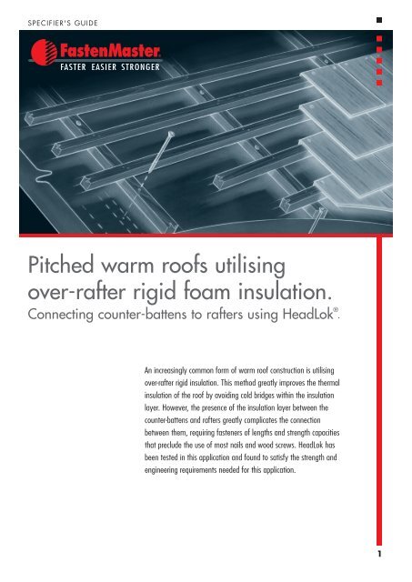
<strong>over</strong>-<strong>rafter</strong> <strong>rigid</strong> <strong>foam</strong> insulation.<br />
Connecting counter-battens to <strong>rafter</strong>s using HeadLok ® .<br />
An increasingly common form of <strong>warm</strong> roof construction is <strong>utilising</strong><br />
<strong>over</strong>-<strong>rafter</strong> <strong>rigid</strong> insulation. This method greatly improves the thermal<br />
insulation of the roof by avoiding cold bridges within the insulation<br />
layer. However, the presence of the insulation layer between the<br />
counter-battens and <strong>rafter</strong>s greatly complicates the connection<br />
between them, requiring fasteners of lengths and strength capacities<br />
that preclude the use of most nails and wood screws. HeadLok has<br />
been tested in this application and found to satisfy the strength and<br />
engineering requirements needed for this application.<br />
1
Specifier's Guide<br />
Warm roof installations<br />
<strong>utilising</strong> HeadLok ®<br />
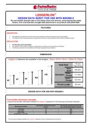
HEADLOK DIMENSIONAL DATA<br />
TABLe 1<br />
Available Lengths<br />
Thread Length<br />
125mm, 150mm, 175mm, 200mm,<br />
225mm<br />
51mm<br />
Head Diameter 15.9mm Outer (Major)<br />
Thread<br />
Diameter<br />
Plain Shank<br />
Diameter<br />
4.8mm<br />
FASTENER SIZE SELECTION<br />
TABLe 2<br />
Thickness of <strong>over</strong>-<strong>rafter</strong><br />
<strong>rigid</strong> insulation (mm)<br />
Length of HeadLok<br />
fastener (mm)<br />
Inner (Minor)<br />
Thread<br />
Diameter<br />
6.7mm<br />
4.4mm<br />
50 70 100 120 150<br />
125 150 175 200 225<br />
NOTES<br />
• Length of HeadLok fastener = Thickness of counter-batten +<br />
Thickness of <strong>rigid</strong> insulation + 51<br />
• Minimum thickness of counter-batten is 25mm<br />
• The threaded length of the HeadLok fastener must be fully inserted<br />
into the <strong>rafter</strong><br />
Thread Engagement<br />
Correct<br />
Incorrect<br />
Fastener Head Depth<br />
Correct Incorrect Incorrect<br />
INSTALLATION PROCEDURE<br />
• Select the appropriate fastener length from the<br />
FASTENER SIZE SELECTION table based on the insulation<br />
thickness. Threads should fully engage the <strong>rafter</strong> (See<br />
THREAD ENGAGEMENT section.)<br />
• Centre the counter-batten <strong>over</strong> the underlying <strong>rafter</strong><br />
by measuring and marking the <strong>rafter</strong> location onto the<br />
insulation surface first.<br />
• Using a drill set to low speed install the HeadLok<br />
screw through the centre of the counter-batten and<br />
perpendicular to the roof slope.<br />
• Install fasteners according to the REQUIRED SPACINGS<br />
table shown on the next page.<br />
• In cases where the limitations following this table are<br />
not met, or a design professional chooses to calculate<br />
the spacing, use the PERMISSIBLE STRENGTH DATA<br />
included in this guide to make these calculations.<br />
• Do not install fasteners closer than 18mm from<br />
counter-batten edge or 75mm from counter-batten end.<br />
• Drive the fastener so that the top of the head is lightly<br />
embedded into the top surface of the counter-batten. To<br />
ensure proper performance, do not underdrive or <strong>over</strong>drive<br />
the fastener. (See FASTENER HEAD DEPTH section.)<br />
• If a split occurs in the batten during installation, or the<br />
head fails to sink flush due to spinning free, install a<br />
supplemental fastener a minimum of 100mm from<br />
original location.<br />
Specifier's Guide | Warm roof installations <strong>utilising</strong> HeadLok ®<br />
2
Specifier's Guide<br />
Warm roof installations<br />
<strong>utilising</strong> HeadLok ®<br />
REQUIRED SPACINGS FOR HEADLOK FASTENERS ALONG RAFTERS<br />
IN PITCHED WARM ROOFS WITH OVER-RAFTER RIGID INSULATION<br />
The required spacing of HeadLok fasteners along the <strong>rafter</strong>s of duo-pitch <strong>roofs</strong> are shown in the Table 3 for three dead<br />
weight ranges of tiled or slated roof claddings:<br />
TABLe 3<br />
SPACING (MM) OF HEADLOK FASTENERS ALONG RAFTER FOR:<br />
Rafters at centres (mm) of:<br />
Roof cladding of dead weight,<br />
vertical on slope, in the range<br />
of 0.2-0.4 kN/m 2<br />
Roof cladding of dead weight,<br />
vertical on slope, in the range<br />
of 0.4-0.6 kN/m 2<br />
Roof cladding of dead weight,<br />
vertical on slope, in the range<br />
of 0.6-0.9 kN/m 2<br />
600 600 500 400<br />
480 600 600 500<br />
400 600 600 600<br />
The basis and limitations for using the spacing<br />
recommendations of Table 3 are:<br />
• Each spacing is dictated either by the need<br />
to provide adequate resistance against the<br />
component of dead and imposed roof loading<br />
acting down and parallel to the roof slope<br />
or by the need to provide resistance against<br />
wind uplift.<br />
• The spacings only apply for duo-pitch <strong>roofs</strong><br />
with pitches (α) between 30° and 50°. The<br />
dead weights of tile or slate roof claddings<br />
are as shown, vertical on slope. The imposed<br />
roof load (kN/m 2 )acting on the roof, vertical<br />
on plan, is taken as 0.75[(60-α)/α].<br />
• For sites with an altitude ≤ 300m, the roof is<br />
located in the region of the United Kingdom<br />
in red on the map shown here. Alternatively<br />
for sites with an altitude ≤ 100m, the roof is<br />
located in the region of the United Kingdom<br />
shown in green on the map. The roof may<br />
be located in a sea, country or town category<br />
of terrain as defined by clause 1.7.2 of<br />
BS6399-2 provided that its topography is<br />
not considered to be significant according to<br />
clause 2.2.2.2 of BS6399-2.<br />
• The height of the ridge of the duo-pitch roof is less than 15m above ground level.<br />
• There is a ceiling fixed to the underside of the <strong>rafter</strong>s which resists the internal wind pressures.<br />
• Gable <strong>over</strong>hangs do not exceed 300mm.<br />
Londonderry<br />
Belfast<br />
Armagh<br />
Map of UK Wind Zones<br />
Oban<br />
Inverness<br />
Aberdeen<br />
Glasgow<br />
Dundee<br />
Edinburgh<br />
Aberystwyth<br />
Swansea<br />
Cardiff Bristol<br />
Plymouth<br />
Carlisle<br />
York<br />
Preston Leeds<br />
Liverpool Manchester<br />
Sheffield<br />
Bournemouth<br />
Newcastle<br />
Kingston<br />
upon-Huff<br />
Stoke Nottingham<br />
Leicester<br />
Birmingham<br />
Brighton<br />
Norwich<br />
Northampton<br />
Ipswich<br />
Bedford<br />
Oxford<br />
London<br />
60˚00'<br />
59˚30'<br />
59˚00'<br />
58˚30'<br />
58˚00'<br />
57˚30'<br />
57˚00'<br />
56˚30'<br />
56˚00'<br />
55˚30'<br />
55˚00'<br />
54˚30'<br />
54˚00'<br />
53˚30'<br />
53˚00'<br />
52˚30'<br />
52˚00'<br />
51˚30'<br />
51˚00'<br />
50˚30'<br />
50˚00'<br />
49˚30'<br />
49˚00'<br />
349˚ 350˚ 351˚ 352˚ 353˚ 354˚ 355˚ 356˚ 357˚ 358˚ 359˚ 0˚ 1˚ 2˚ 3˚<br />
3<br />
Specifier's Guide | Warm roof installations <strong>utilising</strong> Headlok ®
Specifier's Guide<br />
Warm roof installations<br />
<strong>utilising</strong> HeadLok ®<br />
PERMISSIBLE STRENGTH DATA FOR<br />
HEADLOK FASTENERS CONNECTING<br />
COUNTER-BATTENS TO RAFTERS<br />
THROUGH RIGID INSULATION BOARD<br />
Permissible lateral and withdrawal loads are given<br />
below for HeadLok fasteners in the specific application<br />
of connecting counter-battens to <strong>rafter</strong>s through <strong>rigid</strong><br />
insulation board under the following conditions:<br />
1. The 51mm threaded part of the screw must be fully<br />
inserted into the <strong>rafter</strong>, whose strength class should<br />
be C16 or better.<br />
NOTES<br />
1. In view of the presence of the <strong>rigid</strong> insulation, the permissible lateral<br />
load-carrying capacity of the HeadLok connection between the<br />
counter-batten and the <strong>rafter</strong> cannot be evaluated using annex G of<br />
BS5268-2 as it is not a direct timber-timber connection. Instead, the<br />
permissible lateral load-carrying capacity of this connection is derived,<br />
using safety factors appropriate to BS5268-2, from a bespoke testing<br />
programme undertaken in April 2008 at Brighton University and<br />
described in TimberSolve report no. OLY.O1-01 entitled ‘HeadLok<br />
screws manufactured by Fastenmaster. Derivation of permissible loads<br />
for the application of connecting counter-battens to <strong>rafter</strong>s in <strong>roofs</strong>.’<br />
2. The permissible withdrawal load of HeadLok fasteners is determined<br />
from tests undertaken in accordance with EN14592 at CERAM.<br />
2. The screw head should be lightly embedded into the top<br />
surface of the counter-batten, whose nominal thickness<br />
should not be less than 25mm.<br />
FM09208-PDF<br />
3. The spacing of the screws along the <strong>rafter</strong> should not<br />
exceed 600mm.<br />
4. Rigid insulation thicknesses in the range 50-150mm.<br />
Permissible lateral (parallel to roof slope) load =<br />
0.20 kN (all load durations)<br />
Short-term permissible withdrawal load = 0.89 kN<br />
CHECK ON RESISTANCE AGAINST WIND UPLIFT<br />
For duo-pitch <strong>roofs</strong> whose ridge height exceeds 15m or otherwise not meeting the conditions pertaining to the wind<br />
zones of the map shown on page 3, a check on resistance against wind uplift should be made using the equation below.<br />
As stipulated in BS5268-3, this equation incorporates a factor of safety of 1.4 against wind uplift.<br />
Maximum allowable wind uplift u.d. load normal to slope =<br />
HeadLok s-t. perm. withdrawal load + Min. dead u.d. load normal on slope<br />
1.4(Rafter centres)(HeadLok spacing) 1.4<br />
FOR FURTHER TECHNICAL DATA PLEASE CONTACT:<br />
TimberSolve Ltd.<br />
Tel: 01420 549201<br />
Email: Solutions@timbersolve.co.uk<br />
<strong>FastenMaster</strong> ® and HeadLok ® are trademarks of OMG, Inc.<br />
Copyright © 2010 OMG, Inc. All rights reserved.<br />
FOR ordering information PLEASE CONTACT:<br />
OSC<br />
Freephone: 0800 652 2203<br />
Email: enquiries@oscsales.com<br />
4<br />
Specifier's Guide | Warm roof installations <strong>utilising</strong> Headlok ®