UMG 104 – More than just a Multimeter
UMG 104 – More than just a Multimeter
UMG 104 – More than just a Multimeter

Create successful ePaper yourself
Turn your PDF publications into a flip-book with our unique Google optimized e-Paper software.
Smart Energy &<br />
Power Quality Solutions<br />
✔<br />
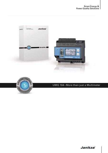
<strong>UMG</strong> <strong>104</strong> <strong>–</strong> <strong>More</strong> <strong>than</strong> <strong>just</strong> a <strong>Multimeter</strong>
<strong>UMG</strong> <strong>104</strong><br />
<strong>UMG</strong> <strong>104</strong> <strong>–</strong> <strong>More</strong> <strong>than</strong> <strong>just</strong> a <strong>Multimeter</strong><br />
The <strong>UMG</strong> <strong>104</strong> equipped with a 500 MHz DSP (digital<br />
signal processor) is a very fast and powerful power<br />
analyser. The continuous scanning of the 8 channels with<br />
20 kHz per channel allows the recording of all electrical<br />
parameters (more <strong>than</strong> 800 values), minimum - and<br />
maximum - values, and the main power quality values<br />
such as harmonics (up to the 40th, each phase with the<br />
detection of direction).<br />
Based on these data loss of production can be avoided,<br />
concepts can be developed, such as the electricity cost<br />
reduction programs, and measures introduced. And<br />
finally the improvements can be monitored and recorded<br />
with the <strong>UMG</strong> <strong>104</strong> as well.<br />
Using modern communication architectures, the acquired<br />
data are fed to a central location, in powerful databases,<br />
stored centrally and made available for further processing<br />
in an open architecture. The easy integration into an<br />
existing building control system or PLC environment<br />
extends the capabilities of the <strong>UMG</strong> <strong>104</strong>.<br />
Applications<br />
• Replacement of analogue and digital instrumentation<br />
• Consumption data collection and analysis (load<br />
profiles)<br />
• Continuous power quality monitoring<br />
• Cost center management, i.e. breakdown of energy<br />
costs, e.g. allocation per product<br />
• Remote control and monitoring of equipment and<br />
processes<br />
• Protection of networks<br />
• “Sensor” for building management systems or PLC<br />
Various versions with UL-approval available!<br />
1
Power analyser <strong>UMG</strong> <strong>104</strong><br />
<strong>UMG</strong> <strong>104</strong> overview<br />
excess value by additional functions<br />
By integration of new functions, the <strong>UMG</strong> <strong>104</strong><br />
exceeds all limits of digital panel meters:<br />
kWh-meter, kvarh-meter<br />
Harmonic analyzer<br />
Multifunctional power meter<br />
Event writer<br />
Supervision of condition<br />
Data logger<br />
The <strong>UMG</strong> <strong>104</strong> can accept up to 4 current and 4 voltage<br />
inputs, which allows monitoring of up to 4 single phase<br />
circuits. Potential applications include data centers,<br />
office buildings, motor control centers, etc.<br />
Cost-effective, fast and safe communication<br />
Modbus and Profibus<br />
In many cases the costs for installation and communication<br />
(e.g. peripheral equipment for field buses) exceed those<br />
for the respective power meters. Integration of the <strong>UMG</strong><br />
<strong>104</strong> in an existing field bus architecture means a fast,<br />
cost-efficient and reliable communication. Additional<br />
interfaces enable the integration of the power analysers<br />
into PLC or building automation systems. The use of open<br />
standards offers great flexibility to the user.<br />
Easy integration of devices with Ethernet<br />
interface<br />
With the Modbus interface function of <strong>UMG</strong> <strong>104</strong> you<br />
can connect via Modbus gateways (for example <strong>UMG</strong><br />
508, <strong>UMG</strong> 604, ...) to Ethernet. Each instrument with a<br />
Modbus RTU interface can be connected, if its data format<br />
and function codes correspond. Data can be scaled and<br />
labelled.<br />
Highspeed Modbus<br />
The devices of <strong>UMG</strong> <strong>104</strong> series can transfer data via<br />
RS485 interface with a speed of up to 921,6 kB/s among<br />
each other device of this series.<br />
RS 485<br />
Profibus<br />
<strong>UMG</strong> 508<br />
<strong>UMG</strong> <strong>104</strong><br />
<strong>UMG</strong> <strong>104</strong><br />
Example PLC communication with Profibus or Modbus<br />
Example Ethernet gateway<br />
2
Power analyser <strong>UMG</strong> <strong>104</strong><br />
Central<br />
Building<br />
Control<br />
System PLC Software<br />
Grids<br />
• IT, TN, TT - Grids<br />
• 3 and 4 wire grids<br />
• up to 4 single phase grids<br />
Interfaces<br />
• RS 232<br />
• RS 485<br />
2 Digital inputs<br />
• Pulse input<br />
• Alarm input logic<br />
• Condition monitoring<br />
• High/ low tariff changeover<br />
2 Digital outputs<br />
• Pulse output kWh/ kvarh<br />
• Switching output<br />
• Limit output<br />
• Logical output<br />
Profibus connection (optional)<br />
Communication Protocols<br />
• Profibus (DP/V0)<br />
• Modbus (RTU)<br />
Temperature input<br />
• PT 100, PT 1000, KTY 83, KTY 84<br />
Accuracy<br />
• Energy: class 0.5S (.../5A)<br />
• Current: 0.2 %<br />
• Voltage: 0.2 %<br />
Memory<br />
• 4 MByte Flash<br />
Power quality<br />
• Harmonics, 1st- 40th<br />
• THD-U/I<br />
• Unbalance<br />
3
Functions and technical data<br />
Overview of product variants<br />
Three/four phase power analysers; 50/ 60Hz; current transformer ../1/5A; including GridVis programming and analysis software.<br />
Supply Voltage<br />
Interfaces<br />
95...240 V AC,<br />
135...340 V DC<br />
±10% of nominal range<br />
50...110V AC<br />
50...155V DC<br />
±10% of nominal range<br />
20...55V AC<br />
20...77V DC<br />
±10% of nominal range<br />
4 Voltage and<br />
4 Current inputs<br />
2 Digital inputs<br />
2 Digital outputs<br />
1 Temperature input<br />
RS 232<br />
RS 485<br />
Profibus DP V0<br />
Type<br />
Artikel-Nr.<br />
• - - • • • • • • - <strong>UMG</strong> <strong>104</strong> 52.20.001<br />
- • - • • • • • • - <strong>UMG</strong> <strong>104</strong> 52.20.003<br />
- - • • • • • • • - <strong>UMG</strong> <strong>104</strong> 52.20.005<br />
• - - • • • • • • • <strong>UMG</strong> <strong>104</strong> P 52.20.002<br />
- - • • • • • • • • <strong>UMG</strong> <strong>104</strong> P 52.20.006<br />
- = not possible • = included<br />
Features<br />
Memory Measurement data 4 MB<br />
Clock<br />
+/- 1 min per month<br />
Operating hours counter<br />
yes<br />
Tarifs<br />
4 x real energy / 4 x reactive energy<br />
Peripherals<br />
Digital inputs as status or pulse input 2<br />
Digital outputs as switching or pulse output 2<br />
Temperature input PT100, PT1000, KTY83, KTY84 1<br />
Password protection<br />
yes<br />
Software GridVis yes<br />
Communication<br />
Interfaces<br />
RS 232 9.6, 19.2, 38.4, 115.2 kbps yes<br />
RS 485 9.6, 19.2, 38.4, 57.6, 76.8, 115.2, 921.6 kbps yes<br />
Profibus DP Sub D9-pole up to 12 Mbps yes, variant P<br />
Protocols<br />
Modbus RTU<br />
yes<br />
Profibus DP V0<br />
yes, variant P<br />
Measuring range<br />
Voltage L-N, AC (without PT)<br />
Voltage L-L, AC (without PT)<br />
Current (Transformer: x/1 und x/5 A)<br />
Frequency of fundamental<br />
Grids<br />
Measurement in grids<br />
10…300 V AC<br />
17…520 V AC<br />
0.005..7.5 A<br />
45 ..65 Hz<br />
IT, TN, TT<br />
1ph, 2ph, 3 ph, 4 ph up to 4 times 1ph<br />
4
Functions and technical data<br />
Technical data<br />
Nominal voltage 3-phase 4-wire grid (L-N, L-L) 277/480 V AC<br />
3-phase 3-wire grid (L-L)<br />
480 V AC<br />
Overvoltage class 300 V CATIII<br />
Quadrants 4<br />
Continuous Measurement yes<br />
Sampling rate, 8 channels per channel 20 kHz<br />
Weight<br />
350 g<br />
Dimensions<br />
W=107.5 mm x D=90 mm x H=82 mm<br />
Mounting according to IEC EN60999-1/ DIN EN 50022 35 mm DIN rail<br />
Working temperature -10…55 °C<br />
Connectable wires (U/I) one wire, more wires, fine stranded wires 0.08 - 2.5 mm²<br />
cable end sleeve<br />
1.5 mm²<br />
Protection class according to EN60529 IP 20<br />
Measured values<br />
Voltage L1, L2, L3, L4, L1-L2, L2-L3, L1-L3 accuracy ±0.2%<br />
Current L1, L2, L3, L4, Sum L1-L3, Sum L1-L4 accuracy ±0.2%<br />
K-factor L1, L2, L3, L4 yes<br />
Rotating current components Positive/ Negative/ Zero Phase Sequence yes<br />
Real, apparent, reactive power L1, L2, L3, L4, Sum L1-L3, Sum L1-L4 accuracy ±0.4% (EN61557-12)<br />
Cos-phi / power factor L1, L2, L3, L4, Sum L1-L3, Sum L1-L4 yes<br />
Phase angle L1, L2, L3, L4 yes<br />
Real energy (kWh)<br />
Reactive energy (Karh)<br />
L1, L2, L3, L4, Sum L1-L3, Sum L1-L4:<br />
- Consumed real energy (rate 1, rate 2)<br />
- Supplied real energy (rate 1, rate 2)<br />
L1, L2, L3, L4, Sum L1-L3, Sum L1-L4:<br />
- Inductive energy (rate 1, rate 2)<br />
- Capacitive reactive energy<br />
Class 0.5S (…/5 A),<br />
Class 1 (…/1 A)<br />
Class 2<br />
Reactive energy (kVAh) L1, L2, L3, L4, Sum L1-L3, Sum L1-L4 yes<br />
Wave form voltage L1, L2, L3, L4 yes<br />
Frequency of mains<br />
accuracy ±0.01 Hz<br />
Temperature input accuracy ±1.5%<br />
Average values<br />
yes<br />
Minimum and maximum values<br />
yes<br />
Power quality<br />
Harmonics, 1st- 40th<br />
Current, voltage, real/reactive power (±)<br />
L1, L2, L3, L4<br />
Distortion factor THD-U in % L1, L2, L3, L4 yes<br />
Distortion factor THD-I in % L1, L2, L3, L4 yes<br />
Unbalance<br />
Positive/ Negative/ Zero Phase Sequence<br />
Inrush-currents 10 ms no<br />
Malfunction writer<br />
Short-term interruptions<br />
accuracy V, I Class 1 (EN61000-4-7)<br />
yes<br />
yes<br />
no<br />
no<br />
5
<strong>UMG</strong> <strong>104</strong><br />
Connection diagram <strong>UMG</strong> <strong>104</strong><br />
Dimensional drawing<br />
90 mm<br />
90 mm<br />
107,5 mm 50 mm<br />
76 mm<br />
82 mm<br />
front view side view<br />
6