Walsin Technology Corporation
Walsin Technology Corporation
Walsin Technology Corporation

Create successful ePaper yourself
Turn your PDF publications into a flip-book with our unique Google optimized e-Paper software.
Chip Resistors<br />
www.passivecomponent.com<br />
Chip Resistors Array : Convex Termination<br />
Feature<br />
Application<br />
1. High reliability and stability 1. Consumer electrical equipment, PDA Digital Camcorder,<br />
2. Reduced size of final equipment 2. EDP, Computer application<br />
3. Lower assembly cost and higher surface mounted efficiency 3. Mobile phone, Telecom<br />
4. Higher component and equipment reliability 4. DIMM<br />
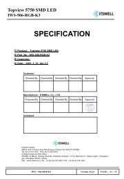
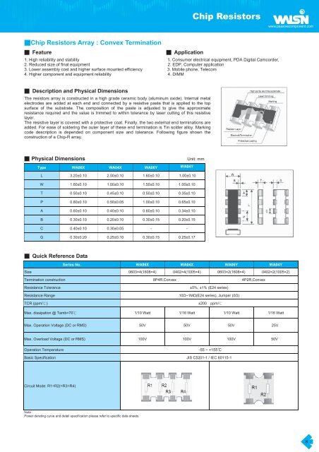
Description and Physical Dimensions<br />
The resistors array is constructed in a high grade ceramic body (aluminum oxide). Internal metal<br />
electrodes are added at each end and connected by a resistive paste that is applied to the top<br />
surface of the substrate. The composition of the paste is adjusted to give the approximate<br />
resistance required and the value is trimmed to within tolerance by laser cutting of this resistive<br />
layer.<br />
The resistive layer is covered with a protective coat. Finally, the two external end terminations are<br />
added. For ease of soldering the outer layer of these end termination is Tin solder alloy. Marking<br />
code description is depended on component size and tolerance. Following figure shown the<br />
construction of a Chip-R array.<br />
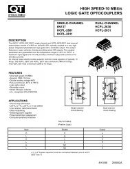
Physical Dimensions<br />
Unit: mm<br />
Type WA06X WA04X WA06Y WA04Y<br />
L 3.20±0.10 2.00±0.10 1.60±0.10 1.00±0.10<br />
W 1.60±0.10 1.00±0.10 1.50±0.10 1.00±0.10<br />
T 0.50±0.10 0.45±0.10 0.50±0.10 0.35±0.10<br />
P 0.80±0.10 0.50±0.05 1.00±0.10 0.65±0.10<br />
A 0.60±0.10 0.40±0.10 0.60±0.10 0.34±0.10<br />
B 0.30±0.10 0.20±0.10 0.30±0.15 0.20±0.15<br />
C 0.40±0.10 0.30±0.05 - -<br />
G 0.30±0.20 0.25±0.10 0.30±0.15 0.25±0.17<br />
Quick Reference Data<br />
Series No. WA06X WA04X WA06Y WA04Y<br />
Size 0603×4(1608×4) 0402×4(1005×4) 0603×2(1608×4) 0402×2(1005×2)<br />
Termination construction 8P4R,Convex 4P2R,Convex<br />
Resistance Tolerance<br />
Resistance Range<br />
±5%, ±1% (E24 series)<br />
10~1M(E24 series), Jumper (0)<br />
TCR (ppm/) ±200 ppm/<br />
Max. dissipation @ Tamb=70 1/10 Watt 1/16 Watt 1/10 Watt 1/16 Watt<br />
Max. Operation Voltage (DC or RMS) 50V 50V<br />
50V<br />
25V<br />
Max. Overload Voltage (DC or RMS) 100V 100V<br />
100V<br />
50V<br />
Operation Temperature<br />
-55 ~ +155 C<br />
Basic Specification JIS C5201-1 / IEC 60115-1<br />
Circuit Mode: R1=R2(=R3=R4)<br />
Note :<br />
Power derating curve and detail specification please refer to specific data sheets.<br />
8