Walsin Technology Corporation
Walsin Technology Corporation
Walsin Technology Corporation

You also want an ePaper? Increase the reach of your titles
YUMPU automatically turns print PDFs into web optimized ePapers that Google loves.
Chip Resistors<br />
www.passivecomponent.com<br />
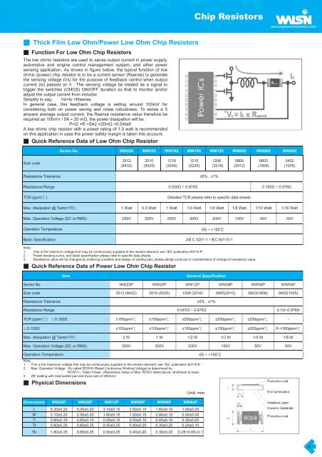
Thick Film Low Ohm/Power Low Ohm Chip Resistors<br />
Function For Low Ohm Chip Resistors<br />
The low ohmic resistors are used to sense output current in power supply,<br />
automotive and engine control management system, and other power<br />
sensing application. As shows in figure below, the typical function of low<br />
ohmic (power) chip resistor is to be a current sensor (Rsense) to generate<br />
the sensing voltage (Vs) for the purpose of feedback control when output<br />
current (lo) passed on it . The sensing voltage be treated as a signal to<br />
trigger the switches (CMOS) ON/OFF duration so that to monitor and/or<br />
adjust the output current from inductor.<br />
Simplify to say,<br />
Vs=Io ×Rsense.<br />
In general case, this feedback voltage is setting around 100mV for<br />
considering both on power saving and noise robustness. To sense a 5<br />
ampere average output current, the Rsense resistance value therefore be<br />
required as 100mV / 5A = 20 m, the power dissipation will be :<br />
P=I2 ×R =5A2 ×20m =0.5Watt<br />
A low ohmic chip resistor with a power rating of 1.0 watt is recommended<br />
on this application in case the power safety margin is taken into account.<br />
Quick Reference Data of Low Ohm Chip Resistor<br />
Series No. WW25X WW20X WW18X WW10X WW12X WW08X WW06X WW04X<br />
Size code<br />
2512<br />
(6432)<br />
2010<br />
(5025)<br />
1218<br />
(3248)<br />
1210<br />
(3225)<br />
1206<br />
(3216)<br />
0805<br />
(2012)<br />
0603<br />
(1608)<br />
0402<br />
(1005)<br />
Resistance Tolerance ±5% , ±1%<br />
Resistance Range 0.020 ~ 0.976 0.100 ~ 0.976<br />
TCR (ppm/)<br />
Detailed TCR please refer to specific data sheets<br />
Max. dissipation @ Tamb=70 1 Watt 0.5 Watt 1 Watt 1/3 Watt 1/4 Watt 1/8 Watt 1/10 Watt 1/16 Watt<br />
Max. Operation Voltage (DC or RMS) 250V 200V 200V 200V 200V 100V 50V 50V<br />
Operation Temperature<br />
-55 ~ +155 C<br />
Basic Specification JIS C 5201-1 / IEC 60115-1<br />
Note :<br />
1. This is the maximum voltage that may be continuously supplied to the resistor element, see “IEC publication 60115-9” .<br />
2. Power derating curve, and detail specification please refer to specific data sheets.<br />
3. Resistance value will be changed by soldering condition and design of solding pad, please design products in consideration of change of resistance value.<br />
Quick Reference Data of Power Low Ohm Chip Resistor<br />
Item<br />
General Specification<br />
Series No. WW25P WW20P WW12P WW08P WW06P WW04P<br />
Size code 2512 (6432) 2010 (5025) 1206 (3216) 0805(2012) 0603(1608) 0402(1005)<br />
Resistance Tolerance ±5% , ±1%<br />
Resistance Range 0.047 ~ 0.976 0.1~0.976<br />
TCR (ppm/) 0.100 ±150ppm/ ±150ppm/ ±200ppm/ ±200ppm/ ±250ppm/ -<br />
0.100 ±100ppm/ ±100ppm/ ±100ppm/ ±150ppm/ ±200ppm/ 0~+300ppm/<br />
Max. dissipation @ Tamb=70 2 W 1 W 1/2 W 1/3 W 1/4 W 1/8 W<br />
Max. Operation Voltage (DC or RMS) 300V 200V 200V 150V 50V 50V<br />
Operation Temperature<br />
Note :<br />
1. This is the maximum voltage that may be continuously supplied to the resistor element, see “IEC publication 60115-8” .<br />
2. Max. Operation Voltage : So called RCWW (Rated Continuous Working Voltage) is determined by<br />
RCWV=Rater Power ×Resistance Value or Max. RCWV listed above, whichever is lower.<br />
3. 2W loading with total solder-pad and trace size of 300mm2<br />
Physical Dimensions<br />
Unit:mm<br />
Dimensions WW25P WW20P WW12P WW08P WW06P WW04P<br />
L 6.30±0.20 5.00±0.20 3.10±0.15 2.00±0.15 1.60±0.10 1.00±0.05<br />
W 3.10±0.20 2.50±0.20 1.60±0.15 1.20±0.15 0.80±0.10 0.50±0.05<br />
T 0.60±0.15 0.60±0.10 0.55±0.10 0.50±0.10 0.45±0.10 0.35±0.05<br />
Tt 0.60±0.25 0.60±0.25 0.50±0.25 0.40±0.20 0.30±0.20 0.20±0.10<br />
Tb 1.80±0.25 0.65±0.25 0.50±0.25 0.40±0.20 0.30±0.20 0.25+0.05/-0.1<br />
-55 ~ +155 C<br />
6