download pls product overview
download pls product overview
download pls product overview

Create successful ePaper yourself
Turn your PDF publications into a flip-book with our unique Google optimized e-Paper software.
Proximity Laser Scanner<br />
PLS<br />
T E C H N I C A L D E S C R I P T I O N
Certification<br />
Technical Description<br />
2 8 008 316<br />
© SICK AG . Safety Systems . Germany . All rights reserved
Table of Contents<br />
1 Approvals and Certificates ................................................................. 4<br />
2 Notices / Regulation Use .................................................................... 6<br />
3 How the PLS Works ............................................................................... 7<br />
Principle of function .................................................................... 7<br />
Fields and measuring range of the PLS ............................. 8<br />
4 Fields of Application – What the PLS Can Do ............................ 9<br />
Area protection ........................................................................... 9<br />
Internal space protection ....................................................... 9<br />
Vehicle protection and navigation ...................................... 10<br />
Measurement of contours ................................................... 10<br />
5 Location Planning .................................................................................. 11<br />
Range of the PLS ....................................................................... 11<br />
5.1 Stationary protection with PLS ........................................... 12<br />
Important notes on configuration ...................................... 12<br />
Location planning ...................................................................... 13<br />
Restart definition ....................................................................... 16<br />
Mounting recommendations for PLS ............................... 16<br />
5.2 Mobile protection with PLS .................................................. 19<br />
Location planning ...................................................................... 20<br />
Calculation of the necessary protective field ................ 21<br />
Configuration examples .......................................................... 22<br />
5.3 If you use several PLS units ................................................. 23<br />
6 Supply Package ..................................................................................... 24<br />
Recommended accessories .............................................. 24<br />
Connection set .......................................................................... 24<br />
Interface cable ........................................................................... 24<br />
7 Mounting the PLS .................................................................................. 25<br />
8 Connecting Up the PLS ...................................................................... 28<br />
Connecting the power connector...................................... 29<br />
Connection examples ............................................................. 29<br />
Notes ............................................................................................. 33<br />
Connecting the interface connector ................................. 34<br />
Short-term connection to a PC .......................................... 35<br />
Permanent connection to an evaluation computer ... 35<br />
9 Programming the PLS with the User Software ........................ 36<br />
9.1 Installing the user software ................................................. 36<br />
System requirements ............................................................. 36<br />
9.2 What to do ................................................................................... 37<br />
Essential steps .......................................................................... 37<br />
Other options ............................................................................. 37<br />
9.3 Entry: The initial configuration .............................................. 38<br />
Configure hardware .................................................................. 39<br />
Send configuration to PLS ..................................................... 42<br />
Edit monitoring range .............................................................. 43<br />
Send monitoring range to PLS ............................................ 46<br />
9.4 Edit/dimension fields ............................................................. 47<br />
Convert fields .............................................................................. 47<br />
Change scale of segmented field ...................................... 47<br />
Copy and paste fields ............................................................. 48<br />
Save individual fields ................................................................ 48<br />
Fix coordinates .......................................................................... 48<br />
9.5 Teach-in protective field ....................................................... 49<br />
9.6 Monitor protective field ......................................................... 51<br />
9.7 Check settings ........................................................................... 52<br />
9.8 Receive and store configuration ....................................... 53<br />
9.9 Change password .................................................................... 54<br />
9.10 Change screen view ................................................................ 55<br />
9.11 Interrogate fault memory<br />
(system diagnosis) .................................................................. 57<br />
Initial fault diagnosis.................................................................. 57<br />
Interrogate PLS fault memory ............................................. 57<br />
10 Care and Maintenance .......................................................................59<br />
10.1 SICK Service / Hotline ........................................................... 59<br />
10.2 LEDs on the PLS .......................................................................60<br />
10.3 PLS fault table ............................................................................ 61<br />
10.4 Service questionnaire ............................................................62<br />
11 Appendix ..................................................................................................64<br />
11.1 Characteristics ...........................................................................64<br />
11.2 Accessories................................................................................65<br />
PLS variants .................................................................................65<br />
Mounting kits ..............................................................................65<br />
Connection set ..........................................................................65<br />
Interface cables ........................................................................ 65<br />
Documentation and user software ...................................65<br />
Other SICK accessories ........................................................ 65<br />
And also … .................................................................................. 65<br />
11.3 Technical data ............................................................................ 66<br />
11.4 Standards and regulations ................................................... 67<br />
12 Glossar ...................................................................................................... 71<br />
This technical description contains all the information necessary<br />
for project planning and setting up the PLS. You will find in it the<br />
information you need for mechanical mounting, electrical installation<br />
and programming of the PLS.<br />
The description covers the following PLS types:<br />
– PLS 101-312<br />
– PLS 101-112 and PLS 101-212<br />
– PLS 201-113, PLS 201-213 and PLS 201-313<br />
Along with the technical description you are also provided with<br />
an instruction manual, containing important information for dayto-day<br />
use of the PLS.<br />
Keep the technical description and the instruction manual readily<br />
to hand at all times.<br />
Essential sections you should read:<br />
Important notes ................................................ Section 2<br />
Location planning .............................................. Section 5<br />
Supply package,<br />
Mounting and connecting up the PLS: .... Sections 6 to 9<br />
Entry into the user software........................ Sections 9.1 to 9.3<br />
SICK Technical Description PLS – 07/98 3
1 Approvals and Certificates<br />
4<br />
SICK Technical Description PLS – 07/98
SICK Technical Description PLS – 07/98 5
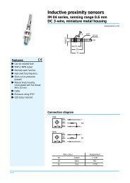
2 Notices / Regulation Use<br />
The PLS proximity laser scanner is a device designed to protect<br />
people and property. It is intended to monitor hazardous areas<br />
in enclosed spaces. PLS is not designed for outdoor use.<br />
Observe the instructions relating to regulation use. SICK cannot<br />
be held liable for damage arising from use of the PLS other than<br />
stipulated.<br />
• Install the PLS in a dry location and protect the unit against<br />
dirt and damage.<br />
• Lay all wires and connecting cables such that they are protected<br />
against damage.<br />
• Make sure that no obstacles in the monitoring range can<br />
obstruct the field of vision of the PLS or cause shadows.<br />
Such shadow areas cannot be monitored by the PLS.<br />
Where there are unavoidable areas of shadow, check<br />
whether they present any risk. Take additional precautionary<br />
measures as necessary.<br />
• Keep the monitoring range free of smoke, fog, steam and<br />
other air pollution. The functioning of the PLS may otherwise<br />
be impaired and error shutdowns may occur.<br />
• Avoid placing strongly reflective objects such as retroreflectors<br />
in the scanning plane of the PLS, as they may influence<br />
its measurement results.<br />
• Mount the PLS so that it cannot be dazzled by sunlight. Also<br />
avoid stroboscopic and fluorescent lamps, as they may influence<br />
the PLS under certain circumstances.<br />
• In mounting, installation and use of the PLS, observe the<br />
standards and regulations applicable in your country. The<br />
Appendix presents a summary of the most important regulations.<br />
• For programming of the monitoring range, take note of the<br />
description of the user software as from section 9. This describes<br />
how to connect the PLS to a PC and how to work<br />
with the user software.<br />
• Before releasing the machine for use, test whether access<br />
to the hazardous area is fully covered by the safety devices.<br />
After release, also check at regular intervals (such as every<br />
morning before beginning work) that the PLS is activated<br />
properly when an intrusion into the protective field occurs.<br />
This test should be carried out along all protective field limits,<br />
in accordance with application-specific regulations.<br />
• If you want to deploy one or more PLS together with a LSI<br />
(Laser Scanner Interface) in your application, to work with<br />
several different switchable or variable protective fields for<br />
example, please also take note of the technical description<br />
of the LSI.<br />
• The PLS must be disposed of in a proper and environmentally<br />
friendly manner at the end of its useful service life.<br />
6<br />
SICK Technical Description PLS – 07/98
3 How the PLS Works<br />
Principle of function<br />
The PLS is an optical sensor which scans its surroundings with<br />
infrared laser beams. It is used to monitor a hazardous area on<br />
a machine or vehicle. The PLS can be used on manually controlled<br />
vehicles, such as narrow-aisle forklifts and other lift trucks,<br />
as well as in driverless transport systems (DTS) such as shunting<br />
cars and free-navigating vehicles.<br />
As a result of its scanning principle, the PLS requires neither<br />
separate receivers nor reflectors.<br />
∆ t<br />
S<br />
E<br />
0 t<br />
E<br />
This has the following advantages:<br />
– You can adapt the monitoring range precisely to the hazardous<br />
area of a machine.<br />
– Since you do not need any receivers or additional reflectors,<br />
you keep the entire area freely accessible and driveable.<br />
– If the hazardous area changes you can alter the sensor simply<br />
by reprogramming the software, with no additional<br />
mounting.<br />
– Different reflective materials do not influence the functioning<br />
of the sensor. This makes the PLS highly versatile in its uses.<br />
S<br />
S<br />
0 t<br />
s ∆ t<br />
The sensor operates on the principle of reflex light time measurement.<br />
It emits very short light pulses. At the same time an<br />
“electronic stopwatch” runs. If the light encounters an object, it<br />
is reflected and thrown back to the sensor. From the time between<br />
sending and receiving, the sensor calculates its distance<br />
from the object.<br />
In the sensor there is also a uniformly rotating mirror which deflects<br />
the light pulses such that they sweep a semicircular area.<br />
By determining the mirror angle, the PLS detects in which direction<br />
the object is located.<br />
From the measured distance and the direction of the object<br />
the sensor determines its precise position.<br />
SICK Technical Description PLS – 07/98 7
Fields and measuring range of the PLS<br />
The monitoring range of the sensor consists of a protective<br />
field and a warning field. You can use the supplied software to<br />
define the two fields and store them in the memory.<br />
The protective field protects the hazardous area of a machine<br />
or vehicle. As soon as the sensor detects an object in the protective<br />
field, it shuts down the machine or stops the vehicle immediately.<br />
This is a safety function. Its safety integrity corresponds to cat.<br />
3 to EN 954-1:<br />
The test basis is:<br />
– For PLS 101-312: Type 3 to IEC/EN 61496-1<br />
– For PLS 101-112 and PLS 101-212: Type 3 to EN 50100-1<br />
Visible area<br />
(e. g. hall walls)<br />
Measurement<br />
length<br />
Warning field<br />
Protective field<br />
You can define the warning field such that the sensor detects<br />
an object before it enters the actual hazardous area, and triggers<br />
an alarm signal for example.<br />
Independent of its evaluation of the protective and warning<br />
fields, the sensor continuously scans its surroundings within its<br />
measuring range. You can evaluate this data for additional<br />
measuring tasks, such as to navigate a DTS or measure contours.<br />
4 m max.<br />
protective<br />
range<br />
approx. 15 m<br />
max. warning range<br />
8<br />
SICK Technical Description PLS – 07/98
4 Fields of Application – What the PLS Can Do<br />
These pages provide an <strong>overview</strong> of the key fields of application<br />
of the PLS.<br />
Area protection<br />
On hazardous stationary machinery the PLS ensures that the<br />
machine (or only its hazardous movement) is shut down as<br />
soon as someone enters the hazardous area. This is done by<br />
means of a protective field ➊ which you can define according to<br />
your needs and store in the PLS.<br />
You can also define a warning field ➋ in front of the actual hazardous<br />
area which triggers an alarm signal as soon as someone<br />
approaches the hazardous area. The person can then move<br />
out of the warning area without the machine or its hazardous<br />
movement having to be stopped. This helps you to safeguard<br />
continuous <strong>product</strong>ion.<br />
Host<br />
Power<br />
Supply<br />
➁<br />
➀<br />
Internal space protection<br />
Where internal spaces exist in large machines, the PLS ensures<br />
the machine can only start up when the internal space is clear.<br />
This is important especially with regard to internal spaces which<br />
are not clearly visible, or not visible at all, from the outside.<br />
In this application the PLS performs only a secondary protective<br />
function. The actual personal protection is provided by a light<br />
grid, whilst the PLS monitors restarting of the machine.<br />
SICK Technical Description PLS – 07/98 9
Vehicle protection and navigation<br />
You can employ the PLS on vehicles, such as driverless transport<br />
systems (DTS), forklifts and shunting cars, to safeguard a<br />
vehicle’s path – on its way through a factory hall for example.<br />
The protective field ➊ of the PLS then ensures that the vehicle<br />
stops if a person or obstacle is standing in the way. You can<br />
also define a warning field ➋ which, for example, triggers an<br />
alarm signal some distance before the person or obstacle is<br />
reached and cuts the speed of the vehicle. You can protect<br />
both manually controlled vehicles and driverless transport systems<br />
(DTS).<br />
Independent of the protective and warning field settings, the<br />
PLS continuously monitors the positions of objects in its<br />
surroundings ➌. Vehicles with an internal navigation system can<br />
use this ambient data to update their system (PLS 101-31x<br />
only). For this, the PLS is permanently linked to the on-board<br />
computer of the DTS. The data transmitted by the PLS is encoded<br />
in telegrams. The telegram descriptions can be ordered<br />
from SICK.<br />
➂<br />
➁<br />
➀<br />
Measurement of contours<br />
You can use the measurement principle of the PLS for a wide<br />
variety of measuring tasks, such as:<br />
– Size measurement of goods<br />
– Position detection of goods (e.g. pallets)<br />
– Cross-section measurement in aisles and tunnels<br />
– Profile measurement of goods or vehicles<br />
– Protrusion monitoring of goods in shelves<br />
– Filling level measurement<br />
– Length measurement<br />
If you want solutions for measurement problems of this kind,<br />
please order documentation on our series LMS laser scanner,<br />
which is suitable for such tasks.<br />
B<br />
X<br />
Y<br />
H<br />
10<br />
SICK Technical Description PLS – 07/98
5 Location Planning<br />
The PLS monitors hazardous areas and protects operating personnel<br />
and plant. To enable it to fulfill those tasks, you need to<br />
observe a number of rules and safety criteria when choosing its<br />
location. The key information with regard to this is presented on<br />
the following pages.<br />
Note:<br />
It may be that other standards and regulations not cited<br />
here are also of importance to your application.<br />
If you are unsure about your application, please contact your<br />
local SICK office.<br />
Always choose a location<br />
– which provides the maximum safety in the hazardous area<br />
– in which no obstacles can obstruct the field of vision of the<br />
PLS or cause umbra shadows<br />
– in which the PLS is protected against damp, dirt and damage<br />
– in which the PLS is not influenced by sunlight or artificial light<br />
sources<br />
– which is as accessible as possible for electrical installation<br />
work.<br />
The PLS can in principle be operated in any mounting orientation,<br />
for measuring tasks for example. But you should note:<br />
When using the PLS in normal area protection and safety applications,<br />
only a horizontal orientation of the protective field, with<br />
a slight tilt where necessary, is permitted!<br />
Range of the PLS<br />
The PLS measures its surroundings in a semicircular plane<br />
(scanning angle 180°). Employment of an optoelectronic safety<br />
device as area protection requires a minimum resolution of<br />
70 mm at a specific mounting height. The PLS guarantees this<br />
resolution to a distance of 4 metres. Therefore the system<br />
software of types PLS 101-312, PLS 101-112 and PLS 101-212<br />
limits the maximum radius of the protective field automatically<br />
to 4 metres.<br />
The other PLS types do not have this limitation, and so are not<br />
certified for personnel protection.<br />
The protective field protecting the hazardous area of a machine<br />
or vehicle may have a maximum radius of 4 metres. The<br />
PLS shuts the machine down or stops the vehicle in the event<br />
of an intrusion into the protective field.<br />
The warning field may have any radius up to 50 metres. You<br />
should note, however, that the sensor is able to detect objects<br />
with a reflectance of approx. 20 - 30 % only to a distance of 15<br />
metres.<br />
The measuring range of the PLS extends to a radius of 50 metres.<br />
Up to that distance the PLS is able to detect the contour<br />
data of its surroundings (e.g. the space contour). It can then<br />
additionally evaluate this data for the protective field and the<br />
warning field, provided the reflectance of the object is sufficient<br />
to be detected.<br />
Visible area<br />
(e. g. hall walls)<br />
Measurement<br />
length<br />
Warning field<br />
Protective field<br />
Screen display<br />
4 m max.<br />
protective<br />
range<br />
approx. 15 m<br />
max. warning range<br />
SICK Technical Description PLS – 07/98 11
5.1 Stationary protection with PLS<br />
Important notes on configuration<br />
The sensor should preferably be operated in “with restart inhibit”<br />
mode for area protection. The regulations applicable to the<br />
machine must be observed.<br />
In “with restart inhibit” mode the actuating element for the restart<br />
inhibit must be positioned such that there is full visibility of<br />
the hazardous area. The actuating element for the restart inhibit<br />
must not be accessible from the point directly in front of the<br />
sensor.<br />
In “without restart inhibit” mode the close-up zone 1) . of the sensor<br />
(4 cm wide area measured from the front screen outer<br />
contour) is either to be rendered inaccessible (e.g. by a bar or<br />
undercut) or a proximity scanner with a 4 cm detection range is<br />
to be mounted over the sensor.<br />
For area protection, side access to the machine base is also to<br />
be taken into account when configuring the protective field. This<br />
assumes that a person approaches the machine base from the<br />
side. If side access is possible (no solid restrictions such as a<br />
wall), the protective field should be configured wider than the<br />
machine base.<br />
In area protection applications it must be ensured that, with<br />
protective field widths over 2 metres, there are no retroreflectors<br />
in the immediate proximity of the protective field limits on<br />
the scanning plane. Otherwise corruption of the measured values<br />
is to be expected under extreme conditions. If it is impossible<br />
to avoid having retroreflectors in the scanning plane, an<br />
extra 20 cm should be added to the maximum measuring error<br />
2) .<br />
The maximum measuring error is<br />
• 94 mm for protective fields < 2 m<br />
• 131 mm for protective fields > 2 m<br />
Where there are fixed restrictions (walls) there must be no retroreflectors<br />
in the scanning plane, as otherwise someone could<br />
move along the wall to bypass the protective field.<br />
For both graphic and numeric programming, it must be ensured<br />
for reasons of functionality (solid barriers should not lead to<br />
unintentional shutdown) that where fixed contours exist a distance<br />
of 94 mm for protective fields below 2 metres and 131<br />
mm for protective fields over 2 metres is observed.<br />
Where the teach-in function is used, a 45 mm supplement on<br />
top of the maximum measuring error is required for the accuracy<br />
of the learned contour.<br />
1)<br />
An optical radar cannot distinguish between a dirty<br />
front screen and an obstacle directly in front of the<br />
sensor. For the sake of sake of functionality, the PLS<br />
was designed to reliably detect solid black bodies<br />
such as black cord or shoe leather only at a distance<br />
of 4 cm measured from the outer contour of the front<br />
screen.<br />
2)<br />
Accuracy of the sensor in safety applications: The<br />
sensor determines the distance of an obstacle from<br />
the flight time of a very short light pulse. To attain<br />
optimum accuracy against obstacles of solid black<br />
material (1.8 % reflectance) up to precision triple<br />
reflectors (10,000 % reflectance), the PLS<br />
compensates the received signal. If there is a dark<br />
object in front of a retroreflector, under certain<br />
circumstances (see above) the error distance of 20<br />
cm may be too large. This would mean a person could<br />
intrude 20 cm into the monitored area without being<br />
detected by the PLS. This measuring error occurs only<br />
when the following conditions simultaneously apply:<br />
– The distance to the target is greater than<br />
2 metres.<br />
– The target is smaller than 140 mm.<br />
– The retroreflector is on the scanning plane.<br />
– The reflector is aligned perpendicular to the<br />
sensor within an angle of ± 30°.<br />
– The target reflectance is in the area of 1.8 %.<br />
– The retroreflector is not more than 2 metres<br />
behind the target.<br />
– The reflector is clean and high-quality.<br />
12<br />
SICK Technical Description PLS – 07/98
Location planning<br />
There are two basic alternative procedures for defining mounting<br />
locations:<br />
First option: Using the so-called teach-in mode. In this mode<br />
the PLS measures the ambient contour and stores it (after automatic<br />
correction) as the outer protective field limit. The following<br />
formulae must be applied to check compliance with the<br />
relevant specifications, such as the safety distance and mounting<br />
height, retrospectively.<br />
Second option: Using graphical or numerical protective field input.<br />
In this the specifications to be complied with are ascertained<br />
at the outset and are then set in programming of the<br />
scanner.<br />
The basis for planning the mounting location of the PLS is pr EN<br />
999. It describes the necessary minimum safety distance from<br />
the hazardous area by:<br />
S = (K x T) + C<br />
Where:<br />
S is the minimum distance in millimetres, measured from the<br />
hazardous area to the detection point, detection line, detection<br />
plane or protective field;<br />
K is a parameter in millimeters per second, derived from data<br />
relating to approach speeds of the body or body parts;<br />
T is the stopping time of the overall system in seconds;<br />
C is an additional distance in millimetres which takes account<br />
of the possibility of intrusion into the hazardous area before<br />
tripping of the safety device.<br />
In access protection applications, an approach speed of 1600<br />
mm/s is applied as K.<br />
T results from addition of the response time of the sensor and<br />
the stopping time of the hazardous movement.<br />
C describes the possibility of reaching over the protective field<br />
without tripping the sensor, and varies with the height of the<br />
protective field limit according to the following correlation:<br />
C = 1200 mm - 0.4 H D<br />
(H D<br />
= height of detection)<br />
where C > 850 mm<br />
Consequently:<br />
Where H D<br />
= 0 : C HD=0<br />
= 1200 mm<br />
Where H D<br />
= 875 : C HD=875<br />
= 850 mm<br />
This correlation is shown graphically in the adjacent diagrams<br />
(cases 1 and 2).<br />
Note:<br />
The protective field supplement C is to be chosen dependent<br />
on the height of detection H D<br />
.<br />
In case 2b, protection of marginal areas, note that the<br />
scanning plane is not raised.<br />
Also note that if the sensor is not mounted parallel to the<br />
floor the effective protective field length is reduced.<br />
Hazardous<br />
area<br />
PLS<br />
C = 1200<br />
H D = 0<br />
Case 1: Scanning plane parallel to ground (H D<br />
= 0)<br />
Hazardous<br />
area<br />
Hazardous<br />
area<br />
C = 850<br />
H D = 875<br />
Case 2a: Scanning plane at maximum height and parallel to<br />
ground. (H D<br />
= 875)<br />
H D = 875<br />
C<br />
C = 900 with multiple evaluation = 2<br />
C = 950 with multiple evaluation = 4<br />
etc.<br />
Case 2b: Scanning plane at maximum height, not parallel to ground<br />
(H D<br />
= 875)<br />
SICK Technical Description PLS – 07/98 13
As a secondary condition pr EN 999 stipulates the following<br />
minimum height:<br />
H D<br />
= 15 x (d - 50) mm<br />
Application of this formula is necessary as the leg diameter<br />
changes with the distance from the floor. In this, d is the resolution<br />
of the PLS (d is dependent on the distance from the scanner).<br />
The resolution of the scanner must always be determined at<br />
the point of greatest measuring distance, i.e. at the greatest<br />
occurring protective field length SL max<br />
.<br />
Based on the working principle of the PLS by means of radial<br />
scanning of the surroundings, a resolution is produced which<br />
decreases as the distance from the sensor increases.<br />
Thus a protective field length SL greater than 2.70 meters (only<br />
up to this distance is a scanner resolution of 50 mm guaranteed)<br />
makes a certain detection height necessary. In this way it<br />
is possible to compensate for the lower resolution with greater<br />
leg diameter.<br />
These correlations between SL, H D<br />
, H S<br />
and C are shown graphically<br />
in the adjacent diagrams. In this, H S<br />
is the height of the<br />
scanner plane, measured directly on the sensor.<br />
With horizontal mounting there is no risk of unwanted accessing<br />
at mounting heights below 100 mm (for example crawling under<br />
the scanning plane). To prevent children from crawling underneath,<br />
the maximum mounting height is 200 mm max. Mounting<br />
heights of less than 100 mm are generally not to be recommended,<br />
as in such cases it is possible that the scanner may<br />
accidentally shut down as a result of the increased dust concentration<br />
directly on the floor. For these reasons this mounting<br />
range is often preferred, and consequently is identified as such<br />
in the diagram.<br />
Protective<br />
field<br />
Machine<br />
Longest protective<br />
field length<br />
Resolution of the scanner at the point of longest protective<br />
field length SL<br />
Using the diagram:<br />
Define the maximum protective field length SL max<br />
in your layout.<br />
Shift the right Y-axis (H D<br />
) in parallel onto the located value<br />
SL max<br />
. Then place the desired scanning plane in the remaining<br />
area shaded light gray. The plotted scanning line must not<br />
leave the gray area at any point.<br />
Within the area shaded gray in the diagram any mounting orientation<br />
is possible, provided it does not impair the safety distance.<br />
HS (mm)<br />
1000<br />
HD<br />
875 850<br />
PLS scanning area<br />
C<br />
300<br />
100<br />
0<br />
Preferred area for horizontal mounting<br />
2 m 3 m<br />
4 m<br />
Longest protective field length 2,9 m<br />
300<br />
100<br />
1200<br />
Correlation between protective field length, resolution of<br />
sensor and height of scanning plane<br />
14<br />
SICK Technical Description PLS – 07/98
Read-off example:<br />
You determine a maximum protective field length of 3.50 metres.<br />
To determine the minimum field length at the edge of the<br />
protective field, shift the right Y-axis in parallel onto the value<br />
3.50 metres. You will then see that the detection height must<br />
not be lower than 150 mm. The mounting height of the sensor<br />
is freely selectable up to a height of 1000 mm. Thus the scanning<br />
plane does not go beyond the gray area.<br />
1000<br />
H S (mm)<br />
PLS scanning area<br />
H D<br />
875 850<br />
C<br />
300<br />
Note:<br />
Please note that the height of the beam H S<br />
is 63 mm above<br />
the bottom edge of the housing.<br />
There are three common mounting orientations for the PLS.<br />
The optimum mounting orientation depends on the situation.<br />
The table provides some assistance in making the right choice.<br />
0<br />
2 m 3 m 3,5 m 4 m<br />
Longest protective field length<br />
100 150<br />
1200<br />
Scanner setting<br />
Advantages<br />
Disadvantages<br />
Case 1:<br />
Scanner low (H S < 300 mm)<br />
Scanning plane inclination low<br />
(H D approximately H S )<br />
No external influence<br />
due to glare, no possibility<br />
of crawling underneath<br />
Large protective field<br />
supplement C<br />
Case 2:<br />
Scanner high (H S > 300 mm)<br />
Scanning plane inclination low<br />
(H D approximately H S )<br />
Small protective field<br />
supplement C<br />
Danger of crawling underneath<br />
(at front and side)<br />
Case 3:<br />
Scanner low (H S < 300 mm)<br />
Scanning plane inclination high<br />
(H D < H S )<br />
Small protective field<br />
supplement C<br />
Danger of crawling underneath<br />
(at front), poss. external<br />
influence due to glare<br />
Any other mounting orientation and intermediate height which<br />
prevents a hazardous situation being reached is possible, provided<br />
the safety distance is observed. Always take account of<br />
the marginal area protection.<br />
The protective field supplement C is determined on the basis<br />
of the choice of mounting orientation. We recommend for a first<br />
calculation:<br />
In case 1: C = 1200 mm<br />
In case 2: C = 1000 mm<br />
In case 3: C = 1000 mm<br />
The formula to be applied is:<br />
S = (1600 mm/s x T) + C + Z M<br />
+ Z R<br />
+ Z E<br />
Where: Z M<br />
is a supplement for the general measuring error of<br />
the PLS<br />
Z R<br />
s a supplement for any reflection-related measuring error of<br />
the PLS<br />
Z E<br />
is a supplement for the measuring error of the PLS resulting<br />
from teach-in (see Important notes on configuration for stationary<br />
protection).<br />
Note:<br />
Every time the parameters are changed, check that the<br />
protective field is still adequately dimensioned and that no<br />
unwanted access (from the side or by crawling underneath<br />
the scanning plane) is possible!<br />
Make sure that all necessary supplements are taken into<br />
account in the calculation.<br />
SICK Technical Description PLS – 07/98 15
Restart definition<br />
The machine should preferably be operated with restart inhibit.<br />
If the machine control has no restart inhibit, the internal restart<br />
inhibit of the PLS can be used.<br />
A restart inhibit is always essential when the protective field can<br />
be exited toward the hazardous area. Where necessary, check<br />
whether this can be prevented by plant design (see following<br />
subsection: Mounting recommendations for PLS).<br />
If a machine can only be operated without restart inhibit, it is<br />
essential that the following points should be observed:<br />
– A person must be reliably detected at every point in the<br />
hazardous area.<br />
– A person must not be allowed to exit the protective field in<br />
the direction of the hazardous area (such as by crawling underneath<br />
it, stepping behind it or climbing over it).<br />
Make sure this is prevented by plant design (see following subsection:<br />
Mounting recommendations for PLS)!<br />
Mounting recommendations for PLS<br />
The following observations are to be applied in designing the<br />
plant:<br />
The mirror pivot point of the PLS determines the position of the<br />
front edge of the protective field. Since the mounting area and<br />
the mirror pivot point are at a set distance from one another, a<br />
zone is produced in front of the mounting area which is not detected<br />
by the scanner.<br />
This zone becomes larger if the PLS is mounted on the mounting<br />
bracket, for example. The size of this dead zone – measured<br />
from the back edge of the PLS or the mounting kit – is:<br />
PLS direct-mounted:<br />
109 mm<br />
PLS with mounting kit 1:<br />
112 mm<br />
PLS with mounting kit 1 and 2:<br />
127 mm<br />
PLS with mounting kit 1, 2 and 3:<br />
142 mm<br />
There are cases in which design measures must be applied to<br />
prevent persons from being in the hazardous area but outside<br />
the protective field (such as by crawling underneath it, stepping<br />
behind it or climbing over it).<br />
To exclude this possibility where a laser scanner is mounted on<br />
the machine, one of the following measures (or a combination<br />
of them) is essential:<br />
– Undercutting<br />
– Retraction of the laser scanner<br />
– Mounting of the laser scanner opposite or to the side of<br />
the machine base<br />
16<br />
SICK Technical Description PLS – 07/98
Undercutting:<br />
The undercut must always be at least as low as the dead zone.<br />
With regard to the mounting height the observations presented<br />
under “Location planning” apply.<br />
To prevent entry into the undercut, it is necessary to limit its<br />
height.<br />
Machine<br />
base<br />
US<br />
Scanning plane<br />
H<br />
Undercutting<br />
Retraction of the laser scanner:<br />
Retraction of the laser scanner into the machine contour<br />
presents an alternative to the undercut.<br />
However, retracting the PLS too far will mean that the scanner is<br />
unable to monitor the full 180°. In such cases you need to design<br />
the shadow sides to be inaccessible (point-of-operation<br />
guard).<br />
If you need to monitor the full 180°, for geometric reasons the<br />
retraction depth of the scanner must be limited to a maximum<br />
of 69.5 mm (corresponding to a protrusion of the PLS beyond<br />
the front of the machine of at least 86.5 mm).<br />
The observations regarding the detection reliability of the PLS<br />
and the stipulations of pr EN 999 result in the following correlation<br />
between the minimum height of the scanning plane on the<br />
scanner H Smin<br />
and the protrusion Z from the front of the machine:<br />
H Smin<br />
= 15 x (Z - 90)<br />
where: H S<br />
≤ 1000mm, 86.5 mm ≤ Z ≤ 156 mm<br />
Note:<br />
Before the scanner is mounted it is essential that the height of<br />
the scanning plane H S<br />
should be translated into the attachment<br />
height H A<br />
!<br />
The necessary dimensions of the scanning plane in relation to<br />
the fixing holes for the scanner are shown in the dimensional<br />
drawings in the section headed “Mounting the PLS”.<br />
The minimum mounting height is based on the retraction depth.<br />
The deeper you can retract the PLS, the lower you can mount it.<br />
Take into consideration the possible shadowing of the marginal<br />
areas when retracting the scanner. With regard to the resolution<br />
of the PLS and the danger of crawling underneath the scanning<br />
plane, the points made under “Location planning” apply.<br />
Machine<br />
base<br />
Scanner retraction<br />
Z<br />
Scanning plane<br />
SICK Technical Description PLS – 07/98 17
Mounting of the laser scanner opposite or to the side of<br />
the machine base:<br />
If the PLS is in the way when installed on the machine base, it<br />
can alternatively be mounted opposite. For this, because of the<br />
measuring tolerance of the PLS, it is essential that an undercut<br />
be made in the machine base.<br />
The necessary minimum undercut US min<br />
on the machine is calculated<br />
on the basis of:<br />
US min<br />
= (2 x SF distance<br />
) – d = (2 x max. measuring error) – d<br />
The maximum measuring error is dependent on the size of the<br />
maximum protective field length, and at up to 2 metres maximum<br />
measuring distance is 94 mm; at over 2 metres maximum<br />
measuring distance 131 mm. The resolution at this measuring<br />
distance is given in the diagram. For application of this formula<br />
the distance between the protective field limit and the machine<br />
base must not be greater than the maximum measuring error. If<br />
the protective field limit is further away from the machine, US min<br />
is increased accordingly.<br />
Machine<br />
base<br />
US<br />
Max. Protective<br />
field length<br />
H<br />
Machine base<br />
Scanning plane<br />
Protective<br />
field<br />
USmin<br />
Mounting of a PLS opposite or to the side of the machine base<br />
Resolution d<br />
in mm<br />
Read-off example:<br />
In your protective field you determine the maximum protective<br />
field length as 3500 mm. From the diagram you read off<br />
a resolution d max<br />
of 60 mm.<br />
600<br />
400<br />
200<br />
100<br />
Characteristic A<br />
Protective field<br />
60 70 6<br />
40<br />
20<br />
Characteristic B<br />
Warning field<br />
10<br />
1<br />
0,1 0,2 0,5 1 2 3 4<br />
3,5<br />
Diagram: Protective field length and resolution<br />
10 20 30 50<br />
Protective field length SL<br />
18<br />
SICK Technical Description PLS – 07/98
5.2 Mobile protection with PLS<br />
In mobile protection the sensor can be operated both with and<br />
without restart inhibit, depending on application. The regulations<br />
applicable to the vehicle must be observed.<br />
In “with restart inhibit” mode the actuating element for the restart<br />
inhibit must be positioned such that there is full visibility<br />
into the hazardous area. The actuating element for the restart<br />
inhibit must not be accessible from the point directly in front of<br />
the sensor.<br />
In “without restart inhibit” mode the close-up zone 1) of the sensor<br />
(4 cm wide area measured from the front screen outer<br />
contour) is either to be rendered inaccessible (e.g. by a bar or<br />
undercut) or a proximity scanner with a 4 cm detection range is<br />
to be mounted over the sensor.<br />
For mobile protection, side access to the vehicle is also to be<br />
taken into account when configuring the protective field. This<br />
assumes that a person approaches the vehicle from the side,<br />
for example in concealed areas (crossways). If side access is<br />
possible (no solid restrictions such as a wall), the protective<br />
field should be configured wider than the vehicle.<br />
In mobile protection applications it must be ensured that, with<br />
protective field widths over 2 metres, there are no retroreflectors<br />
in the immediate proximity of the protective field limits on<br />
the scanning plane. Otherwise corruption of the measured values<br />
is to be expected under extreme conditions. If it is impossible<br />
to avoid having retroreflectors in the scanning plane, an<br />
extra 10 cm should be added to the maximum measuring error<br />
2) . The halving of the supplement in relation to stationary applications<br />
is due to the dynamics.<br />
The maximum measuring error is<br />
• 94 mm for protective fields < 2 m<br />
• 131 mm for protective fields > 2 m<br />
Where there are solid restrictions (walls) there must be no retroreflectors<br />
in the scanning plane, as otherwise someone could<br />
move along the wall to bypass the protective field.<br />
For both graphic and numeric programming, it must be ensured<br />
for reasons of functionality (solid barriers should not lead to<br />
unintentional shutdown) that where fixed contours exist a distance<br />
of 94 mm for protective fields below 2 metres and 131<br />
mm for protective fields over 2 metres is observed.<br />
Where the teach-in function is used, an additional 45 mm on<br />
top of the maximum measuring error is required for the accuracy<br />
of the learned contour.<br />
1)<br />
An optical radar cannot distinguish between a dirty<br />
front screen and an obstacle directly in front of the<br />
sensor. For the sake of sake of functionality, the PLS<br />
was designed to reliably detect solid black bodies<br />
such as black cord or shoe leather only at a distance<br />
of 4 cm measured from the outer contour of the front<br />
screen.<br />
2)<br />
Accuracy of the sensor in safety applications: The<br />
sensor determines the distance of an obstacle from<br />
the flight time of a very short light pulse. To attain<br />
optimum accuracy against obstacles of solid black<br />
material (1.8 % reflectance) up to precision triple<br />
reflectors (10,000 % reflectance), the PLS<br />
compensates the received signal. If there is a dark<br />
object in front of a retroreflector, under certain<br />
circumstances (see above) the error distance of 10<br />
cm may be too large. This would mean a person could<br />
intrude 10 cm into the monitored area without being<br />
detected by the PLS. This measuring error occurs only<br />
when the following conditions simultaneously apply:<br />
– The distance to the target is greater than<br />
2 metres.<br />
– The target is smaller than 140 mm.<br />
– The retroreflector is on the scanning plane.<br />
– The reflector is aligned perpendicular to the<br />
sensor within an angle of ± 30°.<br />
– The target reflectance is in the area of 1.8 %.<br />
– The retroreflector is not more than 2 metres<br />
behind the target.<br />
– The reflector is clean and high-quality.<br />
SICK Technical Description PLS – 07/98 19
Location planning<br />
The following observations take into account only the vehicle<br />
speed, not the speed of a moving person. The reason is that it<br />
is assumed that a person approaching the vehicle recognizes<br />
the danger and at least stands still.<br />
Vehicle<br />
Scanning plane<br />
H<br />
Mounting of a PLS on a vehicle<br />
Attachment height:<br />
Due to the intrinsic movement of the scanner in the mobile application,<br />
a resolution of 70 mm is adequate for detection of<br />
persons in mobile applications (stationary application: 50 mm).<br />
For this reason, the mobile application requires no higher-level<br />
mounting for protective field widths over 2.90 meters.<br />
The sensor is to be calibrated in accordance with EN 1525<br />
such that a body of maximum 200 mm height under all circumstances<br />
is detected in the protective field range necessary to<br />
bring the vehicle to a safe stop. (Recommendation: setting to<br />
150 mm height).<br />
Vehicle<br />
max. 272 mm<br />
Mounting height<br />
Pre-set<br />
protective field<br />
length<br />
150 mm<br />
The scanning plane should not be below 100 mm, as the increased<br />
dust concentration on the floor could cause the scanner<br />
to shut off unintentionally.<br />
Attachment mode:<br />
A basic distinction is made between two modes of attachment:<br />
Protruding front mounting:<br />
The dead zones created at the sides of the sensor in protruding<br />
front mounting must be eliminated by mechanical trim covers<br />
or switch strips, or the vehicle must not be accelerated to<br />
speeds above 0.3 m/s in less than three seconds.<br />
Integral in vehicle trim panel:<br />
The sensor is installed such that no dead zones, or no dead<br />
zones < 70 mm, are created to the side of it. The vehicle may<br />
then be accelerated to a speed of 0.3 m/s within one second.<br />
In order to meet this condition, the PLS must not protrude<br />
more than 109 mm over the front edge of the vehicle.<br />
If the close-up zone of the sensor (4 cm wide area measured<br />
from the front screen outer contour) is either rendered inaccessible<br />
(e.g. by a bar or undercut) or is monitored by a proximity<br />
scanner or a switch strip with a 4 cm detection range, the<br />
vehicle may be accelerated at will.<br />
Vehicle<br />
Dead zone<br />
Protective<br />
field<br />
Mounting mode: Protruding front mounting<br />
max. 109mm<br />
Vehicle<br />
Protective<br />
field<br />
Mounting mode: Integral in vehicle trim panel<br />
20<br />
SICK Technical Description PLS – 07/98
Calculation of the necessary protective field<br />
When configuring the protective field for vehicle applications, in<br />
addition to the actual stopping distance of the vehicle the following<br />
supplements must also be taken into account:<br />
For the protective field length SL:<br />
SL = S A<br />
+ Z M<br />
+ Z R<br />
+ Z E<br />
+ Z F<br />
+ Z B<br />
where: S A<br />
is the stopping distance of the vehicle<br />
Z M<br />
is the supplement for the general measuring error of the vehicle;<br />
Z R<br />
is the supplement for any reflection-related measuring error<br />
of the PLS;<br />
Z E<br />
is the supplement for the measuring error of the PLS resulting<br />
from teach-in (see Important notes on configuration for mobile<br />
protection);<br />
Z F<br />
is the supplement for a lack of ground clearance of the vehicle;<br />
Z B<br />
is the supplement for the decreasing braking force of the<br />
vehicle.<br />
The stopping distance S A<br />
is composed of the actual braking<br />
distance of the vehicle from maximum speed and the maximum<br />
load S Br<br />
, as well as its distance covered during the response<br />
time of the sensor S Ans<br />
.<br />
S A<br />
= S Br<br />
+ S Ans<br />
where: S Br<br />
is given in the specification of the vehicle manufacturer;<br />
S Ans<br />
= T Ans<br />
x V max<br />
ist.<br />
The response time of the sensor T Ans<br />
set when the PLS is<br />
shipped is 80 ms.<br />
The supplement Z M<br />
results from the maximum measuring distance<br />
of the PLS. For measuring distances up to 2 meters the<br />
maximum measuring error is 9.4 cm; for measuring distances<br />
above 2 meters the error is 13.1 cm. The maximum protective<br />
field length SL max<br />
results from the maximum distance of the<br />
edge of the protective field from the center of the PLS (see<br />
Important notes on configuration for mobile protection).<br />
The supplement Z R<br />
is necessary when there are objects with<br />
retroreflective properties on the scanning plane. If the presence<br />
of retroreflectors cannot be excluded, for protective field<br />
lengths above 250 cm a supplement of 10 cm is required (see<br />
Important notes on configuration for mobile protection).<br />
The supplement Z E<br />
is necessary when you define the protective<br />
field by the teach-in method. This supplement takes account of<br />
the accuracy in registering the ambient contour. This supplement<br />
is independent of background conditions, and needs to<br />
be set at a constant 45 mm.<br />
The supplement Z F<br />
is necessary because people are generally<br />
detected above foot level, and so the braking action is unable<br />
to take account of the length of the foot in front of the point of<br />
detection. A person could therefore suffer injuries to the foot<br />
as a result of a lack of ground clearance.<br />
SICK Technical Description PLS – 07/98 21
The adjacent diagram shows the necessary extension of the<br />
protective field based on the supplement necessary for the<br />
lack of ground clearance of a vehicle.<br />
The supplement for the declining braking force of the vehicle Z B<br />
must be set at 10% of the stopping distance, unless already<br />
taken into account in the stopping distance.<br />
Vehicle<br />
Protective field<br />
length<br />
Z F<br />
The protective field width S B<br />
also requires a supplement. Here<br />
the supplement Z M<br />
for the general measuring error of the PLS is<br />
applied (as necessary Z R<br />
and Z E<br />
).<br />
GC<br />
As Z M<br />
for the protective field width – like Z M<br />
for the protective<br />
field length - results from the maximum protective field length<br />
SL max<br />
, those supplements are always identical.<br />
Ground Clearance GC<br />
120<br />
60<br />
50<br />
0 50 100 150<br />
Supplement Z F<br />
Supplement on protective field resulting from lack of ground<br />
clearance<br />
Configuration examples<br />
Notes:<br />
In the user software always enter whole values in centimeters.<br />
For this, the results of all calculations must be rounded up to 1<br />
cm.<br />
The stopping distance s is the stopping distance required by<br />
the vehicle (including the sensor response time) from maximum<br />
speed.<br />
Calculation example 1: (Scan rate set as default)<br />
Calculation example 2: (Scan rate set as default)<br />
Stopping distance:<br />
Vehicle width:<br />
Ground clearance:<br />
180 cm (taking into account brake wear)<br />
140 cm (PLS arranged in the center)<br />
> 12 cm<br />
Stopping distance: 300 cm (excluding brake wear)<br />
Vehicle width: 200 cm (PLS arranged in the center)<br />
Ground clearance: < 5 cm<br />
Retroreflectors may occur on the scanning plane.<br />
Max. measuring distance = 180 2 + 70 2 = 193.1 cm<br />
Z L<br />
= 9.4 cm measuring error PLS<br />
(max. measuring distance < 2 m)<br />
+ 0 cm for ground clearance<br />
(ground clearance > 12 cm)<br />
+ 0 cm for brake wear<br />
(already included in stopping distance)<br />
= 9.4 cm<br />
The protective field length to be configured is 190 cm.<br />
Max. measuring distance = 300 2 + 100 2 = 316.2 cm<br />
Z L<br />
= 13.1 cm measuring error PLS<br />
(max. measuring distance > 2 m)<br />
+ 15.0 cm for ground clearance<br />
(ground clearance < 5 cm)<br />
+ 30.0 cm for brake wear<br />
+ 10.0 cm for possible retroreflectors on scanning plane<br />
= 68.1 cm<br />
The protective field length to be configured is 369 cm.<br />
Z B<br />
=<br />
9.4 cm measuring error PLS<br />
= 9.4 cm<br />
The protective field width to be configured is 80 cm<br />
(on both sides of the PLS).<br />
Z B<br />
=<br />
13.1 cm measuring error PLS<br />
+ 10.0 cm measuring error reflection Z R<br />
= 23.1 cm<br />
The protective field width to be configured is 124 cm<br />
(on both sides of the PLS).<br />
22<br />
SICK Technical Description PLS – 07/98
5.3 If you use several PLS units<br />
The PLS is designed such that mutual interference by sensors<br />
where more than one are deployed is highly unlikely.<br />
To be absolutely sure of avoiding error shutdowns, you should<br />
mount the sensors offset to one another. The diagrams show<br />
various options.<br />
In any event, be sure to observe the stipulations of pr EN 999.<br />
There are three different mounting kits which will allow you to<br />
align the sensors at various angles.<br />
You will find diagrams illustrating all mounting kits and more detailed<br />
information in the section headed “Mounting the PLS”.<br />
PLS1<br />
PLS2<br />
min 100 mm<br />
PLS 1<br />
min 200 mm<br />
PLS 2<br />
PLS1<br />
min. 200 mm<br />
PLS2<br />
PLS 1<br />
PLS 2<br />
min 100 mm<br />
min. 2 m<br />
PLS1<br />
min. 200 mm<br />
PLS2<br />
SICK Technical Description PLS – 07/98 23
6 Supply Package<br />
You receive:<br />
– a PLS sensor<br />
– a connection set (one connection box each for power supply<br />
and interface)<br />
– the PLS user software (on a 3.5" floppy)<br />
– the operating instructions manual<br />
– this technical description manual.<br />
Recommended accessories<br />
At this point we can only give you a few pointers to the major<br />
accessories. You will find a complete list in the Appendix.<br />
Connection set<br />
You will normally receive connection set 1. It contains one connection<br />
box each for the power supply and the interface, without<br />
cables.<br />
If you wish, instead of connection set 1 you can order one of<br />
the connection sets 2 to 7, which include a cable fitted to the<br />
power connector. The cable is routed upward out of the connection<br />
box.<br />
Various cable lengths are available:<br />
Order no.<br />
Connection set 2, with 3 m cable 2 016 185<br />
Connection set 3, with 5 m cable 2 016 186<br />
Connection set 4, with 10 m cable 2 016 187<br />
Connection set 5, with 15 m cable 2 016 188<br />
Connection set 6, with 20 m cable 2 016 189<br />
Connection set 7, with 30 m cable 2 016 190<br />
Interface cable<br />
To connect the sensor to a PC you can use the interface cable.<br />
It is available in three lengths.<br />
For RS 232 (all PLS types) and for RS 422 (PLS type 101-<br />
212):<br />
Order no.<br />
3 m interface cable 2 016 401<br />
5 m interface cable 2 016 402<br />
10 m interface cable 2 016 403<br />
For RS 422 (PLS types 101-312 only):<br />
Order no.<br />
3 m interface cable 2 019 130<br />
5 m interface cable 2 019 131<br />
10 m interface cable 2 019 132<br />
24<br />
SICK Technical Description PLS – 07/98
7 Mounting the PLS<br />
You can mount the PLS without additional fixings directly on a<br />
wall or on the floor. Threaded holes are provided for this on the<br />
bottom and on the back of the PLS.<br />
Note:<br />
Mount the PLS so it is protected against damp, dirt and damage.<br />
Also avoid excessive shock and vibration impact on the scanner.<br />
Please observe the relevant specifications set out in the<br />
Appendix under “Technical data”.<br />
M6x8<br />
13,5 20,5<br />
31,7 120<br />
9,1<br />
136,8<br />
38 50<br />
23,5<br />
156<br />
69,5<br />
18,5<br />
59 53,2 78,5<br />
118<br />
185<br />
M8x9<br />
77,5<br />
55<br />
155<br />
45<br />
63<br />
210<br />
Space allowed for<br />
connection approx. 265<br />
21 12<br />
M6x8<br />
(All dimensions in mm)<br />
SICK Technical Description PLS – 07/98 25
There are three mounting kits which allow the PLS to be fineadjusted<br />
and then securely fixed in position.<br />
Mounting kit 1 is attached directly to the back of the PLS, and is<br />
for wall mounting. The contact areas on the PLS and on mounting<br />
kit 1 are so precise that you can replace the PLS at any time<br />
without re-aligning, if this becomes necessary.<br />
Mounting kit 2 is attached as an add-on to mounting kit 1, and<br />
permits fine adjustment of the PLS in two planes (see arrows in<br />
illustration). The maximum adjustment angle is ± 11°.<br />
Mounting kit 3 (only in conjunction with mounting kits 1 and 2)<br />
can be used either for stable floor mounting of the PLS or, on<br />
uneven wall surfaces, ensures that the transverse axis on<br />
mounting kit 2 remains precisely adjustable. The maximum adjustment<br />
angle is ± 3.3°.<br />
Dimensional drawings for all mounting kits are set out on the<br />
next page.<br />
Note:<br />
Where systems are subject to heavy vibration, you should prevent<br />
the adjusting and fixing screws from working loose by suitable<br />
locking mechanisms, and regularly check that the screws<br />
are tight.<br />
Sensor mounting screws<br />
Sensor mounting screws<br />
26<br />
SICK Technical Description PLS – 07/98
Notes:<br />
The scanning plane is 63 mm above the bottom edge.<br />
When a PLS is mounted using mounting kits 1, 2 and 3, the<br />
scanning plane (with horizontal alignment) is 102.5 mm above<br />
the bottom edge of mounting kit 3.<br />
62<br />
183<br />
160<br />
220<br />
80<br />
30<br />
46<br />
60<br />
71<br />
(All dimensions in mm)<br />
For count-sunk M6 fixings<br />
Recess<br />
DIN 74 - Am6<br />
ø 9<br />
32,5<br />
120<br />
51,5 30<br />
17,5<br />
9<br />
193,2<br />
66,6 51,8<br />
19,1<br />
175<br />
87,5<br />
71 102<br />
247,77<br />
22,5<br />
(All dimensions in mm)<br />
SICK Technical Description PLS – 07/98 27
8 Connecting Up the PLS<br />
The PLS is supplied with two plug-in connection boxes for the<br />
power supply and interface. The electrical contact in each case<br />
is made by a 9-pin sub-D connector screwed into the connection<br />
box.<br />
Only when both connection boxes, with their seals under them,<br />
are inserted flush with the housing and fixed with the side fixing<br />
screws does the PLS conform to protection class IP65. If the<br />
interface is not used, the dummy plug must be fitted.<br />
You can order pre-assembled connection sets in which the<br />
power connector is fitted with an upward-routed cable. You will<br />
find more details on the available connection sets in the Appendix<br />
under “Accessories”.<br />
If you assemble the connection yourself, you can choose<br />
whether the connecting cable is routed out of the connector<br />
housing upward or to the rear. The unused threaded hole in either<br />
case must be plugged with a dummy plug.<br />
Interface connector<br />
Power connector<br />
Cable termination<br />
upward or to the rear<br />
Notes:<br />
Lay all wires and connecting cables such that they are protected<br />
against damage.<br />
If you are using the PLS to protect hazardous areas: make sure<br />
that the connected controller and all other devices also have<br />
the necessary safety level!<br />
Make sure the connectors for the power supply and the interface<br />
are not mixed up when assembling the cable sets.<br />
Do not drop the connectors. The sub-D connector could be<br />
pushed into the housing as a result.<br />
• Check that the seals sit firmly on the connectors.<br />
• Insert the connectors right-side up into the receptacles in<br />
the PLS housing. Push the connectors lightly into the housing.<br />
You will know that a proper connection has been made<br />
if the connectors terminate flush on the housing.<br />
• Only then should you secure the connectors with the hexagon<br />
socket screws on the sides.<br />
Connecting up the PLS<br />
28<br />
SICK Technical Description PLS – 07/98
Connecting the power connector<br />
The PLS requires a D. C. voltage of 24 V for its power supply.<br />
You will find more details on this in the Appendix under “Technical<br />
data”.<br />
The power connector must have the following terminals:<br />
– VCC_EXT and GND_EXT: A 24 V DC power pack to deliver<br />
the power<br />
– RESTART: The restart button to release the PLS after a protective<br />
field infringement<br />
– OSSD1 and OSSD2: The two protective semiconductor outputs<br />
which safely activate when the protective field is infringed<br />
– WEAK SIGNAL: An additional output which activates optionally<br />
in case of dirt contamination of the front screen or infringement<br />
of the warning field, or both. If the PLS detects<br />
an error in its routine self-test, the output activates 4 times<br />
per second (see section 10: “LEDs on the PLS”).<br />
Note:<br />
If you connect loads such as lamps directly to the semiconductor<br />
outputs, you must pay attention to the following points:<br />
– As a result of the initial resistance of a load (such as a lamp)<br />
the maximum permissible current rating of the outputs must<br />
not be exceeded, as otherwise the outputs’ current limiter<br />
will be activated.<br />
– The loads must exhibit low-pass behavior (fg > 500 Hz) so<br />
that the test pulses monitoring the outputs do not cause a<br />
shutdown.<br />
– The maximum capacitive load is 100 nF. This must be observed<br />
in particular when using downstream safety modules.<br />
Sensor Machine<br />
PIN<br />
1 GND_EXT<br />
2<br />
RESTART<br />
3<br />
VCC_EXT<br />
4<br />
NC<br />
5<br />
WEAK-SIGNAL<br />
6<br />
NC<br />
7<br />
NC<br />
8<br />
OSSD_2<br />
9<br />
OSSD_1<br />
Cable:<br />
Ø4 ... Ø8 mm<br />
6 x 0,5 mm 2<br />
OSSD:<br />
I max = 250 mA<br />
WEAK-Signal:<br />
I max = 100 mA<br />
4 031 586<br />
Pin no. Signal designation Wire colours<br />
1 GND_EXT (Ground) brown<br />
2 RESTART blue<br />
3 VCC_EXT (24 V DC) red<br />
4 NC –<br />
5 WEAK-SIGNAL grey<br />
(contamination signal<br />
or warning field infringed)<br />
6 NC –<br />
7 NC –<br />
8 OSSD_2 (protective output 2) turquoise<br />
9 OSSD_1 (protective output 1) orange<br />
6<br />
7<br />
8<br />
9<br />
Power connector for PLS type 101-312<br />
and for PLS types 101-112 and 101-212<br />
1<br />
2<br />
3<br />
4<br />
5<br />
Sensor LSI/LMI<br />
PIN<br />
1<br />
2<br />
3<br />
4<br />
5<br />
6<br />
7<br />
8<br />
9<br />
GND<br />
NC<br />
DC24V<br />
NC<br />
NC<br />
NC<br />
NC<br />
NC<br />
NC<br />
Power connector: Wire colours<br />
Connection examples<br />
You need to connect the power connector pins differently depending<br />
on application.<br />
The following pages give examples of various applications.<br />
If you want to use one or more PLS together with a LSI (Laser<br />
Scanner Interface), you will find relevant connection examples in<br />
the technical description of the LSI.<br />
SICK Technical Description PLS – 07/98 29
+24V<br />
PLS<br />
3<br />
8<br />
1)<br />
k1<br />
x<br />
x<br />
k2<br />
y<br />
y<br />
9<br />
5<br />
k1<br />
z<br />
1<br />
k2<br />
z<br />
Y36 S12 S52 A1 13 23 33 41<br />
pilz<br />
PNOZ8<br />
Y1 Y2 A2S21 S22 14 24 34 42<br />
k1<br />
H2<br />
k2<br />
K1<br />
* *<br />
K2<br />
0V<br />
* Arc suppressor<br />
PNOZ 8 / Without restart inhibit, with contact monitoring<br />
+24V<br />
k1<br />
k2<br />
1)<br />
x<br />
y<br />
2)<br />
k1<br />
x<br />
k2<br />
y<br />
A1 A2 PE To PE T13T14X11<br />
X12 T21T22X21X22 13 23 31<br />
LCU-X<br />
C1 D1 PE C2 D2 PE T3 T4 C3 D3 PE C4 D4 14 24 32<br />
k1<br />
k2<br />
z<br />
z<br />
PLS<br />
3<br />
8<br />
9<br />
5<br />
1<br />
* *<br />
K1<br />
K2<br />
0 V<br />
PE<br />
* Arc suppressor<br />
LCU-X / Protective operation without restart inhibit, with contact monitoring<br />
30<br />
SICK Technical Description PLS – 07/98
+24V<br />
PLS<br />
3<br />
8<br />
1)<br />
x<br />
k1 k2<br />
y<br />
9<br />
k3<br />
k3<br />
5<br />
x<br />
y<br />
1<br />
k1<br />
k1<br />
k2<br />
z<br />
k3<br />
z<br />
k1<br />
k3<br />
k2<br />
k3<br />
k2<br />
* *<br />
K1<br />
K2<br />
K3<br />
2)<br />
0V<br />
* Arc suppressor<br />
Evaluation of PLS outputs by relay with positively-driven contacts, mode: without restart inhibit<br />
+24V<br />
PLS<br />
3<br />
8<br />
1)<br />
k1<br />
x<br />
x<br />
k2<br />
y<br />
y<br />
9<br />
5<br />
k1<br />
z<br />
1<br />
k2<br />
z<br />
S1<br />
Y36 S12<br />
S52<br />
pilz<br />
PNOZ8<br />
A1 13 23 33 41<br />
Y37<br />
Y2<br />
A2S21<br />
S22<br />
14 24 34 42<br />
k1<br />
H2<br />
k2<br />
K1<br />
* *<br />
K2<br />
0V<br />
* Arc suppressor<br />
PNOZ 8 / With restart inhibit and contact monitoring<br />
SICK Technical Description PLS – 07/98 31
+24V<br />
PLS<br />
3<br />
8<br />
S1<br />
1)<br />
x<br />
k1 k2<br />
y<br />
9<br />
k3<br />
k3<br />
5<br />
x<br />
y<br />
1<br />
k1<br />
k1<br />
k2<br />
z<br />
k3<br />
k3<br />
z<br />
k1<br />
k3<br />
k2<br />
k3<br />
k2<br />
*<br />
* *<br />
K1<br />
K2<br />
K3<br />
0V<br />
* Arc suppressor<br />
Evaluation of PLS outputs by relay with positively-driven contacts, mode: with restart inhibit<br />
+24V<br />
S1<br />
k1<br />
k2<br />
1)<br />
x<br />
y<br />
2)<br />
k1<br />
x<br />
k2<br />
y<br />
A1 A2 PE To PE T13T14X11<br />
X12 T21T22X21X22 13 23 31<br />
LCU-X<br />
C1 D1 PE C2 D2 PE T3 T4 C3 D3 PE C4 D4 14 24 32<br />
k1<br />
k2<br />
z<br />
z<br />
PLS<br />
3<br />
8<br />
9<br />
5<br />
1<br />
* *<br />
K1<br />
K2<br />
0 V<br />
PE<br />
LCU-X / Protective operation with restart inhibit and contact monitoring<br />
* Arc suppressor<br />
32<br />
SICK Technical Description PLS – 07/98
Notes<br />
Note:<br />
Use only relays with positively-driven contacts. The RC elements<br />
switched in parallel with the contactors are for arc suppression.<br />
1) Output circuits. These contacts are to be inserted into the<br />
control such that, when the output circuit is opened, the<br />
hazardous state is eliminated. In categories 4 and 3 to EN<br />
954-1 this insertion must be in two channels (x, y paths).<br />
Single-channel insertion into the control (z path) is only possible<br />
with single-channel control and taking account of the<br />
risk analysis.<br />
2) To safeguard activation of K1 and K2 during the switchover<br />
phase, K3 should be executed with a release delay in accordance<br />
with the contactors used and the operating voltage.<br />
The control circuits must be provided with a selective overcurrent<br />
protection device (fuse).<br />
Important:<br />
Use only relays with positively-driven contacts!<br />
SICK Technical Description PLS – 07/98 33
Connecting the interface connector<br />
PLS type PLS 101-312 has a universal interface. Unmodified, it<br />
operates as a RS 232 interface and so can be connected to<br />
standard computers without problem.<br />
Where long cable lengths (over 15 metres) or high data transfer<br />
rates are required, you can modify the interface into a RS 422<br />
interface. There are two ways of doing this: Either jumper pins 7<br />
and 8, or use the RS 422 interface cables, which already include<br />
the jumper (see the “Accessories” section in the Appendix).<br />
PLS types PLS 101-112 and 101-212 do not have this switch<br />
option, and so can only be operated with the one specified interface.<br />
When self-assembling the cables, make sure the shielding is<br />
attached on both sides.<br />
Sensor<br />
Stand alone with LMI with LSI<br />
NC RXD- RXD-<br />
RXD RXD+ RXD+<br />
TXD TXD+ TXD+<br />
NC TXD- TXD-<br />
GND GND NC<br />
NC NC NC<br />
NC RS-232 NC<br />
RS-422 RS-422<br />
NC NC NC<br />
4 031 580<br />
PIN<br />
1<br />
2<br />
3<br />
4<br />
5<br />
6<br />
7<br />
8<br />
9<br />
6<br />
7<br />
8<br />
9<br />
1<br />
2<br />
3<br />
4<br />
5<br />
Cable: Ø4 ... Ø8 mm<br />
2<br />
4 x max. 0,5 mm<br />
shielded PIN<br />
1<br />
2<br />
3<br />
4<br />
shield<br />
5<br />
6<br />
7<br />
8<br />
9<br />
RS-232<br />
RS-422<br />
Interface connector for PLS type 101-312<br />
Host<br />
PC(RS-232) PC(RS-422)/LMI LSI<br />
NC RXD- RXD-<br />
RXD RXD+ RXD+<br />
TXD TXD+ TXD+<br />
NC TXD- TXD-<br />
GND GND Housing<br />
NC NC NC<br />
NC NC NC<br />
NC NC NC<br />
NC NC NC<br />
4 028 604<br />
6<br />
7<br />
8<br />
9<br />
1<br />
2<br />
3<br />
4<br />
5<br />
Sensor PLS<br />
RS232 RS422 PIN-Nr.<br />
NC RXD- 1<br />
RXD RXD+ 2<br />
TXD TXD+ 3<br />
NC TXD- 4<br />
GND GND 5<br />
NC NC 6<br />
: : :<br />
NC NC 9<br />
Ltg-Ø: 4 . . 8 mm<br />
2<br />
4 x max. 0,5 mm<br />
geschirmt<br />
Schirm<br />
RS232/RS422<br />
Rechner<br />
PIN-Nr. RS232 RS422<br />
1 NC RDX-<br />
2 RXD RXD+<br />
3 TX TXD+<br />
4 NC TXD-<br />
5 GND GND<br />
6 NC NC<br />
: : :<br />
9 NC NC<br />
Interface connector for PLS types 101-112 and 101-212<br />
34<br />
SICK Technical Description PLS – 07/98
Short-term connection to a PC<br />
You normally only connect the PC to the sensor for programming<br />
purposes, for example when using the sensor to protect a<br />
hazardous area. All settings and fields remain stored in the sensor<br />
after the PLS is disconnected from the PC, until changed<br />
again by you. The sensor will not lose its data even in the event<br />
of a power failure!<br />
To connect to the PC, use an interface cable (refer to the Appendix<br />
under “Accessories).<br />
Note:<br />
If you want to connect a sensor to a computer by a RS 422 interface,<br />
you must use a suitable cable. Refer to the notes on<br />
switching interfaces on the previous page.<br />
• Remove the connection box over the interface socket on<br />
the PLS.<br />
Note:<br />
When the connection box has been released the PLS conforms<br />
only to protection class IP 40.<br />
• Connect the sensor interface to the PC.<br />
• Program the PLS. For detailed information refer to the user<br />
software description as from section 9.<br />
• Detach the interface cable from the PLS.<br />
• Reconnect the connection box and screw it in tight.<br />
Note:<br />
The pin assignment of a RS 422 interface is not standardized.<br />
Compare the pin assignment of the connecting cable with the<br />
one on the PC and adapt it accordingly.<br />
Permanent connection to an evaluation computer<br />
If you want to evaluate the measurement data of the PLS on a<br />
continuous basis, for example to navigate a vehicle, you must<br />
connect the PLS permanently to an evaluation computer (PLS<br />
101-31x only).<br />
• Wire the 9-pin sub-D connector in the connection box with<br />
a suitable cable (RS 232 standard, RS 422 twisted pair).<br />
You can choose whether to route the cable out of the box<br />
upward or to the rear.<br />
Note:<br />
The cable outlet is PG 9 size, and is suitable for all cable diameters<br />
from 4 to 8 mm.<br />
• Plug the connection box into the PLS and screw it in tight.<br />
• Lay the cable permanently to the evaluation computer or to<br />
the vehicle’s on-board computer.<br />
Note:<br />
Lay all cables such that they are protected against damage.<br />
SICK Technical Description PLS – 07/98 35
9 Programming the PLS with the User Software<br />
9.1 Installing the user software<br />
Note:<br />
This section describes how to program a PLS proximity laser<br />
scanner.<br />
If you want to deploy one or more PLS together with a SICK LSI<br />
(Laser Scanner Interface), refer instead to the technical description<br />
of the LSI, section 9: “Programming the LSI with the<br />
User Software”.<br />
The SICK user software as from version 3.20 can be used to<br />
program the PLS or PLS/LSI systems.<br />
If you have older SICK user software installed on your PC which<br />
you want to continue using, specify a different program directory/folder<br />
when installing the new PLS/LSI software.<br />
System requirements<br />
– min. 80486 processor<br />
– min. 4 MB RAM<br />
– min. 4 MB available hard disk capacity<br />
– MS-Windows (version 3.1 or higher) or Windows 95<br />
– Colour monitor recommended<br />
When installing your SICK user software you are guided by the<br />
installation program. You only need to start the installation program:<br />
• Boot your PC.<br />
• Insert the PLS/LSI program disk in your PC’s floppy drive.<br />
• Under Windows:<br />
Choose from the File Manager File – Run.<br />
Under Windows 95:<br />
Choose Run from the Start menu.<br />
• Select and run “Install.exe”.<br />
• As necessary, enter the program directory/folder where you<br />
want the new PLS user software to be installed.<br />
• Follow the on-screen instructions.<br />
When the installation is finished a message box appears telling<br />
you that the setup has been completed successfully.<br />
The PLS user software is now installed. You can run it any time<br />
by clicking on its icon.<br />
36<br />
SICK Technical Description PLS – 07/98
9.2 What to do<br />
Note:<br />
When the program starts you are automatically logged on as<br />
the machine operator. As such, you can poll data but cannot<br />
transmit any.<br />
To be able to transmit configuration data and monitoring areas<br />
to the PLS, you must log on as an “Authorized Client”. How to<br />
log on is described in section 9.3.<br />
Essential steps<br />
In creating a new configuration you are guided by the user software.<br />
It guides you through the following steps:<br />
• Configure hardware:<br />
You log the PLS on and define the restart inhibit mode of<br />
the output. You select the number of multiple evaluations<br />
and define whether you are using the sensor for area protection<br />
or for protection on a vehicle. You also define the<br />
switching behavior of the “Weak Signal” output.<br />
• Define monitoring range:<br />
You define the range to be monitored by the PLS. If you<br />
wish, you can also determine the shape and size of the protective<br />
field and warning field here.<br />
• Send configuration to PLS:<br />
You now transmit all the configuration settings you have<br />
made to the PLS. You must be logged on as an “Authorized<br />
Client” to be able to do this.<br />
• Edit monitoring range:<br />
Here, if you wish, you have the chance to alter the shape<br />
and size of the protective field and warning field.<br />
• Send monitoring range to PLS:<br />
Finally you transmit the protective field and warning field to<br />
the PLS. For this too, you must be logged on as an “Authorized<br />
Client”.<br />
Other options<br />
In addition to the essential steps, you can use a number of other<br />
options when configuring your PLS system.<br />
– Edit fields:<br />
To edit the protective and warnings fields the user software<br />
provides you with a number of useful edit functions.<br />
– Teach-in and check protective field:<br />
In the teach-in process you run over the contours of the<br />
desired protective field with the sensor active, and the PLS<br />
stores the learned contour. You have to check learned protective<br />
fields.<br />
You can also edit a learned protective field subsequently,<br />
just like any other segmented field.<br />
– Monitor protective field:<br />
You can monitor the protective field and warning field in operation<br />
using a connected PC. You can also store the defined<br />
space contours of the sensor as a check.<br />
– Check settings:<br />
You can view, check and print all configuration settings in a<br />
page view.<br />
– Receive and store configuration:<br />
You can receive and print the configuration data stored in<br />
the PLS. You can save any configuration to the hard disk or<br />
to a floppy.<br />
– Change password:<br />
To protect your PLS against manipulation, you should<br />
change the logon password.<br />
– Change screen view:<br />
You can zoom, unzoom or move the screen view, for example.<br />
– Interrogate fault memory (system diagnosis):<br />
For troubleshooting purposes you can interrogate the fault<br />
memory of the PLS.<br />
WWhen you have completed these steps the PLS system is<br />
ready for operation.<br />
Note:<br />
Change the logon password, to protect your PLS system<br />
against manipulation (see section 9.13).<br />
Log your configuration data stored in the PLS, and back up the<br />
configuration on the hard disk or on a floppy (see section 9.12).<br />
SICK Technical Description PLS – 07/98 37
9.3 Entry: The initial configuration<br />
The PLS is shipped with certain pre-configured settings. This<br />
section describes how you can adapt those settings to your<br />
application.<br />
• Switch on your PLS system<br />
(it takes a few seconds to start up).<br />
• Start the user software.<br />
The following dialog box appears:<br />
• Click on “Yes”.<br />
The PC receives the pre-configured settings and displays them<br />
on-screen.<br />
This dialog box appears.<br />
To be able to send the configuration and monitoring area to the<br />
PLS, you must log on as an “Authorized Client”.<br />
• Choose “Authorized Client” from the category list.<br />
• Enter the password “SICK_PLS” and click on “Logon”.<br />
You are now logged on as an “Authorized Client” (see status<br />
bar at bottom of screen).<br />
Note:<br />
Always log off when leaving your workstation! This will prevent<br />
unauthorized persons from manipulating your PLS system.<br />
38<br />
SICK Technical Description PLS – 07/98
Configure hardware<br />
You can edit the received configuration or create a new one.<br />
To create a new configuration:<br />
• From the menu choose File – New<br />
and click on “PLS Configuration”.<br />
• Click on “OK”.<br />
This dialog box appears. This is where you set the sensor type<br />
you want to work with.<br />
• Select your sensor type or have the sensor automatically<br />
detected by clicking on “Detect”.<br />
• Click on “Continue”.<br />
The remaining steps to follow and dialog boxes which appear<br />
are the same as the following steps under “Edit configuration”.<br />
To edit the received configuration:<br />
• From the menu choose PLS – Configuration – Edit.<br />
• Or choose the “Edit Configuration” button from the toolbar.<br />
This dialog box appears. Here you can enter a symbolic name<br />
for the sensor and the monitoring range.<br />
• Enter a name for the sensor and the monitoring range.<br />
These names have no functional significance, they are only<br />
intended as an aid to better allocation.<br />
• Click on “Continue”.<br />
This dialog box appears. This is where you set the address under<br />
which the PLS is to be addressed.<br />
• Select whether you want to use a universal or single address.<br />
Universal address (zero):<br />
This is the recommended setting. If you set “Universal address”,<br />
the stored configuration can be transferred at a later<br />
time to any other PLS.<br />
Single address (between 1 and 99):<br />
If you set “Single address” you assign the PLS the address<br />
specified here for transferring the configuration. It is then<br />
only possible to reload a configuration at a later time if the<br />
address specified here and the one stored in the PLS<br />
match.<br />
This makes sense when you want to ensure that a configuration<br />
saved as a file can only be transmitted to specific PLS<br />
units.<br />
• Click on “Continue”.<br />
SICK Technical Description PLS – 07/98 39
This dialog box appears. This is where you set the restart behavior<br />
of the output and the startup testing.<br />
• Select how the PLS is to restart after a protective field infringement.<br />
With restart inhibit:<br />
The system only restarts after a protective field infringement<br />
or a reset when the protective field is free and the<br />
restart button is pressed.<br />
Without delay:<br />
The system restarts immediately as soon as the protective<br />
field is free.<br />
Delayed by n seconds:<br />
The system only restarts when the time set here has<br />
elapsed after the protective field has become free again.<br />
• Check the checkbox for whether you want startup testing.<br />
If you select this option, you must intentionally interrupt the<br />
protective field one time after switching on the system. Only<br />
then is the system ready for operation.<br />
• Click on “Continue”.<br />
This dialog box appears. This is where you define the field of<br />
application of your PLS system.<br />
• Select whether you want to use the PLS for area protection<br />
or for protection on a vehicle.<br />
• Click on “Continue”.<br />
This dialog box appears. This is where you set how often (that<br />
is, in how many consecutive scans) the sensor must detect a<br />
foreign body in the protective field before it signals an infringement<br />
(between 2 and 16 scans are possible).<br />
• Enter the desired number of scans.<br />
Note:<br />
For safety reasons, always select the lowest possible setting!<br />
If you increase the setting the system will become<br />
more stable, but will also respond more slowly. In this way<br />
you can achieve a good level of availability in an environment<br />
with a high dust concentration, for example. The current response<br />
time is shown in the box.<br />
• Click on “Continue”.<br />
40<br />
SICK Technical Description PLS – 07/98
This dialog box appears. This is where you set when the “Weak<br />
Signal” output is to activate.<br />
• Select the desired condition:<br />
– Contamination of front screen or object in warning field<br />
– Object in warning field<br />
– Contamination of front screen<br />
• Click on “Continue”.<br />
If you create a new configuration this dialog box appears. This is<br />
where you define the monitoring range.<br />
• Select the shape of the protective field and warning field.<br />
You can define the sizes of the fields now or later. If you<br />
want to define them now, click on “Dimensions” and enter<br />
the dimensions you want.<br />
Note:<br />
You will find more details on editing the protective field and<br />
warning field in section 9.4.<br />
• Click on “Continue”.<br />
• Click on “OK” to accept the configuration.<br />
The configuration is defined. You can now transmit the settings<br />
to the PLS, as described in the following section.<br />
SICK Technical Description PLS – 07/98 41
Send configuration to PLS<br />
• Make sure you are logged on as an “Authorized Client” (see<br />
status bar at bottom of screen).<br />
• If you are not logged on as an “Authorized Client”, choose<br />
PLS – User Category from the menu, or click on the “Logon/Logoff<br />
User Category” button on the toolbar.<br />
This dialog box appears.<br />
• Choose “Authorized Client” from the list of user categories.<br />
• Enter the password “SICK_PLS” and click on “Logon”.<br />
You are now logged on and can send data to the PLS.<br />
• From the menu choose PLS – Configuration – Send to PL<br />
from the menu,<br />
or click on the “Send Configuration” button on the toolbar.<br />
The screen displays an <strong>overview</strong> of the configuration settings<br />
for you to check through once again.<br />
To correct settings:<br />
• Click on “Cancel” to close the <strong>overview</strong> and change the settings.<br />
To confirm settings:<br />
• Click on “Confirm”.<br />
The configuration data are sent to the PLS and stored there.<br />
This dialog box appears.<br />
• If you want to transmit the monitoring ranges unchanged,<br />
click on “Yes”. You can then skip the next section, “Edit<br />
monitoring range”.<br />
• If you also want to alter the shape and size of the monitoring<br />
ranges, click on “No”. You can then edit the protective<br />
and warning fields, as described in the following section.<br />
42<br />
SICK Technical Description PLS – 07/98
Edit monitoring range<br />
The screen displays the protective field you have defined. You<br />
can edit the size of the protective field and the warning field<br />
after defining them.<br />
• From the menu choose Monitoring Range – Edit from the<br />
menu, or click on the “Edit Monitoring Range” button on the<br />
toolbar.<br />
• From the “Active Field” list select the protective field or<br />
warning field you want to edit.<br />
• From the “Active Background Field” list select the protective<br />
field or warning field that you want to see in the background<br />
for comparison purposes.<br />
The selected fields and the space contour of the sensor are<br />
shown on-screen.<br />
Convert field shape:<br />
• To convert a field into a different shape, choose Edit – Convert<br />
Into from the menu.<br />
Three different field shapes are available to choose from:<br />
– Rectangle: This is the default. Newly defined fields are always<br />
this shape, unless you select a different setting. You<br />
can adjust the height of the rectangle and the width at the<br />
right and left.<br />
– Semicircle: Here you define the radius.<br />
– Segmented field: You can select various resolutions. The<br />
more segments a field has, the higher is its resolution. You<br />
can define the coordinates for each segment individually.<br />
Notes:<br />
Warning fields are always segmented fields. If you have defined<br />
a warning field as a rectangle or semicircle, it is automatically<br />
converted into a segmented field with the appropriate dimensions.<br />
When you convert a field or change the resolution of a segmented<br />
field, the shape of the field may change minimally, but it<br />
is displayed on-screen.<br />
The following sections set out only the basic means of defining<br />
the sizes of the various field shapes. For more information on<br />
editing fields, refer to section 9.4.<br />
SICK Technical Description PLS – 07/98 43
Define rectangular field:<br />
• To set or move a corner point:<br />
Double-click on the desired position with the mouse.<br />
Note:<br />
In the example a rectangular grid pattern was chosen for the<br />
screen view. You can switch between circular and rectangular<br />
grid patterns. For more details refer to section 9.14.<br />
… or:<br />
• From the menu choose Edit – Field Coordinates.<br />
This dialog box appears, showing the dimensions of the rectangle.<br />
• Enter the dimensions you want.<br />
• Confirm with “OK”.<br />
The dimensions of the rectangle are changed accordingly.<br />
Define semicircle:<br />
• Double-click with the mouse on the desired position to define<br />
the radius of the field.<br />
… or:<br />
• From the menu choose Edit – Field Coordinates.<br />
This dialog box appears, showing the radius of the semicircle.<br />
• Enter the dimension you want.<br />
• Confirm with “OK”.<br />
The radius of the semicircle is changed accordingly.<br />
44<br />
SICK Technical Description PLS – 07/98
Define segmented field:<br />
• To set a point with the mouse:<br />
Double-click on the desired position.<br />
• To move a point with the mouse:<br />
Select the point and drag it to the desired position.<br />
• To delete a point:<br />
Select the point and click on the “Delete” button on the<br />
toolbar.<br />
… or:<br />
• From the menu choose Edit – Field Coordinates.<br />
This dialog box appears, showing the coordinates of all defined<br />
points. You can add any points to the list, or you can select a<br />
point and edit it or remove it.<br />
• To set a point:<br />
Click on the “Add” button and enter your desired coordinates<br />
in the dialog box.<br />
• To move a point:<br />
Select the point in the list and click on the “Edit” button.<br />
Enter your desired coordinates in the dialog box.<br />
• To delete a point:<br />
Select the point in the list and click on the “Remove” button.<br />
Note:<br />
You can also select a point with the mouse before choosing<br />
Edit – Field Coordinates. The coordinates of the point in question<br />
are then already highlighted in the list.<br />
• When you have defined the protective and warning fields as<br />
you want, deactivate the Monitoring Range – Edit menu<br />
function,<br />
or deactivate the “Edit Monitoring Range” button on the<br />
toolbar.<br />
Note:<br />
After programming, check on the plant or vehicle that the<br />
monitoring range is the correct size and shape! You can do<br />
this by intruding intentionally into the monitoring range.<br />
This also applies where you upload a field from a floppy<br />
disk into the PLS.<br />
Only start up the plant or vehicle when you are sure the<br />
monitoring range is operating effectively!<br />
SICK Technical Description PLS – 07/98 45
Send monitoring range to PLS<br />
• From the menu choose Monitoring Range – Send to PLS<br />
from the menu,<br />
or click on the “Send Monitoring Range” button on the toolbar.<br />
This dialog box appears.<br />
• Click on “Add All”,<br />
or – if you only want to transmit individual fields – select the<br />
fields you want from the list at the top and click on “Add”.<br />
The fields are entered in the list at the bottom.<br />
• Click on “Send” and confirm for each individual field with<br />
“Yes” or “OK” as appropriate.<br />
This dialog box appears. The transmitted fields are now marked<br />
with asterisks in the list.<br />
• Check that protective fields and warning fields are marked<br />
with an asterisk, and so have been transmitted correctly.<br />
• If you sent the configuration before, you can click on “No”.<br />
If you have not yet sent the configuration, click on “Yes” and<br />
transmit it as previously described under “Send configuration<br />
to PLS”.<br />
When you have transmitted the configuration and the monitoring<br />
range, the system is ready for operation.<br />
Note:<br />
When leaving your workstation log off by way of the PLS – User<br />
Category menu function!<br />
Also change the “Authorized Client” logon password. Make a<br />
note of the new password at a location accessible only to authorized<br />
persons. This will prevent unauthorized persons from<br />
manipulating the PLS system (how to change the password is<br />
described in section 9.13).<br />
46<br />
SICK Technical Description PLS – 07/98
9.4 Edit/dimension fields<br />
Section 9.3 describes the basic way to edit a protective field or<br />
warning field. You can use rectangular, semicircular or multiplesegmented<br />
fields. You can draw the fields using the mouse or<br />
type in their coordinates.<br />
This section describes additional options of defining the size<br />
and shape of the protective and warning fields for your application.<br />
Various edit functions will assist you in drawing up the<br />
fields.<br />
Note:<br />
After programming, check on the plant or vehicle that the monitoring<br />
range is the correct size and shape! You can do this by<br />
intruding intentionally into the monitoring range.<br />
Only start up the plant or vehicle when you are sure the monitoring<br />
range is operating effectively!<br />
Convert fields<br />
You can convert a field into a different shape - for example, a<br />
rectangular field into a segmented field.<br />
• From the menu choose Edit – Convert Into.<br />
Three different field shapes are available to choose from:<br />
– Rectangle: This is the default. Newly defined fields are always<br />
this shape, unless you select a different setting. You<br />
can adjust the height of the rectangle and the width at the<br />
right and left.<br />
– Semicircle: Here you define the radius.<br />
– Segmented field: You can select various resolutions. The<br />
more segments a field has, the higher is its resolution. You<br />
can define the coordinates for each segment individually.<br />
Notes:<br />
Note that during conversion slight deviations in the protective<br />
field coordinates can occur, which are nonetheless visible onscreen.<br />
Warning fields are always segmented fields. If you have defined<br />
a warning field as a rectangle or semicircle, it is automatically<br />
converted into a segmented field with the appropriate dimensions.<br />
Change scale of segmented field<br />
When you have defined a segmented field you can enlarge or<br />
reduce it in scale.<br />
• Choose Edit – Select All to select all the points in the field.<br />
• Pick up one of the points with the mouse and drag the field<br />
to the size you want.<br />
Each point is dragged on a measuring ray of the sensor away<br />
from or toward the zero as appropriate.<br />
SICK Technical Description PLS – 07/98 47
Copy and paste fields<br />
You can copy fields to the clipboard and paste them at a different<br />
location. But you cannot mix field types: you can only paste<br />
a protective field back in as a protective field, and a warning<br />
field as a warning field.<br />
• From the menu choose Edit – Copy to copy the current<br />
field to the clipboard.<br />
• Choose Edit – Paste to paste the field from the clipboard.<br />
You can then edit the field you have just pasted as normal.<br />
Save individual fields<br />
You can save individual fields as files so they are available to be<br />
used in other configurations.<br />
• Choose Edit – Copy To and save the current field under<br />
the desired file name on the hard disk or on a floppy.<br />
• To insert the stored field at the desired location, such as in<br />
another configuration, choose Edit – Paste From and enter<br />
the file name and storage location.<br />
The field is inserted. You can then edit the field as normal.<br />
Fix coordinates<br />
When editing a segmented field you can fix one of the coordinates<br />
of a point. This may be necessary when the coordinate in<br />
question must not be changed, such as when configuring a protective<br />
field for a narrow alley.<br />
• From the menu choose Edit – Field Coordinates.<br />
• In the list select the point whose position you want to<br />
change and click on “Edit”.<br />
This dialog box appears.<br />
• Enter the coordinates you want for x and y.<br />
• Select which coordinate must not deviate from the entered<br />
value, for example “Fix X-value”, and click on “Calculate”.<br />
The next closest point on a measuring ray with the desired coordinates<br />
is calculated.<br />
• The calculated coordinates are displayed. To accept them,<br />
click on “OK”.<br />
48<br />
SICK Technical Description PLS – 07/98
9.5 Teach-in protective field<br />
You can teach-in protective fields. To do so, you run over the<br />
contours of the desired protective field with the sensor active,<br />
and the PLS stores the learned contour. You have to check<br />
learned protective fields.<br />
You can also edit a learned protective field subsequently, just<br />
like any other segmented field.<br />
• From the “Active Field” list select the protective field.<br />
• From the menu choose Monitoring Range – Teach-in.<br />
• Or click on the “Teach-in Monitoring Range” button on the<br />
toolbar.<br />
This dialog box appears. The protective field is represented onscreen<br />
as a coloured area.<br />
The active sensor scans its surroundings and shows you the<br />
results. The contour you see on-screen is the largest possible<br />
extent of the protective field (the precise contour of the protective<br />
field is based on the ambient contours).<br />
• If you want to reduce the size of the learned contour, run a<br />
target (e.g. a piece of cardboard, at least 10 x 10 cm in size)<br />
slowly along the edge of your desired protective field.<br />
The contour of the protective field is reduced at the relevant<br />
point. On the screen you can track how the protective field<br />
takes on the taught-in contour.<br />
Note:<br />
Do prevent fixed obstacles in the scanning plane subsequently<br />
producing false signals, 13 cm (= max. measuring error of PLS)<br />
is automatically deducted from the learned contour. Take this<br />
into account as appropriate when running over the protective<br />
field. Also note that the teach-in process may result in an additional<br />
error of 4.5 cm.<br />
• To terminate teach-in, deactivate the “Teach-in Monitoring<br />
Range” button.<br />
SICK Technical Description PLS – 07/98 49
This dialog box appears. You now have three options:<br />
– You can use the taught-in protective field.<br />
– You can edit it as a segmented field.<br />
– Or you can check it and then activate it in the PLS.<br />
Reject protective field:<br />
• Click on “Cancel”. The taught-in protective field is rejected<br />
and the old field retained.<br />
Edit protective field:<br />
• Click on “Edit”. You can then edit the taught-in protective<br />
field like a segmented field and then transmit it to the PLS.<br />
Check protective field:<br />
• Click on “Check”:<br />
The taught-in protective field is shown on-screen. The space<br />
contour of the sensor is displayed for comparison purposes.<br />
• Infringe the contour of the protective field intentionally at all<br />
points and on all measuring rays (in a range up to 70 cm into<br />
the protective field).<br />
The status bar at the bottom of the screen indicates to you<br />
whether you have checked all points.<br />
• Deactivate the Monitoring Range – Check menu function,<br />
or deactivate the “Check Monitoring Range” button on the<br />
toolbar.<br />
• Click on “Yes” to transfer the monitoring range into the PLS<br />
and confirm with “OK”.<br />
The taught-in protective field is now active in the PLS.<br />
Note:<br />
You can also edit the taught-in protective field subsequently<br />
and then transmit it as a segmented protective field to the PLS.<br />
50<br />
SICK Technical Description PLS – 07/98
9.6 Monitor protective field<br />
You have the option of monitoring the contour lines and the defined<br />
protective field in operation, by means of a connected PC.<br />
• From the menu choose Monitoring Range – Monitor.<br />
• Or click on the “Monitor Monitoring Range” button on the<br />
toolbar.<br />
You see the protective field and the space contour on-screen.<br />
Save space contour<br />
You can receive and save the defined space contour of a sensor.<br />
In this way, when error shutdowns occur you can check at<br />
which point the protective field was infringed.<br />
• From the menu choose PLS – Tools – Save Space Contour.<br />
SICK Technical Description PLS – 07/98 51
9.7 Check settings<br />
You can call up an <strong>overview</strong> at any time showing all the configuration<br />
and monitoring range settings. You can also print out the<br />
<strong>overview</strong>.<br />
Note:<br />
This page view does not show you the actual configuration active<br />
in the PLS, but only the settings you are currently editing on<br />
the PC. How to receive the active configuration from the PLS<br />
and print it is described in the next section.<br />
• From the menu choose File – View.<br />
A page appears listing all the configuration settings in text and<br />
diagrams. You can check over your settings any time here.<br />
Change size of screen view:<br />
You can zoom the screen view in or out in two stages.<br />
• Click on the “Zoom In” or “Zoom Out” button. The view is<br />
zoomed or unzoomed one stage.<br />
• Or click on the place you want to zoom into. The view is<br />
zoomed one stage at the selected point.<br />
Print page:<br />
• Click on the “Print” button.<br />
52<br />
SICK Technical Description PLS – 07/98
9.8 Receive and store configuration<br />
Receive configuration from PLS<br />
You can receive and print the configuration data stored in the<br />
PLS.<br />
• From the menu choose PLS – Configuration – Configuration<br />
Log.<br />
The PC receives the current configuration from the PLS.<br />
The screen displays an <strong>overview</strong> of all the configuration settings<br />
stored in the PLS.<br />
Change size of screen view:<br />
You can zoom the screen view in or out in two stages.<br />
• Click on the “Zoom In” or “Zoom Out” button. The view is<br />
zoomed or unzoomed one stage.<br />
• Or click on the place you want to zoom into. The view is<br />
zoomed one stage at the selected point.<br />
Print log:<br />
• Click on the “Print” button.<br />
Store configuration<br />
You can save all configuration and monitoring range settings to<br />
the hard disk or to a floppy.<br />
• From the menu choose File - Save As to save the settings.<br />
You can call up the stored file again later to change the settings<br />
or transmit them to the PLS.<br />
SICK Technical Description PLS – 07/98 53
9.9 Change password<br />
To be able to send configuration data and monitoring areas to<br />
the PLS, you must log on as an “Authorized Client”. This requires<br />
a password (default: “SICK_PLS”).<br />
To protect your PLS system against manipulation, you should<br />
change the default password and keep it in a safe location accessible<br />
only to authorized persons.<br />
To change the password:<br />
• From the menu choose PLS - User Category, or click on the<br />
“Logon/Logoff User Category” button on the toolbar.<br />
• Log on as an “Authorized Client”, using the old password<br />
(e.g. “SICK_PLS”).<br />
• Choose PLS - Password - Change for Authorized Client.<br />
This dialog box appears.<br />
• Type in the new password twice – once in each box. Onscreen<br />
it is shown only as a series of asterisks.<br />
• Confirm with “OK”.<br />
The new password is stored in the PLS.<br />
• Log off.<br />
• Make a note of the new password at a location accessible<br />
only to authorized persons.<br />
Note:<br />
The new password takes immediate effect.<br />
But please be sure to always log off before leaving your workstation!<br />
Only if you do so can the password protect your PLS<br />
system against manipulation.<br />
54<br />
SICK Technical Description PLS – 07/98
9.10 Change screen view<br />
You can enlarge, reduce or move the fields on-screen to make<br />
them look as you want.<br />
You can also choose between a circular and a rectangular background.<br />
Enlarge or reduce view<br />
• Click on the “Zoom In” button on the toolbar.<br />
The zoomed segment is zoomed one stage further with every<br />
click of the mouse.<br />
• Or click on the “Zoom Out” button on the toolbar.<br />
The zoomed segment is unzoomed one stage further with every<br />
click of the mouse.<br />
Move view<br />
• Click on the “Move” button on the toolbar. The cursor<br />
changes shape into a four-pointed arrow.<br />
• Hold the mouse button pressed down and move the<br />
screen segment to where you want it.<br />
… or:<br />
• Move the view using the scroll bars at the right and bottom<br />
of the screen.<br />
Center view<br />
• Click on the “Center” button on the toolbar. The zero point<br />
is now back in the center of the screen.<br />
SICK Technical Description PLS – 07/98 55
Change grid pattern<br />
You can switch between rectangular and circular grid patterns.<br />
• From the menu choose View – Options<br />
• In the dialog box select the “View” tab.<br />
• Check the checkbox for rectangular or circular grid pattern.<br />
• Set your desired grid width.<br />
• Set your desired maximum visible area.<br />
• Check the checkbox for metric or imperial units.<br />
• Check the checkboxes to display the grid pattern, labels<br />
and visible area on-screen.<br />
Restore defaults:<br />
• Click on the “Default” button. All values are reset to their<br />
defaults.<br />
Confirm setting:<br />
• Click on “OK”.<br />
Set displayed data<br />
You can set how many measured values of the space contour<br />
are to be displayed in monitoring and editing of the fields.<br />
Note:<br />
The more measured values you display, the more accurate the<br />
display will be, but the slower it will be too.<br />
• From the menu choose View – Options.<br />
• Select the “Data” tab.<br />
• Select how many measured values of the space contour<br />
you want to evaluate.<br />
• Enter the time intervals at which new values are to be requested<br />
during editing.<br />
56<br />
SICK Technical Description PLS – 07/98
9.11 Interrogate fault memory<br />
(system diagnosis)<br />
If your PLS is not functioning as you would like it, you can interrogate<br />
the fault memory of the PLS in a number of different steps<br />
to localize possible faults.<br />
The fault table in section 10.3 will tell you what to do then to<br />
rectify the fault.<br />
Initial fault diagnosis<br />
As the first step you can carry out a simple diagnosis to localize<br />
faults.<br />
• From the menu choose PLS – Diagnosis.<br />
This dialog box appears.<br />
• Click on “Execute”.<br />
The diagnosis is carried out and the window displays information<br />
on the current status of your PLS system.<br />
The fault codes are given in the bottom section of the list display.<br />
To find out what the fault codes mean, and whether you<br />
can rectify the fault yourself, refer to the fault table in section<br />
10.3.<br />
If necessary you can also carry out a second diagnosis to get<br />
more detailed information. The more detailed diagnosis is described<br />
in the following.<br />
Interrogate PLS fault memory<br />
• From the menu choose PLS - SICK Diagnosis.<br />
This dialog box appears.<br />
• Make sure zero is entered as the device address and<br />
“PLS” as the device type, and confirm with “OK”.<br />
The “Execute Diagnosis” dialog box appears. In it you will find<br />
various telegrams with which you can execute additional commands<br />
and functions.<br />
SICK Technical Description PLS – 07/98 57
• In the list of available telegrams select the “Read fault<br />
memory” telegram and click on “Add”.<br />
• Select the “Read sensor status” telegram and click on<br />
“Add”.<br />
The two telegrams are now entered one under the other in the<br />
list of telegrams for diagnosis.<br />
• Click on “Execute”.<br />
The fault memory of the PLS and the sensor status are read,<br />
and the result log is displayed in the box at the bottom of the<br />
screen. You can find out what the listed fault codes mean from<br />
the fault table in section 10.3.<br />
You can add supplementary information to the result log, print it,<br />
or save it as a file.<br />
Enter supplementary information:<br />
• Click on “Input” and enter the text you want. Your text is<br />
then appended to the result log.<br />
Print result log:<br />
• Click on “Print”.<br />
Save result log as file:<br />
• Click on “Save” and enter a file name and destination directory/folder.<br />
Note:<br />
When you have rectified the fault reset the PLS: choose PLS –<br />
Initialize.<br />
Or execute the “Reset and initialization” telegram in the SICK<br />
diagnosis.<br />
The PLS system is then restarted.<br />
58<br />
SICK Technical Description PLS – 07/98
10 Care and Maintenance<br />
The PLS is maintenance-free.<br />
Note:<br />
Do not open the sensor up! It does not contain any parts<br />
you can repair. In case of damage to the PLS contact SICK<br />
Service.<br />
Cleaning the front screen<br />
To enable the sensor to function fault-free, you should clean the<br />
front screen as soon as slow rhythmic flashing (once per second)<br />
of the yellow LED accompanied by a steadily lit green LED<br />
signals slight contamination.<br />
The PLS will still keep working in this state. Only as the degree of<br />
dirt contamination increases will the yellow LED come on steadily,<br />
the PLS switches off and the red LED lights up (see “LEDs on<br />
the PLS”).<br />
Clean the front screen only with a soft cloth and plastic cleaner.<br />
Never use rough rags or aggressive cleaning agents such as<br />
acetone etc.! Otherwise the front screen may be damaged.<br />
If the front screen is scratched or damaged and needs to be<br />
replaced, you can order a replacement from SICK (see Appendix<br />
under “Accessories”) and replace it yourself.<br />
Replacing the front screen<br />
Notes:<br />
The front screen must only be replaced by knowledgeable personnel,<br />
in a clean environment.<br />
10.1 SICK Service / Hotline<br />
If a fault occurs (e.g. the yellow LED is flashing rapidly, at around<br />
4 times per second), be sure that your first step is always to<br />
carry out the fault diagnosis in the PLS user software. You will<br />
find more details on this in section 9 under “Interrogate fault<br />
memory - System diagnosis”. This SICK diagnosis function will<br />
provide you with detailed information about the fault which has<br />
occurred. You can find out what the fault code means from the<br />
fault table in section 10.3 and ascertain whether you can rectify<br />
the fault yourself.<br />
If you are unable to rectify the fault yourself, please contact your<br />
nearest supplier.<br />
Print out the fault report produced by the SICK Diagnosis<br />
function and have it to hand when you contact SICK Service.<br />
If you need to send in the PLS, please also enclose the fault<br />
report together with the completed Service questionnaire. You<br />
will find a master copy of the Service questionnaire in section<br />
10.4.<br />
If you are having difficulties or are unsure about how to use your<br />
PLS, please contact our hotline. You can reach it under the<br />
number given above.<br />
SICK also offers an Installation and Commissioning service<br />
package. Our Service department will be able to help you if you<br />
need further assistance.<br />
The front screen of the PLS is an optical component which must<br />
not be contaminated with dirt or scratched during replacement.<br />
Before removing the front screen disconnect the power<br />
connector to cut power to the unit!<br />
• Loosen the eight hexagon socket screws on the front<br />
screen and remove the old screen.<br />
• Mount the new screen (as far as possible holding it only with<br />
a clean, soft cloth).<br />
• First screw the four screws in the middle of the screen<br />
back in, then the four at the ends (slots). Tighten the screws<br />
to around 0.7 Nm.<br />
• Reconnect the power to the PLS and calibrate the contamination<br />
measurement by means of the PLS user software:<br />
From the menu choose “SICK Diagnosis”, select the “Setup<br />
mode” and “Calibration of contamination measurement”<br />
telegrams and execute them.<br />
(You will find more details on this in section 9 under “Interrogate<br />
fault memory – System diagnosis”).<br />
The new front screen must not be contaminated with dirt<br />
when the calibration is performed.<br />
SICK Technical Description PLS – 07/98 59
10.2 LEDs on the PLS<br />
The PLS has three light-emitting diodes (LEDs) which deliver<br />
important information.<br />
In this regard also refer to the description of the user software<br />
as from section 9, which gives detailed information on programming<br />
of the fields and outputs.<br />
Green<br />
Yellow<br />
Red<br />
Red and green LEDs:<br />
The red and green LEDs indicate the status of the protective<br />
field and the outputs.<br />
For PLS type 101-312:<br />
Yellow LED:<br />
PLS LEDs:<br />
Status<br />
Green<br />
Yellow<br />
Red<br />
The yellow LED indicates whether the warning field has been<br />
infringed or the front screen of the sensor is contaminated with<br />
dirt. You can set which option you want in the user software. The<br />
description of the user software, section 9.3, gives detailed information<br />
on setting the “Weak Signal” output.<br />
Protective field free<br />
Object in protective field<br />
Object in warning field<br />
Waiting for restart<br />
Contamination warning *<br />
1 Hz<br />
1 Hz<br />
Also, in conjunction with the red LED this yellow LED indicates<br />
whether the sensor is awaiting release (restart).<br />
Contamination *<br />
Self-test negative **<br />
4 Hz<br />
1 Hz<br />
4 Hz<br />
= LED lit<br />
= LED flashing slowly<br />
= LED flashing rapidly<br />
* Clean front screen with plastic cleaner and a soft cloth.<br />
** Carry out system diagnosis (see section 9).<br />
For PLS types 101-112 and 101-212:<br />
Yellow LED:<br />
The yellow LED indicates whether the warning field has been<br />
infringed or the front screen of the sensor contaminated with<br />
dirt. You can set which option you want in the user software. The<br />
description of the user software, section 9.3, gives detailed information<br />
on setting the “Weak Signal” output.<br />
PLS LEDs:<br />
Status<br />
Protective field free<br />
Object in protective field<br />
Object in warning field<br />
Contamination warning *<br />
Contamination *<br />
Green<br />
Yellow<br />
1 Hz<br />
Red<br />
Self-test negative **<br />
4 Hz<br />
1 Hz<br />
4 Hz<br />
= LED lit<br />
= LED flashing slowly<br />
= LED flashing rapidly<br />
* Clean front screen with plastic cleaner and a soft cloth.<br />
** Carry out system diagnosis (see section 9).<br />
60<br />
SICK Technical Description PLS – 07/98
10.3 PLS fault table<br />
For safety reasons your PLS continuously performs self-test<br />
routines to guarantee fault-free functioning of the unit in case of<br />
danger. If one of these tests fails when the system is starting up<br />
or during operation, the PLS automatically shuts down the dangerous<br />
machine or plant as a safety precaution.<br />
This table enables you to find out what the SICK diagnosis fault<br />
codes mean, and whether you can rectify the fault yourself. How<br />
to execute the SICK diagnosis is described in section 9.11.<br />
Note:<br />
If you get a fault code which you cannot find in this table, please<br />
contact SICK Service.<br />
Fault code:<br />
Cause / What you can do about it:<br />
0 System working properly<br />
2 Memory test failed:<br />
Cut the power to the PLS for at least three seconds. If the problem persists, contact the SICK<br />
Hotline.<br />
17-20 Dirt contamination of the front screen:<br />
Clean the front screen or replace it (note that you will need to carry out the front screen<br />
calibration in the SICK diagnosis after replacing a screen).<br />
23 Mutual interference between several PLS units:<br />
Eliminate the interference by changing the PLS mounting configuration. Follow the mounting<br />
instructions in section 7.<br />
Motor speed incorrect:<br />
Operating at low temperatures. Observe the specifications of the unit (see Technical data).<br />
27 External circuitry of OSSD 1 faulty:<br />
Check the wiring of the external circuitry. Test for short-circuit in the shutdown path to 0 Volts, to<br />
24 Volts and to the second shutdown path. Make sure the resistive and capacitive load on the<br />
shutdown path complies with the unit specifications. Also test the connectors and the crimping of<br />
the cabling.<br />
Undervoltage in power supply to unit:<br />
Make sure the power supply to the unit complies with the specifications in the technical data.<br />
Measure the voltage directly on the PLS, to take account of any voltage drop resulting from long<br />
supply lines.<br />
28 External circuitry of OSSD 2 faulty:<br />
See error code 27<br />
Undervoltage in power supply to unit:<br />
See error code 27<br />
29 Motor speed incorrect:<br />
Operating at low temperatures. Observe the specifications of the unit (see Technical data).<br />
41 Shutdown paths not interacting correctly:<br />
See error codes 27 and 28<br />
42 Sensor receiving no data over 90° of its measuring range:<br />
To ensure fault-free functioning of the sensor, make sure it is always receiving measured data<br />
within a range of 90°, freely adjustable within the scanning area. In area protection this is normally<br />
always the case, so the PLS signals the fault after three seconds. In vehicle protection a condition<br />
of this kind may occur briefly while the vehicle is moving across the hall, so the unit only signals<br />
this fault after two hours.<br />
SICK Technical Description PLS – 07/98 61
10.4 Service questionnaire<br />
On the following pages you will find our Service questionnaire.<br />
The questionnaire is designed to record all relevant data relating<br />
to any PLS laser scanner sent in to us.<br />
Based on the information you give, we are able to take all necessary<br />
measures straight away to ensure your scanner is returned<br />
to you as soon as possible.<br />
Please return the completed questionnaire with the scanner.<br />
62<br />
SICK Technical Description PLS – 07/98
PLS Service Questionnaire<br />
By completing the questionnaire below you will help us in carrying out fault diagnosis. As soon as we have<br />
the following details, we will get back to you as quickly as possible. This makes efficient handling of<br />
claims possible.<br />
Company<br />
Contact<br />
Address<br />
Phone<br />
_______________________________________________________________<br />
_________________________ SICK contact _________________________<br />
_______________________________________________________________<br />
_________________________ Fax: _________________________________<br />
Hardware as per rating plate: PLS model: PLS _ _ _ - _ _ _<br />
Order number: 1 0 _ _ _ _ _<br />
Device number: 9 _ _ _ _ _ _ _<br />
Software:<br />
Sensor status:<br />
PLS user software version: 0_ . _ _<br />
– Choose “About User Software” from the “Help” menu.<br />
Please enclose printout:<br />
– Log on to the user software as an “Authorized Client”.<br />
– Choose “Sick Diagnosis” from the “Sensor” menu.<br />
– Select, add, execute and save the telegrams “Read sensor status”<br />
and “Read fault memory”.<br />
Application: Area protection Mobile application<br />
Problem:<br />
_______________________________________________________________<br />
_______________________________________________________________<br />
_______________________________________________________________<br />
If the yellow LED is flashing rapidly (4 times per second):<br />
– Is the voltage to the PLS power connector in the permissible range?<br />
No Yes Please enter the mean voltage: ___V<br />
If the red LED is flashing (approx. 2 times per second):<br />
– Does the 24 V power pack of the PLS have a load capacity of at least 1.5 A ? No Yes<br />
If the red LED is active:<br />
– Where is the protective field being infringed ? Interior Edges<br />
– Please describe the application and any critical ambient conditions: _<br />
________________________________________________________________________<br />
_________________________________________________________________________<br />
_______________________________ Sketch of application on back: Yes<br />
No<br />
SICK Technical Description PLS – 07/98 63
11 Appendix<br />
11.1 Characteristics<br />
Resolution<br />
in mm<br />
600<br />
400<br />
Remission<br />
in %<br />
600<br />
400<br />
Examples of<br />
remissions<br />
Reflectors > 2000%<br />
Reflectors > 300%<br />
200<br />
100<br />
70<br />
40<br />
20<br />
Characteristic A<br />
Protective field<br />
Characteristic B<br />
Warning field<br />
200<br />
100<br />
70<br />
40<br />
20<br />
White plaster<br />
Writing paper<br />
Grey card<br />
10<br />
86<br />
4<br />
10<br />
86<br />
4<br />
Matt black paint<br />
2<br />
1<br />
0,1 0,2 0,5 1 2 3 4 6 10 20 30 50<br />
Range in m<br />
2<br />
1<br />
0,1 0,2 0,5 1 2 3 4 6 10 20 30 50<br />
Range in m<br />
Black shoe leather<br />
Characteristics: Correlation between reflectance of object,<br />
range and resolvable object diameter.<br />
The given remission relates to a worst-case contaminated front<br />
screen.<br />
64<br />
SICK Technical Description PLS – 07/98
11.2 Accessories<br />
Note:<br />
If you want to deploy one or more PLS together with a LSI (Laser<br />
Scanner Interface), you will find the necessary accessories<br />
listed in the appendix to the technical description of the LSI.<br />
PLS variants<br />
Order no.<br />
PLS 101-312 1 016 066<br />
PLS 101-112 1 012 571<br />
PLS 101-212 1 012 572<br />
PLS 201-113 1 012 569<br />
PLS 201-213 1 012 570<br />
PLS 201-313 1 016 189<br />
Mounting kits<br />
Order no.<br />
Mounting kit 1, incl screws for 2 015 623<br />
Mounting kit 2, incl screws for<br />
mounting kit 1 2 015 624<br />
Mounting kit 3, incl screws for<br />
mounting kits 1 and 2 2 015 625<br />
Connection set<br />
Instead of connection set 1, which is supplied as standard, you<br />
can order one of the connection sets 2 to 7, which include a<br />
cable fitted to the power connector (cable outlet<br />
upward).Various cable lengths are available:<br />
Order no.<br />
Connection set 1, power and<br />
interface connectors without cable 2 016 184<br />
Connection set 2, with 3 m cable 2 016 185<br />
Connection set 3, with 5 m cable 2 016 186<br />
Connection set 4, with 10 m cable 2 016 187<br />
Connection set 5, with 15 m cable 2 016 188<br />
Connection set 6, with 20 m cable 2 016 189<br />
Connection set 7, with 30 m cable 2 016 190<br />
Interface cables<br />
For RS 232 (all PLS types) and for RS 422 (PLS type 101-<br />
212):<br />
Order no.<br />
3 m interface cable 2 016 401<br />
5 m interface cable 2 016 402<br />
10 m interface cable 2 016 403<br />
For RS 422 (PLS types 101-312 only):<br />
Order no.<br />
3 m interface cable 2 019 130<br />
5 m interface cable 2 019 131<br />
10 m interface cable 2 019 132<br />
Documentation and user software<br />
Technical description, German, SW 3.xx / 4.xx<br />
with user software, German 2 019 127<br />
Technical description, English, SW 3.xx / 4.xx<br />
with user software, English 2 019 128<br />
Technical description, French, SW 3.xx / 4.xx<br />
with user software, French 2 019 129<br />
Other SICK accessories<br />
Order no.<br />
Power pack 24 V, 2,5 A 6 010 361<br />
Power pack 24 V, 4 A 6 010 362<br />
Interface module LCU-X 1 013 410<br />
Replacement front screen<br />
(with seal and screws) 2 016 408<br />
And also …<br />
You can obtain the following accessories as required from computer<br />
equipment suppliers:<br />
– Interface adapter 9-pin (plug) to 25-pin (socket):<br />
If you want to connect a PC which only has a 25-pin serial<br />
port connector.<br />
– Crimping tool:<br />
If you want to self-assemble your power and interface connectors.<br />
Available from: Please telephone your nearest stockist.<br />
SICK Technical Description PLS – 07/98 65
11.3 Technical data<br />
Here you will find the key technical data of the PLS.<br />
Note:<br />
If you want to deploy one or more PLS together with a LSI (Laser<br />
Scanner Interface), please also take note of the technical<br />
data of the LSI (see technical description of LSI.).<br />
Protective field<br />
Range<br />
Response time, typ.<br />
Min. remission<br />
Max. remission<br />
Resolution<br />
Output<br />
Category:<br />
4 m radius<br />
Adjustable, min. 80 ms<br />
1.8 % diffuse<br />
Unlimited<br />
(safe operation also on reflectors)<br />
Better than 70 mm (see diagram)<br />
2 x protective semiconductor outputs<br />
PNP, 24 V / 250 mA<br />
Load must exhibit low-pass behavior (f g<br />
: approx. 500 Hz)<br />
Residual voltage (at 250 mA load) max. 3.4 V<br />
Max. switching frequency 12.5 Hz<br />
Warning field<br />
Single-fault safe,<br />
Comparable cat. 3 to EN 954-1<br />
PLS type 101-312: Type 3 to IEC/EN 61496-1<br />
PLS type 101-112 and 101-213: Type 3 to EN 50100-1<br />
Range<br />
Approx. 15 m radius<br />
Remission/resolution (See characteristic B in diagram)<br />
Typ. for 15 m<br />
20%, 80 mm object diameter<br />
Output<br />
Semiconductor output, PNP, 24 V / 100 mA<br />
Measuring range<br />
Range<br />
Max. 50 m<br />
Remission<br />
(See diagram)<br />
Resolution<br />
Distance measurement<br />
± 50 mm<br />
Angular resolution 0.5°<br />
Power and signal lines<br />
PLS 101-312:<br />
VCC_EXT + 24 V +20%/-30% (+ 24 V = U nom<br />
)<br />
PLS 101-112, 101-212:<br />
VCC_EXT + 24 V +/-15% (+ 24 V = U nom<br />
)<br />
Residual ripple 500 mV (V PMS<br />
)<br />
OSSD<br />
Transistor output PNP<br />
I max<br />
250 mA<br />
Load capacitance<br />
100 nF<br />
Short-circuit-protected<br />
By monitoring of outputs<br />
Load<br />
Apply to GND_EXT<br />
Residual voltage<br />
(at 250 mA load) max. 3.4 V<br />
WEAK-SIGNAL<br />
Transistor output PNP<br />
Contamination = Low<br />
I max<br />
100 mA, short-circuit-proof<br />
Load<br />
Apply to GND_EXT<br />
RESTART<br />
Apply button to VCC_EXT<br />
Line length L max<br />
30 m (with cross-section 0.5 mm 2 )<br />
Data lines<br />
RS 232 C<br />
RS 422 A<br />
General data<br />
Transmission range max. 15 m<br />
Transmission range max. 100 m<br />
Scan area Max. 180°<br />
Angular resolution 0.5°<br />
Supply voltage<br />
24 V DC<br />
via isolating transformer to EN 60 742<br />
(also charger for conveyor vehicles)<br />
Power consumption<br />
≤ 17 W, plus load at outputs<br />
(max. 24 V / 2 x 250 + 100 mA)<br />
Laser protection class 1<br />
Enclosure rating IP 65, to EN 60529<br />
Protection class Totally insulated, protection class 2<br />
Ambient operating temperature 0 ... + 50°C<br />
Storage temperature - 25 ... + 70°C<br />
Dimensions (WxHxD)<br />
155 mm x 185 mm x 156 mm<br />
Measuring error<br />
Worst case:<br />
Typ. ± 50 mm<br />
Max. 94 mm at 2 m distance<br />
Max. 131 mm at 4 m distance<br />
Interface RS 232: PLS type 101-112<br />
RS 422: PLS type 101-212<br />
Universal: PLS type 101-312<br />
Transfer rate<br />
Electrical connection<br />
RS 232: 9600 Baud - 56 kBaud<br />
RS 422: 9600 Baud - 500 kBaud<br />
Plug-in connection box<br />
for 0.5 mm 2<br />
Crimp connection, PG 9<br />
Sender<br />
Infrared laser diode<br />
Receiver opening angle ± 1°<br />
Housing material<br />
Die-cast aluminum<br />
Front screen Polycarbonate, with scratch-proof coating<br />
EInputs Command unit for “with restart inhibit” mode<br />
Make contact to VCC_EXT, dynamically monitored<br />
Humidity DIN 40040, table 10,<br />
code letter E (moderately dry)<br />
Vibration<br />
IEC 68, part 2-6, table c2<br />
Frequency range<br />
10 ... 150 Hz<br />
Amplitude<br />
0.35 mm or 5 g<br />
Single shock IEC 68, part 2-27, table 2<br />
11 g / 11 ms<br />
Continuous shock (1000) IEC 68, part 2-29,<br />
10 g / 16 ms<br />
Interference immunity (EMC)<br />
PLS 101-312 to IEC 61000-4<br />
PLS 101-112, 101-212 to IEC 801 part 2 - part 6<br />
Additional emission tests to: EN 55 011<br />
EN 55 022<br />
EN 55 014<br />
EN 50081 - 1/2<br />
66<br />
SICK Technical Description PLS – 07/98
11.4 Standards and regulations<br />
The following lists the key standards and regulations applicable<br />
to the use of optoelectronic safety devices in Europe and in<br />
the Federal Republic of Germany. Depending on field of application,<br />
additional regulations may be of importance for you. You<br />
can get information on other device-specific standards from<br />
local regulatory authorities, or from professional bodies.<br />
If the machine or vehicle is operated in a country not belonging<br />
to the European Union, we recommend contacting the plant<br />
operators and the local authorities.<br />
Regarding the use and installation of safety devices:<br />
Maschinenrichtlinie 89 / 392 EWG<br />
Machinery directive 89 / 392 EEC<br />
Safety of machines – Basic terms, general design guidelines<br />
(EN 292)<br />
Safety of integrated manufacturing systems (DIN EN 1921)<br />
Safety of machines – Electrical equipment on machines – Part<br />
1: General requirements (EN 60204)<br />
Safety of machines – Safety distances to prevent reaching hazardous<br />
areas with upper limbs (EN 294)<br />
Safety requirements for robots (EN 775)<br />
Safety rules for non-contact safety devices on power-driven<br />
machinery (ZH 1/597)<br />
Safety of machines – Arrangement of safety devices with regard<br />
to approach speed of body parts (prEN 999)<br />
Safety of machines - Risk assessment (prEN 1050)<br />
Regarding construction and equipping of safety devices:<br />
Safety of machines – Non-contact safety devices – Part 1: General<br />
requirements (prEN 50100-1 and -2 / DIN VDE 0113, part<br />
201)<br />
Safety of machines – Electrical equipment on machines – Part<br />
1: General requirements (EN 60204)<br />
Safety of machines – Safety-related components of controls –<br />
Part 1: General design guidelines (prEN 954)<br />
On these subjects please also order our brochure “Safe machines<br />
with optoelectronic safety devices”.<br />
SICK Technical Description PLS – 07/98 67
68<br />
SICK Technical Description PLS – 07/98
SICK Technical Description PLS – 07/98 69
2 Notices / Regulation Use<br />
The PLS types 201-113, 201-213 and 201-313 are not certified<br />
as safety devices. Their use for personal protection is<br />
therefore not permitted.<br />
The recommendations regarding mounting apply.<br />
3 How the PLS Works<br />
This section applies.<br />
4 Fields of Application – What the PLS Can Do<br />
Not relevant.<br />
5 Location Planning<br />
5.1 Not relevant.<br />
5.2 Only relevant for collision protection if danger to persons<br />
resulting from a collision can be excluded.<br />
6 Supply Package<br />
This section applies.<br />
7 Mounting the PLS<br />
This section applies.<br />
8 Connecting Up the PLS<br />
Not relevant.<br />
9 Programming the PLS with the User Software<br />
This section applies.<br />
10 Care and Maintenance<br />
This section applies.<br />
11 Appendix<br />
Technical data: The protective field radius for these PLS<br />
types is programmable up to 50 meters. Since the resolution<br />
dependent on the distance from the scanner is more<br />
than 70 mm, these PLS types must not be used for personal<br />
protection. Therefore a test to EN 50100 or IEC 61496 is<br />
also irrelevant.<br />
The resolution of these scanners is shown in the adjacent<br />
diagram.<br />
Resolution<br />
in mm<br />
600<br />
400<br />
200<br />
100<br />
70<br />
40<br />
20<br />
Characteristic A<br />
Protective field<br />
Characteristic B<br />
Warning field<br />
10<br />
86<br />
4<br />
2<br />
1<br />
0,1 0,2 0,5 1 2 3 4 6 10 20 30 50<br />
Range in m<br />
70<br />
SICK Technical Description PLS – 07/98
12 Glossar<br />
DTS<br />
Driverless Transport System (industrial conveyors).<br />
Measurement zone<br />
The field of vision of the PLS is its measurement zone. It is heavily<br />
dependent on the remission of the object struck, but without<br />
special measures also extends to around 15 metres. When using<br />
heavily reflective materials the maximum range of 50 metres<br />
is also achievable.<br />
With the PLS the distance to objects can also be measured in<br />
order to display them on the PC (by way of the computer interface)<br />
or to carry out any other evaluations on a computer.<br />
Offset value<br />
Tolerance supplement due to measuring error for full availability.<br />
Protective field<br />
In the “close-up zone” (radius 4 meters) the PLS offers a sensor<br />
field with fail-safe accident prevention functions in accordance<br />
with category 4 of DIN 19250 – for area protection but<br />
also as a (non-tactile) bumper replacement.<br />
Teach-in process<br />
Method by which a contour is entered by running along a target<br />
board.<br />
Warning field<br />
The warning field is a sensor field with a radius up to 15 meters.<br />
It can be used to monitor larger areas and to trip simple<br />
switching functions (e.g. warning functions) or to switch a driverless<br />
transport system to slow running.<br />
Verification of the protective field<br />
To ensure the registered contour really matches the area being<br />
protected, especially when teaching-in a protective field, it is<br />
necessary to “show” the sensor the desired field a second<br />
time as confirmation. This is done in the so-called verification<br />
process, by slowly running a target board over the contour<br />
along the inside of the protective field (toward the sensor), but<br />
no more than 70 cm from the edge of the protective field. The<br />
process can be tracked on-screen by following the change in<br />
beam color from red to green.<br />
Remission<br />
The remission describes the diffuse reflectance of surfaces.<br />
OSSD<br />
The OSSD output is the switching output of the PLS. It is semiconductor-based,<br />
and its fault-free functioning is tested periodically.<br />
The PLS has two parallel-working OSSD outputs, which for<br />
safety reasons must be evaluated on two channels.<br />
Segmented field<br />
Protective fields are handled in segmented form; that is to say,<br />
a protective field consists of triangular areas touching each other<br />
at the edges of the field. You can freely select the number of<br />
segments on which a field is based between 90 and 360. You<br />
should note, however, that the earlier software version 3.0X was<br />
only capable of processing 180 segments. If you program a<br />
field with a new 3.2X user software version and view it subsequently<br />
using the old software, the display may be distorted. It<br />
is therefore advisable to replace all old 3.0X software versions<br />
with the new 3.2X version.<br />
Startup testing<br />
When the power has been connected the sensor releases the<br />
plant only when the protective field has been purposely infringed<br />
one time.<br />
Restart inhibit<br />
The sensor releases the plant only after acknowledgment by<br />
way of an externally connected command unit.<br />
Fault memory<br />
A code describing the occurring fault is written to the fault<br />
memory. The code can be read-out by the SICK diagnosis system<br />
to enable fault analysis.<br />
Sensor status<br />
The sensor status characterizes the overall state of the system<br />
in detail. The data it contains are required to analyze the system.<br />
SICK Technical Description PLS – 07/98 71