Rigging - CM Lodestar Manual - SXS Events
Rigging - CM Lodestar Manual - SXS Events
Rigging - CM Lodestar Manual - SXS Events

You also want an ePaper? Increase the reach of your titles
YUMPU automatically turns print PDFs into web optimized ePapers that Google loves.
GEARING<br />
LOWER HOOK BLOCK PIN<br />
Models LL & RR have a special Liftwheel Gear (627-303)<br />
vent courtesy production Phone: of and 0870 Audio-Visual 080 2342Services<br />
and Intermediate Pinion (627-325).<br />
If the gear train in these hoists is disassembled, the following<br />
steps must be observed in order to properly orient the three<br />
parts when reassembling:<br />
1. Assemble liftwheel gear to liftwheel.<br />
NOTE: These parts have their splines keyed in such<br />
a way that they will go together only one way. See<br />
Figure 20.<br />
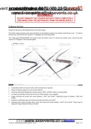
Figure 22. Non-Circular Gearing<br />
2. To install the intermediate pinion, align the arrows that<br />
are stamped on the pinion and liftwheel gear so they<br />
point toward each other.<br />
3. Check operation of gear train by rotating the pinion four<br />
(4) complete revolutions; liftwheel gear will turn one (1)<br />
complete revolution and the arrows will again be aligned<br />
as shown. If the arrows do not align or there is binding<br />
between the gear teeth, repeat the above steps.<br />
4. For gearing lubrication instruction, see page 16.<br />
FASTENERS<br />
Models B, C & F tighten motor housing cover screws (627-<br />
108) to where they have a minimum breakaway torque of<br />
5.423 Nm (48 pound inch) and the brake attaching screws<br />
(627-253) have a 5.649 Nm (50 pound inch) minimum breakaway<br />
torque.<br />
When removing or installing the lower hook pin (627-764),<br />
care must be taken so as to prevent damaging the pin<br />
and/or hook block. These pins are tapered groove pins and<br />
as a result, they can only be removed in one direction. To<br />
remove the pin, a V-Block, drift and hammer (or slow acting<br />
press) are required. The drift should be the same diameter<br />
as the pin (5/16” diameter (7.94mm) for Models B, C & F<br />
and 3/8” (9.52mm) diameter for Models J, L, R, LL & RR,<br />
and it should be placed on the small end of the pin. The<br />
small end of the pin is the end opposite the end on which the<br />
3 grooves are visible. Place the hook block in the V-Block<br />
and drive the pin out using the drift and a hammer or slow<br />
acting press.<br />
www.sxsevents.co.uk<br />
email: enquiries@sxsevents.co.uk<br />
Arrows Must Be<br />
Aligned As Shown<br />
Intermediate<br />
Pinion 627-325<br />
Liftwheel Gear<br />
627-303<br />
CAUTION<br />
AT ASSEMBLY ARROWS ON<br />
GEAR & PINION MUST LINE UP<br />
Liftwheel<br />
627-302<br />
Missing Tooth In<br />
Liftwheel Spline<br />
Missing Tooth Space<br />
In Liftwheel Gear<br />
Spline<br />
To re-install the pin, the parts must be arranged the same as<br />
they were when the pin was removed. To do this, use the<br />
small end of the pin as a gage. First check the holes in the<br />
hook block body and determine which hole is the largest.<br />
Place the hook body in the V-Block with the larger hole on<br />
top. Next, check each end of the hole in the lower hook<br />
chain block (627-775) and determine which end is the<br />
largest. Place the chain in the slot of the chain block and<br />
insert the chain block, with the large hole on top, into the<br />
hook block body. Align the holes in the hook block body with<br />
the hole in the chain block and insert the small end of the pin<br />
in the hole. Push the pin in by hande until it stops and then<br />
use a hammer or slow acting press to drive the pin into position<br />
so that the end of the pin is flush with the outside surace<br />
of the hook block body.<br />
V!<br />
WARNING<br />
Use of improper lower hook chain block pin as well as<br />
improper installation of the pin can cause the pin to break<br />
and allow the load to fall.<br />
TO AVOID INJURY AND PROPERTY DAMAGE:<br />
Use only <strong>CM</strong> supplied, special high strength lower hook<br />
chain block pin to attach the chain to the lower hook block<br />
and install the pin as directed above.<br />
Models J, L, R, LL & RR tighten limit switch bracket attaching<br />
screws (627-220), motor end bell attaching screws (627-<br />
411), brake attaching screws (627-253) and hexagonal brake<br />
stud (627-265) to where they have a minimum breakaway<br />
torque of 5.649 Nm (50 pound inch). The liftwheel gear nut<br />
(627-305) should be tighten to a seating torque of 115.245<br />
Nm (85 pound feet).<br />
www.sxsevents.co.uk<br />
22