Lighting - Trackspot Manual - SXS Events
Lighting - Trackspot Manual - SXS Events
Lighting - Trackspot Manual - SXS Events
- No tags were found...

You also want an ePaper? Increase the reach of your titles
YUMPU automatically turns print PDFs into web optimized ePapers that Google loves.
nd Audio-Visual Phone: courtesy 0870 of Services 080 2342mail: enquiries@sxsevents.co.ukwww.sxsevents.co.ukUser <strong>Manual</strong>High End Systems, Inc.2105 Gracy Farms LaneAustin, TX 78758 U.S.A.P/N 60600034 Version 4.1www.sxsevents.co.uk
nd Audio-Visual Phone: courtesy 0870 of Services 080 2342mail: enquiries@sxsevents.co.ukwww.sxsevents.co.ukwww.sxsevents.co.uk
nd Audio-Visual Phone: courtesy 0870 of Services 080 2342mail: enquiries@sxsevents.co.ukwww.sxsevents.co.ukUser <strong>Manual</strong>© High End Systems, Inc. 1997, All Rights ReservedInformation and Specifications in this document are subject to changewithout notice. High End Systems, Inc. assumes no responsibility orliability for any errors or inaccuracies that may appear in this manual.The system software for the Status Cue ® lighting console described inthis manual is furnished under a license agreement and may be used orcopied only in accordance with the terms of the agreement.<strong>Trackspot</strong> User <strong>Manual</strong>P/N 60600034 Version 4.1September 02, 1999Printed in the U.S.A.C.C.www.sxsevents.co.uk<strong>Trackspot</strong> User <strong>Manual</strong>i
International Salesnd Audio-Visual Phone: courtesy 0870 of Services 080 2342mail: enquiries@sxsevents.co.ukU.S. and the High End Systems, Inc. or High End Systems, Inc.Americas: 2105 Gracy Farms Lane 8200 Haskell AvenueAustin, TX 78758 Van Nuys, CA 91406www.sxsevents.co.ukUSAUSAvoice: (512) 836-2242 voice: (818) 947-0550FAX: (512) 837-5290 FAX: (818) 908-8975Europe:Singapore:World Wide Web:TrademarksHigh End Systems GmbHLohstrasse 22D-85445 SchwaigGermanyvoice: +49 8122 9903-0FAX: +49 8122 9903-33High End Systems Singapore Pte. Ltd.1 Tannery Road 06-05Cencon 1Singapore 1334voice: +65 742 8266FAX: +65 743 9322http://www.highend.comTrademarks used in this text: Lightwave Research and High EndSystems are registered trademarks; <strong>Trackspot</strong>, Status Cue, andIntellabeam are trademarks of High End Systems, Inc.Belden is a registered trademark of Belden, Inc. Philips is a registeredtrademark of Philips <strong>Lighting</strong> Company. Other trademarks and tradenames may be used in this document to refer to either the entitiesclaiming the marks and names or their products. High End Systemsdisclaims any proprietary interest in trademarks and trade namesowned by others.Patents<strong>Trackspot</strong> may use one or more of the following patents: US 4,962,687;US 5,078,039; UK 2,043,769; US 5,331,822; US 5,402,326; US D372550;UK 2292896; US D365165; US 5,430,629; US D360,404; US 5,455,748;0475082; US 5,506,762; M9604224.9; US 5,515,254; US D370080; UK2.291,814; US 5,545.951; UK 2055842; UK 2,292,530; UK 2294909; UK2292896; MR 8621996; and US 5,580,164.Additional patents pending.iiwww.sxsevents.co.uk<strong>Trackspot</strong> User <strong>Manual</strong>
Declaration of Conformityaccording to ISO/IEC Guide 22 and EN45104nd Audio-Visual Phone: courtesy 0870 of Services 080 2342mail: Manufacturer’s enquiries@sxsevents.co.ukwww.sxsevents.co.ukname: High End Systems, Inc.Manufacturer’s address: 2105 Gracy Farms LaneAustin, Texas 78758U.S.A.Distributor’s name:Distributor’s address:High End Systems, Inc.2105 Gracy Farms LaneAustin, Texas 78758U.S.A.Declares that the productProduct Name:Product Number:Product Options:<strong>Trackspot</strong><strong>Trackspot</strong>Allconforms to the following EEC directives:73/23/EEC, as amended by 93/68/EEC89/336/EEC, as amended by 92/31/EEC and 93/68/EECEquipment referred to in this declaration of conformity was firstmanufactured in compliance with the following standards in 1995:Safety: EN 60598-1 : 1993EN 60598-2-17 : 1989A1-A3 : 1993EMC:EN 55022, Class A ITEIEC 801-2, 1991 Level 2 (4/8 kV)IEC 801-3, Draft 5 Level 2 (3 V/m)IEC 801-4, 1988 Level 2 (1 kV/0.5 kV)www.sxsevents.co.ukU.S.A., September 02, 1999Lanny Derryberry, Compliance Engineer<strong>Trackspot</strong> User <strong>Manual</strong>iii
Important Safety Informationnd Instructions Audio-Visual Phone: courtesy pertaining to continued 0870 of protection Services 080 against fire, 2342electricshock, exposure to excessive ultraviolet (UV) radiation, and injury topersons are found in Appendix D.mail: enquiries@sxsevents.co.ukwww.sxsevents.co.ukPlease read all instructions prior to assembly, mounting, and operatingthis equipment.Important: Informations De SécuritéLes instructions se rapportant à la protection permanente contre lesincendies, l’électrocution, l’exposition à un rayonnement ultraviolet(UV) excessif et aux blessures corporelles se trouvent dans l’Annexe D.Veuillez lire toutes les instructions avant d’assembler, de monter oud’utiliser cet équipement.Wichtige SicherheitshinweiseSicherheitsanleitungen zum Schutz gegen Feuer, elektrischen Schlag,übermäßige UV-Strahlung und Verletzung von Personen finden Sie inAnhang D.Vor der Montage, dem Zusammenbau und der Inbetriebnahme diesesGeräts alle Anleitungen sorgfältig durchlesen.Informazioni Importanti Di SicurezzaLe istruzioni sulla protezione da incendi, folgorazione, esposizioneeccessiva a raggi ultravioletti (UV) e infortuni sono contenutenell’appendice D.Si prega di leggere tutte le istruzioni prima di assemblare, montare eazionare l’apparecchiatura.Informacion Importante De SeguridadEn el Apéndice D se encuentran instrucciones sobre proteccióncontinua contra incendios, descarga eléctrica, exposición excesiva aradiación ultravioleta (UV) y lesiones personales.Lea, por favor, todas las instrucciones antes del ensamblaje, montaje yoperación de este equipo.Warranty InformationLimited WarrantyUnless otherwise stated, your product is covered by a two-year partsand labor limited warranty. Dichroic filters are not guaranteed againstbreakage or scratches to coating. It is the owner’s responsibility tofurnish receipts or invoices for verification of purchase, date, andivwww.sxsevents.co.uk<strong>Trackspot</strong> User <strong>Manual</strong>
dealer or distributor. If purchase date cannot be provided, date ofmanufacture will be used to determine warranty period.nd Audio-Visual Phone: courtesy 0870 of Services 080 2342Returning an Item Under Warranty for Repairmail: It isenquiries@sxsevents.co.ukwww.sxsevents.co.uknecessary to obtain a Return Material Authorization (RMA)number from your dealer or point of purchase BEFORE any units arereturned for repair. The manufacturer will make the finaldetermination as to whether or not the unit is covered by warranty.Lamps are covered by the lamp manufacturer’s warranty.Any Product unit or parts returned to High End Systems must bepackaged in a suitable manner to ensure the protection of such Productunit or parts, and such package shall be clearly and prominentlymarked to indicate that the package contains returned Product units orparts and with a Return Material Authorization number. Accompanyall returned Product units or parts with a written explanation of thealleged problem or malfunction.Please Note:Freight<strong>Trackspot</strong> User <strong>Manual</strong>Freight Damage Claims are invalid for fixturesshipped in non-factory boxes and packing materials.All shipping will be paid by the purchaser. Items under warranty shallhave return shipping paid by the manufacturer only in the ContinentalUnited States. Under no circumstances will freight collect shipmentsbe accepted. Prepaid shipping does not include rush expediting suchas air freight. Air freight can be sent customer collect in theContinental United States.REPAIR OR REPLACEMENT AS PROVIDED FOR UNDER THISWARRANTY IS THE EXCLUSIVE REMEDY OF THE CONSUMER.HIGH END SYSTEMS, INC. MAKES NO WARRANTIES, EXPRESSOR IMPLIED, WITH RESPECT TO ANY PRODUCT, AND HIGH ENDSPECIFICALLY DISCLAIMS ANY WARRANTY OFMERCHANTABILITY OR FITNESS FOR A PARTICULAR PURPOSE.HIGH END SHALL NOT BE LIABLE FOR ANY INDIRECT,INCIDENTAL OR CONSEQUENTIAL DAMAGE, INCLUDING LOSTPROFITS, SUSTAINED OR INCURRED IN CONNECTION WITH ANYPRODUCT OR CAUSED BY PRODUCT DEFECTS OR THE PARTIALOR TOTAL FAILURE OF ANY PRODUCT REGARDLESS OF THEFORM OF ACTION, WHETHER IN CONTRACT, TORT (INCLUDINGNEGLIGENCE), STRICT LIABILITY OR OTHERWISE, ANDWHETHER OR NOT SUCH DAMAGE WAS FORESEEN ORUNFORESEEN.Warranty is void for unauthorized repairs or parts or if the product ismisused, damaged, or modified in any way. This warranty gives youspecific legal rights, and you may also have other rights which varyfrom state to state.www.sxsevents.co.ukv
FCC Informationnd Audio-Visual Phone: courtesy 0870 of Services 080 2342mail: enquiries@sxsevents.co.ukThis equipment has been tested and found to comply with the limits fora Class A digital device, pursuant to part 15 of the FCC rules. Theselimits are designed to provide reasonable protection against harmfulwww.sxsevents.co.ukinterference when the equipment is operated in a commercialenvironment. This equipment generates, uses, and can radiate radiofrequency energy and, if not installed and used in accordance with theinstruction manual, may cause harmful interference to radiocommunications. Operation of this equipment in a residential area islikely to cause harmful interference in which case the user will berequired to correct the interference at his own expense.Product Modification WarningHigh End Systems products are designed and manufactured to meetthe requirements of United States and International safety regulations.Modifications to the product could affect safety and render the productnon-compliant to relevant safety standards.Mise En Garde Contre La Modification Du ProduitLes produits High End Systems sont conçus et fabriquésconformément aux exigences des règlements internationaux desécurité. Toute modification du produit peut entraîner sa nonconformité aux normes de sécurité en vigueur.ProduktmodifikationswarnungDesign und Herstellung von High End Systemen entsprechen denAnforderungen der U.S.A. und den internationalenSicherheitsvorschriften. Abänderungen dieses Produktes könnendessen Sicherheit beeinträchtigen und u. U. gegen die diesbezüglichenSicherheitsnormen verstoßen.Avvertenza Sulla Modifica Del ProdottoI prodotti di High End Systems sono stati progettati e fabbricati persoddisfare i requisiti delle normative di sicurezza statunitensi edinternazionali. Qualsiasi modifica al prodotto potrebbe pregiudicare lasicurezza e rendere il prodotto non conforme agli standard di sicurezzapertinenti.Advertencia De Modificación Del ProductoLos productos de High End Systems están diseñados y fabricados paracumplir los requisitos de las reglamentaciones de seguridad de losEstados Unidos e internacionales. Las modificaciones al productopodrían afectar la seguridad y dejar al producto fuera de conformidadcon las normas de seguridad relevantes.viwww.sxsevents.co.uk<strong>Trackspot</strong> User <strong>Manual</strong>
Table of Contentsnd Audio-Visual Phone: courtesy 0870 of Services 080 2342Introductionmail: enquiries@sxsevents.co.ukwww.sxsevents.co.uk<strong>Trackspot</strong> ® Features ...................................................................... Intro-1Caution and Warning Symbols ..................................................... Intro-2Cautions .................................................................................. Intro-2Warnings ................................................................................. Intro-2Getting Help ................................................................................... Intro-3Specifications ................................................................................. Intro-4Model Information .................................................................. Intro-4Physical Specifications ........................................................... Intro-4Electrical Specifications ......................................................... Intro-4Environmental Specifications ................................................ Intro-5Cable and Connector Specifications ..................................... Intro-5DMX data cables ............................................................. Intro-5DMX data connectors ..................................................... Intro-5DMX data terminators .................................................... Intro-5Safety Specifications .............................................................. Intro-5Optional Accessories ..................................................................... Intro-6Chapter 1Setup and AssemblyUnpacking <strong>Trackspot</strong> ® ........................................................................ 1-1Saving the Shipping Materials ..................................................... 1-1Inspecting the Contents ............................................................... 1-1Installing the Yoke ............................................................................... 1-1Selecting the Voltage ........................................................................... 1-3Powering Up the Fixture ..................................................................... 1-3Understanding LED Indicators ........................................................... 1-4Fan LED ........................................................................................ 1-4Enable LED ................................................................................... 1-4Audio LED ..................................................................................... 1-4Chapter 2 Configuring Your <strong>Trackspot</strong> ®Choosing a Control Mode ................................................................... 2-1DMX 512 Protocol ........................................................................ 2-1LWR Protocol ................................................................................ 2-2Standard Analog ........................................................................... 2-2Stand Alone Operation (Master/Slave) ....................................... 2-2Enabling the Control Mode ................................................................. 2-3Personality Switches .................................................................... 2-3Address Switches .......................................................................... 2-6Installing Remote Enable/Disable ...................................................... 2-6SPST Switch .................................................................................. 2-7External Voltage Source .............................................................. 2-7Mountingwww.sxsevents.co.ukthe Fixture .......................................................................... 2-8<strong>Trackspot</strong> User <strong>Manual</strong>vii
nd Audio-Visual Phone: courtesy 0870 of Services 080 2342Additional Hardware .................................................................... 2-8Truss or Other Support System ............................................ 2-8Safety Cable ........................................................................... 2-9Clamp ..................................................................................... 2-9Obtaining Cabling and Terminators ................................................. 2-10mail:Constructingenquiries@sxsevents.co.ukwww.sxsevents.co.ukCabling ................................................................. 2-11Constructing Terminators .......................................................... 2-11Linking the Fixtures .......................................................................... 2-12DMX 512 Protocol ...................................................................... 2-12LWR Protocol .............................................................................. 2-14Standard Analog ......................................................................... 2-15Stand Alone Operation (Master/Slave) ..................................... 2-16Focusing the Fixture .......................................................................... 2-17Chapter 3General MaintenanceReplacing Parts .................................................................................... 3-1Replacing the Lamp ...................................................................... 3-1Replacing Power Supply Fuses ................................................... 3-4Replacing the Mirror Assembly ................................................... 3-6Replacing or Installing Custom Gobos ....................................... 3-7Cleaning Your <strong>Trackspot</strong> ® .................................................................. 3-9Cleaning the Outer Surfaces ........................................................ 3-9Cleaning the Internal Components ........................................... 3-10Removing the Color Wheel or Gobo Wheel ....................... 3-10Reinstalling the Color Wheel or Gobo Wheel .................... 3-12Adjusting Wheel Clearance ............................................................... 3-12Chapter 4TroubleshootingFixture does not work: no LEDs, fans, lamp, or otherfunctionality (fixture appears dead) ................................................... 4-1Lamp will not strike ............................................................................. 4-1Light output is low, beam edge is very soft, images fuzzy ............... 4-1Lamp shuts off ..................................................................................... 4-2Error tone (two level beeping) after the fixture homes .................... 4-2Yellow Enable LED or green Audio LED does not illuminate .......... 4-3Fixture does not respond to data ........................................................ 4-3Color wheel or gobo wheel is not centered in the beam or is inthe wrong position ............................................................................... 4-3None of the motors work and the yellow Enable LED does not illuminate4-4Appendix A DMX Control of <strong>Trackspot</strong> ®Start Channels and Construct Parameters ........................................A-1Low Resolution Mode ...................................................................A-1High Resolution Mode ..................................................................A-1viiiwww.sxsevents.co.uk<strong>Trackspot</strong> User <strong>Manual</strong>
Appendix B <strong>Trackspot</strong> ® MSpeed Timesnd Audio-Visual DMX Phone: courtesy 512 Protocol MSpeed 0870 Times of..................................................... Services 080 2342 B-1LWR Protocol MSpeed Times ............................................................. B-5mail: enquiries@sxsevents.co.ukwww.sxsevents.co.ukAppendix C Personality and AddressSwitch SettingsPersonality Switch Settings ................................................................C-1Address Switch Settings .....................................................................C-2Appendix D Important Safety InformationEnglish Version ....................................................................................D-1Appendice DIMPORTANTES INFORMATIONS SUR LA SÉCURITÉ ..................D-2Anhang DWICHTIGE HINWEISE FÜR IHRE SICHERHEIT ............................D-3Apéndice DINFORMACIÓN IMPORTANTE DE SEGURIDAD ...........................D-4Appendice DIMPORTANTI INFORMAZIONI PER LA SICUREZZA ....................D-5VIGTIG FIKKER HEDS INFORMATION - DANMARK .....D-6Glossary<strong>Trackspot</strong> User <strong>Manual</strong>List of FiguresFigure 1-1. Side view of <strong>Trackspot</strong> .................................................... 1-2Figure 1-2. Inserting the yoke screws and T-handles ...................... 1-2Figure 1-3. <strong>Trackspot</strong> rear panel ....................................................... 1-3Figure 1-4. LED location on the rear panel ...................................... 1-4Figure 2-1. Address and personality DIP switches .......................... 2-3Figure 2-2. Connecting a remote enable/disable switch to themaster fixture .................................................................. 2-7Figure 2-3. Attaching two C-clamps to the <strong>Trackspot</strong> yoke .......... 2-10Figure 2-4. Attaching a safety cable to the mounted fixture ......... 2-10Figure 2-5. XLR 3-pin connectors .................................................... 2-11Figure 2-6. Data cable terminator ................................................... 2-11Figure 2-7. Linking fixtures to a DMX 512 protocol controller .... 2-13Figure 2-8. Linking fixtures to a LWR protocol controller ............ 2-14Figure 2-9. Analog In connector ...................................................... 2-15Figure 2-10. Linking fixtures to a standard analog controller ...... 2-15Figure 2-11. Linking master and slave fixtures together ............... 2-16Figure 2-12. Lens tube adjustment .................................................. 2-17Figure 3-1. Underside of <strong>Trackspot</strong> ................................................... 3-2www.sxsevents.co.ukix
nd Audio-Visual Phone: courtesy 0870 of Services 080 2342Figure 3-2. Underside of <strong>Trackspot</strong> with access door removed ...... 3-2Figure 3-3. Proper way to handle a QT 8500 lamp ........................... 3-3Figure 3-4. Installing a new lamp ...................................................... 3-3Figure 3-5. Fuse locations on the circuit board ................................ 3-5Figure 3-6. Fuse housing location on the rear panel ........................ 3-5mail:Figure 3-7.enquiries@sxsevents.co.ukwww.sxsevents.co.ukMirror assembly ............................................................. 3-6Figure 3-8. Installing a new mirror ................................................... 3-6Figure 3-9. Custom gobo .................................................................... 3-7Figure 3-10. Gobo wheel and gobo wheel sensor location .............. 3-8Figure 3-11. Custom gobo aperture in gobo wheel .......................... 3-8Figure 3-12. <strong>Trackspot</strong> internal components .................................. 3-10Figure 3-13. Components of the color and gobo wheels ............... 3-11Figure 3-14. Pull wheel up and out to remove ................................ 3-11Figure 3-15. Sensor below each wheel ............................................ 3-11Figure 3-16. Homing slot on wheel ................................................. 3-11Figure 3-17. Allen screws on the color wheel and gobo wheelhubs ............................................................................. 3-13List of TablesTable Intro-1. <strong>Trackspot</strong> optional accessories ............................ Intro-6Table 2-1. Channel assignments ........................................................ 2-1Table 2-2. Personality switch settings - operating modes ............... 2-3Table 2-3. Personality switch settings - control modes .................... 2-5Table 2-4. Address switch settings .................................................... 2-6Table 3-1. Description and function of <strong>Trackspot</strong> fuses .................. 3-4Table 4-1. Symptoms and Solutions .................................................. 4-1Table A-1. Starting channels in 7-channel DMX 512 protocol ........A-2Table A-2. Construct parameters in DMX 512 low resolutionmode .................................................................................A-4Table A-3. Construct parameters in DMX 512 high resolutionmode .................................................................................A-5Table B-1. DMX 512 protocol MSpeed times ................................... B-1Table B-2. LWR protocol MSpeed times ...........................................B-5Table C-1. Personality switch settings for all control modes andoperating modes ..............................................................C-1Table C-2. Address switch settings for LWR protocol andmaster/slave mode ...........................................................C-2www.sxsevents.co.ukx<strong>Trackspot</strong> User <strong>Manual</strong>
Introductionnd Audio-Visual Phone: courtesy 0870 of Services 080 2342mail: enquiries@sxsevents.co.ukwww.sxsevents.co.ukCongratulations on your purchase of the <strong>Trackspot</strong> ® automatedluminaire. <strong>Trackspot</strong> is a versatile and affordable automated fixturethat outperforms any luminaire in its class. Superb engineering,precision optics, and a variety of control options makes <strong>Trackspot</strong> thebest value in low-cost intelligent lighting.The <strong>Trackspot</strong> color wheel features eight richly-saturated dichroiccolors (plus white) and a color corrector. The 10-position gobo wheelincludes two multi-colored dichroic patterns and a replaceable customgobo position. <strong>Trackspot</strong> has an ultra-fast, smooth pan and tiltcapability as well as optical sensors that eliminate color or gobopositioning errors. Control options include standard analog,Lightwave Research (LWR) protocol, and DMX 512 protocol.<strong>Trackspot</strong> is also fully functional with no controller at all (stand alonemode).<strong>Trackspot</strong> ® Features• Color wheel featuring eight dichroic colors plus color correctorand open (white)• Gobo wheel with eight unique patterns, including two multicoloreddichroic patterns, and a replaceable custom gobo position• Various control options, including stand alone operation, standardanalog, LWR protocol, and DMX 512 protocol• Precision stepper motors for pan and tilt movement• Optical sensor on color and gobo wheels to prevent positioningerrors• External voltage switch with selectable voltage for 100V, 120V,140V, 200V, 220V, or 240VAC at 50 or 60 Hz• Thermal overload protection• Multitap power transformer that provides over-voltagecompensations to help prevent surge-related problems• QT 8500 lamp specifically designed for use with <strong>Trackspot</strong>combining affordability, long lamp life (300 hour average),reliability, high output, and stable color temperature throughoutthe life of the lamp• Electronic circuit design for 100% dimming• Variable speed strobingwww.sxsevents.co.uk• 32 pre-programmed effects sequences<strong>Trackspot</strong> User <strong>Manual</strong> <strong>Trackspot</strong>® Features Intro-1
• Built-in condenser microphone that picks up ambient bass tond Audio-Visual trigger Phone: courtesy changes in the pre-programmed 0870 of Services 080 effects sequences2342• Easy, quick lamp replacement with no optimization needed• Remote system enable/disable using low voltage controlmail: enquiries@sxsevents.co.ukwww.sxsevents.co.uk• Break-resistant mirror• Pan and tilt invert option• Low power consumption: 3.1 A @120V, 1.55 A @240V• Complies with safety requirements in the USA, Canada, and theEuropean community.Caution and Warning SymbolsThe following international symbols appear in margins throughout thismanual to highlight caution and warning messages.CautionsNot heeding Caution messages could result in personal injury and/ordamage to equipment.Caution:This symbol appears adjacent to Cautionmessages.Hot Surface:This symbol indicates a hot surface.WarningsNot heeding Warning messages could result in serious personal injury.Warning:This symbol appears adjacent to high voltagewarning messages.Fire Hazard:This symbol indicates that a fire hazard ispresent.Eye Protection:This symbol indicates that eye protectionis required.1mMinimum Distance: This symbol indicates the minimumdistance to a lighted object, which inwww.sxsevents.co.ukthis case is 1 meter.Intro-2 Caution and Warning Symbols <strong>Trackspot</strong> User <strong>Manual</strong>
Getting Helpnd Audio-Visual Contact Phone: courtesy High End Systems 0870 Customer of Services080 in one 2342of the waysshown:mail: enquiries@sxsevents.co.ukwww.sxsevents.co.ukU.S., the Americas, Service address:and Europe: High End Systems, Inc.2105 Gracy Farms LaneAustin, TX 78758 USAFrom 8 a.m. to 6 p.m. (U.S. Central time)Monday through Friday: (800) 890-898924 hour FAX: (512) 834-919524 hour voice mail: (512) 837-3063(800) 890-8989orService address:High End Systems, Inc.8200 Haskell AvenueVan Nuys, CA 91406 USAFrom 8 a.m. to 5 p.m. (U.S. Pacific time)Monday through Friday: (818) 947-0550FAX: (818) 908-8975Singapore:High End Systems Singapore Pte. Ltd.1 Tannery Road 06-05Cencon 1Singapore 1334voice: +65 742 8266FAX: +65 743 932224-hour customer http://info.highend.com/service/service.htmlservice World WideWeb response:High End SystemsWorld Wide Website:http://www.highend.comwww.sxsevents.co.uk<strong>Trackspot</strong> User <strong>Manual</strong> Getting Help Intro-3
Specificationsnd Audio-Visual Phone: courtesy 0870 of Services 080 2342Model Informationmail: Model: enquiries@sxsevents.co.ukwww.sxsevents.co.uk<strong>Trackspot</strong>Manufacturer: Lightwave Research2105 Gracy Farms LaneAustin, TX 78758USADistributor:Product Number:High End Systems, Inc.2105 Gracy Farms LaneAustin, TX 78758USA<strong>Trackspot</strong>Physical SpecificationsDimensions (including yoke):Weight:Lamp type:655mm L x 297mm W x 254mm H(25.8” L x 11.7” W x 10” H)10.4 kg (23.0 lbs)Philips ® QT 8500, 250 W onlyElectrical SpecificationsFactory setting:Voltage rating:Power consumption:Rated power:Rated frequency:240 VAC100V, 120V, 140V, 200V, 220V, 240V3.5 A @ 100V2.9 A @ 120V2.5 A @ 140V1.75 A @ 200V1.6 A @ 220V1.5 A @ 240V350W50/60 HzPower factor: 120V, 60 Hz: 0.98240V, 50 Hz: 0.96Maximum winding temperature, Tw: 130° C (266° F)Maximum capacitor temperature, Tc: 85° C (185° F)Warning:Class I equipment - For continued protectionagainst electric shock connect this equipmentto an earthed (grounded) power source only.www.sxsevents.co.ukIntro-4 Specifications <strong>Trackspot</strong> User <strong>Manual</strong>
Environmental Specificationsnd Audio-Visual Maximum Phone: courtesy ambient temperature, 0870 of Ta: Services 080 50° C (122° 2342F)Maximum exterior surface temperature: 67° C (153° F)mail: Minimum enquiries@sxsevents.co.ukwww.sxsevents.co.ukdistance to lighted object: 1.0 meter (3.28 ft)Minimum distance to flammable objects: 1.0 meter (3.28 ft)Caution:Use in dry locations only.Warning:Do not mount on a flammable surface.Cable and Connector SpecificationsDMX data cablesBelden ® 9841 or equivalent (meets specifications for EIA RS-485applications) with the following characteristics:• 2-conductor twisted pair plus a shield• maximum capacitance between conductors - 30 pF/ft.• maximum capacitance between conductor and shield - 55 pF/ft.• maximum resistance of 20 / 1000 ft.• nominal impedance 100-140DMX data connectors3-pin male and female XLR connectorsDMX data terminatorsMale XLR connector with 120 ohm terminatorSafety SpecificationsSafety standards: EN 60598-1 : 1993EN 60598-2-17 : 1989A1-A3 : 1993EMC standards:EN 55022, Class A ITEIEC 801-2, 1991 Level 2 (4/8 kV)IEC 801-3, Draft 5 Level 2 (3 V/m)IEC 801-4, 1988 Level 2 (1 kV/0.5 kV)UL 153CSA 22.2 No. 12www.sxsevents.co.uk<strong>Trackspot</strong> User <strong>Manual</strong> Specifications Intro-5
Optional Accessoriesnd Table Audio-Visual Phone: 1-1 courtesy below lists the <strong>Trackspot</strong> 0870 of optional Services 080 accessories 2342available fromyour High End Systems dealer/distributor.mail: enquiries@sxsevents.co.ukwww.sxsevents.co.ukTable 1-1. <strong>Trackspot</strong> optional accessoriesPart DescriptionPart NumberStatus Cue <strong>Lighting</strong> Console 22020002Intellabeam LCD Controller 01020006Universal Controller 23020003<strong>Trackspot</strong> Special Analog Controller 16020001Modular Gobo wheel with tabs 99110017Custom GoboCall*QT-8500 <strong>Trackspot</strong> replacement lamp 55030036Keal road case, <strong>Trackspot</strong> (4 fixtures) 16070002Keal road case, <strong>Trackspot</strong> (4 fixtures and 1controller)1607000110' data cable, 3-pin XLR heavy duty 5505000525' data cable, 3-pin XLR heavy duty 5505000650' data cable, 3-pin XLR heavy duty 55050007100' data cable, 3-pin XLR heavy duty 55050008Galvanized safety cable with spring snap 12040001Deluxe C-clamp with silver powdercoat finish 55000004100' cable (for <strong>Trackspot</strong> Special Analog Controlleronly)50' cable (for <strong>Trackspot</strong> Special Analog Controlleronly)0705000107050002Interconnect cable extender 90409006Unprogrammed RAM card for Intellabeam LCD orUniversal controller80440017Call* - For more information about optional accessories, contact eitheryour High End Systems dealer/distributor, High End System Sales, orvisit the High End Systems Web site. For contact information, see“International Sales” on page ii.www.sxsevents.co.ukIntro-6 Optional Accessories <strong>Trackspot</strong> User <strong>Manual</strong>
Chapter 1nd Audio-Visual Setup Phone: courtesy and Assembly 0870 of Services 080 2342mail: enquiries@sxsevents.co.ukwww.sxsevents.co.uk 1Unpacking <strong>Trackspot</strong> ®Unpack your fixture and verify that it arrived complete and withoutany damage.Saving the Shipping MaterialsDo not discard the shipping carton and packing materials. The cartonand packing materials are specifically designed to protect the productduring transport.High End Systems assumes no responsibility for products that havebeen damaged during transport. Therefore, you should return aproduct for repair in its original shipping carton and packing materials.Note:Before sending anything to the factory, call your High EndSystems dealer/distributor for a Return MaterialAuthorization (RMA) number. The factory cannot acceptany goods shipped without an RA number.Inspecting the ContentsCarefully unpack the carton and inspect the contents for damage. Ifany of the items in the following list are missing or damaged, notifyboth the shipping agent and your sales agent immediately.• <strong>Trackspot</strong> fixture• set of five Philips ® QT 8500, 250 W lamps• yoke (yoke screws and T-handles are already installed on thefixture.)Installing the YokeYou will need:• 1/4 inch allen wrench• two 1/4 inch yoke screws*• two clamping T-handles*• yoke*www.sxsevents.co.uk*These items are shipped with the <strong>Trackspot</strong> fixture.<strong>Trackspot</strong> User <strong>Manual</strong> Unpacking <strong>Trackspot</strong>® 1-1
LIGHTWAVE RESE ARCHAUSTIN, TX U.S.A.LIGHTWAVE RESE ARCHAUS TIN, TX U.S.A.To install the yoke:1. Unplug the fixture. If the fixture has been operating, allow thend Audio-Visual Phone: courtesy 0870 of Services 080 2342fixture to cool for at least 5 minutes.mail: enquiries@sxsevents.co.ukwww.sxsevents.co.uk2. Place the fixture on a sturdy surface so you can easily access bothsides of the fixture.3. Remove the yoke screws and T-handles already installed in the<strong>Trackspot</strong> fixture (see Figure 1-1).yoke screwT-handleFigure 1-1. Side view of <strong>Trackspot</strong>4. Place the yoke ends over the fixture and align the yoke’s screwholes with the screw holes on the fixture (see Figure 1-2).Figure 1-2. Inserting the yoke screws and T-handles5. Replace the yoke screws through the round holes in each side ofthe yoke and tighten firmly.Caution:You must tighten the yoke screws firmly. Thefixture may fall from the yoke if it is notsecured.6. Replace the T-handles through the semi-circular opening in eachside of the yoke. The T-handles should not be very tight; you willadjust the T-handles when mounting the fixture.On the top of the yoke are three 13 mm (1/2 inch) diameter mountingholes used to mount the fixture. For more information, see the sectiontitled “Mounting the Fixture” on page 2-8.www.sxsevents.co.uk1-2 Installing the Yoke <strong>Trackspot</strong> User <strong>Manual</strong>
140DA TA INVO LT AGE S EL E CTWARNING: CHANGE VOLTAGE S ELECT ONLY WITH POWER REMOVED.CAUTION: HOT REMO VE PO WER BEFORE RELA MPINGWARNING: NOT FOR RESIDENTIAL USE. TO REDUCE THE RISK OFFIRE OR EL ECTRIC S HO CK , DO NOT E XPOSE TO RA IN OR MOIS TURE,NO USE R S ERV ICEABLE P ART S IN SID E. RE FE R SERVIC ING TOQUALI FIED SER VICE PERSO NNEL. FOR SAFE OP ERA TION CONS ULTUS ER MAN UAL.DA TA OUTTIL TMSPE EDGOBOAN ALOG I N0-10VAN ALOGGND1 4 2 86SH UTTERFUSECO LORPANDI MFAN24 VDCOUT(UNREG.)AD DRESS010203040506070809101112ENABLEINPU TSPECI AL ANALOGGND4251 386 7FO R FUTHER INFORMATIONCO N SULT USERS M ANU ALLIGHTWAVE RESEARCH2209 WEST BRAKER LANE , AUSTI N, TEXAS U .S.A.SWITCHESONnone121,231,32,31,2,341,42,41,2,4AD DRESS131415161718192021222324FO R FUR THER INFORMATIONPLEASECONSULT USER MANUALAD DR ESSSWITCHESON3,41,3,42,3,41,2,3,451,52,51,2,53,51,3,52,3,51,2,3,5PERSONALITYFIXT UR E MODE SW ITC HES 1-2NORMAL RUNSELF TE STSET- UP2LAMP SAVE1,2CO NTROL MODE SWITC HES 3 -8LIGHTWAVE CONTROLDM X 1-256DM X 257-512AN ALOGAU DI O (S LAVE)AU DI O (MA STER)PAN INVE RTTIL T INVE RTPERSONALITYSWITCHESONNO N E1NO N E544,53867FO R FUR THER INFORMATIONPLEASECONSULT USER MANUALAU DIOMICSelecting the Voltagend Audio-Visual <strong>Trackspot</strong> Phone: courtesy is factory set 0870 to 240 of volts. If Services 080 your power source 2342 is not 240volts, you must change the fixture’s input voltage. <strong>Trackspot</strong> willautomatically adjust to the appropriate frequency rating for anymail:voltageenquiries@sxsevents.co.ukwww.sxsevents.co.uksetting you select.1You will need:Warning:• wide tip, flat head screwdriverTo select the voltage:1. Unplug the fixture.Be sure to match the fixture’s selectablevoltage to your power source prior tooperating this equipment.2. Insert a flat head screwdriver into the slot on the voltage selectswitch located on the rear panel of the fixture (see Figure 1-3).3. Push the switch face in and turn until the line on the outer ring ispointed at the voltage that is equal to the power source you areusing (see Figure 1-3).240 volts selected voltage select switch200120240100220switch face140200120 240100 220trackspot ®outer ring537Figure 1-3. <strong>Trackspot</strong> rear panelIf the desired voltage is not listed on the voltage select switch,choose the next higher voltage. For example, if you have a 230 voltpower source, you must use the 240 volt setting.4. After setting the correct voltage, make sure that the switch face isflush with the outer ring (see Figure 1-3).Powering Up the FixtureUnlike other High End Systems lighting equipment, <strong>Trackspot</strong> does nothave a power switch. Powering up the fixture is as easy as plugging itinto a power source. However, it is very important that you unplug thewww.sxsevents.co.ukfixture before performing certain procedures as shown in this manual.<strong>Trackspot</strong> User <strong>Manual</strong> Selecting the Voltage 1-3
DATA INVOLTAGE SELECTWARNING: CHANGE VOLTAGE SELECT ONLY WI TH POWER REMOVED.CAU TION : HOT R EMOVE POW ER BEFORE RELAMPINGUSER MANUAL.DATA OUTTI LTMSP EEDGOB OANALOG IN0-10VANALOGGND7SHUTTERCOLORPANDIM24 VDCADDRESS010203040506070809101112GND4 2 51 386 7FOR FUTHER INFORMATIONCONSULT USERS MANUALnone121,231,32,31,2,341,42,41,2,42209 WEST BRAKER LANE, AUSTIN, TEXAS U.S.A.ADDRESS131415161718192021222324FOR FURTHER INFORMATIONPLEASE CONSULT USER MANUALPERSONALI TYFI XT URE MODE SWI TCHES 1-2SET-UPLAMP SAVE3,41,3,42,3,41,2,3,451,52,51,2,53,51,3,52,3,51,2,3,5CONTROL MODE SWITCHES 3-8SWITCHESON38Understanding LED Indicatorsnd Audio-Visual Phone: courtesy 0870 of Services 080 2342mail: enquiries@sxsevents.co.ukwww.sxsevents.co.ukThis section describes the LEDs (Light Emitting Diode) on the<strong>Trackspot</strong> rear panel: Fan, Enable, and Audio (see Figure 1-4). If youare experiencing problems with your <strong>Trackspot</strong> fixture, these LEDsmay provide insight on where the problem is originating. See “” onpage 4-1 for possible solutions to LED-related symptoms.140200120240WARNING: NOT FOR RESI DENTIAL USE. TO REDUCE THE RISK OFFIRE ORELECTRICSHOCK, DO NOTEXPOSE TO RAINOR MOISTURE,NO USERSERVI CEABLE PA RTS INSIDE. REFER SERVICING TOQUALIFI ED SERVI CE PERSONNEL. FOR SAFE OPERATION CONSULT100220FUSEFAN®trackspotENABLEONSWITCHESLI GHTWAVE RESEARCHADDRESSONSWITCHESPERSONALITYAUDIOMICFan LEDEnable LEDAudio LEDMODELSERIALFACTORY SET VACWATTSHZDATEQC61 4 2 853OUT(UNREG.)INPUTSPECIAL ANALOGNORMAL RUNSELF TESTLIGHTWAVE CONTROLDMX 1-256DMX 257-512ANALOGAUDIO (SLAVE)AUDIO (MASTER)PAN INVERTTI LT INVERTNONE121,2NONE544,5FOR FURTHER INFORMATIONPLEASE CONSULT USER MANUAL67Figure 1-4. LED location on the rear panelFan LEDThe red Fan LED monitors the voltage to the cooling fan. The Fan LEDilluminates when the fixture is first powered up, and stays illuminatedfor two minutes after the lamp is extinguished. <strong>Trackspot</strong> comesequipped with thermal overload protection to automatically extinguishthe lamp if the maximum temperature inside the fixture is exceeded. Ifthe fixture overheats, the Fan LED will flash four times, pause, andrepeat.Enable LEDThe yellow Enable LED monitors the power applied to the motors. TheEnable LED should be illuminated whenever the fixture is ON. If thelogic board is not receiving the 24 volts required to operate the fixture,the Enable LED will not illuminate.Audio LEDThe green Audio LED monitors the fixture’s response to sound. TheAudio LED illuminates when the fixture is ON and ambient bass isregistered, regardless of the configuration. (If the fixture is notprogrammed to receive audio bass frequencies, the sound trigger isignored.)www.sxsevents.co.uk1-4 Understanding LED Indicators <strong>Trackspot</strong> User <strong>Manual</strong>
Chapter 2Configuring courtesy Your of <strong>Trackspot</strong> ®nd Audio-Visual Phone: 0870 Services 080 2342mail: enquiries@sxsevents.co.ukwww.sxsevents.co.ukTo prepare your <strong>Trackspot</strong> for operation, you must choose a controlmode, set the personality and address switches, mount the fixture, linkthe fixture, and focus the fixture.Choosing a Control ModeThere are four different control modes that will operate your <strong>Trackspot</strong>fixture: DMX 512 protocol, LWR protocol, standard analog, and standalone operation (master/slave).When configured for DMX 512 protocol, LWR protocol, or stand aloneoperation, <strong>Trackspot</strong> uses seven contiguous digital channels to controlits constructs. When used with a standard analog controller, <strong>Trackspot</strong>uses either six or seven contiguous analog channels per fixture. Todetermine whether you will use six or seven analog channels, see“Standard Analog” on page 2-15. The digital/analog channels have thefunctions shown in Table 2-1 below:Table 2-1. Channel assignmentsChannelFeature1 Pan2 Tilt3 Color4 Gobo5 Shutter6 Dim7 MSpeed2DMX 512 ProtocolDMX 512 (D for digital, MX for multiplex and 512 is the number ofchannels per link) is a reliable and efficient control protocol.Developed by the United States Institute of Theatre Technology(USITT), DMX 512 is the standard method used in the lighting industryfor controlling lighting fixtures and other devices (such as hazers andlasers).A controller using DMX 512 protocol (such as the Status Cue ® <strong>Lighting</strong>Console) can control a large number of different types of devices madeby various equipment manufacturers, such as High End Systems, onthe same link.www.sxsevents.co.ukYou can control up to 72 <strong>Trackspot</strong>s per DMX 512 link in either low orhigh resolution mode. For more information on resolution modes, see“Start Channels and Construct Parameters” on page A-1.<strong>Trackspot</strong> User <strong>Manual</strong> Choosing a Control Mode 2-1
LWR Protocolnd Audio-Visual Phone: courtesy 0870 of Services 080 2342mail: enquiries@sxsevents.co.ukLightwave Research (LWR) protocol was created to enable 10-bitresolution for mirror positioning. Other control protocols (includingDMX 512) allow for only 8-bit resolution. LWR protocol controls HighEnd Systems www.sxsevents.co.ukfixtures only. Other vendors besides High End Systemshave controllers that support LWR protocol. Consult thedocumentation provided with your controller for information aboutprotocol support.The Intellabeam ® LCD Controller, Universal Controller, and theStatus Cue ® System, all manufactured by Lightwave Research, supportLWR protocol and can be used to control <strong>Trackspot</strong> fixtures. Consultthe documentation provided with your controller to determine thenumber of fixtures you can control per link.Standard Analog<strong>Trackspot</strong> can be controlled by any 0-10 volt analog controller.When operating under an analog controller, each fixture must beindividually attached to the controller. The controller sends analogoutput to each fixture that is connected to the controller. To determinethe number of fixtures per link that can be controlled by your analogcontroller, consult the documentation provided with your controller.Stand Alone Operation (Master/Slave)<strong>Trackspot</strong> can be fully functional without the use of a controller. Standalone operation, also called master/slave mode, uses one fixture(designated as the master) to control the other fixtures (designated asthe slaves). When operating in a master/slave mode, the masterfixture’s audio microphone registers ambient bass noise to advancethrough <strong>Trackspot</strong>’s 32 preset programs.For greater control of the preset programs while in master/slave mode,connect the master fixture to a <strong>Trackspot</strong> ® Special Analog Controller.You can wire <strong>Trackspot</strong> fixtures operating in master/slave mode forremote lamp enable/disable. For more information, see “InstallingRemote Enable/Disable” on page 2-6.www.sxsevents.co.uk2-2 Choosing a Control Mode <strong>Trackspot</strong> User <strong>Manual</strong>
DATA INVOLTAGE SELECTWARNING: CHANGE V OLTAGE SE LECT ONLY WI TH P OWER REMOVED.CAU TION : HOT R EMOVE POW ER BEFORE RELAMPINGWARNING: NOT FOR RESI DENTIAL USE. TO REDUCE THE RISK OFFIRE ORELECTRICSHOCK, DO NOTEXPOSE TO RAINOR MOISTURE,NO USERSERVI CEABLE PA RTS INSIDE. REFER SERVICING TODATA OUTTI LTMSP EEDGOB OANALOG IN0-10VANALOG6GND7SHUTTERCOLORPANDIM24 VDCOUT(UNREG.)41ADDRESS010203040506070809101112GNDFOR FUTHER INFORMATIONCONSULT USERS MANUAL2536872209 WEST BRAKER LANE, AUSTIN, TEXAS U.S.A.SWITCHESONnone121,231,32,31,2,341,42,41,2,4ADDRESS131415161718192021222324SWITCHESON3,41,3,42,3,41,2,3,451,52,51,2,53,51,3,52,3,51,2,3,5PERSONALI TYSWITCHESONFI XT URE MODE SWI TCHES 1-2NORMAL RUNNONELAMP SAVE1,2CONTROL MODE SWITCHES 3-8LIGHTWAVE CONTROL NONEDMX 1-2565DMX 257-5124ANALOG4,5AUDIO (SLAVE)3AUDIO (MASTER)8FOR FURTHER INFORMATIONPLEASE CONSULT USER MANUALEnabling the Control Modend Audio-Visual Phone: courtesy 0870 of Services 080 2342mail: enquiries@sxsevents.co.ukOnce you determine which control mode to use, you must set thefixture’s DIP switches to enable each <strong>Trackspot</strong> for that control modeand to assign fixture order (or starting channel). The personality andaddresswww.sxsevents.co.ukDIP switches (all factory set OFF) are located on the rear panelof the fixture (see Figure 2-1).140200120240100220®trackspotLI GHTWAVE RESEARCHaddress switches2QUALIFI ED SERVI CE PERSONNEL. FOR SAFE OPERATION CONSULTUSER MANUAL.FUSEpersonality switchesFOR FURTHER INFORMATIONPLEASE CONSULT USER MANUALFANENABLEADDRESSPERSONALITYAUDIOMICSELF TESTSET-UP121 4 2 853INPUTSPECIAL ANALOGPAN INVERTTI LT INVERT67For sample personality and address switch settings in each controlmode, see “Linking the Fixtures” on page 2-12.Personality SwitchesThe personality switch settings determine the fixture’s operating modeand/or control mode. See Table 2-2 below for a detailed description ofpersonality switch settings. For a quick-reference table of personalityswitch settings, see “Personality Switch Settings” on page C-1.Table 2-2. Personality switch settings - operating modesOperatingModesSelf TestFigure 2-1. Address and personality DIP switchesPersonalitySwitches ONPERSONALITY8 7 6 5 4 3 2 1onDescriptionStarts an internal self-diagnostic routinewhich verifies that the major functions ofthe fixture (pan, tilt, gobo wheel, colorwheel, and shutter) are working properly.The fixture performs its homing procedureonce (you will hear clattering sounds as theshutter and mirror seek their homeposition) and then repeats its self-test untilyou set switch 1 OFF.Note: Although a controller is not requiredfor the self-test, setting personality switch 1ON will override any controller that mightbe attached to the fixture.www.sxsevents.co.uk<strong>Trackspot</strong> User <strong>Manual</strong> Enabling the Control Mode 2-3
Table 2-2. Personality switch settings - operating modesnd Audio-Visual Phone: courtesy 0870 The fixture of performs Services 080 its homing 2342procedureand the lamp turns on, allowing you towww.sxsevents.co.ukadjust the focus.while in setup mode to select a goboSet Uppattern that helps you clearly see thePERSONALITY8 7 6 5 4 3 2 1effects of your focusing adjustments.(Focus)onNote: Although a controller is not requiredfor the self-test, setting personality switch 1ON will override any controller that mightbe attached to the fixture.For information on how to focus the fixture,see “Focusing the Fixture” on page 2-17.Increases the lamp life by lowering thePERSONALITY8 7 6 5 4 3 2 1onLamp Saveapplied voltage to the lamp by 10 percent.This setting will decrease light output andshould be used to compensate for high linevoltage.Auto DimOverride(LWR)PERSONALITY8 7 6 5 4 3 2 1 onAllows a fixture operating in LWR protocolto override the Auto Dim feature.The Auto Dim feature helps save the life ofthe lamp as follows: when the shuttercloses, the lamp stays on for 1.5 - 3.0minutes and then dims. When the shutteris re-opened, the lamp instantly returns toprogram intensity. Auto Dim occurs in allcontrol modes; however, this feature canbe overridden using LWR protocol whenthese personality switches are ON.PERSONALITYInverts the direction of the pan motor. Thissetting allows opposing fixtures to respondto mirror movement commands in thesame direction.Pan Invert 8 7 6 5 4 3 2 1onmail: enquiries@sxsevents.co.ukTilt InvertPERSONALITY8 7 6 5 4 3 2 1onInverts the direction of the tilt motor. Thissetting allows opposing or upside downfixtures to respond to mirror movementcommands in the same direction.www.sxsevents.co.uk2-4 Enabling the Control Mode <strong>Trackspot</strong> User <strong>Manual</strong>
Table 2-3. Personality switch settings - control modesnd Audio-Visual Phone: courtesy Personality 0870 of Services 080 2342ControlSwitchesDescriptionModesmail: enquiries@sxsevents.co.ukwww.sxsevents.co.ukONLowResolutionDMX mode(channels 1-256)LowResolutionDMX mode(channels257-512)HighResolutionDMX mode(channels 1-256)HighResolutionDMX mode(channels257-512)PERSONALITY8 7 6 5 4 3 2 1onPERSONALITY8 7 6 5 4 3 2 1onPERSONALITY8 7 6 5 4 3 2 1onPERSONALITY8 7 6 5 4 3 2 1onConfigures the fixture to receive DMXchannels 1-256 in low resolution mode.For more information, see “LowResolution Mode” on page A-1.Configures the fixture to receive DMXchannels 257-512 in low resolutionmode. For more information, see “LowResolution Mode” on page A-1.Configures the fixture to receive DMXchannels 1-256 in high resolutionmode. For more information, see “HighResolution Mode” on page A-1.Configures the fixture to receive DMXchannels 257-512 in high resolutionmode. For more information, see “HighResolution Mode” on page A-1.2LWR protocolPERSONALITY8 7 6 5 4 3 2 1onThe fixture must be controlled by LWRprotocol.StandardAnalogStand Alone(AudioMaster)Stand Alone(Audio Slave)PERSONALITY8 7 6 5 4 3 2 1onPERSONALITY8 7 6 5 4 3 2 1onPERSONALITY8 7 6 5 4 3 2 1onThe fixture must be controlled by a 0-10 volt standard analog controller.Configures the fixture for stand aloneoperation and designates the fixture asthe master. Also supplies power to thecontroller when used with the<strong>Trackspot</strong> Special Analog Controller.Only one fixture in a link may beselected as the master.Configures the fixture for stand aloneoperation and designates the fixture asa slave.www.sxsevents.co.uk<strong>Trackspot</strong> User <strong>Manual</strong> Enabling the Control Mode 2-5
Address Switchesnd The Audio-Visual address Phone: courtesy switch settings 0870 determine ofeither Services 080 the fixture’s 2342numericalorder in a link or its starting channel. The control mode you chosemail: determines how you set the address switches. See Table 2-4 foraddress enquiries@sxsevents.co.ukswitch www.sxsevents.co.uksettings.Table 2-4. Address switch settingsControl ModeDMX 512LWR ProtocolStandard AnalogStand Alone(Master/Slave)Address Switch SettingsSet each fixture’s address switches to its startingchannel using either high or low resolution mode(see Table A-1 on page A-2).Set each fixture’s address switches to represent thefixture’s sequential numerical order in the link (seeTable C-2 on page C-2).Set all address switches OFF.On the master <strong>Trackspot</strong> fixture, set the addressswitches to represent the total number of <strong>Trackspot</strong>fixtures in the link (including the master).On each slave fixture, set the address switches torepresent the fixture’s numerical order in the link.See Table C-2 on page C-2 for address switchsettings.Installing Remote Enable/DisableIf your <strong>Trackspot</strong> fixtures are operating in stand alone mode, you canremotely enable/disable the fixtures by installing either a remote SPSTswitch or an external voltage source.Warning:Unplug the fixture before installing remoteenable/disable.You will need:• either a SPST (single-pole, single-throw) switch or a 10 volt source(such as a battery, a 0-10 volt analog control source, etc.)• suitable length of 18-24 gauge two-conductor wire (The gauge ofconductor you need will depend on the distance from your remoteswitch or external voltage source to the master fixture.)• one male 8-pin DIN connectorwww.sxsevents.co.uk2-6 Installing Remote Enable/Disable <strong>Trackspot</strong> User <strong>Manual</strong>
DATA INDATA OUTVOLTAGE SELECTWARNING: CHANGE VOLTAGE SELECT ONLY WI TH POWER REMOVED.CAU TION : HOT R EMOVE POW ER BEFORE RELAMPINGUSER MANUAL.TI LTMSP EEDGOB OANALOG IN0-10VANALOGGND7SHUTTERCOLORPANDIM24 VDCOUT(UNREG.)ADDRESS010203040506070809101112SPECIAL ANALOGINPUTGND4 2531687FOR FUTHER INFORMATIONCONSULT USERS MANUAL2209 WEST BRAKER LANE, AUSTIN, TEXAS U.S.A.SWITCHESONnone121,231,32,31,2,341,42,41,2,4ADDRESS131415161718192021222324FOR FURTHER INFORMATIONPLEASE CONSULT USER MANUALPERSONALI TYFI XT URE MODE SWI TCHES 1-2SET-UPLAMP SAVESWITCHESON3,41,3,42,3,41,2,3,451,52,51,2,53,51,3,52,3,51,2,3,5SWITCHESON21,2CONTROL MODE SWITCHES 3-8LIGHTWAVE CONTROL NONEDMX 1-2565DMX 257-5124ANALOG4,5AUDIO (SLAVE)386TI LT INVERT7FOR FURTHER INFORMATIONPLEASE CONSULT USER MANUALSPST Switchnd Audio-Visual Phone: courtesy Note: Connect only 0870 the master of fixture Services 080 to the SPST 2342 switch.To install an SPST switch:mail: enquiries@sxsevents.co.ukwww.sxsevents.co.uk1. Unplug the fixture.2. Locate the female Analog In connector on the rear panel of themaster <strong>Trackspot</strong> fixture (see Figure 2-2).4 2 51 8 36 7140200120240WARNING: NOT FOR RESI DENTIAL USE. TO REDUCE THE RISK OFFI RE OR E LECTRI C SHOCK, DO NOT EXPOSE TO RAIN OR MOISTURE,NO USERSERVICEABLE PARTS INSIDE. REFER SERVICI NG TOQUALIFI ED SERVI CE PERSONNEL. FOR SAFE OPERATION CONSULT100220FUSEFAN®trackspotENABLELI GHTWAVE RESEARCHADDRESSPERSONALITYAUDIOMIC2NORMAL RUNSELF TESTNONE1OFFONMODELSERIALFACTORY SET VACWATTSHZDATEQC1 4 2 6853AUDIO (MASTER)PAN INVERTremote SPST switchAnalog In ConnectorFigure 2-2. Connecting a remote enable/disable switch tothe master fixture3. Connect DIN pin 1 and pin 5 together (see Figure 2-2). You canconnect these pins either at the fixture or in the male 8-pin DINconnector.4. Connect DIN pin 1 and pin 3 to the SPST switch (see Figure 2-2).When correctly connected to the SPST switch, the fixtures will beenabled when the circuit is closed and disabled when the circuit isopen.External Voltage SourceNote:Connect only the master fixture to the external voltagesource.To install an external voltage source:1. Unplug the fixture.2. Locate the Analog In female connector on the rear panel of themaster <strong>Trackspot</strong> fixture (see Figure 2-2).www.sxsevents.co.uk3. Connect analog DIN pin 1 and pin 5 together (see Figure 2-2). Youcan connect these pins either at the fixture end or in the male 8-pinDIN connector.<strong>Trackspot</strong> User <strong>Manual</strong> Installing Remote Enable/Disable 2-7
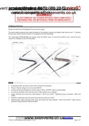
4. Connect analog DIN pin 2 to the negative voltage and analog DINpin 3 to the positive voltage using the conductor.nd Audio-Visual Phone: courtesy 0870 of Services 080 2342When correctly connected to the external voltage source, the fixtureswill be enabled when you apply 10 to 40 volts DC on pin 3. The fixturesmail: will be disabled enquiries@sxsevents.co.ukwww.sxsevents.co.ukwhen you apply zero volts DC on pin 3.Mounting the Fixture<strong>Trackspot</strong> is designed to be mounted in any orientation. Beforemounting the fixture, follow the precautions and suggestions below:• Verify the input voltage you are using matches the <strong>Trackspot</strong>fixture’s voltage selection switch. Unplug the fixture beforeturning the voltage select switch. See “Specifications” on pageIntro-4 and “Selecting the Voltage” on page 1-3 for moreinformation.• When you mount or position the fixture, make sure that noobstacles cover or block the fixture’s cooling fan intake (see Figure3-1 on page 3-2). A blocked airpath could result in damage to thefixture.Heed the following warnings to guard against personal injury anddamage to the fixture.Caution:Equipment suitable for dry locations only.Do not expose this equipment to rain ormoisture.1mWarnings: 1) Do not mount on a flammable surface.2) Maintain a minimum distance of 1.0meter (3.28 feet) from combustiblematerials.3) Maintain a minimum distance of 1.0meter (3.28 feet) from lighted object.This means the fixture must bepositioned at least 1 meter away fromthe object it is illuminating.Additional HardwareTo mount the fixture, you will need a truss or other support system, oneor more safety cables, and one or more clamps.Truss or Other Support SystemIf you are mounting the fixture on a truss or another type of support,verify the truss or support will handle the weight of all the devices youare mounting. The <strong>Trackspot</strong> fixture weight is listed inwww.sxsevents.co.uk“Specifications” on page Intro-4.2-8 Mounting the Fixture <strong>Trackspot</strong> User <strong>Manual</strong>
Safety CableHigh End Systems strongly recommends that you use safety cablend Audio-Visual Phone: courtesy 0870 of Services 080 2342when mounting any fixture. You must supply your own safety cableand verify the cable is capable of supporting the weight of the<strong>Trackspot</strong> www.sxsevents.co.ukfixture. You can order galvanized safety cables from yourHigh End Systems dealer/distributor (see “Optional Accessories” onpage Intro-6).mail: enquiries@sxsevents.co.ukClampYou must supply your own clamp(s) and verify the clamp is capable ofsupporting the weight of the <strong>Trackspot</strong> fixture. You can order deluxeC-clamps for a two-inch truss from your High End Systems dealer/distributor (see “Optional Accessories” on page Intro-6).2Caution: Make sure the fixture cannot be rotated 360°.(Using two clamps is a good way to make surethe fixture cannot be rotated in a full circle.)Allowing the fixture to rotate 360° couldloosen the clamp mounting bolts and causethe fixture to fall from its clamp.Note:Due to the wide variety of possible lighting designs, HighEnd Systems cannot make specific mountingrecommendations. Consider the following procedure as asuggested guideline only.Suggested mounting procedure:1. Unplug the fixture. If the fixture has been operating, allow thefixture to cool for at least 5 minutes.2. Use two people to mount each <strong>Trackspot</strong> fixture: one person tohold the fixture while it is being secured in place, and one personto the secure the fixture to its support and attach safety cables.3. Always stand on a firm, stable surface when mounting a fixture toits support. The fixture should be at a height where you cancomfortably work on it, and should either be resting on a stablesurface, or held in a stable manner. Do not allow one person toboth support and mount the fixture.4. Attach suitable clamp(s) through the holes on top of the yoke. Ifyou are attaching one clamp, use the middle hole on the yoke. Ifyou are attaching two clamps (as shown in Figure 2-3), attach oneclamp to each of the two outer holes on the yoke. Use lockingwashers when attaching the clamp(s) to the yoke.www.sxsevents.co.uk<strong>Trackspot</strong> User <strong>Manual</strong> Mounting the Fixture 2-9
Constructing Cablingnd Audio-Visual Phone: courtesy 0870 of Services 080 2342mail: enquiries@sxsevents.co.ukIf you need to construct cabling, you must use a shielded, twoconductorcable with a male 3-pin XLR connector on one end and afemale 3-pin XLR connector on the other end. Pin one is the shield(ground), www.sxsevents.co.ukpin two is the data complement (negative), and pin three isthe data true (positive) (see Figure 2-5). For more information oncabling and connector specifications, see “Specifications” on pageIntro-4.2Figure 2-5. XLR 3-pin connectorsYou should test each cable with a voltage/ohm meter (VOM) to verifycorrect polarity and to make sure that the negative and positive pinsare not grounded or shorted to the shield or to each other. Also, makesure that pin 1 is shielded.Caution:Do not use the ground lug on the XLRconnectors. Do not connect the shield toground or allow contact to ground.Grounding the shield could cause a groundloop and/or erratic behavior.Constructing TerminatorsIf you chose to use standard analog control, you do not need to attach aterminator to the last device on each link. However, for all othercontrol modes, the last device on each link must have a 120 ohm, 1/4watt (minimum) terminator attached to its Data Out connector.You can construct terminators by following the instructions below:1. Obtain a male XLR connector.2. Disassemble the connector.3. Solder a 120 ohm resistor, minimum of 1/4watt, between pins 2 and 3 (see Figure 2-6).www.sxsevents.co.uk4. Reassemble the XLR connector.5. Install the terminator in the Data Outconnector of the last fixture in the link.Figure 2-6. Datacable terminator<strong>Trackspot</strong> User <strong>Manual</strong> Obtaining Cabling and Terminators 2-11
Linking the Fixturesnd Audio-Visual Phone: courtesy 0870 of Services 080 2342mail: enquiries@sxsevents.co.ukThe control mode you use (DMX 512 protocol, LWR protocol, standardanalog, or stand alone operation) determines how you will link thefixtures to a controller with data cabling. If you decided to use standwww.sxsevents.co.ukalone operation with no controller, the master fixture serves as thecontroller for linking purposes. Follow the instructions listed below forlink information corresponding to the control mode you chose.DMX 512 ProtocolIf you chose DMX 512 protocol as your control mode, you must operateyour fixtures either in low resolution or high resolution. Controloptions available on your DMX controller will determine whether youcan operate your fixtures in low or high resolution mode. For moreinformation, see “Start Channels and Construct Parameters” on pageA-1.To link <strong>Trackspot</strong> fixtures using a controller with DMX 512 protocol,follow the steps listed below:1. On all fixtures, set the address switches to the appropriate DMX512 start channel and set the personality switches to enable eitherlow or high resolution mode.For personality and address switch settings in DMX 512 protocol,see Table A-1 on page A-2.2. Link the DMX 512 controller and fixtures together with 3-pin XLRtwo-conductor data cables. Plug the male end of a data cable intothe Data Out connector on the rear panel of the controller. Plugthe female end of that data cable into the Data In connector of thefirst fixture. Continue using this method to link the remainder ofthe fixtures together (see Figure 2-7).www.sxsevents.co.uk2-12 Linking the Fixtures <strong>Trackspot</strong> User <strong>Manual</strong>
Focusing the Fixturend Audio-Visual Once Phone: courtesy you have mounted 0870 and linked ofthe Services 080 fixtures together, 2342 you mustfocus each fixture. <strong>Trackspot</strong> has a manual focus which cannot beadjusted by a controller.mail: enquiries@sxsevents.co.ukwww.sxsevents.co.ukTo focus the fixture:1. Place the fixture in setup (focus) mode by setting personalityswitch 2 ON.2. Power up the fixture. The fixture performs its homing operationand turns on the lamp. (During the homing operation you will hearclattering sounds as the wheels, shutter, and mirror seek theirhome position.)3. <strong>Manual</strong>ly swivel the mirror until the beam is pointed at a flatsurface you intend to illuminate.4. Toggle address switch 1 ON and OFF to select a gobo pattern thathelps you clearly see the effects of your focusing adjustments.5. Loosen the lens adjustment thumbscrew and carefully slide thelens tube in and out while watching the beam projected on the flatsurface (see Figure 2-12). When the beam has a sharp edge,tighten the thumbscrew to secure the lens tube in place.2slide lens tube in and outmirrorlenstubelens adjustmentthumbscrewFigure 2-12. Lens tube adjustmentCaution:You must tighten the lens adjustmentthumbscrew firmly. The lens tube may fallfrom the fixture if it is not secured.www.sxsevents.co.uk<strong>Trackspot</strong> User <strong>Manual</strong> Focusing the Fixture 2-17
nd Audio-Visual Phone: courtesy 0870 of Services 080 2342mail: enquiries@sxsevents.co.ukwww.sxsevents.co.ukwww.sxsevents.co.uk2-18 <strong>Trackspot</strong> User <strong>Manual</strong>
Chapter 3General courtesy Maintenance ofnd Audio-Visual Phone: 0870 Services 080 2342mail: enquiries@sxsevents.co.ukwww.sxsevents.co.ukThis section includes information on replacing parts, installing customgobos, and cleaning your fixture.Caution:This fixture must be serviced by qualifiedpersonnel. The information listed in thissection is intended to assist qualifiedpersonnel only.Replacing PartsThis section explains how to remove and replace parts inside thefixture. Please note the warnings under each heading before servicingyour fixture.Replacing the Lamp3You will need:• Philips ® QT 8500 250 W lamp (p/n 55030036)• protective eyewear• leather gloves• isopropyl alcohol wipe(s)Caution:Warning:This equipment is designed for use with aPhilips ® QT 8500 250 W lamp only. Use of anyother type of lamp may be hazardous and mayvoid the warranty.An operating, unshielded QT 8500 lamp emitsultraviolet and visible (UV-vis) radiationwhich could damage eyes and skin. Wheneveryou are working on or near an exposed QT8500 lamp, wear protective eye gear. Neverlook directly at the lamp while the lamp is on.To replace the lamp:1. Unplug the fixture. If the fixture has been operating, wait at least 5minutes for the lamp to cool before handling.www.sxsevents.co.uk2. Put on your protective eyewear and leather gloves.3. Turn the fixture over so you can easily access its underside.<strong>Trackspot</strong> User <strong>Manual</strong> Replacing Parts 3-1
4. Remove the fixture’s access door by sliding the thumb latch towardthe rear of the fixture and lifting the door off (see Figure 3-1).nd Audio-Visual Phone: courtesy 0870 of Services 080 2342thumb latch cooling fan intakemail: enquiries@sxsevents.co.ukwww.sxsevents.co.ukaccess doorsafety cable connection pointon inside surfaceFigure 3-1. Underside of <strong>Trackspot</strong>The access door is connected to the fixture by a safety cable. Youcan leave the door attached, or you can unclip the safety cables tocompletely remove the door from the fixture.5. Locate the reflector, lamp socket, and old QT 8500 lamp (seeFigure 3-2). To remove the existing QT 8500 lamp, reach inside thereflector and carefully pull the lamp straight out of the socket. Liftthe old lamp out of the reflector and discard.reflectorQT 8500 lampsocketFigure 3-2. Underside of <strong>Trackspot</strong> with access door removedCaution:Do not squeeze the lamp glass when removingthe old lamp from the socket. Lamp glass mayshatter.www.sxsevents.co.uk3-2 Replacing Parts <strong>Trackspot</strong> User <strong>Manual</strong>
nd Audio-Visual Servicesmail: enquiries@sxsevents.co.uk6. Open the QT 8500 lamp box andplastic wrapper base pinsPhone: courtesy remove the lamp in its plasticwrapper. Carefully 0870 open the of end of080 2342the wrapper so that only the twolamp base pins are exposed (seewww.sxsevents.co.ukFigure 3-3). Hold the lamp within itsQT-8500 lampwrapper to avoid touching the lampglass. If you accidently touch the Figure 3-3. Proper way tolamp glass, clean it with an isopropyl handle a QT 8500 lampalcohol wipe.Caution:When handling the QT 8500 lamp, avoidcontact with the lamp glass. If the lamp glassis soiled by oil or dirt from skin, gloves, etc.,clean the cold lamp glass with an alcoholwipe. A soiled lamp could overheat and burst,causing damage to the fixture.7. Holding the lamp by its wrapper, insert the lamp in the reflectoruntil the base pins extend through the rear opening of the reflector(see Figure 3-4). Continue guiding the lamp until the two base pinsare firmly seated in the lamp socket and touching the ceramic stop(see Figure 3-4).3reflectorbasepinslampsocketceramicstopFigure 3-4. Installing a new lampRemove and discard the plastic wrapper. You do not need to optimizethe lamp because the <strong>Trackspot</strong> fixture uses a self-aligning lampsocket.If you disconnected the access door from the fixture, reconnect thesafety cable to the access door. Replace the access door and secure thethumb latch. Do not remove your protective eyewear or leathergloves until the access door is in place.www.sxsevents.co.uk<strong>Trackspot</strong> User <strong>Manual</strong> Replacing Parts 3-3
Replacing Power Supply Fusesnd Audio-Visual Phone: courtesy 0870 of Services 080 2342This section explains how to replace the fuses located on the <strong>Trackspot</strong>circuit board and rear panel.mail: You will enquiries@sxsevents.co.ukwww.sxsevents.co.ukneed:• flat head screwdriver (to replace the rear panel fuse only)• replacement fuse (see Table 3-1 for type and sizes)Caution:Warning:When operating, equipment surfaces mayreach temperatures up to 67° C (153° F).Allow 5 minutes for the fixture to cool beforehandling.Replace fuses only with the specified typeand rating.To replace the fuse:1. Unplug the fixture. If the fixture has been operating, allow thefixture to cool as described above.2. Determine which fuse(s) to replace by referring to Table 3-1 below.Table 3-1. Description and function of <strong>Trackspot</strong> fusesFuseLocationType andRatingSize Protects SymptomF1F2F3F4circuitboardcircuitboardcircuitboardrear panel5.0 A, 250V,Fast BlowOnly.125 A,250V, FastBlow Only.125 A,250V, FastBlow Only4.0 A, 250V,Slow BlowOnly5mm x20 mm5mm x20 mm5mm x20 mm5mm x20 mmAll MotorsData LinkData LinkMainPowerInputNo motors work.Yellow EnableLED does notlight.No response todata link.No response todata link.No power. Unitappears dead.3. Replace the fuse(s) with a fuse of the same type and rating.To access the fuses on the circuit board, remove the fixture’saccess door and locate the fuse to be replaced (see Figure 3-5).After replacing the appropriate fuse(s), replace the fixture’s accessdoor and secure the thumb latch.www.sxsevents.co.uk3-4 Replacing Parts <strong>Trackspot</strong> User <strong>Manual</strong>
DATA INVOLTAGE SELECTWARNING: CHANGE VOLTAGE SELECT ONLY WI TH POWER REMOVED.CAUTION:HOTREMOVE POWER BEFORE RELAMPINGWARNING: NOT FOR RESIDENTIAL USE. TO REDUCE THE RISK OFFI RE OR E LECTRI C SHOCK, DO NOT EXPOSE TO RAIN OR MOISTURE ,NO USERSERVI CEABLE PART S INSIDE. REFER SERVICING TODATA OUTTI LTMSP EEDGOB OANALOG IN0-10VANALOGGNDSHUTTERCOLORPANDIM24 VDCOUT(UNREG.)41ADDRESS010203040506070809101112GNDFOR FUTHER INFORMATIONCONSULT USERS MANUAL2536872209 WEST BRAKER LANE, AUSTIN, TEXAS U.S.A.SWITCHESONnone121,231,32,31,2,341,42,41,2,4ADDRESS131415161718192021222324PERSONALI TYSWITCHESONFI XT URE MODE SWI TCHES 1-2NORMAL RUNNONELAMP SAVESWITCHESON3,41,3,42,3,41,2,3,451,52,51,2,53,51,3,52,3,51,2,3,51,2CONTROL MODE SWITCHES 3-8LIGHTWAVE CONTROL NONEDMX 1-2565DMX 257-5124ANALOG4,5AUDIO (SLAVE)3AUDIO (MASTER)8FOR FURTHER INFORMATIONPLEASE CONSULT USER MANUALF1 Fusend Audio-Visual Phone: courtesy 0870 of 5.0 A, 250 Services 080 V, Fast Blow Only2342mail: enquiries@sxsevents.co.ukwww.sxsevents.co.ukF3 Fuse.125 A, 250 V,Fast Blow OnlyF2 Fuse.125 A, 250 V,Fast Blow OnlyFigure 3-5. Fuse locations on the circuit boardTo access the fuse on the rear panel, locate the fuse housing on therear panel (see Figure 3-6). Insert a flat head screwdriver in theslot on the fuse housing and push in and turn until the fusehousing pops out of the rear panel. After replacing the F4 fuse,insert the fuse housing in the rear panel. Use the screwdriver topush in and turn until the fuse housing is flush with the outer ring.3F4 fuse housing140200120240100220® ®trackspotLI GHTWAVE RESEARCHouterringQUALIFI ED SERVI CE PERSONNEL. FOR SAFE OPERATION CONSULTUSER MANUAL.FUSEFOR FURTHER INFORMATIONPLEASE CONSULT USER MANUALFANENABLEADDRESSPERSONALITYAUDIOMICMODELSERIALFACTORY SET VACWATTSHZDATEQC1 4 2 68537INPUTSPECIAL ANALOGSELF TESTSET-UPPAN INVERTTI LT INVERT1267Figure 3-6. Fuse housing location on the rear panelwww.sxsevents.co.uk<strong>Trackspot</strong> User <strong>Manual</strong> Replacing Parts 3-5
Replacing the Mirror Assemblynd Audio-Visual Phone: courtesyCaution: Use0870cautionofwhenServiceshandling080broken2342glass.!Glass shards are extremely sharp.mail: enquiries@sxsevents.co.ukwww.sxsevents.co.ukYou will need:• replacement mirror assembly (p/n 80180001) (see Figure 3-7)• leather gloves• 7/64-inch allen wrenchTo replace the mirror assembly:1. Unplug the fixture.2. Put on your leather gloves.3. Use a 7/64-inch allen wrench to remove thetwo allen screws that secure the mirrorassembly to the motor (see Figure 3-8). Setthe screws aside.4. Remove the old mirror assembly and carefullydiscard the broken glass.5. Open the boxcontaining the newmirror and carefullyremove the mirrorassembly from its foampackaging.6. Place the new mirrorassembly over thespring plunger andmotor shaft. Align thescrew holes on the newmirror assembly withthe screw holes on themotor. Replace the twoallen screws. Use theallen wrench to tightenthese screws securely.motorallenscrewsmirrorassemblyspring plungerFigure 3-7.Mirror assemblymotor shaftFigure 3-8. Installing a new mirrorCaution:You must tighten the two allen screws firmly.The mirror assembly may fall from the fixtureif it is not secured.www.sxsevents.co.uk3-6 Replacing Parts <strong>Trackspot</strong> User <strong>Manual</strong>
Replacing or Installing Custom Gobosnd Audio-Visual Phone: courtesyCaution:0870If the fixtureofhasServices 080been operating,2342allow thefixture at least 5 minutes to cool beforemail: enquiries@sxsevents.co.ukwww.sxsevents.co.ukhandling.The <strong>Trackspot</strong> gobo wheel includes one open position for a customgobo patterns. This allows you to install any gobo pattern you choose.(An optional gobo wheel with nine open positions for custom gobos(p/n 99110017) is also available from your High End Systems dealer/distributor.)The recommended custom goboshould be made of stainless steeland have a single notch on theedge for easy installation (seeFigure 3-9). The custom goboshould be between 0.1mm (0.004inches) and 0.3mm (0.012 inches)thick with a diameter of 25mm(0.984 inches).3To install a gobo:Figure 3-9. Custom gobo1. Unplug the fixture. If the fixture has been operating, allow thefixture to cool as described above.2. Turn the fixture over so you can easily access its underside.3. Remove the fixture’s access door by sliding the thumb latch towardthe rear of the fixture and lifting the door off.The access door is connected to the fixture by a safety cable. Youcan leave the door attached, or you can unclip the safety cables tocompletely remove the door from the fixture.4. Locate the gobo wheel and gobo wheel sensor (see Figure 3-10).Handle the gobo wheel carefully. If you accidently bend the gobowheel, it may rub against and damage the sensor. If the wheel isrubbing against the sensor or any other internal component, see“Adjusting Wheel Clearance” on page 3-12.www.sxsevents.co.uk<strong>Trackspot</strong> User <strong>Manual</strong> Replacing Parts 3-7
front of fixturend Audio-Visual Phone: courtesy 0870 of Services 080 2342mail: enquiries@sxsevents.co.ukwww.sxsevents.co.ukgobo wheel sensorgobo wheelFigure 3-10. Gobo wheel and gobo wheel sensor location5. <strong>Manual</strong>ly rotate the gobo wheel until the custom gobo position is atthe top of the wheel. The custom gobo position is identified by thethree tabs on the outer edge of the aperture (see Figure 3-11).custom gobo position6. Carefully slide the custom gobo under two of the three tabs. If thegobo has a notch, align the notch with the last tab, press the goboin place, and turn the gobo until the notch and the tab are nolonger aligned. If the gobo does not have a notch asrecommended, you must carefully apply pressure to the free sideof the custom gobo until it bows enough to slide under the thirdtab.Note:Figure 3-11. Custom gobo aperture in gobo wheelIf the custom gobo has letters or numbers, install the goboso that the information is legible when looking at the gobofrom the front of the fixture (see Figure 3-10).7. Reconnect the safety cable (if applicable), replace the access doorand secure the thumb latch.For more information about <strong>Trackspot</strong> custom gobos, contact eitheryour High End Systems dealer/distributor, High End System Sales, orvisit the High End Systems Web site. For contact information, see thesection titled “International Sales” on page ii.www.sxsevents.co.uk3-8 Replacing Parts <strong>Trackspot</strong> User <strong>Manual</strong>
Cleaning Your <strong>Trackspot</strong> ®nd Audio-Visual Phone: courtesy 0870 of Services 080 2342mail: enquiries@sxsevents.co.ukHow often you clean your <strong>Trackspot</strong> depends on the environment. Ifyour fixture is used in a dusty/oily environment, you should clean yourfixture once a month. A clean fixture helps maintain performance andreliability,www.sxsevents.co.uksince dust and dirt can accumulate and cause loss of lightoutput, overheating, and/or malfunctions.Cautions: 1) If the fixture has been operating, allow thefixture at least 5 minutes to cool beforehandling.Warning:2) Use only a low-pressure compressed airsource (25 psi or lower)3) To avoid personal injury, do not exposeyour eyes or skin to the direct jet ofcompressed air, since it can constitute aserious health hazard. Use suitableprotection for your eyes and exposed skin.Unplug the fixture before cleaning.3To thoroughly clean your <strong>Trackspot</strong>, you will need:• a soft, lint-free cotton cloth• mild glass cleaning solution• vacuum• soft dusting brush or low-pressure compressed air source• 1/4-inch wrench• cotton swabCleaning the Outer SurfacesWipe the outer surfaces with a soft cloth or use a vacuum to remove thedust and dirt. Vacuum dirt from the cooling fan air vents; do not use ablower to clean the fan, since this will force dirt into the fixture.To clean the fixture’s lens and mirror, apply a small amount of mildglass cleaning solution to a clean, soft cloth and gently wipe the lensand mirror surfaces.Note:Make sure to clean both sides of the lens glass. To accessthe inside of the lens tube glass, loosen the adjustmentthumbscrew and remove the lens tube from the fixture.See Figure 2-12 on page 2-17 to locate the lens tube andadjustment thumbscrew.www.sxsevents.co.ukYou must refocus the fixture after removing the lens tube.For information on focusing the fixture, see “Focusing theFixture” on page 2-17.<strong>Trackspot</strong> User <strong>Manual</strong> Cleaning Your <strong>Trackspot</strong>® 3-9
Cleaning the Internal Componentsnd Audio-Visual Phone: courtesy 0870 of Services 080 2342mail: enquiries@sxsevents.co.ukRemove the fixture’s access door by sliding the thumb latch toward therear of the fixture and lifting the door off. The access door isconnected to the fixture by a safety cable. You can leave the doorattached, www.sxsevents.co.ukor you can unclip the safety cable to completely remove thedoor from the fixture.Wipe the inner surfaces with a soft cloth or use a vacuum to remove thedust and dirt. If you use a vacuum on the fan, stabilize the fan bladeswith an object (not your finger!), such as a pen or a screwdriver, toprevent the fan from spinning (see Figure 3-12). Allowing the fan tospin with the force of the compressed air could damage the fan.Locate the power lens, stepper motors, gobo wheel, color wheel,sensors, shutter, hot mirror, and reflector (see Figure 3-12).powerlenscolorwheelshutterhotmirrorfanstepper motors gobo wheel sensors reflectorFigure 3-12. <strong>Trackspot</strong> internal componentsClean the stepper motors, shutter, and reflector with a soft dustingbrush or low-pressure compressed air source to remove accumulateddirt and dust.Clean the hot mirror and power lens with a soft cloth and mild glasscleaning solution.To clean the color wheel, gobo wheel, and their sensors, you mustremove each wheel from the fixture. Follow the procedures below toremove, clean, and reinstall each wheel.Removing the Color Wheel or Gobo WheelFor this procedure, you will need a 1/4-inch wrench.www.sxsevents.co.ukNote:Be careful not to scratch the dichroic filter glass on thewheels by scraping against other objects inside the fixture.3-10 Cleaning Your <strong>Trackspot</strong>® <strong>Trackspot</strong> User <strong>Manual</strong>
To remove either the color or gobo wheel:1. <strong>Manual</strong>ly rotate the wheel until the two 1/4-inch hex screws arend Audio-Visual Phone: courtesy 0870 of Services 080 2342pointed up and the large ends of the keyhole slots are pointeddown (see Figure 3-13).mail: enquiries@sxsevents.co.ukwww.sxsevents.co.ukFigure 3-13. Components of the color and gobo wheels2. Holding the wheel inplace, loosen, but do notremove these two hexscrews using a 1/4-inchwrench.3. Pull up on the wheel toslide the large ends of thekeyhole slot over the hexscrew heads, and pull outto remove the wheel (seeFigure 3-14).Locate the sensor below thewheel (see Figure 3-15).Gently clean the sensor’sgroove with either a cottonswab dipped in mild glasscleaner or with compressedair.Clean the dichroic filters orgobos on the wheel with a mildglass cleaner and a clean, softcloth. Make sure the wheel’shoming slot is free of dust anddirt (see Figure 3-16).Figure 3-14. Pull wheel up and outto removegrooveFigure 3-15. Sensor below each wheelFigure 3-16. Homing slot on wheelwww.sxsevents.co.uk3<strong>Trackspot</strong> User <strong>Manual</strong> Cleaning Your <strong>Trackspot</strong>® 3-11
Reinstalling the Color Wheel or Gobo Wheel1. Hold the wheel so that the large ends of the keyhole slots arend Audio-Visual Phone: courtesy 0870 of Services 080 2342pointed down and the adhesive used to hold glass to the wheel isfacing away from the lamp.mail: enquiries@sxsevents.co.ukwww.sxsevents.co.ukDichroic glass is attached to both the gobo wheel and color wheel.On one side of the wheel, you can clearly see the adhesive used toattach the glass. On the other side of the wheel, you see only theglass (no adhesive).Caution:You must replace the wheel so that theadhesive used to hold the glass to the wheel isfacing away from the lamp, otherwise, theheat from the lamp could melt the adhesiveand cause the glass to fall from the wheel.2. Place the bottom of the wheel in the sensor groove. Carefully slipthe large ends of the keyhole slots over the hex screws. Push thewheel in then down until the hex screws are in the narrow ends ofthe keyhole slots.3. Tighten the hex screws while holding the wheel in place. Tightenthe screws only until they are snug; do not overtighten.4. <strong>Manual</strong>ly rotate the wheel and note any contact between the wheeland its sensor. If there is contact, remove the wheel and lay it on aflat surface to determine if the wheel is warped. If the wheel iswarped, contact High End Systems customer service (see “GettingHelp” on page Intro-3). If the wheel is not warped, adjust thewheel’s clearance to the sensor. For more information, see“Adjusting Wheel Clearance” on page 2-12.When you have successfully cleaned the fixture’s internal components,reconnect the safety cable (if applicable), replace the access door, andsecure the thumb latch.Adjusting Wheel ClearanceAdjust the wheel clearance to prevent either the color or gobo wheelfrom making contact with its sensor or any other object in the<strong>Trackspot</strong> fixture.Before you adjust the wheel clearance, remove the wheel and lay it on aflat surface to determine if the wheel is warped (see “Removing theColor Wheel or Gobo Wheel” on page 3-10.) If the wheel is warped,contact High End Systems customer service (see “Getting Help” onpage Intro-3).www.sxsevents.co.ukIf the wheel is not warped, reinstall the wheel and follow the procedurebelow to adjust the wheel clearance (see “Reinstalling the Color Wheelor Gobo Wheel” on page 3-12.)3-12 Adjusting Wheel Clearance <strong>Trackspot</strong> User <strong>Manual</strong>
You will need:• 7/64 inch allen wrench (preferably with a long handle)nd Audio-Visual Phone: courtesy 0870 of Services 080 2342To adjust the wheel clearance:mail: enquiries@sxsevents.co.ukwww.sxsevents.co.uk1. Unplug the fixture. If the fixture has been operating, allow thefixture to cool for at least 5 minutes before handling.2. Remove the fixture’s access door and locate the color and gobowheels (see Figure 3-17).3. <strong>Manual</strong>ly rotate the wheel and note where the wheel contacts anyother object.4. Loosen, but do not remove, the two allen screws located on thewheel’s hub (see Figure 3-17).motor shaftcolor wheel3hubscrewsmotor shaftgobo wheelFigure 3-17. Allen screws on the color wheel and gobo wheel hubs5. Press on the center of the wheel to move the hub back and forth onthe motor shaft. Position the wheel so that it does not makecontact with its sensor or any other object as it turns.6. Tighten the allen screws while holding the wheel in place. Tightenthe screws only until they are snug; do not overtighten.When you have successfully adjusted the wheel clearance, reconnectthe safety cable (if applicable), replace the access door, and secure thethumb latch.www.sxsevents.co.uk<strong>Trackspot</strong> User <strong>Manual</strong> Adjusting Wheel Clearance 3-13
nd Audio-Visual Phone: courtesy 0870 of Services 080 2342mail: enquiries@sxsevents.co.ukwww.sxsevents.co.ukwww.sxsevents.co.uk3-14 <strong>Trackspot</strong> User <strong>Manual</strong>
Chapter 4Troubleshootingnd Audio-Visual Phone: courtesy 0870 of Services 080 2342mail: enquiries@sxsevents.co.ukwww.sxsevents.co.ukThis chapter lists typical symptoms and solutions for problems youmight experience when using your <strong>Trackspot</strong>. If you need additionalhelp, or if the problem you are experiencing is not listed in this section,contact your High End Systems dealer/distributor or High End SystemsCustomer Service in one of the ways shown in the section titled“Getting Help” on page Intro-3.Caution:This fixture must be serviced by qualifiedpersonnel. The information listed in thissection is intended to assist qualifiedpersonnel only.Table 4-1. Symptoms and SolutionsProblem Possible Cause Possible SolutionFixture does notwork: no LEDs,fans, lamp, orotherfunctionality(fixture appearsdeadLamp will notstrikeLight output islow, beam edgeis very soft,images fuzzyNo input powerBad lampIncorrect voltagesettingLamp not fullyseated in socket.Dichroic filters,mirror, reflector,and/or lenses dirty.a. Verify the fixture is plugged intoa working power supply.b. Replace the rear panel fuse.For more information, see“Replacing Power SupplyFuses” on page 3-4.Replace lamp with new or verifiedworking lamp.Make sure the fixture is set for thesame voltage as the power outlet.For more information, see“Selecting the Voltage” on page1-3.Make sure the lamp base pins arecorrectly inserted in the socket andtouch the ceramic stop. For moreinformation, see “Replacing theLamp” on page 3-1.Clean the lens tube, mirror,reflector, and dichroic filter glass.For more information, see“Cleaning the Outer Surfaces” onpage 3-9 and “Removing the ColorWheel or Gobo Wheel” on page3-10.www.sxsevents.co.uk4<strong>Trackspot</strong> User <strong>Manual</strong> 4-1
Table 4-1. Symptoms and Solutionsnd Audio-Visual Problem Phone: courtesy Possible 0870 CauseofServices 080 Possible Solution 2342a. Check the air forwww.sxsevents.co.ukrestricted air flow due to dustand dirt.b. Clean the fan and verify the fanis working. For moreLamp shutsOFFFixture isoverheated.(Another symptom:Fan LED will flashfour times, pause,and repeat.)information, see “Cleaning theOuter Surfaces” on page 3-9.c. Reduce the ambienttemperature around yourfixture. Maximum ambienttemperature for <strong>Trackspot</strong> is50° C (122° F).If your fixture overheats, you mustunplug the fixture, wait for thefixture to cool, then reconnect thepower supply to reset the fixture.Aging lampReplace lamp with a new orverified working lamp. For moreinformation, see “Replacing theLamp” on page 3-1.Incorrectpersonality switchsetting.Verify that the personality switchsetting you chose for your controlmode is correct. For moreinformation, see “PersonalitySwitches” on page 2-3.a. Clean the sensor and homingslot. For more information, see“Removing the Color Wheel orGobo Wheel” on page 3-10.Error tone (twolevel beeping)b. <strong>Manual</strong>ly rotate the wheel andnote any contact between theafter the fixturewheel and any other internalhomesGobo or color component. If the wheel iswheel not homing. warped, contact High EndSystems customer service (see“Getting Help” on page Intro-3).If the wheel is not warped,adjust the wheel clearance. Formore information, see“Adjusting Wheel Clearance” onpage 3-12.mail: enquiries@sxsevents.co.ukwww.sxsevents.co.uk4-2 <strong>Trackspot</strong> User <strong>Manual</strong>
Table 4-1. Symptoms and Solutionsnd Audio-Visual Phone: Problem courtesy Possible 0870 Cause of Services 080 Possible 2342SolutionMake sure the voltage selectYellow EnableThe voltage select switch is flush with the outer ring.LED www.sxsevents.co.ukor greenswitch is not seated For more information, seeAudio LED doescorrectly.“Selecting the Voltage” on pagenot illuminate1-3.a. Replace the XLR cables withnew or known working cables.Faulty XLR cable orincorrect cablelinking.b. Verify that the XLR cables havebeen correctly linked to thefixture. For more information,see “Linking the Fixtures” onpage 2-12.Verify that the controller is correctlyFixture does notrespond to dataThere is nocontroller attachedto the link, or thecontroller is notgenerating anyoutput.attached to the link (if applicable)and that the controller is able togenerate output to a knownworking fixture. For moreinformation, see “Specifications”on page Intro-4 or “Linking theFixtures” on page 2-12.a. Verify that the personalityswitch settings you chose foryour control mode are correct.b. Verify that the address switchIncorrectsettings you chose for thepersonality setting.fixture order or starting channelare correct. For moreinformation, see “Enabling theControl Mode” on page 2-3.Replace the F2 and/or F3 fuses onA fuse is blown.the circuit board. For moreinformation, see “Replacing PowerSupply Fuses” on page 3-4.Clean the sensor and homing slot.Sensor or homingslot is dirty.For more information, see“Removing the Color Wheel orColor wheel orGobo Wheel” on page 3-10.gobo wheel isnot centered inthe beam or isin the wrong Wheel is rubbingIf the wheel is warped, contactHigh End Systems customerservice (see “Getting Help” onpage Intro-3). If the wheel is notposition against sensor. warped, adjust the wheelclearance. For more information,see “Adjusting Wheel Clearance”www.sxsevents.co.ukon page 3-12.mail: enquiries@sxsevents.co.uk<strong>Trackspot</strong> User <strong>Manual</strong> 4-34
Table 4-1. Symptoms and Solutionsnd Audio-Visual Problem Phone: courtesy Possible 0870 CauseofServices 080 Possible Solution 2342None of themotors workReplace the F4 rear panel fusewww.sxsevents.co.ukand the yellowand the F1 circuit board fuse. ForA fuse is blown.Enable LEDmore information, see “Replacingdoes notPower Supply Fuses” on page 3-4.illuminatemail: enquiries@sxsevents.co.ukwww.sxsevents.co.uk4-4 <strong>Trackspot</strong> User <strong>Manual</strong>
Appendix ADMX courtesy Control of of<strong>Trackspot</strong> ®nd Audio-Visual Phone: 0870 Services 080 2342mail: enquiries@sxsevents.co.ukwww.sxsevents.co.ukUnder DMX 512 protocol, each <strong>Trackspot</strong> fixture uses a block of sevencontiguous DMX channels for a total of 72 fixtures per link. Althoughyou can control <strong>Trackspot</strong> from any DMX starting channel you choose,that starting channel must not interfere with another fixture’s channelblock.The tables below assume that all <strong>Trackspot</strong> fixtures will be assigned tothe same link, one after another. Keep in mind, however, that if youmix different devices on the same link, those devices will have differentchannel blocks that may overlap the 7-channel sequence listed below.Note:The values displayed in the tables in this appendix mayvary slightly depending on your controller’s roundingconvention.Start Channels and Construct ParametersIf you chose DMX 512 protocol as your control mode, you must operateyour <strong>Trackspot</strong> fixture(s) either in low resolution or high resolution.Control options available on your DMX controller will determinewhether you can operate your fixtures in low or high resolution mode.Low Resolution ModeLow resolution mode is used with DMX controllers that do not supportcolor or gobo fader and spin effects. There are fewer color and gobofeatures available in low resolution mode.High Resolution ModeHigh resolution mode has more construct parameters and is intendedfor DMX controllers with more accurate faders or direct numericalcontrol of each dim channel. In high resolution mode, the color faderand gobo fader effects include half colors, oscillating colors, color spineffects, and gobo spin effects.After determining which DMX 512 mode you will operate in, see TableA-1 for information such as DMX starting channels and address andpersonality switch settings in both high and low resolution modes. Forconstruct parameters available in low resolution mode, see Table A-2.For construct parameters available in high resolution mode, see TableA-3.www.sxsevents.co.ukA<strong>Trackspot</strong> User <strong>Manual</strong> Start Channels and Construct Parameters A-1
nd Table Audio-Visual Phone: A-1. courtesy Starting channels 0870 in 7-channel of ServicesDMX 080 512 protocol 2342mail: enquiries@sxsevents.co.ukwww.sxsevents.co.ukNumericalOrder InLinkAddressDIP SwitchesONPersonality DIPSwitches ONLow HighResolution ResolutionFixture 1 none 5 3, 5 001Fixture 2 1, 2, 3 5 3, 5 008Fixture 3 2, 3, 4 5 3, 5 015Fixture 4 1, 3, 5 5 3, 5 022Fixture 5 3, 4, 5 5 3, 5 029Fixture 6 1, 2, 6 5 3, 5 036Fixture 7 2, 4, 6 5 3, 5 043Fixture 8 1, 5, 6 5 3, 5 050Fixture 9 4, 5, 6 5 3, 5 057Fixture 10 1, 2, 3, 4, 5, 6 5 3, 5 064Fixture 11 2, 3, 7 5 3, 5 071Fixture 12 1, 3, 4, 7 5 3, 5 078Fixture 13 3, 5, 7 5 3, 5 085Fixture 14 1, 2, 4, 5, 7 5 3, 5 092Fixture 15 2, 6, 7 5 3, 5 099Fixture 16 1, 4, 6, 7 5 3, 5 106Fixture 17 5, 6, 7 5 3, 5 113Fixture 18 1, 2, 3, 5, 6, 7 5 3, 5 120Fixture 19 2, 3, 4, 5, 6, 7 5 3, 5 127Fixture 20 1, 3, 8 5 3, 5 134Fixture 21 3, 4, 8 5 3, 5 141Fixture 22 1, 2, 5, 8 5 3, 5 148Fixture 23 2, 4, 5, 8 5 3, 5 155Fixture 24 1, 6, 8 5 3, 5 162Fixture 25 4, 6, 8 5 3, 5 169Fixture 26 1, 2, 3, 4, 6, 8 5 3, 5 176Fixture 27 2, 3, 5, 6, 8 5 3, 5 183Fixture 28 1, 3, 4, 5, 6, 8 5 3, 5 190Fixture 29 3, 7, 8 5 3, 5 197Fixture 30 1, 2, 4, 7, 8 5 3, 5 204Fixture 31 2, 5, 7, 8 5 3, 5 211Fixture 32 1, 4, 5, 7, 8 5 3, 5 218Fixture 33 6, 7, 8 5 3, 5 225Fixture 34 1, 2, 3, 6, 7, 8 5 3, 5 232Fixture 35 2, 3, 4, 6, 7, 8 5 3, 5 239Fixture 36 1, 3, 5, 6, 7, 8 5 3, 5 246*Fixture 37 none 4 3, 4 257DMXStartingChannelwww.sxsevents.co.ukA-2 Start Channels and Construct Parameters <strong>Trackspot</strong> User <strong>Manual</strong>
Table A-1. Starting channels in 7-channel DMX 512 protocolnd Audio-Visual Phone:NumericalcourtesyAddress0870 ofPersonality Services 080 DIP 2342DMXSwitches ONOrder In DIP SwitchesLink ON Low High Startingwww.sxsevents.co.uk ChannelResolution Resolutionmail: enquiries@sxsevents.co.ukFixture 38 1, 2, 3 4 3, 4 264Fixture 39 2, 3, 4 4 3, 4 271Fixture 40 1, 3, 5 4 3, 4 278Fixture 41 3, 4, 5 4 3, 4 285Fixture 42 1, 2, 6 4 3, 4 292Fixture 43 2, 4, 6 4 3, 4 299Fixture 44 1, 5, 6 4 3, 4 306Fixture 45 4, 5, 6 4 3, 4 313Fixture 46 1, 2, 3, 4, 5, 6 4 3, 4 320Fixture 47 2, 3, 7 4 3, 4 327Fixture 48 1, 3, 4, 7 4 3, 4 334Fixture 49 3, 5, 7 4 3, 4 341Fixture 50 1, 2, 4, 5, 7 4 3, 4 348Fixture 51 2, 6, 7 4 3, 4 355Fixture 52 1, 4, 6, 7 4 3, 4 362Fixture 53 5, 6, 7 4 3, 4 369Fixture 54 1, 2, 3, 5, 6, 7 4 3, 4 376Fixture 55 2, 3, 4, 5, 6, 7 4 3, 4 383Fixture 56 1, 3, 8 4 3, 4 390Fixture 57 3, 4, 8 4 3, 4 397Fixture 58 1, 2, 5, 8 4 3, 4 404Fixture 59 2, 4, 5, 8 4 3, 4 411Fixture 60 1, 6, 8 4 3, 4 418Fixture 61 4, 6, 8 4 3, 4 425Fixture 62 1, 2, 3, 4, 6, 8 4 3, 4 432Fixture 63 2, 3, 5, 6, 8 4 3, 4 439Fixture 64 1, 3, 4, 5, 6, 8 4 3, 4 446Fixture 65 3, 7, 8 4 3, 4 453Fixture 66 1, 2, 4, 7, 8 4 3, 4 460Fixture 67 2, 5, 7, 8 4 3, 4 467Fixture 68 1, 4, 5, 7, 8 4 3, 4 474Fixture 69 6, 7, 8 4 3, 4 481Fixture 70 1, 2, 3, 6, 7, 8 4 3, 4 488Fixture 71 2, 3, 4, 6, 7, 8 4 3, 4 495Fixture 72 1, 3, 5, 6, 7, 8 4 3, 4 502**Note:Channels 253 - 256 and channels 509 - 512 cannot be useddue to <strong>Trackspot</strong>’s 7-channel block structure.www.sxsevents.co.uk<strong>Trackspot</strong> User <strong>Manual</strong> Start Channels and Construct Parameters A-3A
Table A-2. Construct parameters in DMX 512 low resolution modend Audio-Visual Phone: courtesy 0870 of Services 080 2342DMXLow ResolutionFunctionChannelParameters Decimal Percent Hexmail: enquiries@sxsevents.co.ukwww.sxsevents.co.uk1 Pan Pan Positioning, 8 bit 0-255 0-100 00-ffh2 Tilt Tilt Positioning, 8 bit 0-255 0-100 00-ffh34ColorWheelGoboWheel5 Shutteropen / color 1color 2color 3color 4color 5color 6color 7color 8color 9color 10open / gobo 1gobo 2gobo 3gobo 4gobo 5gobo 6gobo 7gobo 8gobo 9gobo 10closedopenstrobe 1strobe 2strobe 3strobe 4strobe 5strobe 6strobe 7closedopen03254791101381602002102400325479110138160200210240026517710212815317920423024201321314355637882940132131435563788294010203040506070809095020364F6E8AA0C8D2F0020364F6E8AA0C8D2F001A334D668099B3CCE6F26 Dimmer closed-open 0-255 0-100 00-ffh7 MSpeed slowest-fastest 0-255 0-100 00-ffhwww.sxsevents.co.ukA-4 Start Channels and Construct Parameters <strong>Trackspot</strong> User <strong>Manual</strong>
nd Audio-Visual Phone: courtesy 0870 of Services 080 2342Table A-3. Construct parameters in DMX 512 high resolution modeDMXHigh ResolutionFunctionChannelParameters Decimal Percent Hexmail: enquiries@sxsevents.co.ukwww.sxsevents.co.uk1 Pan Pan Positioning, 8 bit 0-255 0-100 00-ffh2 Tilt Tilt Positioning, 8 bit 0-255 0-100 00-ffh3ColorWheelopen / color 1forward color spin 8forward color spin 7forward color spin 6forward color spin 5forward color spin 4forward color spin 3forward color spin 2forward color spin 1reverse color spin 8reverse color spin 7reverse color spin 6reverse color spin 5reverse color spin 4reverse color spin 3reverse color spin 2reverse color spin 1half color 2color 2half color 3color 3half color 4color 4half color 5color 5half color 6color 6half color 7color 7half color 8color 8half color 9color 9half color 10color 10half color 1open / color 10815223036435159647179879499107112120128133140148156163168176184191196204212219224232240247252<strong>Trackspot</strong> User <strong>Manual</strong> Start Channels and Construct Parameters A-50369121417202325283134373942444750525558616466697275778083868891949799www.sxsevents.co.uk08F161E242B333B40474F575E636B707880858C949CA3A8B0B8BFC4CCD4DBE0E8F0F7FCA
Table A-3. Construct parameters in DMX 512 high resolution modend DMX Audio-Visual Phone: courtesy High 0870 Resolution of Services 080 2342FunctionDecimal Percent HexChannelParametersmail: enquiries@sxsevents.co.ukwww.sxsevents.co.uk4GoboWheel5 Shutteropen / gobo 1forward gobo spin 7forward gobo spin 6forward gobo spin 5forward gobo spin 4forward gobo spin 3forward gobo spin 2forward gobo spin 1reverse gobo spin 7reverse gobo spin 6reverse gobo spin 5reverse gobo spin 4reverse gobo spin 3reverse gobo spin 2reverse gobo spin 1gobo 2gobo 3gobo 4gobo 5gobo 6gobo 7gobo 8gobo 9gobo 10open / gobo 1closedopenstrobe 1strobe 2strobe 3strobe 4strobe 5strobe 6strobe 7closedopen0101828384656648292991101171281351551791912012092172272352452520265177102128153179204230242047111518222532363943465053617075798285899296990102030405060708090950A121C262E3840525C636E7580879BB3BFC9D1D9E3EBF5FC01A334D668099B3CCE6F26 Dimmer closed-open 0-255 0-100 00-ffh7 MSpeed slowest-fastest 0-255 0-100 00-ffhwww.sxsevents.co.ukA-6 Start Channels and Construct Parameters <strong>Trackspot</strong> User <strong>Manual</strong>
Appendix B<strong>Trackspot</strong> courtesy ® MSpeed of Timesnd Audio-Visual Phone: 0870 Services 080 2342mail: enquiries@sxsevents.co.ukwww.sxsevents.co.ukUse this appendix to determine the MSpeed (motor) movement timesin seconds. Follow the listing in the tables below for the control modeyou chose to operate your fixture, either DMX 512 or LWR protocol.DMX 512 Protocol MSpeed TimesThe type of controller you use determines which Value column ispertinent to your MSpeed Time. If you are using a controller thatshows MSpeed in numeric values, use the Value (num) column. If youare using a controller that controls MSpeed with a fader, use the Value(%) column.Note:The values displayed in the Value columns may varyslightly depending on your controller’s roundingconventions.Table B-1. DMX 512 protocol MSpeed timesValue(%)Value(num)Time(seconds)Value(%)Value(num)Time(seconds)100 255 0.15 92 235 0.15100 254 0.15 92 234 0.1599 253 0.15 91 233 0.1599 252 0.15 91 232 0.1598 251 0.15 91 231 0.1598 250 0.15 90 230 0.1598 249 0.15 90 229 0.1597 248 0.15 89 228 0.1597 247 0.15 89 227 0.1596 246 0.15 89 226 0.1596 245 0.15 88 225 0.1596 244 0.15 88 224 0.1595 243 0.15 87 223 0.1595 242 0.15 87 222 0.1595 241 0.15 87 221 0.1594 240 0.15 86 220 0.1594 239 0.15 86 219 0.1593 238 0.15 85 218 0.1593 237 0.15 85 217 0.1593 236 0.15 85 216 0.15www.sxsevents.co.ukB<strong>Trackspot</strong> User <strong>Manual</strong> DMX 512 Protocol MSpeed Times B-1
Table B-1. DMX 512 protocol MSpeed timesnd Value Audio-Visual Phone: courtesy Value Time 0870 of Value Services 080 Value 2342 Time(%) (num) (seconds) (%) (num) (seconds)mail: enquiries@sxsevents.co.ukwww.sxsevents.co.uk84 215 0.15 69 177 2.0984 214 0.15 69 176 2.0984 213 0.15 69 175 2.4683 212 0.15 68 174 2.4683 211 0.15 68 173 2.8682 210 0.15 67 172 2.8682 209 0.15 67 171 3.3082 208 0.15 67 170 3.3081 207 0.15 66 169 3.7681 206 0.15 66 168 3.7680 205 0.15 65 167 4.2680 204 0.15 65 166 4.2680 203 0.15 65 165 4.7979 202 0.15 64 164 4.7979 201 0.15 64 163 5.3578 200 0.15 64 162 5.3578 199 0.15 63 161 5.9478 198 0.15 63 160 5.9477 197 0.17 62 159 6.5777 196 0.17 62 158 6.5776 195 0.22 62 157 7.2276 194 0.22 61 156 7.2276 193 0.34 61 155 7.9175 192 0.34 60 154 7.9175 191 0.41 60 153 8.6475 190 0.41 60 152 8.6474 189 0.55 59 151 9.3974 188 0.55 59 150 9.3973 187 0.73 58 149 10.1773 186 0.73 58 148 10.1773 185 0.94 58 147 10.9972 184 0.94 57 146 10.9972 183 1.18 57 145 11.8471 182 1.18 56 144 11.8471 181 1.45 56 143 12.7271 180 1.45 56 142 12.7270 179 1.76 55 141 13.6470 178 1.76 55 140 13.64www.sxsevents.co.ukB-2 DMX 512 Protocol MSpeed Times <strong>Trackspot</strong> User <strong>Manual</strong>
Table B-1. DMX 512 protocol MSpeed timesnd Audio-Visual Phone: Value courtesy Value 0870 TimeofValue Services 080 Value 2342 Time(%) (num) (seconds) (%) (num) (seconds)mail: enquiries@sxsevents.co.ukwww.sxsevents.co.uk55 139 14.58 40 101 38.6554 138 14.58 39 100 38.6554 137 15.56 39 99 40.2353 136 15.56 38 98 40.2353 135 16.57 38 97 41.8553 134 16.57 38 96 41.8552 133 17.61 37 95 43.5052 132 17.61 37 94 43.5051 131 18.69 36 93 45.1951 130 18.69 36 92 45.1951 129 19.79 36 91 46.9050 128 19.79 35 90 46.9050 127 20.93 35 89 48.6549 126 20.93 35 88 48.6549 125 22.10 34 87 50.4349 124 22.10 34 86 50.4348 123 23.30 33 85 52.2448 122 23.30 33 84 52.2447 121 24.54 33 83 54.0947 120 24.54 32 82 54.0947 119 25.80 32 81 55.9646 118 25.80 31 80 55.9646 117 27.10 31 79 57.8745 116 27.10 31 78 57.8745 115 28.44 30 77 59.8145 114 28.44 30 76 59.8144 113 29.80 29 75 61.7844 112 29.80 29 74 61.7844 111 31.19 29 73 63.7843 110 31.19 28 72 63.7843 109 32.62 28 71 65.8242 108 32.62 27 70 65.8242 107 34.08 27 69 67.8942 106 34.08 27 68 67.8941 105 35.57 26 67 69.9941 104 35.57 26 66 69.9940 103 37.09 25 65 72.1240 102 37.09 25 64 72.12www.sxsevents.co.uk<strong>Trackspot</strong> User <strong>Manual</strong> DMX 512 Protocol MSpeed Times B-3B
Table B-1. DMX 512 protocol MSpeed timesnd Value Audio-Visual Phone: courtesy Value Time 0870 of Value Services 080 Value 2342 Time(%) (num) (seconds) (%) (num) (seconds)mail: enquiries@sxsevents.co.ukwww.sxsevents.co.uk25 63 74.28 12 31 113.2824 62 74.28 12 30 113.2824 61 76.48 11 29 115.9824 60 76.48 11 28 115.9823 59 78.71 11 27 118.7323 58 78.71 10 26 118.7322 57 80.97 10 25 121.5022 56 80.97 9 24 121.5022 55 83.26 9 23 124.3121 54 83.26 9 22 124.3121 53 85.59 8 21 127.1420 52 85.59 8 20 127.1420 51 87.95 7 19 130.0120 50 87.95 7 18 130.0119 49 90.33 7 17 132.9119 48 90.33 6 16 132.9118 47 92.76 6 15 135.8518 46 92.76 5 14 135.8518 45 95.21 5 13 138.8217 44 95.21 5 12 138.8217 43 97.69 4 11 141.8116 42 97.69 4 10 141.8116 41 100.21 4 9 144.8416 40 100.21 3 8 144.8415 39 102.76 3 7 147.9015 38 102.76 2 6 147.9015 37 105.34 2 5 151.0014 36 105.34 2 4 151.0014 35 107.95 1 3 154.1313 34 107.95 1 2 154.1313 33 110.60 0 1 157.2813 32 110.60 0 0 157.28www.sxsevents.co.ukB-4 DMX 512 Protocol MSpeed Times <strong>Trackspot</strong> User <strong>Manual</strong>
LWR Protocol MSpeed Timesnd Audio-Visual The Phone: courtesy table below lists MSpeed 0870 times ofinServicesseconds 080 for a 2342numerical speedrange of 0 to 99.mail: enquiries@sxsevents.co.ukwww.sxsevents.co.ukTable B-2. LWR protocol MSpeed timesSpeed # Time (seconds) Speed # Time (seconds)0 157.28 34 67.891 154.13 35 65.822 151.00 36 63.783 147.90 37 61.784 144.84 38 59.815 141.81 39 57.876 138.82 40 55.967 135.85 41 54.098 132.91 42 52.209 130.01 43 50.4310 127.14 44 48.6511 124.31 45 46.9012 121.50 46 45.1913 118.73 47 43.5014 115.98 48 41.8515 113.28 49 40.2316 110.60 50 38.6517 107.95 51 37.0918 105.34 52 35.5719 102.76 53 34.0820 100.21 54 32.6221 97.69 55 31.1922 95.21 56 29.8023 92.76 57 28.4424 90.33 58 27.1025 87.95 59 25.8026 85.59 60 24.5427 83.26 61 23.3028 80.97 62 22.1029 78.71 63 20.9330 76.48 64 19.7931 74.28 65 18.6932 72.12 66 17.6133 69.99 67 16.57www.sxsevents.co.ukB<strong>Trackspot</strong> User <strong>Manual</strong> LWR Protocol MSpeed Times B-5
Phone: 0870 080 2342mail: enquiries@sxsevents.co.ukwww.sxsevents.co.ukTable B-2. LWR protocol MSpeed timesnd Audio-Visual Speed courtesy # Time (seconds) of Speed Services# Time (seconds)68 15.56 84 3.7669 14.58 85 3.3070 13.64 86 2.8671 12.72 87 2.4672 11.84 88 2.0973 10.99 89 1.7674 10.17 90 1.4575 9.39 91 1.1876 8.64 92 0.9477 7.91 93 0.7378 7.22 94 0.5579 6.57 95 0.4180 5.94 96 0.3481 5.35 97 0.2282 4.79 98 0.1783 4.26 99 0.15www.sxsevents.co.ukB-6 LWR Protocol MSpeed Times <strong>Trackspot</strong> User <strong>Manual</strong>
Appendix CPersonality courtesy and of Address SwitchSettingsnd Audio-Visual Phone: 0870 Services 080 2342mail: enquiries@sxsevents.co.ukwww.sxsevents.co.ukPersonality Switch SettingsTable C-1. Personality switch settings for all control modes andoperating modesModePersonalitySwitches ONSelf Test 1Set Up (Focus) 2Lamp Save 1, 2Auto Dim Override (LWR) 3, 4, 5Pan Invert 6Tilt Invert 7Low Resolution DMX 512 mode (channels 1-256) 5Low Resolution DMX-512 mode (channels 257-512) 4High Resolution DMX 512 mode (channels 1-256) 3, 5High Resolution DMX 512 mode (channels 257-512) 3, 4LWR protocol and normal runAll switches OFFStandard Analog 4, 5Stand Alone (Audio Master) 8Stand Alone (Audio Slave) 3www.sxsevents.co.uk<strong>Trackspot</strong> User <strong>Manual</strong> Personality Switch Settings C-1C
Address Switch Settingsnd Audio-Visual Phone: courtesy 0870 of Services 080 2342mail: enquiries@sxsevents.co.ukwww.sxsevents.co.ukAddress switch settings for LWR protocol and master/slave mode arelisted below. Address switch settings for DMX 512 protocol are listedin Table A-1 on page A-2. When using standard analog control, set alladdress switches OFF on all fixtures.Table C-2. Address switch settings for LWR protocol andmaster/slave modeFixture NumberAddress Switches ON01All switches OFF (usedwith LWR protocol only)02 103 204 1, 205 306 1, 307 2, 308 1, 2, 309 410 1, 411 2, 412 1, 2, 413 3, 414 1, 3, 415 2, 3, 416 1, 2, 3, 417 5,18 1, 519 2, 520 1, 2, 521 3, 522 1, 3, 523 2, 3, 524 1, 2, 3, 5www.sxsevents.co.ukC-2 Address Switch Settings <strong>Trackspot</strong> User <strong>Manual</strong>
Appendix DImportant courtesy Safety ofInformationnd Audio-Visual Phone: 0870 Services 080 2342mail: enquiries@sxsevents.co.ukwww.sxsevents.co.ukEnglish VersionWARNING: For Continued Protection Against Fire1. This equipment is designed for use with Philips type QT 8500, 250watt lamp only. Use of any other type lamp may be hazardous andmay void the warranty.2. Do not mount on a flammable surface.3. Maintain minimum distance of 1.0 meter (3.28 feet) fromcombustible materials.4. Replace fuses only with the specified type and rating.5. Observe minimum distance to lighted objects of 1.0 meter (3.28feet).WARNING: For Continued Protection Against Electric Shock1. If this equipment was received without a line cord plug, attach theappropriate line cord plug according to the following code:• brown–live• blue–neutral• green/yellow–earth2. As the colors of the cores in the mains lead of this equipment maynot correspond with the colored markings identifying the terminalsin your plug, proceed as follows:• the core which is colored green and yellow must be connectedto the terminal in the plug which is marked withthe letter “E” or by the earth symbol , or colored greenor green and yellow.• the core which is colored blue must be connected to theterminal which is marked with the letter N or coloredblack.• the core which is colored brown must be connected to theterminal which is marked with the letter L or colored red.3. This equipment must be earthed.4. Disconnect power before re-lamping or servicing.5. Equipment suitable for dry locations only. Do not expose thisequipment to rain or moisture.6. Refer servicing to qualified personnel; no user serviceable partsinside.7. Class I equipment - this fixture employs a grounded typereceptacle and is not intended for connection to a two wire,ungrounded source of supply.www.sxsevents.co.ukD<strong>Trackspot</strong> User <strong>Manual</strong> Important Safety Information D-1
WARNING: For Continued Protection Against Exposure Tond Excessive Audio-Visual Phone: courtesy Ultraviolet (UV) 0870 Radiationof Services 080 23421. Do not operate this equipment without complete lamp enclosure inplace or if shields, lenses, or ultraviolet screens are damaged.2. Change www.sxsevents.co.ukshields, lenses, or ultraviolet screens if they have becomevisibly damaged to such an extent that their effectiveness isimpaired, for example by cracks or deep scratches.3. Never look directly at the lamp while lamp is on.mail: enquiries@sxsevents.co.ukWARNING: For Continued Protection Against Injury To Persons1. Use secondary safety cable when mounting this fixture.2. Equipment surfaces may reach temperatures up to 67° C (153° F).Allow 5 minutes for cooling before handling.3. Change the lamp if it becomes damaged or thermally deformed.Appendice DIMPORTANTES INFORMATIONS SURLA SÉCURITÉMISE EN GARDE: Pour Une Protection Permanente Contre LesIncendies1. Cet appareil est conçu pour être exclusivement utilisé avec deslampes de 250 watts QT 8500. Son utilisation avec tout autre typede lampe peut être dangereuse et annuler la garantie.2. Ne pas monter les lampes sur une surface inflammable.3. Maintenir à une distance minimum de 1.0 mètre de matièresinflammables.4. Ne remplacer les fusibles qu'avec des modèles et valeurs assignéesrecommandés.5. Respecter une distance minimum de 1.0 mètre par rapport auxobjets éclairés.MISE EN GARDE: Pour Une Protection Permanente Contre LesChocs Électriques1. Si cet équipement est livré sans prise de cable, veuillez connecterla prise de cable correcte selon le code suivant:• marron - phase• bleu - neutre• vert/jaune - terre2. Débrancher le courant avant de changer les lampes ou d'effectuerdes réparations.3. Cet équipement doit être uniquement utilisé dans des endroitssecs. Ne pas l'exposer à la pluie ou l'humidité.4. À l'intérieur de l'équipement il n'y a pas de pièces remplaçables parl' utilisateur. Confiez l'entretien à un personnel qualifié.www.sxsevents.co.ukD-2 Important Safety Information <strong>Trackspot</strong> User <strong>Manual</strong>
nd Audio-Visual Phone: courtesy 0870 of Services 080 23425. Equipement de Classe I - Cette piece fixe utilise une prise decourant branché à la terre et elle ne doit pas être branché à unesource électrique, non reliée à la terre, à double fil.MISE EN GARDE: Pour Une Protection Permanente Contre Desmail: Expositions enquiries@sxsevents.co.ukwww.sxsevents.co.ukExcessives Aux Rayons Ultra Violets (UV)1. Ne pas utiliser cet appareil si le boîtier de la lampe n'est pascomplètement fixé ou si les blindages, lentilles, ou écransultraviolets sont endommagés.2. Changer les blindages ou les écrans ultraviolets s'ils sontvisiblement endommagés au point que leur efficacité aient étéaltérée, par exemple par des fissures ou de profondeségratignures.3. Ne jamais regarder directement la lampe quand celle ci estallumée.MISE EN GARDE: Pour Une Protection Permanente Contre LesBlessures Corporelles1. Lors du montage, utiliser un câble de sécurité secondaire.2. Les surfaces de l'appareil peuvent atteindre des températures de67° C. Laisser refroidir pendant 5 minutes avant la manipulation.3. Changer la lampe si elle est endommagée ou thermiquementdéformée.Anhang DWICHTIGE HINWEISE FÜR IHRESICHERHEITWARNUNG: Zum Schutz vor Brandgefahr1. Dieses Gerät darf nur mit 250 Watt Lampen vom Typ QT 8500 vonPhilips verwendet werden. Der Gebrauch irgend eines anderenLampentyps könnte Sie gefährden und Ihre Garantie außer Kraftsetzen.2. Das Gerät nie auf einer feuergefährlichen Fläche montieren.3. Stets einen Mindestabstand von 1 Meter zu brennbarenMaterialien einhalten.4. Zum Ersatz nur Sicherungen verwenden, die demvorgeschriebenen Typ und Nennwert entsprechen.5. Einen Mindestabstand von 1 Meter zu den angestrahlten Objekteneinhalten.WARNUNG: Zum Schutz Gegen Gefährliche Körperströme1. Wenn dieses Gerät ohne einen Netzkabelstecker erhalten wurde,ist der entsprechende Netzkabelstecker entsprechend demfolgenden Code anzubringen:• Braun - Unter Spannung stehendwww.sxsevents.co.ukD<strong>Trackspot</strong> User <strong>Manual</strong> Important Safety Information D-3
nd Audio-Visual Phone: courtesy 0870 of Services 080 2342mail: enquiries@sxsevents.co.ukwww.sxsevents.co.uk• Blau - Neutral• Grün/Gelb - Erde2. Vor dem Austauschen von Lampen oder vor Wartungsarbeitenstets den Netzstecker ziehen.3. Diese Geräte sind nur zum Einbau in trockenen Lagen bestimmtund müssen vor Regen und Feuchtigkeit geschützt werden.4. Servicearbeiten sollten nur von Fachpersonal ausgeführt werden.Das Gerät enthält keine wartungsbedürftigen Teile.5. Dieses Gerät gehört zur Klasse 1 - Dieser Beleuchtungskörperverwendet eine geerdete Fassung und sollte nicht an einezweipolige, ungeerdete Stromversorgung angeschlossen werden.WARNUNG: Zum Schutz Gegen Übermässige Ultraviolett (UV)-bestrahlung1. Benutzen Sie dieses Gerät nur, wenn das kompletteLampengehäuse fest eingebaut ist; ebenfalls dürfen keine derSchutzabdeckungen, Linsen oder der UV-Schutz Beschädigungenaufweisen.2. Die Schutzabdeckungen, Linsen und der UV-Schutz müssenausgewechselt werden, wenn sie sichtlich dermaßen beschädigtsind, daß sie ihre Wirksamkeit einbüßen, z.B. infolge von Rissenoder tiefen Kratzern.3. Nie direkt in die eingeschaltete Lampe schauen.WARNUNG: Zum Schutz Vor Verletzungen1. Verwenden Sie bei der Installation des Beleuchtungskörpers einzusätzliches Sicherheitskabel.2. Die Oberflächen des Gerätes können Temperaturen bis zu 67° Cerreichen. Vor dem Anfassen stets 5 Minuten lang abkühlen lassen.3. Falls die Lampe beschädigt oder durch Wärmeeinwirkungverformt ist, muß sie ausgewechselt werden.Apéndice DINFORMACIÓN IMPORTANTE DESEGURIDADADVERTENCIA: Para Protección Continua Contra Incendios1. Se ha diseñado este equipo para usarse con lámpara tipo PhilipsQT 8500, 250 vatios. El uso de cualquier otro tipo de lámparapuedá resultar peligroso, y puedá anular la garantía.2. No monte el equipo sobre una superficie inflamable.3. Mantenga una distancia mínima de materiales combustibles de 1,0metro.4. Cambie los fusibles únicamente por otros que sean del tipo y laclasificación especificadas.5. Guarda una distancia mínima a objetos iluminados de 1,0 metro.www.sxsevents.co.ukD-4 Important Safety Information <strong>Trackspot</strong> User <strong>Manual</strong>
ADVERTENCIA: Para La Protección Continua ContraElectrocucionesnd Audio-Visual Phone: courtesy 0870 of Services 080 2342mail: enquiries@sxsevents.co.uk1. Si se recibió este equipo sin el enchufe de alimentacion, monteusted el enchufe correcto según el clave siguente:• moreno - vivowww.sxsevents.co.uk• azul - neutral• verde/amarillo - tierra2. Desconecte el suministro de energía antes de recambiar lámparaso prestar servicio de reparación.3. Este equipo se adecua a lugares secos solamente. No lo exponga ala lluvia o humedad.4. Derive el servicio de reparación de este equipo al personalcalificado. El interior no contiene repuestos que puedan serreparados por el usuario.5. Equipo de Clase 1. Este aparato emplea un enchufe hembra deltipo unido a tierra, y no tiene por finalidad conectarse a una fuentede alimentación bifilar y sin puesta a tierra.ADVERTENCIA: Para Protección Continua Contra La Exposición ARadiación Ultravioleta (UV) Excesiva1. No opere este equipo sin tener colocada en su lugar la cajaprotectora completa de la lámpara o bien, si el blindaje, los lentes olas pantallas ultravioletas están dañadas.2. Cambie el blindaje, los lentes o las pantallas ultravioleta si notauna avería visible, a tal grado que su eficacia se vea comprometida.Por ejemplo, en el caso de grietas o rayaduras profundas.3. Jamás mire directamente a la lámpara en tanto ésta estéencendida.ADVERTENCIA: Para Protección Continua Contra LesionesCorporales1. Use cable secundario de seguridad al montar este aparato.2. Las superficies del equipo pueden alcanzar temperaturas máximasde 67 grados centígrados. Deje que se enfríen por 5 minutos antesde tocarlas.3. Cambie la lámpara si ésta se avería o deforma por acción térmica.Appendice DIMPORTANTI INFORMAZIONI PER LASICUREZZAAVVERTENZA: Per La Prevenire Di Incendi1. Questo apparecchio è stato disegnato per l'impiego esclusivo dilampade tipo QT 8500, 250 Watt. L'uso di qualsiasi altro tipo dilampada può essere pericoloso e può annullare la garanzia.2. Da non montare sopra una superficie infiammabile.3. Mantenere l' apparecchio a un minimo di 1.0 metri (3.28 piedi) didistanza dai materiali combustibili.www.sxsevents.co.ukD<strong>Trackspot</strong> User <strong>Manual</strong> Important Safety Information D-5
nd Audio-Visual Phone: courtesy 0870 of Services 080 23424. Rimpiazare i fusibili usando soltanto quelli del tipo e della taraturaadatta.5. Mantenere una distanza minima di 1.0 metri (3.28 piedi) daglioggetti accesi.mail: AVVERTENZE: enquiries@sxsevents.co.ukwww.sxsevents.co.ukPer Prevenire Le Scosse Elettriche1. Se questa apparecchiatura è stata consegnata senza una spina delcavo di alimentazione, collegare la spina appropriata del cavo dialimentazione in base ai seguenti codici:• marrone - sotto tensione• blu - neutro• verde/giallo - terra2. Questa apparecchiatura deve essere messa a terra3. Disinnestare la corrente prima di cambiare la lampadina o prima dieseguire qualsiasi riparazione.4. Questa apparecchiatura e' da usarsi in ambienti secchi. Non e' daessere esposta ne alla pioggia ne all' umidita'.5. Per qualsiasi riparazione rivolgersi al personale specializzato. L'utente non deve riparare nessuna parte dentro l' unita'.6. Apparecchio di classe I - questo apparecchio è fornito di presabipolare + terra e non deve essere collegato a rete sprovvista diterra.AVVERTENZE: Per Proteggersi Contro Le Radiazioni Dei RaggiUltravioletti1. Non usare questa apparecchiatura se il sistema di chiusura dellalampadina non e' completo o se gli scudetti, le lenti, o gli schermiultravioletti si sono visibilmente danneggiati di maniera tale che laloro efficacia sia stata ridotta --- ad esempio, se vi sono visibilispaccature o graffi profondi.2. Mai guardare direttamente verso la lampadina quando sia accesa.AVVERTENZE: Per La Prevenzione Costante Di Danni Fisici AllePersone1. Al montare questa apparechiatura, usare un secondo cavo disicurezza.2. Le superfici della apparecchiatura possono arrivare a temperaturedi 67 gradi centrigradi (153 gradi f). Aspettare 5 minuti prima dimaneggiare.3. Cambiare la lampadina se si danneggia o se si e' deformata dovutoalle alte temperature.VIGTIG FIKKER HEDS INFORMATION -DANMARKAdvarsel: Beskyttelse mod elektrisk chock.www.sxsevents.co.ukVigtigt! Lederen med gul/groen isolation maa kun tilsluttes enklemme maerket ellerD-6 Important Safety Information <strong>Trackspot</strong> User <strong>Manual</strong>
Glossarynd Audio-Visual Phone: courtesy 0870 of Services 080 2342Access doorThe door that allows you to access the internal components ofmail: enquiries@sxsevents.co.ukwww.sxsevents.co.uk<strong>Trackspot</strong>. See Figure 3-1 on page 3-2.Channel blockThe contiguous block of DMX 512 channels a fixture uses tocontrol its constructs such as color wheel, gobo wheel, pan,tilt, etc.Color correctorA means of matching a specific color temperature to simulatestandard types of light, such as Tungsten light or daylight.<strong>Trackspot</strong> uses a daylight Color Temperature Blue (CTB) colorcorrector.Color temperatureA term used to describe the balance or content of each spectralcomponent of white light. Color temperature, in turn, relies onthe concept of the black body.A black body is a theoretical object that absorbs all of theenergy that contacts it. Heating a black body causes it to emitradiation. When the spectral composition of a black bodymatches the spectral composition of a white light source, thetemperature of the black body (in degrees Kelvin) is the colortemperature of the light source.For example, a light source that is rated at 3200° Kelvin (suchas the light source used in <strong>Trackspot</strong>) matches the radiation ofa black body heated to 3200° Kelvin.Because not all light sources exhibit a smooth spectral powerdistribution, color temperature is an approximate measure of alamp’s spectral output.ConstructsFeatures of the fixture (such as color wheel, gobo wheel andshutter). A controller (such as the Intellabeam LCD Controllerfor <strong>Trackspot</strong>) uses constructs to make it easy to program yourshow.Control modeA method of sending data (either analog or digital) to a fixture.There are four control modes available for <strong>Trackspot</strong>: DMX512 protocol, LWR protocol, standard analog, or stand aloneoperation.www.sxsevents.co.uk<strong>Trackspot</strong> User <strong>Manual</strong>Glossary-1
DichroicA dichroic (from Greek, meaning “two-color”) filter achieves and Audio-Visual Phone: courtesy 0870 of Services 080 2342richly-saturated color without using any pigmented (colored)materials. In simple terms, it achieves this effect by eitherwww.sxsevents.co.ukreflecting or “cancelling out” through destructive interferenceall but a narrow range of the light spectrum.mail: enquiries@sxsevents.co.ukThe “dichroic” name refers to the fact that one color (or broadrange of colors) is reflected or cancelled out, and one color (ornarrow range of colors) is transmitted through the dichroicfilter.The dichroics used in <strong>Trackspot</strong> are all manufactured at theHigh End Systems Optical Coating and Assembly Laboratoryin Austin, Texas. They are made from a base of low expansionglass material coated with multiple, microscopic layers ofspecialized materials separated by junctions that eithertransmit or reflect certain wavelengths of light, accounting forthe resulting color.Dichroic filters offer a number of advantages over traditionalgel filters: since they are made of low expansion glass andabsorb almost no heat themselves, they theoretically have nofailure mechanism; they transmit more light than gels; andtheir resultant colors are more richly-saturated than is possiblewith a gel.Dichroics are currently used for all <strong>Trackspot</strong> color and gobowheel dichroic filters. (Dichroics are also used on other HighEnd Systems fixtures.)DMX 512 control protocolDMX 512 is a standard method of controlling lighting fixturesand other devices (such as lasers and hazers). Developed bythe United States Institute of Theatre Technology (USITT),DMX 512 is supported by leading entertainment industryequipment manufacturers, such as High End Systems.DMX 512 (D for digital, MX for multiplex and 512 is thenumber of channels per link) is a reliable, efficient and wellunderstoodmethod of controlling lighting devices. Its strengthlies in its ability to control virtually any mix of DMXcompatibledevices on the same link using a single DMXcompatiblecontroller.See also “LWR control protocol.”DMX channelwww.sxsevents.co.ukThe DMX 512 protocol allows a total of 512 channels to beused on a particular link. You must assign a unique startingchannel to each <strong>Trackspot</strong> you wish to respond independentlyGlossary-2<strong>Trackspot</strong> User <strong>Manual</strong>
nd Audio-Visual Phone: courtesy 0870 of Services 080 2342to control commands. Multiple fixtures can be assigned thesame channel if you wish them all to respond to controlcommands in the same way.Fixture ordermail: enquiries@sxsevents.co.ukwww.sxsevents.co.ukThe control scheme used by LWR protocol, rather than astarting channel which is used by DMX protocol.GoboA metal disc with a shape or pattern cut out of the metal toform a specific beam shape or pattern when used in <strong>Trackspot</strong>.Some gobos contain dichroic glass. Custom gobos aredesigned and manufactured at High End Systems. See“Optional Accessories” on page Intro-6 for orderinginformation.HomingThe process of moving to a “home” or starting point that is setby the fixture. In <strong>Trackspot</strong>, the pan and tilt motions of themirror, the shutter, and the color and gobo wheels all have adesignated home.Hot Mirror(Also called infrared filter or heat filter.) A piece of dichroicglass placed over the opening of the reflector; see Figure 3-12on page 3-10. Its purpose is to eliminate infrared andultraviolet wavelengths, both of which fall far outside thevisible light spectrum; therefore, light output is not affected. Italso helps prevent heat buildup inside the fixture.LED (Light Emitting Diode) indicatorLinkA light on the rear panel of the fixture that indicates activity ofthe fixture’s cooling fan, enable (power input voltage), andaudio microphone.A group of fixtures joined by connecting data cables thatreceive data from a controller or master fixture.LuminaireAnother word for “fixture” or “lighting equipment.”Lightwave Research (LWR) protocolThe native control protocol for <strong>Trackspot</strong>, LWR protocol offersall the features of DMX 512 plus it gives you 10-bit resolutionfor mirror positioning. Other control mode protocols onlyallow for 8-bit resolution.www.sxsevents.co.uk<strong>Trackspot</strong> User <strong>Manual</strong>Glossary-3
MSpeedA means of defining the time it takes for a motor to move to and Audio-Visual Phone: courtesydifferent defined position.0870 of Services 080 2342Operating modemail: enquiries@sxsevents.co.ukwww.sxsevents.co.ukA setting that controls a fixture’s specialized function (such asAuto Dim Override and Lamp Save) while the fixture isconfigured for a control mode. There are two operatingmodes, Self Test and Setup (Focus), which override incomingdata from a controller.Optical sensorA piece of equipment using an infrared beam that “senses” thehoming slot on a wheel to determine the wheel’s home orstarting point.OptimizeThe process of positioning a lamp inside its reflector to achievethe brightest possible light output with the brightest point oflight in the center of the beam. An optimized lamp preventsthe beam from damaging other internal components inside thefixture.QT 8500A lamp specifically designed for use with <strong>Trackspot</strong>. Thislamp combines affordability, long lamp life (300 hour average),reliability, high output, and stable color temperaturethroughout the life of the lamp.Starting channelThe first channel in a specific block of contiguous channelsused by a fixture in DMX 512 protocol. For example, in a linkof <strong>Trackspot</strong> fixtures, the second fixture would use channel 8as its starting channel due to <strong>Trackspot</strong>’s 7-channel blockstructure.TerminatorA terminator is a resistor inside an XLR connector. It is used toprevent the digital data from continuously “echoing” up anddown the data link. A terminator must be used on the lastfixture in every link, except for those fixtures controlled bystandard analog control. For instructions on constructing aterminator, see “Constructing Terminators” on page 2-11.www.sxsevents.co.ukGlossary-4<strong>Trackspot</strong> User <strong>Manual</strong>