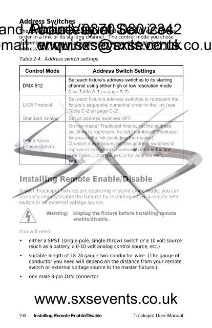
Address Switchesnd The Audio-Visual address Phone: courtesy switch settings 0870 determine ofeither Services 080 the fixture’s 2342numericalorder in a link or its starting channel. The control mode you chosemail: determines how you set the address switches. See Table 2-4 foraddress enquiries@sxsevents.co.ukswitch www.sxsevents.co.uksettings.Table 2-4. Address switch settingsControl ModeDMX 512LWR ProtocolStandard AnalogStand Alone(Master/Slave)Address Switch SettingsSet each fixture’s address switches to its startingchannel using either high or low resolution mode(see Table A-1 on page A-2).Set each fixture’s address switches to represent thefixture’s sequential numerical order in the link (seeTable C-2 on page C-2).Set all address switches OFF.On the master <strong>Trackspot</strong> fixture, set the addressswitches to represent the total number of <strong>Trackspot</strong>fixtures in the link (including the master).On each slave fixture, set the address switches torepresent the fixture’s numerical order in the link.See Table C-2 on page C-2 for address switchsettings.Installing Remote Enable/DisableIf your <strong>Trackspot</strong> fixtures are operating in stand alone mode, you canremotely enable/disable the fixtures by installing either a remote SPSTswitch or an external voltage source.Warning:Unplug the fixture before installing remoteenable/disable.You will need:• either a SPST (single-pole, single-throw) switch or a 10 volt source(such as a battery, a 0-10 volt analog control source, etc.)• suitable length of 18-24 gauge two-conductor wire (The gauge ofconductor you need will depend on the distance from your remoteswitch or external voltage source to the master fixture.)• one male 8-pin DIN connectorwww.sxsevents.co.uk2-6 Installing Remote Enable/Disable <strong>Trackspot</strong> User <strong>Manual</strong>
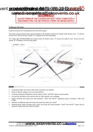
DATA INDATA OUTVOLTAGE SELECTWARNING: CHANGE VOLTAGE SELECT ONLY WI TH POWER REMOVED.CAU TION : HOT R EMOVE POW ER BEFORE RELAMPINGUSER MANUAL.TI LTMSP EEDGOB OANALOG IN0-10VANALOGGND7SHUTTERCOLORPANDIM24 VDCOUT(UNREG.)ADDRESS010203040506070809101112SPECIAL ANALOGINPUTGND4 2531687FOR FUTHER INFORMATIONCONSULT USERS MANUAL2209 WEST BRAKER LANE, AUSTIN, TEXAS U.S.A.SWITCHESONnone121,231,32,31,2,341,42,41,2,4ADDRESS131415161718192021222324FOR FURTHER INFORMATIONPLEASE CONSULT USER MANUALPERSONALI TYFI XT URE MODE SWI TCHES 1-2SET-UPLAMP SAVESWITCHESON3,41,3,42,3,41,2,3,451,52,51,2,53,51,3,52,3,51,2,3,5SWITCHESON21,2CONTROL MODE SWITCHES 3-8LIGHTWAVE CONTROL NONEDMX 1-2565DMX 257-5124ANALOG4,5AUDIO (SLAVE)386TI LT INVERT7FOR FURTHER INFORMATIONPLEASE CONSULT USER MANUALSPST Switchnd Audio-Visual Phone: courtesy Note: Connect only 0870 the master of fixture Services 080 to the SPST 2342 switch.To install an SPST switch:mail: enquiries@sxsevents.co.ukwww.sxsevents.co.uk1. Unplug the fixture.2. Locate the female Analog In connector on the rear panel of themaster <strong>Trackspot</strong> fixture (see Figure 2-2).4 2 51 8 36 7140200120240WARNING: NOT FOR RESI DENTIAL USE. TO REDUCE THE RISK OFFI RE OR E LECTRI C SHOCK, DO NOT EXPOSE TO RAIN OR MOISTURE,NO USERSERVICEABLE PARTS INSIDE. REFER SERVICI NG TOQUALIFI ED SERVI CE PERSONNEL. FOR SAFE OPERATION CONSULT100220FUSEFAN®trackspotENABLELI GHTWAVE RESEARCHADDRESSPERSONALITYAUDIOMIC2NORMAL RUNSELF TESTNONE1OFFONMODELSERIALFACTORY SET VACWATTSHZDATEQC1 4 2 6853AUDIO (MASTER)PAN INVERTremote SPST switchAnalog In ConnectorFigure 2-2. Connecting a remote enable/disable switch tothe master fixture3. Connect DIN pin 1 and pin 5 together (see Figure 2-2). You canconnect these pins either at the fixture or in the male 8-pin DINconnector.4. Connect DIN pin 1 and pin 3 to the SPST switch (see Figure 2-2).When correctly connected to the SPST switch, the fixtures will beenabled when the circuit is closed and disabled when the circuit isopen.External Voltage SourceNote:Connect only the master fixture to the external voltagesource.To install an external voltage source:1. Unplug the fixture.2. Locate the Analog In female connector on the rear panel of themaster <strong>Trackspot</strong> fixture (see Figure 2-2).www.sxsevents.co.uk3. Connect analog DIN pin 1 and pin 5 together (see Figure 2-2). Youcan connect these pins either at the fixture end or in the male 8-pinDIN connector.<strong>Trackspot</strong> User <strong>Manual</strong> Installing Remote Enable/Disable 2-7