Klark-Teknik DN9848.pdf - SXS Events
Klark-Teknik DN9848.pdf - SXS Events
Klark-Teknik DN9848.pdf - SXS Events

Create successful ePaper yourself
Turn your PDF publications into a flip-book with our unique Google optimized e-Paper software.
THE OUTPUT CHANNELS<br />
ent production courtesy Phone: of and Audio-Visual 0870 080 2342 Services<br />
www.sxsevents.co.uk<br />
email: enquiries@sxsevents.co.uk<br />
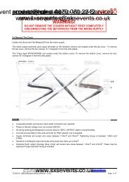
Input block diagram:<br />
Inputs<br />
Routing<br />
Delay<br />
Phase<br />
x2<br />
Low<br />
Pass<br />
High<br />
Pass<br />
PEQ 1/<br />
LEQ<br />
Clip<br />
Output<br />
Metering<br />
Output<br />
PEQ 2 PEQ 3 PEQ 4 PEQ 5<br />
PEQ 6/<br />
HEQ<br />
Gain/<br />
Invert<br />
Limiter<br />
Mute<br />
Output<br />
Metering<br />
Feed<br />
10<br />
The output channels are slightly more complex than the input channels insomuch as they are<br />
responsible for the signal routing as well as for further signal processing. At the input of each Output<br />
channel is a routing block capable of connecting that output to any of the available combinations of the<br />
four Input channels. This provides the user with the flexibility required to construct any crossover type<br />
up to 8-way. This is followed by a Delay, two independent phase correction stages, the crossover low<br />
and high-pass filters, six further stages of fully parametric equalisation and a limiter. All key stages are<br />
monitored by the output meters and each channel can be muted by pressing the output level control pot.<br />
OUTPUT LEVELCONTROLS<br />
Each of the eight output channels is fitted with a level control potentiometer that also incorporates a<br />
push switch. Pressing the potentiometer knob mutes the channel and causes the red status LED ring<br />
around the control to light.<br />
MENU SELECTION KEYS<br />
Each of the eight outputs is fitted with a momentary action output channel selection button. These have<br />
integral amber status LEDs that light when the channel is selected.<br />
OUTPUT BARGRAPH METERS<br />
Each of the eight outputs has an 11-segment bargraph display that shows the true output signal level at<br />
all times. The red segment at the top of the meter illuminates when the clip threshold has been reached.<br />
HOME (SETUP) KEY<br />
The function of this key depends on the context in which it is used. One of its main functions is to exit<br />
the current operation and return to the first page of the menu structure. Pressing and holding this key for<br />
more than one second calls up the Setup menu.<br />
PC PORTS<br />
An 8-pin mini-DIN connector is provided on the front panel for connection to the RS-232 serial port of a<br />
PC or other remote control device conforming to the RS-232 protocol. A standard XLR is provided on<br />
the rear panel for connection to RS-485 for remote control.<br />
POWER<br />
The power switch activates the unit and the <strong>Klark</strong> <strong>Teknik</strong> logo on the front panel will illuminate. The<br />
circuitry is designed so that no audio transients or thumps are generated when powering up or down. It<br />
is also possible to program a 'ramp up time' for the audio output.<br />
www.sxsevents.co.uk