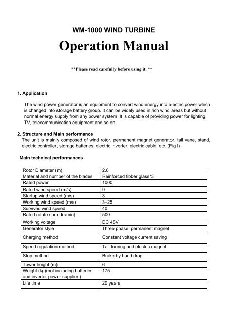
WM-1000 WIND TURBINE Operation Manual - Carpat Energy
WM-1000 WIND TURBINE Operation Manual - Carpat Energy
WM-1000 WIND TURBINE Operation Manual - Carpat Energy

Create successful ePaper yourself
Turn your PDF publications into a flip-book with our unique Google optimized e-Paper software.
<strong>WM</strong>-<strong>1000</strong> <strong>WIND</strong> <strong>TURBINE</strong><br />
<strong>Operation</strong> <strong>Manual</strong><br />
**Please read carefully before using it. **<br />
1. Application<br />
The wind power generator is an equipment to convert wind energy into electric power which<br />
is changed into storage battery group. It can be widely used in rich wind areas but without<br />
normal energy supply from any power system .It is capable of providing power for lighting,<br />
TV, telecommunication equipment and so on.<br />
2. Structure and Main performance<br />
The unit is mainly composed of wind rotor, permanent magnet generator, tail vane, stand,<br />
electric controller, storage batteries, electric inverter, electric cable, etc. (Fig1)<br />
Main technical performances<br />
Rotor Diameter (m) 2.8<br />
Material and number of the blades Reinforced fibber glass*3<br />
Rated power <strong>1000</strong><br />
Rated wind speed (m/s) 9<br />
Startup wind speed (m/s) 3<br />
Working wind speed (m/s) 3–25<br />
Survived wind speed 40<br />
Rated rotate speed(r/min) 500<br />
Working voltage<br />
DC 48V<br />
Generator style<br />
Three phase, permanent magnet<br />
Charging method<br />
Speed regulation method<br />
Stop method<br />
Constant voltage current saving<br />
Tail turning and electric magnet<br />
Brake by hand drag<br />
Tower height (m) 6<br />
Weight (kg)(not including batteries 175<br />
and inverter power supplier )<br />
Life time<br />
20 years
3. Preparation<br />
3.1 Filling in electrolyte and do initial charge according to technical regulations.<br />
3.2 Unpack and check the machine parts.<br />
3.3 Choose an open and flat place with no barriers around for wind turbine installation.<br />
To avoid circuit power loses, should make the distance between wind turbine and batteries<br />
as short as possible, usually it should be less than 30m.<br />
3.4 Foundation installation<br />
3.41 Dig a cubic hole in the center of the ground with size of 40X40X40cm. Then dig four<br />
triangular pits at the place of A, B, C, and D, which are symmetrically 4 meters from the<br />
central hole in four directions. The diagonals of A-C and B-D vertically intersect at the<br />
center of square hole. The depth and side length are 70cm. (Fig 2)<br />
3.42 Fix the 4 foundation bolts onto the base plate. Screw on the M16 nuts respectively until the<br />
top of bolt is 15mm out of nut. Let the axe of pin dead against BD or AC. The Base plate<br />
should be 4-5cm above the ground. Then adjust the base plate in level and concrete the<br />
cubic hole. The mixture ratio of concrete is cement: sand: cobble= 1:2:3.<br />
3.43 Hold the top of chain, and put the anchor horizontally into the base of pit following the<br />
outboard side. Lay crushed stone (about 2~5kg) into the pits, then concrete them; Lay<br />
crushed stone into the pits and concretes them again. Repeat until cram the triangular pit.<br />
Finally draw the guy wires toward the ground center with an angle of 60-degree from the<br />
ground. Hold the chain,concrete the pit until the middle part of the top link, the other half is<br />
out of the concrete. (Fig 3)<br />
3.44 The protection period of the concrete basement is 100 hours. During this period, don’t<br />
install the wind turbines.<br />
4. Installation procedure<br />
4.1 Select a sunshine day without wind (wind speed smaller than 3m/s)<br />
4.2 Adjust the Base plate in level, then put the washer onto the foundation bolt, fasten the nuts.<br />
Fit together the upper, middle, lower mast. Fall the mast on the “A” pit. Link the mast bottom<br />
to the base plate with Φ16 pin, then put on the washer and connects them with ringent pin.<br />
4.3 Draw the guy wires in four directions. Bend the tip of the steel wire to a ferrule, the length of<br />
which is about 20cm. Then fasten it with two wire-clamps. Put the rings for guy wires onto<br />
the top of mast. Then close upon the four ferrules and thrill through the annulus of the ring<br />
respectively. Finally shove them to the outshoot of mast.<br />
4.4 Put the heart ringer for steel wire across the “o” loop of turnbuckle, and then rip the steel<br />
wire into the heart ringer. Bend for a ferrule; no less than 30cm long, fasten with wire-clamps.<br />
Hook the turnbuckles of A, B and D pits to the chain of anchor. Draw back the mast, and<br />
then hook the turnbuckle and anchor chain. Adjust the length of steel wire through<br />
turnbuckles to plumb the mast. Install the stay bar to the lower mast,fix up it with M12 bolts.<br />
Untie “U” shape screw between anchor and turnbuckle of pit C. Connect the steel wire of C
pit and the top of stay bar and fasten it. Then adjust until the steel wire between stay bar and<br />
mast in strain state.<br />
4.5 Put a 1m bracket into pit A. Loose the “U” shape screw buckle in pit B and pit D (About<br />
5cm length). Untie the link of the “U” shape screw and the ground anchor chain in pit C.<br />
Fall down the mast slowly; support the steel wire pothook with20cm height stow-wood.<br />
4.6 Insert the cable through the bottom to the top of the mast with a steel wire(¢2~3mm) and<br />
extend out about 20 to 50cm. Connect the 3 thrum of the cable (which derivative from the<br />
slip ring) with the terminal block.<br />
Connect the 3 thrum of the cable which derivative from the slip ring with the terminal block.<br />
4.7 Install the generator onto the mast top through the sleeve. Fasten the screw.<br />
4.8 Assemble the tail rod to the rotating body, setting the M10 holes correctly, insert the spring<br />
washer; screw the four M10X25 inner six angle nuts tightly. (FIG5)<br />
4.9 There are two holes can be chosen on the trough shape clamp of the tail rod and two holes<br />
distributing on the two sides of the tail vane tie-in’s axes, whose diameter is 11. Insert the<br />
tie-in of tail vane into the trough shape clamp of the tail rod, insert M10X60 bolt into the ø11<br />
holes correctly, put on washer10, spring washer 10 and M10 self-locked nuts, Adjust the<br />
tail rod angle against the level plane according to the local wind resources and electricity<br />
consumptions (it can be adjusted to four angles). Decrease the angle can increase the<br />
rotating speed of the rotor. Then insert the screw shaft into ø11, screw the adjusting bolt<br />
and nut (M10). After adjusting, tighten the two self-locked nuts. (See fig.6).<br />
4.10 Before leaving the factory, every rotor had been assembled and passed the balance<br />
adjustment. For easy transport, the rotor had been disassembled. When reassembling the<br />
rotor, please check the marks on the parts, so as to make them return to the former<br />
positions, then fit the M10×80 screws, washers, M10 self-locked nuts one by one. Tighten<br />
the nuts with a small force first, then measuring the distances between the centre point to<br />
the tip end of blades a, b, c, the distance among the three sizes should less than 5mm,<br />
then tighten the nuts firmly. The tighten torque should be 40 – 45 N.m (see fig.7).<br />
4.11 Assemble the blade-rotor on the axes of generator, put on the flat washer, spring washer<br />
one by one, and then screw the self-locked nut tightly。<br />
4.12 Assemble the nose cone to the rotor hub with M6 screws, spring washers and flat<br />
washers.<br />
4.13 Draw backs the mast through chain jack; connect the screw buckle of pit C to the anchor.<br />
Adjust the length of the screw buckle in four directions. Strain the steel wires to make the<br />
mast in its vertical position. Strain the steel wire until it can rebound lightly when gives a<br />
transverse force.<br />
4.14 Check the wire block, screw buckle and all connecting point. Make sure it is safety. Then<br />
wrap and blocked them with galvanized wire. Put anticorrosive grease on wire block,<br />
screw buckle and all links where necessary.
4.15 The two connectors of battery is anode and cathode, connect them in series to be a group.<br />
Choose the lead whose sectional area is 6 square millimeters as connect wire. The wire of<br />
anode is marked by red color; and cathode is marked by black (or yellow, or blue). All<br />
connect point should fix up by splicing fitting to ensure electric conduction is good. In<br />
order to prevent acid corruptness of the splicing fitting and connecting pole, spread a layer<br />
of protection grease on them..<br />
4.16 Connect the red wire of anode of the batteries to the anode pole of the controller or<br />
control-Inverter; then, connect the black wire of cathode of the batteries to the cathode<br />
pole the controller or control-Inverter. Connectors must be tightened firmly and ensure<br />
good electric conduction.<br />
4.17 Connect the 3 output wires of the generator to the 3-connector poles of the controller or<br />
control-inverter respectively. During the process of connecting, the “open & close” switch<br />
on the controller or control-inverter box should keep on “close” position..<br />
4.18 According to different requirements, there are two kinds of output: DC and AC. Please<br />
connect according to marks on the socket. Take care for safe operation when the output is<br />
AC220V.<br />
5. Application notice<br />
5.1 Application principles<br />
5.1.1 Please read the specification carefully before using. Do not install or uninstall in windy<br />
day.<br />
5.1.2 The off-grid wind turbine charges the batteries through controller or control-inverter. When<br />
there is no wind, it consumes the electricity from the battery group. Therefore, after<br />
discharging, the batteries should be recharged timely, especially for lead-acid batteries. If<br />
the batteries cannot be recharged timely after over discharging, the working life of the<br />
batteries will be reduced. So, the users should regulate the consuming of electricity<br />
according to local wind condition and the output of the wind generator.<br />
5.1.3 After passing full wave bridge rectification, the 3-phase AC electricity generated by wind<br />
generator output DC voltage, and then charge the battery. The voltage of the battery<br />
group should be equal to the DC voltage of the wind generator (after rectification), so the<br />
enginery can exert its full efficiency. The input DC voltage of matched inverter should be<br />
equal to the working voltage of wind turbine.<br />
5.1.4 The input DC voltage of the matched inverter should be equal with working voltage of the<br />
wind generator (after rectification).<br />
5.2 Safety regulations<br />
5.2.1 Forbidden the wind generator running without any load, or running at a very high rotating<br />
speed continually.<br />
5.2.2 Checking the tower condition regularly, if there are any loosen phenomenon, it should be<br />
tighten immediately, so as to prevent the falling down of the wind turbine.<br />
5.2.3 When running speed of the rotor is higher, people are forbidden to stay under the wind<br />
turbine.
5.2.4 When wind speed is more than 24 m/s, the wind turbine should be stopped artificially.<br />
5.2.5 When vibration or strange noise is found during working, please stop the wind turbine and<br />
check the reasons.<br />
5.2.6 The power supply line of the wind generator should be arranged independently, it can not<br />
be mixed used with other power supply lines. DC power supply is more safe and<br />
economic for illuminators; for home electric appliances, the AC power supply line (from<br />
inverter) should be used; it is suggested that the connector of the refrigerator should insert<br />
in the special plug seat with time lapse function<br />
5.2.7. When connect the electric line of the wind generating system, the battery lines must be<br />
first connected to the controller & inverter box, then connect the three lines of the<br />
generator to the controller. When disconnect the electric line of the wind generating<br />
system, the three generator lines must be first disconnected from the controller, then<br />
disconnect the two lines of the battery group from the controller & inverter box.<br />
5.2.8 The “open & close” switch on the controller & inverter box should keep at “open” position<br />
in normal conditions. Only when the batteries have been full charged or for protect the<br />
system against storm wind, the switch can be put on “close” position. It is not allowed to<br />
move the switch when wind is stronger and rotor is rotating at high speed, turning the<br />
switch to “close” position when rotor is rotating slowly.<br />
5.2.9. The batteries should be set on a place where far from fare resource and heat resource,<br />
the gas generated from charging and discharging process should be easy go out of the<br />
room.<br />
5.3.Keep the rotor balance, eliminate vibration<br />
When the blades lost balance caused by outside damage and create strong vibration, the<br />
wind generator must be stopped and checked, until the trouble is eliminated. The attached<br />
special tools should be used for disassembling the rotor, remove the nut and washer from<br />
the axes end of generator first, screw the special sleeve onto the hub firmly, then drive the<br />
M16 × 30 screw into the sleeve, so as to remove the rotor from the shaft of the<br />
generator(see fig.8). After repairing, the un-balance torque should less than 0.02N.m.<br />
6. The maintenance of the wind generator<br />
The products are divided into two kinds: common product and high quality product (no<br />
maintenance), the common product need following maintenances regularly.<br />
6.1. Checking, cleaning and lubricating all rotating parts one time per year.<br />
6.2 Before rain season, cleaning outside and paint antirust grease on the surface of all fixed<br />
connecting parts once a year.<br />
6.3 Lubricating and maintenance bearing of generator one time per operating year.
6.4. Cleaning, rust removing and painting all exposed parts one time per every two years.<br />
The maintenance of high quality product (AA)<br />
a. Exposed parts are made by stainless steel or have passed special long time effective<br />
rust-protection treatment, so the outside of those parts don’t need maintenance.<br />
b. The generator has adopted high grade bearings and high grade lithium grease, the bearings<br />
need to be checked after operating for 5 years, if it is necessary, add some grease to the<br />
bearings.<br />
7. Elimination of breakdown<br />
The wind generator is designed and manufactured according to trouble- free and nonmaintenance<br />
principle, if the installation and operation are correct, the breakdown will not<br />
appear in normal conditions. In case of breakdown has happened, please consult following<br />
table.<br />
Breakdown reason Eliminating method<br />
Wind generator 1. Pull rope of steel wire is loose. 1. Tighten the steel wire rope appropriate.<br />
vibrating strongly 2. Fixed bolts of blades are loose.<br />
3. Blade is defective caused by<br />
outside force.<br />
4. Ices over on the surface of blades,<br />
2. Tighten the loose parts.<br />
3. Replace a new one and adjust the rotor<br />
to balance state again.<br />
4. Eliminating the attached ices.<br />
cause unbalance.<br />
Direction regulating 1. There is too much greasy filth in 1. Clearing away the dirty filth, and make a<br />
is ineffective<br />
the rotating body.<br />
lubricating maintenance.<br />
Rotating part is deformed by 2. Recover and correct the deformation.<br />
outside force.<br />
2. The clearance between vertical<br />
shaft and sleeve is too small, or<br />
there is no movable axial<br />
clearance.<br />
unusual noise 1. Fixed parts is loose<br />
1. Put the wind turbine down to the ground,<br />
2. Generator bearing is damaged check every fixed part, and take<br />
3. Wind rotor is rubbing with other<br />
part.<br />
measures.<br />
2. Replace the damaged bearing.<br />
3. Checking and eliminating the trouble.<br />
The rotating speed<br />
of the wind rotor is<br />
reduced obviously<br />
The output voltage<br />
of the generator is<br />
low<br />
1. Blade pitch control is ineffective.<br />
2. Stator winding is short –circuit or<br />
output circuit is short pass.<br />
3. Break disk is rubbing.<br />
4. Switch is set at “close” position:<br />
1. The rotating speed of the<br />
generator is low.<br />
2. Permanent magnet rotor has lost<br />
1. Checking and eliminating the trouble,<br />
then making lubrication and<br />
maintenance.<br />
2. Find out short circuit position, split the<br />
lines and isolate them..<br />
3. Readjust the break gap.<br />
4. Set switch at “open” position.<br />
1. Finding out the reason, restoring to<br />
normal rotating speed.<br />
2. Charging magnet, or change the rotor of
There are not<br />
output electric<br />
current in AC circuit<br />
of the Generator<br />
its magnet.<br />
3. The conductivity of connect<br />
point between slip ring and output<br />
circuit is weak.<br />
4. There is short circuit in rectifier.<br />
5. Circuit line of low voltage<br />
electricity transmit is too long, or<br />
the diameter of wire is too thin.<br />
1. There are circuit break in AC lines<br />
of the generator, or the fuse is fused.<br />
2. There are circuit break in output<br />
line.<br />
3. Stator winding is burnt, circuit is<br />
broken.<br />
generator.<br />
3. Cleaning slip ring and contact point, so<br />
as to reduce resistance.<br />
4. Replace.<br />
5. Shortening the circuit line or increase<br />
the diameter of the wires, so as to<br />
reduce circuit electricity loss.<br />
1. Find out the reason, and connect the<br />
wires.<br />
2. Find out the break point, then connect<br />
the wires.<br />
3. Disassemble, then repair and recover it<br />
AC output is in<br />
normal condition,<br />
but there is not DC<br />
output current<br />
Output capacity of<br />
the batteries is<br />
insufficient<br />
1. DC fuse is fused.<br />
2. Output circuit is broken.<br />
1. Output voltage of the generator is<br />
too low, or electricity is generated<br />
at all.<br />
2. The connector of the battery is<br />
corroded by acid, conductivity is<br />
weak.<br />
3. Battery is failure<br />
1. Replace.<br />
2. Find out the break point and connect the<br />
wires.<br />
1. Checking and eliminating the<br />
trouble.<br />
2. Cleaning the connectors, enable<br />
them have a good contact and<br />
tighten the connectors.<br />
3. Replace the damaged battery
<strong>WM</strong>-1KW <strong>WIND</strong> <strong>TURBINE</strong> SYSTEM
<strong>WM</strong>-1KW <strong>WIND</strong> <strong>TURBINE</strong> WIRING DRAWING