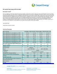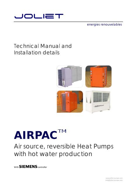
Airpac technical and installation manual EN - Carpat Energy
Airpac technical and installation manual EN - Carpat Energy
Airpac technical and installation manual EN - Carpat Energy

Create successful ePaper yourself
Turn your PDF publications into a flip-book with our unique Google optimized e-Paper software.
LCD DisplayOperation of RWR470.10 is fully driven by buttons <strong>and</strong> menus.Operating buttonsButton Name UseIn Menu /parameter setting mode, press it to return to the previous menulevel, or to reject the value enteredPress down it for more than 2 seconds <strong>and</strong> release it to enter the MenumodeIn Menu/parameter setting mode, press it to confirm the selected menulevel, or the value enteredPress it to acknowledge/reset warnings <strong>and</strong> alarmsPress it for 2 seconds to activate the System Mode in stop modeOr, press it to select the menu level, or to increase the value inMenu/parameter setting modePress it to select the menu level, or to decrease the value inMenu/parameter setting modeLegend for menusIcon Meaning FunctionQuery/viewWarningAlarmParametersActual values of all temperatureExistence of warning, <strong>and</strong> the latest 10 warningsExistence of alarm <strong>and</strong> the latest 20 alarmsSet parameters <strong>and</strong> values (see also Menu Tree)www.joliet‐europe.cominfo@joliet‐europe.com
The unit of compressor <strong>and</strong> pump running time is 100 hours.As for how to access the Query/Warning/Alarm/Parameter menus above, see also < Accessing the Menus>Parameters listed under themenu vary with the password privileged user.Before accessing the Parameter menu, select the user group (“NO” “EU” or “ID”) first <strong>and</strong> input the correspondingpassword that is required for the service men <strong>and</strong> factory users.See also Legend for system Mode <strong>and</strong> statusOn the right lower side, nine icons are used to indicate system modes <strong>and</strong> status.Icon Meaning Icon MeaningPower on/OffCoolingHeatingHot water(The icon is displayed inhouse)compressorDefrostHouse (All devices within this icon are called indoor devices.)When the device is activated, the corresponding icon will be lit.Legend for devicesOn the right middle area, the icons are used to indicate the work status of the devices.Icon Meaning Status <strong>and</strong> IndicationCompressorFlow switchIndoor pumpcondenser fanOn solid: RunningBlinking : Alarms related to compressorBlinking: flow switch alarmOn solid: runningBlinking: alarms detectedFor any warning/alarm detected, the corresponding device icon <strong>and</strong> the / icon will blink continuously untilthe alarm is acknowledged or resetwww.joliet‐europe.cominfo@joliet‐europe.com
Menu TreeBy default, end users can access all parameters in ST group.Legend for parameter groupsCode Indication Code IndicationCM Compressor settings ST Set pointsCN Condenser settings UI User interfaceEV Evaporator settings AL Alarm settingsSF Special functions DF Defrost settingsAccess RightsThree groups of users with different privilege levels are described below.PrivilegeLevelIDEUNOUserFactoryUserServiceMenEndUserMain ActivitiesSpecial• Password required• Configure <strong>and</strong> commissionapplications by setting/adjustingparameter values• Password required• Configure <strong>and</strong> commissionapplications by setting/adjustingparameter values• No password is required• Adjust limited values of parameters(by default , can only adjust valuesof parameters in the “ST” group)All• View information<strong>and</strong> status• Acknowledgewarnings <strong>and</strong>alarms• Heating /Coolingchangeoverwww.joliet‐europe.cominfo@joliet‐europe.com
Wiring ExamplesConnection TerminalsBrief descriptions of the inputs <strong>and</strong> the outputs are summarized as follows.Terminal AssignmentsTerminal AssignmentsG Power supply AC/DC 24 V Q13 Supply 1 (AC 24 V …230 V)G0 Power supply ground Q14 Compressor1PE Safety ground Q24 Compressor2Q34 Indoor water pumpX1 Inlet water temperature of indoor side Q44 Condenser fanX2 Outlet water temperature of indoor side Q54 4-way valveX3 Atmospheric temperature of outdoor Q64 BoilerX4 Hot water temperatureX5 Condenser temperature Q23 Supply 2 (AC 24 V …230 V)X6 evaporating temperature Q74 3 way valveGND Common reference point for analogue input Q84 Alarm+5 V DC 5 V power output for active sensor Y1 Condenser fan 2+24 V DC 24 V power output for active sensor GND Common reference pointD1Water flow switchY2Analogue output 2, 0...10 VD2 Low pressure switch A+ A+ connector for RS485D3 high pressure switch B- B- connector for RS485D4 Air condition switch GND Optional for RS485 communicationD5 Hot water switch RJ45Service interface for parametersuploading <strong>and</strong> downloadingM Common reference point for digital inputwww.joliet‐europe.cominfo@joliet‐europe.com
Wiring with Power SupplyRWR470.10 is supplied with 24 VAC ± 20 % or 24 VDC ± 10 % via plug‐in terminals G <strong>and</strong> G0Wiring with Digital InputsRWR470.10 offers five digital inputs for connecting safety devices, alarms, device status, <strong>and</strong> remote switches.These digital inputs are voltage free.The following figure represents an example of wiring the digital inputWiring with Passive Temperature SensorsBefore wiring with passive sensor, pay attention to the following:• Terminals X1…X6 can be wired with NTC 10K sensor.www.joliet‐europe.cominfo@joliet‐europe.com
General Device SettingsModes of OperationThe current RWR470.10 controller consists of three kinds of operation modes:ModeFunction1 Normal working mode Display all running devices <strong>and</strong> measured values2 Menu mode* View configured analogue inputs, warning <strong>and</strong> alarmlogsSet/adjust parameter values <strong>and</strong> also user privilege toparameters3 Stop mode** Normally shut‐down status (all units stop running.)*To enter menu mode, see also .• In normal working mode, the back light will be timed out after 30seconds without any operation.Accessing the MenusDisplay.+-ProceduresIn Stop mode, press the buttonfor 2 seconds <strong>and</strong> release it to enter theMenu mode.By default, the Query icon is blinking,waiting for further instructions.To view the latest 10 warnings generated:• Navigate to the menu by pressing or , <strong>and</strong> then press to confirm <strong>and</strong> proceed.To view the latest 20 alarms generated:• Navigate to the menu by pressing or , <strong>and</strong> then press to confirm <strong>and</strong> proceed.To set parameter values:• Navigate to the menu by pressing or , <strong>and</strong> then press to confirm <strong>and</strong> proceed. Contents under this menu may vary with the privilege rightof the user.− For end users, select “NO,” <strong>and</strong> press to proceed.− For service men <strong>and</strong> factory users, select “EU” or ”ID” <strong>and</strong> press toinput the password.www.joliet‐europe.cominfo@joliet‐europe.com
Defrost SettingsDF02DescriptionsFan defrost- 0=Disabled- 1=Enabled (when outdoor temperature ≥DF02)Set point of outdoor temperature when fan defrost(When outdoor temperature ≥the set point <strong>and</strong> DF01=1, adopt f<strong>and</strong>efrost)Min. Max. Unit Res Privilege1 0 1 - 1 15.0 1.0 10.0 ºC 0.1 1DF03 Set point of outdoor temperature 10.0 3.0 20.0 ºC 0.1 1DF04 Set point of defrost temperature difference (outdoor temperature-coiltemperature)10 5 20 ºC 0.1 1DF05 Running time(compressor continuous running time when coil temperature 5 1 60 Min 1 1≤DF04)DF06 Minimum defrost interval 30 15 60 Min 1 1DF07 Compressor transfers delay from OFF to ON before defrost, fromheating to cooling10 6 180 Sec 1 1DF08 Compressor transfers delay from OFF to ON after defrost, fromheating to cooling10 6 180 Sec 1 1DF09 Coil temperature when quite from defrost 5 1 20 ºC 0.1 1DF10 Defrost time ( from compressor ON) 300 1 1000 Sec 1 1DF11 Minimum air conditioner’s keep temperature 15 10 40 ºC 0.1 1User InterfaceParameterDF01DefaultParameterDescriptions De‐fault Min. Max. Unit Res. PrivilegeUI01 Password for service user 1234 0 9999 - 1 1UI02 Password for factory user 4321 0 9999 - 1 2Alarm SettingsDescriptionsParameterDefaultMin. Max. Unit Res. PrivilegeAL01 Protecting Set point for low outlet water temperature 3 1 10 ºC 1 1AL02 B<strong>and</strong> of low outlet water temperature 2 1 10 ºC 1 1AL03 Protecting Set point for high outlet water temperature 55 1 100 ºC 1 1
AL04 B<strong>and</strong> of high outlet water temperature 15 1 20 ºC 1 1AL05 Feedback Delay for water current switch 10 1 100 Sec 1 1AL06AL07total alarm number within 24 hours in low pressure(Over this limit, alarm “AL18” will be reported.)total alarm number within 24 hours in high pressure(Over this limit, alarm “AL19” will be reported.)4 1 10 - 1 16 1 10 - 1 1AL08 Protecting Set point for low evaporator temperature -2 -10 10 ºC 0.1 1AL09Time rang during which low pressure will be ignored whencompressor ON.300 0 1000 Sec. 10 1Heating compensation curve(SF04=1)The control temperature for heating mode has two methods: fix <strong>and</strong> changeable temperature. The fixtemperature is a fixed value <strong>and</strong> directly set by the end user from the set area. The changeabletemperature is determined by values of ST05, ST06 <strong>and</strong> the tested outdoor temperature by thecontroller.This function is selected by SF04, when SF04=0, it is fix temperature; when SF04=1, it is changeabletemperature.The following curve will show the detail of changeable mode when ST05=20℃RT/ST temperature℃1009080706050403020 17151311975320100-10-20-30℃Outside temperatureSet the heating compensation coefficient ST06 is 5,When outdoor temperature is 5℃, the control temperature is 28℃;When outdoor temperature is -10℃, the control temperature is 35℃;When outdoor temperature is –20℃, the control temperature is 40℃;With the drop of the outdoor temperature, the control temperature become higher <strong>and</strong> higher to meetthe large heating requirement.With the increase of the outdoor temperature, the control temperature become lower <strong>and</strong> lower, so thatthe heat pump works under low pressure to keep low energy consumption.
DimensionsLSQ06R1/Cwater outletwater inletLSQ08R1/C, LSQ10R1/C, LSQ08R1/CR, LSQ10R1/CRHeater wateroutletHeater waterinletA/C wateroutletA/C waterinlet
LSQ10R1, LSQ10R1/RHeater wateroutletHeater waterinletA/C wateroutletA/C waterinletLSQ13R1, LSQ15R1, LSQ13R2, LSQ15R2, LSQ13R1 /R, LSQ15R1/R, LSQ13R2/R, LSQ15R2/RHeater wateroutletHeater waterinletA/C wateroutletA/C waterinlet
LSQ20R2, LSQ20R2/RHeater wateroutletHeater waterinletA/C wateroutletA/C waterinletLSQ25R2, LSQ31R2, LSQ25R2/R, LSQ31R2/RHeater wateroutletHeater waterinletA/C wateroutletA/C waterinlet
LSQ66R2Water outletWater inletHeater wateroutletHeater waterinletA/C wateroutletA/C waterinlet
St<strong>and</strong>ardsEC Directives:73/23/EEC89/336/EECHousehold <strong>and</strong> similar electrical appliances. Electromagnetic fieldsEMC Low voltage directive 2006/95ECBS <strong>EN</strong> 60335‐1‐:2002+A1 : 2004+A11 : 2004+A12 : 2006+A2 : 2006BS <strong>EN</strong> 60335‐2‐40:A1 : 2006+A11 : 2004+A12 : 2005Specification for safety of household <strong>and</strong> similar electrical appliances.EMC Directive 2004/108/EC<strong>EN</strong>55014‐1 : 2000+A1 :2001+A2 : 2002 Power disturbances test & Terminal voltage test<strong>EN</strong>55014‐2 : 1997+A1 : 2002<strong>EN</strong>55014‐2 (<strong>EN</strong>61000‐4‐2), ESD test<strong>EN</strong>55014‐2 (<strong>EN</strong>61000‐4‐3), Radio frequency electromagnetic fields test<strong>EN</strong>55014‐2 (<strong>EN</strong>61000‐4‐4), Fast transients test<strong>EN</strong>55014‐2 (<strong>EN</strong>61000‐4‐5), Surges test<strong>EN</strong>55014‐2 (<strong>EN</strong>61000‐4‐6), Injected currents test<strong>EN</strong>55014‐2 (<strong>EN</strong>61000‐4‐11), Voltage dips <strong>and</strong> interruptions test<strong>EN</strong>61000‐3‐2 : 2006 Harmonics test<strong>EN</strong>61000‐3‐3 : 1995+A1 : 2001+A2 : 2005 Voltage fluctuation testContactTel. 00 34 972 505 557 ou 00 34 972 67 77 98Fax. 00 34 972 67 77 96Info@joliet‐europe.comwww.joliet‐europe.comJOLIET (<strong>EN</strong>ERGY) TECHNOLOGY SL Placa Europa 45 17600 Figueres GironaJoliet Technology SL – Reg. B63850549 – CL Balmes 152 – 08008 Barcelona