MODAL ANALYSIS OF THE ROTOR SYSTEM TOMÁŠ JAMRÓZ ...
MODAL ANALYSIS OF THE ROTOR SYSTEM TOMÁŠ JAMRÓZ ...
MODAL ANALYSIS OF THE ROTOR SYSTEM TOMÁŠ JAMRÓZ ...

Create successful ePaper yourself
Turn your PDF publications into a flip-book with our unique Google optimized e-Paper software.
20th SVSFEM ANSYS Users' Group Meeting and Conference 2012<br />
SVSFEM s.r.o<br />
<strong>MODAL</strong> <strong>ANALYSIS</strong> <strong>OF</strong> <strong>THE</strong> <strong>ROTOR</strong> <strong>SYSTEM</strong><br />
<strong>TOMÁŠ</strong> <strong>JAMRÓZ</strong>, KAREL PATOČKA, VLADIMÍR DÁNIEL, <strong>TOMÁŠ</strong> HORÁČEK<br />
Aerospace research and test establishment<br />
Abstract: The article deals with the issue of modelling of fundamental dynamic<br />
calculations in ANSYS Workbench environment. There are shown discrepancies in the<br />
modal analysis calculation of bodies system using an unstructured grid. It is pointed out<br />
correct choice of function for the contact surface. Furthermore, the article highlights the<br />
problem of preload modal analysis. There is shown the influence of the function "Bolt<br />
Pretension" on the results of a modal analysis.<br />
Keywords: modal analysis, rotor, preload<br />
1 Introduction<br />
This article deals with the issue of modelling of fundamental dynamic calculations in the<br />
ANSYS Workbench environment. Under the term basic dynamic characteristics are<br />
understood modal properties such as natural frequencies and eigenmodes of the system.<br />
These basic dynamic characteristics are obtained for rotor system of free turbine<br />
consisting of 13 parts. The reason for the identification of modal parameters is their<br />
subsequent use in the optimization of the main and distributor gear set.<br />
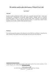
Fig. 1 Construction of rotor system<br />
http://aum.svsfem.cz<br />
1
20th SVSFEM ANSYS Users' Group Meeting and Conference 2012<br />
SVSFEM s.r.o<br />
Modal properties of above mentioned rotor system were solved in the software Ansys<br />
Workbench environment. There was placed emphasis mainly on torsion modes of system<br />
whose dynamic characteristics have the greatest influence on the dynamics of gearing.<br />
Free free modal analysis of the system was calculated, thus excluding boundary<br />
conditions of rotor system. It was also taken into consideration the mounting requirements<br />
and examined the effect of rotor system preload. Preload of the rotor system was<br />
modelled using multi-bodies and contact functions instead of using one bond solid from a<br />
CAD system.<br />
2 Modeling of preload<br />
As mentioned in the introduction, the rotor assembly is preloaded in the axial direction of<br />
the axial force. This preload is given by torque union nut, which fixed the rotor system of<br />
the rotor shaft in the axial direction. Shift of natural frequencies of the rotor system was<br />
investigated with respect to the axial preload.<br />
The task was solved by two successive analysis: static one followed by modal one with<br />
delegated stiffness matrix from the previous calculation. Preload of rotor shaft was solved<br />
with the help of "Bolt Pretension" function which was applied to the in the halfway crosssection<br />
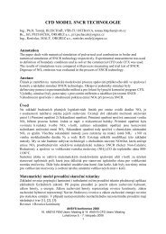
of the shaft between the bearings. The results of structural analysis of rotor<br />
system with preload are shown in Fig.2. The nominal value of normal stress is 48MPa in<br />
the shaft.<br />
Fig. 2 Normal stress in rotor system from preload<br />
The subsequently performed comparison between modal analyses with and without<br />
pretension proved that the preloading has a negligible effect on the natural frequencies<br />
shift with respect to torsion and bending modes. The frequency increase for these modes<br />
was very small. The only natural frequencies of axial modes were markedly affected<br />
(frequency shift was about 30%). Preload had the opposite effect for the modes (the<br />
natural frequencies were reduced).<br />
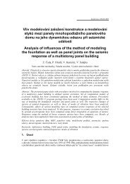
As shown in Fig.3, the substantial decrease of the axial natural frequency values is mainly<br />
caused by the elements in a spot, where the "Bolt Pretension" function was applied to.<br />
The „Bolt Pretension“ function was applied in the form of input load.<br />
http://aum.svsfem.cz<br />
2
20th SVSFEM ANSYS Users' Group Meeting and Conference 2012<br />
SVSFEM s.r.o<br />
Application of preload using either thermal boundary conditions or the “Bolt Pretension”<br />
function in the form of displacement or shifts in contacts could prevent unwanted changes<br />
of natural frequencies in the axial direction at preload modal analysis.<br />
Fig. 3 Axial nature frequency<br />
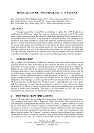
When comparing the eigenmodes of multi-body system with and without preload applied it<br />
was found that the first six rigid modes do not have zero values of natural frequencies.<br />
The frequency values are 155Hz, 155Hz and 285Hz for the rotating modes for the given<br />
rotor set.<br />
Fig. 4 The first torsion nature frequency mode<br />
http://aum.svsfem.cz<br />
3
20th SVSFEM ANSYS Users' Group Meeting and Conference 2012<br />
SVSFEM s.r.o<br />
Tab. 1 Natural frequencies (number 7-10 are the bending modes, 11 is first torsion mode and 12 is<br />
the axial mode)<br />
No. preload Without preload<br />
1 0.55776 4.26E-03<br />
2 0.55809 6.07E-03<br />
3 0.55812 6.28E-03<br />
4 155 154<br />
5 156 155<br />
6 212 212<br />
7 739 739<br />
8 742 742<br />
9 2020 2019<br />
10 2023 2022<br />
11 2850 2853<br />
12 3893 5037<br />
3 Rigid modes issues<br />
As already mentioned in the previous chapter, Ansys Workbench environment in<br />
"standard setting" computes the non-zero rigid modes for the analysis of the system of<br />
bodies connected by contact functions with unstructured mesh.<br />
Another finding was the discrepancy in the values of the natural frequencies for the<br />
system imported into Ansys environment as a single body and for system imported in<br />
Ansys as an assembly and afterwards connected by contact functions in<br />
Ansys/DesignModeler environment. When using the contact function "Bonded-Pure<br />
Penalty" the difference was about 5% w.r.t. single body model. The latter value also<br />
roughly corresponds to the value of the frequency shift of rigid modes. In case of the first<br />
two bending modes and torsion mode the differences were 18% and 12%, respectively.<br />
Fig. 5 The rigid rotation modes<br />
As recommended by representatives of Ansys software, MPC method was used for<br />
contacts. Using such a contact the natural frequencies differences changed from 18% to<br />
5% and from 15% to 2% for the first two bending modes and the first torsion mode,<br />
respectively. The frequency shift was equal about 5% for all other modes. There was also<br />
a significant decrease in the frequency values of the rotating rigid modes - from about<br />
285Hz to about 25Hz.<br />
http://aum.svsfem.cz<br />
4
20th SVSFEM ANSYS Users' Group Meeting and Conference 2012<br />
SVSFEM s.r.o<br />
Tab. 2 Comparison of natural frequencies for contact functions Pure Penalty, Augmented lagrange<br />
and MPC (number 7-10 are the bending modes, 11 is first torsion mode and 12 is the axial mode)<br />
No. One-body<br />
Multi-body system<br />
system<br />
Pure Penalty Augmented<br />
MPC<br />
lagrange<br />
Frequency<br />
[Hz]<br />
Frequency<br />
[Hz]<br />
Shift<br />
[%]<br />
Frequency<br />
[Hz]<br />
Shift<br />
[%]<br />
Frequency<br />
[Hz]<br />
Shift<br />
[%]<br />
1 0 0 0 0<br />
2 0 0 0 0<br />
3 0 0 0 0<br />
4 0 203 203 14<br />
5 0 205 205 24<br />
6 0 285 285 26<br />
7 755 894 18 894 18 795 5<br />
8 756 898 19 898 19 799 6<br />
9 2179 2321 6 2321 6 2284 5<br />
10 2182 2323 6 2323 6 2289 5<br />
11 3480 3850 12 3850 12 3532 1<br />
12 4819 5047 5 5047 5 5044 5<br />
4 Displacement in the gear tooth<br />
In the introduction it was mentioned that the several dynamic variables are needed to<br />
optimize the gearbox. One of the dynamic variables is the average tangential<br />
displacement of the diametral pitch for torsion mode.<br />
The path along the tooth could not be defined by two points for this type of gear because<br />
of helical gearing. Deviation from a straight line is small, but the resulting tangential<br />
displacement values are significantly different.<br />
2,9400<br />
2,9200<br />
2,9000<br />
2,8800<br />
2,8600<br />
2,8400<br />
2,8200<br />
2,8000<br />
2,7800<br />
2,7600<br />
Pure Penalty<br />
2,7400<br />
0,0000 0,0050 0,0100 0,0150 0,0200<br />
Fig. 6 Diagram of tangential displacement along the gear tooth for torsion mode<br />
http://aum.svsfem.cz<br />
5
20th SVSFEM ANSYS Users' Group Meeting and Conference 2012<br />
SVSFEM s.r.o<br />
The curves showing tangential displacement values along the length of the tooth for<br />
different contact function are compared in the Fig. 6. The graph shows that the curve<br />
shape does not change for different contact functions. The curves are only shifted. In<br />
addition, the difference is negligible.<br />
Tab. 3 Comparison of mean value of tangential displacement among contact functions<br />
Body (Contact functions)<br />
Mean value of tangential disp.<br />
[m]<br />
Difference<br />
[%]<br />
One body (no contact function) 2.7925 0.00<br />
Multi-body („Pure Penalty“) 2.9041 3.99<br />
Multi-body („Lagrange“) 2.9041 3.99<br />
Multi-body( „MPC“) 2.8766 3.01<br />
5 Conclusion<br />
In our case the preload has no effect on the natural frequency of the torsion mode but it<br />
can affect the frequency shift of axial modes for particular contact function used. Only if<br />
"Bolt Pretension" in the form of load input is used the frequencies decrease significantly<br />
for all axial modes. This undesirable effect can be avoided by application of preload using<br />
either thermal boundary conditions or the “Bolt Pretension” function in the form of<br />
displacement or shifts in contacts.<br />
In case of modal analysis calculation of multi-body system (where contact function have to<br />
be used), MPC contact function should be used to minimize the shift of natural<br />
frequencies and to bring the natural frequencies of rigid modes near to zero. Then the<br />
frequency deviations are also relatively small compared to one-body system. The nonzero<br />
rigid modes issue does not exist when structured mesh is used.<br />
Acknowledgement<br />
The work was performed with support of EC FP7 project Efficient Systems and Propulsion<br />
for Small Aircraft – ESPOSA. Project number: 284 859<br />
Contact address:<br />
Ing. Tomáš Jamróz<br />
VZLÚ<br />
Beranových 130<br />
19905 Praha – Letňany<br />
jamtoz@vzlu.cz<br />
tel: +420 225115593<br />
- The whole document is written in Arial<br />
- The whole document follows singe lines<br />
- Page margins: left 3 cm, others 2.5 cm<br />
- Image, table and equation numbering is automatic by Seq fields named Image, Tab and Eqv. You<br />
can just copy mentioned fields in this template. Bookmarks and Cross-references should form Field<br />
references.<br />
- symbol of free line<br />
http://aum.svsfem.cz<br />
6