Technical Reference Manual - Support
Technical Reference Manual - Support
Technical Reference Manual - Support

Create successful ePaper yourself
Turn your PDF publications into a flip-book with our unique Google optimized e-Paper software.
<strong>Technical</strong> <strong>Reference</strong><br />
<strong>Manual</strong><br />
MR Series<br />
English<br />
EPSON<br />
403308709<br />
Rev. I
MR Series <strong>Technical</strong> <strong>Reference</strong> <strong>Manual</strong><br />
Revision Table<br />
Rev. Page Description<br />
Rev. A All pages Newly authorized<br />
Rev. B Chapter 5 BIOS updated from 2.06 to 2.08<br />
9-2 Added explanation and listing of "touch panel position adjust jig" in "Required Tools".<br />
Reason for change: The tool is now supplied for assembling the touch panel assembly.<br />
9-18—20 Added new explanation for installation of the touch panel assembly.Reason for<br />
change:<br />
The touch panel assembly needs to be assembled and attached to the main frame<br />
using the “touch panel position adjust jig“tool.<br />
9-21 Added the explanation below in the “removing the LCD“.<br />
Note:<br />
When replacing the LCD, you need to change the electric-conductive tape also.<br />
Reason for change: This explanation was missing.<br />
B-7,9,11,13<br />
Added the parts in the Parts List and Exploded Diagram.<br />
For DM-M820-014:<br />
- upper plate (Ref# 120)<br />
- lower plate (Ref# 121)<br />
- touch panel assembly (Ref#:1056)<br />
Reason for change;<br />
The for the touch panel assembly unit was changed.<br />
For IM-800:<br />
- Ferrite core (Ref#; 220)<br />
Reason for change: This explanation was missing.<br />
Rev. C 1-7,9.2-2,4 Add the Indiividual Sales of IM and DM.<br />
vii,viii,1-1,6,10,2-<br />
4,7-4<br />
1-3-6,11,2-1,6-<br />
1,2<br />
Add the AC Adapter OI-MR01.<br />
Revision of the illustration.<br />
3-1,3 Revision of the Hardware diagram.<br />
4-1,3,17,19 Add the installation for Windows XP Professional Locally Procured Edition.<br />
4-2 Add the explanation for Driver CD-ROM.<br />
4-3 Add the Touch Panel Driver for Asian.<br />
4-26-27, Add the uninstaiiing the Serial Port Driver for Windows 2000.<br />
4-32 Add the Installing the Service Pack 6a for Windows NT.<br />
5-7 BIOS updated from 2.06 to 2.09.<br />
5-16-19 Add the supplementary explanation for Power Management.<br />
Chapter 8<br />
Chanded the explanations for troubleshooting.<br />
The changed points;<br />
The each explanation for the trouble related to specific models is noted by an icon.<br />
Reason for change;<br />
The display with the touch panel assembly and without the MSR unit is newly supplied.<br />
9-3 Addd the explanation for the DM-M820-015 in the work diagram for DM-M820.<br />
Reason for change;<br />
The display (DM-M820) with the touch panel assembly and without the MSR unit is<br />
newly supplied.<br />
Rev. I i
Rev. Page Description<br />
9-24,27,28,37 Added the explanation for disassembly and assemblyof the parts below.<br />
-PCI card<br />
-Switch cable assembly<br />
9-29 The method of disassembly and assembly the CD/FDD bracket is changed.<br />
The changed point.<br />
One screw and stopper is added to fix the CD/FDD bracket correctly.<br />
Reason for change;<br />
The part is changed to prevent the CD/FDD bracket from connection failure.<br />
B-11—15<br />
Added parts list and block diagram for the model DM-M820-015.<br />
Reason for change;<br />
The display with the touch panel assembly and without the MSR unit is newly supplied.<br />
Rev.D 9-19 Added the explanation of attaching the touch panel.<br />
Reason for change;<br />
To be supplied the touch panel unit (115) newly.<br />
9-30<br />
Appendix B<br />
9-32<br />
Appendix B<br />
Appendix B<br />
Changed the explanation of attaching the CD-ROM unit with the screws “C.B.screw.<br />
2x2.5.F/ZN”.<br />
Reason for change;<br />
T wo screws “C.B.screw. 2x2.5.F/ZN“ attaching the CD-ROM unit are added.<br />
Deleted the explanation of attaching the gasket to the FDD unit.<br />
Reason for change;<br />
We stop supplying the gasket.<br />
Changed the partslist and Exploded Diagrams.<br />
The added parts in the list is indicated below.<br />
Touch panel unit (<strong>Reference</strong> number: 115)<br />
Rev.E 1-1,7,9-37 Add the 2.5”HDD.<br />
Reason for change;<br />
To be changed the composition of the parts.<br />
Note;<br />
The parts (Touch panel, Upper plate, Lower plate, Touch panel asssembly) will be not<br />
supplied. Because the touch panel unit will be supplied instead of them. And the<br />
touch panel assembly and the touch panel unit is interchangeality.<br />
1-3 Add the Inside view.<br />
1-7 Add the Lithium Battery.<br />
1-8,9,AppB<br />
Add the Gray color Models.<br />
5-12,27 Add the On board Lan Boot ROM.<br />
6-2 Add the Adjusting the volume.<br />
8-8 Add the Unable to Read Data from HDD.<br />
8-11 Add the Speaker Faults.<br />
9-29 Add the RAID Card.<br />
9-31,34 Add the Power cable is differentn for 3.5”HDD or 2.5”HDD.<br />
9-45 Add the Speaker.<br />
A-1 Add the 2.5”HDD Jumper Settings.<br />
B-16 Revision of the Parts list IM-800 for 3.5”HDD Model.<br />
B-19,20<br />
Add the Parts list IM-800 for 2.5”HDD Model and Speaker Model.<br />
B-21 Add the IM-800 for 2.5”HDD Model and Speaker Model Component Block.<br />
ii<br />
Rev. I
MR Series <strong>Technical</strong> <strong>Reference</strong> <strong>Manual</strong><br />
Rev. Page Description<br />
Rev.F 4-73-77<br />
5-1,15,19,20<br />
5-30<br />
5-1,2,15,19<br />
5-20,30<br />
Add the HDD Power Down Settings.<br />
Add the BIOS Ver.2.13.00.<br />
3-6 Add the RTC (Real Time Clock).<br />
Rev.G<br />
v,vii<br />
1-1,3,4,, 9,10<br />
2-1,3,5,6<br />
3-1,4,,6<br />
8-3,14,15,18<br />
8-23<br />
9-25,30,31<br />
9-51 -54<br />
B-16 -24<br />
1-1,11<br />
B-2 -15<br />
Add the IM-800 with TM Printer Power Supply model.<br />
Add the DM-M820 High brightness model.<br />
9-33,42 Add the notes.<br />
9-50 Add the Speaker instdliation.<br />
B-16 -24 Add the COM cable, B.<br />
Rev. H 7-1,4 -6<br />
9-2,4,27 -39<br />
B-11 -15<br />
Add the change of LCD.<br />
Rev.I 9-68,70 Add the Cautions.<br />
Rev. I iii
❏<br />
❏<br />
❏<br />
❏<br />
❏<br />
❏<br />
Cautions<br />
No part of this document may be reproduced, stored in a retrieval system, or transmitted in<br />
any form or by any means, electronic, mechanical, photocopying, recording, or otherwise,<br />
without the prior written permission of Seiko Epson Corporation.<br />
The contents of this document are subject to change without notice. Please contact us for the<br />
latest information.<br />
While every precaution has been taken in the preparation of this document, Seiko Epson<br />
Corporation assumes no responsibility for errors or omissions.<br />
Neither is any liability assumed for damages resulting from the use of the information<br />
contained herein.<br />
Neither Seiko Epson Corporation nor its affiliates shall be liable to the purchaser of this<br />
product or third parties for damages, losses, costs, or expenses incurred by the purchaser or<br />
third parties as a result of: accident, misuse, or abuse of this product or unauthorized<br />
modifications, repairs, or alterations to this product, or (excluding the U.S.) failure to strictly<br />
comply with Seiko Epson Corporation’s operating and maintenance instructions.<br />
Seiko Epson Corporation shall not be liable against any damages or problems arising from<br />
the use of any options or any consumable products other than those designated as Original<br />
EPSON Products or EPSON Approved Products by Seiko Epson Corporation.<br />
EPSON is registered trademark of Seiko Epson Corporation.<br />
Intel and Celeron are registered trademarks of Intel Corporation.<br />
IBM, PC/AT, and PS/2 are registered trademarks of International Business Machines<br />
Corporation.<br />
Microsoft, Windows, MS-DOS and Windows NT are registered trademarks of Microsoft<br />
Corporation.<br />
General Notice: Other product and company names used herein are for identification purposes<br />
only and may be trademarks of their respective companies.<br />
Copyright © 2002 by Seiko Epson Corporation, Japan.<br />
iv<br />
Rev. I
MR Series <strong>Technical</strong> <strong>Reference</strong> <strong>Manual</strong><br />
Important Safety Information<br />
This section presents important information intended to ensure safe and effective use of this<br />
product. Read this section carefully, and store it in an accessible location.<br />
Key to Symbols<br />
The symbols in this manual are identified by their level of importance, as defined below. Read<br />
the following carefully before handling the product.<br />
WARNING:<br />
Warnings must be followed carefully to avoid serious bodily injury.<br />
CAUTION:<br />
Cautions must be observed to avoid minor injury to yourself or damage to your<br />
equipment.<br />
Safety Precautions for the IM-800<br />
WARNING:<br />
If you are using 100-127 V power, set the AC voltage select switch to 115.<br />
If you are using 200-240 V power, set the AC voltage select switch to 230. (The factory<br />
setting is 230.) If the setting is wrong, the system will be damaged and will not operate.<br />
(For the standard model)<br />
Unplug the power cable immediately if the IM-800 produces smoke, a strange odor, or<br />
unusual noise. Continued use may lead to fire or electric shock. Contact your dealer or<br />
an EPSON service center for advice.<br />
Never insert or disconnect the power plug with wet hands. Doing so may result in severe<br />
shock.<br />
Do not allow foreign objects to fall into this product. Penetration by foreign objects may<br />
lead to fire or shock.<br />
If water or other liquid spills into this product, turn off the front power switch, unplug the<br />
power cable immediately, and then contact your dealer or an EPSON service center for<br />
advice. Continued usage may lead to fire or shock.<br />
Always supply power directly from a standard domestic power outlet.<br />
Do not place multiple loads on the power outlet (wall outlet). Overloading the outlet<br />
may lead to fire.<br />
The equipment must be installed near the electrical outlet, and the outlet must be easily<br />
accessible.<br />
Do not attempt to open or disassemble the internal lithium battery. This could result in<br />
burns or release of hazardous chemicals.<br />
Rev. I v
Do not charge the internal lithium battery or leave it in a hot place such as near a fire or<br />
on a heater because it could overheat and ignite.<br />
When you dispose of the internal lithium battery, insulate it by wrapping the terminals<br />
with tape. Mixing the battery with other metals or batteries may lead to fire, heat, or<br />
explosion.<br />
Be sure your power cable meets the relevant safety standards and includes a power<br />
system ground terminal (PE terminal).<br />
There is a ventilation opening on the right side; do not place any object in front of it. If<br />
you set this product upright, be sure the ventilation opening is on the top. Do not place<br />
any object on top of the ventilation opening.<br />
Handle the power cable with care. Improper handling may lead to fire or shock.<br />
Do not modify or attempt to repair the cable.<br />
Do not place any object on top of the cable.<br />
Avoid excessive bending, twisting, and pulling of the cable.<br />
Do not place the cable near heating equipment.<br />
Check that the plug is clean before plugging it in.<br />
Be sure to push the prongs all the way in.<br />
Do not use a damaged cable.<br />
Regularly remove the power plug from the outlet and clean the base of the prongs and<br />
between the prongs. If you leave the power plug in the outlet for a long time, dust may<br />
collect on the base of the prongs, causing a short and fire.<br />
CAUTION:<br />
When replacing the battery, use only an equivalent type battery recommended by the<br />
manufacturer. If your system has a module containing a lithium battery, replace it only<br />
with the same module type made by the same manufacturer. The battery contains<br />
lithium and can explode if not properly used, handled, or disposed of.<br />
Do not connect cables other than those specified in this manual. Doing so may result in<br />
fire or improper operation.<br />
Do not connect the unit to electrical outlets that are close to devices that generate<br />
voltage fluctuations or electrical noise. In particular, stay clear of devices that use large<br />
electric motors.<br />
Always connect the power cable to the IM-800 before plugging it into the wall outlet.<br />
Be sure to push the plug of the power cable all the way into the AC inlet of this product.<br />
The plug should make contact with the back of the inlet.<br />
When disconnecting the power cable, hold the plug firmly. Do not tug on the cord itself.<br />
vi<br />
Rev. I
MR Series <strong>Technical</strong> <strong>Reference</strong> <strong>Manual</strong><br />
Be sure to set this product on a firm, stable, horizontal surface. The product may break or<br />
cause injury if it falls.<br />
Do not use the unit in locations subject to high humidity or dust levels. Excessive humidity<br />
and dust may cause equipment damage, fire, or shock.<br />
Do not use the unit in locations subject to liquids, since this product is not waterproof.<br />
Do not use the product where inflammable fumes of gasoline, benzine, thinner or other<br />
inflammable liquids may be in the air. Doing so may cause an explosion or fire.<br />
Do not place heavy objects on top of this product. Equipment may fall or collapse,<br />
causing breakage and possible injury.<br />
To ensure safety, unplug this product before leaving it unused for an extended period.<br />
Do not drop, bump, or otherwise subject this product to strong vibration or impact.<br />
Do not block the openings on this product. Be sure not to install the product in a narrow<br />
place that is not well ventilated, not to place it on any bedding or carpet and not to put<br />
any cloth such as a tablecloth or blanket on it. The openings are provided for the<br />
ventilation necessary to ensure reliable operation and protection from overheating or<br />
fire.<br />
Be sure to attach all covers after setup. If they are not attached, foreign matter may<br />
enter this product and it may not operate correctly.<br />
Never clean the product with thinner, benzine, alcohol, or other such solvent.<br />
Do not use aerosol sprayers containing flammable gas inside or around this product.<br />
Doing so may cause fire.<br />
Do not use this product with any voltage other than the specified one. Doing so may<br />
lead to fire.<br />
When a power cable for the TM printer is connected, do not short-circuit its connector<br />
pins. (For the 24V model)<br />
Do not insert fingers or foreign matter into the CD-ROM disk tray or openings. Doing so<br />
may lead to fire, shock, or injury.<br />
Never hold this product by the rear cover, the front panel, or the CD-ROM disk tray. They<br />
cannot support the weight of the product, so it may fall onto the floor.<br />
Make sure that the total power requirements of all devices receiving power from this<br />
product do not exceed the power limitation. See the specifications for more detailed<br />
information.<br />
Be careful not to cut your finger on any edge of the unit.<br />
Be sure to use EPSON supplied DIMMs, HDDs, and CPUs.<br />
Before using a PCI card, it is your responsibility to examine it carefully to confirm whether<br />
its specifications conform to the specifications described in this manual. To get the latest<br />
information about which PCI board can be used with this product, contact your EPSON<br />
dealer.<br />
Rev. I vii
If you turn off the unit, wait at least 10 seconds before you turn it on again.<br />
Safety Precautions for the DM-M820<br />
WARNING:<br />
Turn off the power switch immediately and unplug the DC plug if the DM-M820 or AC<br />
Adapter produces smoke, a strange odor, or unusual noise. Continued use may lead to<br />
fire or electric shock. Contact your dealer or an EPSON service center for advice.<br />
The DM-M820 contains a glass panel. If the DM-M820 is dropped or treated roughly, the<br />
glass may break.<br />
Do not place your LCD Monitor in direct sunlight or near a heat source.<br />
Do not allow foreign objects to fall into this product. Penetration by foreign objects may<br />
lead to fire or shock.<br />
If water or other liquid spills into this product, turn off the power switch, unplug the DC<br />
plug immediately, and then contact your dealer or an EPSON service center for advice.<br />
Continued usage may lead to fire or shock.<br />
CAUTION:<br />
Do not connect cables other than those specified in this manual. Doing so may result<br />
improper operation.<br />
Be sure to set this product on a firm, stable, horizontal surface. The product may break or<br />
cause injury if it falls.<br />
Do not use the unit in locations subject to high humidity or dust levels. Excessive humidity<br />
and dust may cause equipment damage, fire, or shock.<br />
Do not use the unit in locations subject to liquids, since this product is not waterproof.<br />
Do not use the product where inflammable fumes of gasoline, benzine, thinner or other<br />
inflammable liquids may be in the air. Doing so may cause an explosion or fire.<br />
To ensure safety, unplug this product before leaving it unused for an extended period.<br />
Do not drop, bump, or otherwise subject this product to strong vibration or impact.<br />
Never clean the product with thinner, benzine or other such solvent.<br />
Do not use aerosol sprayers containing flammable gas inside or around this product.<br />
Doing so may cause fire.<br />
If you want to use a compressed air product, such as an air duster, for cleaning during<br />
repair and maintenance, use of products containing flammable gas is prohibited.<br />
Be sure to use this product with all covers attached.<br />
Be careful not to cut your finger on any edge of the unit.<br />
viii<br />
Rev. I
MR Series <strong>Technical</strong> <strong>Reference</strong> <strong>Manual</strong><br />
Safety Precautions for the OI-MR01 AC Adapter<br />
WARNING:<br />
Shut down your equipment immediately if it produces smoke, a strange odor, or unusual<br />
noise. Continued use may lead to fire or electric shock. Immediately unplug the<br />
equipment and contact your dealer or a SEIKO EPSON service center for advice.<br />
Never attempt to repair this product yourself. Improper repair work can be dangerous.<br />
Never disassemble or modify this product. Tampering with this product may result in<br />
injury, fire, or electric shock.<br />
Never insert or disconnect the power plug with wet hands. Doing so may result in severe<br />
shock.<br />
Do not allow foreign matter to fall into the equipment. Penetration of foreign objects<br />
may lead to fire or shock.<br />
If water or other liquid spills into this equipment, unplug the power cable immediately,<br />
and then contact your dealer or a SEIKO EPSON service center for advice. Continued<br />
usage may lead to fire or shock.<br />
Do not place multiple loads on the power outlet (wall outlet). Overloading the outlet<br />
may lead to fire.<br />
Always supply power directly from a standard domestic power outlet.<br />
Handle the power cable with care. Improper handling may lead to fire or shock.<br />
Do not modify or attempt to repair the cable.<br />
Do not place any object on top of the cable.<br />
Avoid excessive bending, twisting, and pulling of the cable.<br />
Do not place cord near heating equipment.<br />
Check that the plug is clean before plugging it in.<br />
Be sure to push the prongs all the way in.<br />
If the cable becomes damaged, obtain a replacement from your dealer or a SEIKO<br />
EPSON service center.<br />
Regularly remove the power plug from the outlet and clean the base of the prongs and<br />
between the prongs. If you leave the power plug in the outlet for a long time, dust may<br />
collect on the base of the prongs, causing a short and fire.<br />
Rev. I ix
CAUTION:<br />
Be sure your power cable meets the relevant safety standards and includes a powersystem<br />
ground terminal (PE terminal).<br />
Be sure to use this product only with a DM-M820 LCD unit. Do not connect it to<br />
equipment from other manufacturers. Use this product only for its intended application.<br />
Improper usage may lead to equipment damage, fire, or shock.<br />
Be sure to set this unit on a firm, stable, horizontal surface. Product may break or cause<br />
injury if it falls.<br />
Do not use in locations subject to high humidity or dust levels. Excessive humidity and<br />
dust may cause equipment damage, fire, or shock.<br />
Do not place heavy objects on top of this product. Never stand or lean on this product.<br />
Equipment may fall or collapse, causing breakage and possible injury.<br />
To ensure safety, please unplug this product prior to leaving it unused for an extended<br />
period.<br />
Be sure the product is not covered with any fabric, such as a blanket or tablecloth,<br />
during use. This may cause overheating inside the product and lead to fire.<br />
x<br />
Rev. I
MR Series <strong>Technical</strong> <strong>Reference</strong> <strong>Manual</strong><br />
About this <strong>Manual</strong><br />
Aim of the <strong>Manual</strong><br />
This manual was created to provide all information necessary for system planning, design,<br />
installation, application, and service of the MR series for designers and developers of POS<br />
systems and for servicers of the products.<br />
<strong>Manual</strong> Contents<br />
The manual is made up of the following sections:<br />
Chapter 1<br />
Chapter 2<br />
Chapter 3<br />
Chapter 4<br />
Chapter 5<br />
Chapter 6<br />
Chapter 7<br />
Chapter 8<br />
Chapter 9<br />
Appendix A<br />
Appendix B<br />
Features and Overview<br />
Setup for the IM-800 and the DM-D820<br />
Hardware Specifications<br />
OS and Drivers<br />
BIOS Functions<br />
Operation of the IM-800 and the DM-D820<br />
Maintenance and Adjustment<br />
Troubleshooting<br />
Disassembly and Assembly<br />
Jumper Settings<br />
Parts Information<br />
Related Documentation<br />
Documents related to the MR Series are listed below.<br />
Name of document<br />
IM-800 User’s <strong>Manual</strong><br />
DM-M820 User’s <strong>Manual</strong><br />
OI-MR01 User’s <strong>Manual</strong><br />
Description<br />
Provides information to enable POS operators to use the<br />
IM-800 safely and correctly.<br />
Provides information to enable POS operators to use the<br />
DM-M820 safely and correctly.<br />
Provides information to enable POS operators to use the<br />
AC Adapter OI-MR01 safely.<br />
Rev. I xi
Contents<br />
Revision Table . . . . . . . . . . . . . . . . . . . . . . . . . . . . . . . . . . . . . . . . . . . . . . . . . . . . . . . . . . . . . . . . . . . . . . . . . . . . . . i<br />
Important Safety Information . . . . . . . . . . . . . . . . . . . . . . . . . . . . . . . . . . . . . . . . . . . . . . . . . . . . . . . . . . . . . . . . . . v<br />
Key to Symbols . . . . . . . . . . . . . . . . . . . . . . . . . . . . . . . . . . . . . . . . . . . . . . . . . . . . . . . . . . . . . . . . . . . . . . . . . . v<br />
Safety Precautions for the IM-800 . . . . . . . . . . . . . . . . . . . . . . . . . . . . . . . . . . . . . . . . . . . . . . . . . . . . . . . . . . v<br />
Safety Precautions for the DM-M820 . . . . . . . . . . . . . . . . . . . . . . . . . . . . . . . . . . . . . . . . . . . . . . . . . . . . . . . viii<br />
Safety Precautions for the OI-MR01 AC Adapter . . . . . . . . . . . . . . . . . . . . . . . . . . . . . . . . . . . . . . . . . . . . . ix<br />
About this <strong>Manual</strong> . . . . . . . . . . . . . . . . . . . . . . . . . . . . . . . . . . . . . . . . . . . . . . . . . . . . . . . . . . . . . . . . . . . . . . . . . . . xi<br />
Aim of the <strong>Manual</strong> . . . . . . . . . . . . . . . . . . . . . . . . . . . . . . . . . . . . . . . . . . . . . . . . . . . . . . . . . . . . . . . . . . . . . . . xi<br />
<strong>Manual</strong> Contents . . . . . . . . . . . . . . . . . . . . . . . . . . . . . . . . . . . . . . . . . . . . . . . . . . . . . . . . . . . . . . . . . . . . . . . . xi<br />
Related Documentation . . . . . . . . . . . . . . . . . . . . . . . . . . . . . . . . . . . . . . . . . . . . . . . . . . . . . . . . . . . . . . . . . . . xi<br />
Contents . . . . . . . . . . . . . . . . . . . . . . . . . . . . . . . . . . . . . . . . . . . . . . . . . . . . . . . . . . . . . . . . . . . . . . . . . . . . . . . . xii<br />
Chapter 1 Features and Overview<br />
Features . . . . . . . . . . . . . . . . . . . . . . . . . . . . . . . . . . . . . . . . . . . . . . . . . . . . . . . . . . . . . . . . . . . . . . . . . . . . . . . . . . . . 1-1<br />
IM-800 Features . . . . . . . . . . . . . . . . . . . . . . . . . . . . . . . . . . . . . . . . . . . . . . . . . . . . . . . . . . . . . . . . . . . . . . . . . 1-1<br />
DM-M820 Features . . . . . . . . . . . . . . . . . . . . . . . . . . . . . . . . . . . . . . . . . . . . . . . . . . . . . . . . . . . . . . . . . . . . . . . 1-1<br />
Model Configurations . . . . . . . . . . . . . . . . . . . . . . . . . . . . . . . . . . . . . . . . . . . . . . . . . . . . . . . . . . . . . . . . . . . . . . . . 1-2<br />
IM-800 . . . . . . . . . . . . . . . . . . . . . . . . . . . . . . . . . . . . . . . . . . . . . . . . . . . . . . . . . . . . . . . . . . . . . . . . . . . . . . . . . 1-2<br />
DM-M820 . . . . . . . . . . . . . . . . . . . . . . . . . . . . . . . . . . . . . . . . . . . . . . . . . . . . . . . . . . . . . . . . . . . . . . . . . . . . . . . 1-2<br />
Part Names for IM-800 . . . . . . . . . . . . . . . . . . . . . . . . . . . . . . . . . . . . . . . . . . . . . . . . . . . . . . . . . . . . . . . . . . . . . . . 1-3<br />
Part Names for DM-M820 . . . . . . . . . . . . . . . . . . . . . . . . . . . . . . . . . . . . . . . . . . . . . . . . . . . . . . . . . . . . . . . . . . . . . 1-6<br />
Specifications . . . . . . . . . . . . . . . . . . . . . . . . . . . . . . . . . . . . . . . . . . . . . . . . . . . . . . . . . . . . . . . . . . . . . . . . . . . . . . . 1-9<br />
IM-800 . . . . . . . . . . . . . . . . . . . . . . . . . . . . . . . . . . . . . . . . . . . . . . . . . . . . . . . . . . . . . . . . . . . . . . . . . . . . . . . . . 1-9<br />
DM-M820 . . . . . . . . . . . . . . . . . . . . . . . . . . . . . . . . . . . . . . . . . . . . . . . . . . . . . . . . . . . . . . . . . . . . . . . . . . . . . . . 1-11<br />
AC Adapter (OI-MR01)* . . . . . . . . . . . . . . . . . . . . . . . . . . . . . . . . . . . . . . . . . . . . . . . . . . . . . . . . . . . . . . . . . . 1-12<br />
Dimensions . . . . . . . . . . . . . . . . . . . . . . . . . . . . . . . . . . . . . . . . . . . . . . . . . . . . . . . . . . . . . . . . . . . . . . . . . . . . . . . . . 1-13<br />
IM-800 . . . . . . . . . . . . . . . . . . . . . . . . . . . . . . . . . . . . . . . . . . . . . . . . . . . . . . . . . . . . . . . . . . . . . . . . . . . . . . . . . 1-13<br />
DM-M820 . . . . . . . . . . . . . . . . . . . . . . . . . . . . . . . . . . . . . . . . . . . . . . . . . . . . . . . . . . . . . . . . . . . . . . . . . . . . . . . 1-13<br />
Chapter 2 Setup for the IM-800 and the DM-M820<br />
Setting the AC Voltage for the IM-800 (For the Standard model) . . . . . . . . . . . . . . . . . . . . . . . . . . . . . . . . . . . . 2-1<br />
IM-800 Installation Positions . . . . . . . . . . . . . . . . . . . . . . . . . . . . . . . . . . . . . . . . . . . . . . . . . . . . . . . . . . . . . . . . . . 2-1<br />
Installing the DM-M820 . . . . . . . . . . . . . . . . . . . . . . . . . . . . . . . . . . . . . . . . . . . . . . . . . . . . . . . . . . . . . . . . . . . . . . . 2-2<br />
Cable Arrangement . . . . . . . . . . . . . . . . . . . . . . . . . . . . . . . . . . . . . . . . . . . . . . . . . . . . . . . . . . . . . . . . . . . . . . 2-2<br />
Connecting the DM-M820 . . . . . . . . . . . . . . . . . . . . . . . . . . . . . . . . . . . . . . . . . . . . . . . . . . . . . . . . . . . . . . . . . . . . . 2-3<br />
Connector Cables for a DM-M820 with a Touch Panel and MSR . . . . . . . . . . . . . . . . . . . . . . . . . . . . . . . . 2-3<br />
Connector Cables for a DM-M820 with a Touch Panel and without an MSR . . . . . . . . . . . . . . . . . . . . . . 2-3<br />
Connector Cables for a DM-M820 with No Touch Panel and No MSR . . . . . . . . . . . . . . . . . . . . . . . . . . . 2-4<br />
Connecting the Power Cable for AC Adapter . . . . . . . . . . . . . . . . . . . . . . . . . . . . . . . . . . . . . . . . . . . . . . . . 2-4<br />
IM-800 Connectors . . . . . . . . . . . . . . . . . . . . . . . . . . . . . . . . . . . . . . . . . . . . . . . . . . . . . . . . . . . . . . . . . . . . . . . . . . . 2-4<br />
Connecting Other Peripheral Devices to the IM-800 . . . . . . . . . . . . . . . . . . . . . . . . . . . . . . . . . . . . . . . . . . . . . . 2-5<br />
Serial Device Information . . . . . . . . . . . . . . . . . . . . . . . . . . . . . . . . . . . . . . . . . . . . . . . . . . . . . . . . . . . . . . . . . 2-5<br />
Connecting a Serial Modem to the IM-800 . . . . . . . . . . . . . . . . . . . . . . . . . . . . . . . . . . . . . . . . . . . . . . . . . . . 2-5<br />
USB Device Information . . . . . . . . . . . . . . . . . . . . . . . . . . . . . . . . . . . . . . . . . . . . . . . . . . . . . . . . . . . . . . . . . . 2-5<br />
Keyboard and Mouse . . . . . . . . . . . . . . . . . . . . . . . . . . . . . . . . . . . . . . . . . . . . . . . . . . . . . . . . . . . . . . . . . . . . . 2-6<br />
PCI Cards . . . . . . . . . . . . . . . . . . . . . . . . . . . . . . . . . . . . . . . . . . . . . . . . . . . . . . . . . . . . . . . . . . . . . . . . . . . . . . . . . . . 2-6<br />
Connecting the Power Cable . . . . . . . . . . . . . . . . . . . . . . . . . . . . . . . . . . . . . . . . . . . . . . . . . . . . . . . . . . . . . . . . . . 2-6<br />
Attaching the Rear Cover . . . . . . . . . . . . . . . . . . . . . . . . . . . . . . . . . . . . . . . . . . . . . . . . . . . . . . . . . . . . . . . . . . . . . 2-7<br />
xii<br />
Rev. I
MR Series <strong>Technical</strong> <strong>Reference</strong> <strong>Manual</strong><br />
Chapter 3 Hardware Specifications<br />
Hardware Block Diagram for IM-800 . . . . . . . . . . . . . . . . . . . . . . . . . . . . . . . . . . . . . . . . . . . . . . . . . . . . . . . .3-1<br />
DMA . . . . . . . . . . . . . . . . . . . . . . . . . . . . . . . . . . . . . . . . . . . . . . . . . . . . . . . . . . . . . . . . . . . . . . . . . . . . . . . . . . . . . . .3-2<br />
System Interrupts . . . . . . . . . . . . . . . . . . . . . . . . . . . . . . . . . . . . . . . . . . . . . . . . . . . . . . . . . . . . . . . . . . . . . . . . . . . .3-2<br />
Configuration of Circuit Boards . . . . . . . . . . . . . . . . . . . . . . . . . . . . . . . . . . . . . . . . . . . . . . . . . . . . . . . . . . . . . . . .3-3<br />
Main Board . . . . . . . . . . . . . . . . . . . . . . . . . . . . . . . . . . . . . . . . . . . . . . . . . . . . . . . . . . . . . . . . . . . . . . . . . . . . . .3-3<br />
Riser Board . . . . . . . . . . . . . . . . . . . . . . . . . . . . . . . . . . . . . . . . . . . . . . . . . . . . . . . . . . . . . . . . . . . . . . . . . . . . . .3-4<br />
COM Board . . . . . . . . . . . . . . . . . . . . . . . . . . . . . . . . . . . . . . . . . . . . . . . . . . . . . . . . . . . . . . . . . . . . . . . . . . . . . .3-4<br />
DC24V Board . . . . . . . . . . . . . . . . . . . . . . . . . . . . . . . . . . . . . . . . . . . . . . . . . . . . . . . . . . . . . . . . . . . . . . . . . . . .3-4<br />
PCI Slot . . . . . . . . . . . . . . . . . . . . . . . . . . . . . . . . . . . . . . . . . . . . . . . . . . . . . . . . . . . . . . . . . . . . . . . . . . . . . . . . . . . . .3-4<br />
Power Supply . . . . . . . . . . . . . . . . . . . . . . . . . . . . . . . . . . . . . . . . . . . . . . . . . . . . . . . . . . . . . . . . . . . . . . . . . . . . . . . .3-5<br />
Standard model . . . . . . . . . . . . . . . . . . . . . . . . . . . . . . . . . . . . . . . . . . . . . . . . . . . . . . . . . . . . . . . . . . . . . . . . . .3-5<br />
24V model . . . . . . . . . . . . . . . . . . . . . . . . . . . . . . . . . . . . . . . . . . . . . . . . . . . . . . . . . . . . . . . . . . . . . . . . . . . . . . .3-6<br />
Power Supply Capacities to Each Port . . . . . . . . . . . . . . . . . . . . . . . . . . . . . . . . . . . . . . . . . . . . . . . . . . . . . . .3-6<br />
Lithium Battery . . . . . . . . . . . . . . . . . . . . . . . . . . . . . . . . . . . . . . . . . . . . . . . . . . . . . . . . . . . . . . . . . . . . . . . . . . . . . .3-7<br />
MAC Address . . . . . . . . . . . . . . . . . . . . . . . . . . . . . . . . . . . . . . . . . . . . . . . . . . . . . . . . . . . . . . . . . . . . . . . . . . . . . . . .3-7<br />
Chapter 4 OS and Drivers<br />
Outline of This Chapter . . . . . . . . . . . . . . . . . . . . . . . . . . . . . . . . . . . . . . . . . . . . . . . . . . . . . . . . . . . . . . . . . . . . . . .4-1<br />
Operating Systems . . . . . . . . . . . . . . . . . . . . . . . . . . . . . . . . . . . . . . . . . . . . . . . . . . . . . . . . . . . . . . . . . . . . . . . .4-1<br />
Drivers and Utilities . . . . . . . . . . . . . . . . . . . . . . . . . . . . . . . . . . . . . . . . . . . . . . . . . . . . . . . . . . . . . . . . . . . . . .4-1<br />
Windows 2000 Pre-Installed Model . . . . . . . . . . . . . . . . . . . . . . . . . . . . . . . . . . . . . . . . . . . . . . . . . . . . . . . . . . . . .4-4<br />
Installation Procedure . . . . . . . . . . . . . . . . . . . . . . . . . . . . . . . . . . . . . . . . . . . . . . . . . . . . . . . . . . . . . . . . . . . . .4-4<br />
Directory Configuration . . . . . . . . . . . . . . . . . . . . . . . . . . . . . . . . . . . . . . . . . . . . . . . . . . . . . . . . . . . . . . . . . . .4-6<br />
Windows 2000 Setup Procedure . . . . . . . . . . . . . . . . . . . . . . . . . . . . . . . . . . . . . . . . . . . . . . . . . . . . . . . . . . . .4-6<br />
Installing the MSR Utility for Windows . . . . . . . . . . . . . . . . . . . . . . . . . . . . . . . . . . . . . . . . . . . . . . . . . . . . . .4-8<br />
Recovering the OS . . . . . . . . . . . . . . . . . . . . . . . . . . . . . . . . . . . . . . . . . . . . . . . . . . . . . . . . . . . . . . . . . . . . . . . .4-9<br />
Windows 98 Pre-Installed Model . . . . . . . . . . . . . . . . . . . . . . . . . . . . . . . . . . . . . . . . . . . . . . . . . . . . . . . . . . . . . . .4-11<br />
Installation Procedure . . . . . . . . . . . . . . . . . . . . . . . . . . . . . . . . . . . . . . . . . . . . . . . . . . . . . . . . . . . . . . . . . . . . .4-11<br />
Directory Configuration . . . . . . . . . . . . . . . . . . . . . . . . . . . . . . . . . . . . . . . . . . . . . . . . . . . . . . . . . . . . . . . . . . .4-12<br />
Windows 98 Set-Up Procedure . . . . . . . . . . . . . . . . . . . . . . . . . . . . . . . . . . . . . . . . . . . . . . . . . . . . . . . . . . . . .4-13<br />
Installing the MSR Utility for Windows . . . . . . . . . . . . . . . . . . . . . . . . . . . . . . . . . . . . . . . . . . . . . . . . . . . . . .4-13<br />
Recovering the OS . . . . . . . . . . . . . . . . . . . . . . . . . . . . . . . . . . . . . . . . . . . . . . . . . . . . . . . . . . . . . . . . . . . . . . . .4-14<br />
Installation for Windows XP Professional Locally Procured Edition . . . . . . . . . . . . . . . . . . . . . . . . . . . . . . . . .4-16<br />
Installation Procedure . . . . . . . . . . . . . . . . . . . . . . . . . . . . . . . . . . . . . . . . . . . . . . . . . . . . . . . . . . . . . . . . . . . . .4-16<br />
Installing the Serial Port Driver . . . . . . . . . . . . . . . . . . . . . . . . . . . . . . . . . . . . . . . . . . . . . . . . . . . . . . . . . . . . .4-17<br />
Installing the Touch Panel Driver, MSR Utility and the Other Devices . . . . . . . . . . . . . . . . . . . . . . . . . . .4-18<br />
Installation for Windows 2000 Professional Locally Procured Edition . . . . . . . . . . . . . . . . . . . . . . . . . . . . . . . .4-19<br />
Installation Procedure . . . . . . . . . . . . . . . . . . . . . . . . . . . . . . . . . . . . . . . . . . . . . . . . . . . . . . . . . . . . . . . . . . . . .4-19<br />
Installing the Intel Chipset Diver . . . . . . . . . . . . . . . . . . . . . . . . . . . . . . . . . . . . . . . . . . . . . . . . . . . . . . . . . . .4-22<br />
Installing the Network Driver . . . . . . . . . . . . . . . . . . . . . . . . . . . . . . . . . . . . . . . . . . . . . . . . . . . . . . . . . . . . . .4-22<br />
Installing the Display Driver . . . . . . . . . . . . . . . . . . . . . . . . . . . . . . . . . . . . . . . . . . . . . . . . . . . . . . . . . . . . . . .4-24<br />
Installing the Sound Driver . . . . . . . . . . . . . . . . . . . . . . . . . . . . . . . . . . . . . . . . . . . . . . . . . . . . . . . . . . . . . . . .4-24<br />
Installing the Serial Port Driver . . . . . . . . . . . . . . . . . . . . . . . . . . . . . . . . . . . . . . . . . . . . . . . . . . . . . . . . . . . . .4-25<br />
Installing the Touch Panel Driver, MSR Utility and the Other Devices . . . . . . . . . . . . . . . . . . . . . . . . . . .4-25<br />
Installation for Windows NT Locally procured edition . . . . . . . . . . . . . . . . . . . . . . . . . . . . . . . . . . . . . . . . . . . .4-26<br />
Installation Procedure . . . . . . . . . . . . . . . . . . . . . . . . . . . . . . . . . . . . . . . . . . . . . . . . . . . . . . . . . . . . . . . . . . . . .4-26<br />
Installing the Network Driver . . . . . . . . . . . . . . . . . . . . . . . . . . . . . . . . . . . . . . . . . . . . . . . . . . . . . . . . . . . . . .4-27<br />
Installing Service Pack 6a . . . . . . . . . . . . . . . . . . . . . . . . . . . . . . . . . . . . . . . . . . . . . . . . . . . . . . . . . . . . . . . . . .4-31<br />
Ultra DMA Setting for the HDD . . . . . . . . . . . . . . . . . . . . . . . . . . . . . . . . . . . . . . . . . . . . . . . . . . . . . . . . . . . .4-31<br />
Installing the Display Driver . . . . . . . . . . . . . . . . . . . . . . . . . . . . . . . . . . . . . . . . . . . . . . . . . . . . . . . . . . . . . . .4-32<br />
Installing the Sound Driver . . . . . . . . . . . . . . . . . . . . . . . . . . . . . . . . . . . . . . . . . . . . . . . . . . . . . . . . . . . . . . . .4-32<br />
Installing the Serial Port Driver . . . . . . . . . . . . . . . . . . . . . . . . . . . . . . . . . . . . . . . . . . . . . . . . . . . . . . . . . . . . .4-33<br />
Installing the Touch Panel Driver, MSR Utility and the Other Devices . . . . . . . . . . . . . . . . . . . . . . . . . . .4-33<br />
Rev. I xiii
Installation for Windows 98 Locally Procured Edition . . . . . . . . . . . . . . . . . . . . . . . . . . . . . . . . . . . . . . . . . . . . 4-34<br />
Installation Procedure . . . . . . . . . . . . . . . . . . . . . . . . . . . . . . . . . . . . . . . . . . . . . . . . . . . . . . . . . . . . . . . . . . . . 4-34<br />
Setup Procedure . . . . . . . . . . . . . . . . . . . . . . . . . . . . . . . . . . . . . . . . . . . . . . . . . . . . . . . . . . . . . . . . . . . . . . . . . 4-35<br />
Installing the Chipset Driver for Intel . . . . . . . . . . . . . . . . . . . . . . . . . . . . . . . . . . . . . . . . . . . . . . . . . . . . . . . 4-35<br />
Ultra DMA Setting for the HDD . . . . . . . . . . . . . . . . . . . . . . . . . . . . . . . . . . . . . . . . . . . . . . . . . . . . . . . . . . . 4-36<br />
Installing the Network Driver . . . . . . . . . . . . . . . . . . . . . . . . . . . . . . . . . . . . . . . . . . . . . . . . . . . . . . . . . . . . . 4-37<br />
Installing the Display Driver . . . . . . . . . . . . . . . . . . . . . . . . . . . . . . . . . . . . . . . . . . . . . . . . . . . . . . . . . . . . . . 4-39<br />
Installing the Sound Driver . . . . . . . . . . . . . . . . . . . . . . . . . . . . . . . . . . . . . . . . . . . . . . . . . . . . . . . . . . . . . . . 4-39<br />
Installing the Serial Port Driver . . . . . . . . . . . . . . . . . . . . . . . . . . . . . . . . . . . . . . . . . . . . . . . . . . . . . . . . . . . . 4-40<br />
Installing the Touch Panel Driver, MSR Utility and the Other Devices . . . . . . . . . . . . . . . . . . . . . . . . . . . 4-40<br />
Installation for MS-DOS Locally Procured Version . . . . . . . . . . . . . . . . . . . . . . . . . . . . . . . . . . . . . . . . . . . . . . . 4-41<br />
Installation Procedure . . . . . . . . . . . . . . . . . . . . . . . . . . . . . . . . . . . . . . . . . . . . . . . . . . . . . . . . . . . . . . . . . . . . 4-41<br />
Installing the CD-ROM Driver . . . . . . . . . . . . . . . . . . . . . . . . . . . . . . . . . . . . . . . . . . . . . . . . . . . . . . . . . . . . . 4-42<br />
Installing the Network Driver . . . . . . . . . . . . . . . . . . . . . . . . . . . . . . . . . . . . . . . . . . . . . . . . . . . . . . . . . . . . . 4-42<br />
Installing the Serial Port Driver . . . . . . . . . . . . . . . . . . . . . . . . . . . . . . . . . . . . . . . . . . . . . . . . . . . . . . . . . . . . 4-44<br />
Installing the Touch Panel Driver, MSR utility and the Other Devices . . . . . . . . . . . . . . . . . . . . . . . . . . . 4-44<br />
Installation of Other Drivers . . . . . . . . . . . . . . . . . . . . . . . . . . . . . . . . . . . . . . . . . . . . . . . . . . . . . . . . . . . . . . . . . . . 4-45<br />
Installing the Touch Panel Driver for Windows . . . . . . . . . . . . . . . . . . . . . . . . . . . . . . . . . . . . . . . . . . . . . . 4-45<br />
Installing the Touch Panel Driver for MS-DOS . . . . . . . . . . . . . . . . . . . . . . . . . . . . . . . . . . . . . . . . . . . . . . . 4-49<br />
Installing the MSR Utility for Windows . . . . . . . . . . . . . . . . . . . . . . . . . . . . . . . . . . . . . . . . . . . . . . . . . . . . . 4-50<br />
Installing the MSR Utility for MS-DOS . . . . . . . . . . . . . . . . . . . . . . . . . . . . . . . . . . . . . . . . . . . . . . . . . . . . . . 4-51<br />
Setting of Windows and Drivers . . . . . . . . . . . . . . . . . . . . . . . . . . . . . . . . . . . . . . . . . . . . . . . . . . . . . . . . . . . . . . . 4-51<br />
Touch Panel Driver for Windows . . . . . . . . . . . . . . . . . . . . . . . . . . . . . . . . . . . . . . . . . . . . . . . . . . . . . . . . . . 4-51<br />
Touch Panel Driver for MS-DOS . . . . . . . . . . . . . . . . . . . . . . . . . . . . . . . . . . . . . . . . . . . . . . . . . . . . . . . . . . . 4-72<br />
HDD Power Down Timer Setting . . . . . . . . . . . . . . . . . . . . . . . . . . . . . . . . . . . . . . . . . . . . . . . . . . . . . . . . . . 4-73<br />
MSR Utility for Windows . . . . . . . . . . . . . . . . . . . . . . . . . . . . . . . . . . . . . . . . . . . . . . . . . . . . . . . . . . . . . . . . . 4-77<br />
Automatic Definition Data Setting Utility for Windows . . . . . . . . . . . . . . . . . . . . . . . . . . . . . . . . . . . . . . . 4-79<br />
MSR Utility for MS-DOS . . . . . . . . . . . . . . . . . . . . . . . . . . . . . . . . . . . . . . . . . . . . . . . . . . . . . . . . . . . . . . . . . . 4-82<br />
Automatic Definition Data Setting Utility For MS-DOS . . . . . . . . . . . . . . . . . . . . . . . . . . . . . . . . . . . . . . . 4-87<br />
Chapter 5 BIOS Functions<br />
HDD Power Down Timer Setting . . . . . . . . . . . . . . . . . . . . . . . . . . . . . . . . . . . . . . . . . . . . . . . . . . . . . . . . . . . . . . 5-1<br />
BIOS Setup . . . . . . . . . . . . . . . . . . . . . . . . . . . . . . . . . . . . . . . . . . . . . . . . . . . . . . . . . . . . . . . . . . . . . . . . . . . . . . . . . . 5-1<br />
Operating Procedure . . . . . . . . . . . . . . . . . . . . . . . . . . . . . . . . . . . . . . . . . . . . . . . . . . . . . . . . . . . . . . . . . . . . . 5-2<br />
The help display . . . . . . . . . . . . . . . . . . . . . . . . . . . . . . . . . . . . . . . . . . . . . . . . . . . . . . . . . . . . . . . . . . . . . . . . . 5-2<br />
Troubleshooting . . . . . . . . . . . . . . . . . . . . . . . . . . . . . . . . . . . . . . . . . . . . . . . . . . . . . . . . . . . . . . . . . . . . . . . . . 5-2<br />
Changing settings . . . . . . . . . . . . . . . . . . . . . . . . . . . . . . . . . . . . . . . . . . . . . . . . . . . . . . . . . . . . . . . . . . . . . . . . 5-3<br />
BIOS Setup Main Menu . . . . . . . . . . . . . . . . . . . . . . . . . . . . . . . . . . . . . . . . . . . . . . . . . . . . . . . . . . . . . . . . . . . 5-3<br />
Standard CMOS Features Menu . . . . . . . . . . . . . . . . . . . . . . . . . . . . . . . . . . . . . . . . . . . . . . . . . . . . . . . . . . . 5-4<br />
Advanced BIOS Features Menu . . . . . . . . . . . . . . . . . . . . . . . . . . . . . . . . . . . . . . . . . . . . . . . . . . . . . . . . . . . . 5-7<br />
Advanced Chipset Features Menu . . . . . . . . . . . . . . . . . . . . . . . . . . . . . . . . . . . . . . . . . . . . . . . . . . . . . . . . . 5-10<br />
Integrated Peripherals Menu . . . . . . . . . . . . . . . . . . . . . . . . . . . . . . . . . . . . . . . . . . . . . . . . . . . . . . . . . . . . . . 5-11<br />
POWER MANAGEMENT SETUP Menu . . . . . . . . . . . . . . . . . . . . . . . . . . . . . . . . . . . . . . . . . . . . . . . . . . . . 5-13<br />
Supplementary Explanation for Power Management . . . . . . . . . . . . . . . . . . . . . . . . . . . . . . . . . . . . . . . . . 5-15<br />
PNP/PCI Configurations Menu . . . . . . . . . . . . . . . . . . . . . . . . . . . . . . . . . . . . . . . . . . . . . . . . . . . . . . . . . . . 5-19<br />
Defaults and Selectable Options . . . . . . . . . . . . . . . . . . . . . . . . . . . . . . . . . . . . . . . . . . . . . . . . . . . . . . . . . . . . . . . 5-20<br />
Standard CMOS Features . . . . . . . . . . . . . . . . . . . . . . . . . . . . . . . . . . . . . . . . . . . . . . . . . . . . . . . . . . . . . . . . . 5-20<br />
Advanced BIOS Features . . . . . . . . . . . . . . . . . . . . . . . . . . . . . . . . . . . . . . . . . . . . . . . . . . . . . . . . . . . . . . . . . 5-23<br />
Advanced Chipset Features . . . . . . . . . . . . . . . . . . . . . . . . . . . . . . . . . . . . . . . . . . . . . . . . . . . . . . . . . . . . . . . 5-25<br />
Integrated Peripherals . . . . . . . . . . . . . . . . . . . . . . . . . . . . . . . . . . . . . . . . . . . . . . . . . . . . . . . . . . . . . . . . . . . . 5-26<br />
POWER MANAGEMENT SETUP . . . . . . . . . . . . . . . . . . . . . . . . . . . . . . . . . . . . . . . . . . . . . . . . . . . . . . . . . . 5-28<br />
PNP/PCI Configuration . . . . . . . . . . . . . . . . . . . . . . . . . . . . . . . . . . . . . . . . . . . . . . . . . . . . . . . . . . . . . . . . . . 5-29<br />
Setting a Password . . . . . . . . . . . . . . . . . . . . . . . . . . . . . . . . . . . . . . . . . . . . . . . . . . . . . . . . . . . . . . . . . . . . . . . 5-30<br />
Device Diagnostics Utility . . . . . . . . . . . . . . . . . . . . . . . . . . . . . . . . . . . . . . . . . . . . . . . . . . . . . . . . . . . . . . . . . . . . . 5-30<br />
xiv<br />
Rev. I
MR Series <strong>Technical</strong> <strong>Reference</strong> <strong>Manual</strong><br />
Chapter 6 Operation of the IM-800 and the DM-M820<br />
IM-800 Power . . . . . . . . . . . . . . . . . . . . . . . . . . . . . . . . . . . . . . . . . . . . . . . . . . . . . . . . . . . . . . . . . . . . . . . . . . . . . . . .6-1<br />
Force Power Off . . . . . . . . . . . . . . . . . . . . . . . . . . . . . . . . . . . . . . . . . . . . . . . . . . . . . . . . . . . . . . . . . . . . . . . . . .6-1<br />
LEDs for IM-800 . . . . . . . . . . . . . . . . . . . . . . . . . . . . . . . . . . . . . . . . . . . . . . . . . . . . . . . . . . . . . . . . . . . . . . . . . . . . . .6-1<br />
LEDs on Back . . . . . . . . . . . . . . . . . . . . . . . . . . . . . . . . . . . . . . . . . . . . . . . . . . . . . . . . . . . . . . . . . . . . . . . . . . . .6-1<br />
Opening and Closing of the CD/FDD Cover . . . . . . . . . . . . . . . . . . . . . . . . . . . . . . . . . . . . . . . . . . . . . . . . . . . . .6-2<br />
CD-ROM Emergency Ejection . . . . . . . . . . . . . . . . . . . . . . . . . . . . . . . . . . . . . . . . . . . . . . . . . . . . . . . . . . . . . .6-2<br />
Adjusting the volume . . . . . . . . . . . . . . . . . . . . . . . . . . . . . . . . . . . . . . . . . . . . . . . . . . . . . . . . . . . . . . . . . . . . . . . . .6-2<br />
DM-M820 Power . . . . . . . . . . . . . . . . . . . . . . . . . . . . . . . . . . . . . . . . . . . . . . . . . . . . . . . . . . . . . . . . . . . . . . . . . . . . .6-2<br />
Indicators for DM-M820 . . . . . . . . . . . . . . . . . . . . . . . . . . . . . . . . . . . . . . . . . . . . . . . . . . . . . . . . . . . . . . . . . . . . . . .6-3<br />
LEDs . . . . . . . . . . . . . . . . . . . . . . . . . . . . . . . . . . . . . . . . . . . . . . . . . . . . . . . . . . . . . . . . . . . . . . . . . . . . . . . . . . .6-3<br />
Beep (only for models with an MSR) . . . . . . . . . . . . . . . . . . . . . . . . . . . . . . . . . . . . . . . . . . . . . . . . . . . . . . . .6-3<br />
DM-M820 Operation . . . . . . . . . . . . . . . . . . . . . . . . . . . . . . . . . . . . . . . . . . . . . . . . . . . . . . . . . . . . . . . . . . . . . . . . . .6-3<br />
Adjusting the View Angle . . . . . . . . . . . . . . . . . . . . . . . . . . . . . . . . . . . . . . . . . . . . . . . . . . . . . . . . . . . . . . . . .6-3<br />
How to Use a Touch Panel (for the Touch Panel Model) . . . . . . . . . . . . . . . . . . . . . . . . . . . . . . . . . . . . . . .6-4<br />
How to Read a Magnetic Stripe Card (for the Model with an MSR) . . . . . . . . . . . . . . . . . . . . . . . . . . . . . .6-4<br />
Chapter 7 Maintenance and Adjustment<br />
Cleaning the IM-800 Front Panel Ventilation Opening . . . . . . . . . . . . . . . . . . . . . . . . . . . . . . . . . . . . . . . . . . . . .7-1<br />
Display Adjustment for DM-M820 . . . . . . . . . . . . . . . . . . . . . . . . . . . . . . . . . . . . . . . . . . . . . . . . . . . . . . . . . . . . . .7-1<br />
Determining which procedure to use . . . . . . . . . . . . . . . . . . . . . . . . . . . . . . . . . . . . . . . . . . . . . . . . . . . . . . . .7-1<br />
Display Adjustment (SERIAL NO. *xxxx00xxxx*) . . . . . . . . . . . . . . . . . . . . . . . . . . . . . . . . . . . . . . . . . . . . .7-2<br />
Display Adjustment (SERIAL NO. *xxxx01xxxx*) . . . . . . . . . . . . . . . . . . . . . . . . . . . . . . . . . . . . . . . . . . . . .7-4<br />
Touch Panel Calibration . . . . . . . . . . . . . . . . . . . . . . . . . . . . . . . . . . . . . . . . . . . . . . . . . . . . . . . . . . . . . . . . . . . . . . .7-7<br />
Windows . . . . . . . . . . . . . . . . . . . . . . . . . . . . . . . . . . . . . . . . . . . . . . . . . . . . . . . . . . . . . . . . . . . . . . . . . . . . . . . .7-7<br />
MS-DOS . . . . . . . . . . . . . . . . . . . . . . . . . . . . . . . . . . . . . . . . . . . . . . . . . . . . . . . . . . . . . . . . . . . . . . . . . . . . . . . . .7-7<br />
Maintenance for AC Adapter . . . . . . . . . . . . . . . . . . . . . . . . . . . . . . . . . . . . . . . . . . . . . . . . . . . . . . . . . . . . . . . . . .7-8<br />
Chapter 8 Troubleshooting<br />
Flow of Troubleshooting Procedures . . . . . . . . . . . . . . . . . . . . . . . . . . . . . . . . . . . . . . . . . . . . . . . . . . . . . . . . . . . .8-1<br />
Preparations for Troubleshooting . . . . . . . . . . . . . . . . . . . . . . . . . . . . . . . . . . . . . . . . . . . . . . . . . . . . . . . . . . . . . . .8-2<br />
Problems and Possible Causes . . . . . . . . . . . . . . . . . . . . . . . . . . . . . . . . . . . . . . . . . . . . . . . . . . . . . . . . . . . . . . . . . .8-2<br />
System Unable to Start . . . . . . . . . . . . . . . . . . . . . . . . . . . . . . . . . . . . . . . . . . . . . . . . . . . . . . . . . . . . . . . . . . . .8-3<br />
Power Management Faults . . . . . . . . . . . . . . . . . . . . . . . . . . . . . . . . . . . . . . . . . . . . . . . . . . . . . . . . . . . . . . . . .8-6<br />
System Clock Faults . . . . . . . . . . . . . . . . . . . . . . . . . . . . . . . . . . . . . . . . . . . . . . . . . . . . . . . . . . . . . . . . . . . . . .8-6<br />
Memory Faults . . . . . . . . . . . . . . . . . . . . . . . . . . . . . . . . . . . . . . . . . . . . . . . . . . . . . . . . . . . . . . . . . . . . . . . . . . .8-7<br />
Floppy Disk Drive Unit Faults . . . . . . . . . . . . . . . . . . . . . . . . . . . . . . . . . . . . . . . . . . . . . . . . . . . . . . . . . . . . . .8-8<br />
HDD Faults . . . . . . . . . . . . . . . . . . . . . . . . . . . . . . . . . . . . . . . . . . . . . . . . . . . . . . . . . . . . . . . . . . . . . . . . . . . . . .8-8<br />
CD-ROM Faults . . . . . . . . . . . . . . . . . . . . . . . . . . . . . . . . . . . . . . . . . . . . . . . . . . . . . . . . . . . . . . . . . . . . . . . . . .8-9<br />
Network Faults . . . . . . . . . . . . . . . . . . . . . . . . . . . . . . . . . . . . . . . . . . . . . . . . . . . . . . . . . . . . . . . . . . . . . . . . . .8-10<br />
Speaker Faults . . . . . . . . . . . . . . . . . . . . . . . . . . . . . . . . . . . . . . . . . . . . . . . . . . . . . . . . . . . . . . . . . . . . . . . . . . .8-11<br />
LCD Display Faults . . . . . . . . . . . . . . . . . . . . . . . . . . . . . . . . . . . . . . . . . . . . . . . . . . . . . . . . . . . . . . . . . . . . . . .8-11<br />
Touch Panel Faults . . . . . . . . . . . . . . . . . . . . . . . . . . . . . . . . . . . . . . . . . . . . . . . . . . . . . . . . . . . . . . . . . . . . . . .8-12<br />
Printer Unit Faults . . . . . . . . . . . . . . . . . . . . . . . . . . . . . . . . . . . . . . . . . . . . . . . . . . . . . . . . . . . . . . . . . . . . . . . .8-14<br />
Serial Port, Parallel Port, USB Port, and Keyboard/Mouse Port Faults . . . . . . . . . . . . . . . . . . . . . . . . . . .8-15<br />
Faults that are Difficult to Diagnose . . . . . . . . . . . . . . . . . . . . . . . . . . . . . . . . . . . . . . . . . . . . . . . . . . . . . . . . .8-16<br />
Power Supply Faults . . . . . . . . . . . . . . . . . . . . . . . . . . . . . . . . . . . . . . . . . . . . . . . . . . . . . . . . . . . . . . . . . . . . . .8-17<br />
MSR Faults . . . . . . . . . . . . . . . . . . . . . . . . . . . . . . . . . . . . . . . . . . . . . . . . . . . . . . . . . . . . . . . . . . . . . . . . . . . . . .8-19<br />
POST Messages . . . . . . . . . . . . . . . . . . . . . . . . . . . . . . . . . . . . . . . . . . . . . . . . . . . . . . . . . . . . . . . . . . . . . . . . . . . . . .8-20<br />
Procedures for Testing the Power Supply . . . . . . . . . . . . . . . . . . . . . . . . . . . . . . . . . . . . . . . . . . . . . . . . . . . . . . . .8-23<br />
Setup . . . . . . . . . . . . . . . . . . . . . . . . . . . . . . . . . . . . . . . . . . . . . . . . . . . . . . . . . . . . . . . . . . . . . . . . . . . . . . . . . . .8-23<br />
Rev. I xv
Chapter 9 Disassembly and Assembly<br />
Disassembly and Assembly of the DM-M820 . . . . . . . . . . . . . . . . . . . . . . . . . . . . . . . . . . . . . . . . . . . . . . . . . . . . 9-2<br />
Determining which procedure to use . . . . . . . . . . . . . . . . . . . . . . . . . . . . . . . . . . . . . . . . . . . . . . . . . . . . . . . 9-2<br />
Precautions Before Assembly and Disassembly . . . . . . . . . . . . . . . . . . . . . . . . . . . . . . . . . . . . . . . . . . . . . . . . . . 9-3<br />
Conceptual Work Diagram for DM-M820 . . . . . . . . . . . . . . . . . . . . . . . . . . . . . . . . . . . . . . . . . . . . . . . . . . . . . . . 9-4<br />
Disassembling the Base Assembly . . . . . . . . . . . . . . . . . . . . . . . . . . . . . . . . . . . . . . . . . . . . . . . . . . . . . . . . . . . . . . 9-5<br />
Base Assembly(117) . . . . . . . . . . . . . . . . . . . . . . . . . . . . . . . . . . . . . . . . . . . . . . . . . . . . . . . . . . . . . . . . . . . . . . 9-5<br />
Removing the Covers . . . . . . . . . . . . . . . . . . . . . . . . . . . . . . . . . . . . . . . . . . . . . . . . . . . . . . . . . . . . . . . . . . . . . . . . . 9-8<br />
Rear Cover . . . . . . . . . . . . . . . . . . . . . . . . . . . . . . . . . . . . . . . . . . . . . . . . . . . . . . . . . . . . . . . . . . . . . . . . . . . . . . 9-8<br />
Front Cover . . . . . . . . . . . . . . . . . . . . . . . . . . . . . . . . . . . . . . . . . . . . . . . . . . . . . . . . . . . . . . . . . . . . . . . . . . . . . 9-9<br />
Removing the Components (SERIAL NO. *xxxx00xxxx*) . . . . . . . . . . . . . . . . . . . . . . . . . . . . . . . . . . . . . . . . . . 9-10<br />
MSR Assembly or LED Circuit Board . . . . . . . . . . . . . . . . . . . . . . . . . . . . . . . . . . . . . . . . . . . . . . . . . . . . . . . 9-10<br />
Rear Case . . . . . . . . . . . . . . . . . . . . . . . . . . . . . . . . . . . . . . . . . . . . . . . . . . . . . . . . . . . . . . . . . . . . . . . . . . . . . . . 9-11<br />
Removing the Front Case . . . . . . . . . . . . . . . . . . . . . . . . . . . . . . . . . . . . . . . . . . . . . . . . . . . . . . . . . . . . . . . . . 9-12<br />
Rear panel . . . . . . . . . . . . . . . . . . . . . . . . . . . . . . . . . . . . . . . . . . . . . . . . . . . . . . . . . . . . . . . . . . . . . . . . . . . . . . 9-13<br />
Touch Panel Circuit Board . . . . . . . . . . . . . . . . . . . . . . . . . . . . . . . . . . . . . . . . . . . . . . . . . . . . . . . . . . . . . . . . 9-14<br />
LCD Circuit Board . . . . . . . . . . . . . . . . . . . . . . . . . . . . . . . . . . . . . . . . . . . . . . . . . . . . . . . . . . . . . . . . . . . . . . . 9-15<br />
Inverter Circuit Board . . . . . . . . . . . . . . . . . . . . . . . . . . . . . . . . . . . . . . . . . . . . . . . . . . . . . . . . . . . . . . . . . . . . 9-17<br />
Removing the Touch Panel Assembly . . . . . . . . . . . . . . . . . . . . . . . . . . . . . . . . . . . . . . . . . . . . . . . . . . . . . . 9-18<br />
Removing the Touch Panel Unit . . . . . . . . . . . . . . . . . . . . . . . . . . . . . . . . . . . . . . . . . . . . . . . . . . . . . . . . . . . 9-22<br />
LCD . . . . . . . . . . . . . . . . . . . . . . . . . . . . . . . . . . . . . . . . . . . . . . . . . . . . . . . . . . . . . . . . . . . . . . . . . . . . . . . . . . . 9-24<br />
Switch Circuit Board . . . . . . . . . . . . . . . . . . . . . . . . . . . . . . . . . . . . . . . . . . . . . . . . . . . . . . . . . . . . . . . . . . . . . 9-25<br />
Removing the Components (Later the SERIAL NO. *xxxx01xxxx*) . . . . . . . . . . . . . . . . . . . . . . . . . . . . . . . . . . 9-27<br />
MSR Assembly or LED Circuit Board . . . . . . . . . . . . . . . . . . . . . . . . . . . . . . . . . . . . . . . . . . . . . . . . . . . . . . . 9-27<br />
Rear Case . . . . . . . . . . . . . . . . . . . . . . . . . . . . . . . . . . . . . . . . . . . . . . . . . . . . . . . . . . . . . . . . . . . . . . . . . . . . . . . 9-28<br />
Removing the Front Case . . . . . . . . . . . . . . . . . . . . . . . . . . . . . . . . . . . . . . . . . . . . . . . . . . . . . . . . . . . . . . . . . 9-29<br />
Rear panel . . . . . . . . . . . . . . . . . . . . . . . . . . . . . . . . . . . . . . . . . . . . . . . . . . . . . . . . . . . . . . . . . . . . . . . . . . . . . . 9-30<br />
Touch Panel Circuit Board . . . . . . . . . . . . . . . . . . . . . . . . . . . . . . . . . . . . . . . . . . . . . . . . . . . . . . . . . . . . . . . . 9-31<br />
LCD Circuit Board . . . . . . . . . . . . . . . . . . . . . . . . . . . . . . . . . . . . . . . . . . . . . . . . . . . . . . . . . . . . . . . . . . . . . . . 9-32<br />
Inverter Circuit Board . . . . . . . . . . . . . . . . . . . . . . . . . . . . . . . . . . . . . . . . . . . . . . . . . . . . . . . . . . . . . . . . . . . . 9-33<br />
DC Jack Board . . . . . . . . . . . . . . . . . . . . . . . . . . . . . . . . . . . . . . . . . . . . . . . . . . . . . . . . . . . . . . . . . . . . . . . . . . . 9-34<br />
Removing the Touch Panel Assembly . . . . . . . . . . . . . . . . . . . . . . . . . . . . . . . . . . . . . . . . . . . . . . . . . . . . . . 9-35<br />
LCD . . . . . . . . . . . . . . . . . . . . . . . . . . . . . . . . . . . . . . . . . . . . . . . . . . . . . . . . . . . . . . . . . . . . . . . . . . . . . . . . . . . 9-37<br />
Switch Circuit Board . . . . . . . . . . . . . . . . . . . . . . . . . . . . . . . . . . . . . . . . . . . . . . . . . . . . . . . . . . . . . . . . . . . . . 9-39<br />
Disassembly and Assembly of the IM-800 . . . . . . . . . . . . . . . . . . . . . . . . . . . . . . . . . . . . . . . . . . . . . . . . . . . . . . . 9-40<br />
Conceptual Work Diagram for IM-800 . . . . . . . . . . . . . . . . . . . . . . . . . . . . . . . . . . . . . . . . . . . . . . . . . . . . . . . . . . 9-41<br />
Removing the IM-800 Rear Case . . . . . . . . . . . . . . . . . . . . . . . . . . . . . . . . . . . . . . . . . . . . . . . . . . . . . . . . . . . 9-42<br />
Removing the Covers . . . . . . . . . . . . . . . . . . . . . . . . . . . . . . . . . . . . . . . . . . . . . . . . . . . . . . . . . . . . . . . . . . . . . . . . . 9-42<br />
IM-800 Upper Case . . . . . . . . . . . . . . . . . . . . . . . . . . . . . . . . . . . . . . . . . . . . . . . . . . . . . . . . . . . . . . . . . . . . . . 9-42<br />
Removing the Compornents . . . . . . . . . . . . . . . . . . . . . . . . . . . . . . . . . . . . . . . . . . . . . . . . . . . . . . . . . . . . . . . . . . . 9-43<br />
Riser Frame . . . . . . . . . . . . . . . . . . . . . . . . . . . . . . . . . . . . . . . . . . . . . . . . . . . . . . . . . . . . . . . . . . . . . . . . . . . . . 9-43<br />
COM Port Circuit Board Assembly . . . . . . . . . . . . . . . . . . . . . . . . . . . . . . . . . . . . . . . . . . . . . . . . . . . . . . . . . 9-44<br />
PCI Card . . . . . . . . . . . . . . . . . . . . . . . . . . . . . . . . . . . . . . . . . . . . . . . . . . . . . . . . . . . . . . . . . . . . . . . . . . . . . . . 9-44<br />
RAID Card . . . . . . . . . . . . . . . . . . . . . . . . . . . . . . . . . . . . . . . . . . . . . . . . . . . . . . . . . . . . . . . . . . . . . . . . . . . . . . 9-45<br />
Riser Circuit Board . . . . . . . . . . . . . . . . . . . . . . . . . . . . . . . . . . . . . . . . . . . . . . . . . . . . . . . . . . . . . . . . . . . . . . . 9-46<br />
CD/FDD Bracket . . . . . . . . . . . . . . . . . . . . . . . . . . . . . . . . . . . . . . . . . . . . . . . . . . . . . . . . . . . . . . . . . . . . . . . . 9-49<br />
CD-ROM . . . . . . . . . . . . . . . . . . . . . . . . . . . . . . . . . . . . . . . . . . . . . . . . . . . . . . . . . . . . . . . . . . . . . . . . . . . . . . . 9-51<br />
FDD . . . . . . . . . . . . . . . . . . . . . . . . . . . . . . . . . . . . . . . . . . . . . . . . . . . . . . . . . . . . . . . . . . . . . . . . . . . . . . . . . . . 9-52<br />
HDD bracket . . . . . . . . . . . . . . . . . . . . . . . . . . . . . . . . . . . . . . . . . . . . . . . . . . . . . . . . . . . . . . . . . . . . . . . . . . . . 9-53<br />
3.5”HDD . . . . . . . . . . . . . . . . . . . . . . . . . . . . . . . . . . . . . . . . . . . . . . . . . . . . . . . . . . . . . . . . . . . . . . . . . . . . . . . 9-55<br />
2.5”HDD . . . . . . . . . . . . . . . . . . . . . . . . . . . . . . . . . . . . . . . . . . . . . . . . . . . . . . . . . . . . . . . . . . . . . . . . . . . . . . . 9-57<br />
DIMM . . . . . . . . . . . . . . . . . . . . . . . . . . . . . . . . . . . . . . . . . . . . . . . . . . . . . . . . . . . . . . . . . . . . . . . . . . . . . . . . . . 9-60<br />
System Fan . . . . . . . . . . . . . . . . . . . . . . . . . . . . . . . . . . . . . . . . . . . . . . . . . . . . . . . . . . . . . . . . . . . . . . . . . . . . . 9-61<br />
Switch cable assembly (218) . . . . . . . . . . . . . . . . . . . . . . . . . . . . . . . . . . . . . . . . . . . . . . . . . . . . . . . . . . . . . . . 9-62<br />
CPU Cooler and CPU . . . . . . . . . . . . . . . . . . . . . . . . . . . . . . . . . . . . . . . . . . . . . . . . . . . . . . . . . . . . . . . . . . . . 9-63<br />
Speaker . . . . . . . . . . . . . . . . . . . . . . . . . . . . . . . . . . . . . . . . . . . . . . . . . . . . . . . . . . . . . . . . . . . . . . . . . . . . . . . . . 9-65<br />
Power Supply . . . . . . . . . . . . . . . . . . . . . . . . . . . . . . . . . . . . . . . . . . . . . . . . . . . . . . . . . . . . . . . . . . . . . . . . . . . 9-67<br />
Main Circuit Board . . . . . . . . . . . . . . . . . . . . . . . . . . . . . . . . . . . . . . . . . . . . . . . . . . . . . . . . . . . . . . . . . . . . . . . 9-69<br />
xvi<br />
Rev. I
MR Series <strong>Technical</strong> <strong>Reference</strong> <strong>Manual</strong><br />
Appendix A Jumper Settings<br />
IM-800 Jumper Settings . . . . . . . . . . . . . . . . . . . . . . . . . . . . . . . . . . . . . . . . . . . . . . . . . . . . . . . . . . . . . . . . . . . . . . .A-1<br />
2.5”HDD Jumper Settings . . . . . . . . . . . . . . . . . . . . . . . . . . . . . . . . . . . . . . . . . . . . . . . . . . . . . . . . . . . . . . . . . . . . .A-1<br />
DM-M820 Jumper Settings . . . . . . . . . . . . . . . . . . . . . . . . . . . . . . . . . . . . . . . . . . . . . . . . . . . . . . . . . . . . . . . . . . . . .A-2<br />
Jumper settings for the touch panel board . . . . . . . . . . . . . . . . . . . . . . . . . . . . . . . . . . . . . . . . . . . . . . . . . . .A-2<br />
LED of DM-M820 T/P board . . . . . . . . . . . . . . . . . . . . . . . . . . . . . . . . . . . . . . . . . . . . . . . . . . . . . . . . . . . . . . .A-2<br />
Appendix B Parts Information<br />
Part Life . . . . . . . . . . . . . . . . . . . . . . . . . . . . . . . . . . . . . . . . . . . . . . . . . . . . . . . . . . . . . . . . . . . . . . . . . . . . . . . . . . . . .B-1<br />
Part List DM-M820-013/023/113/123 . . . . . . . . . . . . . . . . . . . . . . . . . . . . . . . . . . . . . . . . . . . . . . . . . . . . . . . . . . .B-2<br />
DM-M820-013/023/113/123 Case Block . . . . . . . . . . . . . . . . . . . . . . . . . . . . . . . . . . . . . . . . . . . . . . . . . . . . .B-3<br />
DM-M820-013/023/113/123 Component Block . . . . . . . . . . . . . . . . . . . . . . . . . . . . . . . . . . . . . . . . . . . . . . .B-4<br />
DM-M820-013/023/113/123 Base Unit Block . . . . . . . . . . . . . . . . . . . . . . . . . . . . . . . . . . . . . . . . . . . . . . . . .B-5<br />
Parts list DM-M820-014/024/114/124 (SERIAL NO. *xxxx00xxxx*) . . . . . . . . . . . . . . . . . . . . . . . . . . . . . . . . .B-6<br />
DM-M820-014/024/114/124 (SERIAL NO. *xxxx00xxxx*) Case Block . . . . . . . . . . . . . . . . . . . . . . . . . . .B-8<br />
DM-M820-014/024/114/124 (SERIAL NO. *xxxx00xxxx*) Component Block . . . . . . . . . . . . . . . . . . . . .B-9<br />
DM-M820-014/024/114/124 (SERIAL NO. *xxxx00xxxx*) Base unit Block . . . . . . . . . . . . . . . . . . . . . . . .B-10<br />
Parts list DM-M820-014/024/114/124 (Later the SERIAL NO. *xxxx01xxxx*) . . . . . . . . . . . . . . . . . . . . . . . . .B-11<br />
DM-M820-014/024/114/124 (Later the SERIAL NO. *xxxx01xxxx*) Case Block . . . . . . . . . . . . . . . . . . .B-13<br />
DM-M820-014/024/114/124 (Later the SERIAL NO. *xxxx01xxxx*) Component Block . . . . . . . . . . . . .B-14<br />
DM-M820-014/024/114/124 (Later the SERIAL NO. *xxxx01xxxx*) Base unit Block . . . . . . . . . . . . . . .B-15<br />
Parts list DM-M820-015/025/115/125 (SERIAL NO. *xxxx00xxxx*) . . . . . . . . . . . . . . . . . . . . . . . . . . . . . . . . .B-16<br />
DM-M820-015/025/115/125 (SERIAL NO. *xxxx00xxxx*) Case Block . . . . . . . . . . . . . . . . . . . . . . . . . . .B-18<br />
DM-M820-015/025/115/125 (SERIAL NO. *xxxx00xxxx*) Component Block . . . . . . . . . . . . . . . . . . . . .B-19<br />
DM-M820-015/025/115/125 (SERIAL NO. *xxxx00xxxx*) Base unit Block . . . . . . . . . . . . . . . . . . . . . . . .B-20<br />
Parts list DM-M820-015/025/115/125 (Later the SERIAL NO. *xxxx01xxxx*) . . . . . . . . . . . . . . . . . . . . . . . . .B-21<br />
DM-M820-015/025/115/125 (Later the SERIAL NO. *xxxx01xxxx*) Case Block . . . . . . . . . . . . . . . . . . .B-23<br />
DM-M820-015/025/115/125 (Later the SERIAL NO. *xxxx01xxxx*) Component Block . . . . . . . . . . . . .B-24<br />
DM-M820-015/025/115/125 (Later the SERIAL NO. *xxxx01xxxx*) Base unit Block . . . . . . . . . . . . . . .B-25<br />
Parts list (IM-800 for 3.5”HDD Model) . . . . . . . . . . . . . . . . . . . . . . . . . . . . . . . . . . . . . . . . . . . . . . . . . . . . . . . . . . .B-26<br />
IM-800 for 3.5”HDD Model Component Block . . . . . . . . . . . . . . . . . . . . . . . . . . . . . . . . . . . . . . . . . . . . . . . .B-28<br />
Parts list (IM-800 24V model) . . . . . . . . . . . . . . . . . . . . . . . . . . . . . . . . . . . . . . . . . . . . . . . . . . . . . . . . . . . . . . . . . . .B-29<br />
IM-800 24V for 3.5”HDD Model and Speaker Model Component Block . . . . . . . . . . . . . . . . . . . . . . . . . .B-31<br />
Parts list (IM-800 for 2.5”HDD Model and Speaker Model) . . . . . . . . . . . . . . . . . . . . . . . . . . . . . . . . . . . . . . . . .B-32<br />
IM-800 for 2.5”HDD Model and Speaker Model Component Block . . . . . . . . . . . . . . . . . . . . . . . . . . . . . . . . . .B-34<br />
Rev. I xvii
xviii<br />
Rev. I
Chapter 1<br />
Features and Overview<br />
MR Series <strong>Technical</strong> <strong>Reference</strong> <strong>Manual</strong><br />
Features<br />
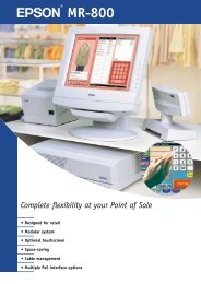
The MR is a modular-type POS terminal consisting of a base unit, which is the IM-800, and a<br />
display unit, which is the DM-M820. The IM-800 and the DM-M820 are also sold separately.<br />
IM-800 Features<br />
❏<br />
❏<br />
❏<br />
❏<br />
❏<br />
❏<br />
❏<br />
❏<br />
❏<br />
❏<br />
❏<br />
❏<br />
IBM ® PC/AT ® compatible<br />
Intel ® Celeron (FC-PGA/FC-PGA2 package) can be used. Either a 733 MHz or a 1.2 GHz<br />
Celeron is factory installed.<br />
Two 168-pin DIMM sockets are ready for installation of a maximum 512 MB of memory<br />
An LCD unit (DM-M820) exclusive to the MR can be connected<br />
A 3.5-inch floppy disk drive is available<br />
A 3.5-inch hard disk drive or two 2.5-inch hard disk drive is available<br />
A CD-ROM drive or CD-R/RW drive is available as a factory option<br />
An Ethernet controller for 10Base-T/100Base-TX is installed as standard equipment<br />
Four serial interface ports are provided<br />
One PCI slot is provided<br />
A power supply for a TM printer is provided (For the 24V model)*1<br />
Cables on the rear of the IM-800 can be covered by the included cable cover<br />
❏ A small footprint with maximum dimensions of 315 × 365 × 88 mm (W × D × H) {12.4 × 14.4<br />
× 3.5"} (including rear cover)<br />
DM-M820 Features<br />
*1 Applies only with the TM Printer Power Supply model.<br />
The DM-M820 is an LCD unit designed to be connected to an EPSON PC-POS system.<br />
❏<br />
❏<br />
❏<br />
❏<br />
❏<br />
800 × 600 dots resolution using a 12.1 inch color TFT LCD<br />
A tilt mechanism for easy positioning of the screen viewing angle<br />
A cable cover or a unified cable performs cable management effectively<br />
Display settings of the LCD and the brightness of the backlight can be adjusted.<br />
A stain-resistant touch panel is used.*1<br />
❏ Input by finger touch using the resistive film type of touch panel.*2<br />
❏ An MSR unit can read ISO/JIS Track 1, 2, or 3 (only for models with an MSR unit) *3<br />
Rev. I Features and Overview 1-1
❏<br />
Power is supplied from the IM-800 or the OI-MR01 AC Adapter. The AC Adapter is used if<br />
the DM-M820 is bought by itself instead of with an IM-800.<br />
*1 Applies only to models with a stain-resistant Touch Panel.<br />
*2 Applies only to models with a Touch Panel.<br />
*3 Applies only to models with an MSR, which is sold only with the IM-800.<br />
Model Configurations<br />
IM-800<br />
The MR is composed of the IM-800 and the DM-M820.<br />
CPU<br />
HDD<br />
CD-ROM drive<br />
733MHz, 1.2GHz<br />
One 3.5" HDD, Two 2.5" HDDs<br />
CD-ROM drive, CD-R/RW drive, Without<br />
Power Supply For the standardmodel 145W ATX Power supply<br />
Power Supply<br />
Speaker<br />
Withe the TM Printer<br />
Power Supply model<br />
With, Without<br />
180W ATX Power supply with 24V<br />
Case Color<br />
Epson cool white, Epson dark glay<br />
DM-M820<br />
MSR<br />
Touch Panel<br />
Back light<br />
Case Color<br />
AC Adapter<br />
With, Without<br />
With, Without<br />
2 lights*<br />
Epson cool white, Epson dark glay<br />
With sold only the DM-M820 model<br />
* The OLD model has 1 light.<br />
The IM-800 and the DM-M820 are sold separately, but the DM-820 model with MSR is sold only<br />
with the IM-800.<br />
1-2 Features and Overview Rev. I
MR Series <strong>Technical</strong> <strong>Reference</strong> <strong>Manual</strong><br />
Part Names for IM-800<br />
Front view<br />
USB ports<br />
Ventilation<br />
opening<br />
CD/FDD<br />
cover<br />
Power<br />
switch<br />
Power<br />
LED<br />
HDD LED<br />
With CD/FDD cover open<br />
CD-ROM FDD LED<br />
drive(option)<br />
CD-ROM<br />
LED<br />
CD-ROM Eject<br />
eject button hole<br />
FDD unit<br />
FDD eject<br />
button<br />
Rev. I Features and Overview 1-3
Rear Cover<br />
Rear cover<br />
Rear view(Standard model)<br />
COM2 port PCI slot COM3 port DC 12V output<br />
(for DM-M820)<br />
AC voltage<br />
select switch<br />
Mouse COM1 port<br />
Keyboard LPT port<br />
Display<br />
port<br />
Ethernet<br />
port<br />
USB port<br />
Line-out<br />
output<br />
Line-in<br />
input<br />
Mic input<br />
COM4 port<br />
AC Inlet<br />
Rear view(24V model)<br />
DC 24V output<br />
(for TM printer)<br />
COM2 port<br />
PCI slot COM3 port<br />
DC 12V output<br />
Mouse COM1 port<br />
Keyboard LPT port<br />
Display<br />
port<br />
Ethernet<br />
port<br />
USB port<br />
Line-out<br />
output<br />
Line-in<br />
input<br />
Mic input<br />
COM4 port<br />
AC Inlet<br />
1-4 Features and Overview Rev. I
MR Series <strong>Technical</strong> <strong>Reference</strong> <strong>Manual</strong><br />
.<br />
Inside view(for the Standard model)<br />
Rear Side<br />
COM Port Circuit<br />
Board Assembly<br />
PCI card<br />
CPU<br />
Power Supply<br />
DIMM<br />
CD-ROM Drive<br />
HDD<br />
Speaker<br />
(for the Speaker model)<br />
Front Side<br />
FDD<br />
Inside view(for the 24V model)<br />
Rear Side<br />
COM Port Circuit<br />
Board Assembly<br />
PCI card<br />
CPU<br />
DC 24V Board<br />
Power Supply<br />
DIMM<br />
CD-ROM Drive<br />
HDD<br />
Speaker<br />
(for the Speaker model)<br />
Front Side<br />
FDD<br />
Rev. I Features and Overview 1-5
Part Names for DM-M820<br />
Model with MSR<br />
LCD / touch<br />
panel*<br />
Function<br />
control buttons<br />
Adjustment<br />
control<br />
Power switch<br />
Power-On LED<br />
Card Slot**<br />
MSR unit**<br />
LED for MSR**<br />
Model without MSR<br />
LCD / touch<br />
panel*<br />
Function<br />
control buttons<br />
Adjustment<br />
control<br />
Power switch<br />
Power-On LED<br />
1-6 Features and Overview Rev. I
MR Series <strong>Technical</strong> <strong>Reference</strong> <strong>Manual</strong><br />
Rear view<br />
LCD stand<br />
Stand tab<br />
Cable A /<br />
Cable B /<br />
Cable C /<br />
Cable A (with a touch panel and an MSR)<br />
Display<br />
connector<br />
DC plug<br />
Serial port<br />
connector<br />
PS/2 keyboard<br />
connector for IM-800<br />
PS/2 keyboard<br />
connector for keyboard<br />
Rev. I Features and Overview 1-7
Cable B (without a touch panel and an MSR)<br />
Display<br />
connector<br />
DC plug<br />
Cable C (with a touch panel, without an MSR)<br />
Serial port<br />
connector<br />
DC plug<br />
Display<br />
connecter<br />
.<br />
AC Adapter (OI-MR01)<br />
Power LED<br />
AC inlet<br />
DC plug<br />
* Applies only to models with a touch panel.<br />
** Applies only to models with an MSR.<br />
1-8 Features and Overview Rev. I
MR Series <strong>Technical</strong> <strong>Reference</strong> <strong>Manual</strong><br />
Specifications<br />
IM-800<br />
Item<br />
Specifications<br />
CPU Usable CPU types *1) Celeron 733 MHz or 1.2 GHz<br />
Socket<br />
370-pin socket<br />
Memory Main memory *2) 168-pin DIMM slots × 2<br />
3.3V PC100 SDRAM / Maximum 512MB<br />
BIOS ROM<br />
512KB<br />
Chipset<br />
Video controller<br />
IO controller<br />
Intel 810E2 chipset<br />
Built-in chipset<br />
Winbond W83627F (controls FDD, COM1/2, PS/2, and parallel<br />
interface)<br />
ITE IT8872F (controls COM3/4)<br />
Mass storage FDD One 3.5" floppy drive (1.44MB / 720KB)<br />
HDD<br />
One 3.5" HDD or Two 2.5" HDD<br />
IDE interface / Ultra DMA/33/66/100<br />
CD-ROM drive<br />
A CD-ROM or CD-R/RW optionally installed in factory, IDE<br />
interface, can be set as boot drive<br />
Interface LAN (Ethernet) 10BASE-T/100BASE-TX is installed, "Wake On LAN" is<br />
supported.<br />
Interface Keyboard One PS/2-type (6-pin mini-DIN)<br />
Mouse<br />
Serial *3)<br />
Parallel<br />
Display<br />
USB *4)<br />
Audio<br />
DC12V output *5) *8)<br />
DC 24V output*8)<br />
One PS/2-type (6-pin mini-DIN)<br />
Four ports (9-pin D-sub male)<br />
+5V or +12V can be output to COM3 or COM4.<br />
One port (D-sub 25-pin female) SPP/EPP/ECP supported<br />
One port (D-sub 15-pin female)<br />
Two ports on the front and two ports on the rear.<br />
LINE IN, LINE OUT, microphone terminals<br />
One (+12V / 3A) for DM-M820<br />
One (+24V / 2A) for EPSON TM Printer<br />
Expansion slot PCI slot One slot (PCI version 2.2 compliant)<br />
Internal speaker *6)<br />
Audio function *6)<br />
Backup battery<br />
BIOS<br />
OS *7)<br />
Built-in monaural speaker<br />
AC'97 audio CODEC supported<br />
External line input/output, with a microphone terminal<br />
For the Lithium non-rechargeable battery the RTC and the<br />
RTC's built-in CMOS RAM when AC power is not supplied.<br />
Battery type: CR2032<br />
Battery life: Approximately 5 years<br />
ACPI 1.0b / APM 1.2 / Plug & Play / DMI<br />
Diagnostics Utility are supported<br />
MS-DOS, Windows 98, Windows NT, Windows 2000, Windows XP<br />
Rev. I Features and Overview 1-9
Item<br />
Specifications<br />
Lithium battery<br />
The IM-800 is internally equipped with a Lithium non-rechargeable<br />
battery that supplies the backup voltage to the RTC and the RTC's builtin<br />
CMOS RAM when AC power is not supplied. The battery can be<br />
exchanged easily because the battery is connected through the<br />
socket.<br />
Battery type: CR2032<br />
Battery life: Approximately 5 years<br />
Power supply<br />
Standard<br />
model<br />
Input voltage *8)<br />
145W ATX power supply is built in<br />
AC input voltage can be changed with a switch.<br />
Low range: 100-127 VAC / 3.5 A (max.)<br />
High range: 200-240 VAC / 2 A (max.)<br />
Frequency<br />
50 / 60 Hz<br />
24V<br />
model<br />
Input voltage *8)<br />
180W ATX power supply is built in<br />
100-127 VAC / 4 A (max.)<br />
200-240 VAC / 2 A (max.)<br />
Frequency<br />
50 / 60 Hz<br />
Case Size 315(W) × 280(D) × 88(H) mm (excluding the rear cover)<br />
{12.4 × 11 × 3.5"}<br />
315(W) × 365(D) × 88(H) mm (including the rear cover)<br />
{12.4 × 14.4 × 3.5"}<br />
Color<br />
Epson cool white<br />
Epson dark gray<br />
Environmental<br />
conditions<br />
Condition: Operating range Storage range<br />
Temperature: 5 to 35°C {41 to 95°F} –10 to 50°C {14 to 122°F}<br />
Humidity (RH): 30 to 80% non-condensing 30 to 90% non-condensing<br />
*1: The Celeron (533 MHz or less) with a PPGA package is not supported.<br />
*2: ECC is not supported.<br />
*3: If the COM3/4 is used, you need to install the serial driver from the Driver CD-ROM for the IM-800.<br />
*4: The USB interface is not supported with MS-DOS, or Windows NT. (The keyboard or mouse is supported with the BIOS.)<br />
*5: The LCD outlet must not be connected to a peripheral other than the DM-M820.·<br />
*6: The internal speaker is not supported by the onboard sound controller.(There is a model that can output sound through the<br />
internal speaker.)<br />
*7: There are some limitations with each OS. Refer to Chapter 4 “OS and Drivers.”<br />
*8: A switch to cut the AC power off is not available.<br />
1-10 Features and Overview Rev. I
MR Series <strong>Technical</strong> <strong>Reference</strong> <strong>Manual</strong><br />
DM-M820<br />
Item<br />
Specification<br />
LCD Size 12.1"<br />
Type<br />
Resolution<br />
Color<br />
Input signal<br />
Scanning frequency<br />
Dot clock frequency<br />
Color TFT<br />
800 × 600 dots<br />
262,144 colors<br />
(Can emulate 16 M color display using the dithering<br />
function)<br />
0.7V p-p, 75 ohm<br />
Horizontal 24 to 69KHz, Vertical 50 to 85 Hz<br />
Max. 80MHz<br />
View angle<br />
Horizontal<br />
direction<br />
From the left 45º (typ.) to the right 45º (typ.)<br />
Vertical direction<br />
From the top 30º (typ.) to the bottom 10º (typ.)<br />
Backlight<br />
Old Backlight<br />
Standard model<br />
Number of lamps<br />
Brightness<br />
1 lamp<br />
150 cd/m 2 min. (except touch panel)<br />
100 cd/m 2 min. (including touch panel)<br />
Life<br />
20,000 hours or more (at 25 ± 5°C {77 ± 9°F})<br />
Initial brightness reduced to half<br />
Backlight<br />
Standard model<br />
(Old Backlight<br />
High brightness<br />
model)<br />
Number of lamps<br />
Brightness<br />
Life<br />
2 lamp<br />
275 cd/m 2 min. (except touch panel)<br />
50,000 hours or more (at 25 ± 5°C {77 ± 9°F})<br />
Initial brightness reduced to half<br />
Touch panel*1 Method Resistive film (touch with finger)<br />
Surface solidity<br />
Positioning accuracy<br />
3H or more (JIS K-5400)<br />
±1.5 % maximum<br />
MSR*2 <strong>Support</strong>ed cards ISO 7811, JIS X6301 Type I tracks 1, 2, 3<br />
Reading direction<br />
<strong>Support</strong>ing MSR firmware<br />
Bidirectional<br />
Ver 3.04 or later<br />
External interface<br />
DC Jack, Serial port connector*1, Display connector,<br />
PS/2 connectors × 2 (for a PS/2 keyboard and the IM-<br />
800)*2<br />
Indicator With an MSR POWER LED, LED for MSR<br />
Without an MSR<br />
AC Adapter<br />
POWER LED<br />
POWER LED<br />
Power supply<br />
+12V (supplied through the DC cable from the IM-800<br />
or AC Adapter OI-MR01)<br />
Tilting angle From 0º to 90º<br />
Case color<br />
Epson cool white<br />
Epson dark gray<br />
Dimensions 320 × 340 × 200 mm (W × H × D) {12.6 × 13.4 × 7.9"}<br />
Rev. I Features and Overview 1-11
Item<br />
Mass<br />
Specification<br />
Approximately 5.0 kg {3.3 lb}<br />
Environmental conditions Condition: Operating range Storage<br />
range<br />
Temperature: 5 to 35°C {41 to 95°F} –10 to 50°C<br />
{14 to 122°F}<br />
Humidity (RH): 30 to 80% non-condensing 30 to 90%<br />
non-condensing<br />
The unit is not water resistant.<br />
Others<br />
Connection to the IM-800 through an exclusive DC<br />
cable.<br />
A button on the right side of the panel lets you adjust<br />
the backlight brightness.<br />
*1 Applies only to models with a touch panel.<br />
*2 Applies only to models with an MSR unit.<br />
AC Adapter (OI-MR01)*<br />
Item<br />
Input<br />
Frequency<br />
Output<br />
Protection<br />
function<br />
Over voltage protection<br />
function<br />
Circuit breaker<br />
Specification<br />
90 -264 VAC / 1.5 A (max.)<br />
47 -63 Hz<br />
12VDC / 3 A (max.)<br />
Built-in<br />
<strong>Manual</strong> reset<br />
Dimensions 110 × 62 × 33 mm (W × H × D) {4.3× 2.4 × 1.3"}<br />
* The AC Adapter is used if the DM-M820 without MSR model is used without an IM-800.<br />
1-12 Features and Overview Rev. I
MR Series <strong>Technical</strong> <strong>Reference</strong> <strong>Manual</strong><br />
Dimensions<br />
IM-800<br />
Dimensions:<br />
315 (W) × 280 (D) × 88 (H) mm {12.4 × 11 × 3.5"} (excluding the rear cover)<br />
315 (W) × 365 (D) × 88 (H) mm {12.4 × 14.4 × 3.5"} (including the rear cover)<br />
280<br />
365<br />
88<br />
(excluding the rubber feet)<br />
[Units : mm]<br />
315<br />
DM-M820<br />
340 mm<br />
250 mm<br />
200 mm<br />
305 mm<br />
320 mm<br />
Rev. I Features and Overview 1-13
Underside of Base<br />
The dotted circle is the position and size of the hole in the table required if the DM-M820 is<br />
mounted on a table with the cable going down rather than out of the back of the LCD stand.<br />
102<br />
70<br />
50<br />
200<br />
240<br />
1-14 Features and Overview Rev. I
Chapter 2<br />
Setup for the IM-800 and the DM-M820<br />
MR Series <strong>Technical</strong> <strong>Reference</strong> <strong>Manual</strong><br />
Setting the AC Voltage for the IM-800 (For the Standard model)<br />
If you are using 100-127 V power, set the AC<br />
voltage switch to 115. If you are using 200-240 V<br />
power, set the AC voltage switch to 230. (The<br />
factory setting is 230.) If the setting is wrong,<br />
the system will be damaged and will not<br />
operate.<br />
Follow these steps:<br />
1. Remove the warning sheet.<br />
2. Set the AC voltage select switch.<br />
IM-800 Installation Positions<br />
You can install the unit in either of the positions shown.<br />
The rubber feet are used only when the unit is installed<br />
horizontally. Attach the rubber feet to the indentations on<br />
the bottom of the unit.<br />
WARNING:<br />
If you set this product upright, be sure the ventilation opening is on the top. Do not place<br />
any object on top of the ventilation opening. If the ventilation opening is blocked, the<br />
product can be damaged by overheating.<br />
If you install this product horizontally, never place any object within 3 cm {1.2"} of the<br />
ventilation openings on the front, side, and rear. If the ventilation opening is blocked,<br />
the product can be damaged by overheating.<br />
Rev. I Setup for the IM-800 and the DM-M820 2-1
If the IM-800 is placed horizontally with the rear cover installed, attach the rubber feet<br />
that are included or leave at least 1 cm {0.4"} of space from the bottom of the rear<br />
cover.<br />
Installing face<br />
1cm or more<br />
Do not put anything that weighs more than 20 kg {44 lb} on the IM-800 when it is installed<br />
horizontally.<br />
Installing the DM-M820<br />
Cable Arrangement<br />
When you plan your installation of the DM-M820, consider the cable that comes out of the base.<br />
There are two ways you can arrange the cable:<br />
❏<br />
❏<br />
Make a hole in the surface on which you will place the unit and run the cable through the<br />
hole (A in the illustration below).<br />
Remove the tab from the back of the LCD stand and run the cable out of the back of the LCD<br />
stand (B in the illustration below).<br />
B<br />
A<br />
CAUTION:<br />
If burrs are left after the tabs are removed, they may cause cuts or scratches. Remove<br />
the burrs with a nipper or file.<br />
2-2 Setup for the IM-800 and the DM-M820 Rev. I
MR Series <strong>Technical</strong> <strong>Reference</strong> <strong>Manual</strong><br />
Connecting the DM-M820<br />
Be sure to unplug the power cable for the IM-800 or PC before you connect the cables for the<br />
DM-M820.<br />
Connectors on the IM-800<br />
Serial port connectors<br />
DC plug<br />
Keyboard out<br />
Display connector<br />
Connector Cables for a DM-M820 with a Touch Panel and MSR<br />
❏ DC plug Connects to the 12 VDC output of the IM-800.<br />
❏ Display connector Connects to the display port of the IM-800.<br />
❏<br />
Serial port connector Connects to the touch panel COM1 or COM2 port.<br />
Note:<br />
If you are using a DM-M820 with a touch panel, be sure to connect the serial port connector to<br />
COM1 or COM2. Do not use COM3 or COM4.<br />
Also if you are using a DM-M820 with a touch panel, do not install a mouse driver. Installing a<br />
mouse driver can prevent the touch panel from working.<br />
❏ Keyboard out Connects the keyboard out to the IM-800 keyboard port.<br />
Note:<br />
Be sure not to connect to the mouse port.<br />
❏ Keyboard in If you are using an external PS/2 keyboard, connect it to the keyboard<br />
in connector.<br />
Connector Cables for a DM-M820 with a Touch Panel and without an MSR<br />
❏ DC plug Connect to the 12 VDC output on the IM-800 or the AC adapter<br />
(OI-MR01).<br />
❏ Display connector Connect to the display port on the IM-800 or PC.<br />
❏<br />
Serial port connector Connect to the COM port for the touch panel on the IM-800 or PC.<br />
Rev. I Setup for the IM-800 and the DM-M820 2-3
Note:<br />
If you are using a DM-M820 with a touch panel, be sure to connect the serial port connector to<br />
COM1 or COM2. Do not use COM3 or COM4.<br />
Also if you are using a DM-M820 with a touch panel, do not install a mouse driver. Installing a<br />
mouse driver can prevent the touch panel from working.<br />
Connector Cables for a DM-M820 with No Touch Panel and No MSR<br />
❏ DC plug Connect to the 12 VDC output of the IM-800 or AC adapter<br />
(OI-MR01).<br />
❏ Display connector Connect to the display port of the IM-800 or PC.<br />
Connecting the Power Cable for AC Adapter<br />
Be sure to push the end of the power cable all the way into the AC inlet. The fitting on the power<br />
cable should make contact with the back of the inlet.<br />
CAUTION:<br />
Do not use the DC plug on a system other than the IM-800 or the OI-MR01 (AC adapter).<br />
The DC plug on the exclusive cable is designed only for the IM-800 or the OI-MR01 (AC<br />
adapter).<br />
IM-800 Connectors<br />
The illustration below shows all the connectors on the back of the IM-800. In addition, there are<br />
two USB connectors on the front. (See Chapter 1.)<br />
Be sure to unplug the power cable from the IM-800 before you connect these cables.<br />
Standard model<br />
COM2 PCI slot COM3 12 VDC output<br />
for DM-M820<br />
Mouse<br />
COM1<br />
Display<br />
Line-out<br />
Line-in<br />
Mic input<br />
AC Inlet<br />
Keyboard<br />
LPT<br />
Ethernet<br />
USB<br />
COM4<br />
2-4 Setup for the IM-800 and the DM-M820 Rev. I
MR Series <strong>Technical</strong> <strong>Reference</strong> <strong>Manual</strong><br />
With the TM Printer Power Supply model<br />
COM2 PCI slot COM3 12 VDC output<br />
for DM-M820<br />
Mouse<br />
COM1<br />
Display<br />
Line-out<br />
Line-in<br />
Mic input<br />
AC Inlet<br />
Keyboard<br />
LPT<br />
Ethernet<br />
COM4<br />
USB<br />
Connecting Other Peripheral Devices to the IM-800<br />
These are general instructions for the types of peripherals you may want to use.<br />
CAUTION:<br />
The12 VDC output is an exclusive power supply for the DM-M820. Do not use it for other<br />
peripheral devices.<br />
Serial Device Information<br />
If you use COM3 or COM4, you must install the serial driver from the driver CD-ROM for the<br />
IM-800, included with the IM-800.<br />
Either + 5 V or +12 V can be output to COM3 or COM4. See Appendix A, “Jumper Settings.”<br />
Connecting a Serial Modem to the IM-800<br />
If you are using a serial modem with the IM-800, be sure to connect the modem to COM1 or<br />
COM2. Do not use COM3 or COM4.<br />
USB Device Information<br />
There are four USB ports, two on the front and two on the back.<br />
You cannot use USB devices if you are using either MS-DOS or Windows NT.<br />
Rev. I Setup for the IM-800 and the DM-M820 2-5
Keyboard and Mouse<br />
To use a USB keyboard or mouse under MS-DOS or Windows NT, set USB keyboard support or<br />
USB mouse support in the Integral Peripheral section of the BIOS setup.<br />
Using a PS/2 mouse<br />
To use a PS/2 mouse, you must be sure that USB mouse support in the Integrated<br />
Peripheral section of the BIOS is set to Disabled (which is the factory setting).<br />
TM-Printer<br />
Use the dedicated power supply for the power supply of the TM-Printer. (For the standard<br />
model)<br />
Connect the power supply of the TM-Printer to the DC24V Output using the DC cable. (For the<br />
24V model)<br />
PCI Cards<br />
See the PCI information in Chapter 3, “Hardware Specifications,” and Chapter 9, “Disassembly<br />
and Assembly.”<br />
Connecting the Power Cable<br />
When AC power is supplied, a minute electric current flows through the IM-800. Therefore,<br />
before connecting peripherals and cables to this product, unplug the AC cord.<br />
WARNING:<br />
Never insert or disconnect the power plug with wet hands. Doing so may result in severe<br />
shock.<br />
Always supply power directly from a standard domestic power outlet.<br />
Do not place multiple loads on the power outlet (wall outlet). Overloading the outlet<br />
may lead to fire.<br />
The equipment must be installed near the electrical outlet, and the outlet must be easily<br />
accessible.<br />
Be sure your power cable meets the relevant safety standards and includes a power<br />
system ground terminal (PE terminal).<br />
2-6 Setup for the IM-800 and the DM-M820 Rev. I
MR Series <strong>Technical</strong> <strong>Reference</strong> <strong>Manual</strong><br />
Attaching the Rear Cover<br />
The rear cover makes the back of the system look neat and protects the cables.<br />
1. When you want the cables to exit the top of the rear cover, use pliers to break out the tabs.<br />
CAUTION:<br />
If burrs are left after the tabs are removed, they may cause cuts or scratches.<br />
Remove the burrs with a cutter or file.<br />
2. Remove the screw from the lower right corner of the back of the unit.<br />
3. Fit the tabs on the rear cover as shown below.<br />
tabs<br />
4. Attach with three screws, including the one you removed, in the locations shown below.<br />
Rev. I Setup for the IM-800 and the DM-M820 2-7
2-8 Setup for the IM-800 and the DM-M820 Rev. I
MR Series <strong>Technical</strong> <strong>Reference</strong> <strong>Manual</strong><br />
Chapter 3<br />
Hardware Specifications<br />
Hardware Block Diagram for IM-800<br />
Main Board<br />
I2C Bus<br />
Clock<br />
Generator<br />
ICS9248-9<br />
6<br />
66/100/133 MHz<br />
S-DRAM<br />
PC100<br />
DIMM 168<br />
Pins X 2<br />
CPU<br />
Socket 370<br />
HOST Bus<br />
810E<br />
GMCH<br />
(North Bridge)<br />
82810E<br />
VRM 8.5<br />
DC/DC<br />
ISL6524<br />
HDD Power<br />
FDD Power<br />
CD Power<br />
DC Jack Power<br />
VGA<br />
CRT<br />
ATX Power<br />
Supply Unit<br />
24V<br />
Output<br />
ATX 20 Pins<br />
Power Connector<br />
Power Button<br />
Power/HDD LED<br />
RTC<br />
Battery<br />
I2C Bus<br />
Hub Link<br />
ICH2<br />
(South Bridge)<br />
FW82801BA<br />
USB Port 0<br />
USB Port 1<br />
USB Port 2<br />
USB Port 3<br />
USB<br />
USB<br />
Pin<br />
Header<br />
Rear<br />
USB<br />
USB<br />
BOX Header<br />
Front<br />
RJ-45<br />
& LED<br />
PHY<br />
82562ET<br />
MAC<br />
PCI Bus<br />
PCI Bus<br />
MIC<br />
L_Out<br />
L_In<br />
CODEC<br />
AD1887<br />
AC Link<br />
Riser Board Slot<br />
FWH (BIOS)<br />
Firmware Hub<br />
512K Byte<br />
49LF004<br />
/ 82802AB<br />
ATA-33/66/100<br />
Primary IDE<br />
Secondary IDE<br />
SPKR<br />
1st IDE<br />
2nd IDE<br />
Low Profile<br />
PCI Slot<br />
Riser Board<br />
Standard<br />
PCI Slot<br />
FWH<br />
COM Board<br />
Keyboard<br />
Mouse<br />
COM1<br />
LPC Interface<br />
PS-2 Keyboard<br />
PS-2 Mouse<br />
COM 1<br />
LPC<br />
Super I/O<br />
Winbond<br />
W83627F<br />
QFP-128<br />
Beep<br />
Floppy<br />
Parallel<br />
Speaker<br />
FDD<br />
LPT<br />
+12V<br />
COM 3<br />
+5V<br />
ITE<br />
PCI<br />
Bridge<br />
+12V<br />
IT8872F COM 4<br />
+5V<br />
COM2<br />
COM 2<br />
CPU Fan<br />
System Fan<br />
+12V DC<br />
Jack for<br />
LCD<br />
Rev. I Hardware Specifications 3-1
DMA<br />
The IM-800 supports seven DMA channels. Channels 0, 1, 2, and 3 provide 8-bit data transfers;<br />
channels 4, 5, 6, and 7 provide 16-bit data transfers. The IM-800 uses channel 2 for the floppy<br />
disk drive controller and releases the other channels to the other devices. The following table<br />
lists the DMA channel allocation.<br />
DMA channels<br />
Controller Channel Application<br />
DMA1 8 bits 0 (Spare)<br />
1 (Spare*)<br />
2 Floppy disk drive controller<br />
3 (Spare*)<br />
DMA2 16 bits 4 Controller 1 cascade<br />
5 (Spare)<br />
6 (Spare)<br />
7 (Spare)<br />
* When LPT1 is in ECP mode, use one of these channels.<br />
System Interrupts<br />
The system connects 2 8259A-equivalent interrupt controllers in cascade and has 15 levels of<br />
interrupts, besides NMIs. The following table shows the application for each interrupt. Change<br />
the system interrupts with the BIOS setup program or Plug & Play function.<br />
System interrupts<br />
Controller 1 Controller 2 Application Changeable?<br />
IRQ0 Timer NO<br />
IRQ1 Keyboard NO<br />
IRQ2 Controller 2 cascade NO<br />
IRQ8 RTC NO<br />
IRQ9 Not used * 1 OK<br />
IRQ10 Not used *1 OK<br />
IRQ11 Not used * 1 OK<br />
IRQ12 Mouse NO<br />
IRQ13 Numerical operation coprocessor NO<br />
IRQ14 IDE controller (primary) * 2<br />
IRQ15 IDE controller (secondary) * 2<br />
IRQ3 Serial port 2 OK<br />
IRQ4 Serial port 1 OK<br />
IRQ5 Not used * 1 OK<br />
IRQ6 Floppy disk controller NO * 3<br />
IRQ7 Parallel port 1 OK<br />
NMI I/O error check NO<br />
* 1 PCI (for example, network) is automatically set through the detection of the unused interrupt level. If Serial port 3/<br />
4 is used with Windows, use an unused interrupt level. If Serial port 3/4 is used with DOS, Serial port 3 is set to IRQ11<br />
and Serial port 4 is set to IRQ10 automatically.<br />
* 2 Changes are not possible when the device is in use, but can be cleared when not in use.<br />
* 3 This can be set to “Not used” in the BIOS setup, but the IRQ is not released.<br />
3-2 Hardware Specifications Rev. I
MR Series <strong>Technical</strong> <strong>Reference</strong> <strong>Manual</strong><br />
Configuration of Circuit Boards<br />
Main Board<br />
Mouse<br />
Keyboard<br />
CPU Fan<br />
Connector<br />
System Fan<br />
Connector<br />
ATX Connector<br />
Power Switch<br />
Connector<br />
BIOS<br />
LED<br />
Connector<br />
Parallel<br />
COM1<br />
CRT<br />
CPU<br />
Socket<br />
(370-pin)<br />
FDD<br />
LAN<br />
USB x2<br />
Line-Out<br />
Line-In<br />
Mic-In<br />
COM2<br />
Header<br />
DIMM Sockets<br />
Secondary IDE<br />
Primary IDE<br />
CD Audio<br />
Header<br />
JP15<br />
Front USB<br />
Header<br />
JP10<br />
Riser Card Slot<br />
Speaker<br />
Connector<br />
Speaker<br />
RTC Battery<br />
COMS CLEAR Jumper<br />
Rev. I Hardware Specifications 3-3
Riser Board<br />
PCI Slot<br />
COM Board Slot<br />
COM Board<br />
DC12V Input<br />
Connector<br />
JP2 JP1<br />
COM3<br />
DC12V<br />
Jack<br />
COM4<br />
Header<br />
DC24V Board<br />
DC24V Jack<br />
DC24V Input<br />
Connector<br />
PCI Slot<br />
CAUTION:<br />
Before using a PCI card, it is your responsibility to examine it carefully to confirm whether<br />
its specifications conform to the specifications described in this manual.<br />
To get the latest information about which PCI board can be used with this product,<br />
contact your EPSON dealer.<br />
The PCI slot is located on the riser board.<br />
3-4 Hardware Specifications Rev. I
MR Series <strong>Technical</strong> <strong>Reference</strong> <strong>Manual</strong><br />
The dimensions of installable PCI cards are shown below:<br />
210<br />
<br />
Maximum height of parts: 14.48<br />
(maximum)<br />
106.68<br />
Maximum height of parts on the soldering face:<br />
2.67 (maximum)<br />
[Units:mm]<br />
Power Supply<br />
The IM-800 has an ATX power supply that switches the AC input by AC voltage select switch<br />
and does not have a switch to cut off the AC input.<br />
Standard model<br />
Input voltage:<br />
Input frequency:<br />
Input current:<br />
Cooling fan:<br />
MTBF:<br />
Low range 100 - 127 VAC (90 - 137 VAC)<br />
High range 200 - 240 VAC (180 - 265 VAC)<br />
50 ± 3 Hz / 60 ± 3 Hz<br />
3.5 A maximum (100 - 127 VAC)<br />
2 A maximum (200 - 240 VAC)<br />
Air intake type, fan rotation speed is automatically changed, depending on<br />
the temperature in the power supply unit.<br />
200,000 hours<br />
Precautions:<br />
1) Setting the AC input voltage switch improperly causes the following problems:<br />
If you use 100-127 V power when the switch is set to 230, the IM-800 will not operate, but if you<br />
change the setting to 115, the unit will operate.<br />
If you use 200-240 V power when the switch is set to 115, the voltage power unit will be<br />
damaged.<br />
2) When the protective circuit of the voltage power unit performs a shutdown, the protective<br />
circuit keeps working for a while. When this happens, unplug the power cable and wait for<br />
about 15 seconds; then plug the cable back in.<br />
Rev. I Hardware Specifications 3-5
24V model<br />
Input voltage/current:<br />
Input frequency:<br />
Cooling fan:<br />
depending on<br />
MTBF:<br />
100 - 127 VAC / 4A<br />
200 - 240 VAC / 2A<br />
50 ± 3 Hz / 60 ± 3 Hz<br />
Air intake type, fan rotation speed is automatically changed,<br />
the temperature in the power supply unit.<br />
200,000 hours<br />
Precautions:<br />
2) When the protective circuit of the voltage power unit performs a shutdown, the protective<br />
circuit keeps working for a while. When this happens, unplug the power cable and wait for<br />
about 15 seconds; then plug the cable back in.<br />
Power supply capacity for external devices<br />
Total power available to devices connected to the interface boards in the PCI slot, COM3/4,<br />
keyboard/mouse, and USB are as follows. Current drain must not exceed the capacity shown<br />
for each supply voltage: +5V, +3.3V, +12V, and -12V.<br />
Power supply Used for Capacity<br />
+5 VDC PCI slot, COM ports, keyboard/mouse, USB 2.0 A<br />
+3.3 VDC PCI slot 1.0 A<br />
+12 VDC PCI slot, COM ports 1.0 A<br />
-12 VDC PCI slot 0.02 A<br />
Each port has the following current limitation:<br />
Power Supply Capacities to Each Port<br />
Port Voltage Current supply capacity Remarks<br />
COM port +5 VDC 500 mA each (peak 1 A/100 ms) Total current of +5<br />
+12 VDC 500 mA each (peak 1 A/100 ms)<br />
VDC and +12 VDC<br />
must not exceed the<br />
value shown at left.<br />
USB port +5 VDC 500 mA each (peak 1 A/100 ms) --<br />
Keyboard and mouse +5 VDC 500 mA (peak 1A / 100 ms) --<br />
Power Supply for 24V model +24 VDC 2A (peak 1A / 100 ms) --<br />
3-6 Hardware Specifications Rev. I
MR Series <strong>Technical</strong> <strong>Reference</strong> <strong>Manual</strong><br />
Lithium Battery<br />
The IM-800 is internally equipped with a Lithium non-rechargeable battery, which supplies the<br />
backup voltage to the RTC and the RTC's built-in CMOS RAM (only when the AC power is not<br />
supplied). The battery can be exchanged easily because the battery is connected through the<br />
socket.<br />
Battery type: CR2032<br />
Vendor:<br />
Sony, Maxell, Toshiba<br />
Battery life:<br />
Approximately 5 years<br />
When replacing batteries, be sure to use the types and manufacturers listed above.<br />
MAC Address<br />
The MAC address label is attached on the LPT connector of the main board.<br />
Rev. I Hardware Specifications 3-7
3-8 Hardware Specifications Rev. I
MR Series <strong>Technical</strong> <strong>Reference</strong> <strong>Manual</strong><br />
Chapter 4<br />
OS and Drivers<br />
Outline of This Chapter<br />
This chapter tells which Operating Sytems and Drivers can be used and how to install and<br />
uninstall them.<br />
CAUTION:<br />
Don’t write anything, such as an application to an HDD that is removed from the MR.<br />
The vibration and impact can cause trouble and the failure of the HDD.<br />
Operating Systems<br />
The following Operating Systems can be used for the IM-800.<br />
❏<br />
❏<br />
Windows 2000 Professional (There is a version preinstalled by EPSON)<br />
Windows XP Professional<br />
❏ Windows 98SE (There is a version preinstalled by EPSON)<br />
❏<br />
❏<br />
Windows NT Workstation 4.0 SP6a<br />
MS-DOS Ver.6.22<br />
Drivers and Utilities<br />
Drivers for using the IM-800 are on the Driver CD-ROM included with the IM-800. If the<br />
operating system is pre-installed, the drivers are also installed.<br />
MSR utilities for the DM-M820 with MSR are on the Driver CD-ROM included with the IM-800,<br />
and if the operating system is pre-installed, the utilities are on the HDD. Set up the MSR using<br />
the utilities.<br />
Touch panel drivers for the DM-M820 with touch panel are on the touch panel driver CD-ROM<br />
for the DM-M820. Even if the operating system is preinstalled, you must install the touch panel<br />
drivers.<br />
Rev. I OS and Drivers 4-1
Driver CD-ROM for the IM-800<br />
The driver for installing a locally procured OS on the IM-800, the MSR utility for using the MSR<br />
of the DM-M820, and drivers for using the peripheral devices are on this CD-ROM.<br />
The CD-ROM directory is shown below.<br />
Root<br />
CDVER.TAG<br />
|--- DOS62 Drivers for MS-DOS<br />
| |--- Cdrom : CD-ROM drivers<br />
| |--- Network : Network drivers<br />
| |--- Serial : Serial drivers<br />
|--- WIN98 Drivers for Windows98<br />
| |--- Chipset : Chipset drivers<br />
| |--- Network : Network drivers<br />
| |--- Serial : Serial drivers<br />
| |--- Sound : Sound drivers<br />
| |---Video : Video drivers<br />
|--- WINNT Drivers for Windows NT<br />
| |--- Network : Network drivers<br />
| |--- Serial : Serial drivers<br />
| |--- Sound : Sound drivers<br />
| |---Video : Video drivers<br />
|--- WIN2K Drivers for Windows2000<br />
| |--- Chipset : Chipset drivers<br />
| |--- Network : Network drivers<br />
| |--- Serial : Serial drivers<br />
| |--- Sound : Sound drivers<br />
| |---Video : Video drivers<br />
|--- WINXP Drivers for Windows XP<br />
| |--- Serial : Serial drivers<br />
|--- COMMON Common OS utility drivers<br />
|--- Apdrv : Advanced Printer Drivers<br />
|--- Oposadk : OPOS-ADK<br />
|--- TmDrv : UniMini Drivers<br />
|--- MSRCFG : DM-MS Definition tool<br />
|--- WIN :<br />
|--- DISK1 :<br />
|--- DOS :<br />
Readme.txt files are in both the root directory and in subdirectories of the root directory.<br />
1. The Readme.txt file in the root directory contains an overview of this CD-ROM, and<br />
refers to the Readme.txt files in the various subdirectories.<br />
2. The Readme.txt files in the operating system subdirectories explain driver installation/<br />
un-installation for each operating system.<br />
3. Readme.txt files for MSRCFG, OPOS-ADK, and APDRV are included with the software.<br />
4-2 OS and Drivers Rev. I
Touch Panel driver CD-ROM for the DM-M820 touch panel model<br />
The CD-ROM directory is shown below.<br />
MR Series <strong>Technical</strong> <strong>Reference</strong> <strong>Manual</strong><br />
Root<br />
CDVER.TAG<br />
|--- DOS Touch Panel Driver for MS-DOS<br />
|--- WIN--- European Touch Panel Driver for Windows98/NT/2000/XP for European<br />
|--- Asian Touch Panel Driver for Windows98/NT/2000/XP for Chinese T/<br />
C,Korean<br />
Readme.txt files are in both the root directory and in subdirectories beneath the root directory.<br />
1. The Readme.txt file in the root directory contains an overview of this CD-ROM, and<br />
refers to the Readme.txt files in the various subdirectories.<br />
2. The Readme.txt files under the operating system subdirectories explain driver<br />
installation/un-installation for each operating system.<br />
Rev. I OS and Drivers 4-3
Windows 2000 Pre-Installed Model<br />
The exclusive EPSON utility and drivers for using IM-800 are pre-installed in the HDD with the<br />
pre-installed Windows 2000 Professional.<br />
Installation Procedure<br />
Windows 2000 Installation<br />
When turning on the power supply, the installation starts. Enter the product<br />
key of the W2K label pasted on the product. You can set up the Network<br />
automatically or set it up later.<br />
When using the DM-M820 with Touch Panel, follow the steps as below.<br />
Touch Panel Driver Installation<br />
Install the Touch Panel Driver from the CD-ROM for the DM-M820. See<br />
page 4-45 for the procedure.<br />
Change of Double click settings<br />
Set up this setting every time a new user starts using Windows 2000.<br />
MSR Utility Installation<br />
When using the DM-M820 with MSR, install the MSR utilities from<br />
C:\backup\msrcfg folder or the Driver CD-ROM for the IM-800.<br />
Other software Installation<br />
When using OPOS-ADK, APD (Windows printer drivers) and Unimini,<br />
install the software from the Driver CD-ROM for the IM-800.<br />
Formatting the hard disk<br />
The hard disk is composed of one partition of up to 10 GB as a system area. For a hard disk of<br />
more than 10 GB, the excess area other than the system area, is not yet formatted. This drive can<br />
be converted to NTFS using the Convert command. Use the disk administrator when creating a<br />
drive in the unused area. The start-up drive has been formatted to the following file system.<br />
• File system: FAT32<br />
• Volume label: Windows 2000<br />
4-4 OS and Drivers Rev. I
MR Series <strong>Technical</strong> <strong>Reference</strong> <strong>Manual</strong><br />
Pre-installed software<br />
❏ Microsoft Windows 2000 Professional<br />
❏ Microsoft Windows 2000 Service Pack 2<br />
❏<br />
❏<br />
❏<br />
❏<br />
❏<br />
❏<br />
Multilingual User Interface (French, German, Italian, Spanish, Dutch, Portuguese)<br />
Intel Chipset software installation utility<br />
Intel Video driver<br />
Intel Network driver<br />
Analog Devices Sound driver<br />
ITE COM3/4 Driver<br />
❏ EPSON DM-MS Series setup utility *1<br />
Version of the Pre-installation HDD<br />
To confirm the version of the HDD, see the file HDVER.TAG at the root directory of the boot<br />
drive. This file is text-formatted and can be read using Notepad or a similar text editor. The file<br />
HDVER.TAG has the following contents:<br />
[HD Information]<br />
MODEL=IM-800<br />
OS=Windows2000<br />
LANG=Dutch/English/French/German/Italian/Portuguese/Spanish<br />
VER=1.**.*<br />
Rev. I OS and Drivers 4-5
Directory Configuration<br />
The root directory of the HDD is structured as follows.<br />
|--- Backup<br />
| |--- Msrcfg : Backup of MSR Utility<br />
| | |--- Win :<br />
| | | |--- Disk1 : Backup of MSR Utility for Windows<br />
| | |--- DOS : Backup of MSR Utility for MS-DOS<br />
| |--- Chipset : Chipset driver backup folder<br />
| | |--- Win2000 :<br />
| |--- Network : Network driver backup folder<br />
| |--- Recovery : Recovery folder<br />
| |--- Serial : Serial port driver backup folder<br />
| |--- Sound : Sound driver backup folder<br />
| |--- Video : Video driver backup folder<br />
| |--- Win2ksp2 : Windows 2000 Service Pack 2 backup folder<br />
|--- BOOTDISK : Folder for files used to create an ordinary boot floppy disk<br />
|--- Documents and Settings: Folder for saving text and settings.<br />
|--- I386 : Setup file folder<br />
|--- Mui :<br />
|--- Program Files : Windows utility folders<br />
|--- WINNT : Windows folders<br />
The I386 directory may be deleted after the addition of the Windows 2000 application and the<br />
addition / change of the driver.<br />
The directories under the Backup directory are the backups for drivers and utilities. Each of<br />
these directories can be backed up into CD-R or other media. After being backed up, these<br />
directories may be deleted.<br />
Windows 2000 Setup Procedure<br />
CAUTION<br />
Because the touch panel is not operative during the setup procedure, be sure to keep<br />
the keyboard connected. If necessary, start the setup procedure after connecting the<br />
mouse.<br />
The keyboard is necessary for inputting the product ID and password. The keyboard is<br />
also necessary for user verification during logon to Windows 2000, even if the touch<br />
panel is in a usable state.<br />
Windows 2000 is setup by using the following procedure.<br />
1. Turn on the system, and boot the system from the pre-installation HDD. Windows 2000<br />
setup will start.<br />
2. The License Agreement screen is displayed. Check the contents, then select [I accept this<br />
agreement] and click Next.<br />
4-6 OS and Drivers Rev. I
MR Series <strong>Technical</strong> <strong>Reference</strong> <strong>Manual</strong><br />
3. The Regional Settings screen is displayed. Make sure the system locale, user locales and<br />
keyboard layout are set to United States, then click Next.<br />
4. The Personalize Your Software screen is displayed. Input the Name and Organization, then<br />
click Next.<br />
5. The Your Product Key screen is displayed. Input the product key entered on the cover of the<br />
First Step Guide in the COA (Certificate of Authenticity) package included with this<br />
product; then click Next.<br />
6. The Computer Name and Administrator Password screen is displayed. Input the Computer<br />
Name and Administrator Password, then click Next.<br />
7. The Date and Time Settings screen is displayed. Set the date and time, then click Next.<br />
8. The Networking Settings screen is displayed. Select either Typical Settings or Custom<br />
Settings according to the environment, then click Next. The Networking Components screen<br />
is displayed if Custom Settings is selected. Set the settings in accordance with the<br />
environment, then click Next.<br />
9. The Workgroup or Computer Domain screen is displayed. Set the settings in accordance<br />
with the environment, then click Next.<br />
The Performing Final Tasks screen is displayed, and setup starts.<br />
10. The Completing the Windows 2000 Setup Wizard screen is displayed. The system will start<br />
automatically when Finish is clicked.<br />
11. The Network Identification Wizard starts. Click Next.<br />
12. The Users of this Computer screen is displayed. Set the settings in accordance with the<br />
environment, then click Next.<br />
13. The Completing the Network Identification Wizard screen is displayed. Click Finish.<br />
14. Windows 2000 starts and the setup is completed.<br />
CAUTION:<br />
The setup is executed with the VGA display.<br />
Change of double click settings<br />
When you set up Windows 2000 and create a new user, you have to modify the registry key for<br />
individual users by following the steps below.<br />
Note<br />
The touch panel driver is not installed with the Operating System. After installing it from the touch panel<br />
driver CD-ROM for the DM-M820, set it up as follows.<br />
1. Select Programs - Gunze - U-TP - Settings in that order from the Start menu.<br />
Rev. I OS and Drivers 4-7
2. Pointer Device Properties is displayed. Click the Windows tab.<br />
3. Click the Defaults button on the Double Click Settings group box.<br />
4. Click OK.<br />
Installing the MSR Utility for Windows<br />
Install the MSR Utility by the following procedure.<br />
1. Start C:\Backup\Msrcfg\ Win\Disk1\SETUP.EXE.<br />
2. The Setup Wizard starts and the Welcome dialog box is displayed. Click Next.<br />
3. The Choose Destination Location dialog box is displayed. Specify the directory where the<br />
program is to be installed and click Next. C:\Program Files\MSR Config is specified as the<br />
default.<br />
4. Installing is completed, and the Setup dialog box is displayed. Click Finish.<br />
Uninstalling the MSR utility for Windows<br />
Uninstall the MSR Utility by the following procedure.<br />
1. Select [Start Menu] - [Settings] and open the control panel.<br />
2. Select [Add/Remove Hardware] in the control panel.<br />
3. Select [DM-MS Series Configuration Utilities].<br />
4. Click Add/Remove.<br />
5. The confirmation dialog box of the uninstalling is displayed. Select Yes.<br />
6. Uninstalling is completed, and the dialog box is displayed. Click OK.<br />
4-8 OS and Drivers Rev. I
Recovering the OS<br />
MR Series <strong>Technical</strong> <strong>Reference</strong> <strong>Manual</strong><br />
Use the OS recovery media (CD-ROM) packed with the IM-800 to recover the OS.<br />
Follow the steps below to carry out OS recovery.<br />
1. Turn power to the IM-800 off. Turn the main power switch off. Unplug the power cable.<br />
2. If a CD-ROM drive is not already installed, attach a drive to the MR series.<br />
3. Attach to the MR series the HDD unit you'd like to recover.<br />
4. Start up the BIOS setup utility and select the First Boot Device from the Advanced BIOS<br />
features setup menu.<br />
5. Set the First Boot Device to “CDROM”.<br />
6. Insert the “Windows 2000 CD-ROM 1 of 2" into the CD-ROM drive.<br />
7. On the BIOS setup utility main menu, select “Save & Exit Setup” and press the Enter key.<br />
The following dialog box appears.<br />
SAVE to CMOS and EXIT (Y/N)?<br />
8. Press [Y] and [Enter]. The system will restart and after a short time, the License Agreement<br />
will appear.<br />
Strike a key when ready ... _<br />
9. When you press any key, part of the License Agreement will appear. Repeat the same<br />
procedure until you get to the end of the License Agreement. The following message will<br />
appear.<br />
Please type following commands to start the OS recovery.<br />
A:\>_<br />
10. Enter the following from the command prompt.<br />
A:\>x: [enter]<br />
X:\>start [enter]<br />
11. The following message will appear. Select and enter the partition size of the HDD.<br />
Please select the system partition size.<br />
1: 10GB (Default size)<br />
F: Full size of HD.<br />
Please push a key of 1 or F._<br />
12. EPSON HDD Recovery Utility window will appear. Press Continue to start the OS<br />
recovery.<br />
OS recovery takes 20 to 40 minutes. The time differs depending on the type of OS and CPU<br />
speed.<br />
Rev. I OS and Drivers 4-9
13. The image data exchange dialog will appear. Insert the Windows 2000 CD-ROM 2 of 2 in the<br />
CD-ROM drive; then press the OK button.<br />
14. When the prompt below is displayed on the screen, OS recovery work is complete.<br />
X:\>_<br />
15. Eject the “Windows 2000 CD-ROM” from the CD-ROM drive.<br />
16. Reboot and start the BIOS setup utility.<br />
17. Return the First Boot Device in the Advanced BIOS features setup menu to the “Floppy”.<br />
18. On the main menu, select “Save & Exit Setup” and press the Enter key. The following dialog<br />
box appears.<br />
SAVE to CMOS and EXIT (Y/N) ?<br />
19. Press [Y] and [Enter]. The system will restart.<br />
20. Make sure the OS restarts. When using Windows, cancel work after the setup screen and<br />
end Windows.<br />
21. If a CD-ROM drive unit is attached in step 2., power off and detach the CD-ROM drive.<br />
Limitation<br />
❏ If you are starting from a hard disk, recovery cannot be performed. Be sure to perform<br />
recovery from the CD-ROM.<br />
4-10 OS and Drivers Rev. I
MR Series <strong>Technical</strong> <strong>Reference</strong> <strong>Manual</strong><br />
Windows 98 Pre-Installed Model<br />
The HDD pre-installed with Windows 98 Second Edition is also pre-installed with the EPSON<br />
utility software and drivers dedicated to the IM-800.<br />
Languages are English, French, German, Spanish, and Italian.<br />
Installation Procedure<br />
Windows 98 Installation<br />
When turning on the power supply, the installation starts. Enter the product<br />
key of the W98 label pasted on the product. You can setup the Network<br />
automatically or setup it later.<br />
Touch Panel Driver Installation<br />
In the case of the DM-M820 with Touch Panel, install the Touch Panel Driver<br />
from the CD-ROM for the DM-M820. See page 4-45 for the procedure.<br />
MSR Utility Installation<br />
When using the DM-M820 with MSR, install the MSR utilities from<br />
C:\backup\msrcfg folder or the Driver CD-ROM for the IM-800<br />
Other software Installation<br />
When using OPOS-ADK, APD (Windows printer drivers) and Unimini,<br />
install the software from the Driver CD-ROM for the IM-800.<br />
Formatting the hard disk<br />
The hard disk is composed of one partition of up to 10 GB as a system area. For a hard disk of<br />
more than 10 GB, the excess area other than the system area is not yet formatted. Use the FDISK<br />
and FORMAT command when creating a drive in the unused area. The start-up drive has been<br />
formatted to the following file system.<br />
• File system: FAT32<br />
• Volume label: Windows 98<br />
Pre-installed software<br />
❏ Microsoft Windows 98 Second Edition<br />
❏<br />
Intel Chipset software installation utility<br />
Rev. I OS and Drivers 4-11
❏<br />
❏<br />
❏<br />
❏<br />
Intel Video driver<br />
Intel Network driver<br />
Analog Devices Sound driver<br />
ITE COM3/4 Driver<br />
❏ EPSON DM-MS Series setup utility *1<br />
Note:<br />
*1: These are not installed during the auto installation procedure.<br />
Version of the pre-installation HDD<br />
To confirm the version of the HDD, see HDVER.TAG in the start-up drive root. This file is textformatted<br />
and can be read using Notepad or a similar text editor. The contents of HDVER.TAG<br />
are as follows:<br />
[HD Information]<br />
MODEL=IM-800<br />
OS= Windows98<br />
LANG=English<br />
VER=1.**.*<br />
Directory Configuration<br />
The root directory of the HDD is structured as follows:<br />
|--- Program Files : Application for the standard installation of Windows 98<br />
|--- Backup :<br />
| |--- Msrcfg : Backup of MSR Utility<br />
| | |--- Win :<br />
| | | |--- Disk1 : Backup of MSR Utility for Windows<br />
| | |--- DOS : Backup of MSR Utility for MS-DOS<br />
| |--- Chipset : Backup of Chipset driver<br />
| |--- Video : Backup of Display Driver<br />
| |--- Sound : Backup of Sound Driver<br />
| |--- Network : Backup of Network Driver<br />
| |--- Serial : Backup of Serial Driver<br />
| |--- Recovery :<br />
| |--- Data : Backup of HD (for creating Recovery Media)<br />
| | |--- Restore : EasyRestore<br />
| |--- Bootfd : Start-up FD<br />
| |--- Data : Data of Start-up FD<br />
|--- My Documents :<br />
|--- Windows : Windows 98 Second Edition system<br />
The directories under the Backup directory are the backups for drivers and utilities. Each of<br />
these directories can be backed up onto CD-R or other media. After backup, the directories<br />
under the Backup directory may be deleted.<br />
4-12 OS and Drivers Rev. I
MR Series <strong>Technical</strong> <strong>Reference</strong> <strong>Manual</strong><br />
Windows 98 Set-Up Procedure<br />
Windows 98 is set up by using the following procedure:<br />
1. Connect the keyboard and mouse to the IM-800.<br />
2. Turn on the PC to start Windows 98 SE.<br />
3. The Enter Network Password dialog box is displayed. Input the password and click OK.<br />
4. The Welcome screen is displayed. Input the necessary information and click Next.<br />
5. The Windows End User license Agreement is displayed. Read it though and confirm your<br />
agreement to the terms. And then select [I accept this agreement] and click Next to proceed.<br />
6. The Windows Product Key screen is displayed. Input the 25-digit product key shown on the<br />
COA (Certificate of Authenticity). Click Next to begin setup. If you enter an incorrect key, a<br />
message is displayed indicating that. Select [Re-enter valid product key] and then click Next<br />
to return to the Windows Protect Key screen and input the product key again.<br />
7. When setup is completed, the Congratulations screen is displayed. Click Finish.<br />
8. The system asks you to set the Date and Time properties. Check the properties displayed,<br />
and change them as needed. Click Close to confirm the settings.<br />
9. The system setting is automatically updated, the system is rebooted, and the Windows 98 SE<br />
desktop appears.<br />
Installing the MSR Utility for Windows<br />
Install the MSR Utility by the following procedure.<br />
1. Start C:\Backup\Msrcfg\ Win\Disk1\SETUP.EXE.<br />
2. The Setup Wizard starts and the Welcome dialog box is displayed. Click Next.<br />
3. The Choose Destination Location dialog box is displayed. Specify the directory where the<br />
program is to be installed and click Next. C:\Program Files\MSR Config is specified as the<br />
default.<br />
4. Installing is completed, and the Setup dialog box is displayed. Click Finish.<br />
Uninstalling the MSR Utility for Windows<br />
Uninstall the MSR Utility by the following procedure.<br />
1. Select [Start Menu] - [Settings] and open the control panel.<br />
2. Select [Add/Remove Programs] in the control panel.<br />
3. Select [DM-MS Series Configuration Utilities].<br />
4. Click Add/Remove.<br />
Rev. I OS and Drivers 4-13
5. The confirmation dialog box of the uninstalling is displayed. Select Yes.<br />
6. Uninstalling is completed, and the dialog box is displayed. Click OK.<br />
<strong>Support</strong> Information<br />
Select the My Computer icon on the desktop, click the right mouse button and select Properties<br />
from the pull down menu.<br />
Click the <strong>Support</strong> Information button; the information on the contact is displayed.<br />
Recovering the OS<br />
Preparing recovery media<br />
❏<br />
Preparing a start-up disk<br />
1. Start the command prompt.<br />
2. Go to the C:\backup\recovery\bootfd directory.<br />
3. Execute MKDISK.bat.<br />
4. Insert a floppy disk in the FDD.<br />
5. Press Enter to start formatting.<br />
6. A message asking whether you are going to format another floppy disk is displayed.<br />
Press N. Then the necessary files are copied onto the floppy disk.<br />
7. A message that the copying is over is displayed. Then exit MS-DOS.<br />
❏<br />
Saving the HD image data<br />
Save all data under the C:\backup\recovery\data directory onto another medium or drive.<br />
Example:<br />
1. Connect the IM-800 in network to a PC that can write data onto CD-Rs.<br />
2. Save all data under the C:\backup\recovery\data directory of the IM-800 onto the PC.<br />
4-14 OS and Drivers Rev. I
MR Series <strong>Technical</strong> <strong>Reference</strong> <strong>Manual</strong><br />
3. Write all data saved in step 2 onto a CD-R.<br />
4. After saving the data, the directory under the C:\backup\recovery directory may be<br />
deleted.<br />
❏<br />
Backing up each driver<br />
Each directory under the C:\backup directory is the backup of each driver, which can be<br />
backed up through individual saving.<br />
Recovering method<br />
❏<br />
Editing the start-up disk<br />
Edit CONFIG.SYS and AUTOEXE.BAT created in “Preparing a Recovery Medium” to the<br />
device on which the image data has been saved.<br />
❏<br />
Recovering<br />
Restrictions<br />
❏<br />
1. Connect the medium or drive onto which the data has been saved in “Preparing a<br />
Recovery Medium” to the IM-800.<br />
2. Start the system by using the start-up floppy disk created in “Preparing a Recovery<br />
Medium.”<br />
3. Enter “x: [enter]” (x: Drive with the image file).<br />
4. The following message appears. Select and enter the partition size of the HDD.<br />
Please select the system partition size.<br />
1: 10GB (Default size)<br />
F: Full size of HD.<br />
Please push a key of 1 or F._<br />
5. Execute Start.bat.<br />
6. Following the title “EasyRestore,” the EPSON Logo Startup screen is displayed. Select<br />
Continue.<br />
7. After the OS is recovered, set up the OS.<br />
8. Return the printer driver for OPOS and Windows saved in “Preparing a Recovery<br />
Medium.”<br />
The size of the image data to be saved amounts to 500–600 MB. Saving this much data<br />
requires a large-capacity device, such as a CD-R, MO, or server.<br />
❏<br />
❏<br />
❏<br />
Because of restrictions by EasyRestore, the HD image data file (HDIMG003.PQI) cannot be<br />
divided.<br />
Because EasyRestore runs only on MS-DOS, it is a requirement of “Saving of HD Image<br />
Data” that MS-DOS can recognize the saving destination device.<br />
When startup is initiated from the built-in hard disk of the IM-800, recovery is impossible.<br />
Rev. I OS and Drivers 4-15
Installation for Windows XP Professional Locally Procured Edition<br />
Installation Procedure<br />
If you install Windows XP Professional locally procured edition, follow the steps below.<br />
Windows XP Professional Installation<br />
Insert the Windows XP startup disk and CD-ROM; then turn on the IM-800 to<br />
perform the setup. Enter the product key of the COA package. You can set up<br />
the Network automatically or set it up later.<br />
Serial port Driver Installation<br />
Install the software from the Driver CD-ROM for the IM-800.<br />
When using the DM-M820 with Touch Panel, follow the steps below.<br />
Touch Panel Driver Installation<br />
Install the Touch Panel Driver from the CD-ROM for the DM-M820. See<br />
page 4-45 for the procedure.<br />
The double click setting<br />
Set up this setting every time a new user starts using Windows XP.<br />
MSR Utility Installation<br />
When using the DM-M820 with MSR, install the MSR utilities from the<br />
CD-ROM for the IM-800. See page 4-50 for the procedure.<br />
Other software Installation<br />
When using OPOS-ADK, APD (Windows printer drivers) and Unimini,<br />
install the software from the Driver CD-ROM for the IM-800.<br />
Setup procedure<br />
Windows XP is set up by using the following procedure:<br />
1. Connect the keyboard and mouse to the IM-800.<br />
2. Insert the CD-ROM of Windows XP in the CD-ROM drive and boot up the system.<br />
3. The [Welcome to Setup] screen is displayed. Press the Enter key.<br />
4-16 OS and Drivers Rev. I
MR Series <strong>Technical</strong> <strong>Reference</strong> <strong>Manual</strong><br />
4. The [END-USER LICENSE AGREEMENT] screen is displayed. Read it through and confirm<br />
contents. If you agree with them, press the F8 key.<br />
5. Select the partition to set up Windows, and press the Enter key. When an unformatted<br />
partition is selected, a confirmation screen is displayed. Execute the format according to the<br />
instructions on the screen. After that, copying of the file starts.<br />
6. Reboot the system again according to the instructions on the screen.<br />
7. The [Regional and Language Options] dialog box is displayed. Confirm the setting contents<br />
and click Next.<br />
8. The [Personalize Your Software] dialog box is displayed. Input your name and your<br />
organization, and then click Next.<br />
9. The [Your Product key] dialog box is displayed. Input the 25-digit product key shown on the<br />
COA (Certificate of Authenticity) and click Next.<br />
10. The [Computer Name and Administrator Password] dialog box is displayed. Input the<br />
necessary information and click Next.<br />
11. The [Date and Time Settings] dialog box is displayed. Confirm the setting and click Next.<br />
12. The [Networking Settings] dialog box is displayed. Select the Typical settings or the Custom<br />
settings, and click Next.<br />
13. The [Workgroup or Computer Domain] dialog box is displayed. Select the correct item for<br />
the environment and click Next.<br />
14. The system reboots automatically.<br />
15. The [Welcome to Microsoft Windows] dialog box is displayed. Click Next.<br />
16. Set for Internet access according to the instruction on the screen.<br />
17. Proceed with the activate Windows according to the instruction on the screen.<br />
18. Input the user name according to the instruction on the screen.<br />
19. The [Thank you!] dialog box is displayed. Click Finish; Windows XP will start.<br />
CAUTION:<br />
Setup is executed with the VGA display.<br />
Installing the Serial Port Driver<br />
Note<br />
COM1/COM2 can be used without installing the driver. If you use COM3/COM4, you need to install the<br />
driver.<br />
If the standby mode of the Operating System is selected, the current mode automatically changes to the<br />
standby mode even if the data is being output to COM ports.<br />
1. Insert the Driver CD-ROM for the IM-800 in the CD-ROM drive.<br />
Rev. I OS and Drivers 4-17
2. Select [Start Menu] and open the control panel.<br />
3. Select [Printers and Other Hardware] in the control panel.<br />
4. Select [System] in the [See Also].<br />
5. The System dialog is displayed. Select the [Hardware] tab.<br />
6. Click Device Manager.<br />
7. Select [Other Devices] - [PCI Serial Port] in the list, and click Properties.<br />
8. The Properties dialog box is displayed. Click Reinstall Driver.<br />
9. The [Welcome to the Hardware Update Wizard] dialog box is displayed. Select the "Install<br />
from a list or specific location" checkbox and click Next.<br />
10. The [Hardware Installation] dialog box is displayed. Click Continue Anyway.<br />
11. The [Completing the Hardware Update Wizard] dialog box is displayed. Click Finish.<br />
12. Next the Serial Port 1 is automatically recognized and the [Welcome to the Found New<br />
Hardware Wizard] dialog box is displayed. Select the "Install the software automatically"<br />
check box and click Next.<br />
13. The [Hardware Installation] dialog box is displayed. Click Continue Anyway.<br />
14. The [Completing the Found New Hardware Wizard] dialog box is displayed. Click Finish.<br />
15. Next the Serial Port 2 is automatically recognized and the [Welcome to the Found New<br />
Hardware Wizard] dialog box is displayed. Select the "Install the software automatically"<br />
check box and click Next.<br />
16. The [Hardware Installation] dialog box is displayed. Click Continue Anyway.<br />
17. The [Completing the Found New Hardware Wizard] dialog box is displayed. Click Finish.<br />
Uninstalling the serial port driver<br />
Uninstalling cannot be done.<br />
Installing the Touch Panel Driver, MSR Utility and the Other Devices<br />
See the Installation of Other Drivers section on page 4-45.<br />
4-18 OS and Drivers Rev. I
MR Series <strong>Technical</strong> <strong>Reference</strong> <strong>Manual</strong><br />
Installation for Windows 2000 Professional Locally Procured Edition<br />
Installation Procedure<br />
If you install Windows 2000 Professional locally procured edition, follow the steps below.<br />
Windows 2000 Professional Installation<br />
Insert the Windows 2000 startup disk and CD-ROM; then turn on the IM-800<br />
to perform the setup. Enter the product key of the COA package. You can set<br />
up the Network automatically or set it up later.<br />
Chipset Driver Installation<br />
Install the Chipset Driver from the Driver CD-ROM for the IM-800.<br />
Network Driver Installation<br />
VIDEO Driver Installation<br />
Sound Driver Installation<br />
Serial port Driver Installation<br />
Install the software from the Driver CD-ROM for the IM-800.<br />
When using the DM-M820 with Touch Panel, follow the steps below.<br />
Touch Panel Driver Installation<br />
Install the Touch Panel Driver from the CD-ROM for the DM-M820. See<br />
page 4-45 for the procedure.<br />
The double click setting<br />
Set up this setting every time a new user starts using Windows 2000.<br />
MSR Utility Installation<br />
When using the DM-M820 with MSR, install the MSR utilities from the<br />
CD-ROM for the IM-800. See page 4-50 for the procedure.<br />
Other software Installation<br />
When using OPOS-ADK, APD (Windows printer drivers) and Unimini,<br />
install the software from the Driver CD-ROM for the IM-800.<br />
Rev. I OS and Drivers 4-19
Setup procedure<br />
Windows 2000 is set up by using the following procedure:<br />
1. Connect the keyboard and mouse to the IM-800.<br />
2. Insert the CD-ROM of Windows 2000 in the CD-ROM drive and boot up the system.<br />
3. The Setup Wizard starts, and the Welcome dialog box is displayed. Select [Install a new copy<br />
of Windows 2000], and then click Next.<br />
4. The License Agreement is displayed. Read it through and confirm your agreement to the<br />
terms. And then select [I accept the agreement] and click Next.<br />
5. The Your Product Key screen is displayed. Input the 25-digit product key shown on the<br />
COA (Certificate of Authenticity). Click Next to begin setup.<br />
6. Input the necessary information and continue the installation according to the instruction on<br />
the screen.<br />
7. When copy of the file is completed, reboot the system again according to the instruction on<br />
the screen.<br />
8. After rebooting the system, continue the installation according to the instruction on the<br />
screen.<br />
9. Reboot the system again according to the instruction on the screen.<br />
10. After the system setting is automatically updated, input the necessary information and<br />
continue the installation according to the instruction of the screen.<br />
11. The installation is completed, then click Finish according to the instruction on the screen.<br />
12. After the system is rebooted, the Network Identification wizard is started. Click Next.<br />
13. Set the Password according to the instruction on the screen.<br />
14. The installation is completed, and the desktop screen of Windows 2000 is displayed.<br />
CAUTION:<br />
Setup is executed with the VGA display.<br />
Note<br />
By default, it is impossible to recover from the standby mode with touch panel, keyboard and PS/2 mouse.<br />
Follow the steps below to set the power management.<br />
1. Open Start-Settings-Control Panel.<br />
2. Double-click System in the Control Panel.<br />
4-20 OS and Drivers Rev. I
MR Series <strong>Technical</strong> <strong>Reference</strong> <strong>Manual</strong><br />
3. The System Properties dialog box appears. Click the Hardware tab.<br />
4. Click the Device Manager button.<br />
5. The Device Manager dialog box appears. Select the keyboard as shown in the illustration<br />
below and click the Properties button in the tool bar. Or right click to show the short-cut<br />
menu; then select Properties.<br />
Rev. I OS and Drivers 4-21
6. The keyboard dialog box appears. Click the Power Management tab. Check the Allow this<br />
device to bring the computer out of standby box and click OK.<br />
Installing the Intel Chipset Diver<br />
This is installed by the exclusive installation program.<br />
1. Insert the Driver CD-ROM for the IM-800 in the CD-ROM drive. Start<br />
Win2K\Chipset\SETUP.EXE.<br />
2. The Setup Wizard starts and the Welcome screen is displayed. Click Next.<br />
3. The License Agreement screen is displayed. Click Yes.<br />
4. The Readme.txt dialog box is displayed. Click Next.<br />
5. Reboot dialog box is displayed. Confirm that [Yes, I want to restart my computer now] is<br />
selected, and click Finish to reboot the system.<br />
Uninstalling the Intel chipset driver<br />
Uninstalling cannot be done.<br />
Installing the Network Driver<br />
This is installed by the exclusive installation program.<br />
1. Insert the Driver CD-ROM for the IM-800 in the CD-ROM drive. Start<br />
Win2K\Network\100PDISK.EXE.<br />
4-22 OS and Drivers Rev. I
2. The dialog box to confirm copying the file is displayed. Click Yes.<br />
MR Series <strong>Technical</strong> <strong>Reference</strong> <strong>Manual</strong><br />
3. The Setup Wizard starts, the License Agreement dialog box is displayed. Select [I accept the<br />
terms in the license agreement] and click Next.<br />
4. The dialog box which specifies the place of the copy of the file is displayed. Input the place<br />
and click Next. The default setting is C:\Intel_32.<br />
5. When copying of the file is completed, the Release note is displayed.<br />
6. Select [Start Menu] - [Settings] and open the control panel.<br />
7. Select [System] in the control panel.<br />
8. The System dialog box is displayed. Select the [Hardware] tab.<br />
9. Click Device Manager.<br />
10. Select [Other Device] - [Ethernet Controller] in the list, and click Properties.<br />
11. The Properties dialog is displayed. Click Reinstall Driver.<br />
12. The Upgrade Device Driver Wizard dialog box is displayed. Click Next.<br />
13. The dialog box that specifies the search method of the driver is displayed. Confirm that<br />
[Search for a suitable driver for my device] is selected and click Next.<br />
14. The dialog box that specifies the place of the search of the driver file is displayed. Check<br />
[Specify a location] and click Next.<br />
15. The dialog box for the location the driver file is displayed. Input the directory specified by<br />
step 4, and click OK. The default setting is C:\INTEL_32.<br />
16. The confirmation dialog box of the device is displayed. Confirm that the [Intel(R) PRO/<br />
100VE Network Connection] is selected, and click Next.<br />
17. Installing of the driver is completed, the dialog box is displayed. Click Finish.<br />
18. The Intel(R) PRO/100 VE Network Connection Properties dialog box is displayed. Set up<br />
necessary items and click Close.<br />
Uninstalling the network driver<br />
1. Select [Start Menu] - [Settings] and open the control panel.<br />
2. Select [Add/Remove Hardware] in the control panel.<br />
3. Add/Remove Hardware Wizard starts and the Welcome dialog box is displayed. Click<br />
Next.<br />
4. The Choose a Hardware Task dialog box is displayed. Select Uninstall/Unplug a device,<br />
and click Next.<br />
5. The Choose a Removal Task dialog box is displayed. Select [Uninstall a device], and click<br />
Next.<br />
6. Select Intel(R) PRO/100 VE Network Connection in the list and Click Next.<br />
Rev. I OS and Drivers 4-23
7. The confirmation dialog box of the uninstalling is displayed. Select that the [Yes, I want to<br />
uninstall this device], and click Next.<br />
8. Uninstalling is completed and the dialog box is displayed. Click Finish.<br />
Installing the Display Driver<br />
This is installed by the exclusive installation program.<br />
1. Insert the Driver CD-ROM for the IM-800 in the CD-ROM drive. Start<br />
Win2K\Video\Win2K-XPE66.EXE.<br />
2. The Release note is displayed. Click Next.<br />
3. The Setup Wizard starts and the Welcome dialog box is displayed. Click Next.<br />
4. The License Agreement dialog box is displayed. Click Yes.<br />
5. Installing is completed and the reboot dialog box is displayed. Confirm that [Yes, I want to<br />
restart my computer now] is selected, and click Finish to reboot the system.<br />
Uninstalling the display driver<br />
Uninstalling cannot be done.<br />
Installing the Sound Driver<br />
This is installed by the exclusive installation program.<br />
1. Insert the Driver CD-ROM for the IM-800 in the CD-ROM drive. Start<br />
Win2K\Sound\SETUP.EXE.<br />
2. The Setup Wizard starts and the Welcome dialog box is displayed. Click Next.<br />
3. The reboot dialog box is displayed. Confirm that [Yes, I want to restart my computer now] is<br />
selected, and click Finish to reboot the system.<br />
Uninstalling the sound driver<br />
1. Select [Start Menu] - [Settings] and open the control panel.<br />
2. Select [Add/Remove Hardware] in the control panel.<br />
3. Add/Remove Hardware Wizard starts and the Welcome dialog box is displayed. Click<br />
Next.<br />
4. The Choose a Hardware Task dialog box is displayed. Select [Uninstall/Unplug a device],<br />
and click Next.<br />
5. The Choose a Removal Task dialog box is displayed. Select [Uninstall a device], and click<br />
Next.<br />
6. Select [SoundMAX Integrated Digital Audio] in the list and Click Next.<br />
7. The confirmation dialog box of the uninstalling is displayed. Select [Yes, I want to uninstall<br />
this device] and click Next.<br />
4-24 OS and Drivers Rev. I
MR Series <strong>Technical</strong> <strong>Reference</strong> <strong>Manual</strong><br />
8. Uninstalling is completed and the dialog box is displayed. Click Finish.<br />
Installing the Serial Port Driver<br />
Note<br />
COM1/COM2 can be used without installing the driver. If you use COM3/COM4, you need to install the<br />
driver.<br />
If the standby mode of the Operating System is selected, the current mode automatically changes to the<br />
standby mode even if the data is being output to COM ports.<br />
1. Insert the Driver CD-ROM for the IM-800 in the CD-ROM drive.<br />
2. Select [Start Menu] - [Settings] and open the control panel.<br />
3. Select [System] in the control panel.<br />
4. The System dialog is displayed. Select the [Hardware] tab.<br />
5. Click Device Manager.<br />
6. Select [Other Device] - [PCI Serial Port] in the list, and click Properties.<br />
7. The Properties dialog box is displayed. Click Reinstall Driver.<br />
8. The Upgrade Device Driver Wizard dialog box is displayed. Click Next.<br />
9. The dialog box which specifies the search method of the driver is displayed. Confirm that<br />
[Search for a suitable driver for my device] is selected and click Next.<br />
10. The dialog box which specifies the place of the search of the driver file is displayed. Check<br />
[Specify a location] and click Next.<br />
11. The dialog box for the location of the driver file is displayed. Input D:\Win2K\Serial to the<br />
directory and click OK.<br />
12. The confirmation dialog box of the device is displayed. Confirm that the [PCI Serial Port] is<br />
selected and click Next.<br />
13. When installation of the driver is completed, a dialog box is displayed. Click Finish.<br />
14. The ITE8872 Properties dialog box is displayed. Set up necessary items and click Close.<br />
Uninstalling the serial port driver<br />
Uninstalling cannot be done.<br />
Installing the Touch Panel Driver, MSR Utility and the Other Devices<br />
See the Installation of Other Drivers section on page 4-45.<br />
Rev. I OS and Drivers 4-25
Installation for Windows NT Locally procured edition<br />
Note<br />
If you use Windows NT, you need to install Service Pack 6a.<br />
Installation Procedure<br />
If you install Windows NT Local procured edition, follow the steps below.<br />
Operating System Installation<br />
Inseert the CD-ROM for Windows NT and turn on the IM-800 to perform the<br />
setup. Enter the product key of the COA package. You can set up the Network<br />
automatically or set it up later.<br />
Network Driver Installation<br />
Install the software from the Driver CD-ROM for the IM-800.<br />
Service Pack 6a Installation<br />
Obtain Service Pack 6a and install it.<br />
Set the HDD to the DMA mode by using Service pack 6a.<br />
VIDEO Driver Installation<br />
Sound Driver Installation<br />
Serial port Driver Installation<br />
Install the software from the Driver CD-ROM for the IM-800.<br />
When using the DM-M820 with Touch Panel, follow the steps below.<br />
Touch Panel Driver Installation<br />
Install the Touch Panel Driver from the CD-ROM for the DM-M820. See<br />
page 4-45 for the procedure.<br />
MSR Utility Installation<br />
When using the DM-M820 with MSR, install the MSR utilities from the<br />
CD-ROM for the IM-800. See page 4-50.<br />
Other software Installation<br />
When using OPOS-ADK, APD (Windows printer drivers) and Unimini,<br />
install the software from the Driver CD-ROM for the IM-800.<br />
4-26 OS and Drivers Rev. I
MR Series <strong>Technical</strong> <strong>Reference</strong> <strong>Manual</strong><br />
Setup procedure<br />
Windows NT is set up by using the following procedure:<br />
1. Connect the keyboard and mouse to the PC.<br />
2. Insert the CD-ROM of Windows NT in the CD-ROM drive and boot up the system.<br />
3. The Welcome to Setup screen dialog box is displayed. Press the Enter key.<br />
4. According to the instructions on the screen, input the necessary items and continue<br />
installing.<br />
5. The Windows NT Licensing Agreement dialog box is displayed. Press the PageDown key<br />
and confirm contents to the last page. Press the F8(I agree) key.<br />
6. According to the instructions on the screen, input the necessary items and continue<br />
installing.<br />
7. When copying of the file is completed, according to the instruction on the screen, take the<br />
Windows NT CD-ROM out of the CD-ROM drive, and then boot the system from the HDD.<br />
8. The Windows NT Setup Wizard starts. According to the instruction on the screen, insert the<br />
CD-ROM of Windows NT to the CD-ROM drive again and click OK.<br />
9. According to the instruction of the screen, input the necessary items and continue installing.<br />
10. The Registration dialog box is displayed. Input the 10-digit CD key shown on the COA<br />
(Certificate of Authenticity). Select Next to begin setup.<br />
11. According to the instruction of the screen, input the necessary items and continue installing.<br />
12. According to the instruction of the screen, set up the date /time and the display.<br />
13. When installing is completed, according to the instruction of the screen, click Restart<br />
Computer and the system is rebooted. The desktop screen of Windows NT is displayed.<br />
CAUTION:<br />
Setup is executed with the VGA display.<br />
Installing the Network Driver<br />
This is installed by the exclusive installation program.<br />
1. Insert the Driver CD-ROM for the IM-800 in the CD-ROM drive. Start<br />
Winnt\Network\100PDISK.EXE.<br />
2. The dialog box to confirm copy the file is displayed. Click Yes.<br />
3. The Setup Wizard starts and the License Agreement dialog box is displayed. Select [I accept<br />
the terms in the license agreement] and click Next.<br />
Rev. I OS and Drivers 4-27
4. The dialog box which specifies the place of the copy of the file is displayed. Input the place<br />
and click Next. The default setting is C:\Intel_32.<br />
5. When copying of the file is completed, the Release note is displayed.<br />
6. Open the Control Panel, and select Network. A dialog box is displayed. Click Yes.<br />
7. The Network Setup Wizard starts. Check the [Wired to the Network] check box, and click<br />
Next.<br />
8. Click Select from list.<br />
4-28 OS and Drivers Rev. I
MR Series <strong>Technical</strong> <strong>Reference</strong> <strong>Manual</strong><br />
9. Click Have Disk.<br />
10. The Insert Disk dialog box is displayed. Input the directory specified by step 4, and click OK.<br />
The default setting is C:\INTEL_32.<br />
11. The Select OEM option dialog box is displayed. Confirm that [Intel(R) PRO Adapter] is<br />
selected, and click OK.<br />
12. The Intel(R) PRO Adapter is added to the network adapter. Click Next.<br />
13. Select the network protocol. Set it to your system. Then click Next.<br />
Rev. I OS and Drivers 4-29
14. Select the network service. Set it to your system. Then click Next.<br />
15. The following dialog box is displayed. When Next is clicked, installation starts.<br />
16. The dialog box that specifies the directory of the copy origin is displayed. Insert the<br />
CD-ROM of Windows NT in the CD-ROM drive and input D:\ (if the CD-ROM drive is the<br />
D drive) and click OK.<br />
17. In accordance with the environment used, continue the installation according to the<br />
instruction on the screen.<br />
18. When installing is completed, according to the instruction of the screen, reboot the system.<br />
CAUTION:<br />
If the network is installed after the setup, an error is caused in the logon procedure. After<br />
installing the network driver, install the Service Pack 6a.<br />
4-30 OS and Drivers Rev. I
MR Series <strong>Technical</strong> <strong>Reference</strong> <strong>Manual</strong><br />
Uninstalling the network driver<br />
Uninstalling cannot be done.<br />
Installing Service Pack 6a<br />
This is installed by the exclusive installation program.<br />
1. Insert the Service Pack 6a CD-ROM in the CD-ROM drive. Execute the<br />
“Nt4sp6\Sp6i386.exe” on the Service Pack 6a CD-ROM.<br />
2. The Setup Wizard starts, the License Agreement dialog box is displayed. Select [Accept the<br />
license agreement] and click Install.<br />
3. Installing is completed; then the dialog box is displayed. Click Restart.<br />
Ultra DMA Setting for the HDD<br />
You can set the HDD to the DMA mode by following the steps below.<br />
1. Set the Service Pack 6a CD-ROM to the CD-ROM drive. Execute the<br />
“Nt4sp6\<strong>Support</strong>\Utils\I386\Dmacheck.exe” in the Service Pack 6a CD-ROM.<br />
2. ATAPI DMA <strong>Support</strong> dialog box appears. Set the DMA Detection Status of the Current<br />
DMA Usage Channel 0 to enabled and click OK.<br />
3. A warning dialog box appears. Click Yes.<br />
Rev. I OS and Drivers 4-31
4. A finished dialog box appears. Click OK.<br />
5. The system reboots.<br />
Installing the Display Driver<br />
Before installing the display driver, be sure to install Service Pack 6a.<br />
This is installed by the exclusive installation program.<br />
1. Set the Driver CD-ROM for the IM-800 to the CD-ROM drive. Start<br />
Winnt\Video\Winnt4E66.EXE.<br />
2. The Release note is displayed. Click Next.<br />
3. The Setup Wizard starts. The Welcome dialog box is displayed. Click Next.<br />
4. The License Agreement dialog box is displayed. Click Yes.<br />
5. Installing is completed and the InstallShield Wizard Complete dialog box is displayed.<br />
Confirm that the [Yes, I want to restart my computer now] is selected, and click Finish to<br />
reboot the system.<br />
Uninstalling the display driver<br />
Uninstalling cannot be done.<br />
Installing the Sound Driver<br />
This is installed by the exclusive installation program.<br />
1. Insert the Driver CD-ROM for the IM-800 in the CD-ROM drive. Start<br />
Winnt\Sound\SETUP.EXE.<br />
2. The Setup Wizard starts and the Welcome dialog box is displayed. Click Next.<br />
3. The About SoundMAX Integrated Digital Audio dialog box is displayed. Click OK.<br />
4. The Setup Complete dialog box is displayed. Confirm that [Yes, I want to restart my<br />
computer now] is selected, and click Finish to reboot the system.<br />
Uninstalling the sound driver<br />
1. Select [Start Menu] - [Settings] and open the control panel.<br />
2. Select [Add/Remove Programs] in the control panel.<br />
3. Select [SoundMAX NT].<br />
4-32 OS and Drivers Rev. I
MR Series <strong>Technical</strong> <strong>Reference</strong> <strong>Manual</strong><br />
4. Click Add/Remove.<br />
5. The Confirm File Deletion dialog box is displayed. Click Yes.<br />
6. Uninstalling is completed and the dialog box is displayed. Click OK.<br />
7. The reboot dialog box is displayed. Click OK.<br />
8. Reboot the system.<br />
Installing the Serial Port Driver<br />
This is installed by the exclusive installation program.<br />
Note<br />
COM1/COM2 can be used without installing the driver. If you use COM3/COM4, you need to install the<br />
driver.<br />
1. Insert the Driver CD-ROM for the IM-800 in the CD-ROM drive. Start<br />
Winnt\Serial\SETUP.EXE.<br />
2. The Setup Wizard starts and the Software License Agreement dialog box is displayed. Click<br />
Yes.<br />
3. The Information dialog box is displayed. Click Next.<br />
4. The Setup Complete dialog box is displayed. Click Finish.<br />
5. The Reboot dialog box is displayed. Confirm that [Yes, I want to restart my computer now]<br />
is selected, and click Finish.<br />
Uninstalling the serial port driver<br />
1. Select [Start Menu] - [Settings] and open the control panel.<br />
2. Select [Add/Remove Programs] in the control panel.<br />
3. Select [ITE887X Uninstall].<br />
4. Click Add/Remove.<br />
5. The confirmation dialog box of the uninstalling is displayed. Click OK.<br />
6. The Reboot dialog box is displayed. Click Yes.<br />
Installing the Touch Panel Driver, MSR Utility and the Other Devices<br />
See the MSR Utility Installation on page 4-50 and the Installation of Other Drivers section on<br />
page 4-45.<br />
Rev. I OS and Drivers 4-33
Installation for Windows 98 Locally Procured Edition<br />
Installation Procedure<br />
If you install Windows 98 Locally procured edition, follow the steps below<br />
Windows 98 Installation<br />
Inseert the MS-DOS startup disk and CD-ROM for Windows 98 and turn on<br />
the IM-800 to perform the setup. Enter the product key of the COA package.<br />
You can set up the Network automatically or set it up later.<br />
Chipset Driver Installation<br />
Install using the Driver CD-ROM for the IM-800.<br />
Ultra DMA Setting for the HDD<br />
Set the HDD to the DMA mode with OS.<br />
Network Driver Installation<br />
VIDEO Driver Installation<br />
Sound Driver Installation<br />
Serial port Driver Installation<br />
Install the software from the Driver CD-ROM for the IM-800.<br />
When using the DM-M820 with Touch Panel, follow the steps below.<br />
Touch Panel Driver Installation<br />
Install the Touch Panel Driver from the CD-ROM for the DM-M820. See<br />
page 4-45for the procedure.<br />
MSR Utility Installation<br />
When using the DM-M820 with MSR, install the MSR utilities from the Driver<br />
CD-ROM for the IM-800.<br />
Other software Installation<br />
When using OPOS-ADK, APD (Windows printer drivers) and Unimini,<br />
install the software from the Driver CD-ROM for the IM-800.<br />
4-34 OS and Drivers Rev. I
MR Series <strong>Technical</strong> <strong>Reference</strong> <strong>Manual</strong><br />
Setup Procedure<br />
Windows 98 is set up by using the following procedure:<br />
1. Connect the keyboard and mouse to the PC.<br />
2. Insert the Startup disk of the MS-DOS to the FDD. Turn on the power supply to the system.<br />
3. Insert the CD-ROM of Windows 98 in the CD-ROM drive and start the SETUP.EXE. The<br />
Setup Wizard starts.<br />
4. The License Agreement is displayed. Read it through and confirm your agreement to the<br />
terms. And then select [I accept the agreement] and select Next to proceed.<br />
5. The Windows Product Key screen is displayed. Input the 25-digit product key shown on the<br />
COA (Certificate of Authenticity). Select Next to begin setup. If you enter an incorrect key, a<br />
message is displayed indicating that. Select Re-enter valid product key and then select Next<br />
to return to the Windows Protect Key screen ad input the product key again.<br />
6. According to the instruction on the screen, input the necessary items and continue installing.<br />
7. When copying of the file is completed, take the Setup disk of the MS-DOS out of the FDD,<br />
and then according to the instruction on the screen, reboot the system.<br />
8. After rebooting the system, according to the instruction of the screen, set up the Network<br />
and the Date/Time.<br />
9. According to the instruction on the screen, reboot the system.<br />
10. Drivers for the system are installed by Plug and Play. According to the instruction on the<br />
screen, input the necessary items and continue installing.<br />
11. When installing is completed, and according to the instruction on the screen, click Finish.<br />
The desktop screen is displayed.<br />
CAUTION:<br />
Setup is executed with the VGA display.<br />
Installing the Chipset Driver for Intel<br />
This is installed by the exclusive installation program.<br />
1. Insert the Driver CD-ROM for the IM-800 in the CD-ROM drive and start<br />
\Win98\Cipset\SETUP.EXE.<br />
2. The Setup Wizard starts and the Welcome screen is displayed. Click Next.<br />
3. The License Agreement screen is displayed. Click Yes.<br />
4. The Readme.txt dialog box is displayed. Click Next.<br />
Rev. I OS and Drivers 4-35
5. The Reboot dialog box is displayed. Confirm that the [Yes, I want to restart my computer<br />
now] is selected, and click Finish.<br />
6. After the system is restarted, the Chipset drivers are installed.<br />
7. After installation, according to the instruction on the screen, reboot the system.<br />
Uninstalling the chipset driver for Intel<br />
Uninstalling cannot be done.<br />
Ultra DMA Setting for the HDD<br />
You can set the HDD to the DMA mode by following the steps below.<br />
1. Select [Start Menu] - [Settings] and open the control panel.<br />
2. Select [System] in the control panel.<br />
3. The system Properties dialog box appears. Click the [Device Manager] tab.<br />
4. Select “GENERIC IDE DISK TYPE47” from [Disk drives] and click Properties.<br />
5. The GENERIC IDE DISK TYPE47 Properties dialog box appears. Click the [Settings] tab.<br />
4-36 OS and Drivers Rev. I
MR Series <strong>Technical</strong> <strong>Reference</strong> <strong>Manual</strong><br />
6. Check [DMA] in the [Option] group box.<br />
7. The following dialog box appears. Click OK.<br />
8. Click OK to close the GENERIC IDE DISK TYPE47 Properties dialog box.<br />
9. Click Close to close the System Properties dialog box.<br />
10. The following dialog box appears. Click Yes to restart the system.<br />
Installing the Network Driver<br />
This is installed by the exclusive installation program.<br />
1. Insert the Driver CD-ROM for the IM-800 in the CD-ROM drive. Start<br />
Win98\Network\100PDISK.EXE.<br />
2. The dialog box to confirm copy the file is displayed. Click Yes.<br />
3. The Setup Wizard starts and the License Agreement dialog box is displayed. Select [I accept<br />
the terms in the license agreement] and click Next.<br />
Rev. I OS and Drivers 4-37
4. The dialog box that specifies the location of the file is displayed. Input the place and click<br />
Next. The default setting is C:\Intel_32.<br />
5. When copy of the file is completed, the Release note is displayed.<br />
6. Select [Start Menu] - [Settings] and open the Control Panel.<br />
7. Select [System] in the control panel.<br />
8. The System dialog box is displayed. Click [Device Manager].<br />
9. Select [Other Device] - [PCI Ethernet Controller] in the list, and click Properties.<br />
10. The Properties dialog box is displayed. Click Reinstall Driver.<br />
11. The Update Device Driver Wizard dialog box is displayed. Click Next.<br />
12. The dialog box which specifies the search method of the driver is displayed. Confirm that<br />
[Search for a better driver than the one your device is using now] and click Next.<br />
13. The dialog box which specifies the place of the search of the driver file is displayed. Check<br />
[Specify a location] and click Next. Input the directory specified by step4, and Click Next.<br />
14. The confirmation dialog box of the device is displayed. Confirm that the [The updated<br />
driver Intel PRO/100VE Network Connection] is selected, and Click Next.<br />
15. The confirmation dialog box of the installation of the driver is displayed. Click Next.<br />
16. Another installation message is displayed. Click OK.<br />
17. The dialog box that specifies the location of the driver file is displayed. Input the directory<br />
specified by step 4 to [Copy files from], and Click OK.<br />
18. Installing of the driver is completed; then the dialog box is displayed. Click Finish.<br />
19. The dialog box requiring rebooting the system is displayed. Click Yes to reboot the system.<br />
Uninstalling the network driver<br />
1. Select [Start Menu] - [Settings] and open the control panel.<br />
2. Select [Add/Remove Programs] in the control panel.<br />
3. Select [Intel PRO Ethernet Adapter and Software].<br />
4. Click Add/Remove.<br />
5. The confirmation dialog box of the uninstalling is displayed. Click OK.<br />
6. The dialog box to reboot the system is displayed. Click Yes to reboot the system.<br />
4-38 OS and Drivers Rev. I
MR Series <strong>Technical</strong> <strong>Reference</strong> <strong>Manual</strong><br />
Installing the Display Driver<br />
This is installed by the exclusive installation program.<br />
1. Insert the Driver CD-ROM for the IM-800 in the CD-ROM drive and start<br />
\Win98\Video\Win9Xe66.EXE.<br />
2. The Readme.txt dialog box is displayed. Click Next.<br />
3. The Setup Wizard starts and the Welcome screen is displayed. Click Next.<br />
4. The License Agreement dialog box is displayed. Click Yes.<br />
5. Installing is completed and the Reboot dialog box is displayed. Confirm that [Yes, I want to<br />
restart my computer now] is selected, and click Finish to reboot the system.<br />
Uninstalling the display driver<br />
Uninstalling cannot be done.<br />
Installing the Sound Driver<br />
This is installed by the exclusive installation program.<br />
1. Insert the Driver CD-ROM for the IM-800 in the CD-ROM drive. Start<br />
Win98\Sound\SETUP.EXE.<br />
2. The Setup Wizard starts and the Welcome dialog box is displayed. Click Next.<br />
3. The reboot dialog box is displayed. Confirm that the [Yes, I want to restart my computer<br />
now] is selected, and click Finish to reboot the system.<br />
4. The Sound Driver is installed after the system is rebooted.<br />
5. Another message box is displayed. Click OK.<br />
6. The dialog box that specifies the lication of the driver file is displayed. Input<br />
D:\Win98\Sound\Smax\WDM\SE to [Copy files from] (If the CD-ROM drive is the D<br />
drive). Click OK and installing is completed.<br />
Uninstalling the sound driver<br />
1. Select [Start Menu] - [Settings] and open the control panel.<br />
2. Select [Add/Remove Hardware] in the control panel.<br />
3. Select [SoundMAX].<br />
4. Click Add/Remove.<br />
5. The confirmation dialog box of the uninstalling is displayed. Select [Remove] and click Next.<br />
Rev. I OS and Drivers 4-39
6. The reboot dialog box is displayed. Confirm that [Yes, I want to restart my computer now] is<br />
selected, and click Finish.<br />
Installing the Serial Port Driver<br />
Note<br />
COM1/COM2 can be used without installing the driver. If you use COM3/COM4, you need to install the<br />
driver.<br />
If the standby mode of the Operating System is selected, the current mode automatically changes to the<br />
standby mode even if the data is being output to COM ports.<br />
1. Insert the Driver CD-ROM for IM-800 in the CD-ROM Drive. Execute \Win98\<br />
serial\setup.exe.<br />
Uninstalling the serial port driver<br />
1. Select [Start Menu] - [Settings] and open the control panel.<br />
2. Select [Add/Remove Programs] in the control panel.<br />
3. Select [ITE887X].<br />
4. Click Add/Remove.<br />
5. The confirmation dialog box of the uninstalling is displayed. Click OK.<br />
6. The reboot dialog box is displayed. Click Yes.<br />
Installing the Touch Panel Driver, MSR Utility and the Other Devices<br />
See the Installation of Other Drivers section on page 4-45.<br />
4-40 OS and Drivers Rev. I
MR Series <strong>Technical</strong> <strong>Reference</strong> <strong>Manual</strong><br />
Installation for MS-DOS Locally Procured Version<br />
Installation Procedure<br />
If you install MS-DOS Locally procured version, follow the steps below.<br />
Operating System Installation<br />
Insert the MS-DOS startup disk and turn on the IM-800 to perform the Setup.<br />
As for the installation procedure, refer to the MS-DOS manual.<br />
CD-ROM Driver Installation<br />
As for installing MS-DOS only, the CD-ROM drive for the IM-800 is not<br />
recognized. Therefore, by using other PC to read the CD-ROM, install the<br />
CD-ROM driver in the IM-800 after copying the CD-ROM driver on the<br />
floppy disk from the Driver CD-ROM for the IM-800.<br />
Network Driver Installation<br />
The Network Driver is provided in the form compressed in the Driver<br />
CD-ROM for the IM-800, but MS-DOS cannot extract the compressed file.<br />
Therefore, by using other PC to read the CD-ROM, install the Network driver<br />
toin the IM-800 after extracting the Network driver in the Driver CD-ROM for<br />
the IM-800.<br />
Serial port Driver Installation<br />
Install the file to the IM-800 from the Driver CD-ROM for the IM-800.<br />
When using the DM-M820 with Touch Panel, follow the steps as below.<br />
Touch Panel Driver Installation<br />
Install the Touch Panel Driver from the CD-ROM for the DM-M820. See<br />
page 4-49.<br />
MSR Utility Installation<br />
When using the DM-M820 with MSR, install the MSR Utilities from the Driver<br />
CD-ROM for the IM-800. See page 4-51.<br />
Rev. I OS and Drivers 4-41
Installing the CD-ROM Driver<br />
After installing the MS-DOS locally procured edition only, the CD-ROM drive of the IM-800 is<br />
not recognized. Therefore, use other PC to read the CD-ROM, and install the CD-ROM driver to<br />
the IM-800 after copying the CD-ROM driver to a floppy disk from the Driver CD-ROM for the<br />
IM-800.<br />
Note<br />
When using the CD-ROM driver, MSCDEX.EXE of MS-DOS is needed.<br />
Install the CD-ROM driver by the following procedure.<br />
1. Start the other PC to read the CD-ROM, and insert the Driver CD-ROM for the IM-800 to the<br />
CD-ROM drive. Insert a formatted floppy disk in the FDD.<br />
2. Copy \Dos62\CD-ROM\CDATAPI.SYS in the Driver CD-ROM for the IM-800 to the floppy<br />
disk.<br />
3. Turn on the IM-800 to start MS-DOS.<br />
4. Insert the floppy disk copied by step 2 in the FDD of the IM-800.<br />
5. Copy the CDATAPI.SYS on the floppy disk to the optional directory in the hard disk. For<br />
example, copy it on C:\DOS\directory.<br />
6. Add the following description to the CONFIG.SYS of MS-DOS with a text editor, and save it.<br />
The following example is for copying to the C:\DOS\directory. In case of copying to other<br />
directory, describe the directory name with its full path.<br />
DEVICE=C:\DOS\CDATAPI.SYS /D:CDROM<br />
7. Add the following description to the AUTOEXEC.BAT of the MS-DOS with a text editor,<br />
and save it. The following example has MSCDEX.EXE in the C:\DOS\directory. If you have<br />
it in another directory, describe the directory with its full path. In case of the /L option,<br />
specify a drive name. The following is an example specifying the D drive. In case of<br />
specifying the other drive name, describe the optional drive name.<br />
C:\DOS\MSCDEX.EXE /D:CDROM /L:D<br />
8. Restart MS-DOS.<br />
Installing the Network Driver<br />
The Network Driver is provided in the form compressed in the Driver CD-ROM for the IM-800.<br />
MS-DOS cannot extract the compressed file. Therefore, by using another PC to read the<br />
CD-ROM, install the Network driver to the IM-800 after extracting the Network driver in the<br />
Driver CD-ROM for the IM-800.<br />
Note<br />
Windows 98, NT or 2000 is necessary for extracting the compressed file.<br />
Extracting the network driver<br />
Extract the compressed file of the Network Driver by the following procedure.<br />
1. Start the other PC to read the CD-ROM, and start either Windows 98, NT, or 2000.<br />
4-42 OS and Drivers Rev. I
MR Series <strong>Technical</strong> <strong>Reference</strong> <strong>Manual</strong><br />
2. Insert the Driver CD-ROM for the IM-800 in the CD-ROM drive.<br />
3. Start \Dos62\Network\100PDISK.EXE.<br />
4. The dialog box to confirm copying the file is displayed. Click Yes.<br />
5. The Setup Wizard starts, and the License Agreement dialog box is displayed. Select [I accept<br />
the terms in the license agreement] and click Next.<br />
6. The dialog box that specifies the place of the copy of the file is displayed. Input the place and<br />
click Next. The default setting is C:\Intel_32.<br />
7. When copying of the file is completed, the Release note is displayed.<br />
Installing the network driver<br />
Note<br />
Different environments require different ways of setting the Network Driver. For the details of the<br />
installation procedure, see the setting manual (HTML style) in the C:\Intel_32\Info\ directory in the file<br />
extracted by the preceding procedure.<br />
The following example describes the procedure to install the Netware DOS ODI Client Driver.<br />
1. Copy all files in the C:\Intel_32\DOS\ directory in the file extracted by the preceding<br />
procedure on the floppy disk.<br />
2. Turn on the IM-800 to start MS-DOS.<br />
3. Insert the floppy disk copied by step 1 in the FDD of the IM-800.<br />
4. Copy all files in the floppy disk to the optional directory in the hard disk. For example, copy<br />
it to the C:\NWCLIENT\ directory.<br />
5. Add the following description to the CONFIG.SYS of the MS-DOS with a text editor, and<br />
save it.<br />
LASTDRIVE=Z<br />
6. Edit the following description in C:\NWCLIENT\NET.CFG with a text editor, and save it.<br />
The following is the example of the setting for the NET.CFG.<br />
LINK DRIVER E100BODI<br />
FRAME ETHERNET_802.2<br />
SPEED=100<br />
PROTOCOL IPX EO Ethernet_802.2<br />
NETWARE DOS REQUESTER<br />
FIRST NETWORK DRIVE = F<br />
PB BUFFERS = 10<br />
Rev. I OS and Drivers 4-43
7. Add the following description to the AUTOEXEC.BAT of MS-DOS with a text editor, and<br />
save it. The following is the example of the having the driver file in the C:\NWCLIENT\<br />
directory. In case of having it in the other directory, describe as "CD [the directory name]".<br />
CD NWCLIENT<br />
LSL<br />
E100BODI<br />
IPXODI<br />
NETX<br />
8. Turn off the IM-800 and connect it to the network.<br />
9. Turn on the IM-800 and restart MS-DOS.<br />
Installing the Serial Port Driver<br />
Note<br />
COM1/COM2 can be used without installing this driver. In case of using COM3/COM4, it is necessary<br />
to install this driver.<br />
For installing this driver, it is necessary for the CD-ROM drive to work normally.<br />
Install the serial port driver by the following procedure.<br />
1. Turn on the IM-800 and start MS-DOS.<br />
2. Insert the Driver CD-ROM for the IM-800 in the CD-ROM drive.<br />
3. Copy \Dos62\Serial\ITE.COM to the optional directory in the hard disk. For example,<br />
copy it to the C:\DOS\ directory.<br />
4. Input the following form the command prompt of the MS-DOS and start it.<br />
C:\ITE.COM [COM3=xxxx] [COM4=yyyy]<br />
The parameter means as follows.<br />
COM3=xxxx :This specifies the Port address of COM3.<br />
COM4=yyyy :This specifies the Port address of COM4.<br />
The parameter can be omitted. In this case, the following default value is set.<br />
COM3<br />
:3E8h/IRQ11<br />
COM4<br />
:2E8h/IRQ10<br />
5. Input the following from the command prompt of the MS-DOS to finish.<br />
C:\ITE.COM -r<br />
6. Input the following from the command prompt of the MS-DOS to display the Usage.<br />
C:\ITE.COM /?<br />
Installing the Touch Panel Driver, MSR utility and the Other Devices<br />
See the Installation of Other Drivers section on page 4-45.<br />
4-44 OS and Drivers Rev. I
MR Series <strong>Technical</strong> <strong>Reference</strong> <strong>Manual</strong><br />
Installation of Other Drivers<br />
Installing the Touch Panel Driver for Windows<br />
Note<br />
Be sure to set the touch panel driver to COM1 or COM2. COM3/COM4 cannot be used.<br />
This is installed by the exclusive installation program.<br />
1. Insert the touch panel driver CD-ROM for DM-M820 in the CD-ROM drive.<br />
European:<br />
Start \Win\european\SETUP.EXE.<br />
Chinese T/C,korean : Start \Win\asian\SETUP.EXE.<br />
2. Start the touch panel driver set up program. The Welcome screen is displayed. Click Next.<br />
3. The License Agreement dialog box is displayed. Confirm the contents, and if you agree, click<br />
Accept.<br />
4. The Select folder dialog box is displayed. Specify the installation destination program folder,<br />
click Next. Gunze\U-TP is specified as the default.<br />
5. The Select Destination Directory dialog box is displayed. Specify the directory where the<br />
program is to be installed, click Next. C:\Program Files\Gunze\U-UP is specified as the<br />
default.<br />
6. The Install system tray icons dialog box is displayed. Specify the registration of the utility<br />
icon on the Task tray or not. Click Next.<br />
Rev. I OS and Drivers 4-45
7. The Number of devices dialog box is displayed. Confirm the number 1 is specified. Click<br />
Next.<br />
8. The Desktop Segment dialog box is displayed. Specify the Device Segment (the range to<br />
allocate the touch panel), enter the optional panel name. Click Next. Whole Desktop is<br />
usually the best choice.<br />
4-46 OS and Drivers Rev. I
MR Series <strong>Technical</strong> <strong>Reference</strong> <strong>Manual</strong><br />
9. The Select Controller dialog box is displayed. Select the [Gunze,AHL,Serial]. Click Next.<br />
10. The Port dialog box is displayed. Specify the Serial Port. Check the Auto Detect box or enter<br />
the number of the COM port that you use. Click Next. Advanced is usually not needed.<br />
CAUTION:<br />
Be sure not to set the port to COM3/COM4.<br />
Rev. I OS and Drivers 4-47
11. The Ready to Install dialog box is displayed. Click Next.<br />
12. Installation ends and the Install Successful dialog box is displayed. Click Finish.<br />
13. After the installation, the dialog box is displayed. Click Yes.<br />
14. After rebooting the system, the calibration of the touch panel is executed automatically. See<br />
“Touch Panel Calibration.”<br />
Uninstalling the touch panel driver for Windows<br />
Uninstall the touch panel driver by the following procedure.<br />
1. Select [Start Menu] - [Settings] and open the control panel.<br />
2. Select [Add/Remove Programs] in the control panel.<br />
3. Select [Universal Pointer Device Driver].<br />
4-48 OS and Drivers Rev. I
MR Series <strong>Technical</strong> <strong>Reference</strong> <strong>Manual</strong><br />
4. Click Add/Remove.<br />
5. The Uninstall Universal Pointer Device Driver dialog box is displayed. Click Next.<br />
6. The Uninstall Completed dialog box is displayed. Click Finish.<br />
7. The dialog box to require rebooting the system is displayed. Click Yes and reboot the<br />
system.<br />
Installing the Touch Panel Driver for MS-DOS<br />
Note<br />
Be sure to set the touch panel driver to COM1 or COM2. COM3/COM4 cannot be used.<br />
This is installed by the exclusive installation program.<br />
1. Insert the touch panel driver CD-ROM for the DM-M820 to the CD-ROM drive. Start<br />
\Dos\INSTALL.EXE.<br />
2. The touch screen screen is displayed. Select AHL/AR5000 and Digitouch Controllers by<br />
using the cursor keys, and press Enter.<br />
3. The Installation Options screen is displayed. Normally, leave the default setting as it is. To<br />
change the setting, select the item to be selected by using the cursor keys, and press Enter.<br />
The setting contents are changed. Select Start Installation, and press Enter to start copying<br />
the file to C:\TOUCH directory.<br />
4. After copying is complete, press any key. The hardware setting is displayed.<br />
5. Press any key. Readme is displayed.<br />
6. Press Esc to terminate installation.<br />
7. Enter the following from the prompt to install the driver:<br />
For example: Set to COM2<br />
TTDOS 2 /I:3 Enter<br />
TBMOUSE 1 Enter<br />
TT-DOS Command Line<br />
TTDOS [Port] [/A:address] [/C:bbbb,p,s][/I]<br />
Port:<br />
Specifies the serial port [Default:1]<br />
/A:Address: Port address [Default: 3F8]<br />
/C:bbbb,p,d,s<br />
Communications parameters<br />
bbbb: Baudrate [Default: 9600]<br />
p: Parity (N,O,E) [Default: N]<br />
d: Data bit (7,8) [Default: 8]<br />
s: Stop bit (1,2) [Default: 1]<br />
/I:Irq. Interrupt request number (0 to 15)<br />
Rev. I OS and Drivers 4-49
TBMOUSE Command Line<br />
TBMOUSE mode<br />
Mode:1<br />
If the screen is touched, the mouse cursor moves to the place that was touched and the left<br />
mouse button is pressed. After that, the finger can be slid across the screen with the left<br />
button held down. The mouse button is released if the finger is lifted from the screen.<br />
Mode:2<br />
If the screen is touched, the mouse cursor moves to the place that was touched, but the left<br />
mouse button is not pressed. Then you can slide your finger across the screen without the<br />
left button being pressed. If the finger's motion is stopped for approximately 0.5 seconds, the<br />
left mouse button is pressed. At this time, a short warning tone sounds once. Once the left<br />
button is pressed, the finger can be slid across the screen with the button pressed. The mouse<br />
button is released when the finger is lifted from the screen.<br />
Mode:3<br />
Mode 3 resembles Mode 2, but a double click is enabled. Once the finger's motion is stopped,<br />
then, while the mouse button is pressed, the finger is quickly separated from the screen and<br />
then immediately brought in contact with the screen again. At this time, a warning tone<br />
sounds once, and the button is immediately pressed again in the same position it was in the<br />
first time it was pressed.<br />
Mode:4<br />
After the finger is quickly lifted from the screen, touching the screen again causes the mouse<br />
button to be pressed.<br />
To display the parameter details, enter the following:<br />
TTDOS /? Enter<br />
TBMOUSE /? Enter<br />
Installing the MSR Utility for Windows<br />
This is installed by the exclusive installation program.<br />
1. Insert the Driver CD-ROM for the IM-800 in the CD-ROM drive. Start Common\Msrcfg\<br />
Win\Disk1\SETUP.EXE.<br />
2. The Setup Wizard starts and the Welcome dialog box is displayed. Click Next.<br />
3. The Choose Destination Location dialog box is displayed. Specify the directory where the<br />
program is to be installed and click Next. C:\Program Files\MSR Config is specified as the<br />
default.<br />
4. Installing is completed, and the Setup dialog box is displayed. Click Finish.<br />
4-50 OS and Drivers Rev. I
MR Series <strong>Technical</strong> <strong>Reference</strong> <strong>Manual</strong><br />
Uninstalling the MSR utility for Windows<br />
Uninstall the MSR Utility by the following procedure.<br />
1. Select [Start Menu] - [Settings] and open the control panel.<br />
2. Select [Add/Remove Hardware] in the control panel.<br />
3. Select [DM-MS Series Configuration Utilities].<br />
4. Click Add/Remove.<br />
5. The confirmation dialog box of the uninstalling is displayed. Select Yes.<br />
6. Uninstalling is completed, and the dialog box is displayed. Click OK.<br />
Installing the MSR Utility for MS-DOS<br />
This is installed by the exclusive installation program.<br />
1. Insert the Driver CD-ROM for the IM-800 in the CD-ROM drive. Start<br />
Common\Msrcfg\Dos\INSTALL.BAT.<br />
2. The file is copied on the C:\Msrcfg\ directory.<br />
Setting of Windows and Drivers<br />
Touch Panel Driver for Windows<br />
Note<br />
When using the touch panel driver, be sure not to install the mouseware. If you install the mouseware,<br />
there is a possibility that you cannot use the touch panel driver correctly.<br />
Calibrating the touch panel<br />
The touch panel calibration refers to the setting for matching the physical position taken when<br />
the operator presses the touch panel with the software position recognized by the computer.<br />
The touch panel calibration is executed when the touch point of the touch panel is displayed.<br />
The touch panel calibration on Windows 2000 is executed by using the following procedure:<br />
1. Start Windows.<br />
Rev. I OS and Drivers 4-51
2. Select Programs - Gunze - U-TP - Calibrate in that order from the Start menu.<br />
3. The calibration screen is displayed and an X mark is displayed in the top left corner of<br />
the screen.<br />
4. Press the X mark’s intersection point on the screen. The X mark will then move to the top<br />
right of the screen.<br />
5. Then press the X mark’s intersection point again. With the default setting, the X mark is<br />
displayed in 4 places: top left, bottom left, top right, bottom right. The calibration point<br />
is set from 2 to 25. As for the setting method, refer to “Touch Panel Driver setting.”<br />
6. The calibration is completed when all the intersection points have been pressed.<br />
Double click tolerance<br />
It is sometimes difficult to perform a double-click with a touch screen because your finger moves<br />
slightly between touches. However, if you increase the double-click tolerance, your double-click<br />
can be recognized correctly.<br />
4-52 OS and Drivers Rev. I
MR Series <strong>Technical</strong> <strong>Reference</strong> <strong>Manual</strong><br />
Note<br />
In Windows NT/2000/XP, only an administrator can change the value. In Windows 2000 /XP, the<br />
tolerance needs to be made larger for each registered user account with this tool. Regular users can click<br />
[Default].<br />
1. Select Programs - Gunze - U-TP - Settings in that order from the Start menu.<br />
2. Pointer Device Properties is displayed. Click the Windows tab.<br />
3. Slide [Time], [Height], and [Width] of the Double Click Settings group box to appropriate<br />
values and click [Apply]. Click [Default] to choose the default value.<br />
4. Double-click the Double Click button of the Mouse Click Test group box to check if the<br />
double-click is recognized correctly. If it is recognized correctly, the icon will be changed.<br />
5. Click OK.<br />
Touch panel settings tool<br />
Note<br />
In Windows NT/2000/XP, when executing the Touch Panel Settings Tool, only an administrator can<br />
change the settings. The values set by the administrator are available for all users. If the user who is not an<br />
administrator executes the Touch Panel Settings Tool, the following dialog box appears. If [OK] is clicked,<br />
the Touch Panel Settings Tool will be displayed and the settings can be shown but cannot be changed.<br />
Rev. I OS and Drivers 4-53
The touch panel settings tool can set detailed items related to touch panel operation. It consists<br />
of the following:<br />
❏<br />
❏<br />
❏<br />
❏<br />
❏<br />
❏<br />
❏<br />
❏<br />
❏<br />
❏<br />
❏<br />
Device<br />
Addition and the deletion of the device and the setting of the communication method.<br />
Hardware<br />
Setting the connect environment of the touch panel driver.<br />
Settings<br />
Setting the recognition condition at the touching time.<br />
Advanced<br />
Management of the touching position data and the setting of the beep.<br />
Events<br />
Setting of the touching operation and the relation of the mouse button operation.<br />
General<br />
Display of the confirmation massages and icons.<br />
Button Modes<br />
Setting of the touching operation (The button mode).<br />
Windows<br />
Setting of the double-click conditions.<br />
Calibration<br />
Setting of the calibration conditions.<br />
Status<br />
Display of the present communication status.<br />
About<br />
Display of the version information.<br />
4-54 OS and Drivers Rev. I
MR Series <strong>Technical</strong> <strong>Reference</strong> <strong>Manual</strong><br />
Touch Panel Driver setting property<br />
Start the display of the touch panel driver setting property by the following procedure.<br />
1. Start Windows.<br />
2. Select Programs - Gunze - U-TP - Settings in that order from the Start menu.<br />
3. The Pointer Device Properties screen is displayed.<br />
If there is a Device Manager icon in the task tray, the Touch Panel Driver Setting Properties can<br />
be displayed by the following procedure.<br />
1. Start Windows.<br />
Rev. I OS and Drivers 4-55
2. Click the icon on the task tray and select Settings from the Pull up menu.<br />
Devices<br />
3. The Pointer Device Properties screen is displayed.<br />
The following screen is displayed if the Devices tab is clicked.<br />
❏<br />
❏<br />
❏<br />
[Add]<br />
The device name can be assigned to the touch panel system connected to the IM-800. There is<br />
no need to set it generally.<br />
[Remove]<br />
Delete the assigned touch panel system.<br />
[Modify]<br />
There are settings to allocate the touch panel to a specific area on the screen (such as the left<br />
half), but there is no need to use these settings because the whole screen is allocated to the<br />
touch panel.<br />
4-56 OS and Drivers Rev. I
MR Series <strong>Technical</strong> <strong>Reference</strong> <strong>Manual</strong><br />
Hardware<br />
The following screen is displayed if the Hardware tab is clicked.<br />
❏<br />
❏<br />
❏<br />
❏<br />
❏<br />
❏<br />
❏<br />
❏<br />
❏<br />
❏<br />
[Hardware settings for]<br />
Select the touch panel device name. Generally “Device 1" is selected.<br />
[Port]<br />
This sets the communication port. There is usually no need to change it.<br />
[Auto Detect]<br />
This detects the Port, the Address and the IRQ for the connected touch panel. There is<br />
usually no need to change it.<br />
[Address]<br />
This displays the address used. This item cannot be set here.<br />
[Irq]<br />
This displays the IRQ used. This item cannot be set here.<br />
[Baud rate]<br />
This displays the Baud rate used. This item cannot be set here.<br />
[Parity]<br />
This displays the parity used. This item cannot be set here.<br />
[Data Bits]<br />
This displays the data bit used. This item cannot be set here.<br />
[Stop Bits]<br />
This displays the stop bit used. This item cannot be set here.<br />
[FIFO]<br />
Sets the buffer mode. Data sent from the touch panel to the IM-800 is stored in the buffer and<br />
processed but when the performance of the computer is low, an overrun error in which data<br />
Rev. I OS and Drivers 4-57
is overwritten by new data before it is processed sometimes occurs. When setting the FIFO,<br />
the overrun error can be avoided using the inner cache. This item is set to 8 generally, so<br />
there is no need to change it.<br />
❏<br />
[Check Port]<br />
This displays the time interval (the second) for checking the COM Port condition for<br />
connected the touch panel. This item cannot be set here.<br />
Settings<br />
The following screen is displayed if the Settings tab is clicked.<br />
❏<br />
❏<br />
❏<br />
❏<br />
❏<br />
[General settings for]<br />
Select the touch panel device name to set. Generally, “Device 1" is selected.<br />
[Click time]<br />
The click time is the timer set in 55 ms units. The default setting is 1.<br />
If the screen is touched and the finger does not move within the specified time, a click is<br />
executed.<br />
[Tap time]<br />
The Tap time is the timer set in 55 ms units. The default setting is 9. If the button mode is set<br />
to the “Tap Mode,” when the finger is left in one place for the specified time, it is registered<br />
as a double click.<br />
[Lift off time]<br />
The Lift off time is set in 55 ms units. The default setting is 2. If Use liftoff packet is selected,<br />
the program will ignore any lifting of the finger shorter than the time specified.<br />
[Stabilization]<br />
This ignores the data when the change of the touch position data is smaller than the set<br />
value. The default setting is 0. For example, if this is set to 20, no change of position is<br />
registered if the change of the touch position is less than 20.<br />
4-58 OS and Drivers Rev. I
MR Series <strong>Technical</strong> <strong>Reference</strong> <strong>Manual</strong><br />
❏<br />
[Averaging]<br />
This samples plural values of touch position data and averages them. The default setting is<br />
0. If it is set higher, the program will ignore minute movements of the finger.<br />
Note:<br />
If the Averaging value is too high, the following of the cursor is not good and sometimes the cursor may fly<br />
to an unexpected location.<br />
❏<br />
[Low pass filter]<br />
This can filter and ignore the data containing jitters, noise and unusual data. The default<br />
setting is 0 and the Low pass filter feature is off.<br />
Note:<br />
When making the value of the Low pass filter high, the following of the mouse cursor becomes bad.<br />
❏<br />
❏<br />
❏<br />
[Use liftoff packet]<br />
When the User liftoff packet checkbox is clicked, the touch panel recognizes when the finger<br />
leaves the touch panel immediately regardless of the setting value of the Lift off time.<br />
[Packets]<br />
This item is not supported.<br />
[Defaults]<br />
This returns each setting to the default.<br />
Advanced<br />
The following screen is displayed if the Advanced tab is clicked.<br />
The management of the touching position data and the setting of the beep sounds.<br />
❏<br />
[Advanced settings for]<br />
Select the touch panel device name to set. Generally, the “Device 1" is selected.<br />
Rev. I OS and Drivers 4-59
❏<br />
❏<br />
❏<br />
❏<br />
❏<br />
❏<br />
❏<br />
❏<br />
❏<br />
❏<br />
❏<br />
❏<br />
[Sample rate]<br />
Set the rate to process the touch position data. The default setting is 100 (%). There is usually<br />
no need to change it.<br />
[Touchdown filter]<br />
When some first data of the touch position are unstable these data are ignored and the<br />
following data is processed. The default setting is 0.<br />
[Deglitch]<br />
The value of the touch position data is sometimes interfered with in an environment near<br />
equipment generating a lot of noise. Deglitch ignores data that varies more than the<br />
specified amount. The default setting is 0.<br />
[Sound-pitch]<br />
Set the frequency of the click sound at the time of the touch. The default setting is 1000 Hz.<br />
[Sound-duration]<br />
Set the length of the click sound at the touching. The default setting is 55 ms.<br />
[Swap X/Y]<br />
This swaps a movement of the top and the bottom and the right and the left of the mouse<br />
cursor. There is usually no need to use this.<br />
[Enabled]<br />
The touch panel disabled temporarily if this item is checked off.<br />
[Initialize]<br />
This initializes the touch panel system at the start-up. There is usually no need to set this.<br />
[Sound]<br />
This sets the click sound ON or OFF.<br />
[Anchor mouse]<br />
This sets the mouse cursor to return to the fixed position automatically. Check the Anchor<br />
mouse checkbox and press the Apply button. Then move the mouse cursor to the desired<br />
position and click on the left button of the mouse to set the position.<br />
[Macros]<br />
Don’t set this item.<br />
[Defaults]<br />
This returns each setting to the default.<br />
4-60 OS and Drivers Rev. I
MR Series <strong>Technical</strong> <strong>Reference</strong> <strong>Manual</strong><br />
Events<br />
The following screen is displayed if the Events tab is clicked.<br />
Set the layout of the operation at the touching and the mouse button operation as a click, a<br />
double click and so on.<br />
❏<br />
❏<br />
❏<br />
[Events for]<br />
Select the touch panel device name. Generally, the “Device 1" is selected.<br />
[Primary]<br />
Sets the operation when the left mouse button is chosen in the system tray or the mouse icon<br />
of the event selector.<br />
[Secondary]<br />
Sets the operation when the right mouse button is chosen in the system tray or the mouse<br />
icon of the event selector.<br />
The button mode can be set is as follows.<br />
❏<br />
❏<br />
❏<br />
[Touchdown Left]<br />
When the panel is touched, the cursor moves to the touched place and a Left button click is<br />
executed. It is possible to drag in this condition. A double click can be executed by tapping<br />
the same place twice quickly. (Touchdown Right is the same except that it executes a right<br />
button click.)<br />
[Time Double Click Left]<br />
If the finger on the touch panel does not move for the amount of time specified, a Left button<br />
double click is executed. (Time Double Click Right is the same except a Right button double<br />
click is executed.)<br />
[Time Left]<br />
If the screen is touched and the finger does not move within the specified time, a click is<br />
executed. After the click, you can drag. The time is set at the Click time in the Settings tab.<br />
Rev. I OS and Drivers 4-61
❏<br />
❏<br />
❏<br />
❏<br />
❏<br />
❏<br />
❏<br />
❏<br />
❏<br />
❏<br />
[Time/Time Left]<br />
If the screen is touched and the finger does not move within the specified time, a click is<br />
executed. The time is set at the Click time in the Settings tab. After the click, you can drag. A<br />
double click can be executed by keeping the finger in the same position after the click<br />
operation.<br />
[Time/Tap Left]<br />
If the screen is touched and the finger does not move within the specified time, a click is<br />
executed. The time is set at the Click time in the Settings tab. After the click, you can drag. A<br />
double click can be executed by lifting the finger then tapping the same spot quickly.<br />
[Touchdown Immediate Left]<br />
When touching in the touch panel, the mouse cursor moves to the touched place and the Left<br />
button click is executed. The click is cancelled when the finger is moved. Therefore, a drag is<br />
not possible. A double click can be executed by touching the same place twice quickly.<br />
[Touchdown Double click Left (Right)]<br />
When touching in the touch panel, the mouse cursor moves to the touched place and the Left<br />
button double click is executed. Then the click is cancelled.<br />
[Tap Double click Left]<br />
When touching in the touch panel, the mouse cursor moves to the touched place but a click<br />
and a double click are not executed. The Left button double click is executed by lifting the<br />
finger quickly in the tap time and retouching at once. The tap time is set at the Tap time in<br />
the Settings tab.<br />
[Tap Left]<br />
When touching in the touch panel, the mouse cursor moves to the touched place but a click<br />
is not executed. The Left button click is executed by lifting the finger quickly in the tap time<br />
and retouching at once. A double click can be executed by doing it twice. The tap time is set<br />
at the Tap time in the Settings tab.<br />
[Liftoff Double click Left]<br />
When touching in the touch panel, the mouse cursor moves to the touched place but a click<br />
and a double click are not executed. When the finger is lifted, a Left button double click is<br />
executed and the click is cancelled.<br />
[Liftoff Left]<br />
When touching in the touch panel, the mouse cursor moves to the touched place but a click<br />
is not executed. When the finger is lifted, the Left button double click is executed and the<br />
click is cancelled. A double click is executed by touching the touch panel quickly and lifting<br />
the finger at once.<br />
[Set Primary]<br />
When touching the touch panel, the mouse icon on the system tray and the mouse icon of<br />
the event selector become the left button choice condition.<br />
[Set Secondary]<br />
When touching the touch panel, the mouse icon on the system tray and the mouse icon of<br />
the event selector become the right button choice condition.<br />
4-62 OS and Drivers Rev. I
MR Series <strong>Technical</strong> <strong>Reference</strong> <strong>Manual</strong><br />
❏<br />
[None]<br />
When touching in the touch panel, the mouse cursor moves to the touched place but a click<br />
is not executed.<br />
General<br />
The following screen is displayed if the General tab is clicked.<br />
Set the display of the confirmation messages and the icons, beeps and so on.<br />
❏<br />
[Show icons in system tray]<br />
This sets whether to display the touch panel driver setting and the icon of the event selector<br />
at the system tray.<br />
Touch panel driver setting icon<br />
Event selector icon<br />
❏<br />
❏<br />
❏<br />
❏<br />
[Check calibration]<br />
When you click the checkbox, whether or not the calibration data has been saved and the<br />
calibration date (if the data was saved) are displayed.<br />
[Calibration beeps]<br />
This sets beeps during calibration on or off.<br />
[Clone]<br />
This saves the present touch panel driver setting to the UPDclone.dat file.<br />
[Dump settings]<br />
This saves the present touch panel driver setting to the UPDDset.txt file.<br />
Rev. I OS and Drivers 4-63
Button Modes<br />
The following screen is displayed for the Button Modes tab.<br />
Set the details of the operation of the button mode.<br />
❏<br />
❏<br />
❏<br />
❏<br />
[Edit mode]<br />
Select the button mode name to edit. It is possible to register new button modes. For the<br />
operation of each button mode, see the “Events” section.<br />
[Button (Left, Right)]<br />
Clicking the Left radio button selects the left click or the left double click operation to be<br />
edited. In the same way, clicking the Right radio button selects the right click or the right<br />
double click operation to be edited.<br />
[Show on menus]<br />
Clicking the checkbox causes the button mode edited to be registered and displayed as a<br />
menu on the pull up menu displayed when clicking the touch panel driver setting icon in the<br />
system tray.<br />
[Triggers]<br />
Set the detailed operation of the button mode. The details of each item are as follows.<br />
• Down 1:<br />
This sets the touch operation recognized as the 1st click.<br />
• Up 2:<br />
This sets the touch operation recognized as the click<br />
cancellation.<br />
• Down 3:<br />
This sets the touch operation recognized as the 2nd click.<br />
(Down 3 becomes valid when it executed in the click time.)<br />
• Up 4:<br />
This sets the touch operation recognized as the 2nd click<br />
cancellation.<br />
4-64 OS and Drivers Rev. I
MR Series <strong>Technical</strong> <strong>Reference</strong> <strong>Manual</strong><br />
• Down 5:<br />
This sets the touch operation recognized as the 3rd click.<br />
(Down 5 becomes valid when it executed in the click time.)<br />
• Up 6:<br />
This sets the touch operation recognized as the 3rd click<br />
cancellation.<br />
The following are the choices for the trigger settings<br />
• None:<br />
Does not assign a touch operation.<br />
• Immediate:<br />
Executes immediately after a touch operation.<br />
• Touchdown:<br />
Executes when the panel is touched.<br />
• Liftoff:<br />
Executes when the finger leaves the touch panel.<br />
• Time:<br />
Executes when the touching is stationary.<br />
• Tap:<br />
Executes when the panel is touched two times quickly.<br />
Note:<br />
Don't set Down 5 and Down 6 to “Immediate” because the system gets into a loop and has to be reset.<br />
❏<br />
❏<br />
❏<br />
[Add]<br />
This adds a new button mode.<br />
[Delete]<br />
This deletes a button mode.<br />
[Defaults]<br />
This returns the button mode to its original settings.<br />
Rev. I OS and Drivers 4-65
Windows<br />
The following screen is displayed if the Windows tab is clicked.<br />
Set the detailed items about the Double Click.<br />
❏<br />
❏<br />
❏<br />
❏<br />
❏<br />
[Time]<br />
This sets the time interval to recognize as a double click. The default is 900 ms.<br />
[Height]<br />
This sets the vertical space between the touch positions that will be recognized as a double<br />
click. The default is 64 pixels.<br />
[Width]<br />
This sets the horizontal space between the touch positions that will be recognized as a<br />
double click. The default is 64 pixels.<br />
[Defaults]<br />
This returns each setting item to its original value.<br />
[Mouse Click Test]<br />
This tests the single click and the double click. When the click is done correctly, the face on<br />
the button changes.<br />
Note:<br />
When Windows 2000 is set up and a new user is entered, set the double click latitude to the Default value<br />
(64) for each user. For the details, see the “The double click setting depends on following the registry<br />
key” section.<br />
4-66 OS and Drivers Rev. I
MR Series <strong>Technical</strong> <strong>Reference</strong> <strong>Manual</strong><br />
Calibration<br />
The following screen is displayed when the Calibration tab is clicked.<br />
Set the detailed items about the calibration condition.<br />
❏<br />
❏<br />
❏<br />
❏<br />
❏<br />
❏<br />
❏<br />
❏<br />
❏<br />
[Calibration settings for]<br />
Select the touch panel device name to set. “Device 1" is usually selected.<br />
[Calibration modes]<br />
This names the calibration modes including user settings and loads the one selected.<br />
[Add]<br />
This saves a new set calibration mode.<br />
[Remove]<br />
This removes a saved calibration mode.<br />
[Calibration points]<br />
Sets the number of the calibration points between 2-25.<br />
[Timeout]<br />
After the calibration program is executed, if the calibration is not started within the time set<br />
by the Timeout, it is cancelled.<br />
[Start in at]<br />
This sets the space (as a percentage) between the outside of the screen and the calibration<br />
points.<br />
[Rotate]<br />
This is not supported. This item cannot be set.<br />
[Calibration pattern]<br />
This displays the pattern of the calibration point.<br />
Rev. I OS and Drivers 4-67
❏<br />
❏<br />
[Transparent background]<br />
With this checkbox checked, the background in calibration execution becomes transparent<br />
and only the calibration point “X” is displayed.<br />
[Toolbars]<br />
This sets the area of the touch panel that is reserved for the toolbars.<br />
Status<br />
The following screen is displayed if the Status tab is clicked.<br />
This displays the communication mode of the touch panel device.<br />
About<br />
The following screen is displayed if the About tab is clicked.<br />
This displays the version, support, and licenses of the touch panel program.<br />
4-68 OS and Drivers Rev. I
MR Series <strong>Technical</strong> <strong>Reference</strong> <strong>Manual</strong><br />
Test<br />
When you click the Test button, you can test the operation mode of the touch panel.<br />
Event Selector<br />
The Event Selector is the tool as switching between the Primary and the Secondary on the touch<br />
panel. The Primary and the Secondary are set in the Event tab of the Touch Panel Driver setting<br />
property.<br />
Starting the Event Selector<br />
Start the Event Selector by the following procedures.<br />
1. Start Windows.<br />
2. Select Programs - Gunze - U-TP - Event Selector in that order from the Start<br />
menu.<br />
Rev. I OS and Drivers 4-69
3. The Event Selector starts and the dialog is displayed.<br />
When it has an icon in the task tray, the Event Selector can also be started with the following<br />
procedure:<br />
1. Start Windows.<br />
2. Click the icon in the task tray and select the Event Selector from the pull up menu.<br />
3. The Event Selector starts and the dialog is displayed.<br />
Operation<br />
1. Switching between the Primary and Secondary<br />
The Primary and Secondary can be switched by tapping the mouse icon in the Event Selector.<br />
Every time it is tapped, the colors of the right button and the left button of the mouse icon are<br />
switched.<br />
This can also be done with Event Selector icon on the task tray. The icons on the dialog and the<br />
on the task tray are connected.<br />
When Primary is selected<br />
4-70 OS and Drivers Rev. I
MR Series <strong>Technical</strong> <strong>Reference</strong> <strong>Manual</strong><br />
Selecting the left button of the mouse icon selects Primary for the touch panel.<br />
Displayed in Dialog<br />
Displayed in Tasktray<br />
When Secondary is selected<br />
Selecting the right button of the mouse icon selects Secondary for the touch panel.<br />
Displayed on Dialog<br />
Displayed on Tasktray<br />
2. Setting the details<br />
Detailed items can be set with the pull down menu of the Event Selector. When the right button<br />
on in the title bar is clicked, the pull down menu is displayed. The setting items are as follows.<br />
❏<br />
❏<br />
[One hit]<br />
This selects the right button of the Event Selector and after that returns it to the left button<br />
automatically after one click.<br />
[Icon (Small, Medium, Large)]<br />
The size of the mouse icon of the Event Selector can be set here.<br />
Rev. I OS and Drivers 4-71
❏<br />
[Text mode]<br />
This changes the picture of the mouse icon to the character display.<br />
Primary operation<br />
Secondary operation<br />
❏<br />
❏<br />
[Always on top]<br />
When this is selected the Event Selector icon is always displayed on top of other<br />
applications.<br />
[About Event Selector]<br />
This displays about the version information of the Event Selector.<br />
Touch Panel Driver for MS-DOS<br />
When the LCD panel is changed or the TTDOS is installed, calibrate the Touch Panel by using<br />
the calibration.<br />
Note:<br />
TTDOS must load before the calibration.<br />
Follow the procedures below to calibrate.<br />
1. Type the following:<br />
TBcal Enter<br />
2. The Main Menu appears.<br />
3. Enter “H” to execute the hardware calibration.<br />
4. Follow the onscreen instructions.<br />
5. The message “Calibration successful” appears. Press the option key to return the main<br />
menu.<br />
6. Next, execute the software calibration. Select and enter the calibration number of the text<br />
mode or graphics mode.<br />
Select one of the modes below:<br />
1.40X25 Text<br />
2.80X25 Text<br />
6.640X480 Graphics<br />
7. An “X” appears on the screen. Touch the center of the “X.”<br />
4-72 OS and Drivers Rev. I
MR Series <strong>Technical</strong> <strong>Reference</strong> <strong>Manual</strong><br />
8. Then an “X” appears in another location on the screen. Touch the center of the “X.”<br />
9. The message “Success” appears. Press the option key to return the main menu.<br />
10. Input X to end the calibration program.<br />
11. The message “Success” appears. The calibration program has ended.<br />
HDD Power Down Timer Setting<br />
When the time the HDD is not accessed exceeds the specified time, the HDD motor can be<br />
stopped. The method of setting depends on the OS.<br />
❏ Windows XP Professional This is set with the OS<br />
❏ Windows 2000 Professional This is set with the OS<br />
❏ Windows 98 SE This is set with the OS<br />
❏ Windows NT Workstation 4.0 SP6a This is set with the BIOS<br />
❏ MS-DOS Ver.6.22 This is set with the BIOS<br />
Windows XP<br />
1. Select [Settings]-[Control Panel]-[Performance and Maintenance]-[Power Options] in the<br />
Start menu of Windows.<br />
2. [Power Options Properties] is displayed. Click the [Power Schemes] tab.<br />
Rev. I OS and Drivers 4-73
3. Select the time in the [Settings for Home/Office Desk power scheme: Turn off hard disks]<br />
option.<br />
4. Click [OK].<br />
When there is no HDD access for the time set, the HDD Power Down Timer switches over to<br />
HDD Power Down and the motor of the HDD stops.<br />
Windows 2000 Professional<br />
1. Select [Settings]-[Control Panel]-[Power Options] in the Start menu of Windows.<br />
4-74 OS and Drivers Rev. I
MR Series <strong>Technical</strong> <strong>Reference</strong> <strong>Manual</strong><br />
2. [Power Options Properties] is displayed. Click the [Power Schemes] tab.<br />
3. Select the time in the [Settings for Home/Office Desk power scheme: Turn off hard disks]<br />
option.<br />
4. Click [OK].<br />
When there is no HDD access for the time set, the HDD Power Down Timer switches over to<br />
HDD Power Down and the motor of the HDD stops.<br />
Windows 98SE<br />
1. Select [Settings]-[Control Panel]-[Power Management] in the Start menu of Windows.<br />
Rev. I OS and Drivers 4-75
2. [Power Management Properties] is displayed. Click the [Power Schemes] tab.<br />
3. Select the time in the [Settings for Home/Office Desk power scheme: Turn off hard disks]<br />
option.<br />
4. Click [OK].<br />
When there is no HDD access for the time set, the HDD Power Down Timer switches over to<br />
HDD Power Down and the motor of the HDD stops.<br />
4-76 OS and Drivers Rev. I
MR Series <strong>Technical</strong> <strong>Reference</strong> <strong>Manual</strong><br />
Windows NT Workstation 4.0 SP6a<br />
Controlling the HDD motor is done through the BIOS. For the details, see Chapter 5 “BIOS<br />
Function.”<br />
MS-DOS Ver.6.22<br />
Controlling the HDD motor is done through the BIOS. For the details, see Chapter 5 “BIOS<br />
Function.”<br />
Shift to the HDD power ON<br />
When access to HDD occurs, the motor of HDD begins to start and the HDD becomes accessible.<br />
MSR Utility for Windows<br />
This driver is used to change the MSR settings.<br />
Start menu<br />
The MSR Utility (PKMODE32.EXE) is stored in the following directory by default.<br />
C:\Program Files\MSR Config\<br />
Start the MSR Utility in either of the following ways.<br />
❏<br />
❏<br />
Double-click PKMODE32.EXE from Windows Explorer.<br />
Select DM-MS Series Config Utilities and then MSR & Keyboard Configuration Utility from<br />
the Program menu.<br />
Rev. I OS and Drivers 4-77
When the program starts, the following screen appears.<br />
The following paragraphs define each item on the screen:<br />
❏<br />
Ignore MSR/Keyboard Command<br />
If this check box is checked, all commands to the keyboard firm are not accepted. Typically,<br />
this check box is checked for use with the external programmable keyboard. It has not been<br />
checked in the initial setting.<br />
Note:<br />
Be careful that if this check box is checked, this utility cannot be started unless the main body is<br />
turned off or reset. To uncheck this check box, reboot the main body, or, alternatively, start this utility<br />
with the external keyboard disconnected.<br />
❏<br />
Use MSR Beep<br />
This is used to sound the beep at the time of reading.<br />
❏ MSR Track Recognition (ISO/JIS1 Track 1, ISO/JIS1 Track 2, ISO Track 3)<br />
Check the check box of the track to be read. More than one track may be specified<br />
accordingly. Track 1,2 and Track 3 have been selected in the initial setting.<br />
❏<br />
MSR Code Type (English, Japanese, French, German, Spanish)<br />
Selection is made according to the language setting of Windows.<br />
4-78 OS and Drivers Rev. I
MR Series <strong>Technical</strong> <strong>Reference</strong> <strong>Manual</strong><br />
❏<br />
MSR Start/End Sentinels (Card Start, Card End, ISO/JIS1 Track 1 Start, ..., JIS2 Start, JIS2<br />
End)<br />
The characters to be prefixed and affixed to the data during the MSR reading are specified.<br />
It is possible to specify this setting for each card and each track. Leave this field blank if no<br />
character is to be added. The default settings are as follows:<br />
Track 1 Start: “%” Track 1 End: “?”<br />
Track 2 Start: “;” Track 2 End: “?”<br />
Track 3 Start: “+” Track 3 End: “?”<br />
Use any of the following special characters:<br />
Carriage return: “\R” or “\r”<br />
Tab:<br />
“\T” or “\t”<br />
“\”: “\\”<br />
Others: “\xx” Specified directly with xx, representing character codes as<br />
hexadecimals.<br />
Automatic Definition Data Setting Utility for Windows<br />
Function<br />
Startup<br />
When this utility is started, the firmware setting is converted into the setting described in the<br />
file, and this utility is terminated.<br />
The Automatic Definition Data Setting utility (PKLOAD32.EXE) has been copied in the directory<br />
specified in the installation procedure. (If the directory was not specified, this utility has been<br />
copied in the c:\Program Files\MSR Config directory.)<br />
This utility can be started by the following method:<br />
❏<br />
Enter as follows from the MS-DOS prompt:<br />
[Path]PKLOAD32 filename [/n]<br />
File name:<br />
/n:<br />
This is the pas name of the setting file for specifying the key lock setting<br />
file for Windows or the setting file for this utility. (“***.kyl” file)<br />
When the [n] option is specified, the following dialog box is displayed at<br />
the time of termination.<br />
Rev. I OS and Drivers 4-79
While the setting is being transferred, the dialog box indicating the situation is displayed. While<br />
the key lock setting file is being transferred, the following is displayed:<br />
Writing Configuration #dd-d ...<br />
where “dd” is the key number, and “d” is the number of retry times up to six.<br />
While the setting file for this utility is being transferred, the following is displayed:<br />
Writing Configuration 0xhh-d ...<br />
where “hh” is the character code when the MSR character conversion setting is in transfer or the<br />
system conversion area is offset in hexadecimal in any other case, and “d” is the number of retry<br />
times up to six.<br />
Note:<br />
This utility is available only with an English message.<br />
There is no keyboard or mouse response during reading or writing of settings.<br />
Do not perform any operation that may cause interruption, such as tapping on the touch panel, during<br />
reading or writing of settings.<br />
4-80 OS and Drivers Rev. I
MR Series <strong>Technical</strong> <strong>Reference</strong> <strong>Manual</strong><br />
Setting file<br />
An example of the setting file for this utility is shown below.<br />
[General]<br />
[MSR]<br />
IgnoreCommands=Off<br />
SystemParam00=49,0<br />
SystemParam01=&32,&f7<br />
Beep=On<br />
CodeType=US<br />
ValidTracks=1,2,3,J<br />
CodeDefinition00=48,10<br />
CodeDefinition01=&31,11,Shift<br />
CodeDefinition02=&32,&0A,Ctrl<br />
CardStart=CS<br />
CardEnd=CE<br />
Track1Start=1S<br />
Track1End=1E<br />
Track2Start=2S<br />
Track2End=2E<br />
Track3Start=3S<br />
Track3End=3E<br />
JIS2Start=JS<br />
JIS2End = JE<br />
In the General section, an entry line that may affect the entirety is described, in principle.<br />
IgnoreCommands may be specified to be On. When it is specified to be On, the setting of the<br />
keyboard or MSR cannot be read or written.<br />
SystemParamxx is described when the data is written in the system conversion area. The<br />
offset and data of the variable are divided with [,] for specification. These two can be<br />
specified by the byte width in the form of decimal or hexadecimal or character. For the<br />
decimal specification, it is described as it is. For the hexadecimal specification, & should be<br />
prefixed. For the character, $ should be prefixed. SystemParamxx may be described in more<br />
than one file by describing decimal in xx from 00 in order up to 99.<br />
In the MSR section, an entry that is related to the MSR is described.<br />
Beep may be specified to be On or Off. When it is specified to be On, beep sounds while the<br />
MSR is being read. When it is specified to be Off, beep does not sound while the MSR is<br />
being read.<br />
CodeType is specified to be US, JP, FR, GR, or SP. The key-in data created while the MSR<br />
was being read becomes conformable to the keyboard array of the specified country.<br />
Rev. I OS and Drivers 4-81
ValidTracks is specified to be 1, 2, 3, or J. When it is specified to be 1, track 1 can be read.<br />
When it is specified to be 2, track 2 can be read. When it is specified to be 3, track 3 can be<br />
read. When it is specified to be J, the JIS2 track can be read. More than one file may be<br />
specified by dividing them with.<br />
CodeDefinitionxx is described to make the character created while the MSR was being read<br />
original. The specification is made in order of character code, key number, and concurrent<br />
pressing key information by dividing them with ,. If not required, the concurrent pressing<br />
key information can be omitted. The character code and the key number are in the same<br />
format as that of SystemParamxx. The concurrent pressing key information can be specified<br />
to be Shift, Ctrl, and Alt. CodeDefinitionxx may also be described in more than one file. For<br />
xx, specify the decimal in order from 00 up to 99.<br />
CardStart, CadEnd, Track1Start, Track1End, Track2Start, Track2End, Track3Start,<br />
Track3End, JIS2Start, and JIS2End are SSs/ESs for reading the MSR. Normal characters,<br />
including space, can be described as they are. Special characters can be described as \xx,<br />
where xx is a two-digit hexadecimal. Specifically, line feed, tab and \ (back slash) may be<br />
described as \n, \t, and \\, respectively.<br />
The line beginning with “;” is regarded only as a comment line. No comment may be<br />
described at the right end of the entry line. Generally, no unnecessary space or tab may be<br />
included.<br />
MSR Utility for MS-DOS<br />
Start<br />
This driver is used to change the MSR settings.<br />
The MSR utility (PKMODE2.EXE) has been registered in the following directory in the initial<br />
setting:<br />
c:\Msrcfg\Pkmode2.exe<br />
Prepare a floppy disk of MS-DOS that can be booted, and copy this utility onto this floppy disk.<br />
To start the MSR utility, exit Windows, and reboot the system from MS-DOS. By inputting the<br />
command name from the keyboard, the utility starts.<br />
Note:<br />
To execute this utility, be sure to exit Windows, and reboot the system from MS-DOS beforehand. This<br />
utility cannot be executed from the DOS box.<br />
When using the MSR unit, set the USB Keyboard <strong>Support</strong> of the Integrated Peripherals of BIOS<br />
disabled.<br />
To use the MSR unit, execute this utility or the MSR utility for Windows, and set the track to be read.<br />
4-82 OS and Drivers Rev. I
MR Series <strong>Technical</strong> <strong>Reference</strong> <strong>Manual</strong><br />
Commands<br />
Run the utility by typing the command in the following format:<br />
PKMODE2.EXE[MSR] [US|JP|FR|GR|SP] [CMDOFF|CMDON]<br />
[TK0SS=string] [TK0ES=string] [TK1SS=string] [TK1ES=string]<br />
[TK2SS=string] [TK2ES=string] [TK3SS=string] [TK3ES=string]<br />
[TKJSS=string] [TKJES=string] [BEEP=ON|BEEP=OFF] [MSR=m...]<br />
[KEYTBL=pathname] [/TRACE] [/TRON] [/TROFF]<br />
[/VAL=xxh,yyh] [/PARA[zzh]]<br />
Description of parameters:<br />
MSR: Sets the MSR unit decode to enable the 3-track decodes for Track 1,<br />
Track 2, and Track 3.<br />
US:<br />
Responds with the MSR data in the scan code of the English 101-key<br />
keyboard (default value).<br />
JP:<br />
Responds with the MSR data in the scan decode of the Japanese 106-key<br />
keyboard.<br />
FR:<br />
Responds with the MSR data in the scan decode of the French 106-key<br />
keyboard.<br />
GR:<br />
Responds with the MSR data in the scan decode of the German 106-key<br />
keyboard.<br />
SP:<br />
Responds with the MSR data in the scan decode of the Spanish 106-key<br />
keyboard.<br />
CMDOFF:<br />
Outputs all commands to the external K/B, neglecting the K/B interface<br />
command. Sets such things as the programming of the POS keyboard<br />
connected to the external K/B before executing them. According to this<br />
setting, the command cannot be executed until it is reset or the power is<br />
turned off. The CMDOFF is cancelled, however, when it is reset or the<br />
power to the main body is turned off, and the CMDON status is<br />
resumed.<br />
CMDON:<br />
Accepts the command of the K/B interface (default value).<br />
TK0SS=string: Replaces the start flag in the MSR card unit with the string. The default<br />
is “ “ (none).<br />
TK0ES=string: Replaces the end flag in the MSR card unit with the string. The default is<br />
“ “ (none).<br />
TK1SS=string: Replaces the 1track start flag of the MSR with the string. The default is<br />
“%.”<br />
TK1ES=string: Replaces the 1track end flag of the MSR with the string. The default is<br />
“?.”<br />
TK2SS=string: Replaces the 2track start flag of the MSR with the string. The default is<br />
“;.”<br />
TK2ES=string: Replaces the 2track end flag of the MSR with the string. The default is<br />
“?.”<br />
TK3SS=string: Replaces the 3track start flag of the MSR with the string. The default is<br />
“+.”<br />
Rev. I OS and Drivers 4-83
TK3ES=string:<br />
TKJSS=string:<br />
TKJES=string:<br />
BEEP=ON:<br />
BEEP=OFF:<br />
MSR=m...:<br />
KEYTBL=pathname:<br />
/TRACE:<br />
/TRON:<br />
/TROFF:<br />
/VAL=xxh, yyh:<br />
/PARA[zzh]:<br />
/CODE[zzh]:<br />
/DATA:<br />
/KB128=ON:<br />
/KB128=OFF:<br />
Replaces the 3track end flag of the MSR with the string. The default is<br />
“?.”<br />
Replaces the JIS II type start flag of the MSR with the string. The default<br />
is “ “ (20th).<br />
Replaces the JIS II type end flag of the MSR with the string. The default<br />
is “%” (7th).<br />
Enables the buzzer sound when the magnetic card is read. This is the<br />
default setting. When the magnetic card is read in order, the buzzer<br />
sounds once. When an error is caused to the magnetic card reading, the<br />
buzzer sounds three times. The LED lights up at the same time.<br />
Invalidates the sound loaded from the card with the MSR123 and only<br />
illuminates the LED.<br />
Specifies the track that enables the MSR decode. The following four<br />
characters can be specified:<br />
“1”: ISO/JIS1 type Track 1<br />
“2”: ISO/JIS1 type Track 2<br />
“3”: ISO/JIS1 type Track 3<br />
When the same character is specified more than once, an error is caused.<br />
The default is “123”. “MSR1” is “MSR=12,” and “MSR3” is “MSR=23.”<br />
Sets the scan code conversion table for converting the MSR data into the<br />
scan code. This is used for any keyboard other than the U.S. 101-key<br />
keyboard and the Japan 106-key keyboard.<br />
Displays the trace information to the standard output. For example, this<br />
can be saved in a file by using the redirect.<br />
Enables the trace function.<br />
Disables the trace function (default value).<br />
Sets variable xxh to the yyh address of the system.<br />
Displays the values of the system variables from 00h to FFh. When zzh is<br />
specified, the SRAM values from zz00h to zzFFh are displayed.<br />
Displays the content of the Flash ROM in which the firmware codes are<br />
written.<br />
Displays zz00h-zzFFh when [zzh] is indicated, and 4000h-40FFh when it<br />
is omitted.<br />
Displays the contents of the firmware’s internal RAM.<br />
When used in combination with KB128 (Programmable keyboard by<br />
GIGA), this setting is assumed when the LED status display differs from<br />
the actual input in simultaneous input with an external keyboard.<br />
Set when the above is released. This setting is the initial value.<br />
Although there are Other parameters such as “KeyLock”, “/KEY=xxh,yyh,zzh”, “MSR1”, and<br />
“MSR3”, their use is prohibited in the DM-820 MSR unit.<br />
4-84 OS and Drivers Rev. I
MR Series <strong>Technical</strong> <strong>Reference</strong> <strong>Manual</strong><br />
Processing details<br />
The version is displayed as Firmware Version= V3.00. To obtain detailed version information,<br />
execute PKUPDT2.EXE.<br />
Note:<br />
This definition utility operates on MS-DOS. It does not operate in a DOS box (in Windows). Be sure to<br />
start MS-DOS before Executing.<br />
Because this MSR utility uses a keyboard interface in communication with the firmware, operation of an<br />
external keyboard and MSR read operations are strictly prohibited during execution. If such operation is<br />
performed, errors may occur in data communication and proper operation may become impossible.<br />
Reset or power OFF are strictly prohibited during operation of this MSR utility. Correct operation will<br />
become impossible as it is not possible to conclude processing.<br />
If executed with “CMDOFF” parameters, commands will not be received at all until Reset or Power OFF.<br />
Messages<br />
The following message is displayed when the utility starts.<br />
EPSON POS Keyboard Configuration Utility Vx.xx.xx<br />
Firmware Version= Vx.xx.xx<br />
Rev. I OS and Drivers 4-85
As parameters execute correctly, the following messages are displayed:<br />
Status messages<br />
Parameter<br />
MSR1<br />
MSR<br />
US<br />
JP<br />
FR<br />
GR<br />
SP<br />
CMDOFF<br />
CMDON<br />
TK0SS<br />
TK0ES<br />
TR?SS<br />
TK?ES<br />
TKJSS<br />
TKJES<br />
BEEP=ON<br />
BEEP=OFF<br />
MSR=m..<br />
KEYTBL<br />
Message<br />
MSR track1<br />
MSR default<br />
US 101 keyboard<br />
JP 106 keyboard<br />
French keyboard<br />
German keyboard<br />
Spanish keyboard<br />
Command Function OFF<br />
Command Function ON<br />
Card Start Sentinel = string<br />
Card End Sentinel = string<br />
Track? Start Sentinel = string<br />
Track? End Sentinel = string<br />
JIS2 Start Sentinel = string<br />
JIS2 End Sentinel = string<br />
MSR Beep ON<br />
MSR Beep OFF<br />
MSR track m..<br />
Set KeyTable<br />
/TRACE, /TRON, /TROFF See [ ]<br />
/VAL=<br />
Set Addr[VAL]=xxh[yyh]<br />
/PARA, /CODE, /DATA *** Parameter Dump ***<br />
ADDR: +0 +1 +2 +3 +4 +5 +6 +7 +8 +9 +A +B +C +D +E +F<br />
0123456789ABCDEF<br />
0000: 00 01 02 03 04 05 06 07 - 08 09 0A 0B 0C 0D 0E 0F ................<br />
0010: 30 31 32 33 34 35 36 37 - 38 39 3A 3B 3C 3D 3E 3F<br />
0123456789:;?<br />
....<br />
00E0: 40 41 42 43 44 45 46 47 - 48 49 4A 4B 4C 4D 4E 4F<br />
@ABCDEFGHIJKLMNO<br />
00F0: 50 51 52 53 54 55 56 57 - 58 59 5A 5B 5C 5D 5E 5F<br />
PQRSTUVWXYZ[\]^_<br />
KEYL<br />
/KEY=<br />
KB128=ON<br />
KB128=OFF<br />
KeyLock Position<br />
SetKey data=ii ofs=jj num=kk<br />
KB128 mode ON<br />
KB128 mode OFF<br />
* ? is 1, 2, or 3.<br />
4-86 OS and Drivers Rev. I
MR Series <strong>Technical</strong> <strong>Reference</strong> <strong>Manual</strong><br />
Completion messages are shown below:<br />
Completion messages<br />
Message<br />
Firmware old version or invalid...<br />
Invalid parameter<br />
Communication error<br />
Invalid pathname<br />
Description<br />
Firmware version error, etc.<br />
Parameter error<br />
Communication error<br />
File error<br />
Automatic Definition Data Setting Utility For MS-DOS<br />
Outline<br />
This utility automatically sets the definition information of the POS keyboard of the IM-800.<br />
Command<br />
Execute the command in the following format:<br />
c:\Msrcfg\PKLOAD.EXE data-file<br />
Processing details<br />
This utility automatically sets the following data:<br />
• Setting file for this utility (.PKL)<br />
Be sure to specify the extension of the specified file because the effectiveness of the specified file<br />
is checked with its extension. The download function of the upload file is realized by<br />
PKUPDT2.EXE.<br />
Note:<br />
This utility is started from and executed on MS-DOS. (It cannot be executed from the DOS box.)<br />
This utility uses the K/B interface for communication with the firmware. For this reason, do not operate<br />
the MSR, or the external keyboard during the execution or an error is caused during the data<br />
communication, and this utility cannot start in order.<br />
Do not reset this utility or turn off the power to the main body during the execution of this utility.<br />
Rev. I OS and Drivers 4-87
Messages<br />
Messages<br />
Message<br />
EPSON POS Keyboard Auto Definition Utility Vx.xx.xx<br />
Usage:<br />
PKLOAD data-file<br />
data-file: definition data file<br />
.K84 :84Key definition data<br />
.K28 :28Key definition data<br />
.KYL :KeyLock definition data<br />
.$$$ :PKUPLD saved data<br />
.FLD :PKUPLD2 saved data<br />
.PKL :PKMODE definition data<br />
EPSON POS Keyboard Auto Definition Utility Vx.xx.xx<br />
Now transfer 28Key Definition data .........<br />
EPSON POS Keyboard Auto Definition Utility Vx.xx.xx<br />
Now transfer 84Key Definition data .........<br />
EPSON POS Keyboard Auto Definition Utility Vx.xx.xx<br />
Now transfer KeyLock Definition data .........<br />
The message like that of PKMODE.EXE is displayed.<br />
For information, see the table “Status messages” on page 4-86.<br />
Description<br />
During startup<br />
Usage<br />
28-key definition data transfer<br />
84-key definition data transfer<br />
Key lock definition data transfer<br />
PKMODE definition data transfer<br />
Error messages<br />
Message<br />
Firmware version error and others<br />
Invalid parameter<br />
Firmware communication error<br />
File access error: No such file or directory<br />
Description<br />
Firmware version error and others<br />
Parameter error<br />
Firmware communication error<br />
File access error<br />
Ending codes<br />
Ending codes<br />
Ending code<br />
Description<br />
0 Normal termination<br />
10 Wrong firm version or execution on other PC (abnormal termination)<br />
11 Parameter error (abnormal termination)<br />
14 Error in communication with the firmware (abnormal termination)<br />
20 Error during file access (abnormal termination)<br />
21 Abnormal file data format (abnormal termination)<br />
File format<br />
The setting file for this utility is created by using a text editor or other device. The extension of<br />
4-88 OS and Drivers Rev. I
MR Series <strong>Technical</strong> <strong>Reference</strong> <strong>Manual</strong><br />
this file should be specified as [.PKL]. The format has the following sections and entries:<br />
File format<br />
Section<br />
Entry<br />
Parameter<br />
(underlined parameters<br />
are the default values)<br />
Remarks<br />
[General]<br />
Fixed value. Be sure to describe at the start.<br />
Version PKL100 Fixed value. Be sure to describe at the start.<br />
IgnoreCommands Selected from Off and On Be careful that if On is selected, the subsequent<br />
commands are not accepted.<br />
SystemParam00<br />
Set in the Offset and Value formats.<br />
00h < Offset ≤ FFh, 00h ≤ Value ≤ FFh<br />
[MSR]<br />
ValidTracks Selected from 1, 2, and 3 Selection of more than one value may be<br />
selected.<br />
Beep<br />
CodeType<br />
On, Off<br />
US, JP, FR, GR, SP<br />
CardStart<br />
CardEnd<br />
Track1Start<br />
Track1End<br />
Track2Start<br />
Track2End<br />
Track3Start<br />
Track3End<br />
JIS2Start<br />
For information on input enabled characters, see<br />
SS/ES Code Input Enabled Characters.<br />
[, |] are characters and can be input.<br />
Input the hexadecimal as [\nn] within a range<br />
from [01h] to [7Fh].<br />
Effective up to 7 characters. The 8th character<br />
and those thereafter are neglected.<br />
Because even the line-feed character is<br />
effective, do not carelessly input a space or a<br />
tab.<br />
JIS2End<br />
CodeDefinition00<br />
See “Code Conversion Entry” on page 4-90 for<br />
further details.<br />
When nothing is described after the entry, the entry setting is deleted.<br />
For Sysparam00 and CodeDefinition00, set numeric numbers in a range from 00 to 99. Set the numeric values one<br />
by one in ascending order. Do not input the same numeric value for more than one.<br />
Rev. I OS and Drivers 4-89
The default setting (U.S. mode) is described as follows:<br />
[General]<br />
Version=PKL100<br />
IgnoreCommands=Off<br />
[MSR]<br />
ValidTracks=1,2,3<br />
Beep=On<br />
CodeType=US<br />
CardStart=<br />
CardEnd=<br />
Track1Start=%<br />
Track1End=?<br />
Track2Start=;<br />
Track2End=?<br />
Track3Start=+<br />
Track3End=?<br />
Code Conversion Entry<br />
CodeDefinitionNN = Character Code, Key Number, Shift Mode<br />
CodeDefinitionNN<br />
Character Code<br />
Key Number<br />
Shift Mode<br />
Shift<br />
Control<br />
Alt<br />
: Specifies the character code to be defined. 'c' defines whether a character<br />
or numeral has been specified. Example: 'A' 0x41 65<br />
: Sets values between 01h and 7Fh<br />
: Specifies the key numbers shown in the table below<br />
: Concurrent pressing key information<br />
: Used for the scan codes with the Shift key<br />
: Used for the scan codes with the Ctrl key<br />
: Used for the scan codes with the Alt key<br />
110<br />
Esc<br />
112<br />
F1<br />
113 114<br />
F2 F3<br />
115<br />
F4<br />
116 117<br />
F5 F6<br />
118<br />
F7<br />
119<br />
F8<br />
120 121 122 123<br />
F9 F10 F11 F12<br />
124 125 126<br />
PrSc ScLk Pause<br />
1<br />
Kanji<br />
16<br />
Tab<br />
2<br />
1<br />
30<br />
CapsLock<br />
44<br />
Shift<br />
58<br />
Ctrl<br />
17<br />
Q<br />
3<br />
2<br />
31<br />
A<br />
4<br />
3<br />
18 19<br />
W E<br />
32<br />
S<br />
45 46<br />
Z<br />
60<br />
47<br />
X<br />
5<br />
4<br />
33<br />
D<br />
20<br />
R<br />
6<br />
48<br />
C<br />
131<br />
5<br />
21<br />
T<br />
34<br />
F<br />
49<br />
V<br />
Alt Not converted<br />
7<br />
6<br />
35<br />
G<br />
22<br />
Y<br />
50<br />
B<br />
8<br />
7<br />
36<br />
H<br />
61<br />
Space<br />
23<br />
U<br />
51<br />
N<br />
9<br />
8<br />
37<br />
J<br />
24<br />
10<br />
9<br />
I<br />
38<br />
K<br />
52<br />
M<br />
132<br />
Converted<br />
25<br />
O<br />
11<br />
0<br />
39<br />
L<br />
26<br />
P<br />
53<br />
,<br />
54<br />
.<br />
133<br />
Hiragana<br />
12<br />
-<br />
40<br />
;<br />
27<br />
@<br />
55<br />
/<br />
62<br />
Alt<br />
13<br />
^<br />
41<br />
:<br />
28<br />
[<br />
56<br />
¥<br />
14<br />
¥<br />
42<br />
]<br />
15<br />
BS<br />
75<br />
Insert<br />
29 76<br />
Delete<br />
43<br />
Enter<br />
57<br />
Shift<br />
64<br />
Ctrll<br />
79<br />
←<br />
80<br />
Home<br />
81<br />
End<br />
83<br />
↑<br />
84<br />
↓<br />
85<br />
PgUp<br />
86<br />
Pgdn<br />
89<br />
→<br />
90<br />
Num<br />
Lock<br />
91<br />
7<br />
92<br />
4<br />
93<br />
1<br />
99<br />
95 100 105<br />
/ * -<br />
96 101<br />
8 9<br />
97<br />
5<br />
98<br />
2<br />
0<br />
102<br />
6<br />
103<br />
3<br />
104<br />
Del<br />
106<br />
+<br />
108<br />
Enter<br />
List of key numbers (keys shaded in gray cannot be set)<br />
4-90 OS and Drivers Rev. I
MR series <strong>Technical</strong> <strong>Reference</strong> <strong>Manual</strong><br />
Chapter 5<br />
BIOS Functions<br />
The IM-800 system ROM stores the following BIOS-related utilities. This chapter describes these<br />
utilities.<br />
❏<br />
❏<br />
❏<br />
❏<br />
BIOS setup<br />
Defaults and selectable options<br />
Power on self-test (POST)<br />
Device diagnostic utility<br />
HDD Power Down Timer Setting<br />
The HDD Power Down Timer settings are made through the OS in Windows XP/2000/98, but<br />
in Windows NT/95 and DOS, the settings are made through the BIOS, as detailed below. To<br />
have the HDD motor stop when the HDD is not accessed for a certain time, follow the steps<br />
below:<br />
1. Start up the BIOS Setup Utility.<br />
2. Select [Power Management Setup].<br />
3. Select [HDD Power Down].<br />
4. Select the time in the option.<br />
5. Save it and restart.<br />
After the restart, when there is no HDD access for the time set, the HDD Power Down Timer<br />
switches over to HDD Power Down and the motor of the HDD stops.<br />
Note:<br />
This function can be used only with BIOS version 2.13.00 or higher. If your BIOS version is before 2.12,<br />
upgrade the BIOS and then do the above procedure.<br />
When access to HDD occurs, the motor of HDD begins to start and the HDD becomes accessible.<br />
BIOS Setup<br />
The BIOS setup menu utility is used to configure the system’s operating environment. When<br />
setting up this product for the first time, be sure to run this program. If you change the operating<br />
environment, run this program again.<br />
This section explains BIOS version 2.13.<br />
Rev. I BIOS Functions 5-1
Operating Procedure<br />
How to use setup<br />
To execute BIOS setup requires a PS/2-compatible keyboard. BIOS setup cannot be run from the<br />
touch panel alone.<br />
Start the BIOS setup utility using the following procedure:<br />
1. Connect the keyboard to the keyboard/mouse connector.<br />
2. Turn the power on to start up the MR series.<br />
3. Press Del during the POST process, and the BIOS setup utility will start up.<br />
How to exit<br />
Follow the steps below to enable your changes for a new configuration and to exit the BIOS<br />
setup utility:<br />
1. Display the BIOS setup main menu.<br />
2. Select Save & Exit Setup, and press Enter.<br />
3. The message SAVE to CMOS and EXIT (Y/N)? is displayed. Press Y and Enter in this<br />
order to exit the BIOS setup utility, validate the changed settings, and reboot the system.<br />
Follow the procedure below to cancel changes and exit the BIOS setup utility.<br />
1. Display the BIOS setup main menu.<br />
2. Select Exit Without Saving, and press Enter.<br />
3. The message Quit Without Saving (Y/N)? is displayed. Press Y and Enter.<br />
4. The BIOS setup utility finishes, and the system reboots with the new configuration canceled.<br />
CAUTION:<br />
Do not change the settings of any items other than those specified in this manual. Do<br />
not change the settings of any items for which “Do not change” is specified in this<br />
manual. If an incorrect setting is made, the MR series may not operate.<br />
The help display<br />
Press F1 in each menu to open the Help window for key operations. Press Esc to exit from the<br />
help window.<br />
Troubleshooting<br />
If the computer fails to boot up after you make a change with the BIOS setup utility, start the<br />
BIOS setup utility, and run Load Optimized Defaults.<br />
If the system cannot start up, use the jumpers to clear the CMOS. Short pins 2 and 3 of JP10 for<br />
main board, and the CMOS will then be cleared (see "Jumper Settings" in Appendix A).<br />
5-2 BIOS Functions Rev. I
MR series <strong>Technical</strong> <strong>Reference</strong> <strong>Manual</strong><br />
Changing settings<br />
To choose an item, first move the cursor onto a desired field with the arrow keys. Next, select a<br />
value in the field with + (PageUp) or – (PageDown). Finally, select the Save & Exit Setup<br />
command in the main menu, which saves the currently displayed values of all the menus.<br />
BIOS Setup Main Menu<br />
The BIOS setup main menu contains the following items:<br />
Table A-1 BIOS setup main menu<br />
Item<br />
Standard CMOS Features<br />
Advanced BIOS Features<br />
Advanced Chipset Features<br />
Integrated Peripherals<br />
Power Management Setup<br />
PnP/PCI Configurations<br />
Frequency/Voltage Control<br />
Load Fail-Safe Defaults<br />
Load Optimized Defaults<br />
Set Supervisor Password<br />
Set User Password<br />
Save & Exit Setup<br />
Exit Without Saving<br />
Contents<br />
Sets the date, time, IDE device items, floppy drive items, video adapter items and<br />
startup system stop conditions. As the time and date change, these changes are<br />
reflected on the CMOS. When executing the Load Fail-Safe Defaults or the Load<br />
Optimized Defaults a prescribed value is preset for items other than the date or<br />
time. When the “CMOS checksum error - Defaults Loaded” message is displayed,<br />
execute the “Load Optimized Defaults” and at least confirm or change the date<br />
and time.<br />
These features set fundamental BIOS items, such as the cache, POST conditions,<br />
bootup sequence and memory shadowing.<br />
These features set items related to memory timing, BIOS code cashing, video<br />
memory timing and the chipset control timing. Since these settings are executed<br />
via the Load Optimized Defaults, they are the optimum settings for the system and<br />
generally do not need to be changed. Be aware that because these settings<br />
pertain to the control timing, the apparatus may fail to start up if an incompatible<br />
setting is executed.<br />
Sets items for controlling the input and output for the IDE controller, the USB<br />
controller, the parallel port, and the serial port.<br />
Sets items related to BIOS based power regulation of the power management<br />
timer, wake-up event and timer reset event.<br />
Sets items related to system resource allocation of IRQ numbers and DMA channel<br />
numbers.<br />
This menu is used to set items related to clock control; however, it only displays<br />
items and no selection can be made. The optimum value is set for each item by<br />
the BIOS at startup.<br />
The load fail/Safe defaults are executed when the minimum preset prescribed<br />
values required for the startup are set for each item. This function is only provided<br />
for troubleshooting and is normally not used.<br />
The load optimized defaults are executed when preset prescribed values are set<br />
for each item so that the system operates under optimum conditions. It is also<br />
executed when the “CMOS checksum error - Defaults Loaded” message is<br />
displayed and each item is restored to its prescribed value.<br />
This function sets the system protection password. The password can be set for up<br />
to 8 characters (case-sensitive). The input demand timing for the password setting<br />
differs according to the setting for Advanced BIOS Features: Security Option.<br />
This function sets the system protection password. The password can be set for up<br />
to 8 characters (case-sensitive). The input demand timing for the password setting<br />
differs according to the setting for Advanced BIOS Features: Security Option.<br />
This is executed at restart after saving CMOS content changes.<br />
This is executed at restart without saving CMOS changes (cleared).<br />
Rev. I BIOS Functions 5-3
Standard CMOS Features Menu<br />
In this menu, set the system clock and the calendar, set the disk drive parameters and the type of<br />
video subsystem, select among the error types that interrupt the power on self-test (POST), and<br />
so on.<br />
Table A-2 Standard CMOS Features menu<br />
Items<br />
Date<br />
Time<br />
IDE Primary Master<br />
IDE Primary Slave<br />
IDE Secondary Master<br />
IDE Secondary Slave<br />
IDE HDD Auto-<br />
Detection<br />
(IDE Primary<br />
Master)<br />
(IDE Primary<br />
Slave)<br />
(IDE Secondary<br />
Master)<br />
Description<br />
Sets the date. (BIOS automatically determines the day of the week.) Press ← or<br />
→ to move to the desired field (date, month, year). Press PgUp or PgDn to<br />
incrementally move the setting, or type the desired value into the field.<br />
Sets the clock in 24-hour format.<br />
For example, 1 p.m. is 13:00:00. Press ← or → to move to the desired field. Press<br />
PgUp or PgDn to incrementally move the setting, or type the desired value into<br />
the field.<br />
When selecting items marked with a “>”, such as the IDE device setting (IDE<br />
Primary Master), the screen for selecting options is displayed and specifications<br />
can be set.<br />
Push the Enter key to execute the auto detection for the device. If the<br />
connection is made, information obtained from the device, including the<br />
access method, will be applied.<br />
Set the detection method for the connection device.<br />
None: The connection detection is not executed. It is treated as<br />
disconnected software<br />
Auto: Auto detection is executed. The information held by the device is<br />
automatically applied.<br />
<strong>Manual</strong>: The information set by the user is applied.<br />
(IDE Secondary<br />
Slave)<br />
Access Mode<br />
Capacity<br />
Cylinder<br />
Set the access Method to the connected device. Note that when the device<br />
detection method is set as “None” it cannot be changed.<br />
CHS: Access for the device is shortened with “Cylinder Head Sector<br />
(Addressing) “having 1024 cylinders, 16 heads and 63 sectors.<br />
LBA: Shortened with the Logical Block Addressing Method, the entire<br />
memory area is divided into access units and those serial numbers are<br />
used for accessing.<br />
Large: This is the access method for extended CHS. When the number of CHS<br />
cylinders exceeds the normal amount of 1024 cylinders, the address is<br />
not accessible so the CHS is extended.<br />
Auto: BIOS determines the optimum method based on the information<br />
obtained by the device. The LBA method is normally used.<br />
This item indicates the memory capacity for the connection device. The<br />
following differences occur, depending on the device detection method used.<br />
Auto: The value calculated according to information obtained by the device<br />
is displayed.<br />
<strong>Manual</strong>: The value calculated according to information specified by the user is<br />
displayed.<br />
This item indicates the number of cylinders for the connection device. The<br />
following differences occur, depending on the device detection method used.<br />
Auto: The value obtained by the device is displayed.<br />
<strong>Manual</strong>: The user can set the value within a range of 0-65,535 only when the<br />
access method is set as “CHS”.<br />
5-4 BIOS Functions Rev. I
MR series <strong>Technical</strong> <strong>Reference</strong> <strong>Manual</strong><br />
Table A-2 Standard CMOS Features menu (continued)<br />
Items<br />
Description<br />
Head<br />
Precomp<br />
Landing Zone<br />
Sector<br />
This item indicates the number of heads for the connection device. The<br />
following differences occur, depending on the device detection method used.<br />
Auto: The value obtained by the device is displayed.<br />
<strong>Manual</strong>: The user can set the value within a range of 0-255 only when the<br />
access method is set as “CHS”.<br />
This item indicates the number of write compensation cylinders for the<br />
connection device. The following differences will occur, depending on the<br />
device detection method used.<br />
Auto: The value obtained by the device is displayed.<br />
<strong>Manual</strong>: The user can set the value within a range of 0-65,535 only when the<br />
access method is set as “CHS”. (When connecting a device for which<br />
there is no particular value specified, a maximum value of 65,535 is<br />
specified)<br />
This item indicates the head fixed track number for the connection device. The<br />
following differences will occur, depending on the device detection method<br />
used.<br />
Auto: The value obtained by the device is displayed.<br />
<strong>Manual</strong>: The user can set the value within a range of 0-65,535 only when the<br />
access method is set as “CHS”. (When connecting a device for which<br />
there is no particular value specified, the number “1” is specified as the<br />
maximum number of cylinders).<br />
This item indicates the number of sectors for the connection device. The<br />
following differences will occur, depending on the device detection method<br />
used.<br />
Auto: The value obtained by the device is displayed.<br />
<strong>Manual</strong>: The user can set the value within a range of 0-255 only when the<br />
access method is set as “CHS”.<br />
Drive A<br />
Drive A type is set. The definition for each setting is as follows.<br />
None: This setting is used when the FDD is disconnected or when the FDD is not<br />
loaded. Please note that when this setting is used, system resources,<br />
such as the IRQ cannot be opened. When you want to open the<br />
system resources when using this setting, select “Disabled” under<br />
Integrated Peripherals: Onboard FDC Controller, and “Yes” under<br />
Advanced BIOS Features: Report No FDD For WIN 95. When using this<br />
setting or the “Disabled” setting for the FDC, be sure to change to the<br />
Halt On setting.<br />
360K, 5.25 in.:A 5.25 inch drive cannot be loaded on this device so 5.25 cannot<br />
be selected as a setting.<br />
1.2M, 5.25 in.:A 5.25 inch drive cannot be loaded on this device so 5.25 cannot<br />
be selected as a setting.<br />
720K, 3.5 in.:The fixes the floppy drive Read/Write to 720KB. Please note that<br />
since a 720KB Read/Write floppy disk can also be used for a standard<br />
equipped Read/Write floppy disk set at 3.5 inch and 1.44M, there is<br />
very little value in using this setting.<br />
1.44M, 3.5 in.:This is the normal setting. This is the desired setting for both the<br />
default setting and the Fail-Safe/ Optimized.<br />
2.88M, 3.5 in.:The standard FDD is not compatible with 2.88MB, so this setting<br />
cannot be used.<br />
Rev. I BIOS Functions 5-5
Table A-2 Standard CMOS Features menu (continued)<br />
Items<br />
Video<br />
Halt On<br />
Description<br />
This setting pertains to the type of video adapter being used. Always use the<br />
“EGA/VGA” setting. Since this setting automatically selects the type of video<br />
adapter during startup (POST startup phase) and will thus change to “EGA/<br />
VGA”.<br />
Sets the system stop conditions for startup (POST). The definitions for each of the<br />
settings are as follows.<br />
All Errors:Use this setting to stop the system when an error occurs.<br />
No Errors:Use this setting to disregard the occurrence of errors and continue the<br />
startup process.<br />
All, But Keyboard:Use this setting to stop the system when any error occurs, with<br />
the exception of keyboard-related errors. This is the default setting for<br />
both Fail-Safe/ Optimized.<br />
All, But Diskette:Use this setting to stop the system when any error occurs, with<br />
the exception of floppy disk-related errors.<br />
All, But Disk/Key:Use this setting to stop the system when any error occurs, with<br />
the exception of floppy disk or keyboard-related errors.<br />
Notes: When selecting items marked with a “>”, such as the IDE device setting (IDE Primary Master), the screen for<br />
selecting options is displayed and specifications can be set.<br />
5-6 BIOS Functions Rev. I
MR series <strong>Technical</strong> <strong>Reference</strong> <strong>Manual</strong><br />
Advanced BIOS Features Menu<br />
In this menu, set the basic BIOS settings, such as cache, boot-up sequence, and memory<br />
shadowing.<br />
Table A-3 Advanced BIOS Features menu<br />
Items<br />
Virus Warning<br />
External Cache<br />
CPU L2 Cache<br />
ECC Checking<br />
Processor<br />
Number Feature<br />
(This is displayed<br />
only when the<br />
CPU is in the<br />
Pentium III<br />
family.)<br />
Quick Post<br />
Quick Power On<br />
Self Test<br />
First Boot Device<br />
Second Boot<br />
Device<br />
Third Boot<br />
Device<br />
Description<br />
This is the setting for the data write enable/ disable to the boot sector and partition table. For<br />
the default setting, Fail-Safe is “Enabled” and Optimized is “Disabled”.<br />
Enabled:This is the setting used to disable the write function. Although this setting protects the<br />
system from viruses, it does not permit execution of FDISK or FORMAT.<br />
Disabled:This is the setting used to enable the write function. Although FDISK and FORMAT can<br />
be executed using this setting, it does not protect the system from viruses. Always use<br />
the default setting.<br />
This setting enables/disables the L2 Cache inside the CPU.<br />
Enabled:Enables the L2 Cache. This is the normal setting.<br />
Disabled:Disables the L2 Cache. This setting may have an adverse effect on the system<br />
performance.<br />
This is the setting that enables/disables the ECC check for the L2 Cache in the CPU. The default<br />
setting is “Enabled”.<br />
Enabled:This setting is used to perform the ECC check. This is the normal setting.<br />
Disabled:This setting is used when the ECC check is not performed.<br />
This is a function for specifying whether or not to acquire the serial number of a CPU model<br />
added from the Pentium III processor.<br />
Note that the default setting is "enabled" regardless of the model.<br />
The BIOS acquires the family number of the CPU at startup and controls whether or not this item<br />
is displayed, as follows:<br />
Pentium III:This item is displayed and the setting can be changed.<br />
Note that in the case of the Pentium III, changing the setting to "disabled" has no effect. It is<br />
treated the same way as if "enabled" were set in processing.<br />
Celeron: This item is not displayed and the setting cannot be changed.<br />
See Intel Processor Identification and the CPUID Instruction, published by Intel Corporation, for<br />
the details of the CPU information.<br />
Sets POST processing conditions. The default setting Quick Post is set as “Disabled” and the<br />
Quick Power On Self Test is set as “Enabled”.<br />
Enabled:This setting is used to perform the memory test when rebooting after resetting the<br />
software or when auto detection of the IDE device is omitted. This makes it possible to<br />
reduce the time required for rebooting via software reset.<br />
Disabled:This setting is used to perform the memory test when rebooting after resetting the<br />
software or when auto detection of the IDE device is not omitted.<br />
Sets POST processing conditions. The default setting Quick Post is set as “Disabled” and the<br />
Quick Power On Self Test is set as “Enabled”.<br />
Enabled:This setting is used to execute the POST processing (memory self diagnostic test) only<br />
once during startup. This setting can be used to reduce the time required for startup.<br />
The ESC key may be pressed during POST to skip the processing.<br />
Disabled:This setting is used to execute the POST processing (memory self diagnostic test)<br />
several times during startup. The ESC key may be pressed during POST to skip the<br />
processing.<br />
This setting sets the search order for the startup device. The search is performed in the order of<br />
First -> Second -> Third device and starts up from the first device that is capable of performing<br />
the startup (one that has a boot sector and that can be loaded with IPL).<br />
For both the default setting and Fail-Safe/Optimized, the settings are First =”Floppy”, Second<br />
=”HDD-0” and Third = “SCSI”. Change the setting so that it is compatible with the system<br />
configuration.<br />
Rev. I BIOS Functions 5-7
Table A-3 Advanced BIOS Features menu (continued)<br />
Items<br />
Boot Other<br />
Device<br />
Description<br />
Even if a device search is performed in the order of First/Second/Third Boot Devices, and a<br />
device that is capable of performing the startup is not found, this setting can be used to<br />
execute/not execute the Boot Other Device function. The default setting is set as “Enabled”.<br />
Change the setting so that it is compatible with the system configuration.<br />
Enabled:This setting is used to search for another device that is capable of performing the<br />
startup.<br />
Disabled:This setting is used to disable the search for another device that is capable of<br />
performing the startup.<br />
<strong>Reference</strong>: Information concerning the boot sequence<br />
If bootable SCSI drives (e.g., HDD and CD-ROM) are connected, some products give priority to<br />
such SCSI Drives regardless of the First Boot Device, Second Boot Device, Third Boot Device,<br />
and Boot Other Device settings. This is due to the specifications of the SCSI BIOS (adapters) in<br />
question.<br />
Boot Up Floppy<br />
Seek<br />
Boot Up<br />
NumLock Status<br />
Gate A20<br />
Option<br />
Typematic Rate<br />
Setting<br />
Typematic Rate<br />
(Chars/Sec)<br />
Typematic<br />
Delay (Msec)<br />
This setting is used to enable/disable the head seek test (either execute or not execute the<br />
head seek command) for floppy drive A during the startup. The default setting is “Enabled”.<br />
Enabled:This setting is used to execute the head seek test. If the Standard CMOS Features: Drive<br />
is set as “None” and the Integrated Peripherals: Onboard FDC Controller is changed to<br />
“Disabled”, then if the Standard CMOS Features: Halt On is set as “All Errors” or the All,<br />
But Keyboard setting is used, system errors will halt.<br />
Disabled:This setting is used to disable the head seek test. Although this setting will reduce the<br />
amount of time required to perform the head seek for the floppy during startup, it does<br />
not perform an accurate error detection of FDD errors.<br />
This setting turns the NumLock on the keyboard On or OFF (executes or does not execute the<br />
NumLock command). The default setting is “OFF”.<br />
Off: This setting is used to turn the NumLock Off.<br />
On: This setting is used to turn the NumLock On.<br />
This setting is used to set the access method for a memory space of more than 1MB. The default<br />
setting should be “Normal” for Fail-Safe and “Fast” for Optimized.<br />
Normal: This setting is used only for access methods (real mode access) Pertaining to the<br />
conventional AT transposing apparatus which use a keyboard controller.<br />
Fast: This setting is used for the Gate A20 function for the chip set. This is the original setting<br />
used to perform automatic switching between the real mode and the protect mode.<br />
This setting is used to enable/disable changes to the repeat conditions. The default setting is<br />
“Disabled”.<br />
Disabled:This setting is used when the apparatus is to be used at a fixed setting, without<br />
changing the number of repetitions or the intervals between repetitions. For the fixed<br />
setting, a repetition occurs once every 6 seconds with intervals of 250 msec. This is the<br />
normal setting.<br />
Enabled:This setting is used when the number of repetitions and the intervals between<br />
repetitions is changed. For details, refer to Typematic Rate (Chars/Sec.) and<br />
Typematic Delay (Msec).<br />
This setting is used by to determine how many times an entry is made in a one-second period<br />
when a key is held down. The fixed setting is 6 times per second. Additional settings are 8, 10, 12,<br />
15, 20, 24 and 30.<br />
This setting is used to set the number of Msec for the intervals between data when a key is held<br />
down. The fixed setting is 250 Msec. Additional settings are 500, 750 and 1000.<br />
5-8 BIOS Functions Rev. I
MR series <strong>Technical</strong> <strong>Reference</strong> <strong>Manual</strong><br />
Table A-3 Advanced BIOS Features menu (continued)<br />
Items<br />
Security Option<br />
OS Select For<br />
DRAM > 64MB<br />
HDD S.M.A.R.T<br />
capability<br />
Report No FDD<br />
For WIN95<br />
C8000-CBFFF<br />
Shadow<br />
CC000-CFFFF<br />
Shadow<br />
D0000-D3FFF<br />
Shadow<br />
D4000-D7FFF<br />
Shadow<br />
Description<br />
Sets the password entry timing. The default setting is “Setup”. The password is set in Main Menu:<br />
Set Supervisor Password and Main Menu: Set User Password.If a password is not set in these<br />
items, this setting will have no significance.<br />
The relationships between this setting and the password set are as follows:<br />
“Setup” Setting<br />
“System” Setting<br />
When starting the OS: --- User Password or Supervisor Password<br />
When changing BIOS Setup: Supervisor Password Supervisor Password<br />
When only displaying BIOS Setup: User Password User Password<br />
This setting is used to specify whether the OS/2 has more than 64MB of memory or not. The<br />
default setting is “Non-OS2”.<br />
Non-OS2:This setting is used when an OS other than an OS2 is used. This is the normal setting.<br />
OS2: This setting is used when the OS is an OS2. By using this setting, the method for<br />
communicating the mounted memory capacity changes to a method specified by<br />
the OS2.<br />
This setting is used to specify whether the S.M.A.R.T (Self-Monitoring, Analysis and Reporting<br />
Technology) function is being used or not. If the connection device is not compatible with ATA-<br />
3 (Ultra-ATA) standards or above, this means that the device does not support the S.M.A.R.T.<br />
function, making this setting invalid. The default setting is "Enabled".<br />
Enabled:"Enabled" is used to set the S.M.A.R.T. function. Please note that in order to use this<br />
setting a command device is necessary to initiate this function during startup and a<br />
separate software package is needed to activate the S.M.A.R.T. function. This is the<br />
normal setting.<br />
Disabled:This setting is used to disable the S.M.A.R.T function.<br />
This setting is used to communicate to the Microsoft Windows OS whether an FDD is installed or<br />
not (more exactly, the IRQ-6 status) The default setting is "No".<br />
No: "No" is the setting used when no communication is made to the OS. This is the normal<br />
setting.<br />
Yes: This setting is used when an FDD is not installed or when the necessary software has not<br />
been installed. More exactly, this setting is used to communicate to the OS that the<br />
IRQ-6 used by the FDC has been opened. Please refer to the section on floppy disks<br />
regarding the use of FDD.<br />
This setting is used to specify whether shadowing is performed or not for each address space<br />
when a PC card with an expanded ROM BIOS is attached to the slot. All default settings are set<br />
to "Disabled".<br />
Disabled:This setting is used when shadowing of the target address spaces is not performed.<br />
More exactly, if no PC card is attached to the slot, then it means that the PC card<br />
does not have an expanded ROM BIOS mounted on it.<br />
Enabled:This setting is used when shadowing of the target address spaces is performed. More<br />
exactly, it means that the PC card attached to the slot has an expanded ROM BIOS,<br />
such as an SCIS network card, mounted on it.<br />
D8000-DBFFF<br />
Shadow<br />
DC000-DFFFF<br />
Shadow<br />
Small Logo<br />
(EPA) Show<br />
This setting is used to enable/disable display of an energy star logo at the top right of the POST<br />
screen. The default setting is set as "Disabled".<br />
Disabled:The "Disabled" setting disables the display.<br />
Enabled:The "Enabled" setting enables the display.<br />
Rev. I BIOS Functions 5-9
Advanced Chipset Features Menu<br />
In this menu, set the items that rely on the chipset on the main board, such as the memory, the<br />
bus timing, and the system temperature setting. Since these settings are executed via Load<br />
Optimized Defaults, they are the optimum settings for the system and generally do not need to<br />
be changed. Be aware that because these settings pertain to the control timing, the apparatus<br />
may fail to start up if an incompatible setting is executed.<br />
Table A-4 Advanced Chipset Features menu<br />
Items<br />
SDRAM CAS<br />
Latency Time<br />
System BIOS<br />
Cacheable<br />
Video BIOS<br />
Cacheable<br />
CPU Latency<br />
Timer<br />
Delayed<br />
Transaction<br />
CAS# Latency<br />
Paging Mode<br />
Control<br />
RAS-to-CAS<br />
Override<br />
RAS# Timing<br />
RAS# Precharge<br />
Timing<br />
Description<br />
This setting sets the number of clocks for the CAS waiting time for the memory (the time<br />
required from when the address is specified until the data can be read out). Default setting is<br />
“3”.<br />
The use of the default value of "3" is recommended in order to achieve a stable system<br />
operation. Although performance improves with the setting of "2," the system may become<br />
unstable. In such a case, change the setting to "3."<br />
This setting enables/disables the System BIOS cache. The default setting is "Disabled".<br />
Disabled: Set this to disable the system BIOS cache.<br />
Enabled: Set this to enable the system BIOS cache.<br />
This setting enables/disables the Video BIOS cache. The default setting is "Disabled".<br />
Disabled: Set this to disable the system BIOS cache.<br />
Enabled: Set this to enable the system BIOS cache.<br />
CPU and Chip set (GMCH: this setting pertains to the access timing for the Graphics Memory<br />
Control Hub). The default setting is "Disabled". The normal setting is "Disabled".<br />
Always set this to “Enabled“.<br />
This setting sets the number of clocks for the video cache memory CAS waiting period (the<br />
amount of time required after the address is specified until the data can be read out). There<br />
are 2 options, a setting of "2" or "3". The default setting is "3". The normal setting is "3" to ensure a<br />
more stable system.<br />
This setting controls the page mode for the video cache memory. The options are "Open" and<br />
"Close". The default setting is "Open". The normal setting is "Open" because it operates in the<br />
page open mode.<br />
This setting determines how much time is required until performing the transfer to CAS following<br />
the video cache memory RAS. The options are the "by CAS# LT setting and the "Override(2)"<br />
setting. The default setting is the "by CAS# LT setting. Normally, the CAS# Latency setting is used<br />
to automatically set the "by CAS# LT" setting.<br />
This setting is used to set the RAS access timing for the video cache memory. The two options<br />
are "Fast" and "Slow". The default setting is "Fast". Normally, the "Fast" setting is used to ensure<br />
better performance.<br />
This setting sets the number of clocks to allocate to RAS in order to accumulate the necessary<br />
charge before refresh of the video cache memory is performed. There are two options, "Fast"<br />
and "Slow". The default setting is "Fast". Normally, the "Fast" setting is used to ensure better<br />
performance.<br />
5-10 BIOS Functions Rev. I
MR series <strong>Technical</strong> <strong>Reference</strong> <strong>Manual</strong><br />
Integrated Peripherals Menu<br />
This menu sets the items related to I/O ports such as the IDE controller, the transfer mode, the<br />
serial ports, and the parallel port.<br />
Table A-7 Integrated Peripherals menu<br />
Items<br />
On-Chip Primary<br />
PCI IDE<br />
On-Chip<br />
Secondary PCI<br />
IDE<br />
IDE Primary<br />
Master PIO<br />
IDE Primary<br />
Slave PIO<br />
IDE Secondary<br />
Master PIO<br />
IDE Secondary<br />
Slave PIO<br />
IDE Primary<br />
Master UDMA<br />
IDE Primary<br />
Slave UDMA<br />
IDE Secondary<br />
Master UDMA<br />
IDE Secondary<br />
Slave UDMA<br />
USB Controller<br />
USB Keyboard<br />
<strong>Support</strong><br />
USB Mouse<br />
<strong>Support</strong><br />
Description<br />
This setting is to enable/disable the IDE controller housed in the chip set (ICH2). All of the default<br />
settings are set as "Enabled". Always use the default "Enabled" setting.<br />
If the "Disabled" settings are used, the IRQ resources are released and become available for<br />
other devices. If the IRQ resources that are released, IRQ-14 is released for the primary and IRQ-<br />
15 for the secondary.<br />
This setting sets the transfer mode for the IDE device connected to each interface. All of the<br />
default settings are "Auto". The PIO is normally set as "Auto," but due to the auto detection<br />
performed during POST, the optimum method used by the connection device is then set as<br />
BIOS.<br />
If devices in different modes are connected to the master and the slave, the transfer mode will<br />
be fixed at a slow speed; therefore, it is necessary to pay particular attention to the connection<br />
to each port. If a setting is made that exceeds the maximum mode supported by the device<br />
connected, note that data errors may occur. If On-Chip Primary/Secondary PCI IDE is set to<br />
"Disabled," the corresponding items cannot be selected.<br />
This setting sets the DMA transfer mode for the IDE device connected to each interface. All<br />
default settings are set as "Auto". The UDMA is normally set as "Auto, but due to the auto<br />
detection performed during the POST, the DMA mode support status for the connection device<br />
is determined as BIOS.<br />
If any of the devices connected does not support DMA mode, the maximum mode that<br />
device supports will be set. If On-Chip Primary/Secondary PCI IDE is set to "Disabled," the<br />
corresponding items cannot be changed.<br />
When using the UDMA, set as “Auto“<br />
The transfer mode for the DMA mode compatible device connected to the IDE interface in<br />
each OS can be changed to the DMA mode using the following methods. For BIOS settings, set<br />
IDE ... UDMA to "Auto." This has been supported for the OS for EPSON.<br />
1. MS-DOS) Do not set the DMA mode.<br />
2. Windows NT Using a tool in Service Pack 6a, Refer to “Chapter 4“<br />
3. Windows 98 Setting the OS, Refer to “Chapter 4“<br />
4. Windows 2000 By applying Chip Set Driver, the mode can be automatically changed to<br />
the DMA mode.<br />
5. Windows XP The DMA mode is automatically set upon installing the Windows XP<br />
operating system.<br />
This setting is used to enable/disable the USB controller housed in the chip set (ICH2).<br />
The default setting is set as "Enabled".<br />
Perform setting according to your system configuration (whether or not a USB device is<br />
connected). If the "Disabled" setting is used, neither USB Keyboard <strong>Support</strong> or USB Mouse<br />
<strong>Support</strong> can be selected and these functions are not supported. The IRQ resource settings for<br />
the USB controller is performed by using PnP/PCI Configurations: Assign IRQ For USB. Therefore, it<br />
is not possible to release the IRQ resources by only changing this setting to "Disabled."<br />
Also, it is not possible to set Port-0/1 (rear connector) and Port-2/3 (front connector) separately.<br />
This setting enables/disables each of the emulation functions for the USB keyboard and the USB<br />
mouse. The default setting is "Disabled".<br />
If the USB keyboard and the USB mouse are used just like the PS/2 keyboard and the PS/2<br />
mouse because the USB is not supported such as in the case of MS-DOS or Windows NT, set<br />
these items to "Enabled." In the case of an OS that supports the USB such as Windows 98 or later<br />
version, use the "Disabled" settings.<br />
If a PS/2 Mouse is used, Set the USB Mouse <strong>Support</strong> to "Disabled”.<br />
Rev. I BIOS Functions 5-11
Table A-7 Integrated Peripherals menu (continued)<br />
Items<br />
Init Display First<br />
AC97 Audio<br />
Onboard LAN<br />
Device<br />
Description<br />
This setting sets the priority level for the video adapter. The default setting is "Onboard".<br />
Since the IM-800 uses the video controller housed in the chip set (GMCH) as the priority level,<br />
use the default setting.<br />
Onboard: Choose this to give priority to the video controller built in the chip set (GMCH).<br />
PCI Slot: Choose this to give priority to the video adapter mounted in the PCI slot.<br />
Regardless of this setting, IRQ resources are allocated for the video controller.<br />
The IRQ resources for the video controller are set by using PnP/PCI Configurations: Assign IRQ<br />
For VGA.<br />
This setting enables/disables the audio controller housed in the chip set (ICH2).<br />
The default setting is "Auto". Perform setting (using or not using the audio controller) according<br />
to your system configuration.<br />
Auto: Choose this if the audio controller built in the chip set (ICH2) is used.<br />
Disabled: Choose this if the audio controller built in the chip set (ICH2) is not used.<br />
The IRQ resources for the audio controller are allocated if the "Auto" setting is selected; they are<br />
not allocated if the "Disabled" setting is selected.<br />
This setting enables/disables the network controller housed in the chip set (ICH2).<br />
The default setting is "Enabled".Perform setting (using or not using the network controller)<br />
according to your system configuration.<br />
Enabled: Choose this if the network controller built in the chip set (ICH2) is used.<br />
Disabled: Choose this if the network controller built in the chip set (ICH2) is not used.<br />
The IRQ resources for the network controller are allocated as follows:<br />
Enabled: PnP BIOS automatically allocates IRQ resources.<br />
Disabled: IRQ resources are not allocated.<br />
IDE HDD Block<br />
Mode<br />
Onboard Lan<br />
Boot ROM<br />
Onboard FDC<br />
Controller<br />
Onboard Serial<br />
Port 1<br />
Onboard Serial<br />
Port 2<br />
This setting enables/disables the IDE-HDD multi-sector transfer mode.<br />
The default setting is "Enabled". Always use the default setting.<br />
Enabled: Choose this to set the multi-sector transfer mode.If data is stored extending over<br />
continuous sectors, performance will improve.<br />
Disabled: This sets the single sector transfer mode.<br />
This setting enables/disables the PXE Boot Agent function.<br />
When the Onboard LAN Device is "Disabled,” the Onboard Lan Boot ROM setting does not<br />
function. The default setting is "Enabled."<br />
Enabled: Choose this if the PXE Boot Agent function is used.<br />
Disabled: Choose this if the PXE Boot Agent function is not used.<br />
If the OS incorrectly identifies the PCI I/F Card, use the "Disabled" setting.<br />
When the setting is "Disabled," the PXE Boot Agent function cannot be used.<br />
This setting enables/disables the floppy controller inside the S-I/O (W83627).<br />
The default setting is "Enabled". Always use the default setting.<br />
Enabled: Choose this if the FDD is used.<br />
Disabled: Choose this if the FDD is not used.<br />
This setting enables/disables serial controller #1 (combination of the I/O address and IRQ<br />
resource for serial port #1) inside the S-I/O (W83627).<br />
The default setting is "3F8/IRQ4".<br />
There are 2 options, the "3F8/IRQ4" setting and the "2F8/IRQ3" setting.<br />
Make the necessary changes in accordance with the system configuration.<br />
This setting enables/disables serial controller #2 (combination of the I/O address and IRQ<br />
resource for serial port #2) inside the S-I/O (W83627).<br />
The default setting is "2F8/IRQ3".<br />
There are 2 options, the "3F8/IRQ4" setting and the "2F8/IRQ3" setting.<br />
Make the necessary changes in accordance with the system configuration.<br />
5-12 BIOS Functions Rev. I
MR series <strong>Technical</strong> <strong>Reference</strong> <strong>Manual</strong><br />
Table A-7 Integrated Peripherals menu (continued)<br />
Items<br />
Onboard<br />
Parallel Port<br />
Parallel Port<br />
Mode<br />
EPP Mode<br />
Select<br />
ECP Mode Use<br />
DMA<br />
Description<br />
This setting enables/disables the parallel controller (combination of the I/O address and IRQ<br />
resource for the parallel port) inside the S-I/O (W83627).<br />
The default setting is "278/IRQ7".<br />
There are 3 options, the "Disabled" setting, "378/IRQ7" setting and the "278/IRQ5" setting.<br />
When using the "Disabled" setting, system resources can be opened and the port can be used<br />
with other devices.<br />
Make the necessary changes in accordance with the system configuration.<br />
Note that since an 8-byte continuous I/O space is needed when setting the parallel port mode<br />
to "EPP", the 3BC/IRQ7 setting cannot be used.<br />
This setting sets the parallel port mode. The default setting is "Normal".<br />
There are 3 options, "Normal", "EPP" and "ECP". Make the necessary changes in accordance<br />
with the system configuration.<br />
Note that since an 8-byte continuous I/O space is needed when using the "EPP" setting, the<br />
3BC/IRQ7 setting cannot be used.<br />
In addition, a DMA channel number is required for the DMA transfer when using the "ECP"<br />
setting.<br />
The definitions for each mode are listed below.<br />
Normal: Also called the SPP (Standard Parallel Port), this mode is for one direction only.<br />
EPP: EPP stands for Enhanced Parallel Port and is an improvement for the Normal mode I/O<br />
throughput. EPP allows for faster data transfer than Normal mode.<br />
ECP: ECP stands for Extended Capabilities Port, and it is a mode that supports DMA transfer<br />
and Run Length Enhanced. ECP allows for faster data transfer.<br />
EPP Mode Select sets the type of EPP mode. The default setting is "EPP1.7".<br />
There are 2 options, the EPP1.7 setting and the "EPP1.9 " setting.<br />
Make the necessary changes in accordance with the system configuration.<br />
Sets the DMA channel number for the "ECP" and "ECP+EPP" setting.<br />
The default setting is "3". There are 2 options, "1" and "3".<br />
Make the necessary changes in accordance with the system configuration.<br />
POWER MANAGEMENT SETUP Menu<br />
In this menu, set the items related to power management.<br />
Table A-5 POWER MANAGEMENT SETUP menu<br />
Items<br />
Video Off<br />
Method<br />
Video off In<br />
Suspend<br />
MODEM Use IRQ<br />
Description<br />
Sets the method to turn the monitor off for the Video Off Mode.<br />
The default setting is DPMS.<br />
Change the setting to match the system configuration (type of connected monitor).<br />
The settings are explained below.<br />
Bland Screen: Use this setting when connecting an earlier version monitor that is<br />
compatible with power management terminals that only have a video off<br />
function.<br />
V/H SYNC+Blank: This stops output of the horizontal sync signal, vertical sync signal, and display<br />
signal from the video controller. Use this setting for monitors in which power<br />
management is enabled when these signals end.<br />
DPMS:<br />
This activates BIOS control in accordance with the Display Power<br />
Management System (DPMS) function of the video controller. The monitor<br />
must be equipped with the DPMS function.<br />
Use this setting to turn off the video when entering Suspend Mode.<br />
The default setting is Off. Always use the default setting.<br />
Off: Choose this to stop video output in Suspend Mode.<br />
On: With this setting video output continues even in Suspend Mode.<br />
Use this setting on a system with a modem when access to the modem (IRQ resource trap) is<br />
treated as a resume event from Suspend Mode or when the power is turned on by a ring signal<br />
(when the Power On by Ring setting is set to Enabled). The default setting is NA.<br />
This setting is the IRQ resource number allocated to the modem (serial port).<br />
Rev. I BIOS Functions 5-13
Table A-5 POWER MANAGEMENT SETUP menu (continued)<br />
Items<br />
Suspend Mode<br />
Description<br />
Select the time it takes for the system to enter Suspend Mode by BIOS from option settings.<br />
The default setting is Disabled.<br />
Be careful not to set the time value too small as the system may frequently switch between Full-<br />
On Mode and Suspend Mode.<br />
Setting for OS<br />
DOS: Because DOS does not have a suspend timer, use this setting to set the time to enter the<br />
Suspend mode.<br />
Windows NT: Because entering the Suspend mode on Windows NT creates a delay in the timer<br />
of the operating system, be sure that the suspend timer setting is functioning properly.<br />
Windows 98/2000/XP: For Windows 98 and later operating systems, set the suspend timer from<br />
the system. The BIOS suspend timer is ignored regardless of the setting.<br />
HDD Power<br />
Down<br />
Soft-Off by PWR-<br />
BTTN<br />
Wake-Up by PCI<br />
card<br />
Power On by<br />
Ring<br />
To have the HDD enter the Power Down mode after a certain period of inactivity, choose the<br />
time of inactivity in the BIOS from the option setting.<br />
The default setting is “Disabled”.<br />
This function was added in Ver.2.13.00.<br />
Versions 2.12 and before do not have this function.<br />
Sets the function of the Power Button (switch) when pressed.<br />
The default setting is Disabled. The basic operations of BIOS are as follows.<br />
Instant-Off: The power supply is turned off immediately when the Power button is<br />
pressed.<br />
Delay 4 Sec.: If the Power button is pressed and held for less than 4 seconds:<br />
1) Shift to the Suspend mode if this operation is performed in the Full-On<br />
mode.<br />
2) Shift to the Full-On mode if this operation is performed in the Suspend<br />
mode.<br />
If the Power button is pressed and held for at least 4 seconds:<br />
1) Shift to the Suspend mode once, and the power supply is forcefully turned<br />
off after 4 seconds.<br />
Disabled: 1) Nothing happens when the Power button is pressed in the Full-On mode.<br />
2) Recover to the Full-On mode when the Power button is pressed in the<br />
Suspend mode.<br />
3) If the Power button is pressed and held for at least 4 seconds, the power<br />
supply is forcefully turned off.<br />
If the power is forcibly turned off by continuously pressing the power button for at least four<br />
seconds when "Delay 4 Sec." is set, the Wake On LAN (WOL) function cannot be used next time<br />
the power is turned on. In this case, restart the system by using the power button and execute<br />
normal power off by using the OS. The WOL function can then be used at next startup.<br />
Use this item to have the BIOS perform recovery from the Suspend mode to the Full-On mode<br />
using the signal from the PC card mounted in the PCI slot, as well as to use the WOL function.<br />
The default setting is "Disabled."<br />
Enabled: Choose this to have the BIOS handle as a recovery event or to use the WOL<br />
function.<br />
Disabled: Choose this not to have the BIOS handle as a recovery event or not to use the WOL<br />
function.<br />
Use this setting enable/disable turning the power on with the modem ring signal.<br />
The default setting is Disabled.<br />
Enabled: Choose this if the power is turned on using the ring signal.Also change the setting<br />
for Modem Use IRQ.<br />
Disabled: Choose this if the power is not turned on using the ring signal.<br />
5-14 BIOS Functions Rev. I
MR series <strong>Technical</strong> <strong>Reference</strong> <strong>Manual</strong><br />
Table A-5 POWER MANAGEMENT SETUP menu (continued)<br />
Items<br />
Resume by<br />
Alarm<br />
Date (of Month)<br />
Alarm<br />
Time (hh:mm:ss)<br />
Alarm<br />
Primary IDE 0<br />
Primary IDE 1<br />
Secondary IDE 0<br />
Secondary IDE 1<br />
FDD, COM, LPT<br />
Port<br />
PCI PIRQ [A-D]<br />
Description<br />
Use this setting to turn on the power with the alarm (date and time). Set Resume by Alarm to<br />
the desired setting to enable or disable this function.<br />
Enabled: Choose this to enable the alarm function.By selecting this, Date (of Month) Alarm<br />
and Time (hh:mm:ss) Alarm can also be set.<br />
Disabled: Choose this to disable the alarm function.This is the default setting.<br />
Use Date (of Month) Alarm to set the appropriate date.<br />
Use Time (hh:mm:ss) Alarm to set the appropriate time.<br />
Once the setting is made, the power turns on or the system resumes to Full-On Mode on the<br />
selected day and time each month.<br />
Sets the event to reload (reset) the BIOS power management timer.<br />
IDE primary master access (I/O trap) is generated and the power management timer is<br />
reloaded. This is treated as a resume event from Suspend Mode.<br />
The default setting is Enabled.<br />
Sets the event to reload (reset) the BIOS power management timer.<br />
IDE primary slave access (I/O trap) is generated and the power management timer is<br />
reloaded. This is treated as a resume event from Suspend Mode.<br />
The default setting is Disabled.<br />
Sets the event to reload (reset) the BIOS power management timer.<br />
IDE secondary master access (I/O trap) is generated and the power management timer is<br />
reloaded. This is treated as a resume event from Suspend Mode.<br />
The default setting is Disabled.<br />
Sets the event to reload (reset) the BIOS power management timer.<br />
IDE secondary slave access (I/O trap) is generated and the power management timer is<br />
reloaded. This is treated as a resume event from Suspend Mode.<br />
The default setting is Disabled.<br />
Sets the event to reload (reset) the BIOS power management timer.<br />
Access to the floppy disk drive, serial port 1 or 2, or the parallel port is generated and the power<br />
management timer is reloaded. This is treated as a resume event from Suspend Mode.<br />
The default setting is Enabled. Not compatible with PCI slots COM 3/4 ports.<br />
Sets the event to reload (reset) the BIOS power management timer.<br />
APCI interrupt request (I/O trap) is generated and the power management timer is reloaded.<br />
This is treated as a resume event from Suspend Mode<br />
The default setting is Disabled.<br />
Supplementary Explanation for Power Management<br />
Power-Off<br />
The power-off function for each operating system is as follows.<br />
DOS<br />
Since DOS does not have any native power-off function, use one of the following methods.<br />
❏<br />
❏<br />
❏<br />
Set Soft-Off by PWR-BTTN to "Instant-Off" to turn the power supply off by pressing the<br />
Power button.<br />
Use the POWER.EXE function to turn the power supply off.<br />
Make the application use the APM BIOS function to turn the power supply off.<br />
Rev. I BIOS Functions 5-15
Windows NT<br />
With Windows NT, the Restart dialog box is displayed when shutting down the operating<br />
system, and the system stops and waits for instructions. Therefore, either one of the following<br />
methods should be used.<br />
❏<br />
❏<br />
Set Soft-Off using PWR-BTTN to "Instant-Off" to turn the power supply off when the Power<br />
button is pressed.<br />
Change HAL to automatically turn the power supply off when the operating system is shut<br />
down.<br />
Windows 98/2000/XP<br />
When shutdown is executed on Windows 98 and later operating systems, the power is turned<br />
off using the power-off command from the system.<br />
Therefore, set the Power button setting to "Disabled" or "Delay 4 Sec." to prevent a power-off<br />
when the Power button is accidentally pressed and to enable the system to enter the Suspend<br />
mode when the Power button is pressed.<br />
Setting of Soft-Off by PWR-BTTN and Power Button Operation<br />
When the power supply is turned off by pressing the Power button for 4 seconds or more, the<br />
WOL (Wake On LAN) function cannot be used when the system is started the next time. In<br />
order to enable the WOL function from this status, reboot the system once and turn the power<br />
supply off normally (shift to the S4 state by soft-off) from the operating system.<br />
The Power button operation in the Suspend mode is treated as an event that causes the system to<br />
recover to the Full-On mode. If the Power button is pressed for 4 seconds or more after<br />
recovering to the Full-On mode, the power supply is turned off.<br />
Basically, the mode in each operation system changes as follows when the Power button is<br />
pressed.<br />
❏<br />
DOS and Windows NT<br />
Same as the basic operations of the BIOS<br />
The power supply is turned off if the Power button is pressed for 4 seconds or more.<br />
❏ Windows 98 and Windows 2000<br />
BIOS setting Full-On / Video-Off Suspend<br />
Instant-Off Shutdown Full-On<br />
Delay 4 Sec. Suspend Full-On<br />
Disabled No-Operation Full-On<br />
Since these operation systems support ACPI (PMOS), the settings in the operating system<br />
are valid and the settings in the BIOS are invalid.<br />
OS setting Full-On / Video-Off Standby<br />
Shutdown Shutdown Full-On<br />
Standby Standby Full-On<br />
The power supply is turned off if the Power button is pressed for 4 seconds or more.<br />
5-16 BIOS Functions Rev. I
❏ Windows XP<br />
MR series <strong>Technical</strong> <strong>Reference</strong> <strong>Manual</strong><br />
Since this operation system supports ACPI (PMOS), the settings in the operating system are<br />
valid and the settings in the BIOS are invalid.<br />
The power supply is turned off if the Power button is pressed for 4 seconds or more.<br />
Video Off Mode<br />
OS setting Full-On / Video-Off Standby<br />
Shutdown Shutdown Full-On<br />
Standby Standby Full-On<br />
Never No-Operation Full-On<br />
The BIOS does not have a Video Off function. Therefore, Video Off is directly controlled by the<br />
operating system or an application. However, Video Off is in effect during the Suspend mode<br />
activated by the BIOS.<br />
❏<br />
DOS<br />
Because DOS does not have a Video Off function, Video Off cannot be generated using<br />
normal operations. Video Off in DOS can, however, be executed by having the application<br />
directly control the video BIOS and the APM BIOS.<br />
❏<br />
Windows NT<br />
Because Windows NT does not have a Video Off function, Video Off cannot be generated<br />
using normal operations. Video Off in Windows NT can, however, be executed by preparing<br />
a dedicated driver that expands the screensaver or by expanding Win API and having it<br />
directly controlled by the application.<br />
❏<br />
Windows 98/2000/XP<br />
Windows 98 and later operating systems have a Video Off function. Therefore, this function<br />
can be used to control Video Off on these operating systems. More specifically, make the<br />
following settings:<br />
Windows 98: Set the time for Power Management Properties: Shut Off Monitor.<br />
Windows 2000: Set the time for Power Schemes: Turn Off Monitor.<br />
Windows XP: Set the time for Power Schemes: Turn Off Monitor.<br />
Use these settings to enable the system to enter the Video Off mode after a preset time<br />
without generating a timer reset event.<br />
Suspend (Standby) Mode<br />
The BIOS has a suspend function, but its use varies depending on the operating system. The<br />
suspend function operates as follows for each operating system. Note that Video Off is executed<br />
when the Suspend mode is activated by the BIOS.<br />
❏<br />
DOS<br />
DOS does not have a suspend function. Therefore, suspending is performed either by using<br />
the suspend function of the BIOS or by an application that directly controls it using the APM<br />
BIOS.<br />
❏<br />
Windows NT<br />
Rev. I BIOS Functions 5-17
Because a delay with the system timer is generated if Windows NT enters the Suspend<br />
mode, the system is not allowed to enter the Suspend mode. Be aware that the suspend<br />
timer cannot be set by the BIOS. Also, the Delay 4 Sec. setting cannot be used because<br />
pressing the Power button when the Power Button setting is set to Delay 4 Sec. would cause<br />
the system to enter the Suspend mode.<br />
❏<br />
Windows 98/2000/XP<br />
Windows 98 and later operating systems have a standby function. Therefore, this function<br />
can be used to control suspend on these operating systems. More specifically, make the<br />
following settings.<br />
Windows 98: Set the time at Power Management Properties: System Standby.<br />
Windows 2000: Set the time at Power Schemes: System Standby.<br />
Windows XP: Set the time at Power Schemes: System Standby.<br />
Use these settings to enable the system to enter the Suspend mode after a preset time<br />
without generating a timer reset event. On these operating systems, the suspend function of<br />
the system is enabled and the BIOS suspend function is ignored.<br />
Suspend can also be executed by selecting Shut Down or Turn Off from the Start menu and<br />
then selecting Standby from the Shutdown dialog.<br />
Hard Disk Drive Power Down Mode<br />
The HDD Power Down Timer settings are made through the OS in Windows XP/2000/98, but<br />
in Windows NT/95 and DOS, the settings are made through the BIOS, as detailed below. To<br />
have the HDD motor stop when the HDD is not accessed for a certain time, follow the steps<br />
below:<br />
1. Start up the BIOS Setup Utility.<br />
2. Select [Power Management Setup].<br />
3. Select [HDD Power Down].<br />
4. Select the time in the option.<br />
5. Save it and restart.<br />
After the restart, when there is no HDD access for the time set, the HDD Power Down Timer<br />
switches over to HDD Power Down and the motor of the HDD stops.<br />
Note:<br />
This function can be used only with BIOS version 2.13.00 or higher. If your BIOS version is before 2.12,<br />
upgrade the BIOS and then do the above procedure.<br />
When access to HDD occurs, the motor of HDD begins to start and the HDD becomes accessible.<br />
Windows 98/2000/XP<br />
Windows 98 and later operating systems have a hard disk drive power down function.<br />
Therefore, this function can be used to control hard disk drive power down in these<br />
operating systems.<br />
5-18 BIOS Functions Rev. I
MR series <strong>Technical</strong> <strong>Reference</strong> <strong>Manual</strong><br />
PNP/PCI Configurations Menu<br />
In this menu, set the IRQ and DMA assignment methods and other items. Do not change the<br />
default settings under normal conditions.<br />
Table A-6 PNP/PCI Configurations menu<br />
Items<br />
PNP OS Installed<br />
Reset<br />
Configuration<br />
Data<br />
Resource<br />
Controlled By<br />
IRQ Resources<br />
DMA Resources<br />
Memory<br />
Resources<br />
PCI/VGA<br />
Palette Snoop<br />
Description<br />
Use this setting to select whether the operating system is compatible with Plug and Play (PnP).<br />
The default setting is Yes. Always use the default setting.<br />
Use this setting to reset the PnP information recorded in the Extended System Configuration<br />
Data (ESCD) block when restarting the system.<br />
The default setting is Disabled. Always use the default setting.<br />
Use this setting to select whether the allocation of the I/O address, IRQ, DMA, and other system<br />
resources is to be done by PnP BIOS or by the user.<br />
The default setting is Auto (ESCD). Always use the default setting.<br />
Sets the handling of IRQ Resources (interrupt number).<br />
You can change IRQ Resources 3, 4, 5, 7, 9, 10, 11, 12, 14, and 15.<br />
The default setting is PCI/ISA PnP for each resource.<br />
PCI/ISA PnP: The target IRQ resources are allocated automatically (dynamic allocation)<br />
by PnP BIOS, as is the case when the Resource Controlled By setting is set to<br />
Auto (ESCD).<br />
Legacy ISA: The target IRQ resources are reserved (static allocation) and are not<br />
affected by the PnP BIOS automatic (dynamic) allocation. When making<br />
changes, be careful not to create a resource conflict.<br />
Sets the handling of DMA resources (DMA channels).<br />
You can change DMA Resources 0, 1, 3, 5, 6, and 7.<br />
The default setting is PCI/ISA PnP for each resource.<br />
PCI/ISA PnP: The target DMA resources are allocated automatically (dynamic allocation)<br />
by PnP BIOS, as is the case when the Resource Controlled By setting is set to<br />
Auto (ESCD).<br />
Legacy ISA: The target IRQ resources are reserved (static allocation) and are not<br />
affected by the PnP BIOS automatic (dynamic) allocation. When making<br />
changes, be careful not to create a resource conflict.<br />
Use this setting to position the Upper Memory Block (UMB) in the expansion memory range.<br />
Reserved Memory Base<br />
Sets the position address. The default setting is N/A, indicating that no position is selected.<br />
The only position address that can be selected is D000.<br />
Reserved Memory Length<br />
If a position address is set, select the memory size for that address.<br />
The default setting is 64K. The only memory size that can be selected is 64K, the same as the<br />
default setting.<br />
When a video card is added or when using an MPEG playback card at the same time, the onscreen<br />
color may not display correctly for a period of time.<br />
If this occurs, you may be able to fix the problem by changing the setting to Enabled.<br />
The default setting is Disabled.<br />
Rev. I BIOS Functions 5-19
Defaults and Selectable Options<br />
The BIOS default, setup default, and selectable options of each item are as follows. Some items<br />
are not displayed and cannot be changed, depending on the settings of their master items.<br />
Standard CMOS Features<br />
1) Date, time<br />
Item Options Notice<br />
Day of the<br />
week<br />
— Day of the week: Automatically determined by the settings of Year, Month,<br />
and Day.<br />
Month<br />
Day<br />
Jan<br />
Feb<br />
Mar<br />
Apr<br />
May<br />
Jun<br />
Jul<br />
Aug<br />
Sep<br />
Oct<br />
Nov<br />
Dec<br />
1- Last day of the<br />
current month<br />
Year, Month, Day:<br />
Selected from the options.<br />
Last day of the current month: Either 28, 30, or 31 is automatically determined<br />
according to the specified month. When the<br />
year is a leap year, the last day of February will<br />
automatically be 29.<br />
Hour, Minute, Second: Selected from the options.<br />
Year 1999 - 2098<br />
Hour 0 - 23<br />
Minute 0 - 59<br />
Second 0 - 59<br />
2) IDE Primary master, IDE primary slave, IDE secondary master, IDE secondary slave<br />
Item Options Notice<br />
IDE HDD<br />
Auto-<br />
Detection<br />
----- Push the Enter key to execute the auto detection for the device. If the<br />
connection is made, information obtained from the device, including the<br />
access method, will be applied.<br />
5-20 BIOS Functions Rev. I
MR series <strong>Technical</strong> <strong>Reference</strong> <strong>Manual</strong><br />
Item Options Notice<br />
IDE Primary<br />
Master<br />
IDE Primary<br />
Slave<br />
IDE<br />
Secondary<br />
Master<br />
IDE<br />
Secondary<br />
Slave<br />
Access<br />
Mode<br />
None<br />
Auto<br />
<strong>Manual</strong><br />
CHS<br />
LBA<br />
Large<br />
Auto<br />
Set the detection method for the connection device.<br />
None: The connection detection is not executed. It is treated as<br />
disconnected software<br />
Auto: Auto detection is executed. The information held by the device is<br />
automatically applied.<br />
<strong>Manual</strong>: The information set by the user is applied.<br />
Set the access Method to the connected device. Note that when the device<br />
detection method is set as “None” it cannot be changed.<br />
CHS: Access for the device is shortened with “Cylinder Head Sector<br />
(Addressing) “having 1024 cylinders, 16 heads and 63 sectors.<br />
LBA: Shortened with the Logical Block Addressing Method, the entire<br />
memory area is divided into access units and those serial numbers<br />
are used for accessing.<br />
Large: This is the access method for extended CHS. When the number of<br />
CHS cylinders exceeds the normal amount of 1024 cylinders, the<br />
address is not accessible so the CHS is extended.<br />
Auto: BIOS determines the optimum method based on the information<br />
obtained by the device. The LBA method is normally used.<br />
Capacity ----- This item indicates the memory capacity for the connection device. The<br />
following differences occur, depending on the device detection method<br />
used.<br />
Auto:<br />
The value calculated according to information obtained by the<br />
device is displayed.<br />
<strong>Manual</strong>: The value calculated according to information specified by the user<br />
is displayed.<br />
Cylinder ----- This item indicates the number of cylinders for the connection device. The<br />
following differences occur, depending on the device detection method<br />
used.<br />
Auto: The value obtained by the device is displayed.<br />
<strong>Manual</strong>: The user can set the value within a range of 0-65,535 only when the<br />
access method is set as “CHS”.<br />
Head ----- This item indicates the number of heads for the connection device. The<br />
following differences occur, depending on the device detection method<br />
used.<br />
Auto: The value obtained by the device is displayed.<br />
<strong>Manual</strong>: The user can set the value within a range of 0-255 only when the<br />
access method is set as “CHS”.<br />
Precomp ----- This item indicates the number of write compensation cylinders for the<br />
connection device. The following differences will occur, depending on the<br />
device detection method used.<br />
Auto: The value obtained by the device is displayed.<br />
<strong>Manual</strong>: The user can set the value within a range of 0-65,535 only when the<br />
access method is set as “CHS”. (When connecting a device for which<br />
there is no particular value specified, a maximum value of 65,535 is<br />
specified)<br />
Rev. I BIOS Functions 5-21
Item Options Notice<br />
Landing<br />
Zone<br />
----- This item indicates the head fixed track number for the connection device.<br />
The following differences will occur, depending on the device detection<br />
method used.<br />
Auto: The value obtained by the device is displayed.<br />
<strong>Manual</strong>: The user can set the value within a range of 0-65,535 only when the<br />
access method is set as “CHS”. (When connecting a device for which<br />
there is no particular value specified, the number “1” is specified as<br />
the maximum number of cylinders).<br />
Sector ----- This item indicates the number of sectors for the connection device. The<br />
following differences will occur, depending on the device detection method<br />
used.<br />
Auto: The value obtained by the device is displayed.<br />
<strong>Manual</strong>: The user can set the value within a range of 0-255 only when the<br />
access method is set as “CHS”.<br />
3) FDD, display<br />
The items related to the FDD, display, and error that halt at boot-up are as follows.<br />
Item Options Fail-Safe default Optimized default<br />
Drive A<br />
None<br />
360KB, 5.25 in.<br />
1.2MB, 5.25 in.<br />
720KB, 3.5 in.<br />
1.44MB, 3.5 in.<br />
2.88MB, 3.5 in.<br />
None<br />
1.44 M, 3.5 in.<br />
Video<br />
EGA/VGA<br />
CGA40<br />
CGA80<br />
MONO<br />
EGA/VGA<br />
EGA/VGA<br />
Halt On<br />
All Errors<br />
No Errors<br />
All,But Keyboard<br />
All,But Diskette<br />
All,But Disk/Key<br />
All,But Keyboard<br />
All,But Keyboard<br />
5-22 BIOS Functions Rev. I
MR series <strong>Technical</strong> <strong>Reference</strong> <strong>Manual</strong><br />
Advanced BIOS Features<br />
The basic items related to BIOS boot-up are as follows.<br />
Item Options Fail-Safe default Optimized default<br />
Virus Warning<br />
Disabled<br />
Enabled<br />
Enabled<br />
Disabled<br />
External Cache<br />
Disabled<br />
Enabled<br />
Enabled<br />
Enabled<br />
CPU L2 Cache ECC<br />
Checking<br />
Disabled<br />
Enabled<br />
Enabled<br />
Enabled<br />
Processor Number Feature<br />
This is a function for specifying<br />
whether or not to acquire the<br />
serial number of a CPU model<br />
added from the Pentium III<br />
processor.<br />
Disabled<br />
Enabled<br />
Enabled<br />
Enabled<br />
Quick Post<br />
Disabled<br />
Enabled<br />
Disabled<br />
Disabled<br />
Quick Power On Self Test<br />
Disabled<br />
Enabled<br />
Enabled<br />
Enabled<br />
First Boot Device *1<br />
Floppy<br />
LS120<br />
HDD-0<br />
SCSI<br />
CD-ROM<br />
HDD-1<br />
HDD-2<br />
HDD-3<br />
ZIP100<br />
LAN<br />
Disabled<br />
Floppy<br />
Floppy<br />
Second Boot Device *1<br />
Floppy<br />
LS120<br />
HDD-0<br />
SCSI<br />
CD-ROM<br />
HDD-1<br />
HDD-2<br />
HDD-3<br />
ZIP100<br />
LAN<br />
Disabled<br />
HDD-0<br />
HDD-0<br />
Third Boot Device *1<br />
Floppy<br />
LS120<br />
HDD-0<br />
SCSI<br />
CD-ROM<br />
HDD-1<br />
HDD-2<br />
HDD-3<br />
ZIP100<br />
LAN<br />
Disabled<br />
SCSI<br />
SCSI<br />
Boot Other Device *1<br />
Disabled<br />
Enabled<br />
Enabled<br />
Enabled<br />
Rev. I BIOS Functions 5-23
Item Options Fail-Safe default Optimized default<br />
Boot Up Floppy Seek<br />
Disabled<br />
Enabled<br />
Enabled<br />
Enabled<br />
Boot Up NumLock Status<br />
Off<br />
On<br />
Off<br />
Off<br />
Gate A20 Option<br />
Normal<br />
Fast<br />
Normal<br />
Fast<br />
Typematic Rate Setting<br />
Disabled<br />
Enabled<br />
Disabled<br />
Disabled<br />
Typematic Rate (Chars/Sec)<br />
*2<br />
6<br />
8<br />
10<br />
12<br />
15<br />
20<br />
24<br />
30<br />
(6) (6)<br />
Typematic Delay (Msec) *2 250<br />
500<br />
750<br />
1000<br />
(250) (250)<br />
Security Option<br />
Setup<br />
System<br />
Setup<br />
Setup<br />
OS Select For DRAM > 64MB<br />
Non-OS2<br />
OS2<br />
Non-OS2<br />
Non-OS2<br />
HDD S.M.A.R.T capability<br />
Disabled<br />
Enabled<br />
Enabled<br />
Enabled<br />
Report No FDD For WIN95<br />
No<br />
Yes<br />
No<br />
No<br />
C8000-CBFFF Shadow<br />
Disabled<br />
Enabled<br />
Disabled<br />
Disabled<br />
CC000-CFFFF Shadow<br />
Disabled<br />
Enabled<br />
Disabled<br />
Disabled<br />
D0000-D3FFF Shadow<br />
Disabled<br />
Enabled<br />
Disabled<br />
Disabled<br />
D4000-D7FFF Shadow<br />
Disabled<br />
Enabled<br />
Disabled<br />
Disabled<br />
D8000-DBFFF Shadow<br />
Disabled<br />
Enabled<br />
Disabled<br />
Disabled<br />
DC000-DFFFF Shadow<br />
Disabled<br />
Enabled<br />
Disabled<br />
Disabled<br />
Small Logo (EPA) Show<br />
Disabled<br />
Enabled<br />
Disabled<br />
Disabled<br />
Note:<br />
*1 If bootable SCSI drives (e.g., HDD and CD-ROM) are connected, some products may give priority to such<br />
SCSI Drives regardless of the First Boot Device, Second Boot Device, Third Boot Device, and Boot Other<br />
Device settings. This is due to the specifications of the SCSI BIOS (adapters) in question; it is not a malfunction.<br />
*2. The Typematic Rate (Chars/Sec) and Typematic Delay (Msec) items can only be selected if Typematic Rate<br />
Setting is set as Enabled.<br />
5-24 BIOS Functions Rev. I
MR series <strong>Technical</strong> <strong>Reference</strong> <strong>Manual</strong><br />
Advanced Chipset Features<br />
The setup items related to the chipset are as follows.<br />
Item Options Fail-Safe default Optimized default<br />
SDRAM CAS Latency Time 3<br />
2<br />
3 3<br />
System BIOS Cacheable<br />
Disabled<br />
Enabled<br />
Disabled<br />
Disabled<br />
Video BIOS Cacheable<br />
Disabled<br />
Enabled<br />
Disabled<br />
Disabled<br />
CPU Latency Timer<br />
Disabled<br />
Enabled<br />
Disabled<br />
Disabled<br />
Delayed Transaction<br />
Disabled<br />
Enabled<br />
Enabled<br />
Enabled<br />
CAS# Latency 2<br />
3<br />
3 3<br />
Paging Mode Control<br />
Close<br />
Open<br />
Open<br />
Open<br />
RAS-to-CAS Override<br />
by CAS# LT<br />
Override (2)<br />
by CAS# LT<br />
by CAS# LT<br />
RAS# Timing<br />
Slow<br />
Fast<br />
Fast<br />
Fast<br />
RAS# Precharge Timing<br />
Slow<br />
Fast<br />
Fast<br />
Fast<br />
Note:<br />
1. Although each of the default values of SDRAM CAS Latency Time is "3," if a message stating that operations<br />
can be performed with the setting of "2" appears in POST processing, it is possible to improve performance by<br />
changing each of the values to "2."<br />
2. For SDRAM Cycle Time Tras/Trc, SDRAM RAS-to-CAS Delay and SDRAM RAS Precharge Time, the settings of<br />
both Fail-Safe and Optimized are fixed as "Auto"; they are display only items and cannot be selected.<br />
Rev. I BIOS Functions 5-25
Integrated Peripherals<br />
The setup items related to onboard peripherals are as follows.<br />
Item Options Fail-Safe default Optimized default<br />
On-Chip Primary PCI IDE<br />
Disabled<br />
Enabled<br />
Enabled<br />
Enabled<br />
On-Chip Secondary PCI<br />
IDE<br />
Disabled<br />
Enabled<br />
Enabled<br />
Enabled<br />
IDE Primary Master PIO<br />
Auto<br />
Mode 0<br />
Mode 1<br />
Mode 2<br />
Mode 3<br />
Mode 4<br />
Auto<br />
Auto<br />
IDE Primary Slave PIO<br />
Auto<br />
Mode 0<br />
Mode 1<br />
Mode 2<br />
Mode 3<br />
Mode 4<br />
Auto<br />
Auto<br />
IDE Secondary Master PIO<br />
Auto<br />
Mode 0<br />
Mode 1<br />
Mode 2<br />
Mode 3<br />
Mode 4<br />
Auto<br />
Auto<br />
IDE Secondary Slave PIO<br />
Auto<br />
Mode 0<br />
Mode 1<br />
Mode 2<br />
Mode 3<br />
Mode 4<br />
Auto<br />
Auto<br />
IDE Primary Master UDMA<br />
Disabled<br />
Auto<br />
Auto<br />
Auto<br />
IDE Primary Slave UDMA<br />
Disabled<br />
Auto<br />
Auto<br />
Auto<br />
IDE Secondary Master<br />
UDMA<br />
Disabled<br />
Auto<br />
Auto<br />
Auto<br />
IDE Secondary Slave<br />
UDMA<br />
Disabled<br />
Auto<br />
Auto<br />
Auto<br />
USB Controller<br />
Disabled<br />
Enabled<br />
Enabled<br />
Enabled<br />
USB Keyboard <strong>Support</strong><br />
Disabled<br />
Enabled<br />
Disabled<br />
Disabled<br />
USB Mouse <strong>Support</strong><br />
Disabled<br />
Enabled<br />
Disabled<br />
Disabled<br />
Init Display First<br />
PCI Slot<br />
Onboard<br />
Onboard<br />
Onboard<br />
AC97 Audio<br />
Auto<br />
Disabled<br />
Auto<br />
Auto<br />
5-26 BIOS Functions Rev. I
MR series <strong>Technical</strong> <strong>Reference</strong> <strong>Manual</strong><br />
Item Options Fail-Safe default Optimized default<br />
Onboard LAN Device<br />
Disabled<br />
Enabled<br />
Enabled<br />
Enabled<br />
IDE HDD Block Mode<br />
Disabled<br />
Enabled<br />
Disabled<br />
Enabled<br />
Onboard Lan Boot ROM<br />
Disabled<br />
Enabled<br />
Enabled<br />
Enabled<br />
Onboard FDC Controller<br />
Disabled<br />
Enabled<br />
Enabled<br />
Enabled<br />
Onboard Serial Port 1<br />
3F8/IRQ4<br />
2F8/IRQ3<br />
3F8/IRQ4<br />
3F8/IRQ4<br />
Onboard Serial Port 2<br />
3F8/IRQ4<br />
2F8/IRQ3<br />
2F8/IRQ3<br />
2F8/IRQ3<br />
Onboard Parallel Port<br />
Disabled<br />
378/IRQ7<br />
278/IRQ5<br />
3BC/IRQ7<br />
378/IRQ7<br />
378/IRQ7<br />
Parallel Port Mode<br />
ECP<br />
EPP<br />
ECP+EPP<br />
Normal<br />
Normal<br />
Normal<br />
EPP Mode Select<br />
EPP1.9<br />
EPP1.7<br />
(EPP1.9)<br />
(EPP1.7)<br />
ECP Mode Use DMA 3<br />
1<br />
(3) (3)<br />
Notes: When the Parallel Port Mode for the EPP Mode Select is set as “EPP” or as “ECP+EPP”, the user can<br />
then perform the necessary settings.<br />
When the Parallel Port Mode for the ECP Mode Use DMA is set as “ECP” or as “ECP+EPP”, the user can<br />
then perform the necessary settings.<br />
Rev. I BIOS Functions 5-27
POWER MANAGEMENT SETUP<br />
The setup items related to power management are as follows.<br />
Item Options Fail-Safe default Optimized default<br />
Video Off Method<br />
Blank Screen<br />
V/H SYNC+Blank<br />
DPMS<br />
Blank Screen<br />
DPMS<br />
Video off In Suspend<br />
No<br />
Yes<br />
Yes<br />
Yes<br />
MODEM Use IRQ<br />
NA<br />
3<br />
4<br />
5<br />
7<br />
9<br />
10<br />
11<br />
3 NA<br />
Suspend Mode<br />
Disabled<br />
1 Min<br />
2 Min<br />
4 Min<br />
8 Min<br />
12 Min<br />
20 Min<br />
30 Min<br />
40 Min<br />
1 Hour<br />
Disabled<br />
Disabled<br />
HDD Power Down<br />
Disabled<br />
1 Min<br />
2 Min<br />
3 Min<br />
4 Min<br />
5 Min<br />
6 Min<br />
7 Min<br />
8 Min<br />
9 Min<br />
10 Min<br />
11 Min<br />
12 Min<br />
13 Min<br />
14 Min<br />
15 Min<br />
Disabled<br />
Disabled<br />
Soft-Off by PWR-BTTN<br />
Instant-Off<br />
Delay 4 Sec.<br />
Disabled<br />
Instant-Off<br />
Instant-Off<br />
Wake-Up by PCI card<br />
Disabled<br />
Enabled<br />
Disabled<br />
Disabled<br />
Power On by Ring<br />
Disabled<br />
Enabled<br />
Disabled<br />
Disabled<br />
Resume by Alarm<br />
Disabled<br />
Enabled<br />
Disabled<br />
Disabled<br />
Date (of Month) Alarm 1 - 31 (0) (0)<br />
Time (hh:mm:ss) Alarm hh: 0-23<br />
mm: 0-59<br />
ss: 0-59<br />
(00:00:00) (00:00:00)<br />
Primary IDE 0<br />
Disabled<br />
Enabled<br />
Enabled<br />
Enabled<br />
5-28 BIOS Functions Rev. I
MR series <strong>Technical</strong> <strong>Reference</strong> <strong>Manual</strong><br />
Item Options Fail-Safe default Optimized default<br />
Primary IDE 1<br />
Disabled<br />
Enabled<br />
Disabled<br />
Disabled<br />
Secondary IDE 0<br />
Disabled<br />
Enabled<br />
Disabled<br />
Disabled<br />
Secondary IDE 1<br />
Disabled<br />
Enabled<br />
Disabled<br />
Disabled<br />
FDD, COM, LPT Port<br />
Disabled<br />
Enabled<br />
Enabled<br />
Enabled<br />
PCI PIRQ [A-D]<br />
Disabled<br />
Enabled<br />
Disabled<br />
Disabled<br />
Notes:If Resume by Alarm for the Date (of Month) Alarm and Time (hh:mm:ss) Alarm is set as “Enabled”, the<br />
user can specify the selection. Directly enter each setting.<br />
PNP/PCI Configuration<br />
The setup items related to PCI configurations (Plug and Play) are as follows.<br />
Item Options Fail-Safe default Optimized default<br />
PNP OS Installed<br />
No<br />
Yes<br />
Yes<br />
Yes<br />
Reset Configuration Data<br />
Disabled<br />
Enabled<br />
Disabled<br />
Disabled<br />
Resource Controlled By<br />
Auto (ESCD)<br />
<strong>Manual</strong><br />
Auto (ESCD)<br />
Auto (ESCD)<br />
IRQ Resources<br />
PCI/ISA PnP<br />
Legacy ISA<br />
(PCI/ISA PnP)<br />
(PCI/ISA PnP)<br />
DMA Resources<br />
PCI/ISA PnP<br />
Legacy ISA<br />
(PCI/ISA PnP)<br />
(PCI/ISA PnP)<br />
Memory Resources<br />
N/A<br />
D000-64K<br />
(N/A)<br />
(N/A)<br />
PCI/VGA Palette Snoop<br />
Disabled<br />
Enabled<br />
Disabled<br />
Disabled<br />
Rev. I BIOS Functions 5-29
Notes: When Resources Controlled By is set to <strong>Manual</strong>, IRQ Resources, DMA Resources, and Memory<br />
Resources can be set by the user.<br />
When IRQ Resources is selected, resources PCI/ISA PnP and Legacy ISA can then be selected from the<br />
advanced settings screen. The IRQ resources that can be set are IRQ-3, 4, 5, 7, 9, 10, 11, 12, 14, and 15.<br />
When DMA Resources is selected, resources PCI/ISA PnP and Legacy ISA can be set from the advanced<br />
settings screen. The DMA resources that can be set are DMA-0, 1, 2, 5, 6, and 7.<br />
When Memory Resource is selected, Reserved Memory Base and Reserved Memory Size can be set from the<br />
advanced settings screen.<br />
For Reserved Memory Base, N/A and D000 can be selected from the option settings.<br />
For Reserved Memory Size, 64K is the only option setting that can be selected.<br />
Setting a Password<br />
Select the password setting option (Set Supervisor Password or Set User Password)<br />
from the main menu, and the following message is displayed in the center of the screen. Type a<br />
password. The password is case sensitive and made up of up to eight alphanumeric characters.<br />
ENTER PASSWORD:<br />
Typing a password clears any previously entered password. After you press Enter, the message<br />
below is displayed.<br />
CONFIRM PASSWORD:<br />
Retype the password you typed. If you do not want to use any password, simply press Enter at<br />
both prompts. The password will be cleared, and the password function will be disabled.<br />
If you forget your password, short pins 2 and 3 of jumper JP10 for MR series and turn on the<br />
power to clear the contents of the CMOS. After clearing the CMOS, be sure to perform the<br />
following:<br />
❏<br />
❏<br />
❏<br />
Remove the jumper cap from pins 2 and 3 of jumper JP10<br />
Execute LOAD Optimized Defaults (from the main menu of the BIOS setup utility)<br />
Reset BIOS (necessary items)<br />
To abort the process, press Esc.<br />
Device Diagnostics Utility<br />
This program is a utility that enables you to confirm the default operation of the TM printer,<br />
DM-D, and other POS devices linked to and provided by the system BIOS.<br />
Startup method<br />
Press F10 during the POST process, and the message Diagnostics program will execute<br />
after POST will appear, and the device self-diagnostic utility will start after the POST process.<br />
Initial screen<br />
5-30 BIOS Functions Rev. I
MR series <strong>Technical</strong> <strong>Reference</strong> <strong>Manual</strong><br />
When the device diagnostic utility starts, the following screen appears.<br />
Use the cursor keys, [Enter] key and [ESC] key to navigate the menus and make selections.<br />
Cursor keys<br />
Enter key<br />
ESC key<br />
Hot keys<br />
Use these keys to select and navigate the menus.<br />
Use this key to select an item.<br />
Use this key to cancel an operation.<br />
Use the keys displayed on the menu bar or at other locations on the<br />
screen in different colors to select the item or function<br />
corresponding to those keys.<br />
When the port connected to the TM or DM-D is selected, the connection is confirmed and the<br />
results are displayed. If the TM or DM-D are not connected, select None.<br />
Notes:<br />
❏<br />
❏<br />
❏<br />
❏<br />
❏<br />
Because this program obtains the serial and parallel port settings from the PnP BIOS, the<br />
BIOS Setup Utility must be correctly set up.<br />
When the TM printer and DM-D are connected to the same serial port, make sure the<br />
communication conditions are the same.The communication conditions are recognized<br />
automatically when both devices are connected to the same serial port and when the TM<br />
printer is used by itself.<br />
If the settings differ from the actual communication conditions of the TM printer and DM-D,<br />
garbled characters may be printed or displayed as the devices interface with the system.<br />
The devices can support a communication rate of up to 38,400 bps.<br />
If the TM printer is connected to a serial port different from that of the DM-D, the tests<br />
cannot be conducted at the same time.In this situation or when the DM-D is used by itself,<br />
set the DM-D communications settings to 9600 bps, 8-bits, and with no parity.<br />
Initialize<br />
Rev. I BIOS Functions 5-31
Select Initialize from the menu bar to select the serial port connected to the TM printer and DM-<br />
D.<br />
Exit<br />
Select Exit from the menu bar to exit the program.<br />
Device Status Display<br />
Screen image<br />
After the connection of the TM printer and DM-D is confirmed, the status of those devices is<br />
displayed.<br />
5-32 BIOS Functions Rev. I
MR series <strong>Technical</strong> <strong>Reference</strong> <strong>Manual</strong><br />
TM Status<br />
The status displayed for TM Status is as shown below. The priority status items are displayed<br />
from high to low priority. If the device is not recognized, Disable or No communication is<br />
displayed.<br />
Displayed Status Status Priority<br />
Hardware Error A hardware error occurred. High<br />
Paper feeding<br />
Receipt end<br />
Journal end<br />
Paper near-end<br />
Receipt near-end<br />
Journal near-end<br />
Cover end<br />
Off-line<br />
On-line<br />
The paper is feeding.<br />
There is no more receipt paper<br />
There is no more journal paper<br />
The paper is nearing its end<br />
The receipt paper is nearing its end<br />
The journal paper is nearing its end<br />
The cover is open<br />
On-line status<br />
Off-line status<br />
Low<br />
DM Status<br />
The DM Status is displayed as either Ready or Busy. If the device is not recognized, Disable or<br />
No communication is displayed.<br />
Drawer Status<br />
Drawer Status is displayed as either High or Low.<br />
COM Ports<br />
LPT1<br />
Setup<br />
COM Ports displays the status of the modem signals for each serial port (COM1 to COM4). If not<br />
allowed, Disable is displayed.<br />
LPT1 displays the status of the status signal for parallel port LPT1. If not allowed, Disable is<br />
displayed.<br />
Select Setup from the menu bar to display a pull-down menu from which the settings can be<br />
selected.<br />
Rev. I BIOS Functions 5-33
Drawer Password<br />
Select Drawer Password to display the password setting screen.<br />
Creating a password<br />
Changing a password<br />
Enter a case-sensitive password of 4 to 8 English alphanumeric characters.<br />
You will be asked to enter your password two times when creating a password and three times<br />
when changing a password.<br />
Creating a Password<br />
Changing a Password<br />
Enter a password in the Enter and Re-Enter fields.<br />
Enter the current password in the Old field, and then<br />
enter the new password in the New and Re-Enter fields.<br />
If nothing is entered in the New field for Changing a Password and the Enter key is then<br />
pressed, the information is cleared (the setting is canceled).<br />
If an incorrect password is entered when changing a password, the screen below is displayed<br />
and the setting becomes invalid.<br />
Invalid Password<br />
Press any key to continue<br />
Drawer ON time<br />
Select Drawer ON time from the pull-down menu to display the settings screen.<br />
Sets the Drawer ON time in milliseconds as three digits in base 10 numbers.<br />
The on time can be set from 0 to 500 milliseconds.<br />
The set time, however, will be rounded to the smallest unit that can be set for the connected TM.<br />
The TM-930, for example, will be rounded to 10 milliseconds, and other TM printers will be<br />
rounded to 2 milliseconds.<br />
The off time is automatically set to four times that of the on time.<br />
5-34 BIOS Functions Rev. I
MR series <strong>Technical</strong> <strong>Reference</strong> <strong>Manual</strong><br />
M/B Information<br />
Select M/B Information from the pull-down menu to display the main board information.<br />
The displayed items are as follows.<br />
CPU<br />
This displays the CPU name.Example: Intel Celeron (TM)<br />
Speed This displays the CPU clock.Example: 733<br />
Memory This displays the system's memory size.Example: 256<br />
Video<br />
Sound<br />
Ethernet<br />
ROM<br />
ID<br />
BIOS Version<br />
This displays the recognition status of the video controller in the<br />
chipset.Recognized: Enable Not recognized: Disable<br />
This displays the recognition status of the sound (audio) controller in<br />
the chipset.Recognized: Enable Not recognized: Disable<br />
This displays the recognition status of the network controller in the<br />
chipset.Recognized: Enable Not recognized: Disable<br />
This displays the presence of a network boot ROM<br />
This displays the network controller ID (MAC address)<br />
This displays the version of the installed BIOS<br />
Device Test<br />
Select Setup from the menu bar to display the pull-down menu from which you can select a<br />
variety of tests<br />
Rev. I BIOS Functions 5-35
TM print test<br />
Select TM print test from the pull-down menu to conduct a print test of the TM printer.<br />
When the test is successfully completed, "TM print test: done" message appears.<br />
This test is performed regardless of the status of the modem signal.<br />
The status of the modem signal is displayed in COM Ports.<br />
DM display test<br />
Select DM display test from the pull-down menu to conduct a DM display test.<br />
When the test is successfully completed, "DM display test: done" message appears.<br />
This test is performed regardless of the status of the modem signal.<br />
The status of the modem signal is displayed in COM Ports.<br />
This test is only performed for the DM-D connected to the serial port.<br />
Drawer kick-out<br />
Select Drawer kick-out from the pull-down menu to conduct an open test of the drawer.<br />
Note:<br />
Be sure to connect a drawer through a TM or DM.<br />
This test cannot be performed when the TM Status is displayed as Disable or No connection. This test<br />
cannot be performed on multiple drawers.<br />
COM# loop-back<br />
Select COM# loop-back from the pull-down menu to conduct a communications test using the<br />
loop-back connector of the serial port. The test results are displayed in the following manner.<br />
COM# port is disabled<br />
COM# loop-back<br />
test:OK<br />
COM# loop-back<br />
test:Error<br />
The designated port is disabled.<br />
The test was completed successfully<br />
An error occurred<br />
The status of the modem signal is displayed in COM Ports.<br />
COM port<br />
COM ポート<br />
1 DCD/power<br />
2 RxD<br />
3 TxD<br />
4 DTR<br />
5 GND<br />
6 DSR<br />
7 RTS<br />
8 CTS<br />
9 RI<br />
loop-back connector<br />
ループバック・コネクタ<br />
5-36 BIOS Functions Rev. I
MR series <strong>Technical</strong> <strong>Reference</strong> <strong>Manual</strong><br />
LPT1 loop-back<br />
Select LPT1 loop-back from the pull-down menu to conduct a signal wire test using the loopback<br />
connector of the parallel port. Please note that a test cannot be performed for the data wire.<br />
The test results are displayed in the following manner.<br />
LPT1 port is disabled<br />
LPT1 loop-back test:OK<br />
LPT1 loop-back<br />
test:Error<br />
The designated port is disabled.<br />
The test was completed successfully<br />
An error occurred<br />
LPT<br />
loop-back connector<br />
1 -STROBE<br />
2 D0<br />
3 D1<br />
4 D2<br />
5 D3<br />
6 D4<br />
7 D5<br />
8 D6<br />
9 D7<br />
10 -ACK<br />
11 BUSY<br />
12 PE<br />
13 SLCT<br />
14 -AFD<br />
15 -ERR<br />
16 -INIT<br />
17 -SLCTIN<br />
18 GND<br />
19 GND<br />
20 GND<br />
21 GND<br />
22 GND<br />
23 GND<br />
24 GND<br />
25 GND<br />
LPT1 print test<br />
Select LPT1 print test from the pull-down menu to conduct a print test of the serial port. The test<br />
results are displayed in the following manner.<br />
LPT1 port is disabled<br />
LPT1 print test:OK<br />
LPT1 print test:Error<br />
The designated port is disabled.<br />
The test was completed successfully<br />
An error occurred<br />
Rev. I BIOS Functions 5-37
5-38 BIOS Functions Rev. I
Chapter 6<br />
Operation of the IM-800 and the DM-M820<br />
MR Series <strong>Technical</strong> <strong>Reference</strong> <strong>Manual</strong><br />
IM-800 Power<br />
The IM-800 does not have a power switch to shut down the power. When AC power is supplied,<br />
even if the power is off, a minute electric current flows through the system. The power switch on<br />
the front turns the system power on or off.<br />
Force Power Off<br />
When you want to quit an application and the operating system forcibly, press the power switch<br />
for more than 4 seconds. Then unplug the power cable.<br />
LEDs for IM-800<br />
There are LEDs for POWER, the HDD, the FDD, and the CD-ROM.<br />
POWER<br />
LED<br />
HDD LED<br />
FDD LED<br />
CD-ROM<br />
LED<br />
These LEDs have the following meanings:<br />
LED Color Meaning<br />
POWER Green Power is turned on (during normal operation)<br />
Flashing green Standby mode<br />
Off<br />
Power is off<br />
HDD Green HDD is being accessed<br />
CD-ROM Orange CD-ROM is being accessed<br />
(No LED if CD-ROM drive is not installed)<br />
FDD Green FDD is being accessed<br />
LEDs on Back<br />
There are 2 LEDs on the back of the unit showing the access state to the network using the LAN.<br />
They are on only when the LAN is being accessed. These LEDs have the following meanings:<br />
LED Color Meaning<br />
ACT Yellow Accessing the network (Transmitting and receiving)<br />
100 Green Connected to 100Base-TX<br />
Rev. I Operation of the IM-800 and the DM-M820 6-1
Opening and Closing of the CD/FDD Cover<br />
When opening the CD/FDD cover, push down the top of the CD/FDD cover as shown below.<br />
CD-ROM Emergency Ejection<br />
When the CD-ROM drive does not function properly, you can remove the CD-ROM by<br />
following the steps below:<br />
1. Turn off the IM-800.<br />
2. Insert a small, thin object, such as an extended paper clip, in the CD-ROM eject hole.<br />
3. The disk tray pops out slightly; then pull it out gently.<br />
Adjusting the volume<br />
Use the sound function adjusting the volume of the speaker by Operation System.<br />
DM-M820 Power<br />
The power of the DM-M820 is supplied from the DC12V of the IM-800 or OI-MR01(AC<br />
Adapter).<br />
Press the power switch to turn the power on or off.<br />
6-2 Operation of the IM-800 and the DM-M820 Rev. I
MR Series <strong>Technical</strong> <strong>Reference</strong> <strong>Manual</strong><br />
Indicators for DM-M820<br />
LEDs<br />
There are two LEDs: the power LED for the LCD unit and the LED for the MSR.<br />
POWER LED<br />
MSR LED<br />
These LEDs have the following meaning:<br />
LED Color Meaning<br />
Power LED Green Power is on (during normal operation).<br />
Flashing green No video input signal detected.<br />
Off<br />
Power is off.<br />
MSR* Green Card reading is successful.<br />
Orange<br />
Card reading has failed.<br />
Off<br />
Waiting for card reading or power is off.<br />
* Applies only to models with an MSR unit.<br />
Beep (only for models with an MSR)<br />
The beeper can be enabled or disabled with the MSR utility. If enabled, the beeper sounds once<br />
for a successful card reading and three times for an unsuccessful card reading.<br />
DM-M820 Operation<br />
Adjusting the View Angle<br />
The tilt mechanism of the LCD monitor allows you to adjust it to a comfortable viewing angle.<br />
Rev. I Operation of the IM-800 and the DM-M820 6-3
Hold both sides of the display and adjust the angle as shown below.<br />
How to Use a Touch Panel (for the Touch Panel Model)<br />
Be sure to use your finger or a polyacetal pen to input data to the touch panel.<br />
When the touch panel becomes dirty, wipe its surface lightly with a soft cloth or a cloth<br />
moistened with ethyl alcohol.<br />
CAUTION:<br />
Do not use the unit in locations subject to liquids, since this product is not water resistant.<br />
How to Read a Magnetic Stripe Card (for the Model with an MSR)<br />
Slide the card through the slot with the magnetic stripe facing down.<br />
The MSR can read the data whether the user slides the card from left to right or right to left, as<br />
shown below.<br />
Do not stop sliding the card during the reading of data. This may cause a read error.<br />
Do not use the keyboard while the MSR is reading a card.<br />
When magnetic card data has a header or footer, make the proper settings with the MSR utility.<br />
6-4 Operation of the IM-800 and the DM-M820 Rev. I
MR Series <strong>Technical</strong> <strong>Reference</strong> <strong>Manual</strong><br />
Chapter 7<br />
Maintenance and Adjustment<br />
Cleaning the IM-800 Front Panel Ventilation Opening<br />
There are many small holes in the left of the front panel. Air enters here and goes out the<br />
ventilation openings on the rear side and right side. If these holes become clogged with dust,<br />
remove the dust with a small vacuum cleaner or other appropriate cleaning device.<br />
Display Adjustment for DM-M820<br />
The display adjustment procedure for the DM-M820 depends on when the unit was<br />
manufactured.<br />
Determining which procedure to use<br />
Check the label on the manufacture's plate at the base of the DM-M820.<br />
SERIAL NO. *xxxx00xxxx* :Display Adjustment (See page 7-2)<br />
Later SERIAL NO. *xxxx01xxxx* :Display Adjustment (See page 7-4)<br />
Rev. I Maintenance and Adjustment 7-1
Display Adjustment (SERIAL NO. *xxxx00xxxx*)<br />
To adjust the LCD display, use the Function and<br />
Adjustment control buttons on the right side of the LCD<br />
unit.<br />
When you press the top Function control button (↑)<br />
once, the On-Screen Display appears in the lower righthand<br />
corner of the screen.<br />
Function control<br />
buttons<br />
To select a function in the On-Screen Display, use the ↑ and ↓ Function control buttons, as<br />
shown in the table below. To adjust the selected function, press the + or – Adjustment control<br />
buttons. For example, to adjust the horizontal position of the display image, press the ↑ button<br />
twice and the ↓ button 3 times. Then adjust the image using the + and – buttons.<br />
All settings made using the On-Screen Display are maintained even if the LCD is turned off.<br />
Number of times to press the<br />
Function buttons<br />
Setting items<br />
Function<br />
↑ button<br />
1<br />
Basic Setting<br />
↓ button<br />
0 CONTRAST To adjust the contrast level of the display.<br />
1 BRIGHTNESS To adjust the brightness level of the<br />
backlight.<br />
2<br />
POSITION<br />
0 AUTO ADJUST To automatically adjust the picture quality<br />
and alignment.<br />
1 PHASE To adjust the screen display for focus and<br />
clarity.<br />
2 CLOCK To adjust the display pixel alignment.<br />
3 H-POSITION To adjust the display position horizontally.<br />
4 V-POSITION To adjust the display position vertically.<br />
5 GRAPH/TEXT To select either Graphics or Text.<br />
6 RESET To set the function parameters in the<br />
position menu to the default values.<br />
7-2 Maintenance and Adjustment Rev. I
MR Series <strong>Technical</strong> <strong>Reference</strong> <strong>Manual</strong><br />
Number of times to press the<br />
Function buttons<br />
Setting items<br />
Function<br />
↑ button<br />
3<br />
Miscellaneous<br />
Menu<br />
↓ button<br />
0 On-Screen<br />
Display<br />
H-POSITION<br />
1 On-Screen<br />
Display<br />
V-POSITION<br />
To adjust the horizontal position of the<br />
On-Screen Display menu.<br />
To adjust the vertical position of the<br />
On-Screen Display menu.<br />
2 MENU TIMER To select the On-Screen Display menu<br />
display time.<br />
3 INFORMATION To display the information for the LCD.<br />
4 LANGUAGE To set different languages for the On-<br />
Screen Display menu.<br />
5 RESET To set the function parameters in the<br />
miscellaneous menu to the default values.<br />
4<br />
COLOR TEMP.<br />
Menu<br />
0 COLOR USER<br />
(PALETTE)<br />
1 COLOR USER<br />
(GREEN)<br />
To select the color palette.<br />
To adjust the density level of GREEN.<br />
2 COLOR USER<br />
(RED)<br />
To adjust the density level of RED.<br />
3 COLOR USER<br />
(BLUE)<br />
To adjust the density level of BLUE.<br />
When the monitor is on and no video signal is received,<br />
this message is displayed.<br />
Rev. I Maintenance and Adjustment 7-3
Display Adjustment (SERIAL NO. *xxxx01xxxx*)<br />
To adjust the LCD display, use the On-Screen Display (OSD) menu. To adjust the OSD menu<br />
with the Function buttons, use the Adjustment buttons and Power button.<br />
FUNCTION button<br />
ADJUSTMENT button<br />
POWER button<br />
❏<br />
Displaying and closing the OSD menu<br />
To display the On-Screen Display menu, press the<br />
(↑) Function button once.<br />
To close the OSD menu, press the POWER button<br />
once.<br />
Main menu<br />
Sub menu<br />
❏<br />
Changing the language<br />
To select "Misc-Control" in the Main menu, press the (↑) or (↓) FUNCTION button. To select the<br />
Sub menu, press the (+) ADJUSTMENT button once. To select Language, press the (↑) or (↓)<br />
FUNCTION button in the Sub menu. To select the language you want, press the (+) or (-)<br />
ADJUSTMENT button. The available languages are English, German, French, Spanish, Italian<br />
and Japanese. To close the OSD menu, press the POWER button twice.<br />
❏<br />
Selecting the main menu<br />
To select a function in the Main menu, press the (↑) or (↓) Function button.<br />
❏<br />
Selecting a function in the Sub menu<br />
To select a function in the Sub menu, press the + Adjustment button once. To adjust the selected<br />
function in the Sub menu, press the (↑) or (↓) Function button.To return from the Sub menu to<br />
the Main menu, press the Power button once.<br />
❏<br />
Setting<br />
To make settings of a function in the Sub menu, press the (+) or (-) ADJUSTMENT button. All<br />
settings made using the OSD are maintained even if the LCD is turned off. The table below<br />
shows each adjustment item.<br />
7-4 Maintenance and Adjustment Rev. I
MR Series <strong>Technical</strong> <strong>Reference</strong> <strong>Manual</strong><br />
If you press the (↓) Function button once when the OSD<br />
menu is not displayed, the message shown on the right<br />
appears and the LCD is adjusted automatically.<br />
When the power of the DM-M820 is on and there is no<br />
video signal, the message shown on the right appears for a<br />
few seconds, and then the Power LED flashes.<br />
When signals that the DM-M820 cannot display are<br />
received, the message shown on the right appears.<br />
All settings made using the On-Screen Display are maintained even if the LCD is turned off<br />
Main menu Sub manu Function<br />
Basic Setting AUTO ADJUST To automatically adjust the picture<br />
quality and alignment.<br />
H-POSITION<br />
To adjust the display position<br />
horizontally.<br />
V-POSITION<br />
To adjust the display position vertically.<br />
PHASE<br />
To adjust the screen display for focus<br />
and clarity.<br />
CLOCK<br />
To adjust the display pixel alignment.<br />
RESET<br />
To set the function parameters in the<br />
miscellaneous menu to the default<br />
values.<br />
GRAPH/TEXT<br />
To select either Graphics or Text.<br />
Rev. I Maintenance and Adjustment 7-5
Main menu Sub manu Function<br />
OSD Menu<br />
Setting<br />
OSD Display H-POSITION<br />
To adjust the horizontal position of the<br />
OSD menu.<br />
OSD V-POSITION<br />
To adjust the vertical position of the<br />
OSD menu.<br />
OSD MENU TIMER<br />
To select the OSD menu display time.<br />
COLOR TEMP.<br />
Menu<br />
CONTRAST<br />
To adjust the contrast level of the<br />
display.<br />
BRIGHTNESS<br />
To adjust the brightness level of the<br />
backlight.<br />
COLOR USER<br />
To select the color palette.<br />
ADJUST COLOR GREEN<br />
To adjust the density level of GREEN.<br />
ADJUST COLOR RED<br />
To adjust the density level of RED.<br />
ADJUST COLOR BLUE<br />
To adjust the density level of BLUE.<br />
AUTO ADJUST COLOR<br />
To auto adjust color<br />
Miscellaneous<br />
Menu<br />
OSD LANGUAGE<br />
To set different languages for the OSD<br />
menu.<br />
INFORMATION<br />
To display the information for the LCD.<br />
7-6 Maintenance and Adjustment Rev. I
MR Series <strong>Technical</strong> <strong>Reference</strong> <strong>Manual</strong><br />
Touch Panel Calibration<br />
Touch panel calibration adjusts settings to make the position the operator touches on the touch<br />
panel match the computer-recognized software position.<br />
Calibrate the touch panel in the following situations.<br />
❏<br />
❏<br />
❏<br />
When the LCD unit is replaced.<br />
When you want to fine-tune the touch points on the touch panel.<br />
When the touch point positions on the touch panel are not accurate.<br />
The procedure for calibrating the touch panel differs according to the Operating System you are<br />
using. Follow the appropriate procedure for your system below.<br />
Windows<br />
MS-DOS<br />
1. Start Windows.<br />
2. Select in order: Start - Programs - Touch - Touchscreen Control. The touch<br />
screen control window is displayed.<br />
3. Touch the Calibrate button to display the calibration screen.<br />
4. Follow the messages on the screen, which will instruct you to touch points on the x<br />
character.<br />
5. After the test finishes, a dialog box appears. Touch the OK button. The touch screen control<br />
window reappears.<br />
6. Touch the Exit button. Calibration is complete.<br />
Make sure the touch panel driver is installed. The touch panel driver is on the Driver CD-ROM<br />
included with the DM-M820.<br />
1. Type TBCAL and press Enter on the keyboard. The calibration utility starts, and the main<br />
menu is displayed.<br />
2. On the main menu screen, type H on the keyboard. The calibration screen appears. The letter<br />
L is displayed from the bottom left to the upper right of the screen. Touch points on the two<br />
edges of the letter L.<br />
3. When the test is finished, a message is displayed. Press the option key on the keyboard.<br />
You return to the main menu of the calibration screen. Type the letter x on the keyboard to exit<br />
the calibration utility. Calibration is complete.<br />
Rev. I Maintenance and Adjustment 7-7
Maintenance for AC Adapter<br />
❏<br />
❏<br />
❏<br />
To clean the unit, wipe with a dry or slightly moistened (and firmly wrung out) cloth.<br />
Never clean the unit while it is plugged into the wall outlet.<br />
Do not clean the unit with thinner, benzine, or alcohol.<br />
7-8 Maintenance and Adjustment Rev. I
MR Series <strong>Technical</strong> <strong>Reference</strong> <strong>Manual</strong><br />
Chapter 8<br />
Troubleshooting<br />
Flow of Troubleshooting Procedures<br />
Confirm and prepare in advance<br />
Check these standard items prior to<br />
beginning troubleshooting. (See page 8-2.)<br />
Breakdown of likely locations for each<br />
type of fault<br />
Check the detailed breakdown of causes of<br />
faults for individual units and components.<br />
(See page 8-2.)<br />
In addition to the flowchart shown above, you can use the Power On Self-Test (POST) messages<br />
to identify the causes of faults. For a description of the POST messages, refer to page 8-20.<br />
This chapter uses icons to represent the system configuration patterns below.<br />
• IM-800 + DM-M820<br />
• IM-800 + CRT<br />
• PC + DM-M820<br />
The explanation in this chapter beside either of the icons shown below relates to that hardware.<br />
Whenever the icon shown indicates the hardware in your system, check the accompanying<br />
explanation for solutions to your problem first. If the icon is located above the problem<br />
description, see the entire explanation for the problem. If the icon is located inside the<br />
explanation, you need not to read the explanation before the portion indicated with the icon.<br />
IM-800<br />
DM-M820<br />
Rev. I Troubleshooting 8-1
Preparations for Troubleshooting<br />
Before troubleshooting, check and, if necessary, correct the following points.<br />
❏<br />
❏<br />
❏<br />
❏<br />
❏<br />
When the IM-800 is used in your system, you can check for the causes of faults is in the<br />
IM-800 or peripherals by using the device diagnostics.<br />
Is the power voltage in the AC outlet normal?<br />
Are the peripherals turned on? (The EPSON customer display has its own power switch.)<br />
Are the CPU, DIMM(s), and HDD EPSON-approved products? (EPSON guarantees the<br />
operation of the CPU, DIMM(s), and HDD(s) assembled in the IM-800 prior to shipment to<br />
the customer. For warranty-exchange purposes, EPSON guarantees only CPU, DIMM(s),<br />
and HDDs purchased from EPSON.)<br />
The customer is responsible for products connected to the interfaces below. Confirm that the<br />
products fit the specifications and functions that EPSON recommends.<br />
• Keyboard/mouse port<br />
• Serial port<br />
• Parallel port<br />
• Ethernet port<br />
• USB port<br />
• PCI slot<br />
❏ Are the OS and drivers installed correctly? (For installation methods, refer to Chapter 4.)<br />
Problems and Possible Causes<br />
The problems are indicated below.<br />
System unable to start<br />
Power management faults<br />
System clock faults<br />
Memory faults<br />
Floppy disk drive unit faults<br />
HDD faults<br />
CD-ROM faults<br />
Network faults<br />
LCD display faults<br />
Touch panel faults<br />
8-2 Troubleshooting Rev. I
MR Series <strong>Technical</strong> <strong>Reference</strong> <strong>Manual</strong><br />
MSR faults *1)<br />
Printer unit faults<br />
Serial port, parallel port, USB port, and keyboard / mouse port faults<br />
Power supply faults<br />
Faults that are difficult to diagnose<br />
System Unable to Start<br />
Power Supply Remains Off (Green Indicator Off (*)) and Display Screen is Blank<br />
❏<br />
Follow the procedures below.<br />
1. Unplug the power cable. Leave it unplugged for about fifteen minutes; then plug it back<br />
in and try to start it again.<br />
2. Confirm whether the problem solves when replacing peripheral devices and turning on<br />
the power supply.<br />
3. If this does not solve the problem, there may be a faulty connection or malfunction in<br />
one of the system’s units.<br />
4. Test the power supply. (Refer to page 8-23.)<br />
5. Replace the power switch assembly.<br />
6. If the power supply is normal, refer to the section, “Possible Short in System,” on<br />
page 8-17.<br />
7. If the preceding steps fail to reveal the source of the problem, replace the main circuit<br />
board and test if it is the solution.<br />
(*): Note: The green indicator is a feature of the IM-800.<br />
Error Beep Indicating a Fault Sounds During Start-up<br />
❏<br />
If an error beep indicating a fault sounds during start-up, follow the procedures below.<br />
1. When you hear one long beep (*), the cause may be a memory problem. See “Memory<br />
Error,” on page 8-7.<br />
2. One long beep followed by two short beeps indicates a video error. Refer to the “Beep”<br />
column in the section “POST Messages” on page 8-20.<br />
(*): Note that a short beep sounds during normal system start up; this does not indicate an error.<br />
Power Supply Indicator Comes on but the Display Screen Remains Blank<br />
❏<br />
If the short beep indicating normal start-up does not sound, follow the procedures below.<br />
1. Check the video cable connections. (Check the cable for the DC outlet and video outlet.)<br />
2. Confirm whether the power for the display is ON.<br />
Rev. I Troubleshooting 8-3
3. Replace the display unit.<br />
4. If the problem is solved in step 3, the display unit has failed. See the problems described<br />
under “LCD Display Faults“ on page 8-11 to troubleshoot the display itself.<br />
5. Confirm whether replacing the main circuit board solves the problem.<br />
Display Indicator Comes On, POST Ends Normally, but System Does Not Boot from Hard Disk<br />
Drive<br />
❏<br />
Follow the procedures below.<br />
1. Confirm that any floppy disk is pulled out of the FDD drive.<br />
2. Check whether the problem is solved by replacing the HDD with another HDD that has<br />
an operating system installed.<br />
• If the replacement drive starts up normally, it indicates that there is a problem with<br />
the customer's HDD itself or the data configuration of the HDD.<br />
• If the system fails to start from the replacement HDD, use the following checks and<br />
recovery measures.<br />
3. Use the BIOS setup utility to check the customer’s BIOS settings. (Refer to Chapter 5.)<br />
• Confirm whether the HDD is selected as the boot device in the setting for<br />
Advanced BIOS Features.<br />
4. Run the Load Optimized Defaults command in the BIOS setup utility. (Refer to<br />
Chapter 5.)<br />
5. Set the IDE Primary Master option in the Standard CMOS Feathers menu of the<br />
BIOS setup utility to Auto.<br />
❏<br />
Check to see if the system can now start from the replacement HDD. If the system starts,<br />
check the customer’s BIOS settings for any errors. If the system doesn’t start, the cause may<br />
be a faulty connection or a problem with an individual unit or the connector itself. Follow<br />
the procedures below.<br />
1. Confirm whether replacing the HDD cable solves the problem.<br />
2. Confirm whether replacing the power supply solves the problem.<br />
3. Confirm whether replacing the main circuit board solves the problem.<br />
Computer does not Boot the Operating System (OS).<br />
❏<br />
Follow the procedures below.<br />
1. Are the OS and driver installed correctly? (For installation method, refer to Chapter 4.)<br />
2. If using the DM-M820 with Windows 2000, the MSR must not connect to the mouse port.<br />
8-4 Troubleshooting Rev. I
MR Series <strong>Technical</strong> <strong>Reference</strong> <strong>Manual</strong><br />
❏<br />
Check whether the system can now start from the replacement HDD. If the system starts,<br />
check the customer’s BIOS settings for any errors. If the system doesn’t start, the cause may<br />
be a faulty connection or a problem with an individual unit or the connector itself. Follow<br />
the procedures below.<br />
1. Confirm whether replacing the HDD cable solves the problem.<br />
2. Confirm whether replacing the power supply solves the problem.<br />
3. Confirm whether replacing the main circuit board solves the problem.<br />
Display Indicator Comes On, POST Ends Normally, but System Does Not Start from Floppy Disk<br />
Drive<br />
❏<br />
Follow the procedures below.<br />
1. Confirm that the system start-up files are installed onto the floppy disk to boot.<br />
2. Confirm that the Advanced BIOS Features / First Boot Device item in the<br />
BIOS setup utility is set to Floppy.<br />
3. Enter the BIOS setup utility and display the customer’s BIOS settings. (See Chapter 5.)<br />
4. Set the Drive A option in the Standard CMOS Features menu of the BIOS setup<br />
utility to 1.44 M, 3.5 in.<br />
5. Run the Load Optimized Defaults command in the BIOS setup utility. (Refer to<br />
Chapter 5.)<br />
❏<br />
Check whether the system can now start from the floppy disk drive. If the system starts,<br />
check the customer's BIOS settings for any errors. If the system doesn't start, the cause may<br />
be a faulty connection or a problem with an individual unit and connector itself. Follow the<br />
procedures below.<br />
1. Check the connectors.<br />
2. Confirm whether replacing the FDD cable or FFC cable solves the problem.<br />
3. Confirm whether replacing the FDD circuit board solves the problem.<br />
4. Confirm whether replacing the FDD solves the problem.<br />
5. Confirm whether replacing the main circuit board solves the problem.<br />
Rev. I Troubleshooting 8-5
Power Management Faults<br />
Unable to Turn On System from USB Device<br />
Note that system power supply control using USB devices is not supported.<br />
Unable to Turn On System from Network<br />
❏<br />
Confirm that Wakeup by PCI card in the Power Management Setup is set to<br />
Enabled.<br />
• The measures described below assume there are no problems with customer network<br />
settings and the programs that control this function.<br />
• Note that power cannot be turned on from the network if the system has previously<br />
been turned off by pressing the power switch for a period of 4 or more seconds. In this<br />
case, restart the system using the power switch; then turn the power supply off from a<br />
software application or from Windows.<br />
• The Onboard LAN Device setting in the Integrated Peripherals menu in the<br />
BIOS setup utility must be set to Enabled. Note that the factory default for this setting is<br />
Enabled. When you use not only the power management but also access the network, it<br />
must be set to Enabled.<br />
System Does Not Wake Up from Standby Mode When Touch Panel is Pressed<br />
❏<br />
The system is designed to wake up from the standby mode in response to keyboard and<br />
PS/2 operation, regardless of BIOS settings. (This does not apply in the case of the USB<br />
Keyboard configuration.)<br />
Operating System Standby Mode Does Not Function<br />
❏<br />
Confirm whether the customer is using the Windows NT operating system.<br />
• The standby mode is not supported under Windows NT.<br />
PS/2 mouse does not work after resuming from Suspend Mode.<br />
❏<br />
Confirm whether the customer is using the correct Windows 98 BIOS (version 2.08 or later).<br />
• The customer must use Windows 98 BIOS version 2.06 or later.<br />
System Clock Faults<br />
System Time Deviates, Even After Being Set Correctly<br />
❏<br />
❏<br />
If using Windows NT, the Suspend mode setting must not have been set. A design<br />
characteristic of Windows NT is that the time deviates when the system enters the standby<br />
mode.<br />
Confirm whether replacing the main circuit board solves the problem.<br />
8-6 Troubleshooting Rev. I
MR Series <strong>Technical</strong> <strong>Reference</strong> <strong>Manual</strong><br />
Time Setting is Not Possible or Time Setting Disappears<br />
❏<br />
Follow the procedures below.<br />
1. Confirm whether replacing the lithium battery on the main circuit board solves the<br />
problem.<br />
2. Confirm whether replacing the main circuit board solves the problem.<br />
“CMOS Checksum Error” occurs frequently during the POST<br />
❏<br />
When the lithium battery is depleted, this error occurs. If the battery is not changed, CMOS<br />
RAM may be cleared or the RTC is cleared every time the power of IM-800 is turned off.<br />
Replace the battery with the commercially sold lithium battery type CR2032.<br />
Memory Faults<br />
Memory Count Displayed by POST Differs from Actual Memory Size<br />
❏<br />
Follow the procedures below.<br />
1. Replace the DIMM(s).<br />
2. Confirm whether replacing the DIMM(s) solves the problem.<br />
• Note that EPSON guarantees only DIMM products that EPSON recommends.<br />
3. Confirm whether replacing main circuit board solves the problem.<br />
Memory Error<br />
❏<br />
Follow the procedures below.<br />
1. Check DIMM installation.<br />
2. Replace the DIMM(s).<br />
3. Confirm whether replacing the DIMM(s) solves the problem.<br />
• Note that EPSON guarantees only DIMM products that EPSON recommends.<br />
4. Check CPU installation.<br />
5. Confirm whether replacing the CPU solves the problem.<br />
6. Confirm whether replacing the main circuit board solves the problem.<br />
Rev. I Troubleshooting 8-7
Floppy Disk Drive Unit Faults<br />
Unable to Read from or Write to Floppy Disk<br />
❏<br />
Follow the procedures below.<br />
1. Confirm whether using another floppy disk solves the problem.<br />
2. Confirm that the setting of Drive A in Standard CMOS Features of BIOS is set to<br />
1.44MB, 3.5 in. (Refer to Chapter 5.)<br />
❏<br />
Check whether the floppy drive is able to read or write. If the floppy disk drive is still unable<br />
to read or write, the cause may be a faulty connection or a problem with an individual unit<br />
or the connector itself. Follow the procedures below.<br />
1. Confirm that the FDD connections are secure.<br />
2. Confirm whether replacing the FDD cable or FFC cable solves the problem.<br />
3. Confirm whether replacing the FDD circuit board solves the problem.<br />
4. Confirm whether replacing the FDD solves the problem.<br />
5. Confirm whether replacing the main circuit board solves the problem.<br />
HDD Faults<br />
Unable to Read Data from HDD<br />
❏<br />
Follow the procedures below.<br />
1. Confirm the setting of the First/Second/Third Boot Device option in the Advanced BIOS<br />
Features item in the BIOS setup utility. (Refer to Chapter 5.)<br />
2. Confirm the setting of the IDE Primary/Secondaly Master/Slave option in the Standard<br />
CMOS Features item in the BIOS setup utility. (Refer to Chapter 5.)<br />
3. Check the connection of the HDD cable.<br />
4. In case of the 2HDD model, confirm the setting of the jumper. Confirm one is set the Master,<br />
and another is set the Slave. (Refer to Appendix-A)<br />
5. When there is the other HDD which can do Boot, attempt exchanging.<br />
6. Confirm whether replacing the main circuit board solves the problem.<br />
Can Boot from Hard Disk Drive but Read/Write Errors Occur<br />
❏<br />
Follow the procedures below.<br />
1. Check the connection of the HDD cable.<br />
8-8 Troubleshooting Rev. I
MR Series <strong>Technical</strong> <strong>Reference</strong> <strong>Manual</strong><br />
2. Confirm whether replacing the HDD solves the problem.<br />
3. Confirm whether replacing the main circuit board solves the problem.<br />
CD-ROM Faults<br />
Unable to Read Data from CD-ROM<br />
❏<br />
Follow the procedures below.<br />
1. Check the surface of the disk for foreign matter, marks, and scratches.<br />
2. Note that labels applied to the CD-ROM can cause data read errors.<br />
3. If using DOS for the system, you need to use the specified driver. (For installation the<br />
driver, refer to “Installing the CD-ROM driver“ in Chapter 4.)<br />
4. Use the BIOS setup utility to check the customer’s BIOS settings. (Refer to Chapter 5.)<br />
5. Run the Load Optimized Defaults command in the BIOS setup utility. (Refer to<br />
Chapter 5.)<br />
6. A CD-ROM is attached to the HDD connector. Confirm the setting of the IDE<br />
Primary, Secondary option in the Standard CMOS Features menu of the BIOS<br />
setup utility.<br />
❏<br />
Check whether the system can now read data from the CD-ROM drive. If data can be read,<br />
check the customer’s BIOS settings for any errors. If the data cannot be read, the cause may<br />
be a faulty connection or a problem with the individual unit or the connector itself. Follow<br />
the procedures below.<br />
1. Confirm whether replacing the CD-ROM cable solves the problem.<br />
2. Confirm whether replacing the CD-ROM solves the problem.<br />
3. Confirm whether replacing the main circuit board solves the problem.<br />
Can Read But Unable to Boot from CD-ROM<br />
❏<br />
Follow the procedures below.<br />
1. Confirm that the CD-ROM disc contains the system files.<br />
2. Confirm the setting of the First/Second/Third Boot Device option in the<br />
Advanced BIOS Features item in the BIOS setup utility. (Refer to Chapter 5.)<br />
CD-ROM Drive Tray Doesn’t Open<br />
❏<br />
Follow the procedures below.<br />
1. Make sure the power supply for the IM-800 is turned on. Pressing the EJECT button will<br />
not open the CD-ROM drive tray when the power is turned off.<br />
Rev. I Troubleshooting 8-9
• The CD-ROM drive tray can be opened by inserting the designated tool in the EJECT<br />
hole.<br />
2. If using DOS for the system, use the specified driver. (To install the driver, refer to<br />
“Installing the CD-ROM driver“ in Chapter 4.)<br />
3. Confirm whether replacing the CD-ROM solves the problem.<br />
Network Faults<br />
Unable to Connect to Network<br />
❏<br />
Follow the procedures below.<br />
1. Check the network cable connections.<br />
2. Confirm that network settings like protocol, IP address, communication speed, and so<br />
on have been selected correctly.<br />
3. Confirm that the correct network driver has been selected. (If the network driver is not<br />
installed on the system, install the network driver.)<br />
4. The Onboard LAN Device setting in the Integrated Peripherals menu in the<br />
BIOS setup utility must be set to Enabled.<br />
❏<br />
If the network is still not able to connect, the cause may be a faulty connection or a problem<br />
with an individual unit or the connector itself. Follow the procedures below.<br />
1. Confirm whether replacing the main circuit board solves the problem.<br />
Unable to Switch Transmission Speed<br />
❏<br />
Follow the procedures below.<br />
1. Confirm that network settings like protocol, IP address, communication speed, and so<br />
on are specified correctly.<br />
2. Confirm that the correct network driver has been selected. (If the network driver is not<br />
installed the system, install the network driver.)<br />
❏<br />
If the transmission speed still cannot be switched, the cause may be a faulty connection or a<br />
problem with an individual unit and the connector itself. Follow the procedures below.<br />
1. Confirm whether replacing the main circuit board solves the problem.<br />
8-10 Troubleshooting Rev. I
MR Series <strong>Technical</strong> <strong>Reference</strong> <strong>Manual</strong><br />
Speaker Faults<br />
Sound does not sound<br />
Adjust the sound in OS. First, confirm the setting of OS.<br />
❏<br />
Follow the procedures below.<br />
1. In case of the Speaker model, exchange the speaker.<br />
2. Confirm whether replacing the main circuit board solves the problem.<br />
LCD Display Faults<br />
LCD Display Screen Either Blank or Unstable<br />
❏<br />
Follow the procedures below.<br />
1. Check the connection of the video connector.<br />
2. Check the display setting of the display. (Refer to Chapter 7.)<br />
3. Replace the display and cable (<strong>Reference</strong> No. 119).<br />
4. Confirm whether replacing the LCD circuit board solves the problem.<br />
5. Confirm whether replacing the LCD solves the problem.<br />
6. Confirm whether replacing the AC adapter solves the problem.<br />
7. Check the power supply. (Refer to page 8-23.)<br />
8. Confirm whether replacing the main circuit board solves the problem.<br />
Backlight of LCD Does Not Function<br />
❏<br />
Follow the procedures below.<br />
1. Check the connection of the inverter board.<br />
2. Confirm whether replacing the inverter board solves the problem.<br />
3. Confirm whether replacing the LCD circuit board solves the problem.<br />
4. Confirm whether replacing the LCD solves the problem.<br />
Rev. I Troubleshooting 8-11
LCD Display Screen Too Dark, Too Bright or Cannot Be Adjusted<br />
❏<br />
Follow the procedures below.<br />
1. Confirm whether adjusting the brightness level on the LCD solves the problem.<br />
2. Confirm whether replacing the switch cable assembly solves the problem.<br />
3. Confirm whether replacing the LCD circuit board solves the problem.<br />
4. Confirm whether replacing the inverter board solves the problem.<br />
5. Confirm whether replacing the LCD solves the problem.<br />
Other Display Problems<br />
❏<br />
If any of the following problems occur, check the monitor signal connection/cable, monitor,<br />
and system board.<br />
• Incorrect colors.<br />
• No high intensity.<br />
• Missing, broken, or incorrect characters.<br />
• Destroyed image.<br />
• Unreadable monitor.<br />
Touch Panel Faults<br />
Note:<br />
If the keyboard or mouse does not function, refer to the problems described in the section titled<br />
“System Unable to Start” on page 8-3.<br />
Touch Panel Does Not Function<br />
❏<br />
Follow the procedures below.<br />
1. Confirm whether the touch panel is connected to the COM1 or COM2.<br />
• You must confirm whether to use the COM1 or COM2 for the touch panel.<br />
2. Check the external connectors.<br />
3. Check the touch panel driver settings. For example, check the IRQ and I/O address for<br />
each port.<br />
4. Confirm whether calibrating the touch panel solves the problem. (Refer to Chapter 7.)<br />
5. Reinstall the touch panel driver after uninstalling it.<br />
8-12 Troubleshooting Rev. I
MR Series <strong>Technical</strong> <strong>Reference</strong> <strong>Manual</strong><br />
❏<br />
Check whether the touch panel can now function. If the touch panel can function, check the<br />
customer’s touch panel settings for any errors. If the touch panel cannot function, the cause<br />
may be a faulty connection or a problem with the individual unit or the connector itself.<br />
Follow the procedures below.<br />
1. Confirm whether replacing the touch panel unit circuit board solves the problem.<br />
2. Confirm whether replacing the touch panel unit solves the problem.<br />
3. Confirm whether replacing the main circuit board solves the problem.<br />
Note:<br />
You can confirm whether the touch panel circuit board operates correctly by checking the LEDs (red<br />
and green) on the touch panel circuit board.<br />
Red LED Green LED Possible cause<br />
On Flashing Operating normally.<br />
On Off Possible failure of touch panel controller.<br />
Off On —<br />
Off Off Power is not supplied to the DM-M820.<br />
If the power is supplied to the DM-M820, the fuse on the<br />
touch panel circuit board or LCD circuit board may<br />
burned out.<br />
Touch Panel Unable to Respond Correctly to Commands<br />
❏<br />
Follow the procedures below.<br />
1. Check the touch panel driver settings. (Refer to Chapter 4.)<br />
Note:<br />
When you set up Windows 2000 / XP, perform the double-click settings during installation of the<br />
driver. Refer to Chapter 4.)<br />
2. Confirm whether calibrating the touch panel solves the problem. (Refer to Chapter 7.)<br />
3. Reinstall the touch panel driver after uninstalling it.<br />
❏<br />
Check whether the touch panel can now function. If the touch panel can function, check the<br />
customer’s touch panel settings for any errors. If the touch panel cannot function, the cause<br />
may be a faulty connection or a problem with the individual unit or the connector itself.<br />
Follow the procedures below.<br />
1. Confirm whether replacing the touch panel unit circuit board solves the problem.<br />
2. Confirm whether replacing the touch panel unit (1057) solves the problem.<br />
3. Confirm whether replacing the main circuit board solves the problem.<br />
Rev. I Troubleshooting 8-13
Printer Unit Faults<br />
The power supply of the printer isn't turned on<br />
❏<br />
Follow the procedures below.<br />
1. Check the power switch of the TM printer is turned on.<br />
2. Check the power cable of the TM printer is connected with the TM printer.<br />
3. Check the TM printer is connected to the power supply of the TM-800 or the<br />
outlet.When supplying the power from the IM-800 TM printer power supply built-in<br />
model, check the power cable connections.<br />
4. When supplying the power from the IM-800 TM printer power supply built-in model,<br />
confirm whether supplying the other power supply such as the AC adapter solves the<br />
problem.<br />
5. Confirm whether replacing the TM printer solves the problem.<br />
6. When supplying the power from the IM-800 TM printer power supply built-in model,<br />
confirm whether replacing the power supply unit solves the problem. (See page 3-44)<br />
Abnormal Operation<br />
❏<br />
Follow the procedures below.<br />
1. Check the TM printer unit connections.<br />
2. Confirm whether replacing the printer unit solves the problem.<br />
• Check the communication using the device diagnostics utility. (Refer to Chapter 5.)<br />
3. Confirm whether replacing the main circuit board solves the problem.<br />
Printer Unit Does Not Print Normally<br />
❏<br />
Follow the procedures below.<br />
1. Confirm whether the power supply of the printer is connected.<br />
2. Check the printer unit connections.<br />
3. Confirm that the correct data transmission parameters have been entered.<br />
• Check the communication with the device diagnostics utility. (Refer to Chapter 5.)<br />
4. The data control flow procedures differs according to the type of software program<br />
being used. (For example, Windows UniMini and Advanced Printer Driver only support<br />
XON/XOFF control, while OPOS supports DTR/DSR control.)<br />
8-14 Troubleshooting Rev. I
MR Series <strong>Technical</strong> <strong>Reference</strong> <strong>Manual</strong><br />
❏<br />
If the printer unit is still not able to print, the cause may be a faulty connection or a problem<br />
with an individual unit or the connector itself. Follow the procedures below.<br />
1. Confirm whether replacing the printer unit solves the problem.<br />
2. Refer to the relevant technical manuals and service manuals for the printer in question.<br />
Deterioration in Print Quality<br />
❏<br />
Refer to the relevant technical manuals and service manuals for the printer in question.<br />
Serial Port, Parallel Port, USB Port, and Keyboard/Mouse Port Faults<br />
Connected Device Fails to Operate<br />
❏<br />
Follow the procedures below.<br />
1. Confirm that the peripheral device connections are correct.<br />
2. Confirm whether the power for the peripheral devices is on.<br />
• The power for the USB bus can supply 500mA per port. Confirm how much current<br />
should be necessary for each USB device.<br />
3. Confirm the BIOS setting.<br />
4. For problems with the USB device, confirm that the setting of the USB Controller in<br />
the Integrated Peripherals Menu is set to Enabled.<br />
• USB devices are supported only in Windows 98/2000/XP. The USB keyboard and<br />
USB mouse are also supported in Windows NT and DOS.<br />
• You need to confirm whether the USB Keyboard/Mouse <strong>Support</strong> in the BIOS is set<br />
to Disabled, because there is a possibility for the system to cause a keyboard fault if<br />
the system includes a DM-M820 with a MSR.<br />
5. Confirm that the driver for COM3 or 4 is installed. (If the driver is not installed, install<br />
the driver.)<br />
❏<br />
Check whether the device is able to operate. If the device still fails to operate, the cause may<br />
be a faulty connection or a problem with an individual unit or the connector itself. Follow<br />
the procedures below.<br />
1. Replace the various devices one at a time and operate the system to determine the source<br />
of the fault.<br />
• Perform an operational check for the devices connected to the IM-800 by using the<br />
device diagnostics utility. (Refer to Chapter 5.)<br />
2. For problems with the front USB port, confirm whether replacing the USB cable solves<br />
the problem.<br />
3. Replace the cable (<strong>Reference</strong> No. 119) for the DM-M820.<br />
4. For problems with the keyboard, replace the DM-M820.<br />
Rev. I Troubleshooting 8-15
5. For problems with the keyboard, confirm whether replacing the MSR assembly solves<br />
the problem.<br />
6. For problems with the COM3 port, confirm whether replacing the COM cable solves the<br />
problem.<br />
7. For problems with the COM3 or COM4 port, confirm whether replacing the COM port<br />
circuit board solves the problem.<br />
8. For problems with the COM3 or COM4 port, confirm whether replacing the riser circuit<br />
board solves the problem.<br />
9. Confirm whether replacing the main circuit board solves the problem.<br />
Faults that are Difficult to Diagnose<br />
System Halts on an Intermittent Basis<br />
❏<br />
Follow the procedures below.<br />
1. Visually confirm that the CPU cooling fan is functioning properly at normal speed. If it<br />
stops, confirm whether replacing the CPU fan solves the problem.<br />
2. Visually confirm that the system fan is functioning properly at normal speed. If it stops,<br />
confirm whether replacing the system fan solves the problem.<br />
3. Visually confirm that the power supply fan is functioning properly at normal speed. If it<br />
stops, confirm whether replacing the power supply unit solves the problem.<br />
4. Check whether the CPU and DIMM(s) are properly installed.<br />
5. Check the connectors for the HDD, CD-ROM, and FDD.<br />
6. Check the other internal connectors for the IM-800.<br />
7. Confirm whether replacing the main circuit board solves the problem.<br />
8-16 Troubleshooting Rev. I
MR Series <strong>Technical</strong> <strong>Reference</strong> <strong>Manual</strong><br />
Possible Short in System<br />
❏<br />
Follow the procedures below.<br />
Note:<br />
In cases where the power supply short circuit protection shuts the power supply down, power will not<br />
come back on if the power is turned on immediately after being turned off. It is necessary to wait for a<br />
period of at least fifteen seconds before turning the power back on.<br />
Step<br />
Corrective Procedure<br />
1 Remove all the devices listed below.<br />
• All peripheral devices connected to IM-800 interface board.<br />
• PCI card inserted in PCI slot.<br />
2 Turn on the IM-800 and confirm power is being supplied. If it is, reinstall the removed devices one<br />
at a time, while confirming power supply status.<br />
3 If the power described in step 2 is not being supplied, remove the following devices (while step 1<br />
devices are still detached).<br />
• HDD<br />
• CD-ROM<br />
• FDD<br />
4 Turn on the IM-800 and confirm power is being supplied. If it is, reinstall the removed devices one<br />
at a time while confirming power supply status.<br />
5 If no power is supplied in step 4, replace all circuit boards and cable assemblies one by one with<br />
items that are known to operate normally from the state when all devices are removed in step 3,<br />
and check whether power is supplied.<br />
Power Supply Faults<br />
Power Supply Fails<br />
❏<br />
Follow the procedures below.<br />
1. Visually check that the power supply fan is functioning at normal speed.<br />
2. Check cable connectors of the power supply, and the internal connectors of the IM-800.<br />
3. Proceed to the section, “Procedures for Testing the Power Supply,” on page 8-23, and<br />
test the power supply.<br />
Rev. I Troubleshooting 8-17
4. Confirm that the power consumption for the PCI slots, COM ports, keyboard/mouse<br />
port, and USB port conform to the specifications in the table below.<br />
Power supply Application Capacity<br />
+ 5 VDC PCI slot, COM ports, keyboard/mouse, USB 2.0 A<br />
+ 3.3 VDC PCI slot 1.0 A<br />
+ 12 VDC PCI slot, COM ports 1.0 A<br />
– 12 VDC PCI slot 0.02 A<br />
+24 VDC TM printer 2 A<br />
The individual ports possess the capacity limits in the table below.<br />
Port Power supply Supply capacity Stipulations<br />
COM port + 5 VDC 500 mA each (peak 1A/100<br />
ms)<br />
+ 12 VDC 500 mA each (peak 1A/100<br />
ms)<br />
USB port + 5 VDC 500 mA each (peak 1A/<br />
100ms)<br />
Keyboard and mouse + 5 VDC 500 mA each (peak 1A/<br />
100ms)<br />
Total current and + 5 VDC<br />
and + 12 VDC must not<br />
exceed the value shown at<br />
left.<br />
—<br />
—<br />
5. Test using the procedures described in the section, “Possible Short in System,” on page<br />
8-17.<br />
6. Test using the procedures described in the section, “System Halts on Intermittent Basis,”<br />
on page 8-16.<br />
Unable to Switch Off Power Supply<br />
❏<br />
Follow the procedures below.<br />
1. Confirm whether the power supply switches off after the power switch is pressed for a<br />
period of 4 or more seconds.<br />
2. Confirm whether replacing the switch cable assembly solves the problem.<br />
3. Proceed to section, “Procedures for Testing the Power Supply,” on page 8-23, and test<br />
the power supply.<br />
4. Confirm whether replacing the main circuit board solves the problem.<br />
8-18 Troubleshooting Rev. I
MR Series <strong>Technical</strong> <strong>Reference</strong> <strong>Manual</strong><br />
MSR Faults<br />
Unable to Read Cards<br />
❏<br />
Follow the procedures below.<br />
1. Check whether an incompatible card type (track type) is used.<br />
2. Check the reading face of the card.<br />
Note:<br />
Confirm whether the problem is resolved by removing the external connectors. The MSR and<br />
keyboard can not be used at the same time.<br />
3. Confirm whether moving the display away from such noise sources as CRT displays and<br />
power supplies solves the problem.<br />
4. Confirm the cable (<strong>Reference</strong> No. 119) connection at the divided side.<br />
5. Confirm that the correct settings have been entered in the MSR setup utility. (Refer to<br />
Chapter 4.)<br />
6. Check the cable (<strong>Reference</strong> No. 119) connection at the side that is connected to the DM-<br />
M820.<br />
7. Confirm whether replacing the MSR assembly solves the problem.<br />
8. Confirm whether replacing the main circuit board solves the problem.<br />
Rev. I Troubleshooting 8-19
POST Messages<br />
The Power On Self-Test (POST) checks the system configuration and hardware when power is<br />
turned on. If it detects any errors, it issues error messages and emits audible beeps. The<br />
following section explains the error messages.<br />
POST Messages<br />
During the POST, the BIOS either sounds a beep code or displays a message when it detects a<br />
correctable error. The following is a list of POST messages. An error message may be followed<br />
by a prompt to press F1 to continue or press DEL to enter setup.<br />
POST messages<br />
Message<br />
BEEP<br />
BIOS ROM CHECKSUM<br />
ERROR — SYSTEM HALTED.<br />
CMOS BATTERY HAS FAILED<br />
CMOS CHECKSUM ERROR<br />
DISK BOOT FAILURE, INSERT<br />
SYSTEM DISK AND PRESS<br />
ENTER<br />
DISKETTE DRIVES OR TYPES<br />
MISMATCH ERROR — RUN<br />
SETUP<br />
DISPLAY SWITCH IS SET<br />
INCORRECTLY<br />
Description<br />
There are two kinds of beep in BIOS.<br />
This code indicates that a video error has occurred and the BIOS cannot initialize the<br />
video screen to display any additional information. This beep code consists of a single<br />
long beep followed by two short beeps.<br />
The other code indicates that memory error has occurred. This beep code consists of a<br />
single long beep repeatedly.<br />
This message is displayed when the checksums of the BIOS ROM (F0000h to FFFFFh) do<br />
not match.<br />
Update the BIOS.<br />
If the same error still occurs after updating the BIOS, there may be a malfunction of the<br />
system ROM or main board. Try replacing these parts in turn to see if this solves the<br />
problem.<br />
This message is displayed when a problem occurs with the CMOS backup battery.<br />
Replace the backup battery.<br />
If the error message is still displayed after replacing the battery, there may be a<br />
malfunction of the CMOS peripheral circuitry (including the chipset). Try replacing the<br />
main board to see if this solves the problem.<br />
This message is displayed when the CMOS checksum and values do not match, such as<br />
during a CMOS error when rewriting the BIOS or after long-term storage.<br />
Execute Load Optimized Defaults in the BIOS setup utility to set the default settings and<br />
make any necessary changes to the settings to see if this solves the problem.<br />
This message is displayed when a start-up drive cannot be found after attempting a<br />
start-up in the order of First Boot Device, Second Boot Device, Third Boot Device, and<br />
Boot Other Device.<br />
Try inserting a floppy disk, CD-ROM, or other removable disk into the corresponding drive,<br />
or try reconnecting a start-up device and then restart the system.<br />
If, after implementing these solutions, the system still does not start up, there may be a<br />
malfunction of the main board, interface cable, or the drive itself. Try replacing these<br />
parts in turn to see if this solves the problem.<br />
This message is displayed when the BIOS drive settings differ from the actual installed<br />
devices.<br />
Check to see if there is an error in the settings of the BIOS setup utility or an error in the<br />
device connected.<br />
If no problems were found, try replacing the main board or the drive in question to see if<br />
this solves the problem.<br />
DISPLAY TYPE HAS CHANGED SINCE LAST BOOT<br />
These messages are not displayed on standard models.<br />
If these messages are displayed, the system BIOS may be damaged or a function may<br />
be extended by an application or other program.<br />
Rewrite the BIOS or check to see if there is an extension from an application or other<br />
program.<br />
8-20 Troubleshooting Rev. I
MR Series <strong>Technical</strong> <strong>Reference</strong> <strong>Manual</strong><br />
POST messages (Continued)<br />
Message<br />
ERROR INITIALIZING HARD<br />
DISK CONTROLLER<br />
FLOPPY DISK CONTROLLER<br />
ERROR OR NO<br />
CONTROLLER PRESENT<br />
FLOPPY DISK(S) FAIL (40)<br />
FLOPPY DISK(S) FAIL (80)<br />
HARD DISK(S) FAIL (08)<br />
HARD DISK(S) FAIL (10)<br />
HARD DISK(S) FAIL (20)<br />
HARD DISK(S) FAIL (40)<br />
HARD DISK(S) FAIL (80)<br />
KEYBOARD ERROR OR NO<br />
KEYBOARD PRESENT<br />
KEYBOARD IS LOCKED OUT<br />
— UNLOCK THE KEY.<br />
Description<br />
This message is displayed when initialization of the hard disk drive controller fails.<br />
Check to see if there is an error in the hard disk drive (IDE) settings via the BIOS setup<br />
utility or if there is a malfunction in the hard disk or the connection.<br />
If no problem was found, replace the main board.<br />
This message is displayed when initialization of the floppy disk drive controller fails.<br />
Check to see if there is an error in the floppy disk drive settings of the BIOS setup utility or if<br />
there is a malfunction of the floppy disk drive or the connection.<br />
If no problems were found, try replacing the main board to see if this solves the problem.<br />
This message is displayed when the floppy disk drive type does not match with the<br />
settings in the BIOS setup utility.<br />
Check to see if there is an error in the settings of the BIOS setup utility.<br />
Note that this error message will never be displayed if the floppy disk drive is being used<br />
with the recommended settings.<br />
This message is displayed when initialization of the floppy disk drive fails.<br />
Check to see if there is an error in the floppy disk drive settings of the BIOS setup utility or if<br />
there is a malfunction of the floppy disk drive or the connection.<br />
If no problems were found, try replacing the main board to see if this solves the problem.<br />
This message is displayed when a sector verify error occurs while accessing the hard disk.<br />
If the same error still occurs or this error occurs frequently after rebooting the system, the<br />
connection may be bad or there may be a malfunction of the hard disk or main board.<br />
Check the connection again and try replacing these parts in turn to see if this solves the<br />
problem.<br />
This message is displayed when a seek error occurs while accessing the hard disk head.<br />
If the same error still occurs or this error occurs frequently after rebooting the system, the<br />
connection may be bad or there may be a malfunction of the hard disk or main board.<br />
Check the connection again and try replacing these parts in turn to see if this solves the<br />
problem.<br />
This message is displayed when initialization of the hard disk controller fails.<br />
If the same error still occurs or this error occurs frequently after rebooting the system, the<br />
connection may be bad or there may be a malfunction of the hard disk or main board.<br />
Check the connection again and try replacing these parts in turn to see if this solves the<br />
problem.<br />
This message is displayed when a self-test of the hard disk controller fails.<br />
If the same error still occurs or this error occurs frequently after rebooting the system, the<br />
connection may be bad or there may be a malfunction of the hard disk or main board.<br />
Check the connection again and try replacing these parts in turn to see if this solves the<br />
problem.<br />
This message is displayed when resetting of the hard disk controller fails.<br />
If the same error still occurs or this error occurs frequently after rebooting the system, the<br />
connection may be bad or there may be a malfunction of the hard disk or main board.<br />
Check the connection again and try replacing these parts in turn to see if this solves the<br />
problem.<br />
This message is displayed when initialization of the keyboard controller fails.<br />
Check to see if there is an error in the keyboard settings of the BIOS setup utility.<br />
If no problems were found, try replacing the main board to see if this solves the problem.<br />
This message is displayed when there is no response from the keyboard at the<br />
initialization.<br />
If this message is displayed, try replacing the main board to see if this solves the problem.<br />
Rev. I Troubleshooting 8-21
POST messages (Continued)<br />
Message<br />
MEMORY ADDRESS ERROR<br />
AT ...<br />
MEMORY PARITY ERROR AT<br />
...<br />
MEMORY VERIFY ERROR AT<br />
...<br />
MEMORY TEST FAIL<br />
MANUFACTURING POST<br />
LOOP<br />
PRESS A KEY TO REBOOT<br />
PRESS F1 TO DISABLE NMI,<br />
F2 TO REBOOT<br />
SYSTEM HALTED, (CTRL-ALT-<br />
DEL) TO REBOOT ...<br />
Description<br />
If an address error occurs during a memory test, that address is displayed.<br />
This error may be caused by a malfunction of the memory (DIMM) or the main board<br />
(including the memory controller). Try replacing these parts in turn to see if this solves the<br />
problem.<br />
If the memory has not been installed, this is indicated by an error beep at the early POST<br />
stage.<br />
If a data parity error occurs during a memory test, that address is displayed.<br />
This error may be caused by a malfunction of the memory (DIMM) or the main board<br />
(including the memory controller). Try replacing these parts in turn to see if this solves the<br />
problem.<br />
If the memory has not been installed, This is indicated by an error beep at the early POST<br />
stage.<br />
If a data verify error occurs during a memory test, that address is displayed.<br />
This error may be caused by a malfunction of the memory (DIMM) or the main board<br />
(including the memory controller). Try replacing these parts in turn to see if this solves the<br />
problem.<br />
If the memory has not been installed, This is indicated by an error beep at the early POST<br />
stage.<br />
This error is displayed when an unexpected memory error other than above occurs<br />
during a memory test.<br />
This error may be caused by a malfunction of the memory (DIMM) or the main board<br />
(including the memory controller). Try replacing these parts in turn to see if this solves the<br />
problem.<br />
If no memory has been installed, this is indicated by an error beep in the early POST<br />
stage.<br />
This message is displayed when POST processing cannot be completed for some reason<br />
(most likely due to errors related to the keyboard).<br />
If no errors were found in the keyboard, hard disk, and floppy disk drive, try replacing the<br />
main board.<br />
This message is displayed when an error that can be fixed by rebooting by a method<br />
other than software reset (CTRL+ALT+DEL) is found.<br />
Press a key to reboot the system.<br />
If this error occurs frequently, there may be a malfunction of the main board or problems<br />
in the system configuration. Try replacing the main board or check to see if there are any<br />
problems in the system configuration.<br />
This message is displayed when a Non-Maskable Interrupt (NMI) occurs during POST.<br />
Press F1 to clear the NMI and then continue with POST.<br />
Press F2 to reboot.<br />
If this error occurs frequently, there may be a malfunction of the main board or problems<br />
in the system configuration. Try replacing the main board or check to see if there are any<br />
problems in the system configuration.<br />
This message is displayed when an error that can be fixed only by rebooting using<br />
software reset (CTRL+ALT+DEL) is found.<br />
Reboot the BIOS by using the software reset (CTRL+ALT+DEL).<br />
If this error occurs frequently, there may be a malfunction of the main board or problems<br />
in the system configuration. Try replacing the main board to see if this solves the problem.<br />
8-22 Troubleshooting Rev. I
MR Series <strong>Technical</strong> <strong>Reference</strong> <strong>Manual</strong><br />
Procedures for Testing the Power Supply<br />
Setup<br />
CAUTION:<br />
In the interests of safety be sure to conduct checks with the power supply disconnected<br />
from the main circuit board.<br />
❏<br />
❏<br />
Tester<br />
Wire × 1 (for On signal input)<br />
❏<br />
Use the following procedures to test the power supply.<br />
Note:<br />
Protective circuits that protect against shorts, over current, and overheating are installed in the power<br />
supply. In cases where these circuits shut down the power supply, power will not come back on if the<br />
power supply is turned on immediately after being turned off. It is necessary to wait for a period of at<br />
least fifteen seconds before turning the power back on.<br />
1. Disconnect connectors of the power supply from each board.<br />
2. Using a wire, short pins 14 and 15 on the power supply’s 20-pin connector.<br />
3. Connect the power cable.<br />
4. If the power supply fan isn't revolving, spin the power supply fan.<br />
Rev. I Troubleshooting 8-23
5. Measure the voltage between each terminal on the 20-pin connector and the voltage of<br />
all drive connectors. If the voltage differs from that shown on the chart below, replace<br />
the power supply.<br />
11<br />
20<br />
1<br />
20-pin connector<br />
10<br />
HDD End of Power Cable<br />
FDD and CD-ROM End of Power Cable<br />
Yellow(+12V)<br />
Black(+24V)<br />
Black(GND)<br />
White(GND)<br />
COM Port Circuit Board End of Power Cable<br />
Power supply voltage check<br />
Voltage system Measurement terminals Normal voltage<br />
+3.3 V system Pin 1 – pin 15 + 3.14 ~ + 3.47 V<br />
Pin 2 – pin 15<br />
Pin 11 – pin 15<br />
+5 V system Pin 4 – pin 15 + 4.75 ~ + 5.25 V*<br />
Pin 6 – pin 15<br />
Pin 19 – pin 15<br />
Pin 20 – pin 15<br />
+5 VSB system Pin 9 – pin 15 + 4.75 ~ + 5.25 V<br />
+12 V system Pin 10 – pin 15 + 11.4 ~ + 12.6 V<br />
–12 V system Pin 12 – pin 15 – 10.8 ~ – 13.2 V<br />
+24 V system<br />
* Voltage range when electric current of 1A and more is consumed.<br />
8-24 Troubleshooting Rev. I
MR Series <strong>Technical</strong> <strong>Reference</strong> <strong>Manual</strong><br />
6. Disconnect the wire shorting pins 14 and 15 on the power supply’s 20-pin connector.<br />
Check that the power is off. If the voltages are not normal, replace the power supply.<br />
Power Supply Cable’s Voltage Check (*)<br />
Measurement terminals Signal name<br />
1 +12 VDC<br />
Shell<br />
Frame GND<br />
top of the<br />
connector<br />
Shell<br />
Power supply connector<br />
This connector is used to connect the display (DM-M820) to an external power source. The above<br />
illustration indicates the connector connected to the display directly.<br />
Rev. I Troubleshooting 8-25
8-26 Troubleshooting Rev. I
MR Series <strong>Technical</strong> <strong>Reference</strong> <strong>Manual</strong><br />
Chapter 9<br />
Disassembly and Assembly<br />
This portion of the chapter provides instructions for disassembling the DM-M820. To<br />
reassemble the DM-M820, reverse the steps in this chapter, except where special instructions are<br />
given.<br />
Directions for each procedure in this chapter, such as up and down, right and left, or top and<br />
bottom, are as seen from the front of this product.<br />
Required Tools<br />
The tools required for servicing and maintaining the MR series are listed in the table below.<br />
Table 9-1 Required tools<br />
Tools Size/Spec. Application Source<br />
Tester — For inspecting the power<br />
supply (power supply unit)<br />
Use commercially<br />
available product.<br />
Crosshead screwdrivers No. 1, No. 2 Disassembly and assembly Use commercially<br />
available product.<br />
Flathead screwdriver — Disassembly and assembly Use commercially<br />
available product.<br />
Wristbands (static electricity<br />
protection)<br />
— Disassembly and assembly Use commercially<br />
available product.<br />
Hexagonal screwdriver or radial<br />
pliers<br />
5 mm, 6 mm<br />
(hexagonal<br />
screwdriver)<br />
Disassembly and assembly<br />
Use commercially<br />
available product.<br />
Touch panel position adjust jig — Disassembly and assembly Use the product<br />
supplied by EPSON.<br />
When assembling and disassembling the various MR modules, it may be necessary to use tools<br />
other than those listed in table above.<br />
You can use cotton gloves instead of the wristbands.<br />
Rev. I Disassembly and Assembly 9-1
Disassembly and Assembly of the DM-M820<br />
There are three models of the DM-M820. The DM-M820-013/023 is the model without a touch<br />
panel and without an MSR. The DM-M820-014/024 is the model with a touch panel and with an<br />
MSR. The DM-M820-015/025 is the model with a touch panel and without an MSR.<br />
The method of dissassembly of the inside components depends on when the unit was<br />
manufactured.<br />
Determining which procedure to use<br />
Check the label on the manufacture's plate at the base of the DM-M820.<br />
❏ SERIAL NO. *xxxx00xxxx* :Removing the component (See page 9-10)<br />
• The attaching method of the touch panel of DM-M820 models shown in the following<br />
table is different from other models. (See page 9-22)<br />
Model<br />
DM-M820-014<br />
DM-M820-024<br />
DM-M820-015<br />
DM-M820-025<br />
Serial No<br />
Later than EFZV002077<br />
Later than E6UV000379<br />
Later than EWSV001364<br />
Later than E6VV000057<br />
❏<br />
Later the SERIAL NO. *xxxx01xxxx*:<br />
:Removing the component (See page 9-27)<br />
9-2 Disassembly and Assembly Rev. I
Precautions Before Assembly and Disassembly<br />
MR Series <strong>Technical</strong> <strong>Reference</strong> <strong>Manual</strong><br />
WARNING:<br />
Wait several minutes after turning off the power and disconnecting the AC before<br />
starting disassembly work.<br />
This precaution is necessary because as long as this product’s power supply is on,<br />
portions of the internal circuits are charged with extremely high voltages.<br />
CAUTION:<br />
Most of the components used in the manufacture of the circuit boards, LCD, and touch<br />
panel are static-sensitive devices. To prevent damage from static electricity, always<br />
wear a grounded wrist strap when handling any circuit boards or cables inside the<br />
DM-M820.<br />
While the power is on, some parts inside this product reach high temperatures. Since<br />
there is a danger of burns or other injuries, be sure to wait several minutes after turning<br />
the power off before starting disassembly work.<br />
Be careful not to injure yourself with the sharp edges of the metal parts of the DM-M820.<br />
The LCD panel surface is easy to scratch, so use sufficient caution when handling it.<br />
The cold-cathode tube of the backlight is made of glass. Impact or abnormal stress can<br />
damage it, so use sufficient caution when handling it.<br />
If dirt or dust collects on the fluorescent tube during work, it may cause the brightness to<br />
be irregular. Dirt or dust on the LCD panel or touch panel can reduce the display quality.<br />
So, use sufficient caution when handling the DM-M820.<br />
To avoid damage during reassembly, do not apply pressure to any circuit boards when<br />
you fasten them in place.<br />
When reattaching the rear plate to the front panel unit, fasten the 10 screws (S05) for<br />
the connectors first. Then secure the 4 hex screws (S07). Otherwise, the connectors may<br />
be broken.<br />
Note:<br />
All the outside screws are covered by caps. Carefully remove these caps when you need to remove the<br />
screws. Be sure to save the caps and replace them after reassembly.<br />
When you attach the rear panel, be careful not to catch the cables connected to the switch circuit board<br />
between the unit and case.<br />
Rev. I Disassembly and Assembly 9-3
Conceptual Work Diagram for DM-M820<br />
Rear cover (103)<br />
Top cover of<br />
Base assembly<br />
Front cover (102)<br />
(*)<br />
MSR assembly (106)<br />
Rear case attached<br />
with Base assembly<br />
(*)<br />
LED circuit board (1045) Base assembly (117)<br />
Hinge Assemblies (118)<br />
Rear case (108)<br />
Rear panel (1042)<br />
Front case (109)<br />
LCD circuit board<br />
(111)<br />
(*)<br />
Touch panel circuit board<br />
(116)<br />
Inverter circuit board<br />
(112)<br />
DC Jack board<br />
(122)<br />
Front case (109)<br />
(*)<br />
Touch panel assembly (1056)<br />
or Touch panel unit (115)<br />
LCD (110)<br />
Switch circuit board<br />
(113)<br />
Note:<br />
The above diagram is based on the DM-M820-014/024 model.<br />
(*1) It is necessary for DM-M820-013/023 to do the procedures marked by an asterisk (*) in the diagram<br />
above.<br />
(*2) It is necessary for DM-M820-015/025 to do without the procedures marked by an asterisk (*) in the<br />
diagram above. So to disassemble and assemble the this model, read the explanation without an MSR in<br />
this chapter.<br />
How to use this diagram:<br />
1. Search for the target part enclosed in a solid line (not parts enclosed in a dotted line).<br />
2. Trace the line from the target part to START.<br />
3. You must remove all the parts or units shown on the route that you have traced.<br />
Note that the steps of disconnecting cables and removing plates on the units are not described in<br />
this key map.<br />
9-4 Disassembly and Assembly Rev. I
MR Series <strong>Technical</strong> <strong>Reference</strong> <strong>Manual</strong><br />
Disassembling the Base Assembly<br />
Base Assembly(117)<br />
Follow the steps below to disassemble the unit.<br />
1. Disconnect the cables from the IM-800 connectors and the DC12V outlet.<br />
2. Remove 1 screw (1049) securing the top cover of the base assembly.<br />
3. Remove the top cover of the base assembly.<br />
screw (1049)<br />
top cover of the base assembly<br />
base assembly<br />
4. Remove 8 screws securing the bottom plate. Remove the bottom plate.<br />
screw (1047)<br />
screw (1047)<br />
screw (1046)<br />
screw (1046)<br />
bottom plate<br />
Rev. I Disassembly and Assembly 9-5
5. Remove 4 screws (1048) securing the base assembly to the display hinges. Then, remove<br />
the base assembly.<br />
hinge assemblies<br />
screw (1048)<br />
screw(1048)<br />
6. Pull the cables out from the base assembly as shown below. (The model with an MSR unit is<br />
used in the illustration below.)<br />
1046<br />
1047<br />
1043<br />
119<br />
To install, reverse the removal procedure.<br />
9-6 Disassembly and Assembly Rev. I
MR Series <strong>Technical</strong> <strong>Reference</strong> <strong>Manual</strong><br />
Hinge Assemblies<br />
Follow the steps below for disassembly.<br />
Note:<br />
The hinges on your display may not look exactly like those below.<br />
1. Remove 4 screws (S01) securing the hinges to the rear case, and remove the display.<br />
screw (S01)<br />
screw (S01)<br />
2. Remove 1 screw (1049) securing the top cover of the base assembly. Remove the cover.<br />
(See page 9-8)<br />
3. Remove 4 screws (1048) securing the base assembly to the hinge assemblies. Remove the<br />
hinge assemblies. (See page 9-5.)<br />
To install, reverse the removal procedure.<br />
Rev. I Disassembly and Assembly 9-7
Removing the Covers<br />
Rear Cover<br />
The instructions below describe the all models of the DM-M820.<br />
1. Remove 6 screw caps and screws securing the rear cover. Then, remove the rear cover.<br />
screw (S01)<br />
rear cover<br />
screw (S01)<br />
screw (S02)<br />
screw (S02)<br />
Follow the steps below to assemble the unit.<br />
1. Confirm the cables’s connection to the rear case. And when reattaching the covers, be careful<br />
not to catch the cables in the covers. (Wrap tape around the cables to hold them together for<br />
easier replacement beneath the cover.) (The model with an MSR is used in the illustration<br />
below.)<br />
tape<br />
cable<br />
cables<br />
Note:<br />
Be careful not to catch the cables between the unit and cover.<br />
2. Attach the rear cover.<br />
9-8 Disassembly and Assembly Rev. I
MR Series <strong>Technical</strong> <strong>Reference</strong> <strong>Manual</strong><br />
Front Cover<br />
1. Remove the rear cover. (See page 9-8.)<br />
2. Remove 2 screw caps and screws (S09) securing the front cover. Then, remove the front<br />
cover.<br />
screw (S09)<br />
screw (S09)<br />
front cover<br />
To install, reverse the removal procedure.<br />
Rev. I Disassembly and Assembly 9-9
Removing the Components (SERIAL NO. *xxxx00xxxx*)<br />
When removing the components for which the SERIAL NO is *xxxx01xxxx*, see page 9-27.<br />
MSR Assembly or LED Circuit Board<br />
1. Remove the rear cover. (See page 9-8.)<br />
2. Disconnect 1 screw (S01) and remove the front cable clamp.<br />
3. Remove 3 screws (S01) securing the MSR assembly to the front cover. And disconnect the<br />
connector of the LED cable from the MSR assembly.<br />
MSR<br />
LED cable<br />
screw (S10)<br />
cable clamp<br />
screw (S10)<br />
screw (S01)<br />
)<br />
Follow the steps below to assemble the unit.<br />
1. Confirm the connection of the cables, following the figure above.<br />
2. Install the rear cover. (See page 9-8.)<br />
To replace the LED circuit board, follow the steps below..<br />
1. Remove the rear cover. (See page 9-8.)<br />
2. Remove 3 screws securing (S01) the MSR assembly to the front cover. And disconnect the<br />
connector of the LED cable from the MSR assembly. (See the illustration above.)<br />
3. Remove 1 screw (S03) securing the LED circuit board.<br />
screw (S03)<br />
LED circuit board<br />
9-10 Disassembly and Assembly Rev. I
MR Series <strong>Technical</strong> <strong>Reference</strong> <strong>Manual</strong><br />
Rear Case<br />
1. Remove the rear cover. (See page 9-8.)<br />
2. Remove the front cover. (See page 9-9.)<br />
3. Remove the cables.<br />
DM-M820-013<br />
DM-M820-014<br />
/015<br />
4. Remove the hinge assemblies from the rear case. (See page 9-10.)<br />
5. Remove 2 screws (S04) and 2 hex screws (S06) securing the rear case. And remove the rear<br />
case. (The model with an MSR is used in the illustration below.)<br />
screw (S04)<br />
screw (S04)<br />
rear case<br />
plate attached to<br />
the rear case<br />
hex screw (S06)<br />
hex screw (S06)<br />
Note:<br />
You need to attach the plate to the rear case you ordered. Because the part is not supplied with the case<br />
unit.<br />
Rev. I Disassembly and Assembly 9-11
Removing the Front Case<br />
1. Remove the rear case.(See page 9-11.)<br />
2. Remove 2 screws (S15) securing the LCD assembly to the front case. After then remove 2<br />
screws (S05) holding 2 ground wires (one on each side) and lift up the ground wires. (The<br />
model with a touch panel is used in the illustration below.)<br />
screw (S05 ) and ground wire<br />
screw (S15)<br />
screw (S15)<br />
front panel unit holding<br />
LCD assembly<br />
front case<br />
screw (S05 ) and ground wire<br />
cable shown in top photo<br />
screw (S05)<br />
Note:<br />
The ground wires are not attached to the model without a touch panel.<br />
3. Remove the front panel unit holding LCD assembly from the front case. (See the<br />
illustration above.)<br />
To install, reverse the removal procedure.<br />
CAUTION:<br />
To avoid damage during reassembly, do not apply pressure to any circuit boards when<br />
you fasten them in place.<br />
9-12 Disassembly and Assembly Rev. I
MR Series <strong>Technical</strong> <strong>Reference</strong> <strong>Manual</strong><br />
Rear panel<br />
Follow the steps below for disassembly.<br />
1. Remove the rear cover. (See page 9-8.)<br />
2. Remove the front cover. (See page 9-9.)<br />
3. Remove the rear case. (See page 9-11.)<br />
4. Remove hex screws (S07).<br />
DM-M820-014/024/015/025<br />
DM-M820-013/023<br />
5. Remove 8 screws (S05) securing the rear panel to the LCD assembly. Then remove 2 screws<br />
(S05) holding 2 ground wires (one on each side) and lift up the ground wires. After that<br />
remove the rear panel.<br />
screw (S05 ) and cable<br />
screws (S05)<br />
screws (S05)<br />
screw (S05)<br />
rear panel<br />
screws (S05)<br />
screws (S05)<br />
screw (S05 ) and cable<br />
Note:<br />
The ground wires are not attached to the model without a touch panel.<br />
Rev. I Disassembly and Assembly 9-13
Touch Panel Circuit Board<br />
Follow the steps below for disassembly.<br />
1. Remove the rear cover. (See page 9-8.)<br />
2. Remove the front cover. (See page 9-9.)<br />
3. Remove the rear case. (See page 9-11.)<br />
4. Remove the rear panel. (See page 9-13.)<br />
5. Remove 4 screws (1051), and remove the touch panel circuit board.<br />
cables connected to<br />
the switch circuit board<br />
screw (1051)<br />
touch panel circuit board<br />
cables<br />
screws (1051)<br />
To install, reverse the removal procedure.<br />
9-14 Disassembly and Assembly Rev. I
MR Series <strong>Technical</strong> <strong>Reference</strong> <strong>Manual</strong><br />
LCD Circuit Board<br />
Follow the steps below for disassembly for the model DM-M820-014/024 and DM-M820-015/<br />
025.<br />
1. Remove the rear case. (See page 9-11.)<br />
2. Remove 4 hex screws (S07) (two each for the two connectors). (See page 9-13.)<br />
3. Remove 10 screws (S05) securing the rear panel to the LCD assembly. After that remove the<br />
rear panel. (See page 9-13.)<br />
4. Disconnect the 4 cables shown below. Remove 2 screws (1050) holding 2 ground wires and<br />
lift up the ground wires, then remove 2 screws (1050) securing the plate.<br />
screw (1050) and<br />
ground wire<br />
cables connected to<br />
the switch circuit board<br />
cables<br />
cable<br />
cable: See<br />
Caution below<br />
screw (1050) and<br />
ground wire<br />
LCD circuit board<br />
screws (1050)<br />
CAUTION:<br />
Remove the cable on the right side very carefully because its connection is not<br />
strong.<br />
5. Remove the LCD circuit board.<br />
To install, reverse the removal procedure.<br />
Follow the steps below for disassembly for the model DM-M820-013/023 (without a touch panel<br />
and an MSR).<br />
1. Remove the rear case. (See page 9-11.)<br />
2. Remove 2 hex screws (S07). (See page 9-13.)<br />
3. Remove 10 screws (S05) securing the rear panel to the LCD assembly. After that remove the<br />
rear panel. (See page 9-13.)<br />
Rev. I Disassembly and Assembly 9-15
4. Disconnect the 3 cables from the LCD circuit board, and remove 2 screws (1050) holding 2<br />
ground wires and lift up the ground wires. After that remove the 2 screws (1050) securing<br />
the plate.<br />
cable<br />
screw (1050) and<br />
ground wire<br />
cables connected to<br />
the switch circuit board<br />
cables<br />
cable: See<br />
Caution below<br />
screw (1050) and<br />
ground wire<br />
LCD circuit board<br />
screw (1050)<br />
screw (1050)<br />
CAUTION:<br />
Remove the cable on the right side very carefully because its connection is not<br />
strong.<br />
5. Remove the LCD circuit board.<br />
To install, reverse the removal procedure.<br />
9-16 Disassembly and Assembly Rev. I
MR Series <strong>Technical</strong> <strong>Reference</strong> <strong>Manual</strong><br />
Inverter Circuit Board<br />
Follow the steps below for disassembly for the model DM-M820-014 and DM-M820-015/025.<br />
1. Remove the rear case. (See page 9-11.)<br />
2. Remove 4 hex screws (S07) (two each for the two connectors). (See page 9-13.)<br />
3. Remove 10 screws (S05) securing the rear panel to the LCD assembly. After that remove the<br />
rear panel. (See page 9-13.)<br />
4. Disconnect 2 cables and remove 2 screws (1052). Remove the inverter circuit board.<br />
cable<br />
screw (1052)<br />
cables connected to<br />
the switch circuit board<br />
inverter circuit board<br />
screw (1052)<br />
cable<br />
To install, reverse the removal procedure.<br />
Follow the steps below for disassembly for the model DM-M820-013/023 (without a touch panel<br />
and an MSR).<br />
1. Remove the rear case. (See page 9-11.)<br />
2. Remove 2 hex screws (S07). (See page 9-13.)<br />
3. Remove 10 screws (S05) securing the rear panel to the LCD assembly. (See page 9-13.)<br />
4. Disconnect 2 cables and remove 2 screws (1052). Remove the inverter circuit board.<br />
cable<br />
screw (1052)<br />
cables connected to<br />
the switch circuit board<br />
inverter circuit board<br />
screw (1052)<br />
cable<br />
To install, reverse the removal procedure.<br />
Rev. I Disassembly and Assembly 9-17
Removing the Touch Panel Assembly<br />
Follow the steps below to disassemble the touch panel assembly (1056).<br />
1. Remove the rear case. (See page 9-11.)<br />
2. Remove the front case from the front panel unit. (See page 9-13.)<br />
3. Remove the rear panel. (See page 9-13.)<br />
4. Remove the LCD circuit board. (See page 9-15.)<br />
5. Disconnect the touch panel cable from the cable for the circuit board, as shown below, by<br />
releasing the patch, and remove the touch panel cable.<br />
cable connection<br />
cable for the circuit board<br />
patch<br />
touch panel cable<br />
locked<br />
released<br />
Note:<br />
Be careful not to get any foreign material between the LCD and the touch panel.<br />
9-18 Disassembly and Assembly Rev. I
MR Series <strong>Technical</strong> <strong>Reference</strong> <strong>Manual</strong><br />
6. Remove the screws (S05) securing the touch panel assembly to the front panel unit. Then<br />
remove the touch panel assembly by lifting up it.<br />
screws (S05)<br />
touch panel<br />
screws (S05)<br />
front panel unit<br />
Note:<br />
Lift up the touch panel assembly carefully. Otherwise, the double-coated electric-conductive tape attached<br />
to each plate and the LCD unit will come off incorrectly.<br />
When reattaching the touch panel assembly, align the position of the holes in the touch panel assembly and<br />
the front panel unit. Otherwise, the plates may be attached to the front panel unit incorrectly with the<br />
double-coated electric-conductive tape. Then you cannot reuse the same tape after you realign the screw<br />
holes.<br />
To install, reverse the removal procedure.<br />
If you reattach the touch panel assembly (1056), follow the steps below.<br />
1. Place the touch panel assembly on the front panel unit to align the position of the each screw<br />
holes.<br />
2. Then attach the touch panel assembly to the front panel unit with the 4 screws (S05).<br />
position of the screw holes<br />
When you replace the touch panel assembly itself, follow the steps below for reassembly:<br />
Rev. I Disassembly and Assembly 9-19
1. Remove the exfoliation paper attached with double-coated electric-conductive tape on the<br />
upper plate and lower plates. The illustration below shows the position of the exfoliation<br />
paper.<br />
exfoliation paper<br />
2. Place the upper plate and the lower plate on the front panel unit, moving them to the center<br />
to align the position of the screw holes.<br />
front panel unit<br />
lower plate (121) upper plate (120)<br />
3. Attach the plates to the front panel unit with the 4 screws (S05).)<br />
screw (S05)<br />
screw (S05)<br />
9-20 Disassembly and Assembly Rev. I
MR Series <strong>Technical</strong> <strong>Reference</strong> <strong>Manual</strong><br />
4. Remove the 6 pieces of exfoliation paper attached to the plates.<br />
upper plate (120)<br />
exfoliation paper<br />
lower plate (121)<br />
5. Use the touch panel position adjust jig to adjust the position of the touch panel.<br />
touch panel<br />
position adjust jig<br />
6. Attach the touch panel, being careful to align the corners.<br />
position of the characters<br />
touch panel (115)<br />
Note:<br />
Be sure to attach the touch panel with the character side up.<br />
7. Press the touch panel down so that the double-coated tape is bonded to the touch panel.<br />
Rev. I Disassembly and Assembly 9-21
CAUTION:<br />
To remove the touch panel position adjust jig, lift it up straight. Otherwise it may be<br />
damaged.<br />
Follow the steps below to attach the touch panel unit (115).<br />
Removing the Touch Panel Unit<br />
The first step is same to some steps (from 1 to 5) for removing the touch panel assembly(it is<br />
indicated in the explainment above).<br />
Note:<br />
In the product made at first, a spacer is attched on LCD. When replacing the touch panel unit, remove the<br />
spacer before attaching the touch panel unit.<br />
LCD<br />
spacer<br />
6. Unit the position of the hole of the touch panel unit and front panel unit.<br />
7. Fix the touch panel unit with 2 screws (S05) at the 2 holes (E,F). After that, attach it with 2<br />
screws (S05) at the 2 holes (G,H). (Refer to the below figure.)<br />
9-22 Disassembly and Assembly Rev. I
MR Series <strong>Technical</strong> <strong>Reference</strong> <strong>Manual</strong><br />
Note:<br />
The front panel unit of the OLD model has only two screw holes. Therefore, when replacing it with new<br />
one, attach the new touch panel using two-sided tape instead of screws at two places (G ,H)<br />
When the front panel unit is a new frame, screw<br />
four places (E,F,G,H)<br />
E<br />
F<br />
When the front panel unit is an old frame, two<br />
places (G,H) cannot be screwed.<br />
Therefore, attach the touch panel unit to the<br />
rear panel using the two-sided tape at two<br />
places.<br />
tape<br />
G<br />
front panel unit<br />
touch panel unit<br />
H<br />
Two holes for installing the screw exist on the<br />
back frame (new type).<br />
back frame<br />
hole for installing the screw<br />
Rev. I Disassembly and Assembly 9-23
LCD<br />
Follow the steps below for disassembly for the model DM-M820-014/024 and DM-M820-015/<br />
025.<br />
Note:<br />
If you remove the LCD for the model DM-M820-013/023, follow the steps below except step 5.<br />
1. Remove the rear case. (See page 9-11.)<br />
2. Remove the front case. (See page 9-13.)<br />
3. Remove the rear panel. (See page 9-13.)<br />
4. Remove the LCD Circuit Board. (See page 9-15.)<br />
5. Remove the touch panel unit or touch panel assembly. (See page 9-18 or page 9-22.)<br />
6. Disconnect 1 cable from the inverter circuit board.<br />
cable<br />
inverter circuit board<br />
7. Remove 4 screws (S16) securing the LCD.<br />
screw (S16)<br />
screw (S16)<br />
LCD<br />
screw (S16)<br />
screw (S16)<br />
9-24 Disassembly and Assembly Rev. I
MR Series <strong>Technical</strong> <strong>Reference</strong> <strong>Manual</strong><br />
8. Remove the LCD while pulling the cable from the hole.<br />
hole<br />
hole<br />
To install, reverse the removal procedure.<br />
Switch Circuit Board<br />
Follow the steps below for disassembly for the model DM-M820-014/024 and DM-M820-015/<br />
025.<br />
Note:<br />
If you remove the LCD for the model DM-M820-013/023, follow the steps below except step 5.<br />
1. Remove the rear case. (See page 9-11.)<br />
2. Remove the front case. (See page 9-13.)<br />
3. Remove the rear panel. (See page 9-13.)<br />
4. Remove the LCD Circuit Board. (See page 9-15.)<br />
5. Remove the touch panel. (See page 9-18.)<br />
6. Remove the LCD. (See page 9-24.)<br />
Rev. I Disassembly and Assembly 9-25
.<br />
7. Remove 1 screw (1050) holding 1 ground wire and lift up the ground wire. After that remove<br />
1 screw (1050) securing the switch circuit board.<br />
screw (1050)<br />
switch circuit board<br />
screw (1050) and<br />
ground wire<br />
8. Remove the switch circuit board while pulling the cable from the hole.<br />
hole<br />
To install, reverse the removal procedure.<br />
9-26 Disassembly and Assembly Rev. I
MR Series <strong>Technical</strong> <strong>Reference</strong> <strong>Manual</strong><br />
Removing the Components (Later the SERIAL NO. *xxxx01xxxx*)<br />
If removing components with SERIAL NO *xxxx00xxxx*, see page 9-10.<br />
MSR Assembly or LED Circuit Board<br />
1. Remove the rear cover. (See page 9-8.)<br />
2. Disconnect 1 screw (S01) and remove the front cable clamp.<br />
3. Remove 3 screws (S01) securing the MSR assembly to the front cover. And disconnect the<br />
connector of the LED cable from the MSR assembly.<br />
MSR<br />
LED cable<br />
screw (S10)<br />
cable clamp<br />
screw (S10)<br />
screw (S01)<br />
)<br />
Follow the steps below to assemble the unit.<br />
1. Confirm the connection of the cables, following the figure above.<br />
2. Install the rear cover. (See page 9-8.)<br />
To replace the LED circuit board, follow the steps below..<br />
1. Remove the rear cover. (See page 9-8.)<br />
2. Remove 3 screws securing (S01) the MSR assembly to the front cover. And disconnect the<br />
connector of the LED cable from the MSR assembly. (See the illustration above.)<br />
3. Remove 1 screw (S03) securing the LED circuit board.<br />
screw (S03)<br />
LED circuit board<br />
Rev. I Disassembly and Assembly 9-27
Rear Case<br />
1. Remove the rear cover. (See page 9-8.)<br />
2. Remove the front cover. (See page 9-9.)<br />
3. Remove the cables.<br />
4. Remove the hinge assemblies from the rear case. (See page 9-10.)<br />
5. Remove 2 screws (S04) and 2 hex screws (S06) securing the rear case. And remove the rear<br />
case. (The model with an MSR is used in the illustration below.)<br />
screw (S04)<br />
screw (S04)<br />
rear case<br />
plate attached to<br />
the rear case<br />
hex screw (S06)<br />
hex screw (S06)<br />
Note:<br />
You need to attach the plate to the rear case you ordered. Because the part is not supplied with the case<br />
unit.<br />
9-28 Disassembly and Assembly Rev. I
MR Series <strong>Technical</strong> <strong>Reference</strong> <strong>Manual</strong><br />
Removing the Front Case<br />
1. Remove the rear case.(See page 9-11.)<br />
2. Remove 2 screws (S15) securing the LCD assembly to the front case.<br />
screw (S15)<br />
screw (S15)<br />
front panel unit holding<br />
LCD assembly<br />
front case<br />
3. Remove the front case.<br />
To install, reverse the removal procedure.<br />
CAUTION:<br />
To avoid damage during reassembly, do not apply pressure to any circuit boards when<br />
you fasten them in place.<br />
Rev. I Disassembly and Assembly 9-29
Rear panel<br />
Follow the steps below for disassembly.<br />
1. Remove the rear cover. (See page 9-8.)<br />
2. Remove the front cover. (See page 9-9.)<br />
3. Remove the rear case. (See page 9-11.)<br />
4. Remove 4 hex screws (S07).<br />
DM-M820-014/024/015/025<br />
5. Remove 8 screws (S05) securing the rear panel to the LCD assembly. After that remove the<br />
rear panel.<br />
screws (S05)<br />
screws (S05)<br />
screw (S05)<br />
rear panel<br />
screws (S05)<br />
screws (S05)<br />
Note:<br />
The ground wires are not attached to the model without a touch panel.<br />
9-30 Disassembly and Assembly Rev. I
Touch Panel Circuit Board<br />
MR Series <strong>Technical</strong> <strong>Reference</strong> <strong>Manual</strong><br />
Follow the steps below for disassembly.<br />
1. Remove the rear cover. (See page 9-8.)<br />
2. Remove the front cover. (See page 9-9.)<br />
3. Remove the rear case. (See page 9-11.)<br />
4. Remove the rear panel. (See page 9-13.)<br />
5. Remove 4 hex screws (S07) and remove the cable.<br />
touch panel<br />
circuit board(116)<br />
hex screw(S07)<br />
cable<br />
6. Disconnect the 2 cables shown below. Remove 2 screws (1051), and remove the touch panel<br />
circuit board.<br />
touch panel<br />
circuit board(116)<br />
cable<br />
screw (1051)<br />
cable<br />
screw (1051)<br />
To install, reverse the removal procedure.<br />
Rev. I Disassembly and Assembly 9-31
LCD Circuit Board<br />
Follow the steps below for disassembly.<br />
1. Remove the rear cover. (See page 9-8.)<br />
2. Remove the front cover. (See page 9-9.)<br />
3. Remove the rear case. (See page 9-11.)<br />
4. Remove the rear panel. (See page 9-13.)<br />
5. Disconnect the 3 cables shown below. Remove 3 screws (1050).<br />
cable<br />
screw (1050)<br />
cable<br />
screw (1050)<br />
LCD circuit<br />
board (111)<br />
CAUTION:<br />
Remove the cable on the right side very carefully because its connection is not<br />
strong.<br />
6. Remove the LCD circuit board.<br />
To install, reverse the removal procedure.<br />
9-32 Disassembly and Assembly Rev. I
MR Series <strong>Technical</strong> <strong>Reference</strong> <strong>Manual</strong><br />
Inverter Circuit Board<br />
Follow the steps below for disassembly.<br />
1. Remove the rear cover. (See page 9-8.)<br />
2. Remove the front cover. (See page 9-9.)<br />
3. Remove the rear case. (See page 9-11.)<br />
4. Remove the rear panel. (See page 9-13.)<br />
5. Disconnect the 5 cables shown below. Remove 3 screws (1052).<br />
screw (1052)<br />
Inverter circuit<br />
board (112)<br />
cable<br />
cable<br />
6. Remove the Inverter circuit board.<br />
To install, reverse the removal procedure.<br />
Rev. I Disassembly and Assembly 9-33
DC Jack Board<br />
Follow the steps below for disassembly.<br />
1. Remove the rear cover. (See page 9-8.)<br />
2. Remove the front cover. (See page 9-9.)<br />
3. Remove the rear case. (See page 9-11.)<br />
4. Remove the rear panel. (See page 9-13.)<br />
5. Disconnect the 1 cable shown below. Remove 2 screws (1052).<br />
cable<br />
DC Jack board(122)<br />
screw (1052)<br />
6. Remove the DC Jack board.<br />
To install, reverse the removal procedure.<br />
9-34 Disassembly and Assembly Rev. I
MR Series <strong>Technical</strong> <strong>Reference</strong> <strong>Manual</strong><br />
Removing the Touch Panel Assembly<br />
Follow the steps below for disassembly.<br />
1. Remove the rear cover. (See page 9-8.)<br />
2. Remove the front cover. (See page 9-9.)<br />
3. Remove the rear case. (See page 9-11.)<br />
4. Remove the front case. (See page 9-12.)<br />
5. Remove the rear panel. (See page 9-13.)<br />
6. Release the lock of the connector at the cable connection part. Unplug the touch panel cable<br />
out from the cable of the touch panel board.<br />
Cable of the touch<br />
panel board<br />
Touch panel cable<br />
Cable connection part<br />
Note:<br />
Be careful not to get any foreign material between the LCD and the touch panel.<br />
Rev. I Disassembly and Assembly 9-35
7. Remove four screws (S05) securing the touch panel set to the front panel unit while lifting<br />
the touch panel set.<br />
screw (S05)<br />
screw (S05)<br />
Touch panel set<br />
(1056)<br />
To install, reverse the removal procedure.<br />
Note:<br />
Attach the touch panel set (1056) after removing dust from the touch panel set and the surface of the LCD<br />
with an air sprayer.<br />
When reattaching the touch panel assembly, align the position of the holes in the touch panel assembly and<br />
the front panel unit.<br />
9-36 Disassembly and Assembly Rev. I
MR Series <strong>Technical</strong> <strong>Reference</strong> <strong>Manual</strong><br />
LCD<br />
Follow the steps below for disassembly.<br />
1. Remove the rear cover. (See page 9-8.)<br />
2. Remove the front cover. (See page 9-9.)<br />
3. Remove the rear case. (See page 9-11.)<br />
4. Remove the front case. (See page 9-12.)<br />
5. Remove the rear panel. (See page 9-13.)<br />
6. Remove the touch panel assembly. (See page 9-14.)<br />
7. Disconnect 2 cables from the inverter circuit board and disconnect 1 cable from the LCD<br />
circuit board.<br />
cable<br />
cable<br />
LCD circuit<br />
board (111)<br />
Inverter circuit<br />
board (112)<br />
Rev. I Disassembly and Assembly 9-37
8. Remove 4 screws (S16) and remove the LCD.<br />
screw (S16)<br />
LCD (110)<br />
screw (S16)<br />
Note:<br />
When attaching the LCD set, be careful not to insert the cable between the LCD and the frame.<br />
To install, reverse the removal procedure.<br />
9-38 Disassembly and Assembly Rev. I
.<br />
MR Series <strong>Technical</strong> <strong>Reference</strong> <strong>Manual</strong><br />
Switch Circuit Board<br />
Follow the steps below for disassembly for the model DM-M820-014/024 and DM-M820-015/<br />
025.<br />
Note:<br />
If you remove the LCD for the model DM-M820-013/023, follow the steps below except step 5.<br />
1. Remove the rear case. (See page 9-11.)<br />
2. Remove the front case. (See page 9-13.)<br />
3. Remove the rear panel. (See page 9-13.)<br />
4. Remove the LCD Circuit Board. (See page 9-15.)<br />
5. Remove the touch panel. (See page 9-18.)<br />
6. Remove the LCD. (See page 9-24.)<br />
7. Remove 1 screw (1050) holding 1 ground wire and lift up the ground wire. After that remove<br />
1 screw (1050) securing the switch circuit board.<br />
screw (1050)<br />
switch circuit board<br />
screw (1050) and<br />
ground wire<br />
8. Remove the switch circuit board while pulling the cable from the hole.<br />
hole<br />
To install, reverse the removal procedure.<br />
Rev. I Disassembly and Assembly 9-39
Disassembly and Assembly of the IM-800<br />
This portion of the chapter provides instructions for disassembling the IM-800.<br />
WARNING:<br />
Wait several minutes after turning off the power and disconnecting the AC before<br />
starting disassembly work.<br />
This precaution is necessary because as long as this product’s power supply is on,<br />
portions of the internal circuits are charged with extremely high voltages.<br />
CAUTION:<br />
While the power is on, some parts inside this product reach high temperatures. Since<br />
there is a danger of burns or other injuries, be sure to wait several minutes after turning<br />
the power off before starting disassembly work.<br />
Be careful not to injure yourself with the sharp edges of the metal parts of the IM-800.<br />
Note:<br />
There is a label with the MAC address on it on the main circuit board. (See the illustration of the main<br />
circuit board below for the location of the label.)<br />
label with the MAC address<br />
9-40 Disassembly and Assembly Rev. I
MR Series <strong>Technical</strong> <strong>Reference</strong> <strong>Manual</strong><br />
Conceptual Work Diagram for IM-800<br />
IM-800 rear case<br />
(203)<br />
IM-800 upper case<br />
(1009)<br />
(*) (*)<br />
(*)<br />
CD/FDD bracket<br />
(1008)<br />
GASKET, B (226)<br />
SPRING, A (227)<br />
Riser frame (1006)<br />
DC 24V board (225)<br />
CD-ROM (219)<br />
System fan (214)<br />
DIMM (204)<br />
CD/FDD bracket (1008)<br />
COM port circuit board<br />
(209)<br />
FDD (211)<br />
HDD bracket (1007)<br />
Riser circuit board<br />
(208)<br />
2.5"HDD (206)<br />
3.5"HDD (206)<br />
DIMM (204)<br />
Power supply (213)<br />
CPU cooler (215)<br />
Speaker (223)<br />
CPU (205)<br />
Main circuit board<br />
(207)<br />
(*)With the TM Printer Power Supply model<br />
How to use this diagram:<br />
1. Search for the target part enclosed in a solid line (not parts enclosed in a dotted line).<br />
2. Trace the line from the target part to START.<br />
3. You must remove all the parts or units shown on the route that you have traced.<br />
Note that the steps of disconnecting cables and removing plates on the units are not described in<br />
this key map.<br />
Rev. I Disassembly and Assembly 9-41
Removing the IM-800 Rear Case<br />
To remove the IM-800 rear case, follow these steps:<br />
1. Remove 3 screws indicated by the arrows below.<br />
IM-800 rear case<br />
2. Remove the IM-800 rear case.<br />
To install, reverse the removal procedure.<br />
Removing the Covers<br />
IM-800 Upper Case<br />
1. Remove the two screws (S13) indicated below:<br />
screw (S13)<br />
2. Push the IM-800 rear case toward the front of the unit and then lift it off as shown below.<br />
IM-800 upper case<br />
9-42 Disassembly and Assembly Rev. I
MR Series <strong>Technical</strong> <strong>Reference</strong> <strong>Manual</strong><br />
3. If it is necessary to remove the IM-800 front case assembly (usually it is not necessary to<br />
remove it), remove the 5 screws (S11) shown below and remove the IM-800 front case<br />
assembly.<br />
screw (S11)<br />
screw (S11)<br />
IM-800 front case assembly<br />
To install, reverse the removal procedure.<br />
Removing the Compornents<br />
Riser Frame<br />
1. Remove the IM-800 upper case. (See page 9-42.)<br />
2. Remove the screw (S13) indicated below.<br />
riser frame<br />
COM cable<br />
COM port circuit board<br />
P2 cable<br />
screw (S13)<br />
3. Remove the P2 cable and COM cable. Then lift the riser frame out of the IM-800.<br />
Rev. I Disassembly and Assembly 9-43
COM Port Circuit Board Assembly<br />
1. Remove the IM-800 upper case. (See page 9-42.)<br />
2. Remove the riser frame. (See page 9-43.)<br />
3. Remove the screw (S13) securing the COM port circuit board (indicated below) to remove<br />
the COM port circuit board.<br />
screw (S13)<br />
COM port circuit board<br />
PCI Card<br />
A PCI card can be inserted into the upper slot on the riser frame.<br />
1. Remove the IM-800 upper case. (See page 9-42.)<br />
2. Remove the riser frame. (See page 9-43.)<br />
3. Remove the screw (S13) securing the PCI board (indicated below) to remove the PCI card.<br />
PCI card<br />
screw (S13)<br />
When replacing the PCI card, remove the dummy plate, if it is installed.<br />
CAUTION:<br />
Do not touch the connectors on the card to avoid failure due to contamination.<br />
9-44 Disassembly and Assembly Rev. I
MR Series <strong>Technical</strong> <strong>Reference</strong> <strong>Manual</strong><br />
RAID Card<br />
A RAID card can be inserted into the upper slot on the riser frame.<br />
1. Remove the IM-800 upper case. (See page 9-42.)<br />
2. Remove the riser frame. (See page 9-43.)<br />
3. Remove the HDD cable from the RAID card.<br />
HDD cable<br />
RAID card<br />
4. Remove the screw (S13) securing the PCI board (indicated below) to remove the RAID card.<br />
RAID card<br />
screw (S13)<br />
When replacing the PCI card, remove the dummy plate, if it is installed.<br />
CAUTION:<br />
Do not touch the connectors on the card to avoid failure due to contamination.<br />
Rev. I Disassembly and Assembly 9-45
Riser Circuit Board<br />
1. Remove the IM-800 upper case. (See page 9-42.)<br />
2. Remove the riser frame. (See page 9-43.)<br />
3. Remove the screw (S13) securing the COM port circuit board (indicated below) to remove<br />
the COM port circuit board.<br />
screw (S13)<br />
COM port circuit board<br />
4. Remove the two screws (S13) securing the riser circuit board indicated in the illustration<br />
below to remove the riser circuit board.<br />
screw (S13)<br />
riser circuit board<br />
To install, reverse the removal procedure.<br />
DC24V board<br />
1. Remove the IM-800 upper case. (See page 9-42.)<br />
2. Remove two screws (S17) fixing the DC24V board.<br />
DC24V board<br />
screw (S13)<br />
9-46 Disassembly and Assembly Rev. I
MR Series <strong>Technical</strong> <strong>Reference</strong> <strong>Manual</strong><br />
3. Remove the DC24V board by the procedures of 1 - 3.<br />
4. Remove the cable of the power supply unit.<br />
To install, reverse the removal procedure.<br />
Note:<br />
Install the Power supply connecter for the DC 24V board just level with the rear case surface.<br />
NG<br />
OK<br />
Rev. I Disassembly and Assembly 9-47
SPRING, A<br />
1. Remove the IM-800 upper case. (See page 9-42.)<br />
2. Remove the SPRING ,A from the frame as the figure.<br />
DC24V board<br />
SPRING, A<br />
Install by the following procedure<br />
1. Remove the double-sides tape under the frame.<br />
2. Paste a new double-sides tape ,A under the frame.<br />
Frame<br />
Double-sides tape ,A<br />
3. Insert the SPRING ,A<br />
4. Pinch the flame and the SPRING ,A with fingers to bond with the double-side tape.<br />
9-48 Disassembly and Assembly Rev. I
MR Series <strong>Technical</strong> <strong>Reference</strong> <strong>Manual</strong><br />
CD/FDD Bracket<br />
1. Remove the IM-800 upper case. (See page 9-42.)<br />
2. Remove the CD-ROM cable (A), the audio cable (B), and the CD-ROM power cable (C)<br />
indicated below. Then remove the screws (S13) from locations D, E and F, also indicated<br />
below.<br />
E<br />
A B C<br />
dabo<br />
D<br />
stopper<br />
F<br />
Note:<br />
When you install the CD/FDD bracket, be certain that the stopper attached to the frame securely and<br />
attached the screw to the locations D. (See the illustration above.)<br />
3. Lift the CD/FDD bracket in the direction indicated by the arrow in the illustration below.<br />
CD/FDD bracket<br />
hooks<br />
Note:<br />
When you install the CD/FDD bracket, be certain that the 2 hooks lock securely. (See the illustration<br />
above.)<br />
Be careful not to pinch the cable when installing the CD/FDD bracket.<br />
Rev. I Disassembly and Assembly 9-49
Note:<br />
The position of the power supply cable is different for 3.5”HDD or 2.5”HDD.<br />
3.5”HDD Model<br />
Power<br />
supply<br />
3.5"HDD<br />
CD-ROM<br />
FDD<br />
2.5”HDD Model<br />
Power<br />
supply<br />
2.5"HDD<br />
CD-ROM<br />
FDD<br />
4. Remove the FDD cable from the FDD circuit board.<br />
FDD circuit board<br />
9-50 Disassembly and Assembly Rev. I
MR Series <strong>Technical</strong> <strong>Reference</strong> <strong>Manual</strong><br />
CD-ROM<br />
1. Remove the IM-800 upper case. (See page 9-42.)<br />
2. Remove the CD/FDD bracket. (See page 9-49.)<br />
3. Remove the four screws (1020) indicated in the below illustration.<br />
Note:<br />
Rest two screws (1020) is attached to the side of opposite plate.<br />
screw (1020)<br />
CD/FDD bracket<br />
4. Remove the CD-ROM in the direction of the arrow.<br />
CD-ROM<br />
audio connector<br />
CD/FDD bracket<br />
Note:<br />
Be careful not to break the audio connector inside the CD/FDD bracket. (See the illustration above.)<br />
Rev. I Disassembly and Assembly 9-51
FDD<br />
1. Remove the IM-800 upper case. (See page 9-42.)<br />
2. Remove the CD/FDD bracket. (See page 9-49.)<br />
3. Remove the CD-ROM from the CD/FDD bracket. (See page 9-51.)<br />
4. Remove the two screws (S12) indicated in the below illustration.<br />
CD/FDD bracket<br />
screw (S12)<br />
5. Remove the FFC cable from the FDD by releasing the patch.<br />
FFC cable<br />
patch<br />
6. Remove the FDD in the direction of the arrow.<br />
To install, reverse the removal procedure.<br />
Note:<br />
When you replace the FDD, attach the FFC with the tape. When reattaching the FDD, attach the tape.<br />
(See the illustration below).<br />
FFC cable<br />
tape<br />
9-52 Disassembly and Assembly Rev. I
MR Series <strong>Technical</strong> <strong>Reference</strong> <strong>Manual</strong><br />
HDD bracket<br />
1. Remove the IM-800 upper case. (See page 9-42.)<br />
2. Remove the riser frame. (See page 9-43.)<br />
3. Remove the CD/FDD bracket. (See page 9-49.)<br />
4. Remove the HDD power cable (P3) from the HDD.<br />
Note:<br />
The position of the power supply cable is different for 3.5”HDD or 2.5”HDD.<br />
3.5”HDD Model<br />
Power<br />
supply<br />
3.5"HDD<br />
CD-ROM<br />
FDD<br />
2.5”HDD Model<br />
Power<br />
supply<br />
2.5"HDD<br />
CD-ROM<br />
FDD<br />
3.5”HDD HDD bracket HDD power cable (P3) 2.5”HDD HDD bracket HDD power cable (P3)<br />
CAUTION:<br />
Be careful not to injure yourself with the sharp edges of the metal parts of the<br />
IM-800.<br />
5. Lift the HDD bracket in the direction of the arrow. (See the illustration above.)<br />
Rev. I Disassembly and Assembly 9-53
6. Remove the HDD cable(216) from the Main circuit board.<br />
HDD cable<br />
9-54 Disassembly and Assembly Rev. I
MR Series <strong>Technical</strong> <strong>Reference</strong> <strong>Manual</strong><br />
3.5”HDD<br />
The IM-800 has 3.5”HDD type and 2.5”HDD type.<br />
1. Remove the IM-800 upper case. (See page 9-42.)<br />
2. Remove the riser frame. (See page 9-43.)<br />
3. Remove the CD/FDD bracket. (See page 9-49.)<br />
4. Remove the HDD bracket, HDD power cable and HDD cable. (See page 9-53.)<br />
5. Remove the HDD assembly in the direction of the arrow.<br />
Note:<br />
When you install the HDD assembly, the 4 clips must be hooked completely.<br />
clips<br />
clips<br />
HDD assembly<br />
6. Remove the 3 screws (S13) shown below.<br />
HDD bracket<br />
screw (S13)<br />
L<br />
screws (S13)<br />
L<br />
Rev. I Disassembly and Assembly 9-55
CAUTION:<br />
Be careful not to drop the HDD when you remove it from the HDD bracket.<br />
7. Pull out the 3.5”HDD from the HDD bracket while lifting up the 3.5”HDD in the direction of<br />
the arrow. Then disconnect the HDD cable and remove the 3.5”HDD.<br />
3.5”HDD<br />
HDD cable<br />
To install, reverse the removal procedure.<br />
CAUTION:<br />
Be careful not to injure yourself on the sharp edges of the metal parts of the IM-800.<br />
9-56 Disassembly and Assembly Rev. I
MR Series <strong>Technical</strong> <strong>Reference</strong> <strong>Manual</strong><br />
2.5”HDD<br />
The IM-800 has 3.5”HDD type and 2.5”HDD type.<br />
1. Remove the IM-800 upper case. (See page 9-42.)<br />
2. Remove the riser frame. (See page 9-43.)<br />
3. Remove the CD/FDD bracket. (See page 9-49.)<br />
4. Remove the HDD bracket, HDD power cable and HDD cable. (See page 9-53.)<br />
5. Remove the HDD assembly in the direction of the arrow.<br />
Note:<br />
When you install the HDD assembly, the 4 clips must be hooked completely.<br />
clips<br />
clips<br />
HDD assembly<br />
6. Remove the 3 screws (S13) shown below.<br />
HDD bracket<br />
screw (S13)<br />
L<br />
screws (S13)<br />
L<br />
Rev. I Disassembly and Assembly 9-57
CAUTION:<br />
Be careful not to drop the HDD when you remove it from the HDD bracket.<br />
Be careful not to pinch the HDD cable when screwing.<br />
7. Pull out the 2.5”HDD from the HDD bracket while lifting up the 2.5”HDD in the direction of<br />
the arrow. Then disconnect the HDD cable and remove the 2.5”HDD.<br />
2.5”HDD<br />
HDD cable<br />
CAUTION:<br />
Be careful not to injure yourself on the sharp edges of the metal parts of the IM-800.<br />
8. Remove two screws securing the 2HDD circuit board and remove the 2HDD circuit board.<br />
2HDD circuit board<br />
2.5”HDD<br />
9. When two HDDs are installed, remove the four screws shown in the figure below securing<br />
the 2.5”HDD and remove the HDD.<br />
2.5”HDD<br />
2HDD plate<br />
9-58 Disassembly and Assembly Rev. I
MR Series <strong>Technical</strong> <strong>Reference</strong> <strong>Manual</strong><br />
10. To remove the second 2.5”HDD remove the four screws shown in the figure below securing<br />
the HDD and remove the SHORTPLUG for the 2.5”HDD.<br />
SHORT PLUG<br />
2.5”HDD<br />
When you install two 2.5”HDD, the master or slave can be installed on the top or bottom.<br />
When you install the 2.5”HDD, you need to set the HDD jumpers properly.<br />
When connecting two 2.5”HDDs, one is Master and the other is Slave.<br />
Set Master/Slave by the jumper of the HDD.<br />
As for the procedure, see "HDD".<br />
Example: For the Hitach Travelstar<br />
Master<br />
Slave<br />
PIN1<br />
To install, reverse the removal procedure.<br />
Rev. I Disassembly and Assembly 9-59
DIMM<br />
1. Remove the IM-800 upper case. (See page 9-42.)<br />
2. Remove the CD/FDD bracket. (See page 9-49.)<br />
3. Open the tabs securing the DIMM at each end, as shown below. Then lift the DIMM out of<br />
the socket.<br />
To install, reverse the removal procedure.<br />
9-60 Disassembly and Assembly Rev. I
MR Series <strong>Technical</strong> <strong>Reference</strong> <strong>Manual</strong><br />
System Fan<br />
1. Remove the IM-800 upper case. (See page 9-42.)<br />
2. Remove the CD/FDD bracket. (See page 9-49.)<br />
3. Disconnect the system fan cable from the connector indicated below.<br />
system fan cable<br />
4. Remove the two screws (1015) securing the system fan to the frame.<br />
CAUTION:<br />
When you remove or install the system fan, be sure to press the top of the system<br />
fan as indicated by the arrow while you remove or insert the screws. Otherwise you<br />
may bend the frame. And confirm the direction of installing the system fan. (See<br />
the illustration below.)<br />
Also, do not tighten the screws too tightly or the unit may be damaged. (The<br />
maximum torque is 9 kgf•cm.)<br />
screws (1015)<br />
5. Remove the system fan from the frame.<br />
To install, reverse the removal procedure.<br />
Rev. I Disassembly and Assembly 9-61
Switch cable assembly (218)<br />
1. Remove the IM-800 upper case. (See page 9-42.)<br />
2. Remove the CD/FDD bracket. (See page 9-49.)<br />
3. Disconnect switch cable assembly (218) from the connector indicated below.<br />
power switch cable<br />
4. Disattach the hooks of the power switch from the frame back side. (The illustration below<br />
shows the front side of the frame.)<br />
power switch<br />
hooks<br />
Front side<br />
Back side<br />
Note:<br />
When you attach a power switch to the frame, be careful that it is not inside out. (The direction of the<br />
switch is indicated in the illustration above.)<br />
9-62 Disassembly and Assembly Rev. I
MR Series <strong>Technical</strong> <strong>Reference</strong> <strong>Manual</strong><br />
CPU Cooler and CPU<br />
Follow the steps below for removal.<br />
CAUTION:<br />
The CPU cooler on the CPU may be hot after you turn off the power. Wait until it cools<br />
before you remove it.<br />
Note:<br />
When you replace a CPU, you must replace the CPU cooler too because the silicone that attaches the<br />
cooler to the CPU will come off when you take the CPU cooler off of the CPU.<br />
When you replace a CPU cooler without replacing the CPU, confirm that the silicone comes completely off<br />
of the CPU. If any silicone is left on the CPU carefully remove it by using a kind of scraper. To avoid<br />
damage, do not use any metal scraper to remove the silicone.<br />
1. Remove the IM-800 upper case. (See page 9-42.)<br />
2. Remove the CD/FDD bracket. (See page 9-49.)<br />
3. Remove the DIMM. (See page 9-60.)<br />
4. Disconnect the CPU cooler cable from connector J13.<br />
CPU cooler cable<br />
5. Then detach the metal hook from the tab, which is shown in the circle in the illustration<br />
below. Use radial pliers for the unhooking. Press downward on the projection and move it<br />
away from the cooler.<br />
Rev. I Disassembly and Assembly 9-63
CAUTION:<br />
Remove the clip very carefully to avoid damaging any main circuit board<br />
components.<br />
6. After you have unhooked one side of the CPU cooler, you can easily remove the CPU cooler<br />
by tilting it toward the other side and lifting it off.<br />
7. Lift the CPU release lever in the direction of the arrow in the illustration until it is upright,<br />
and then pull the CPU straight up.<br />
lever<br />
cut corner<br />
CAUTION:<br />
To avoid any damage from contamination or static electricity, do not touch the pin<br />
terminals of the CPU with your fingers.<br />
To install, reverse the removal procedure.<br />
Note:<br />
When you install a CPU, be sure that the cut corner is in the position indicated in the illustration above.<br />
9-64 Disassembly and Assembly Rev. I
MR Series <strong>Technical</strong> <strong>Reference</strong> <strong>Manual</strong><br />
Speaker<br />
1. Remove the IM-800 upper case. (See page 9-42.)<br />
2. Remove the riser frame. (See page 9-43.)<br />
3. Remove the CD/FDD bracket. (See page 9-49.)<br />
4. Remove the HDD bracket. (See page 9-53.)<br />
5. Remove the Power Supply. (See page 9-67.)<br />
6. Pull out the cable connecting the speaker from the main board.<br />
Speaker cable<br />
7. Remove two screws fixing the speaker.<br />
screw<br />
Note:<br />
There is the main board which cannot connect the speaker. The way of discerning is as follows.<br />
Main board which is able to attach the speaker<br />
Main board which is not able to attach the speaker<br />
Speaker Connector<br />
Rev. I Disassembly and Assembly 9-65
Install the Speaker by the following procedure<br />
1. Peel off the tape of the Speaker Spacer and paste it on the speaker.<br />
2. Adjust the Speaker cable to the lack of the Speaker holder and put the Speaker holder on the<br />
speaker.<br />
3. Attach the speaker with two screws. Attach screws in the position of the following figure.<br />
screw<br />
Note:<br />
Install the cable of the speaker to become an underside.<br />
Install the speaker so as not to touch the frame of the IM-800.<br />
When installing the Power Supply, form the speaker cable so as not to be pinched.<br />
9-66 Disassembly and Assembly Rev. I
MR Series <strong>Technical</strong> <strong>Reference</strong> <strong>Manual</strong><br />
Power Supply<br />
1. Remove the IM-800 upper case. (See page 9-42.)<br />
2. Remove the riser frame. (See page 9-43.)<br />
3. Remove the CD/FDD bracket. (See page 9-49.)<br />
4. Remove the HDD bracket. (See page 9-53.)<br />
5. Remove the two screws (S13) securing the power supply.<br />
screw (S13)<br />
6. Remove the power cables connected to the main circuit board.<br />
7. Cut the cable tie and remove the DC24V cable from the DC24V board. (24V model)<br />
DC 24V cable<br />
cable tie<br />
Note:<br />
When installing the DC24V cable, use a new cable tie.<br />
Rev. I Disassembly and Assembly 9-67
8. Remove the power supply from the lower frame by first moving it in the direction of<br />
arrow 1, then in the direction of arrow 2.<br />
2<br />
1<br />
lower frame<br />
To install, reverse the removal procedure.<br />
Note:<br />
During reassembly confirm that the power supply is attached to the lower frame as shown in the<br />
illustration above.<br />
CAUTION:<br />
Also, when you place the cable of power supply, put it under the USB cable.<br />
Do not arrange the cable of the power supply near the end of the case. Otherwise, it<br />
may be damaged when you install the IM-800 upper case or the CD/FDD bracket.<br />
Do not arrange the cable of the power supply under the main circuit board. Otherwise,<br />
it may be damaged when you connect the other cables to the main circuit board.<br />
USB cable<br />
9-68 Disassembly and Assembly Rev. I
MR Series <strong>Technical</strong> <strong>Reference</strong> <strong>Manual</strong><br />
Main Circuit Board<br />
1. Remove the IM-800 upper case. (See page 9-42.)<br />
2. Remove the riser frame. (See page 9-43.)<br />
3. Remove the CD/FDD bracket. (See page 9-49.)<br />
4. Remove the HDD bracket. (See page 9-53.)<br />
5. Remove the DIMM. (See page 9-60.)<br />
6. Remove the CPU cooler and CPU. (See page 9-63.)<br />
7. Remove the cables on the main circuit board.<br />
8. Remove the 5 screws (S13) shown in the figure below and remove the main circuit board.<br />
screw (S13)<br />
screw (S13)<br />
screw (S13)<br />
Rev. I Disassembly and Assembly 9-69
To install, reverse the removal procedure.<br />
Note:<br />
When you change the main circuit board, you can use both the CPU and the CPU cooler attached to the<br />
old board. You need not to replace the CPU or the CPU cooler.<br />
CAUTION:<br />
Also, when you place the cable of power supply, put it under the USB cable.<br />
Do not arrange the cable of the power supply near the end of the case. Otherwise, it<br />
may be damaged when you install the IM-800 upper case or the CD/FDD bracket.<br />
Do not arrange the cable of the power supply under the main circuit board. Otherwise,<br />
it may be damaged when you connect the other cables to the main circuit board.<br />
USB cable<br />
Note:<br />
Be sure to connect the cable with blue connector to the blue socket.<br />
One edge of each cable is colored red to help you see the proper orientation of the cables. Please note the<br />
correct orientation in the illustration below.<br />
CD-ROM cable<br />
FDD cable<br />
HDD cable (Blue)<br />
9-70 Disassembly and Assembly Rev. I
MR Series <strong>Technical</strong> <strong>Reference</strong> <strong>Manual</strong><br />
Appendix A<br />
Jumper Settings<br />
IM-800 Jumper Settings<br />
The jumper settings for the IM-800 are as follows:<br />
PCB Jumper Function Setting<br />
Main control<br />
board<br />
JP10<br />
Clearing the CMOS<br />
RAM<br />
1-2: Normal (default)<br />
2-3: Clear the CMOS RAM *1<br />
JP15<br />
Setting the serial IRQ<br />
for the PCI slot<br />
1-2: Does not connect the serial IRQ to PCI slot<br />
2-3: Connects the serial IRQ to PCI slot (default)<br />
COM board JP1 Setting pin 1 of the<br />
COM4 port<br />
1-2: DCD signal (default)<br />
3-4: +5V power supply<br />
5-6: +12V power supply<br />
JP2<br />
Setting pin 1 of the<br />
COM3 port<br />
1-2: DCD signal (default)<br />
3-4: +5V power supply<br />
5-6: +12V power supply<br />
*1 To clear the CMOS RAM, short 2-3 more than 5 seconds with the power turned off and then return the jumper to<br />
the default setting.<br />
2.5”HDD Jumper Settings<br />
When connecting two 2.5”HDDs, one is Master and the other is Slave.<br />
Set Master/Slave by the jumper of the HDD.<br />
As for the procedure, see "HDD".<br />
Example: For the Hitach Travelstar<br />
Master<br />
Slave<br />
PIN1<br />
Rev. I Jumper Settings A-1
DM-M820 Jumper Settings<br />
Jumper settings for the touch panel board<br />
Jumper Location<br />
Set 1 > Set 10<br />
SET 1, 2, and 3 are shorted. The others are open.<br />
LED of DM-M820 T/P board<br />
When power is supplied, the red LED lights.<br />
During data communication the green LED blinks.<br />
A-2 Jumper Settings Rev. I
MR Series <strong>Technical</strong> reference <strong>Manual</strong><br />
Appendix B<br />
Parts Information<br />
Part Life<br />
The following table shows the life of IM-800 parts.<br />
Table B-1 IM-800 part life<br />
Ref.# Part name Life<br />
215 CPU cooler Approximately 80,000<br />
hours.<br />
- Power supply fan (*) Approximately 70.000<br />
hours.<br />
214 System fan Approximately 80.000<br />
hours.<br />
45°C<br />
45°C<br />
45°C<br />
(*) Power supply fan is not supplied for an after service parts.<br />
The following table shows the life of DM-M820 parts.<br />
Table B-2 DM-M820 part life<br />
Ref.# Part name Life Condition<br />
115 Touch panel Finger touch durability:<br />
1,000,000 times or more<br />
With the material polyacetal, with a load of<br />
2.45 N (250 gf), at three times per second<br />
or<br />
with the material silicon rubber, with a load<br />
of 2.94 N (300 gf), at three times per second<br />
Writing durability: 100,000<br />
characters or more<br />
With the material polyacetal, with a load of<br />
2.45 N (250 gf), 5,000 characters/hour<br />
(mean) with Japanese font in the range of<br />
10x10 mm<br />
- Backlight 20,000 hours or more 25°C ± 5°C {77°F ± 9°F}<br />
- MSR unit magnetic<br />
head<br />
300,000 times for reading<br />
magnetic cards<br />
-<br />
Rev. I Parts Information Appendix B-1
Confidential<br />
Part List DM-M820-013/023/113/123<br />
Table B-1 DM-M820-013/023 /113/123<br />
Ref. # Name for technical reference manual Name for spare parts price list Part supply Unit<br />
101 Cap, A Cap, A Yes 15<br />
102 Front cover Cable, cover, front Yes 1<br />
103 Rear cover Cable, cover, rear Yes 1<br />
108 Rear case LCD, rear assembly Yes 1<br />
109 Front case LCD, front case Yes 1<br />
110 LCD LCD Yes 1<br />
111 LCD circuit board LCD circuit board Yes 1<br />
112 Inverter circuit board Inverter circuit board Yes 1<br />
113 Switch circuit board Switch circuit board Yes 1<br />
117 Base assembly Base, assembly Yes 1<br />
118 Hinge assembly Hinge assembly Yes 1<br />
119 Cable, B Cable, B Yes 1<br />
S01 Screw, A (CBM 3x6 NI) Screw, A Yes 6<br />
S02 Screw, B (CBTE 3x8 NI) Screw, B Yes 4<br />
S04 Screw, D (CPTE 4x12 NI) Screw, D Yes 2<br />
S05 Screw, E (CBTC 3x4 ZN) Screw, E Yes 10<br />
S06 Hexagon screw, A Hexagon screw, A Yes 2<br />
S07 Hexagon screw, B Hexagon screw, B Yes 4<br />
S09 Screw, F (CBM 3x8 NI) Screw, F Yes 2<br />
S15 Screw, H (CPTE 4x10NI) Screw, H Yes 2<br />
1041 Front panel unit - No 1<br />
1042 Rear panel - No 1<br />
1043 Bottom plate - No 1<br />
1046 Screw, J - No 4<br />
1047 Screw, K - No 4<br />
1048 Screw, L - No 4<br />
1049 Screw, M - No 1<br />
1050 Screw, N - No 6<br />
1052 Screw, P - No 2<br />
1053 Screw, Q - No 4<br />
1054 Scrwe, R - No 2<br />
1055 Screw, S - No 2<br />
Appendix B-2 Parts Information<br />
Rev. I
MR Series <strong>Technical</strong> reference <strong>Manual</strong><br />
DM-M820-013/023/113/123 Case Block<br />
S09<br />
101<br />
102<br />
101<br />
S09<br />
109<br />
S04<br />
101<br />
108<br />
S15<br />
S06<br />
S04<br />
101<br />
1053<br />
1055<br />
S06<br />
101<br />
S15<br />
1054<br />
1041<br />
1055<br />
S05<br />
1054<br />
S02<br />
101<br />
S01<br />
S05<br />
S05<br />
S02<br />
101<br />
103<br />
S07 S05<br />
S05<br />
S05<br />
S01<br />
S02<br />
101<br />
S01<br />
101<br />
S05<br />
1042<br />
S05<br />
S05<br />
S01<br />
117<br />
Rev. I Parts Information Appendix B-3
Confidential<br />
DM-M820-013/023/113/123 Component Block<br />
S16<br />
S16<br />
110<br />
S16<br />
S16<br />
1050<br />
1050<br />
1050<br />
113<br />
111<br />
112<br />
1050<br />
1050<br />
1052<br />
Appendix B-4 Parts Information<br />
Rev. I
MR Series <strong>Technical</strong> reference <strong>Manual</strong><br />
DM-M820-013/023/113/123 Base Unit Block<br />
1049<br />
117<br />
1048<br />
1048<br />
118<br />
1046<br />
1047<br />
1043<br />
119<br />
Rev. I Parts Information Appendix B-5
Confidential<br />
Parts list DM-M820-014/024/114/124 (SERIAL NO. *xxxx00xxxx*)<br />
Table B-2 DM-M820-014/024 /114/124<br />
Ref. #<br />
Name for technical<br />
reference manual<br />
Name for spare parts<br />
price list<br />
Part<br />
supply<br />
Unit<br />
101 Cap, A Cap, A Yes 15<br />
102 Front cover Cable, cover, front Yes 1<br />
103 Rear cover Cable, cover, rear Yes 1<br />
106 MSR assembly MSR, assembly Yes 1<br />
108 Rear case LCD, rear assembly Yes 1<br />
109 Front case LCD, front case Yes 1<br />
110 LCD LCD Yes 1<br />
111 LCD circuit board LCD circuit board Yes 1<br />
112 Inverter circuit board Inverter circuit board Yes 1<br />
113 Switch circuit board Switch circuit board Yes 1<br />
114 Electric conductive tape Electric conductive both<br />
sides tape<br />
Yes 2 This tape is used to the old<br />
touch panel assembly type.<br />
115 Touch panel unit Touch panel, unit Yes 1 Changed from touch panel<br />
assembly to touch panel unit.<br />
116 Touch panel circuit board Touch panel circuit board Yes 1<br />
117 Base assembly Base, assembly Yes 1<br />
118 Hinge assemblies Hinge assembly Yes 1<br />
119 Cable, A Cable, A Yes 1<br />
120 Upper plate Fixing plate, upper Yes 1 This plate is used to the old<br />
touch panel assembly<br />
type.(Consolidated this part<br />
to the touch panel unit.)<br />
121 Lower plate Fixing plate, lower Yes 1 This plate is used to the old<br />
touch panel assembly<br />
type.(Consolidated this part<br />
to the touch panel unit.)<br />
S01 Screw, A (CBM 3x6 NI) Screw, A Yes 7<br />
S02 Screw, B (CBTE 3x8 NI) Screw, B Yes 4<br />
S03 Screw, C (CPTE 2x5 NI) Screw, C Yes 1<br />
S04 Screw, D (CPTE 4x12 NI) Screw, D Yes 2<br />
S05 Screw, E (CBTC 3x4 ZN) Screw, E Yes 14<br />
S06 Hexagon screw, A Hexagon screw, A Yes 2<br />
S07 Hexagon screw, B Hexagon screw, B Yes 4<br />
S09 Screw, F (CBM 3x8 NI) Screw, F Yes 2<br />
S10 Screw, G (CPTE 3x8 NI) Screw, G Yes 3<br />
S15 Screw, H (CPTE 4x10NI) Screw, H Yes 2<br />
S16 Screw, I (CBM 3x5NI) Screw, I Yes 4<br />
Appendix B-6 Parts Information<br />
Rev. I
MR Series <strong>Technical</strong> reference <strong>Manual</strong><br />
Table B-2 DM-M820-014/024 /114/124<br />
Ref. #<br />
Name for technical<br />
reference manual<br />
Name for spare parts<br />
price list<br />
Part<br />
supply<br />
Unit<br />
1041 Front panel unit - No 1<br />
1042 Rear panel - No 1<br />
1043 Bottom plate - No 1<br />
1044 Clamps - No 1<br />
1045 LED circuit board - No 1<br />
1046 Screw, J - No 4<br />
1047 Screw, K - No 4<br />
1048 Screw, L - No 4<br />
1049 Screw, M - No 1<br />
1050 Screw, N - No 6<br />
1051 Screw, O - No 4<br />
1052 Screw, P - No 2<br />
1053 Screw, Q - No 4<br />
1054 Scrwe, R - No 2<br />
1055 Screw, S - No 2<br />
Rev. I Parts Information Appendix B-7
Confidential<br />
DM-M820-014/024/114/124 (SERIAL NO. *xxxx00xxxx*) Case Block<br />
108<br />
101<br />
S09<br />
S04<br />
101<br />
S09<br />
101<br />
109<br />
102<br />
S06<br />
S04<br />
101<br />
1053<br />
1055<br />
S15<br />
1054<br />
S06<br />
101<br />
1045<br />
S03<br />
1055<br />
1054<br />
S15<br />
106<br />
1041<br />
S10<br />
1044<br />
S01<br />
S10<br />
S05<br />
S02<br />
101<br />
S01<br />
S05<br />
S05<br />
S02<br />
101<br />
103<br />
S07 S05<br />
S05<br />
S05<br />
S01<br />
S02<br />
101<br />
S01<br />
101<br />
S05<br />
S07<br />
1042<br />
S05<br />
S05<br />
S01<br />
117<br />
Appendix B-8 Parts Information<br />
Rev. I
MR Series <strong>Technical</strong> reference <strong>Manual</strong><br />
DM-M820-014/024/114/124 (SERIAL NO. *xxxx00xxxx*) Component Block<br />
<br />
<br />
<br />
<br />
<br />
S05<br />
S15<br />
S15<br />
S15<br />
120<br />
S05<br />
S15<br />
S05<br />
S16<br />
121<br />
S16<br />
S05<br />
115<br />
114<br />
110<br />
S16<br />
S16<br />
S16<br />
110<br />
1057<br />
S16<br />
114<br />
S16<br />
S16<br />
1050<br />
1050<br />
1050<br />
113<br />
1050<br />
1050<br />
1050<br />
113<br />
111<br />
112<br />
111<br />
112<br />
1050<br />
1050<br />
1050<br />
116<br />
1052<br />
1050<br />
116<br />
1052<br />
1051 1051<br />
1051 1051<br />
Rev. I Parts Information Appendix B-9
Confidential<br />
DM-M820-014/024/114/124 (SERIAL NO. *xxxx00xxxx*) Base unit Block<br />
117<br />
1048<br />
1049<br />
1048<br />
118<br />
1046<br />
1047<br />
1043<br />
119<br />
Appendix B-10 Parts Information<br />
Rev. I
MR Series <strong>Technical</strong> reference <strong>Manual</strong><br />
Parts list DM-M820-014/024/114/124 (Later the SERIAL NO. *xxxx01xxxx*)<br />
Table B-3 DM-M820-014/024 /114/124<br />
Ref. #<br />
Name for technical<br />
reference manual<br />
Name for spare parts<br />
price list<br />
Part<br />
supply<br />
Unit<br />
101 Cap, A Cap, A Yes 14<br />
102 Front cover Cable, cover, front Yes 1<br />
103 Rear cover Cable, cover, rear Yes 1<br />
106 MSR assembly MSR, assembly Yes 1<br />
108 Rear case LCD, rear assembly Yes 1<br />
109 Front case LCD, front case Yes 1<br />
110 LCD LCD Yes 1<br />
111 LCD circuit board LCD circuit board Yes 1<br />
112 Inverter circuit board Inverter circuit board Yes 1<br />
113 Switch circuit board Switch circuit board Yes 1<br />
115 Touch panel unit Touch panel, unit Yes 1<br />
116 Touch panel circuit board Touch panel circuit board Yes 1<br />
117 Base assembly Base, assembly Yes 1<br />
118 Hinge assemblies Hinge assembly Yes 1<br />
119 Cable, A Cable, A Yes 1<br />
122 DC Jack board DC Jack board Yes 1<br />
S01 Screw, A (CBM 3x6 NI) Screw, A Yes 7<br />
S02 Screw, B (CBTE 3x8 NI) Screw, B Yes 4<br />
S03 Screw, C (CPTE 2x5 NI) Screw, C Yes 1<br />
S04 Screw, D (CPTE 4x12 NI) Screw, D Yes 2<br />
S05 Screw, E (CBTC 3x4 ZN) Screw, E Yes 14<br />
S06 Hexagon screw, A Hexagon screw, A Yes 2<br />
S07 Hexagon screw, B Hexagon screw, B Yes 6<br />
S09 Screw, F (CBM 3x8 NI) Screw, F Yes 2<br />
S10 Screw, G (CPTE 3x8 NI) Screw, G Yes 3<br />
S15 Screw, H (CPTE 4x10NI) Screw, H Yes 2<br />
S16 Screw, I (CBM 3x5NI) Screw, I Yes 4<br />
1041 Front panel unit - No 1<br />
1042 Rear panel - No 1<br />
1043 Bottom plate - No 1<br />
1044 Clamps - No 1<br />
1046 Screw, J - No 4<br />
1047 Screw, K - No 4<br />
1048 Screw, L - No 4<br />
Rev. I Parts Information Appendix B-11
Confidential<br />
Table B-3 DM-M820-014/024 /114/124<br />
Ref. #<br />
Name for technical<br />
reference manual<br />
Name for spare parts<br />
price list<br />
Part<br />
supply<br />
Unit<br />
1049 Screw, M - No 1<br />
1050 Screw, N - No 6<br />
1051 Screw, O - No 4<br />
1052 Screw, P - No 2<br />
1053 Screw, Q - No 4<br />
1054 Scrwe, R - No 2<br />
1055 Screw, S - No 2<br />
1056 Screw, T - No 2<br />
Appendix B-12 Parts Information<br />
Rev. I
MR Series <strong>Technical</strong> reference <strong>Manual</strong><br />
DM-M820-014/024/114/124 (Later the SERIAL NO. *xxxx01xxxx*) Case Block<br />
108<br />
101<br />
S09<br />
S04<br />
101<br />
S09<br />
101<br />
109<br />
102<br />
S06<br />
S04<br />
101<br />
1053<br />
1055<br />
S15<br />
1054<br />
S06<br />
101<br />
1045<br />
S03<br />
1055<br />
1054<br />
S15<br />
106<br />
1041<br />
S10<br />
1044<br />
S01<br />
S10<br />
S05<br />
S02<br />
101<br />
S01<br />
S05<br />
S05<br />
S02<br />
101<br />
103<br />
S07 S05<br />
S05<br />
S05<br />
S01<br />
S02<br />
101<br />
S01<br />
101<br />
S05<br />
S07<br />
1042<br />
S05<br />
S05<br />
S01<br />
117<br />
Rev. I Parts Information Appendix B-13
Confidential<br />
DM-M820-014/024/114/124 (Later the SERIAL NO. *xxxx01xxxx*) Component<br />
Block<br />
S15<br />
S15<br />
S15<br />
S15<br />
S16<br />
115<br />
S16<br />
110<br />
S16<br />
S16<br />
1050<br />
1050<br />
113<br />
116<br />
111<br />
1050<br />
1051<br />
112<br />
1050<br />
S07<br />
S07<br />
1054<br />
122<br />
1052<br />
Appendix B-14 Parts Information<br />
Rev. I
MR Series <strong>Technical</strong> reference <strong>Manual</strong><br />
DM-M820-014/024/114/124 (Later the SERIAL NO. *xxxx01xxxx*) Base unit Block<br />
117<br />
1048<br />
1049<br />
1048<br />
118<br />
1046<br />
1047<br />
1043<br />
119<br />
Rev. I Parts Information Appendix B-15
Confidential<br />
Parts list DM-M820-015/025/115/125 (SERIAL NO. *xxxx00xxxx*)<br />
Table B-4 DM-M820-015/025/115/125<br />
Ref. #<br />
Name for technical reference<br />
manual<br />
Name for spare parts price<br />
list<br />
Part<br />
supply Unit Note<br />
101 Cap, A Cap, A Yes 15<br />
102 Front cover Cable, cover, front Yes 1<br />
103 Rear cover Cable, cover, rear Yes 1<br />
108 Rear case LCD, rear assembly Yes 1<br />
109 Front case LCD, front case Yes 1<br />
110 LCD LCD Yes 1<br />
111 LCD circuit board LCD circuit board Yes 1<br />
112 Inverter circuit board Inverter circuit board Yes 1<br />
113 Switch circuit board Switch circuit board Yes 1<br />
114 Electric conductive tape Electric conductive both<br />
sides tape<br />
Yes 2 This tape is used to the old<br />
touch panel assembly type.<br />
115 Touch panel unit Touch panel, unit Yes 1 Changed from touch panel<br />
assembly to touch panel unit.<br />
116 Touch panel circuit board Touch panel circuit board Yes 1<br />
117 Base assembly Base, assembly Yes 1<br />
118 Hinge assemblies Hinge assembly Yes 1<br />
119 Cable Cable, C Yes 1<br />
120 Upper plate Fixing plate, upper Yes 1 This plate is used to the old<br />
touch panel assembly<br />
type.(Consolidated this part<br />
to the touch panel unit.)<br />
121 Lower plate Fixing plate, lower Yes 1 This plate is used to the old<br />
touch panel assembly<br />
type.(Consolidated this part<br />
to the touch panel unit.)<br />
S01 Screw, A (CBM 3x6 NI) Screw, A Yes 6<br />
S02 Screw, B (CBM 3x8 NI) Screw, B Yes 4<br />
S04 Screw, D (CPTE 4x12 NI) Screw, D Yes 2<br />
S05 Screw, E (CBTC 3x4 ZN) Screw, E Yes 14<br />
S06 Hexagon screw, A Hexagon screw, A Yes 2<br />
S07 Hexagon screw, B Hexagon screw, B Yes 4<br />
S09 Screw, F (CBM 3x8 NI) Screw, F Yes 2<br />
S15 Screw, H (CPTE 4x10NI) Screw, H Yes 2<br />
S16 Screw, I (CBM 3x5NI) Screw, I Yes 4<br />
1041 Front panel unit - No 1<br />
1042 Rear panel - No 1<br />
1043 Bottom plate - No 1<br />
Appendix B-16 Parts Information<br />
Rev. I
MR Series <strong>Technical</strong> reference <strong>Manual</strong><br />
Table B-4 DM-M820-015/025/115/125<br />
Ref. #<br />
Name for technical reference<br />
manual<br />
Name for spare parts price<br />
list<br />
Part<br />
supply Unit Note<br />
1046 Screw, J - No 4<br />
1047 Screw, K - No 4<br />
1048 Screw, L - No 4<br />
1049 Screw, M - No 1<br />
1050 Screw, N - No 6<br />
1051 Screw, O - No 4<br />
1052 Screw, P - No 2<br />
1053 Screw, Q - No 4<br />
1054 Scrwe, R - No 2<br />
1055 Screw, S - No 2<br />
Rev. I Parts Information Appendix B-17
Confidential<br />
DM-M820-015/025/115/125 (SERIAL NO. *xxxx00xxxx*) Case Block<br />
S09<br />
101<br />
S04<br />
101<br />
108<br />
102<br />
101<br />
S09<br />
109<br />
S15<br />
S06<br />
S04<br />
101<br />
1053<br />
1055<br />
1054<br />
S06<br />
101<br />
S15<br />
1041<br />
1054<br />
1055<br />
S05<br />
S02<br />
101<br />
S01<br />
S05<br />
S05<br />
S02<br />
101<br />
103<br />
S07 S05<br />
S05<br />
S05<br />
S01<br />
S02<br />
101<br />
S01<br />
101<br />
S05<br />
S07<br />
1042<br />
S05<br />
S05<br />
S01<br />
117<br />
Appendix B-18 Parts Information<br />
Rev. I
MR Series <strong>Technical</strong> reference <strong>Manual</strong><br />
DM-M820-015/025/115/125 (SERIAL NO. *xxxx00xxxx*) Component Block<br />
<br />
<br />
S05<br />
S15<br />
S15<br />
S15<br />
120<br />
S05<br />
S15<br />
S05<br />
S16<br />
121<br />
S16<br />
S05<br />
115<br />
114<br />
110<br />
S16<br />
S16<br />
S16<br />
110<br />
1057<br />
S16<br />
114<br />
S16<br />
S16<br />
1050<br />
1050<br />
1050<br />
1050<br />
1050<br />
113<br />
1050<br />
113<br />
111<br />
112<br />
111<br />
112<br />
1050<br />
1050<br />
1050<br />
116<br />
1052<br />
1050<br />
116<br />
1052<br />
1051 1051<br />
1051 1051<br />
Rev. I Parts Information Appendix B-19
Confidential<br />
DM-M820-015/025/115/125 (SERIAL NO. *xxxx00xxxx*) Base unit Block<br />
117<br />
1048<br />
1049<br />
1048<br />
118<br />
1046<br />
1047<br />
1043<br />
119<br />
Appendix B-20 Parts Information<br />
Rev. I
MR Series <strong>Technical</strong> reference <strong>Manual</strong><br />
Parts list DM-M820-015/025/115/125 (Later the SERIAL NO. *xxxx01xxxx*)<br />
Table B-5 DM-M820-015/025 /115/125<br />
Ref. #<br />
Name for technical<br />
reference manual<br />
Name for spare parts<br />
price list<br />
Part<br />
supply<br />
Unit<br />
101 Cap, A Cap, A Yes 14<br />
102 Front cover Cable, cover, front Yes 1<br />
103 Rear cover Cable, cover, rear Yes 1<br />
108 Rear case LCD, rear assembly Yes 1<br />
109 Front case LCD, front case Yes 1<br />
110 LCD LCD Yes 1<br />
111 LCD circuit board LCD circuit board Yes 1<br />
112 Inverter circuit board Inverter circuit board Yes 1<br />
113 Switch circuit board Switch circuit board Yes 1<br />
115 Touch panel unit Touch panel, unit Yes 1<br />
116 Touch panel circuit board Touch panel circuit board Yes 1<br />
117 Base assembly Base, assembly Yes 1<br />
118 Hinge assemblies Hinge assembly Yes 1<br />
119 Cable, A Cable, A Yes 1<br />
122 DC Jack board DC Jack board Yes 1<br />
S01 Screw, A (CBM 3x6 NI) Screw, A Yes 7<br />
S02 Screw, B (CBTE 3x8 NI) Screw, B Yes 4<br />
S04 Screw, D (CPTE 4x12 NI) Screw, D Yes 2<br />
S05 Screw, E (CBTC 3x4 ZN) Screw, E Yes 14<br />
S06 Hexagon screw, A Hexagon screw, A Yes 2<br />
S07 Hexagon screw, B Hexagon screw, B Yes 6<br />
S09 Screw, F (CBM 3x8 NI) Screw, F Yes 2<br />
S10 Screw, G (CPTE 3x8 NI) Screw, G Yes 3<br />
S15 Screw, H (CPTE 4x10NI) Screw, H Yes 2<br />
S16 Screw, I (CBM 3x5NI) Screw, I Yes 4<br />
1041 Front panel unit - No 1<br />
1042 Rear panel - No 1<br />
1043 Bottom plate - No 1<br />
1044 Clamps - No 1<br />
1046 Screw, J - No 4<br />
1047 Screw, K - No 4<br />
1048 Screw, L - No 4<br />
1049 Screw, M - No 1<br />
1050 Screw, N - No 6<br />
1051 Screw, O - No 4<br />
1052 Screw, P - No 2<br />
Rev. I Parts Information Appendix B-21
Confidential<br />
Table B-5 DM-M820-015/025 /115/125<br />
Ref. #<br />
Name for technical<br />
reference manual<br />
Name for spare parts<br />
price list<br />
Part<br />
supply<br />
Unit<br />
1053 Screw, Q - No 4<br />
1054 Scrwe, R - No 2<br />
1055 Screw, S - No 2<br />
1056 Screw, T - No 2<br />
Appendix B-22 Parts Information<br />
Rev. I
MR Series <strong>Technical</strong> reference <strong>Manual</strong><br />
DM-M820-015/025/115/125 (Later the SERIAL NO. *xxxx01xxxx*) Case Block<br />
S09<br />
101<br />
S04<br />
101<br />
108<br />
102<br />
101<br />
S09<br />
109<br />
S15<br />
S06<br />
S04<br />
101<br />
1053<br />
1055<br />
1054<br />
S06<br />
101<br />
S15<br />
1041<br />
1054<br />
1055<br />
S05<br />
S02<br />
101<br />
S01<br />
S05<br />
S05<br />
S02<br />
101<br />
103<br />
S07 S05<br />
S05<br />
S05<br />
S01<br />
S02<br />
101<br />
S01<br />
101<br />
S05<br />
S07<br />
1042<br />
S05<br />
S05<br />
S01<br />
117<br />
Rev. I Parts Information Appendix B-23
Confidential<br />
DM-M820-015/025/115/125 (Later the SERIAL NO. *xxxx01xxxx*) Component<br />
Block<br />
S15<br />
S15<br />
S15<br />
S15<br />
S16<br />
115<br />
S16<br />
110<br />
S16<br />
S16<br />
1050<br />
1050<br />
113<br />
116<br />
111<br />
1050<br />
1051<br />
112<br />
1050<br />
S07<br />
S07<br />
1054<br />
122<br />
1052<br />
Appendix B-24 Parts Information<br />
Rev. I
MR Series <strong>Technical</strong> reference <strong>Manual</strong><br />
DM-M820-015/025/115/125 (Later the SERIAL NO. *xxxx01xxxx*) Base unit Block<br />
117<br />
1048<br />
1049<br />
1048<br />
118<br />
1046<br />
1047<br />
1043<br />
119<br />
Rev. I Parts Information Appendix B-25
Confidential<br />
Parts list (IM-800 for 3.5”HDD Model)<br />
Table B-6 IM-800 for 3.5”HDD Model<br />
Ref. # Name for technical reference manual Name for spare parts price list Part supply Unit<br />
201 Label LABEL,EPSON<br />
LOGOTYPE,ECW4010<br />
Yes 1<br />
202 IM-800 front case assembly CASE,FRONT,ASS'Y Yes 1<br />
203 IM-800 rear case CASE,REAR Yes 1<br />
204 DIMM DIMM Yes 1<br />
205 CPU CPU, Celeron Yes 1<br />
206 3.5”HDD 3.5HDD Yes 1<br />
207 Main circuit board MAIN CIRCUIT BOARD UNIT Yes 1<br />
208 Riser circuit board RAISER CIRCUIT BOARD ASS'Y Yes 1<br />
209 COM port circuit board COM PORT CIRCUIT BOARD ASS'Y Yes 1<br />
210 FDD circuit board FDD CIRCUIT BOARD ASS'Y Yes 1<br />
211 FDD FDD UNIT Yes 1<br />
212 FDD cable FDD CABLE ASS'Y Yes 1<br />
213 Power supply POWER SUPPLY Yes 1<br />
214 System fan FAN SET Yes 1<br />
215 CPU cooler CPU COOLER Yes 1<br />
216 HDD cable HDD CABLE ASS'Y Yes 1<br />
217 LED cable LED CABLE ASS'Y Yes 1<br />
218 switch cable assembly POWER CABLE ASS'Y Yes 1<br />
219 CD-ROM CD-ROM UNIT Yes 1<br />
220 Ferrite core Ferrite core Yes 1<br />
S11 Screw, A,IM-800 SCREW,A,IM-800 Yes 5<br />
S12 Screw, C,IM-800 SCREW,C,IM-800 Yes 2<br />
S13 Screw, F,IM-800 SCREW,F,IM-800 Yes 26<br />
S15 Screw, B,IM-800 - Yes 4<br />
1001 Connector plate - No 1<br />
1002 CD cover - No 1<br />
1003 LED holder - No 1<br />
1004 Front case - No 1<br />
1005 Lower frame - No 1<br />
1006 Riser frame - No 1<br />
1007 HDD bracket - No 1<br />
1008 CD/FDD bracket - No 1<br />
1009 IM-800 upper case - No 1<br />
1010 IO shield - No 1<br />
Appendix B-26 Parts Information<br />
Rev. I
MR Series <strong>Technical</strong> reference <strong>Manual</strong><br />
Table B-6 IM-800 for 3.5”HDD Model<br />
Ref. # Name for technical reference manual Name for spare parts price list Part supply Unit<br />
1011 Screw, E,IM-800 - No 6<br />
1013 CD-ROM cable - No 1<br />
1014 power supply FANP - No 1<br />
1015 Screw for FAN, Screw for USB interface - No 4<br />
1016 USB cable - No 1<br />
1017 COM cable - No 1<br />
1018 Audio cable - No 1<br />
1019 FFC cable - No 1<br />
1020 Screw, G,IM-800 - No 4<br />
1024 COM cable, B - No 1<br />
Rev. I Parts Information Appendix B-27
Confidential<br />
IM-800 for 3.5”HDD Model Component Block<br />
202<br />
1002<br />
A<br />
1019<br />
1009<br />
1020<br />
S12<br />
1018<br />
1008 S13<br />
215<br />
B<br />
219<br />
1004<br />
1013<br />
210<br />
S13<br />
C<br />
A<br />
S13<br />
S12 1020 1020<br />
D<br />
1020<br />
1015<br />
S13<br />
205<br />
S13<br />
H<br />
M<br />
I G<br />
E<br />
204<br />
S13<br />
S13<br />
S13<br />
S11<br />
S11<br />
208 S13<br />
S11<br />
S13<br />
212<br />
J<br />
S13<br />
S11<br />
1016<br />
E<br />
1010<br />
211<br />
1024<br />
S13<br />
K<br />
207<br />
1001<br />
S13<br />
1006<br />
D<br />
S13<br />
K<br />
G<br />
217<br />
218<br />
1011<br />
214<br />
F<br />
S13<br />
M<br />
H<br />
1003<br />
1017<br />
F<br />
S13<br />
C<br />
1011<br />
1012<br />
1015<br />
209<br />
220<br />
216<br />
L<br />
S13<br />
1007<br />
S13<br />
I<br />
B<br />
S13<br />
203<br />
S13<br />
201<br />
S13 1011<br />
S13<br />
1005<br />
213<br />
J<br />
L<br />
206<br />
S13<br />
Appendix B-28 Parts Information<br />
Rev. I
MR Series <strong>Technical</strong> reference <strong>Manual</strong><br />
Parts list (IM-800 24V model)<br />
Table B-7 IM-800 3.5”HDD with TM Printer Power Supply and Speaker Model<br />
Ref. # Name for technical reference manual Name for spare parts price list Part supply Unit<br />
201 Label LABEL,EPSON<br />
LOGOTYPE,ECW4010<br />
Yes 1<br />
202 IM-800 front case assembly CASE,FRONT,ASS'Y Yes 1<br />
203 IM-800 rear case CASE,REAR Yes 1<br />
204 DIMM DIMM Yes 1<br />
205 CPU CPU, Celeron Yes 1<br />
206 3.5”HDD 3.5HDD Yes 1<br />
207 Main circuit board MAIN CIRCUIT BOARD UNIT Yes 1<br />
208 Riser circuit board RAISER CIRCUIT BOARD ASS'Y Yes 1<br />
209 COM port circuit board COM PORT CIRCUIT BOARD ASS'Y Yes 1<br />
210 FDD circuit board FDD CIRCUIT BOARD ASS'Y Yes 1<br />
211 FDD FDD UNIT Yes 1<br />
212 FDD cable FDD CABLE ASS'Y Yes 1<br />
213 Power supply POWER SUPPLY Yes 1<br />
214 System fan FAN SET Yes 1<br />
215 CPU cooler CPU COOLER Yes 1<br />
216 HDD cable HDD CABLE ASS'Y Yes 1<br />
217 LED cable LED CABLE ASS'Y Yes 1<br />
218 switch cable assembly POWER CABLE ASS'Y Yes 1<br />
219 CD-ROM CD-ROM UNIT Yes 1<br />
220 Ferrite core Ferrite core Yes 1<br />
221 SHORT PLUG SHORT PLUG, LPC-SPG Yes 2<br />
222 2HDD circuit board 2HDD 310 CIRCUIT BOARDASS’Y Yes 1<br />
223 Speaker SPEAKER, ASS’Y, IM-800 Yes 1<br />
224 DC cable DC cable Yes 1<br />
225 DC 24 board DC24V BOARD, ASS’Y ,A Yes 1<br />
226 Gasket ,B Gasket ,B, IM-800 Yes 1<br />
227 SPRING ,A SPRING ,A ,IM-800 Yes 1<br />
228 Double-sides tape DOUBLE - SIDES TAPE ,IM-800 ,A Yes 1<br />
S11 Screw, A,IM-800 SCREW,A,IM-800 Yes 5<br />
S12 Screw, C,IM-800 SCREW,C,IM-800 Yes 2<br />
S13 Screw, F,IM-800 SCREW,D,IM-800 Yes 26<br />
S15 Screw, B,IM-800 SCREW,B,IM-800 Yes 8<br />
S16 Screw, 2HDD C,C,S-TITE SCREW 3 x 6 Yes 2<br />
S17 Screw, H,IM-800 SCREW,H,IM-800 Yes 2<br />
Rev. I Parts Information Appendix B-29
Confidential<br />
Table B-7 IM-800 3.5”HDD with TM Printer Power Supply and Speaker Model<br />
Ref. # Name for technical reference manual Name for spare parts price list Part supply Unit<br />
1001 Connector plate - No 1<br />
1002 CD cover - No 1<br />
1003 LED holder - No 1<br />
1004 Front case - No 1<br />
1005 Lower frame - No 1<br />
1006 Riser frame - No 1<br />
1007 HDD bracket - No 1<br />
1008 CD/FDD bracket - No 1<br />
1009 IM-800 upper case - No 1<br />
1010 IO shield - No 1<br />
1011 Screw, E,IM-800 - No 6<br />
1013 CD-ROM cable - No 1<br />
1014 power supply FANP - No 1<br />
1015 Screw for FAN, Screw for USB interface - No 4<br />
1016 USB cable - No 1<br />
1017 COM cable - No 1<br />
1018 Audio cable - No 1<br />
1019 FFC cable - No 1<br />
1020 Screw, G,IM-800 - No 4<br />
1021 Bracket, 2.5HDD - No 1<br />
1022 Speaker, Holder - No 1<br />
1023 Speaker, Spacer - No 2<br />
1024 COM cable, B - No 1<br />
1025 Cable tie - No 1<br />
Appendix B-30 Parts Information<br />
Rev. I
MR Series <strong>Technical</strong> reference <strong>Manual</strong><br />
IM-800 24V for 3.5”HDD Model and Speaker Model Component Block<br />
1002<br />
202<br />
A<br />
1019<br />
1009<br />
1020<br />
S12<br />
1018<br />
1008 S13<br />
215<br />
B<br />
219<br />
1004<br />
1013<br />
210<br />
S13<br />
C<br />
A<br />
S13<br />
S12 1020 1020<br />
D<br />
1020<br />
1015<br />
S13<br />
205<br />
S13<br />
H<br />
M<br />
I G<br />
E<br />
204<br />
S13<br />
S13<br />
S13<br />
S11<br />
S11<br />
208 S13<br />
S11<br />
S13<br />
1025<br />
212<br />
J<br />
S13<br />
S11<br />
1016<br />
E<br />
1010<br />
211<br />
1024<br />
S13<br />
K<br />
207<br />
1001<br />
S13<br />
1006<br />
O<br />
D<br />
S13<br />
K<br />
G<br />
217<br />
1011<br />
218<br />
S13<br />
S13<br />
225<br />
227<br />
N<br />
214<br />
F<br />
S13<br />
226<br />
M<br />
H<br />
1003<br />
N<br />
O<br />
1017<br />
F<br />
S13<br />
C<br />
1011<br />
1012<br />
1015<br />
209<br />
216<br />
L<br />
S13<br />
1007<br />
S13<br />
I<br />
B<br />
S13<br />
203<br />
S13<br />
201<br />
S13 1011<br />
S13<br />
1005<br />
213<br />
J<br />
L<br />
206<br />
S13<br />
1023<br />
S17<br />
223<br />
220<br />
N<br />
1022<br />
Rev. I Parts Information Appendix B-31
Confidential<br />
Parts list (IM-800 for 2.5”HDD Model and Speaker Model)<br />
Table B-8 IM-800 for 2.5”HDD Model and Speaker Model<br />
Ref. # Name for technical reference manual Name for spare parts price list Part supply Unit<br />
201 Label LABEL,EPSON<br />
LOGOTYPE,ECW4010<br />
Yes 1<br />
202 IM-800 front case assembly CASE,FRONT,ASS'Y Yes 1<br />
203 IM-800 rear case CASE,REAR Yes 1<br />
204 DIMM DIMM Yes 1<br />
205 CPU CPU, Celeron Yes 1<br />
206 2.5”HDD 2.5HDD Yes 2<br />
207 Main circuit board MAIN CIRCUIT BOARD UNIT Yes 1<br />
208 Riser circuit board RAISER CIRCUIT BOARD ASS'Y Yes 1<br />
209 COM port circuit board COM PORT CIRCUIT BOARD ASS'Y Yes 1<br />
210 FDD circuit board FDD CIRCUIT BOARD ASS'Y Yes 1<br />
211 FDD FDD UNIT Yes 1<br />
212 FDD cable FDD CABLE ASS'Y Yes 1<br />
213 Power supply POWER SUPPLY Yes 1<br />
214 System fan FAN SET Yes 1<br />
215 CPU cooler CPU COOLER Yes 1<br />
216 HDD cable HDD CABLE ASS'Y Yes 1<br />
217 LED cable LED CABLE ASS'Y Yes 1<br />
218 switch cable assembly POWER CABLE ASS'Y Yes 1<br />
219 CD-ROM CD-ROM UNIT Yes 1<br />
220 Ferrite core Ferrite core Yes 1<br />
221 SHORT PLUG SHORT PLUG, LPC-SPG Yes 2<br />
222 2HDD circuit board 2HDD 310 CIRCUIT BOARDASS’Y Yes 1<br />
223 Speaker SPEAKER, ASS’Y, IM-800 Yes 1<br />
S11 Screw, A,IM-800 SCREW,A,IM-800 Yes 5<br />
S12 Screw, C,IM-800 SCREW,C,IM-800 Yes 2<br />
S13 Screw, F,IM-800 SCREW,D,IM-800 Yes 26<br />
S15 Screw, B,IM-800 SCREW,B,IM-800 Yes 8<br />
S16 Screw, 2HDD C,C,S-TITE SCREW 3 x 6 Yes 2<br />
S17 Screw, H,IM-800 SCREW,H,IM-800 Yes 2<br />
1001 Connector plate - No 1<br />
1002 CD cover - No 1<br />
1003 LED holder - No 1<br />
1004 Front case - No 1<br />
1005 Lower frame - No 1<br />
Appendix B-32 Parts Information<br />
Rev. I
MR Series <strong>Technical</strong> reference <strong>Manual</strong><br />
Table B-8 IM-800 for 2.5”HDD Model and Speaker Model<br />
Ref. # Name for technical reference manual Name for spare parts price list Part supply Unit<br />
1006 Riser frame - No 1<br />
1007 HDD bracket - No 1<br />
1008 CD/FDD bracket - No 1<br />
1009 IM-800 upper case - No 1<br />
1010 IO shield - No 1<br />
1011 Screw, E,IM-800 - No 6<br />
1013 CD-ROM cable - No 1<br />
1014 power supply FANP - No 1<br />
1015 Screw for FAN, Screw for USB interface - No 4<br />
1016 USB cable - No 1<br />
1017 COM cable - No 1<br />
1018 Audio cable - No 1<br />
1019 FFC cable - No 1<br />
1020 Screw, G,IM-800 - No 4<br />
1021 Bracket, 2.5HDD - No 1<br />
1022 Speaker, Holder - No 1<br />
1023 Speaker, Spacer - No 2<br />
1024 COM cable, B - No 1<br />
Rev. I Parts Information Appendix B-33
Confidential<br />
IM-800 for 2.5”HDD Model and Speaker Model Component Block<br />
202<br />
1002<br />
A<br />
1019<br />
1009<br />
1020<br />
S12<br />
1018<br />
1008 S13<br />
215<br />
B<br />
219<br />
1004<br />
1013<br />
210<br />
S13<br />
C<br />
A<br />
S13<br />
S12 1020 1020<br />
D<br />
1020<br />
1015<br />
S13<br />
205<br />
S13<br />
H<br />
M<br />
I G<br />
E<br />
204<br />
S13<br />
S13<br />
S13<br />
S11<br />
S11<br />
208 S13<br />
S11<br />
S13<br />
212<br />
J<br />
S13<br />
S11<br />
1016<br />
E<br />
1010<br />
211<br />
1024<br />
S13<br />
N<br />
K<br />
207<br />
1001<br />
S13<br />
1006<br />
D<br />
S13<br />
K<br />
G<br />
217<br />
218<br />
1011<br />
214<br />
F<br />
S13<br />
M<br />
H<br />
1003<br />
1017<br />
F<br />
S13<br />
B<br />
1011<br />
1012<br />
1015<br />
209<br />
220<br />
L<br />
S13<br />
1007<br />
S13<br />
I<br />
C<br />
221<br />
S13<br />
203<br />
S13<br />
S13 1011<br />
1005<br />
206<br />
201<br />
S13<br />
213<br />
S13<br />
1023<br />
S17<br />
216<br />
S16<br />
S15<br />
223<br />
S16<br />
S15<br />
N<br />
1022<br />
J<br />
222<br />
L<br />
S15<br />
Appendix B-34 Parts Information<br />
Rev. I
EPSON<br />
SEIKO EPSON CORPORATION