Automatic control and heat engineering - Polna S.A.
Automatic control and heat engineering - Polna S.A.
Automatic control and heat engineering - Polna S.A.

You also want an ePaper? Increase the reach of your titles
YUMPU automatically turns print PDFs into web optimized ePapers that Google loves.
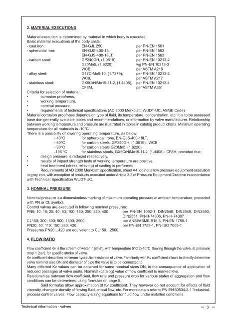
2. MATERIAL EXECUTIONS<br />
Material execution is determined by material in which body is executed.<br />
Basic material executions of the body casts:<br />
- cast iron: EN-GJL 250, per PN-EN 1561<br />
- spheroidal iron: EN-GJS-400-15, per PN-EN 1563<br />
EN-GJS-400-18LT, per PN-EN 1563<br />
- carbon steel: GP240GH, (1.0619), per PN-EN 10213-2<br />
G20Mn5, (1.6220) wg PN-EN 10213-3<br />
WCB,<br />
per ASTM A216<br />
- alloy steel: G17CrMo9-10, (1.7379), per PN-EN 10213-2<br />
WC9,<br />
per ASTM A217<br />
- stainless steel: GX5CrNiMo19-11-2, (1.4408), per PN-EN 10213-4<br />
CF8M,<br />
per ASTM A351<br />
Criteria for selection of material:<br />
• corrosion proofness,<br />
• working temperature,<br />
• nominal pressure,<br />
• requirements of technical specifications (AD 2000 Merkblatt, WUDT-UC, ASME Code)<br />
Material corrosion proofness depends on type of fluid, its temperature, concentration, etc. It is to be assessed<br />
base don generally available tables <strong>and</strong> recommendations, or information by valve manufacturer. Relationship<br />
between working temperature <strong>and</strong> pressure are illustrated in tables in catalog product charts. Minimum operating<br />
temperature for all materials is -10°C.<br />
There is a possibility of lowering operating temperature, as below:<br />
- 40°C for spheroidal irons, EN-GJS-400-18LT,<br />
- 60°C for carbon steels, GP240GH, (1.0619) i WCB,<br />
- 90°C for carbon steels G20Mn5, (1.6220),<br />
-196 °C for stainless steels, GX5CrNiMo19-11-2, (1.4408) i CF8M, provided that:<br />
• design pressure is reduced respectively,<br />
• results of impact strength tests at working temperature are positive,<br />
• <strong>heat</strong> treatment (stress relieving) of casting is performed.<br />
Requirements of AD 2000 Merkblatt specification, sheet A4, do not allow pressure equipment execution<br />
in grey iron, with exception of products executed under Article 3.3 of Pressure Equipment Directive in accordance<br />
with Technical Specification WUDT-UC.<br />
3. NOMINAL PRESSURE<br />
Nominal pressure is a dimensionless marking of maximum operating pressure at ambient temperature, preceded<br />
with PN or CL symbol.<br />
Control valves are executed in following nominal pressures:<br />
PN6; 10; 16; 25; 40; 63; 100; 160; 250; 320; 400<br />
per PN-EN 1092-1, DIN2548, DIN2549, DIN2550,<br />
DIN2551, PN-H-74306, PN-H-74307<br />
CL150; 300; 600; 900; 1500; 2500 per ANSI/ASME B16.5, PN-EN 1759-1<br />
PN20; 50; 110; 150; 260; 420 per PN-EN 1759-1, PN-ISO 7005-1<br />
Pressures PN20…420 are equivalent to CL150…2500.<br />
4. FLOW RATIO<br />
Flow coefficient Kv is the stream of water in [m 3 /h], with temperature 5°C to 40°C, flowing through the valve, at pressure<br />
drop 1 [bar], for specific stroke of valve.<br />
Kv coefficient describes minimum hydraulic resistance of valve. Familiarity with Kv coefficient allows to directly determine<br />
valve nominal size DN <strong>and</strong> diameter of pipe the valve is to be connected to.<br />
Many different Kv values can be obtained for same nominal sizes DN, in the consequence of application of<br />
reduced passages of valve seats. Nominal (catalog) value of flow coefficient is marked Kvs.<br />
Relationships between flow coefficient, flow rate <strong>and</strong> pressure drop for various states of aggregation <strong>and</strong> flow<br />
conditions can be determined using formulas on page 5.<br />
Said formulas allow approximation of Kv coefficient. They however do not account for effects of fluid<br />
viscosity, change in density of flowing fluid, critical flow, etc. For more details refer to PN-EN 60534-2-1 “Industrialprocess<br />
<strong>control</strong> valves. Flow capacity-sizing equations for fluid flow under installed conditions.<br />
Technical information - valves 3