- Page 1: www.polna.com.pl PRODUCTCATALOGUE A
- Page 6 and 7: Our Company Zakłady Automatyki POL
- Page 8 and 9: Download this questionnaire from: h
- Page 10 and 11: CONTENT TECHNICAL INFORMATION Page
- Page 12 and 13: PRODUCTS OF AUTOMATIC CONTROL ENGIN
- Page 14 and 15: 2. MATERIAL EXECUTIONS Material exe
- Page 16 and 17: Valve plugs with quick opening char
- Page 18 and 19: Among maintenance-free packings are
- Page 20 and 21: • position transmitter, • limit
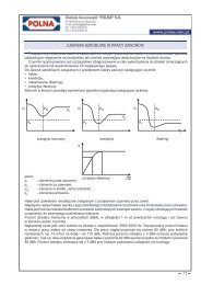
- Page 22 and 23: Harmful phenomena in the work of va
- Page 24 and 25: Fig. 4. Valve for compressible medi
- Page 26 and 27: NON-CATALOG PRODUCTION Zakłady Aut
- Page 28 and 29: 4. Products adapted to the specific
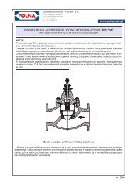
- Page 30 and 31: Steam reduction valve. An angular b
- Page 32 and 33: Minimum flow valve. Nominal size of
- Page 34 and 35: Deposit water valve. An anti-cavita
- Page 36 and 37: Anti-cavitation valve. This product
- Page 38 and 39: SINGLE-PORTED GLOBE CONTROL VALVES
- Page 40 and 41: Standard Extension Bellow seal Fig.
- Page 42 and 43: Table 4. Working parameters for spe
- Page 44 and 45: Table 5…11. Allowable working ove
- Page 46 and 47: Single-ported globe control valves
- Page 48 and 49: Table 15. Allowable pressure drops
- Page 50 and 51: Note: 1. In Table 16, theoretical a
- Page 52 and 53:
Standard bonnet valve with pneumati
- Page 54 and 55:
CONTROL VALVES TYPE Z ® WITH QUICK
- Page 56 and 57:
NOTE: In case of need for quick eme
- Page 58 and 59:
SINGLE-PORTED GLOBE CONTROL VALVES
- Page 60 and 61:
Fig. 1a. Valve Z1A - contoured valv
- Page 62 and 63:
Table 2. Part list with materials I
- Page 64 and 65:
Table 7. Material: WCB as per ASTM
- Page 66 and 67:
Table 11. Flow ratios Kvs. Kvs F Se
- Page 68 and 69:
NOISE REDUCTION: Should noise due t
- Page 70 and 71:
Table 16. Control valve length, fla
- Page 72 and 73:
Table 21: SW socket welding ends DN
- Page 74 and 75:
Table 25: Handwheels series 20 - ty
- Page 76 and 77:
SINGLE-PORTED GLOBE CONTROL VALVES
- Page 78 and 79:
Valve with multi-step plug Valves w
- Page 80 and 81:
DOUBLE-PORTED CONTROL VALVES TYPE Z
- Page 82 and 83:
Fig. 1a. Valve Z1B - unbalanced plu
- Page 84 and 85:
Table 2. Part list with materials I
- Page 86 and 87:
Table 7. Material: WCB as per ASTM
- Page 88 and 89:
Table 11: Flow ratios Kv s . F L =0
- Page 90 and 91:
NOISE REDUCTION: Should noise due t
- Page 92 and 93:
Table 15b: Control valves connectio
- Page 94 and 95:
Table 20: Dimensions of non-process
- Page 96 and 97:
Table 24: Sizes and weights of pneu
- Page 98 and 99:
CLASSIFICATION AND MARKING: - Z1B -
- Page 100 and 101:
SINGLE-PORTED GLOBE CONTROL VALVES
- Page 102 and 103:
Valve with three-step plug and thro
- Page 104 and 105:
SINGLE-PORTED GLOBE CONTROL VALVES
- Page 106 and 107:
Table 3…9. Allowable working over
- Page 108 and 109:
Table 10:Technical specification of
- Page 110 and 111:
CLASSIFICATION AND MARKING E - Z2 -
- Page 112 and 113:
DESIGN AND TECHNICAL SPECIFIACTION:
- Page 114 and 115:
Table 4…10. Allowable working ove
- Page 116 and 117:
where: H - stroke [mm] p 1 ÷ p 2 -
- Page 118 and 119:
CLASSIFICATION AND MARKING: - - 7 0
- Page 120 and 121:
Face-to-face dimensions: a) flanged
- Page 122 and 123:
Kv s FLOW RATIOS AND PRESSURE DROPS
- Page 124 and 125:
VALVE DRIVES Rotary pneumatic valve
- Page 126 and 127:
Pneumatic actuators, rotary piston
- Page 128 and 129:
EXTERNAL SIZES, END CONNECTION SIZE
- Page 130 and 131:
CLASSIFICATION AND MARKING: Z33 Act
- Page 132 and 133:
View W DIMENSIONS FOR ASSEMBLY WITH
- Page 134 and 135:
DOUBLE-PORTED CONTROL GLOBE VALVES
- Page 136 and 137:
Table 1. Type and options for bonne
- Page 138 and 139:
OVERALL DIMENSIONS, CONNECTIONS AND
- Page 140 and 141:
SINGLE-PORTED GLOBE CONTROL VALVES
- Page 142 and 143:
Table 3. Flow coefficients Kvs [m 3
- Page 144 and 145:
BUTTERFLY VALVES TYPE PRS APPLICATI
- Page 146 and 147:
Table 3. Dimensions and weights of
- Page 148 and 149:
DRIVES Various types of drive manua
- Page 150 and 151:
PRS-1 PRS-2 Fig. 8 Installation of
- Page 152 and 153:
PISTON DESUPERHEATERS TYPE ST-1 APP
- Page 154 and 155:
Table 2. Part list No Part name 1.
- Page 156 and 157:
MINIMUM FLOW VALVE TYPE ZM1 and Z1B
- Page 158 and 159:
MINIMUM FLOW VALVE TYPE Z1B-M APPLI
- Page 160 and 161:
DIAPHRAGM MULTI-SPRING PNEUMATIC AC
- Page 162 and 163:
DIMENSIONS AND WEIGHT Table 3. Dime
- Page 164 and 165:
DIAPHRAGM MULTI-SPRING PNEUMATIC AC
- Page 166 and 167:
HEAT ENGINEERING - TECHNICAL INFORM
- Page 168 and 169:
and 100·Q 2 Dp min. = Kvs 2 - for
- Page 170 and 171:
SELF-ACTUATING PRESSURE REDUCING RE
- Page 172 and 173:
INSTALLATION The regulator should b
- Page 174 and 175:
SELF-ACTUATING PRESSURE RELIEF REGU
- Page 176 and 177:
INSTALLATION The regulator should b
- Page 178 and 179:
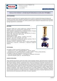
SELF-ACTUATING DIFFERENTIAL PRESSUR
- Page 180 and 181:
INSTALLATION Regulator is to be ins
- Page 182 and 183:
SELF-ACTUATING DIFFERENTIAL PRESSUR
- Page 184 and 185:
INSTALLATION Regulator is to be ins
- Page 186 and 187:
SELF-ACTUATING DIFFERENTIAL PRESSUR
- Page 188 and 189:
INSTALLATION: Regulator is to be in
- Page 190 and 191:
SELF-ACTUATING FLOW REGULATORS TYPE
- Page 192 and 193:
INSTALLATION Regulator is to be ins
- Page 194 and 195:
SELF-ACTUATING DIFFERENTIAL PRESSUR
- Page 196 and 197:
Internal springs - stainless spring
- Page 198 and 199:
SELF-ACTUATING PRESSURE REDUCING RE
- Page 200 and 201:
TECHNICAL SPECIFICATIONS DN 15 20 2
- Page 202 and 203:
SELF-ACTUATING DIFFERENTIAL PRESSUR
- Page 204 and 205:
TECHNICAL SPECIFICATIONS DN 15 20 2
- Page 206 and 207:
SELF-ACTUATING DIFFERENTIAL PRESSUR
- Page 208 and 209:
TECHNICAL SPECIFICATIONS DN 15 20 2
- Page 210 and 211:
SELF-ACTUATING DIFFERENTIAL PRESSUR
- Page 212 and 213:
TECHNICAL SPECIFICATIONS DN 15 20 2
- Page 214 and 215:
SELF-ACTUATING DIFFERENTIAL PRESSUR
- Page 216 and 217:
TECHNICAL SPECIFICATION DN 15 20 25
- Page 218 and 219:
SELF-ACTUATING DIFFERENTIAL PRESSUR
- Page 220 and 221:
TECHNICAL SPECIFICATIONS DN 15 20 2
- Page 222 and 223:
SELF-ACTUATING FLOW REGULATORS TYPE
- Page 224 and 225:
TECHNICAL SPECIFICATIONS DN 15 20 2
- Page 226 and 227:
APPLICATION AREA: SELF-ACTUATING DI
- Page 228 and 229:
TECHNICAL SPECIFICATIONS K VS 1) [m
- Page 230 and 231:
STRAINERS FOR HEATING SYSTEMS TYPE
- Page 232 and 233:
NEEDLE VALVES TYPE ZA APPLICATION A
- Page 234 and 235:
Inlet Outlet A B NPT 1/4” NPT 1/4
- Page 236 and 237:
Inlet Outlet A C E F NPT 1/4” NPT
- Page 238 and 239:
Inlet Outlet G 1/2” G 1/2” M20x
- Page 240 and 241:
MANIFOLD VALVES TYPE ZB APPLICATION
- Page 242 and 243:
Ventilation 4 4 holes hol. 4 4 hole
- Page 244 and 245:
NEEDLE VALVES, TYPE ZWD1 APPLICATIO
- Page 246 and 247:
NEEDLE VALVES, TYPE ZWZ 11 and ZWZ
- Page 249:
www.polna.com.pl chemicalindustry p