Automatic control and heat engineering - Polna S.A.
Automatic control and heat engineering - Polna S.A.
Automatic control and heat engineering - Polna S.A.

You also want an ePaper? Increase the reach of your titles
YUMPU automatically turns print PDFs into web optimized ePapers that Google loves.
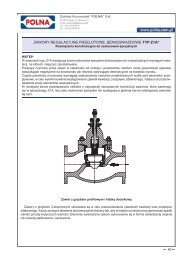
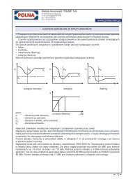
Fig. 4. Valve for compressible media to operate in noise<br />
<strong>and</strong> choked flow<br />
Fig. 5. Damage of valve due to<br />
cavitation<br />
Fig. 6. Damage of valve due to<br />
flashing<br />
Hydrodynamic noise is generated by flow of fluids, <strong>and</strong> its sources can be as follows:<br />
- turbulent flow interacting with valve <strong>and</strong> pipeline walls,<br />
- cavitation,<br />
- evaporation (flashing).<br />
Cavitation consists in local, usually in vena contracta area, evaporation of fluid due to pressure drop below<br />
evaporation pressure p v<br />
. Then, due to valve outlet pressure increase to value p 2<br />
> p v<br />
, implosion of generated<br />
steam bubbles occurs. In addition to noise, such a phenomenon features sudden accelerations <strong>and</strong> blows of<br />
two-phase mixture (fluid-steam), <strong>and</strong> resulting damages (Fig. 5) to valve or pipeline surfaces.<br />
Should outlet pressure stay lower than evaporation pressure (p 2<br />
< p v<br />
) fluid is permanently turned to mixture of<br />
fluid <strong>and</strong> steam, with steam share depending on pressure <strong>and</strong> temperature.<br />
This phenomenon is called evaporation (flashing).<br />
Then sudden increase in flow volume <strong>and</strong> speed occurs. Mixture stream erodes internal valve surfaces (Fig. 6) <strong>and</strong> pipeline,<br />
<strong>and</strong> is the source of noise as well. The most harmful phenomenon is however cavitation. Its effect can be reduced by means<br />
of application of proper materials <strong>and</strong> surface hardening technologies on one h<strong>and</strong>, <strong>and</strong> application of design methods for<br />
elimination or <strong>control</strong>ling of cavitation on the other h<strong>and</strong>.<br />
Another proven methods are: improving valve plug <strong>and</strong> valve seat durability by stelliting their phases or whole trims, diffusion<br />
or plasma nitriding, allowing achievement of surface hardness 950 HV to the depth of ca.0.1 mm, or through hot-setting<br />
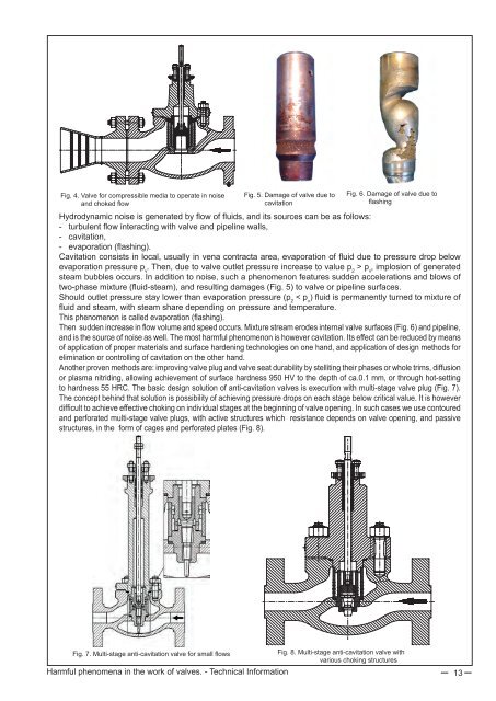
to hardness 55 HRC. The basic design solution of anti-cavitation valves is execution with multi-stage valve plug (Fig. 7).<br />
The concept behind that solution is possibility of achieving pressure drops on each stage below critical value. It is however<br />
difficult to achieve effective choking on individual stages at the beginning of valve opening. In such cases we use contoured<br />
<strong>and</strong> perforated multi-stage valve plugs, with active structures which resistance depends on valve opening, <strong>and</strong> passive<br />
structures, in the form of cages <strong>and</strong> perforated plates (Fig. 8).<br />
Fig. 7. Multi-stage anti-cavitation valve for small flows<br />
Fig. 8. Multi-stage anti-cavitation valve with<br />
various choking structures<br />
Harmful phenomena in the work of valves. - Technical Information 13