Automatic control and heat engineering - Polna S.A.
Automatic control and heat engineering - Polna S.A.
Automatic control and heat engineering - Polna S.A.

Create successful ePaper yourself
Turn your PDF publications into a flip-book with our unique Google optimized e-Paper software.
www.polna.com.pl<br />
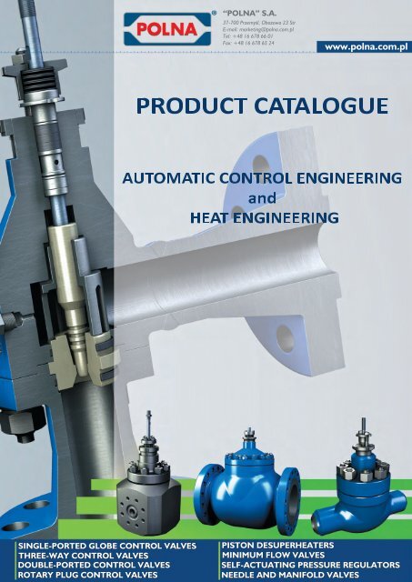
PRODUCTCATALOGUE<br />
AUTOMATICCONTROLENGINEERING<br />
<strong>and</strong><br />
HEATENGINEERING
„POLNA” S.A.<br />
23 Obozowa Street, 37-700 Przemyśl, POLAND<br />
Phone: +48 16 678 66 01<br />
Fax: +48 16 678 65 24<br />
+48 16 678 37 10<br />
website:<br />
www.polna.com.pl<br />
+48 16 678 66 01 extension / mobile phone<br />
The Board of Directors 200<br />
Sales <strong>and</strong> Marketing Director 379 / +48 693 920 446<br />
Marketing Department 248 / +48 533 301 083<br />
Export Department [offers <strong>and</strong> orders] 258 / +48 609 369 810<br />
Service 382 / +48 609 369 265<br />
+48 16 678 66 25<br />
Sales <strong>and</strong> Marketing Specialists<br />
Control valves, butterfly valves complete with electric <strong>and</strong> pneumatic<br />
acutators<br />
Self-actuating regulators, strainers,<br />
central lubrication equipment, water distillers<br />
E-mail addresses<br />
Offers 269; 389<br />
Orders realization 310<br />
312<br />
Marketing <strong>and</strong> Sales Department<br />
Offers [domestic]<br />
Export Department [offers <strong>and</strong> orders]<br />
Service<br />
Purchasing Department<br />
marketing@polna.com.pl<br />
oferty@polna.com.pl<br />
automatyka@polna.com.pl<br />
sales@polna.com.pl<br />
serwis@polna.com.pl<br />
zakupy@polna.com.pl
Dear Ladies <strong>and</strong> Gentlemen,<br />
we are proud to present you with POLNA’s great offer of a wide range of products<br />
from the automatic <strong>control</strong> <strong>engineering</strong> <strong>and</strong> <strong>heat</strong> <strong>engineering</strong> sectors, to central<br />
lubrication <strong>and</strong> laboratory equipment. We specialize in the designing <strong>and</strong><br />
manufacturing of <strong>control</strong> valves, steam desuper<strong>heat</strong>ers, needle valves, regulators,<br />
central lubrication equipment, distillers <strong>and</strong> re-distillers.<br />
We aim at fulfilling the Customer’s needs. Our traditions date back over<br />
80 years, which enhances the determination for constant improvement of our<br />
products, processes <strong>and</strong> everything that we do within our team <strong>and</strong> in the whole<br />
organization.<br />
It is our mission to ensure:<br />
• the highest quality <strong>and</strong> reliability of products for our Customers,<br />
• a stable increase of the company’s goodwill for our Shareholders,<br />
• the feeling of security <strong>and</strong> opportunities for development for our<br />
Employees,<br />
• business responsibility (protection of the natural environment <strong>and</strong> social<br />
interests).<br />
Designing <strong>and</strong> manufacture of individual products is based on complete realization<br />
of the technical assumptions agreed on with the Customer. We are constantly<br />
broadening our offer of non-catalog products, aimed at individual needs of our<br />
recipients.<br />
Kind regards<br />
Andrzej Piszcz<br />
The President of the Management Board,<br />
Executive Director
Our Company<br />
Zakłady Automatyki POLNA S.A. is a company with a long tradition. It has been producing industrial fittings<br />
since the end of the 1960s. Over the years, the range of manufactured products has been systematically<br />
broadened <strong>and</strong> the construction solutions used have been improved. The current trademark has been used<br />
since 1972 <strong>and</strong> products bearing that trademark are well known among domestic <strong>and</strong> foreign customers.<br />
Apart from st<strong>and</strong>ard catalogue products, POLNA specializes in special manufactures of valves adjusted<br />
to individual Customers’ requirements.<br />
Our customers include some of the leading companies from various branches of industry:<br />
o ALSTOM POWER – power industry<br />
o SYNTHOS DWORY– chemical industry<br />
o SIEMENS – automatic <strong>control</strong><br />
o Polish Oil & Gas Company (PGNiG) – gas industry<br />
o ORLEN – petrochemical industry<br />
o FOSTER WHEELER – power industry<br />
o AUSTRIAN ENERGY – power industry<br />
o SKODA POWER – power industry<br />
The quality of POLNA’s products is guaranteed by Quality Management System certificates it holds:<br />
- Quality Management System Certificate of Conformity with EN ISO 9001:2008 norm.<br />
- Quality Assurance System Certifi cate of Conformity with Directive 97/23/EC – Module H.<br />
- Quality Assurance System Certifi cate of Conformity with Directive 97/23/EC – Annex I, p.4.3.<br />
- We confirm compliance of <strong>control</strong> valves <strong>and</strong> actuators with ATEX Directive 94/9/EC.<br />
More information about the company, its certifi cates <strong>and</strong> its product offer can be found on our website:<br />
www.polna.com.pl.<br />
PRZEMYŚL- Think it over <strong>and</strong> come!<br />
Industrial values<br />
Przemyśl has got a direct connection with the transit route Wrocław –<br />
Kraków – Korczowa (A4 <strong>and</strong> Road no.4). The last section of the motorway<br />
from Kraków to the Ukrainian border (currently road no. 4), which 20 km<br />
before Przemyśl turns into the dual carriageway no. 77, leading to Medyka,<br />
is planned to be fi nished by 2012.<br />
The closest airport is located in Jasionka near Rzeszów (appr. 90 km from<br />
Przemyśl). The airport off ers national <strong>and</strong> international air connections<br />
(including cheap airlines).<br />
In industrial part of town is located PRZEMYŚL SUB-ZONE OF<br />
TARNOBRZEG SPECIAL ECONOMIC ZONE EURO-PARK WISŁOSAN<br />
(TSSE), www.tsse.pl.<br />
Przemyśl belongs to a select group of the oldest <strong>and</strong><br />
most beautiful Polish towns. A thous<strong>and</strong> years old,<br />
tempestuous history of the town has been inseparably<br />
intertwined with the history of the whole Republic of<br />
Pol<strong>and</strong>. It is located in the south-east corner of Pol<strong>and</strong>,<br />
in the eastern part of Podkarpackie Voivodeship <strong>and</strong> in<br />
the valley of the river San. Przemyśl, together with its<br />
surroundings, has many tourist, recreation <strong>and</strong> historical<br />
virtues. The town also constitutes an important transport<br />
interchange, connecting the East with the West <strong>and</strong> the<br />
North with the South of Europe. Besides, it plays an<br />
important role in transboundary cooperation with Ukraine.
Tourist values<br />
Welcome to Przemyśl! It is a beautiful <strong>and</strong> unique town. Mother nature herself took care of the picturesqueness<br />
nature of this part of the country, <strong>and</strong> its attractive location makes it possible to reach the Bieszczady highl<strong>and</strong>s,<br />
the tourist routes of Pogórze Przemyskie, as well as the great city of Lvov,<br />
situated less than 100 kilometres from Przemyśl. For many centuries<br />
communication routes between East with West <strong>and</strong> North with South<br />
have crossed here, thanks to which the town was formed, Walking along<br />
its narrow streets, you can touch ten centuries of the town’s history<br />
with numerous material traces, almost a thous<strong>and</strong> of which have been<br />
registered as construction <strong>and</strong> architectural monuments.<br />
Being situated at the meeting point of cultures <strong>and</strong> religions of the East<br />
<strong>and</strong> West has resulted in a national diversity <strong>and</strong> rich cultural heritage,<br />
developed by generations of Polish, Ukrainian <strong>and</strong> Jewish communities.<br />
The periods of the Polish partitions <strong>and</strong> the reign of the Austro-Hungarian monarchy contributed to the very<br />
special nature of the town.<br />
The Fortress of Przemyśl<br />
The strategic location of Przemyśl induced the Austrian<br />
authorities to commence a construction of a huge fortress in<br />
the 19th century that played a significant role during WWI.<br />
Its presence, attractiveness <strong>and</strong> fame directed the tourist<br />
development of the town under the promotional name “Tourist<br />
Town Przemyśl Fortress”. The town attracts many tourists <strong>and</strong><br />
lovers of fortifi cations with its ruins of massive forts <strong>and</strong> war<br />
cemeteries. Enthusiasts of militaria <strong>and</strong> fortifi cation mysteries<br />
will surely fi nd the bunkers of the Molotov Line attractive.<br />
Active <strong>and</strong> cultural tourism<br />
Przemyśl is one of the rare towns, in the centre of which you can sunbathe by the San River in the middle of<br />
summer <strong>and</strong> ski during winter down the 800-metre lit slope, equipped with ski-lift. Tourists, who appreciate the<br />
beauty of nature <strong>and</strong> l<strong>and</strong>scapes, are fascinated with history, multiple cultures<br />
<strong>and</strong> prefer active leisure will surely feel wonderful here.<br />
Natural sights, plenty of which can be found in Przemyśl <strong>and</strong> the Foothills,<br />
may be considered as combining ACTIVE AND CULTURAL tourism. The most<br />
valuable of these is Arboretum in Bolestraszyce (7 km from the town). Here you<br />
can see rare species of trees <strong>and</strong> bushes from all over the world. In the manor<br />
house dating back to the 19th century the Institute of Physical Geography was<br />
established.<br />
Castles, Cathedrals, Churches…<br />
The very location of Przemyśl, at the meeting point of cultures <strong>and</strong> religions,<br />
<strong>and</strong> their mutual inter-penetration, led to a unique effect in the form of abundant<br />
monuments of sacral, secular <strong>and</strong> military architecture, expressed in almost a<br />
thous<strong>and</strong> registered construction <strong>and</strong> architectural objects. The centre of the<br />
town is especially rich in historical buildings. The Casimir Castle dating back<br />
to the 14th century, with pallatium <strong>and</strong> rotunda of the turn of 10th <strong>and</strong> 11th<br />
centuries, remains of the fortifi ed walls, Reformati Monastery <strong>and</strong> Benedictine<br />
Nunnery with churches of 16th century, Franciscan <strong>and</strong> Carmelite monastery<br />
complexes from the Baroque period, as well as many bourgeois town houses.<br />
The Market Square <strong>and</strong> narrow streets are the most frequently visited places in<br />
the town The good condition of these historical objects, clear signs, numerous<br />
leaflets, folders <strong>and</strong> guides has made it possible to move freely in this attractive area of the town. The very centre<br />
of the Old Town has its own “underground town”. The majority of buildings have basements <strong>and</strong> underpasses,<br />
which are often interconnected.<br />
Tatar Mound (Kopiec Tatarski) <strong>and</strong> the „Zniesienie” citadel<br />
Unique mounds only found in the Małopolska region of Pol<strong>and</strong> – in Cracow <strong>and</strong>, particularly numerous, in<br />
Przemyśl area – will probably remain an archaeology mystery forever. The time of their creation is unknown;<br />
the Tatar Mound (Kopiec Tatarski) was a mystery as early as in the 16th century. The mound is worth visiting,<br />
since there is a wonderful view from this highest point in the area. Nearby, there are ruins of the citadel fort<br />
XVI “Zniesienie”. Even nowadays can we see steel rails here: the tracks on which huge mortars used to turn<br />
around.<br />
Przemyśl is a beautiful, interesting <strong>and</strong> unique place. It is worth coming to stay here.
Download this questionnaire from: http://www.polna.com.pl/en/catalogues-<strong>and</strong>-products.html
ZAKLADY AUTOMATYKI<br />
POLNA SA<br />
37-700 Przemysl, ul. Obozowa 23<br />
TECHNICAL SPECIFICATION FORM<br />
CONTROL VALVES<br />
Measurement point no.<br />
Manufacturer serial number<br />
User serial number<br />
1 Place of installation 57 Manufacturer Type<br />
2 Function 58 Pneumatic Diaphragm type Piston type .<br />
3 Explosion hazard zone 59 Operation Unilateral Bilateral .<br />
4 Ambient temperature min max 60 Size Membrane working area<br />
5 Allowed noise level 61 Stroke / rotation angle<br />
6 Pipeline identification no. 62 Supply pressure min max<br />
7 DN / PN Wall thickness mm 63 Input signal range<br />
TECHNICAL PARAMETERS TO BE CONSIDERED FOR VALVE SELECTION<br />
8 Pipeline material 64<br />
9 Pipeline insulation Thermal Acoustic 65 Air connection<br />
10 66 Other actuators electric hydraulic h<strong>and</strong> operated<br />
11 Pipeline connections 67<br />
12 Working medium 68 H<strong>and</strong>wheel Top Lateral<br />
13 Working medium at outlet fluid steam gas 69<br />
14 70 Manufacturer Type<br />
15 min norm max unit 71 Input signal pneumatic electric<br />
16 Flow 72 Valve open at<br />
17 Inlet pressure P1 73 Valve closed at<br />
18 Outlet pressure P2 74 Operation unilateral bilateral<br />
19 Temperature T1 75 Characteristics linear .<br />
20 Medium density at inlet P1 or M 76 Air connections<br />
21 Evaporation pressure Pv 77 Accessories by-pass manometers<br />
22 Critical pressure Pc 78 Explosion-proof execution spark-safe explosion safe<br />
23 Kinematic viscosity 79<br />
24 Specific <strong>heat</strong> y 80 Manufacturer Type<br />
25 Compressibility coefficient Z 81 Switch type mech. approx. pneum.<br />
26 82 Switch position closed % stroke open<br />
27 Pressure with valve closed P1 P2 83 Switch operation open close<br />
28 Supply air pressure min max 84 Explosion-proof execution spark-safe explosion-safe<br />
29 Valve status w/o supply open closed susp. 85<br />
ACTUATOR<br />
POSITION LEVER<br />
LIMIT SWITCHES<br />
30<br />
86 Manufacturer Type<br />
31 Max calculated flow ratio Kv 87 Valve type 2-way 3-way 4-way<br />
32 Min calculated flow ratio Kv 88 Valve supply failure status open closed susp.<br />
33 Selected catalogue Kv 89<br />
34<br />
Kv /NOISE<br />
Calculated noise level dB(A) 90 Air connection Connection size<br />
35 Manufacturer Type 91 Electric parameters V Hz W<br />
36 Body type 92 Explosion-proof execution spark-safe explosion-safe<br />
37 Flow direction 93<br />
38 Nominal pressure 94 Reducing valve Manufacturer Type<br />
39 Nominal sizes 95 with filter with manometer<br />
40 End connections flanged flangeless welding threaded 96 Location transmitter Manufacturer Type<br />
41 97<br />
42 Extended connections 98 Pneumatic booster Manufacturer Type<br />
43 Bonnet type st<strong>and</strong>ard extension bellow seal TA-Luft 99<br />
44 100 Blocking valve Manufacturer Type<br />
VALVE UNIT<br />
45 Body / bonnet material / 101<br />
46 Valve plug - valve seat unit st<strong>and</strong>ard silenced . 102 Pulse tubes material<br />
47 Characteristics linear equal percentage on/off 103<br />
48 Valve plug / valve plug stem material / 104 Attestations chemical <strong>and</strong> mechanical tests<br />
49 Guiding sleeve / valve seat material / 105 Other examinations<br />
50 106 Certificates body/bonnet bolts/nuts<br />
51 Valve seat type metallic soft 107 valve plug-valve seat unit<br />
52 Valve plug - valve seat unit hardening coating 108<br />
53 109<br />
54 Tightness class 110<br />
55 Packing PTFE graphite . 111<br />
56<br />
112<br />
Comments:<br />
SOLENOID VALVE<br />
ACCESSORIES<br />
SPECIAL REQUIREMENTS<br />
Design<br />
Fig. no.<br />
Item<br />
Offer request no.<br />
Change Date Name Change Date Signature Order no. Item no. No. of pcs.<br />
Download this questionnaire from: www.polna.com.pl
CONTENT<br />
TECHNICAL INFORMATION<br />
Page<br />
1. Products of automatic <strong>control</strong> <strong>engineering</strong> .................................................................................... 1<br />
2. Harmful phenomena in the work of valves. .................................................................................... 11<br />
3. Non-catalog production .............................................................................................................. 15<br />
AUTOMATIC CONTROL ENGINEERING PRODUCTS<br />
4. Single-ported globe <strong>control</strong> valves type Z .................................................................................... 27<br />
5. Control valve type Z with quick closure circuits for gases .......................................................... 43<br />
6. Single-ported globe <strong>control</strong> valves type Z1A .................................................................................... 47<br />
7. Control valves type Z1A - Design solutions for special applications ........................................... 65<br />
8. Single-ported cage <strong>control</strong> valves type Z1B .................................................................................... 69<br />
9. Control valves type Z1B - Design solutions for special applications ........................................... 89<br />
10. Single-ported globe <strong>control</strong> valves type Z2 .................................................................................... 93<br />
11. Three-way <strong>control</strong> valves type Z3 ................................................................................................. 100<br />
12. Rotary plug <strong>control</strong> valves type Z33 ................................................................................................. 108<br />
13. Rotary plug <strong>control</strong> valves type Z33 with piston <strong>and</strong> rotary actutation ............................................. 120<br />
14. Double-ported <strong>control</strong> valves type Z10 ................................................................................... 123<br />
15. Single-ported globe <strong>control</strong> valves type ZH ................................................................................... 129<br />
16. Butterfly valves type PRS .............................................................................................................. 133<br />
17. Piston desuper<strong>heat</strong>ers type ST-1 ................................................................................................. 141<br />
18. Minimum flow valve type ZM1 <strong>and</strong> Z1B-M ................................................................................... 145<br />
19. Diaphragm multi-spring pneumatic actuators type P/R .......................................................... 149<br />
20. Diaphragm multi-spring pneumatic actuators type P1/R1 .......................................................... 153<br />
HEAT ENGINEERING<br />
TECHNICAL INFORMATION<br />
21. Heat <strong>engineering</strong> products ............................................................................................................. 155<br />
HEAT ENGINEERING PRODUCTS<br />
22. Self-actuating pressure reducing regulators type ZSG 1 ......................................................... 159<br />
23. Self-actuating pressure relief type ZSG 3 ................................................................................... 163<br />
24. Self-actuating differential pressure reducing regulators type ZSG 5 ............................................ 167<br />
25. Self-actuating differential pressure reducing regulators with flow reduction type ZSG 6 ................ 171<br />
26. Self-actuating differential pressure relief regulators type ZSG 7 ............................................ 175<br />
27. Self-actuating flow regulators type ZSG 8 ................................................................................... 179<br />
28. Self-actuating differential pressure <strong>and</strong> flow regulators type ZSG 9 ............................................ 183<br />
29. Self-actuating pressure reducing regulators type ZSN 1 ......................................................... 187<br />
30. Self-actuating pressure reducing regulators type ZSN 2 ......................................................... 191<br />
Revision: CONTENT/06/2013<br />
Valid until the next revision
31. Self-actuating pressure relief regulators type ZSN 3 ...................................................................... 195<br />
32. Self-actuating differential pressure reducing regulators type ZSN 5 ............................................ 199<br />
33. Self-actuating differential pressure reducing regulators with flow reduction type ZSN 6 .................. 203<br />
34. Self-actuating differential pressure relief regulators type ZSN 7 ............................................ 207<br />
35. Self-actuating flow regulators type ZSN 8 ................................................................................... 211<br />
36. Self-actuating differential pressure <strong>and</strong> flow regulators type ZSN 91; 92 ............................... 215<br />
37. Strainers for <strong>heat</strong>ing systems type FS-1 .................................................................................... 219<br />
38. Needle valves type ZA ............................................................................................................. 221<br />
39. Manifold valves type ZB ............................................................................................................. 229<br />
40. Needle valves type ZWD 1 ............................................................................................................. 233<br />
41. Needle valves type ZWZ 11 ............................................................................................................. 237<br />
Page<br />
Revision: CONTENT/06/2013<br />
Valid until the next revision
PRODUCTS OF AUTOMATIC CONTROL ENGINEERING - TECHNICAL INFORMATION<br />
CONTENT<br />
Introduction ......................................................................................................................................<br />
Page<br />
1<br />
Design versions ............................................................................................................................... 2<br />
Material executions .......................................................................................................................... 3<br />
Nominal pressure ............................................................................................................................. 3<br />
Flow ratio ......................................................................................................................................... 4<br />
Flow characteristics ......................................................................................................................... 4<br />
Internal tightness ............................................................................................................................. 5<br />
Bonnet, types <strong>and</strong> packings ............................................................................................................. 6<br />
End connections, types .................................................................................................................... 7<br />
Hardening of valve internal parts ..................................................................................................... 7<br />
Drive selection ................................................................................................................................. 8<br />
Harmful effects in valve operation .................................................................................................... 9<br />
INTRODUCTION<br />
Fluid flow ratio regulation appliances, which keep the required regulation characteristics, are critical in industrial<br />
automatics systems. The main component of such appliances are <strong>control</strong>lers, which adjust the resistance for<br />
flowing fluid, <strong>and</strong> drives (actuators), which provide mechanic energy required in setting of <strong>control</strong>lers.<br />
The following are representatives of this group of appliances, manufactured by Zakłady Automatyki<br />
POLNA SA:<br />
• globe <strong>and</strong> angle <strong>control</strong> valves,<br />
• three-way <strong>control</strong> valves,<br />
• butterfly valves.<br />
Regarding the type of drive, <strong>control</strong>lers are manufactured in following executions:<br />
• with spring diaphragm pneumatic actuators,<br />
• with electric <strong>and</strong> electro-hydraulic actuators,<br />
• with pneumatic piston actuators,<br />
• with h<strong>and</strong> operated drive,<br />
• without drive.<br />
•<br />
Regarding the fact that valves are the largest group of <strong>control</strong>lers, the expression “valves” is hereinafter often<br />
interchangeable with expression “<strong>control</strong>lers”.<br />
While selecting valves for specific working conditions one should consider the following aspects:<br />
1. valve design version,<br />
2. material execution,<br />
3. nominal pressure,<br />
4. flow coefficient,<br />
5. flow characteristics,<br />
6. internal tightness,<br />
7. bonnet type <strong>and</strong> packing,<br />
8. body connection types,<br />
9. hardening of valve internal parts,<br />
10. selection of drive,<br />
11. harmful effects in valve operation.<br />
1
1. DESIGN VERSIONS<br />
The design version aspect applies only to valves.<br />
Valves can be subdivided using the following criteria:<br />
a) position of body inlet <strong>and</strong> outlet<br />
• globe,<br />
• three-way,<br />
• angle,<br />
b) closing component<br />
• with linear motion valve plug,<br />
• with rotary motion valve plug,<br />
c) shape of closing component<br />
• profile valve plug,<br />
• perforated valve plug,<br />
• multi-stage valve plug,<br />
• cage valve plug,<br />
d) balancing of axial forces<br />
• unbalanced,<br />
• balanced,<br />
e) reversibility of operation<br />
• reversible design double-ported valves,<br />
• irreversible design single-ported valves.<br />
Globe valves with linear situation of input <strong>and</strong> output are the basic, most common group of valves.<br />
Three-way valves are used in installations where mixing or separation of fluid is required. Angle valves are<br />
preferred option in applications where flashing (evaporation) <strong>and</strong> large pressure drops occur. A variation of<br />
angle valves are „ ” valves, with parallel but not axial body ends.<br />
Rotary plug globe valves are recommended in cases of large flows <strong>and</strong> dem<strong>and</strong> for precise adjustment<br />
in the beginning of opening. Perforated (perforated) components are used mostly to reduce noise emissions.<br />
Multi-stage valve plugs reduce cavitation <strong>and</strong> choked flow.<br />
In cage valves there is a piston valve plug, working with perforated <strong>control</strong> cage. They are used for<br />
large pressure drops applications.<br />
Pressure balancing of valve aims at equalization of static pressure on both sides of valve plug, by<br />
means of balance holes or internal valve plug (pilot).<br />
For selection of the valve balancing method the following factors must be taken into account:<br />
a) plug - pilot<br />
- flow direction - above the plug (Flow To Close - FTC),<br />
- high leakage class - (V class),<br />
- enhanced rangeability,<br />
- limited possibility to manufacture two-stage plugs to apply throttling cages.<br />
b) balancing <strong>and</strong> relieving holes in the plug<br />
- flow direction under the plug (Flow To Open - FTO), - max. leakage class (IV class),<br />
- plug sealing subjects to wearing - it must be replaceable, - possibility to manufacture multi-stage plugs<br />
to <strong>and</strong> apply throttling cages.<br />
Reversibility of valve operation denotes possibility of changing its function (pressing the valve plug stem can<br />
cause opening or closing of valve) in the consequence of different assembly of valve internal parts.<br />
While selecting valve design one should consider the following aspects:<br />
• leakage class<br />
Single-ported valves are more tight than double-ported ones.<br />
• balancing of axial forces<br />
Double-ported valves require smaller resetting forces <strong>and</strong> allow transferring of larger pressure drops than in<br />
the case of single-ported valves with same actuators.<br />
• flow coefficient<br />
Single-ported valves feature better possibility of flow reduction, whereas double-ported valves <strong>and</strong> rotary plug<br />
valves feature better flow coefficients than single-ported ones, with same valve diameter.<br />
• nominal pressure<br />
Irreversible valves are used in applications with higher nominal pressure than in the case of reversible valves.<br />
• fluid viscosity<br />
It is recommended, that single-ported valves are used with dense fluids, with viscosity v>10 -5 [m 2 /s], where<br />
laminar flow may be observed.<br />
2<br />
Technical information - valves
2. MATERIAL EXECUTIONS<br />
Material execution is determined by material in which body is executed.<br />
Basic material executions of the body casts:<br />
- cast iron: EN-GJL 250, per PN-EN 1561<br />
- spheroidal iron: EN-GJS-400-15, per PN-EN 1563<br />
EN-GJS-400-18LT, per PN-EN 1563<br />
- carbon steel: GP240GH, (1.0619), per PN-EN 10213-2<br />
G20Mn5, (1.6220) wg PN-EN 10213-3<br />
WCB,<br />
per ASTM A216<br />
- alloy steel: G17CrMo9-10, (1.7379), per PN-EN 10213-2<br />
WC9,<br />
per ASTM A217<br />
- stainless steel: GX5CrNiMo19-11-2, (1.4408), per PN-EN 10213-4<br />
CF8M,<br />
per ASTM A351<br />
Criteria for selection of material:<br />
• corrosion proofness,<br />
• working temperature,<br />
• nominal pressure,<br />
• requirements of technical specifications (AD 2000 Merkblatt, WUDT-UC, ASME Code)<br />
Material corrosion proofness depends on type of fluid, its temperature, concentration, etc. It is to be assessed<br />
base don generally available tables <strong>and</strong> recommendations, or information by valve manufacturer. Relationship<br />
between working temperature <strong>and</strong> pressure are illustrated in tables in catalog product charts. Minimum operating<br />
temperature for all materials is -10°C.<br />
There is a possibility of lowering operating temperature, as below:<br />
- 40°C for spheroidal irons, EN-GJS-400-18LT,<br />
- 60°C for carbon steels, GP240GH, (1.0619) i WCB,<br />
- 90°C for carbon steels G20Mn5, (1.6220),<br />
-196 °C for stainless steels, GX5CrNiMo19-11-2, (1.4408) i CF8M, provided that:<br />
• design pressure is reduced respectively,<br />
• results of impact strength tests at working temperature are positive,<br />
• <strong>heat</strong> treatment (stress relieving) of casting is performed.<br />
Requirements of AD 2000 Merkblatt specification, sheet A4, do not allow pressure equipment execution<br />
in grey iron, with exception of products executed under Article 3.3 of Pressure Equipment Directive in accordance<br />
with Technical Specification WUDT-UC.<br />
3. NOMINAL PRESSURE<br />
Nominal pressure is a dimensionless marking of maximum operating pressure at ambient temperature, preceded<br />
with PN or CL symbol.<br />
Control valves are executed in following nominal pressures:<br />
PN6; 10; 16; 25; 40; 63; 100; 160; 250; 320; 400<br />
per PN-EN 1092-1, DIN2548, DIN2549, DIN2550,<br />
DIN2551, PN-H-74306, PN-H-74307<br />
CL150; 300; 600; 900; 1500; 2500 per ANSI/ASME B16.5, PN-EN 1759-1<br />
PN20; 50; 110; 150; 260; 420 per PN-EN 1759-1, PN-ISO 7005-1<br />
Pressures PN20…420 are equivalent to CL150…2500.<br />
4. FLOW RATIO<br />
Flow coefficient Kv is the stream of water in [m 3 /h], with temperature 5°C to 40°C, flowing through the valve, at pressure<br />
drop 1 [bar], for specific stroke of valve.<br />
Kv coefficient describes minimum hydraulic resistance of valve. Familiarity with Kv coefficient allows to directly determine<br />
valve nominal size DN <strong>and</strong> diameter of pipe the valve is to be connected to.<br />
Many different Kv values can be obtained for same nominal sizes DN, in the consequence of application of<br />
reduced passages of valve seats. Nominal (catalog) value of flow coefficient is marked Kvs.<br />
Relationships between flow coefficient, flow rate <strong>and</strong> pressure drop for various states of aggregation <strong>and</strong> flow<br />
conditions can be determined using formulas on page 5.<br />
Said formulas allow approximation of Kv coefficient. They however do not account for effects of fluid<br />
viscosity, change in density of flowing fluid, critical flow, etc. For more details refer to PN-EN 60534-2-1 “Industrialprocess<br />
<strong>control</strong> valves. Flow capacity-sizing equations for fluid flow under installed conditions.<br />
Technical information - valves 3
It is advised that DIVENT valve calculation <strong>and</strong> calculation program is used, which can be downloaded from<br />
the following website<br />
www.polna.com.pl<br />
To ensure correct work of automatic <strong>control</strong>s <strong>and</strong> to avoid oversizing of the valve, adopted catalog<br />
value of flow coefficient is to be higher than calculated. It is assumed that maximum value of calculated flow<br />
coefficient is to be achieved within the 70…90% range of valve plug stroke.<br />
5. FLOW CHARACTERISTIC<br />
Valve flow characteristics is the relation between flow value <strong>and</strong> closing component stroke. Regarding pressure<br />
drop we can divide characteristics into internal <strong>and</strong> working characteristics.<br />
Internal characteristics describes relation between relative flow coefficient “kv” <strong>and</strong> relative stroke “h” at<br />
constant pressure drop in valve, where:<br />
Working characteristic describes change in flow in function of stroke at variable pressure drop in valve, in<br />
installation conditions.<br />
Valves have the following flow characteristics:<br />
• linear - „L”<br />
• equal percentage - „P”<br />
• modified - „M”<br />
• quick opening - „S”<br />
Valve characteristic is obtained by proper design of fluid flow area between valve choking components regarding<br />
the stroke. This function is realized through contoured valve plugs or perforated components (perforated valve<br />
plugs, <strong>control</strong> cages):<br />
- linear characteristic: equal increase in relative stroke “h” correspond with equal increase in relative flow<br />
coefficient “kv”.<br />
where: k<br />
v0<br />
is a minimum <strong>control</strong>led relative flow ratio,<br />
m - characteristic inclination<br />
For POLNA valves: = 0,02; m = 1<br />
- equal percentage characteristic: equal increase in relative stroke “h” corresponds with equal per cent increase<br />
in relative flow coefficient „kv”<br />
where: n is characteristic inclination drawn in semi-logarithmic coordinates (h, lg kv).<br />
- modified characteristic: is a characteristics in between “L” <strong>and</strong> “P”, created for individual needs <strong>and</strong> specific<br />
installations. It mostly is of equal percentage nature at the beginning of stroke (h=0…0.3) <strong>and</strong> linear in the<br />
subsequent part of stroke.<br />
- quick opening characteristic: used for “open-close” on-off operation; it allows achievement of nominal flow at<br />
low stroke (h=0.6…0.7) <strong>and</strong> increase in flow coefficient by ca. 20% regarding catalog value, at full stroke.<br />
Selection between value with equal percentage <strong>and</strong> linear characteristics depends on requirements<br />
concerning changes in flow rate <strong>and</strong> pressure on valve.<br />
With small changes in flow rate during valve operation, up to 50%, selection of characteristics has no material<br />
effect to performance of <strong>control</strong> system. However for valves operating at large changes in flow rate, with<br />
variable pressure drop, <strong>and</strong> in case of doubt selection of constant per cent characteristics is recommended.<br />
Valves with linear characteristics are recommended for systems, where pressure drop on valve is<br />
independent from flow rate, e.g. <strong>control</strong> of fluid level.<br />
4<br />
Technical information - valves
Valve plugs with quick opening characteristics are designated exclusively for on-off operation. Limitations in<br />
application of perforated components are due to their susceptibility to contaminants suspended in fluids, hence<br />
the need for their permanent filtering.<br />
Kv [m 3 /h] - flow coefficient (calculated)<br />
Q [m 3 /h] - fluid flow volume intensity<br />
Q N<br />
[Nm 3 /h] - gas flow volume intensity in normal conditions (0°C, 760 mm Hg)<br />
G [kg/h] - flow mass intensity<br />
p 1<br />
[bar(a)] - absolute pressure upstream valve<br />
p 2<br />
[bar(a)] - absolute pressure downstream valve<br />
Δp [bar] - pressure drop on valve (available pressure drop)<br />
ρ 1<br />
[kg/m 3 ] - fluid density upstream valve<br />
ρ N<br />
[kg/m 3 ] - fluid density in normal conditions<br />
T 1<br />
[K] - fluid temperature before agent<br />
v 2<br />
[m 3 /kg] - specific volume of steam for parameters p 2<br />
<strong>and</strong> T 1<br />
v [m 3 /kg] - specific volume of steam for parameters (p 1<br />
/2) <strong>and</strong> T 1<br />
1,0<br />
Flow characteristic<br />
Butterfly valve flow characteristics<br />
kv<br />
0,9<br />
0,8<br />
0,7<br />
0,6<br />
0,5<br />
0,4<br />
0,3<br />
0,2<br />
quick opening<br />
linear<br />
equal percentage<br />
kv<br />
1<br />
0,9<br />
0,8<br />
0,7<br />
0,6<br />
0,5<br />
0,4<br />
0,3<br />
0,2<br />
0,1<br />
0,1<br />
0,0<br />
0,0 0,1 0,2 0,3 0,4 0,5 0,6 0,7 0,8 0,9 1,0<br />
h<br />
Fig. 1. Flow characteristics for valves<br />
0<br />
0 10 20 30 40 50 60 70 80 90<br />
Fig. 2. Flow characteristics for butterfly valves<br />
a<br />
α o<br />
Three way <strong>and</strong> rotary valve plug valves feature linear characteristics, whereas butterfly valves feature<br />
characteristics similar to equal percentage characteristics in the range of opening angles 0°…60° (Fig. 2).<br />
6. INTERNAL TIGHTNESS<br />
Maximum leakage of closure by valve choking components (“plug - seat”) is described in leakage classes as<br />
per PN-EN 60534-4.<br />
Leakage class Allowed leakage<br />
II - 5 • 10 -3 Kvs<br />
IV - 10 -4 Kvs<br />
Technical information - valves 5
V - 3 • 10 -4 • Dp•D [cm 3 /min]<br />
VI - 1 [blister/min] do D = 25<br />
Allowable leakage<br />
[blister / min.]<br />
Seat diameter<br />
D [mm]<br />
Allowable leakage<br />
[bubble / min.]<br />
Seat diameter<br />
D [mm]<br />
1 25 6 80<br />
2 40 11 100<br />
3 50 27 150<br />
4 65 45 200<br />
Checking the internal tightness is carried out as part of acceptance tests of the product with the use of<br />
air with pressure 3…4 [bar] (for valves in classes II, IV <strong>and</strong> VI) <strong>and</strong> with water with working pressure conforming<br />
to the order (for valves in class V).<br />
Valves in class VI have seats (single-seat valves) or plugs (two-seat valves) equipped with packing<br />
rings made of PTFE reinforced with glass fibre.<br />
Because of durability of the packing material, pressure drop on the valve must not exceed 35 bar.<br />
Valves in class V require careful <strong>and</strong> laborious fitting of closing elements <strong>and</strong> a greater disposition force<br />
of the drive.<br />
Another acceptance criterion is the norm PN-EN 12266-1 “Industrial valves. Testing of metallic valves.<br />
Part 1: Pressure tests, test procedures <strong>and</strong> acceptance criteria. M<strong>and</strong>atory requirements.”<br />
The following can be used as test media:<br />
• Air (for pressure 6 bar),<br />
• Water (for pressures 1,1 • Dp max.<br />
).<br />
Acceptable leakage [mm 3 /s] can be calculated for the given class according to the following formulas:<br />
Medium Class A Class B Class C Class D Class E Class F Class G<br />
Water 0 0,01 • D 0,03 • D 0,1 • D 0,3 • D 1,0 • D 2,0 • D<br />
Air 0 0,3 • D 3,0 • D 30 • D 300 • D 3000 • D 6000 • D<br />
where: Dp [bar] - working pressure drop<br />
D [mm] - valve seat diameter<br />
Internal tightness is checked during acceptance tests, using air at pressure 3…4 [bar] for valves of<br />
class II, IV, VI, <strong>and</strong> using water at working pressure as per order, for valves of class V.<br />
Class VI valves valve seats (single-ported valves) or valve plugs (double-ported valves) are equipped<br />
with PTFE seal ring reinforced with glass fiber. Due to durability of sealing material pressure drop on valve<br />
cannot exceed 35 bar.<br />
Class V valves require precise <strong>and</strong> time-consuming fitting of valve closing components <strong>and</strong> higher<br />
available force of drive.<br />
7. BONNETS, TYPES AND PACKINGS<br />
Bonnet is a pressure equipment used to contain <strong>and</strong> seal the component (valve plug stem, shaft) transmitting<br />
motion from drive to closing component.<br />
Bonnet can be integral part of body or be separated from body.<br />
Control valves are fitted with following types of bonnets:<br />
- st<strong>and</strong>ard bonnet<br />
- extension bonnet<br />
- bellow seal bonnet<br />
The basic criterion in selection of bonnet is fluid temperature. Extension bonnets are used in both high <strong>and</strong> low<br />
temperatures. There is a execution of extension bonnet specially designed for cryogenics (temperatures up to<br />
-196°C).<br />
Bellow seal bonnets ensure absolute internal tightness <strong>and</strong> they are used mostly for aggressive media.<br />
St<strong>and</strong>ard bellow seal bonnets can be used up to pressure 35 bar. Application for higher pressures require to use<br />
multi-layer bellows.<br />
Cast iron valves are only fitted with st<strong>and</strong>ard bonnet. Control valves DN150…250, PN160…CL2500 can<br />
be equipped with self-sealing bonnets. Type of valve plug stem packing in bonnet depends on temperature <strong>and</strong><br />
type of fluid. In majority of cases PTFE rings with graphite are applied. Pure graphite packing is recommended<br />
for steam <strong>and</strong> high temperature operations. Such packing does not require lubrication, although they do require<br />
adjustment during operation, due to relaxation <strong>and</strong> wearing-off.<br />
6<br />
Technical information - valves
Among maintenance-free packings are PTFE-V <strong>and</strong> TA Luft packings. PTFE-V ones are executed in PTFE<br />
in the form of V-profile rings, pressed to sealed surfaces with spiral spring. TA Luft packing comprises two<br />
kits of seal rings loaded with package of disk springs, <strong>and</strong> compliant in terms of tightness requirements of<br />
TA Luft:2002, Clause 5.2.6.4, <strong>and</strong> VDI 2440:2000.<br />
8. END CONNECTIONS, TYPES<br />
Body connections are used to connect valve to pipeline <strong>and</strong> they should provide tightness, pressure<br />
resistance, vibration resistance <strong>and</strong> pipeline deformations.<br />
Valves are executed with following types of connections:<br />
• flanged,<br />
• flangeless,<br />
• welding.<br />
Flanged connections are executed as per European (PN-EN 1092-1, PN-EN 1092-2, PN-EN 1759-1,<br />
DIN 2548, DIN 2549, DIN 2550, DIN 2551, PN-ISO 7005-1, PN-H-74306, PN-H-74307) <strong>and</strong> American<br />
(ANSI/ASME B16.5) st<strong>and</strong>ards.<br />
Regarding sealing surface type flanges can be executed with:<br />
• raised face type B1, B2, B, RF<br />
• groove, type D, D1, GF, DL<br />
• recess type F, F1, FF<br />
• ring-joint, type J, RTJ<br />
Rotary plug valves <strong>and</strong> butterfly valves have flangeless connections of S<strong>and</strong>wich type. Body is fitted between<br />
pipeline counter-flanges by means of bolted ends.<br />
Valves with welding connections are designed for butt welding, BW type, or socket welding, SW type. Pipe<br />
dimensions <strong>and</strong> body lengths specified in catalog apply to execution of connections from body casting.<br />
Application of smaller pipe dimensions is limited due to minimum internal diameter of pipe that can be achieved<br />
from casting (D1 min). In such case reduction stub is to be welded to body, which shall cause elongation<br />
of valve body by 100 mm (DN15…50), 150 mm (DN80, 100), 200 mm (DN150) <strong>and</strong> 300 mm (DN200, 250)<br />
– in case of stubs fixed on both sides of the valve.<br />
9. HARDENING OF VALVE INTERNAL PARTS<br />
In st<strong>and</strong>ard execution valve internal parts: valve plugs, valve seats, valve plug stems,<br />
cages, guiding sleeves are executed in high-alloy austenitic steel X6CrNiMoTi 17-12-2 (1.4571)<br />
as per PN-EN 10088-1.<br />
In order to improve mechanical <strong>and</strong> chemical resistance to fluid the following hardening methods<br />
of internal parts are used: stelliting, nitriding, <strong>heat</strong> treatment, protective coatings.<br />
Stelliting hardens the surface down to ca. 1 mm, to hardness of ca. 40 HRC. Stelliting can be applied to sealing<br />
phases of valve plug <strong>and</strong> valve seat, or additionally valve plug trim surfaces, openings of valve seats <strong>and</strong><br />
guiding sleeves, valve plug stem friction surfaces.<br />
Plugs with the diameter smaller than 10mm can be made of solid stellite.<br />
Nitriding (CrN) consists in hardening of component surfaces down to ca. 0.1 mm, to hardness of ca.<br />
900HV, in the effect of plasma or diffusion processes. Nitriding is recommended for application with surfaces<br />
exposed to friction or erosion. Heat treatment is applied in order to achieve high durability <strong>and</strong> resistance to<br />
wear. Depending on the material type hardness achieved is up to 45 HRC (1.4057) or 55 HRC (1.4125).<br />
Composite protecting coatings (BELZONA) are applied on body internal surfaces in order to protect them from<br />
erosion (flashing, abrasive fluids).<br />
Hardening of valve internal parts is recommended in the following cases:<br />
• h<strong>and</strong>ling of erosive fluids,<br />
• wet gas or saturated steam,<br />
• dry, pure gas<br />
(Dp> 25 bar (up to DN100), Dp> 12 bar (DN>100)),<br />
• chocked flow,<br />
• initial cavitation: (liquid Dp> 10 bar, temp. > 315°C).<br />
Contraindications for stelliting<br />
• boiler water pre-treated with hydrazine,<br />
• perforated components,<br />
Technical information - valves 7
10. SELECTION OF DRIVE<br />
Valves <strong>and</strong> butterfly valves can be equipped with spring diaphragm pneumatic actuator, piston actuator,<br />
electric actuator, electro-hydraulic actuator, h<strong>and</strong>whell, or no drive at all.<br />
Equipment without drives can be completed by end user with other types of actuators, such as springless<br />
diaphragm pneumatic, piston pneumatic acutator, crank actuator, <strong>and</strong> others, provided that such actuators are<br />
adapted to connection with valve bonnet <strong>and</strong> valve plug stem.<br />
H<strong>and</strong> operated equipment is mostly used for applications requiring on-off regulation.<br />
While selecting spring diaphragm pneumatic actuator the following is to be determined:<br />
• actuator type,<br />
• actuator size,<br />
• spring range,<br />
• supply pressure,<br />
• stroke,<br />
• requirements concerning accessories.<br />
Selection of pneumatic actuator (whether direct or reverse action) depends on equipment operation <strong>control</strong><br />
signal failure. Whether the valve is to stay open or closed on <strong>control</strong> signal failure is the technical requirement of<br />
installation.<br />
Actuator size, spring range <strong>and</strong> supply pressure are to be taken from tables in catalog, depending on required<br />
available force of actuator.<br />
Available force of actuator is to be lower than Fs calculated using the below formula:<br />
F s<br />
= 0,785 • 10 -4 • Dp • D 2 + F d<br />
where: F s<br />
[kN] - available force<br />
Dp [bar] - pressure drop on closed valve<br />
D [mm] - valve seat diameter<br />
F d<br />
[kN] - tightening force<br />
Values D <strong>and</strong> Fd are to be taken from catalog charts, <strong>and</strong> Δp from order.<br />
Disposition force of type „P” actuators - F SP<br />
[kN] is dependent on the active flank of the actuator A [cm 2 ], supply<br />
pressure p Z<br />
[kPa] <strong>and</strong> the final spring travel p 2<br />
[kPa].<br />
F SP<br />
=10 -4 • A • (p Z<br />
-p 2<br />
)<br />
Disposition force of type “R” actuators – F SR<br />
[kN] is dependent on the active flank of the actuator A [cm 2 ]<br />
<strong>and</strong> the initial spring travel p 1<br />
[kPa].<br />
F SR<br />
=10 -4 • A • p 1<br />
Disposition forces F SP<br />
<strong>and</strong> F SR<br />
calculated that way are established without consideration of friction force<br />
of movable elements (spindle of the actuator <strong>and</strong> the valve) or tolerances of spring manufactures, hence they<br />
should be treated with a 20% reserve regarding those factors.<br />
The calculations refer to single-seat valves type Z, Z1A <strong>and</strong> Z1B in a closed position.<br />
Catalog charts provide allowable pressure drops for various pneumatic actuators <strong>and</strong> various internal leakage<br />
classes of valves.<br />
Those values apply to single-ported valves, unbalanced, with fluid fed under the valve plug (FTO).<br />
With fluid fed above the valve plug (FTC) allowable pressure drop may be higher, however such an<br />
arrangement causes valve plug hitting the valve seat when closing <strong>and</strong> disturbances to <strong>control</strong>. Hence it is used<br />
mostly in on-off operations, with actuator equipped with higher stiffness springs. For valves with valve plug<br />
unbalanced it is assumed that available force Fs is at least equal to tightening force for class V leakage.<br />
In the case of double-ported valves it is not possible to procure a table of allowable pressure drops, due<br />
to dynamic forces occurring, which depend on i.a. actual flow conditions (pressure, fluid type, valve plug type,<br />
valve operation type). In case when knowledge of forces acting on double-ported valve plug stem is required,<br />
please contact manufacturer, stating all the data related to valve operation.<br />
Pneumatic actuator accessories may comprise the following:<br />
• top-mounted or side-mounted h<strong>and</strong>wheel,<br />
• positioner: pneumatic, electro-pneumatic with analog or digital signal (smart positioner),<br />
• air set,<br />
• three-way solenoid valve,<br />
8<br />
Technical information - valves
• position transmitter,<br />
• limit switches,<br />
• lock-up valve,<br />
• volume booster,<br />
• quick exhaust valve.<br />
H<strong>and</strong>wheel is applied in case of <strong>control</strong> signal failure, as well as to limit valve stroke.<br />
Application of positioners is recommended in following cases:<br />
• for systems requiring large pressure drops on valve,<br />
• for high working pressure,<br />
• for valves of nominal diameter DN > 100 mm,<br />
• for distance between valve <strong>and</strong> reducing valve exceeding 50 m,<br />
• for three-way valves,<br />
• for systems requiring high-speed action,<br />
• for viscous or highly contaminated fluids sedimenting on valve seat,<br />
• for media of temperature higher than 250°C or lower than -20°C,<br />
• when spring range does not correspond with range of out signal from <strong>control</strong>ler.<br />
Designation of accessories:<br />
- filter reductor is used to reduce supplying pressure to required value <strong>and</strong> to clean incoming air.<br />
- solenoid valve assists remote switching of <strong>control</strong> circuit on <strong>and</strong> off.<br />
- position transmitter is used to reflect position of valve plug stem in the form of unified pneumatic<br />
(e.g. 20…100 kPa) or electric (e.g. 4…20 mA) signal.<br />
- limit switches are used to signal preset positions of actuator stem.<br />
- lock-up valve is used to block valve plug stem movement in current position with <strong>control</strong> signal<br />
missing.<br />
- volume booster is used to accelerate actuator time of action.<br />
- quick drain valve allows to reduce actuator chamber drainage time.<br />
11. HARMFUL EFFECTS IN VALVE OPERATION<br />
Harmful effects in valve operation, such as noise, cavitation, choked flow, flashing, are discussed in the study<br />
titled „Harmful phenomena in the work of valves”.<br />
Technical information - valves 9
NOTES:<br />
10<br />
Revision: INF/03/2011<br />
Valid until the next revision.
Harmful phenomena in the work of valves. - TECHNICAL INFORMATION<br />
The flow of medium through the valve (depending on the kind <strong>and</strong> parameters of the medium) may cause<br />
phenomena having a negative impact on the environment <strong>and</strong> be destructive to the product’s durability.<br />
Risk factors should be diagnosed in detail in order to be used for actions aimed at limiting or eliminating their<br />
negative influence.<br />
Harmful phenomena connected with the flow include the following factors:<br />
• Noise<br />
• Cavitation<br />
• Evaporating (flashing)<br />
• Choked flow<br />
The conditions in which the above-mentioned phenomena occur are explained by the following graphs:<br />
p 1<br />
p VC p 2<br />
p V<br />
normall flow cavitation flashing<br />
where:<br />
p 1<br />
p 2<br />
p vc<br />
p v<br />
choked flow<br />
- pressure before the valve,<br />
- pressure after the valve,<br />
- pressure in the “vena contracta” zone,<br />
- pressure of evaporating.<br />
Dp √<br />
Medium flowing through valve shall invariably cause noise.<br />
Adverse effect of noise is due to its harmful effect to health <strong>and</strong> working environment. Noise is also the symptom<br />
of processes inside the valve, generally reducing durability of appliance, including damage.<br />
Noise level is measured in [dBA] units, 1 m from the pipeline surface <strong>and</strong> valve axis, in the direction to medium<br />
outlet.<br />
Human ear is most sensitive to frequencies 3000 to 4000 Hz. Allowable workplace noise level depends on<br />
duration of exposure. For continuous work it is 85 dB(A), for short exposures, say 15 minutes a day, it is up<br />
to 115 dB(A). 3 dB(A) difference means double increase in noise level; hence two appliances generating 82<br />
dB(A) are equivalent to one appliance generating 85 dB(A). Noise level drops by 3 dB(A) with each doubling<br />
of distance from pipeline.<br />
11
Sources of valve noise emissions may be as follows:<br />
- mechanic noise,<br />
- aerodynamic noise,<br />
- hydrodynamic noise.<br />
Mechanic noise may be caused by vibrations of valve internal parts, resonance, misguiding of moving parts,<br />
excessive clearance. One of the methods to eliminate such noise is application of cage construction <strong>and</strong> selection<br />
of proper clearances to valve working conditions.<br />
Fig. 1. Valve for high pressure <strong>and</strong> high temperature operation<br />
In Fig. 1 a valve is shown designated for operation at temperatures up to 500°C, with possibility of thermal<br />
shocks. Valve plug is guided in valve seat <strong>and</strong> in cage. Application of steel spring ring allows increase of<br />
clearance between valve plug <strong>and</strong> cage without causing vibrations <strong>and</strong> loss of tightness. Mechanic vibrations<br />
can also be reduced through change in valve plug weight <strong>and</strong> direction of medium flow.<br />
Aerodynamic noise is generated when mechanic energy of compressible medium flow is transformed to acoustic<br />
energy. Source of noise is increase in flow speed due to medium decompression, often exceeding speed of<br />
sound.<br />
Noise reduction can be achieved by means of using proper installation (insulation on outlet pipeline, increased<br />
thickness of pipeline walls), or by means of selecting proper valve construction. The most important <strong>and</strong> most<br />
efficient way is to apply in valve perforated <strong>control</strong> structures in the form of perforated valve plugs (Fig. 2) or cages<br />
(Fig. 3).<br />
Fig. 2. Perforated valve plug<br />
Fig. 3. Perforated <strong>control</strong> cages<br />
Splitting of a single stream to multitude of smaller, well adjusted streams, causes reduction in noise emission<br />
as high as by 10 dB(A), due to following:<br />
- reduction in efficiency of mechanic to acoustic energy transformation,<br />
- smaller spin causes generation of higher frequency energy, which is easier to damp by walls <strong>and</strong><br />
insulation,<br />
- high frequency sound (> 10 000 Hz) is less harmful to human ears.<br />
Another way of reducing aerodynamic noise (by ca. 5 dBA) is reduction in medium outflow speed at outlet.<br />
The most common method of doing so is increasing the outlet pressure by application of choking structures<br />
in the form of perforated cages <strong>and</strong> plates, <strong>and</strong> application of diffusers. In cases of high noise level it is often<br />
necessary to apply all those solutions at the same time (Fig. 4).<br />
12<br />
Harmful phenomena in the work of valves. - Technical Information
Fig. 4. Valve for compressible media to operate in noise<br />
<strong>and</strong> choked flow<br />
Fig. 5. Damage of valve due to<br />
cavitation<br />
Fig. 6. Damage of valve due to<br />
flashing<br />
Hydrodynamic noise is generated by flow of fluids, <strong>and</strong> its sources can be as follows:<br />
- turbulent flow interacting with valve <strong>and</strong> pipeline walls,<br />
- cavitation,<br />
- evaporation (flashing).<br />
Cavitation consists in local, usually in vena contracta area, evaporation of fluid due to pressure drop below<br />
evaporation pressure p v<br />
. Then, due to valve outlet pressure increase to value p 2<br />
> p v<br />
, implosion of generated<br />
steam bubbles occurs. In addition to noise, such a phenomenon features sudden accelerations <strong>and</strong> blows of<br />
two-phase mixture (fluid-steam), <strong>and</strong> resulting damages (Fig. 5) to valve or pipeline surfaces.<br />
Should outlet pressure stay lower than evaporation pressure (p 2<br />
< p v<br />
) fluid is permanently turned to mixture of<br />
fluid <strong>and</strong> steam, with steam share depending on pressure <strong>and</strong> temperature.<br />
This phenomenon is called evaporation (flashing).<br />
Then sudden increase in flow volume <strong>and</strong> speed occurs. Mixture stream erodes internal valve surfaces (Fig. 6) <strong>and</strong> pipeline,<br />
<strong>and</strong> is the source of noise as well. The most harmful phenomenon is however cavitation. Its effect can be reduced by means<br />
of application of proper materials <strong>and</strong> surface hardening technologies on one h<strong>and</strong>, <strong>and</strong> application of design methods for<br />
elimination or <strong>control</strong>ling of cavitation on the other h<strong>and</strong>.<br />
Another proven methods are: improving valve plug <strong>and</strong> valve seat durability by stelliting their phases or whole trims, diffusion<br />
or plasma nitriding, allowing achievement of surface hardness 950 HV to the depth of ca.0.1 mm, or through hot-setting<br />
to hardness 55 HRC. The basic design solution of anti-cavitation valves is execution with multi-stage valve plug (Fig. 7).<br />
The concept behind that solution is possibility of achieving pressure drops on each stage below critical value. It is however<br />
difficult to achieve effective choking on individual stages at the beginning of valve opening. In such cases we use contoured<br />
<strong>and</strong> perforated multi-stage valve plugs, with active structures which resistance depends on valve opening, <strong>and</strong> passive<br />
structures, in the form of cages <strong>and</strong> perforated plates (Fig. 8).<br />
Fig. 7. Multi-stage anti-cavitation valve for small flows<br />
Fig. 8. Multi-stage anti-cavitation valve with<br />
various choking structures<br />
Harmful phenomena in the work of valves. - Technical Information 13
Fig. 9. Rotary valve for operation In flashing<br />
conditions<br />
Fig. 10. Angle valve with anti-erosion seating<br />
Fig. 11. Valve fitted with protective cage<br />
Although occurrence of flashing depends only on flow parameters, <strong>and</strong> cannot be eliminated through design changes,<br />
its damaging effects can - <strong>and</strong> have to – be eliminated.<br />
In addition to above discussed methods of improving durability of valve components, POLNA offers also<br />
application of hardening coatings on internal valve body surfaces, <strong>and</strong> application of valves fitted with<br />
anti-corrosion bushing (Fig. 9); angle valves (Fig. 10); <strong>and</strong> valves with protective cage (Fig. 11).<br />
All above noise reduction methods applied in <strong>control</strong> valves by Zakłady Automatyki POLNA SA in Przemysl, are<br />
tailored to Customers’ needs.<br />
We design our valves after thorough analysis of phenomena occurring in flow process, based on detailed data <strong>and</strong><br />
using specialized computer software DiVent <strong>and</strong> CONVAL ® . Not only do our designs meet all st<strong>and</strong>ards, but also they<br />
solve problems the Customer’s are unaware of.<br />
CONVAL ® software has a Polish version, made by our own company, <strong>and</strong> contains data about the POLNA product<br />
offer.<br />
14<br />
Revision: HARMFUL EFFECTS./03/2011<br />
Valid until the next revision.
NON-CATALOG PRODUCTION<br />
Zakłady Automatyki “POLNA” S.A. in Przemyśl have been operating non-stop since 1899.<br />
Since 1960s, nineteen sixties, its many production programs can be divided into four product groups:<br />
• automatic <strong>control</strong> <strong>engineering</strong> (industrial automation)<br />
• <strong>heat</strong> <strong>engineering</strong><br />
• central lubrication equipment <strong>and</strong> systems<br />
• laboratory equipment: water distillers.<br />
The biggest product group consists of automatic <strong>control</strong> <strong>engineering</strong> products.<br />
This production started in 1967, when a licence for <strong>control</strong> valves <strong>and</strong> pneumatic actuators was purchased<br />
from MASONEILAN company – one of the world leaders in this industry.<br />
In subsequent years work continued on post-license works developing <strong>and</strong> exp<strong>and</strong>ing the range of <strong>and</strong><br />
varieties of products, as well as developing its own designs for the needs <strong>and</strong> requirements of the market.<br />
Such work led to the creation of a big offer of valves <strong>and</strong> pneumatic actuators within the Company’s<br />
catalog. The product range consists of valves ranging in size from DN15 up to 300 <strong>and</strong> with nominal pressure<br />
from PN6 – 400 <strong>and</strong> with flow coefficients from Kvs 0,01- 6,300 <strong>and</strong> with cast bodies made from various<br />
materials:<br />
• globe valves, passage, single-port valves with linear motion of the plug:<br />
Types Z, Z1A, Z1B, Z2,<br />
• globe valves, passage, double-port valves with linear motion of the plug:<br />
Type Z10,<br />
• globe valves, passage, single-port, with rotary-plug:<br />
Type Z33,<br />
• globe valves three-way valves with linear motion of the plug:<br />
Type Z3,<br />
• tight butterfly valves, lined:<br />
Type PRS,<br />
• diaphragm, pneumatic, multi-spring actuators:<br />
Type P/R, P1/R1, P5/R5.<br />
15
Over the last tens years, the importance of non-catalog products has increased, as they are designed<br />
<strong>and</strong> too the the requirements of the client <strong>and</strong> the technological needs of their project.<br />
At present, the share of the automatic <strong>control</strong> <strong>engineering</strong> products now exceeds 30% of production, thus the<br />
necessity of presenting them in more detail.<br />
1. Valves constructed using forged elements.<br />
The use of forgings in pressure elements of valves enables the use of this product to work in the<br />
highest burdens in terms of pressure, temperature <strong>and</strong> the corrosive environment, which is only achieved<br />
thanks to the proper selection of materials <strong>and</strong> construction solutions.<br />
Depending on the needs, we manufacture valves with various construction solutions: angle, passage,<br />
passage/angle („ ” shaped with parallel, non-axial ends) <strong>and</strong> three way valves.<br />
POLNA also offers a whole range of connections for pipelines; flange ( made to EN <strong>and</strong> ANSI st<strong>and</strong>ards)<br />
for BW welding, direct for the body, flange-less <strong>and</strong> others.<br />
The material used for the body is chosen depends on the working pressure during maximum working<br />
temperature. The most commonly used materials are:<br />
• S355J2G3 (1.0570),<br />
• 13CrMo4-5 (1.7335),<br />
• 14MoV6-3 (1.7715),<br />
• X10CrMoVNb9-1 (1.4903) ) <strong>and</strong> others.<br />
2. The Elimination or restriction of harmful effects related to flow.<br />
The flow of substances through a valve, depending on it’s type <strong>and</strong> parameters can cause such phenomena<br />
as high noise, cavitation, evaporation (flashing), choked flow <strong>and</strong> erosion levels, that could have a negative impact<br />
on the environment, reducing the regulatory values of the valve <strong>and</strong> having a negative impact on the product’s<br />
durability.<br />
To avoid such an impact these factors should be analyzed in detail. These actions are mainly focused<br />
on restricting the speed flow <strong>and</strong> the division of total pressure reduction on the valve into a few steps, so that the<br />
pressure reductions do not exceed critical levels.<br />
Multihole elements (plugs, cages, plates), are in common use, <strong>and</strong> their main role being to limit noise<br />
levels. The division of pressure is achieved by means of resistance structures within the valve, such as multistage<br />
plugs, cages <strong>and</strong> throttling plates.<br />
Reduction of flow speed is achieved by division of pressure reduction on the valve <strong>and</strong>/or application<br />
of enlarged outflow diameter in the valve’s body or exp<strong>and</strong>ing elements (diffusers).<br />
An important role is played by the proper choice of materials <strong>and</strong> the ways of increasing hardness of<br />
internal valve elements. We often utilize hardened surfaces using stelliting, plasma or diffusion nitriding, <strong>heat</strong><br />
enhancing <strong>and</strong> protective coating.<br />
All these factors will only fulfill their role if work conditions are known, valves are constructed properly<br />
with the skills <strong>and</strong> knowledge of our long experience.<br />
The opinions of POLNA product users prove that we can design <strong>and</strong> manufacture valves completely<br />
fulfilling even the very highest of their requirements.<br />
3. Valves designed for work in aggressive or dangerous environments.<br />
POLNA produces valves for work with dangerous substances such as oxygen, hydrogen, natural gas,<br />
acidic gases containing H 2<br />
S <strong>and</strong> in dangerous environments where there are risks of explosions.<br />
The preparation consists of the careful cleaning of surfaces coming into contact with the substance<br />
using both mechanical <strong>and</strong> chemical means, as well as using materials <strong>and</strong> ways of production <strong>and</strong> <strong>control</strong><br />
complying with safety regulations.<br />
Products intended for work in atmospheres with high risk of explosion are manufactured in compliance with<br />
the ATEX directive.<br />
16 SPECIAL VALVES
4. Products adapted to the specifics of particular industries.<br />
Every branch of industry has its own characteristics, which have to be taken into consideration in the<br />
phase of designing, manufacture <strong>and</strong> <strong>control</strong> of automatic <strong>control</strong> <strong>engineering</strong>.<br />
For products designed for power industry, the possibility of the occurrence of high temperature <strong>and</strong><br />
pressure, thermal shocks, choked flows <strong>and</strong> excess noise must be taken into consideration.<br />
POLNA has some tried <strong>and</strong> tested applications of product especially designed for various uses in power<br />
industry, such as:<br />
• boiler feed valves, also fulfilling the role of starting valves,<br />
• reducing <strong>and</strong> cooling stations with integrated injection in a pressure reducing valve,<br />
• elements of reducing <strong>and</strong> cooling stations with integrated steam pressure reducing valves,<br />
desuper<strong>heat</strong>ers, injection valves.<br />
Pressure reducing valves, passage <strong>and</strong> angle models, with balanced plugs, eliminating choked flow, with<br />
a vast range of flow regulation.<br />
Piston, ring, lance <strong>and</strong> steam-atomizing desuper<strong>heat</strong>ers.<br />
Anti-cavitation injection valves.<br />
• minimum flow valves used as pump by-pass valves,<br />
• condensate piling valves<br />
• three-way valves for power industry applications.<br />
For products designed for the gas <strong>and</strong> petrochemical industry, chemical resistance, it is important to take<br />
account of resistance to high pressures, flow speeds <strong>and</strong> significant temperature changes, as well as protection<br />
of the environment <strong>and</strong> work safety.<br />
Products include:<br />
• pressure reducing valves for significant changes of flow values,<br />
• valves eliminating choked flow <strong>and</strong> limiting noise,<br />
• valves working in low temperature environments (e.g. in Siberia),<br />
• deposit water valves,<br />
• high-pressure natural gas valves,<br />
• valves used in cryogenics,<br />
• anti-cavitation valves <strong>and</strong> valves resistant to erosion (flashing) for gas mines, stamping presses <strong>and</strong><br />
gas distribution plants.<br />
5. Valves complying with boiler regulations.<br />
Basic valve products refer to production in accordance with the 93/27/EC pressure directive , concerning<br />
the fixing on pipelines.<br />
POLNA also has the capability of manufacturing valves designed for vessels, in accordance with<br />
PL-EN 12952-3:2004 norm (“Water-tub boilers <strong>and</strong> auxiliary installations – Part 3: Design <strong>and</strong> calculation<br />
for pressure parts”) .<br />
6. Custom built valves manufactured to the clients requirements.<br />
POLNA has the capability to design <strong>and</strong> manufacture valves adjusted especially for particular uses.<br />
Detailed description of requirements is key. With the use of a professional computer program CONVAL<br />
we determine phenomena occurring in particular points of a valve’s work. That information, together with longst<strong>and</strong>ing<br />
experience, enables us to design valves fulfilling the recipient’s requirements. To mention just a few<br />
examples showing the variety of manufactures, we have made:<br />
- valves for underground installations, with a proper solution of valve’s drive,<br />
- high-pressure <strong>control</strong> <strong>and</strong> cut-off valves for the food industry,<br />
- a wide range of valves adjusted to work in conditions of cavitation risk. The structures of valves take into<br />
consideration the requirements concerning changes of flow values (regulatability) <strong>and</strong> reduction of pressure on<br />
the valve occurring at the change of valve’s opening. Due to the uniquity of those conditions, each valve may<br />
have a structure different from the others in terms of details of technical solution.<br />
SPECIAL VALVES<br />
17
Boiler feed valve, also fulfilling the role of a starting valve.<br />
A cast body, material G17CrMo9-10 (1.7379), with a self-tightening bonnet. The main plug is <strong>control</strong>led<br />
by an auxiliary plug (pilot), flow over the plug (FTC). A multi-step pilot allows to regulate small flows at big<br />
pressure reductions without the risk of cavitation occurring.<br />
The main plug: two-step up to the middle of lift, with resistance elements (plates). When opened wider,<br />
no internal throttling; the function of filling the boiler is carried out at a small pressure reduced. A protective<br />
cage on the seat. It is highly air-tight<br />
Reducing <strong>and</strong> cooling station.<br />
An angle steam power reduction valve DN25 / DN150, is made of X10CrMoVNb9-1 (1.4903). A multistage<br />
plug <strong>and</strong> resistance plates on the outflow aiming at elimination of choked flow <strong>and</strong> limiting the noise<br />
levels. The cooling chamber is an integral part of the valve. A lance desuper<strong>heat</strong>er, an injection valve with an<br />
anti-cavitation structure.<br />
STEAM<br />
WATER<br />
18 SPECIAL VALVES
Steam reduction valve.<br />
An angular body made of 13CrMo4-5 (1.7335). A self-tightening bonnet. The main plug: cage type,<br />
<strong>control</strong>led by an auxiliary plug (pilot). A diffuser integral with the body of the valve with three resistance<br />
plates.<br />
Piston desuper<strong>heat</strong>er<br />
Regulation scope Kvmax 10; regulatability 1:40, V class tightness in accordance with PN-EN 60534-4<br />
st<strong>and</strong>ards. The valve part with a one- or two-step profile plug made of the 13CrMo4-5 (1.7335).<br />
The pipeline diameter ranges to over DN200.<br />
WATER<br />
STEAM<br />
SPECIAL VALVES<br />
19
Ring desuper<strong>heat</strong>er.<br />
Regulation scope Kvmax 1.0; regulatability 1:3. Range of pipeline diameters: up to DN150.<br />
WATER<br />
STEAM<br />
Lance desuper<strong>heat</strong>er.<br />
Regulation scope Kvmax 1.0; regulatability 1:3. Range of pipeline diameters: up to DN300.<br />
WATER<br />
WATER<br />
STEAM<br />
STEAM<br />
Steam-atomizing desuper<strong>heat</strong>er.<br />
Feeding with auxiliary steam is necessary. Regulatability 1:15. Range of pipeline diameters: over DN150.<br />
ATOMIZING STEAM<br />
ATOMIZING STEAM<br />
WATER<br />
WATER<br />
20 SPECIAL VALVES
Minimum flow valve.<br />
Nominal size of the valve: DN50 PN320. It’s used for flow regulation approx. 60t/h at pressure reduction<br />
of up to 200 bar. Non-bonnet design with a packing seal in the low pressure zone.<br />
A three-step plug combined with a multi-hole sleeve creates six steps of throttling. Perfect closure<br />
tightness as a result of flow over the poppet (FTC). Adjusted to on-off function <strong>and</strong> <strong>control</strong> one, used in by-pass<br />
systems of feeding pumps.<br />
Condensate piling valve.<br />
It is fixed directly at the container with the outflow directed to the liquid surface, which eliminates<br />
potential destruction of the vessel’s elements by cavitation <strong>and</strong> erosion.<br />
surface of the water in the VESSEL<br />
Lustro wody w zbiorniku<br />
SPECIAL VALVES<br />
21
Valve with a two-step plug <strong>and</strong> a throttling cage with several throttling chambers.<br />
It is designed for applications reducing noise level <strong>and</strong> eliminating cavitation or choked flow.<br />
Control valve for low environment temperatures.<br />
DN300, CL600 valve works on natural gas installations in Siberia. A balanced plug, casts elements of<br />
the valve <strong>and</strong> an actuator made of cast steel are capable of working in low temperatures are available in the<br />
ASTM A352LC2 variety. The elastomer parts of the actuator (diaphragm, seals) are made of silicone.<br />
22 SPECIAL VALVES
Deposit water valve.<br />
An anti-cavitation structure with three multi-hole resistance plates.<br />
Natural gas valve.<br />
An angular body, pipeline counter flanges directly connected to the body. Working pressure 450 bar,<br />
nominal pressure PN700. Flow under the plug (FTO); full opening of the plug cuts off access of the agent <strong>and</strong><br />
impact of pressure on valve stem packing.<br />
SPECIAL VALVES<br />
23
Anti-cavitation valve.<br />
The body is made of a forging, threaded ends. A multi-step plug, <strong>and</strong> a throttling cage. Non-service<br />
packing of stem fulfilling tightness requirements according to TA Luft. It is currently in use at the “Dębno” gas<br />
mine in Pol<strong>and</strong>.<br />
Cut-off valve.<br />
A flange body is made of forged X2CrNiMo17-12-2 (1.4404) – 316L. material Working pressure is up<br />
to 530 bar. Two-part plug structure: an internal plug <strong>and</strong> a main plug for static relief upon the opening of the<br />
valve.. Flow over the plug (FTC), high closure tightness. This product has been designed especially for the<br />
food industry.<br />
24 SPECIAL VALVES
Anti-cavitation valve.<br />
This product solves the problem of regulation <strong>and</strong> anti-cavitation protection at small opening of the<br />
valve. The internal plug – multi-step, the main plug – two-step, with a throttling cage in the seat. Flow over the<br />
plug (FTC).<br />
Double-position anti-cavitation valve.<br />
This product solves the problem of small flows during big pressure reductions <strong>and</strong> big flows at small<br />
pressure reductions, if there is a risk of cavitation in both cases. A three-step profile/piston plug, a throttling<br />
cage divided into chambers with proper throttling.<br />
SPECIAL VALVES<br />
25
Valves for work in underground installations.<br />
Such valves require leading the drive over ground <strong>and</strong> connecting it to the valve in a durable <strong>and</strong><br />
reliable way. The length of distance elements <strong>and</strong> the way of fixing them to the ground must be chosen with<br />
considering the possibilities of the valve’s localization.<br />
High parameters <strong>control</strong> valve.<br />
The body is made of forged elements with structure „ ” DN250 PN320, Kvs320P. The material used is<br />
13CrMo4-5 (1.7335), a self-tightening bonnet, a plug balanced by a graphite ring. Manufacture conforming to<br />
PN-EN 12952 3:2004 “Water-tub boilers”.<br />
26 Revision: SPECIAL VALVES/03/2011<br />
Valid until the next revision.
SINGLE-PORTED GLOBE CONTROL VALVES TYPE Z ® 27<br />
APPLICATIONS:<br />
Single-ported globe <strong>control</strong> valves type Z ® are used in automatic <strong>and</strong> remote <strong>control</strong> systems to <strong>control</strong> flow of<br />
gases <strong>and</strong> liquids. Wide range of material <strong>and</strong> design versions make the valves widely sought-after in chemical<br />
industry, <strong>heat</strong> <strong>and</strong> power generation industry, paper industry, food industry, metallurgy <strong>and</strong> coal mining (versions<br />
for Western Europe market is marked: BR11).<br />
CHARACTERISTICS:<br />
• range of nominal sizes from DN15 to DN250 for<br />
pressure values PN10 to CL300,<br />
• various materials of valve body cast <strong>and</strong> internal<br />
parts, adapted to specific working conditions,<br />
• wide range of flow ratios <strong>and</strong> <strong>control</strong><br />
characteristics,<br />
• reduction in aggressive <strong>and</strong> toxic media<br />
emissions to environment through application<br />
o f b e l l o w s e a l b o n n e t s o r b o n n e t p a c k i n g s<br />
meeting requirements of TA - LUFT,<br />
• easy assembly <strong>and</strong> dismantling of<br />
v a l v e i n t e r n a l p a r t s f o r m a i n t e n a n c e<br />
<strong>and</strong> service,<br />
• high durability <strong>and</strong> reliability due to application<br />
of top-class materials <strong>and</strong> surface improvement<br />
processes (burnishing, stelliting, <strong>heat</strong> treatment,<br />
CrN coatings),<br />
• possibility of mating with reversible<br />
a c t i o n P / R ( c o l u m n ) m u l t i - s p r i n g a c t u a t o r s a n d c h a n g i n g t h e s p r i n g r a n g e w i t h n o e x t r a p a r t s ( k e e p i n g<br />
the number of springs),<br />
• possibility of fitting actuators with top drive,<br />
• possibility of performing diagnostics of “valve-actuator” system due to application of smart electro-pneumatic<br />
positioners,<br />
• high tightness of closure due to application of soft valve seats (with PTFE seals in the whole range of<br />
flows <strong>and</strong> characteristics, for valve plugs, balanced <strong>and</strong> unbalanced,<br />
• same flow ratios <strong>and</strong> <strong>control</strong> characteristics for “hard” valve seats (metal-to-metal) <strong>and</strong> “soft” valve seats<br />
(metal-gasket), for valve plugs, balanced <strong>and</strong> unbalanced,<br />
• reliable actuator-stem <strong>and</strong> valve seat-body connections,<br />
• small guiding sleeve <strong>control</strong> forces due to application of balanced valve plugs in valves DN40…250,<br />
• top-class flat <strong>and</strong> bonnet packings,<br />
• wide range of electric actuators,<br />
• possibility of mating with NN type h<strong>and</strong> operated drives,<br />
• possibility of special executions for oxygen, hydrogen, gas fuels, low temperature mediums (liquid oxygen,<br />
liquid nitrogen), acid gases containing H 2<br />
S; explosive atmospheres as per 94/9/EC - ATEX,<br />
• competitive prices – due to simple <strong>and</strong> functional design of valves <strong>and</strong> actuators <strong>and</strong> applied materials,<br />
• design <strong>and</strong> production process meets the requirements of Quality Management System ISO 9001 <strong>and</strong><br />
Directive 97/23/EC, <strong>and</strong> regulations of AD2000 Merkblatt, designated for installation on pipelines,<br />
Z ® is a trademark registered with Republic of Pol<strong>and</strong> Patent Office.
DESIGN AND TECHNICAL SPECIFICATION:<br />
Body (1): single-ported, flanged, cast in cast iron or cast steel.<br />
Nominal sizes: DN15; 20; 25; 32; 40; 50; 65; 80; 100; 125* ) ; 150; 200; 250<br />
* ) special execution, technical data according to individual inquiries.<br />
Nominal pressure: PN10; 16; 25; 40 (as per PN-EN 1092-1:2010 <strong>and</strong> PN-EN 1092-2:1999);<br />
CL150; CL300 (as per PN-EN 1759-1:2005).<br />
Steel flanges CL150; CL300 are so designed that they can be assembled with flanges executed per American<br />
st<strong>and</strong>ards ANSI/ASME B16.5 <strong>and</strong> MSS SP44. In American st<strong>and</strong>ards flanges are identified with nominal values<br />
in “Classes”, to which nominal pressure (PN) values as per PN-ISO 7005-1:2002 correspond.<br />
Equivalent identification as per PN are: CL150: PN 20 <strong>and</strong> CL300: PN 50.<br />
Table 1. Flanged end connections<br />
Facing of flange types<br />
Material<br />
Nominal pressure Raised face Groove Recess Ring - joint<br />
Identification<br />
Grey iron PN10; 16<br />
- - -<br />
PN10; 16; 25; 40 B 2) D F -<br />
Spheroidal iron PN10; 16; 25; 40 - - -<br />
Cast steel<br />
CL150 - -<br />
CL300 DL ( D1 1 ) F ( F1)<br />
J (RTJ)<br />
1<br />
) - only for CL300; 2 ) - B1 – (Ra=12.5 mm, concentric surface structure “C”), B2 – (Ra as agreed with the customer);<br />
() - identification of connections as per ASME B16.5<br />
Possible execution of flanges per specification <strong>and</strong> indicated st<strong>and</strong>ards<br />
Face-to-face dimensions: as per PN-EN 60534-3-1; 2000r. - Fig. no. 7 ; Table 19 <strong>and</strong> 20. Series 1 - for PN10;<br />
16; 25; 40; series 37- for CL150; series 38 - for CL300<br />
Bonnet (2) - non-cast - assembled to body via assembly plate (DN15-100)<br />
- cast (DN150-250): a) st<strong>and</strong>ard, b) extension (for cast steel valves),<br />
c) bellows (for cast steel valves).<br />
St<strong>and</strong>ard Extension Bellow seal<br />
DN15…50<br />
DN65…100<br />
TA LUFT packing (all types)<br />
Fig. 1. Bonnets DN15…100<br />
28<br />
Single-ported globe <strong>control</strong> valves type Z
St<strong>and</strong>ard Extension Bellow seal<br />
Fig. 1a. Bonnets DN125…250<br />
Valve plug (3) - contoured, balanced, unbalanced<br />
• <strong>control</strong> characteristics: - linear (L)<br />
- equal percentage (P)<br />
- quick-opening (S)<br />
• rangeability: - 50:1<br />
Kvs 0,01…1<br />
DN15…50<br />
Kvs 0,01…16 (DM/DW)<br />
DN15…50<br />
Unbalanced valve plugs<br />
Kvs 25…160<br />
DN40…100<br />
Kvs 63…630<br />
DN125…250<br />
Kvs 25…160<br />
DN40…100<br />
Balanced valve plugs<br />
Kvs 250…630<br />
DN125…250<br />
Fig. 2. Valve plugs<br />
Single-ported globe <strong>control</strong> valves type Z 29
Valve seat (4) - screwed in, with centering cone, sealing <strong>and</strong> preventing unscrewing:<br />
• hard version,<br />
• soft version (PTFE packing).<br />
Valve plug stem (5) - burnished or quenched <strong>and</strong> tempered, polished sealing contact surface<br />
Drain plug (6) - steel or stainless steel: allows cleaning of body interior (delivered separately)<br />
Body gasket (7) - asbestos-free:<br />
• flat – aramid <strong>and</strong> hardened graphite (1.4571); in metallic casing (1.4571), multiple edges<br />
• bonnet: - packings formed in various materials (PTFE-V; PTFE+graphite;<br />
expan ded graphite; braided graphite);<br />
- with TA Luft compression springs (PTFE-V; graphite)<br />
Table 2. Packing types with application ranges.<br />
Packing<br />
PTFE-V<br />
PTFE + Graphite<br />
PTFE-V / TA-LUFT<br />
Graphite<br />
Graphite / TA-LUFT<br />
PN / CL<br />
PN10…CL300<br />
Temperature [°C]<br />
Bonnet<br />
St<strong>and</strong>ard Extension Bellow<br />
-46...+200<br />
-198...-46<br />
+200...+300<br />
-100...+200<br />
+200...+300 +300...+450 +200...+400<br />
Leakage class: - basic: Class IV as per PN-EN 60534-4 - hard valve seat<br />
- bubble-tight Class VI as per PN-EN 60534-4 - soft valve seat<br />
Table 3. Listing of components with materials<br />
Item Component Materials<br />
1 Body<br />
EN-GJL 250 EN-GJS 400-18 LT GP 240 GH<br />
GX5CrNiMo 19-11-2<br />
WCB<br />
(EN-JL 1040) (EN-JS 1025) (1.0619)<br />
(1.4408)<br />
CF8M<br />
DN15…100 S 355 J2G3 (1.0570) X6CrNiMoTi 17-12-2 (1.4571)<br />
2 Bonnet<br />
EN-GJL 250 EN-GJS 400-18 LT GP 240 GH<br />
GX5CrNiMo 19-11-2<br />
DN125…250<br />
WCB<br />
(EN-JL 1040) (EN-JS 1025) (1.0619)<br />
(1.4408)<br />
CF8M<br />
3 Plug<br />
X6CrNiMoTi 17-12-2; (1.4571)<br />
X6CrNiMoTi 17-12-2; (1.4571) + stellite + CrN<br />
X17CrNi 16-2 ; (1.4057) + <strong>heat</strong> treatment<br />
4 Seat<br />
X6CrNiMoTi 17-12-2; (1.4571)<br />
X6CrNiMoTi 17-12-2; (1.4571) + stellite<br />
X6CrNiMoTi 17-12-2; (1.4571) + PTFE<br />
X17CrNi 16-2; (1.4057) + <strong>heat</strong> treatment<br />
5 Stem<br />
X6CrNiMoTi 17-12-2; (1.4571)<br />
X6CrNiMoTi 17-12-2; (1.4571) + stellite + CrN<br />
X17CrNi 16-2 ; (1.4057) + <strong>heat</strong> treatment<br />
6 Drain plug S 355 J2G3 (1.0570) X6CrNiMoTi 17-12-2; (1.4571)<br />
7 Body gasket<br />
in metal casing X6CrNiMoTi 17-12-2 (1.4571) ; NOVATEC PREMIUM;<br />
SIGRAFLEX HOCHDRUCK; MWK-50 SPETOMET<br />
8 Guiding sleeve<br />
X6CrNiMoTi 17-12-2; (1.4571) + CrN<br />
X6CrNiMoTi 17-12-2; (1.4571) + stellite + CrN<br />
X17CrNi 16-2 ; (1.4057) + <strong>heat</strong> treatment<br />
9 Compression plate C45 (1.0503); X30Cr13 (1.4028); X6CrNiMoTi 17-12-2; (1.4571)<br />
10 Bolt 8.8 A4 - 70<br />
11 Nut 8 A4 - 70<br />
12 Packing PTFE + GRAFIT; PTFE - „V”; GRAPHITE<br />
13 Spring 12R10 (SANDVIK)<br />
14 O-ring Fluorine rubber (FKM)<br />
15 Guiding sleeve<br />
X6CrNiMoTi 17-12-2; (1.4571) + CrN<br />
X6CrNiMoTi 17-12-2; (1.4571) + stellite + CrN<br />
X17CrNi 16-2 ; (1.4057) + <strong>heat</strong> treatment<br />
16 Seal ring PTFE + X6CrNiMoTi 17-12-2 (1.4571); TURCON + X6CrNiMoTi 17-12-2 (1.4571)<br />
17 Bellow X6CrNiMoTi 17-12-2; (1.4571)<br />
Relevant materials st<strong>and</strong>ards<br />
Material<br />
St<strong>and</strong>ard<br />
EN-GJL 250 ; (EN-JL 1040) PN-EN 1561<br />
EN-GJS 400-18 LT ; (EN-JS 1025) PN-EN 1563<br />
GP 240 GH ; (1.0619) PN-EN 10213-2<br />
WCB ASTM A 216<br />
GX5CrNiMo 19-11-2 ; (1.4408) PN-EN 10213-4<br />
CF8M ASTM A 351<br />
S 355 J2G3 ; (1.0570) PN-EN 10025<br />
X6CrNiMoTi 17-12-2 ; (1.4571) PN-EN 10088<br />
X17CrNi 16-2 ; (1.4057) PN-EN 10088<br />
C45 (1.0503) PN-EN 10083-1<br />
X30Cr13 (1.4028) PN-EN 10088<br />
NOTE:<br />
Hardening method used for hardening of valve internal parts comprises:<br />
a) stelliting – padding of surfaces with stellite: ~40HRC<br />
b) CrN coating – introducing chromium nitride to external layer of detail, to the depth of ca.0.1 mm;~950HV<br />
c) <strong>heat</strong> treatment: plug (~45HRC), seat (~35HRC), stem (~35HRC), guide sleeve (~45HRC)<br />
d) Maximum working temperature -200…+250°C (for KEFLOY 25 material), higher temperatures: upon consultation<br />
with the manufacturer.<br />
30<br />
Single-ported globe <strong>control</strong> valves type Z
Table 4. Working parameters for special executions of valves.<br />
Working temperature [°C]<br />
Valve execution<br />
Max working pressure [bar]<br />
Min.<br />
Max.<br />
With balanced plug -50<br />
40<br />
+200<br />
With soft valve seat (PTFE) -100 35<br />
With bellow seal bonnet -100 +400 35<br />
a) with st<strong>and</strong>ard valve plug<br />
b) with balanced valve plug<br />
Fig. 3. Control valve DN15-100<br />
Single-ported globe <strong>control</strong> valves type Z 31
a) with st<strong>and</strong>ard valve plug<br />
b) with balanced valve plug<br />
Fig. 4. Control valve DN125-250<br />
32<br />
Single-ported globe <strong>control</strong> valves type Z
Table 5…11. Allowable working overpressure for materials at proper temperatures<br />
Table 5. Material: EN-GJL 250 as per PN-EN 1561<br />
PN<br />
St<strong>and</strong>ard<br />
Temperature [°C]<br />
-10…120 150 180 200 230 250 300<br />
Allowable working pressure [bar]<br />
PN10<br />
10 9 8,4 8 7,4 7 6<br />
PN-EN 1092-2<br />
PN16 16 14,4 13,4 12,8 11,8 11,2 9,6<br />
Table 6. Material: EN-GJS 400-18 LT as per PN-EN 1563<br />
PN<br />
PN10<br />
Norma<br />
Temperature [°C]<br />
-10…120 150 200 250 300 350<br />
Allowable working pressure [bar]<br />
10 9,7 9,2 8,7 8 7<br />
PN16 16 15,5 14,7 13,9 12,8 11,2<br />
PN-EN 1092-2<br />
PN25 25 24,3 23 21,8 20 17,5<br />
PN40 40 38,8 36,8 34,8 32 28<br />
NOTES:<br />
1. It is allowed to apply spheroidal iron,<br />
carbon steel <strong>and</strong> acid proof cast steel<br />
for temperatures lower than given in<br />
Tables 5...11, provided that working<br />
pressure is reduced respectively,<br />
working temperature impact tests are<br />
performed <strong>and</strong> cast is <strong>heat</strong> treated.<br />
Details are to be consulted with<br />
manufacturer.<br />
2. Working pressure for intermediate<br />
temperature values can be calculated<br />
by interpolation.<br />
Table 7. Material: GP240GH (1.0619) as per PN-EN 10213-2<br />
Temperature [°C]<br />
PN / CL<br />
Norma<br />
-10…50 100 150 200 250 300 350 400<br />
Allowable working pressure [bar]<br />
PN10<br />
10 9,2 8,8 8,3 7,6 6,9 6,4 5,9<br />
EN 1092-1<br />
PN16 16 14,8 14 13,3 12,1 11 10,2 9,5<br />
CL150 PN-EN 1759-1 17,3 15,4 14,6 13,8 12,1 10,2 8,4 6,5<br />
PN25<br />
25 23,2 22 20,8 19 17,2 16 14,8<br />
EN 1092-1<br />
PN40 40 37,1 35,2 33,3 30,4 27,6 25,7 23,8<br />
CL300 PN-EN 1759-1 45,3 40,1 38,1 36 32,9 29,8 27,8 25,7<br />
Table 8. Material: GX5CrNiMo 19-11-2 (1.4408) as per PN-EN 10213-4<br />
Temperature [°C]<br />
PN / CL<br />
Norma<br />
-10…50 100 150 200 250 300 350 400 425 450<br />
Allowable working pressure [bar]<br />
PN10<br />
10 10 9 8,4 7,9 7,4 7,1 6,8 - 6,7<br />
EN 1092-1<br />
PN16 16 16 14,5 13,4 12,7 11,8 11,4 10,9 - 10,7<br />
CL150 PN-EN 1759-1 17,9 16,3 14,9 13,5 12,1 10,2 8,4 6,5 5,6 4,7<br />
PN25<br />
25 25 22,7 21 19,8 18,5 17,8 17,1 - 16,8<br />
EN 1092-1<br />
PN40 40 40 36,3 33,7 31,8 29,7 28,5 27,4 - 26,9<br />
CL300 PN-EN 1759-1 46,7 42,5 38,9 35,3 32,9 30,5 28,8 27,6 27,2 26,9<br />
Table 9. Material: G20Mn5 (1.6220) wg PN-EN 10213-3<br />
Temperature [°C]<br />
PN / CL<br />
Norma<br />
-40 100 150 200 250 300<br />
Allowable working pressure [ [bar]<br />
PN10<br />
6 6 3,8 3,6 3,48 3,4<br />
PN16 16 16 10,1 9,6 9,28 9,07<br />
-<br />
PN25 25 25 15,8 15 14,5 14,2<br />
PN40 40 28 28 27 26 25<br />
Table 10.<br />
Material: WCB as per ASTM A216<br />
PN / CL<br />
Norma<br />
Temperature [°C]<br />
-10…50 100 150 200 250 300 350 375 400<br />
Allowable working pressure [bar]<br />
PN10<br />
10 10 9,7 9,4 9 8,3 7,9 7,7 6,7<br />
EN 1092-1<br />
PN16 16 16 15,6 15,1 14,4 13,4 12,8 12,4 10,8<br />
CL150 PN-EN 1759-1 19,3 17,7 15,8 14 12,1 10,2 8,4 7,4 6,5<br />
PN25<br />
25 25 24,4 23,7 22,5 20,9 20 19,4 16,9<br />
EN 1092-1<br />
PN40 40 40 39,1 37,9 36 33,5 31,9 31,1 27<br />
CL300 PN-EN 1759-1 50 46,4 45,1 43,9 41,8 38,9 36,9 36,6 34,6<br />
Table 11.<br />
Material: CF8M as per ASTM A351<br />
PN / CL<br />
Norma<br />
Temperature [°C]<br />
-10…50 100 150 200 250 300 350 375 400 425 450<br />
Allowable working pressure [bar]<br />
PN10<br />
8,9 7,8 7,1 6,6 6,1 5,8 5,6 5,5 5,4 5,4 5,3<br />
EN 1092-1<br />
PN16 14,3 12,5 11,4 10,6 9,8 9,3 9 8,8 8,7 8,6 8,5<br />
CL150 PN-EN 1759-1 18,4 16 14,8 13,6 12 10,2 8,4 7,4 6,5 5,6 4,6<br />
PN25<br />
22,3 19,5 17,8 16,5 15,5 14,6 14,1 13,8 13,6 13,5 13,4<br />
EN 1092-1<br />
PN40 35,6 31,3 28,5 26,4 24,7 23,4 22,6 22,1 21,8 21,6 21,4<br />
CL300 PN-EN 1759-1 48,1 42,3 38,6 35,8 33,5 31,6 30,4 29,6 29,3 29 29<br />
Single-ported globe <strong>control</strong> valves type Z 33
Table 12.<br />
Flow ratios Kvs [m 3 /h] for unbalanced valve plugs<br />
Kvs<br />
[m 3 /h]<br />
Stroke<br />
[mm]<br />
Valve<br />
seat<br />
diameter<br />
D [mm]<br />
Hard valve<br />
seat<br />
F D<br />
[kN] Nominal size DN Characteristics<br />
Soft valve<br />
seat<br />
15 20 25 32 40 50 65 80 100 125 *) 150 200 250 L P S<br />
0,010<br />
0,016<br />
0,025<br />
0,040<br />
0,063<br />
0,10<br />
0,16<br />
0,25<br />
0,40<br />
6,35 0,1 0,16<br />
0,63 20<br />
1,0<br />
1,6 9,52 0,15 0,25<br />
2,5<br />
4,0<br />
12,7 0,2 0,3<br />
6,3 19,05 0,3 0,5<br />
10 20,64 0,35 0,5<br />
16 25,25 0,4 0,6<br />
25 31,72 0,5 0,8<br />
40 41,25 0,7 1,0<br />
63<br />
50,8 0,8 1,3<br />
94 66,7 1,1 1,7<br />
38<br />
125<br />
88,9 1,4 2,2<br />
160<br />
250<br />
107,92 1,7 2,7<br />
50<br />
320 126,95 2,0 3,2<br />
500<br />
158,72 2,5 4,0<br />
63<br />
630 195 3,1 4,9<br />
Calculated ratios: F L<br />
= 0,9 ; X T<br />
= 0,72 ; Fd = 0,46 ; xFz = 0,65<br />
Table 13.<br />
Flow ratios Kvs [m 3 /h] for balanced valve plugs<br />
Kvs<br />
[m 3 /h]<br />
25<br />
40<br />
63<br />
94<br />
125<br />
160<br />
250<br />
320<br />
500<br />
630<br />
Stroke<br />
[mm]<br />
20<br />
38<br />
50<br />
63<br />
Valve nominal size DN<br />
Characteristics<br />
40 50 65 80 100 125 *) 150 200 250 L P S<br />
NOTE:<br />
Valve seat diameter for balanced valve plug flow ratio Kvs 250 is 126.95 mm.<br />
*)<br />
DN125 - special execution, technical data according to individual inquiries.<br />
34<br />
Single-ported globe <strong>control</strong> valves type Z
Single-ported globe <strong>control</strong> valves type Z 35<br />
Diagram 1. Equal percentage flow characteristics for <strong>control</strong> valves Kvs=0.25…630 m 3 /h
ALLOWABLE PRESSURE DROPS ∆p.<br />
Pressure drops ∆p [bar] in Tables 15 <strong>and</strong> 16 apply to closed valve <strong>and</strong> they are calculated for valve drive potential.<br />
Actual pressure drops should not exceed 70% of allowable working pressure for given nominal pressure,<br />
material execution <strong>and</strong> working temperature, as per tables 5…11.<br />
Dp =<br />
Fs - F D<br />
0,785 • 10 - 4 • D 2 or<br />
Fs = 0,785 • 10 - 4 • D 2 • ∆p + F D<br />
where ∆p [bar] - calculated pressure drop<br />
Fs [kN] - actuator available force (Table 14)<br />
F D<br />
[kN] - valve plug to valve seat pressure (Table 12)<br />
D - valve seat diameter [mm] (Table 12)<br />
Table 14. Available force F S<br />
[kN] of pneumatic actuators<br />
Direct actuator P<br />
Reverse actuator R<br />
Supply pressure [kPa]<br />
Spring range [kPa]<br />
Actuator size<br />
40 - 120;<br />
140 250 400 20 - 100<br />
60 - 140 80 - 240 120 - 280 180 - 380<br />
40 - 200<br />
160 0,64 2,4 4,8 0,32 0,64 0,96 1,28 1,92 -<br />
250 1,0 3,8 7,5 0,5 1,0 1,5 2,0 3,0 -<br />
400 1,6 6,0 12,0 0,8 1,6 2,4 3,2 4,8 -<br />
630 2,5 9,5 18,9 1,3 2,5 3,8 5,0 7,6 11,3<br />
1000 4,0 15,0 30,0 2,0 4,0 6,0 8,0 12,0 18,0<br />
NOTE:<br />
1. For direct actuators P adopted spring range is 20 – 100 kPa<br />
2. For electric <strong>and</strong> other actuators Δp value can be calculated using above formula <strong>and</strong> data from Tables 12<br />
<strong>and</strong> 14, taking nominal load capacity as available force F S<br />
, as per actuator catalog chart.<br />
3. For balanced valve plugs available force Fs at least equal to F D<br />
v a l u e f o r s o f t v a l v e s e a t s i n Ta b l e 1 2 s h o u l d<br />
be adopted.<br />
36<br />
Single-ported globe <strong>control</strong> valves type Z
Table 15. Allowable pressure drops ∆p [bar] for valves with unbalanced valve plugs <strong>and</strong> hard valve seats, with<br />
pneumatic actuators.<br />
Flow ratio<br />
Kvs [m 3 /h]<br />
do 4<br />
6,3<br />
Valve nominal<br />
diameter<br />
DN<br />
15; 20; 25;<br />
32; 40; 50<br />
20; 25; 32;<br />
40; 50<br />
Stroke<br />
[mm]<br />
Size<br />
Air – to – close<br />
Actuator Dp [bar] Actuator<br />
Spring range<br />
[kPa]<br />
Supply pressure [kPa]<br />
140 250 400<br />
34 - -<br />
11 40 -<br />
10 25; 32; 40; 50 160<br />
9 40 -<br />
16 32; 40; 50 4 40 -<br />
do 4<br />
6,3<br />
15; 20; 25;<br />
32; 40; 50<br />
20; 25; 32;<br />
40; 50<br />
40 - -<br />
24 40 -<br />
20<br />
10 25; 32; 40; 50 250<br />
20 40 -<br />
16<br />
32; 40; 50 12 40 -<br />
65<br />
24 40 -<br />
25 40; 50; 65; 80 14 40 -<br />
400<br />
40 50; 65; 80; 100; 125 6,5 38 40<br />
63<br />
94<br />
125; 160<br />
65; 80; 100; 125<br />
38<br />
Air – to – open<br />
Single-ported globe <strong>control</strong> valves type Z 37<br />
Size<br />
160<br />
250<br />
400<br />
20-100<br />
630 8,5 40 - 630<br />
150 1000 16 40 - 1000<br />
80; 100; 125 630 4 24 40 630<br />
150; 200 1000 8 32 40 1000<br />
100; 125 630 2 13 28 630<br />
150; 200; 250<br />
250 150; 200; 250<br />
50<br />
4 22 40<br />
2,5 14 30<br />
320 150; 200; 250 1000<br />
1,5 10 22<br />
500 200; 250<br />
63<br />
- 6 14<br />
630 250 - 4 9<br />
*)<br />
DN125 - special execution, technical data according to individual inquiries.<br />
1000<br />
Spring range<br />
[kPa]<br />
20-100<br />
40-200<br />
20-100<br />
40-200<br />
60-140<br />
20-100<br />
40-200<br />
60-140<br />
80-240<br />
20-100<br />
40-200<br />
60-140<br />
80-240<br />
120-280<br />
20-100<br />
40-200<br />
20-100<br />
40-200<br />
60-140<br />
20-100<br />
40-200<br />
60-140<br />
80-240<br />
20-100<br />
40-200<br />
60-140<br />
80-240<br />
120-280<br />
20-100<br />
40-200<br />
60-140<br />
20-100<br />
40-200<br />
60-140<br />
80-240<br />
120-280<br />
40-200<br />
60-140<br />
80-240<br />
120-280<br />
40-200<br />
60-140<br />
80-240<br />
120-280<br />
180-380<br />
40-200<br />
80-240<br />
120-280<br />
40-200<br />
60-140<br />
80-240<br />
120-280<br />
180-380<br />
40-200<br />
80-240<br />
120-280<br />
180-380<br />
40-200<br />
60-140<br />
80-240<br />
120-280<br />
180-380<br />
40-200<br />
80-240<br />
120-280<br />
180-380<br />
40-200<br />
80-240<br />
120-280<br />
180-380<br />
40-200<br />
80-240<br />
120-280<br />
180-380<br />
40-200<br />
80-240<br />
120-280<br />
180-380<br />
40-200<br />
80-240<br />
120-280<br />
180-380<br />
Dp<br />
[bar]<br />
9<br />
34<br />
7<br />
11<br />
23<br />
0,7<br />
9<br />
19<br />
28<br />
-<br />
4<br />
11<br />
17<br />
30<br />
23<br />
40<br />
7<br />
24<br />
40<br />
5<br />
20<br />
34<br />
40<br />
2<br />
12<br />
22<br />
32<br />
40<br />
8<br />
24<br />
40<br />
4<br />
14<br />
24<br />
34<br />
40<br />
6<br />
12<br />
18<br />
29<br />
9<br />
15<br />
21<br />
34<br />
40<br />
16<br />
36<br />
40<br />
4<br />
8<br />
11<br />
18<br />
29<br />
8<br />
20<br />
31<br />
40<br />
2<br />
4<br />
6<br />
10<br />
16<br />
4<br />
10<br />
17<br />
26<br />
2,5<br />
6,5<br />
11<br />
17,5<br />
1,5<br />
4,5<br />
8<br />
12,5<br />
-<br />
2,5<br />
5<br />
7,5<br />
-<br />
1,5<br />
3<br />
5
Note: 1. In Table 15, theoretical acceptable pressure drops are included. Actual pressure drops with consideration of tolerance of<br />
spring manufacture <strong>and</strong> friction of internal parts of the actuator are lower than those given by 20%.<br />
Pressure drops chosen that way guarantee internal tightness of closing of the valves.<br />
2. In air-to-open valves actuator with spring range of 40-200 [kPa] can be replaced with actuator with spring range of 40-120<br />
[kPa], at the same pressure drops.<br />
3. In valves with balanced valve plugs <strong>and</strong> hard valve seats for pressure drops up to Δp=40 [bar], actuators are to be<br />
selected as below:<br />
- for air-to-close action: spring range 20-100 [kPa], supply pressure 140 [kPa]<br />
- for air-to-open action: spring range 40-120 [kPa], or 40-200 [kPa]<br />
Table 16. Allowable pressure drops ∆p [bar] for valves with unbalanced valve plugs <strong>and</strong> soft valve seats, with pneumatic actuators.<br />
Air – to – close<br />
Air – to – open<br />
Valve nominal<br />
Actuator Dp [bar] Actuator<br />
Flow ratio<br />
Stroke<br />
diameter<br />
Kvs [m 3 /h]<br />
[mm]<br />
Dp<br />
DN<br />
Supply pressure [kPa]<br />
[bar]<br />
do 4<br />
6,3<br />
15; 20; 25;<br />
32; 40; 50<br />
20; 25; 32;<br />
40; 50<br />
Size<br />
Spring range<br />
[kPa]<br />
140 250 400<br />
25 - -<br />
5 35 -<br />
10 25; 32; 40; 50 160<br />
3 35 -<br />
16 32; 40; 50 - 35 -<br />
do 4<br />
6,3<br />
15; 20; 25;<br />
32; 40; 50<br />
20; 25; 32;<br />
40; 50<br />
35 - -<br />
17 35 -<br />
10 25; 32; 40; 50 20 250<br />
12 35 -<br />
16<br />
32; 40; 50 6 35 -<br />
65<br />
18 35 -<br />
25 40; 50; 65; 80 10 35 -<br />
400<br />
40 50; 65; 80; 100; 125 3,5 35 -<br />
63<br />
94<br />
125; 160<br />
65; 80; 100; 125<br />
20-100<br />
150 1000 13 35 1000<br />
38<br />
Size<br />
160<br />
250<br />
400<br />
630 6 35 - 630<br />
80; 100; 125 630 3 23 35 630<br />
150; 200 1000 7 35 - 1000<br />
100 630 - 11 26 630<br />
150; 200; 250<br />
250 150; 200; 250<br />
50<br />
2,5 20 35<br />
1,2 13 29<br />
320 150; 200; 250 1000<br />
- 9 21<br />
500 200; 250<br />
63<br />
- 5 8<br />
630 250 - 3 8<br />
*)<br />
DN125 - special execution, technical data according to individual inquiries.<br />
1000<br />
Spring range<br />
[kPa]<br />
20-100<br />
40-200<br />
40-200<br />
60-140<br />
40-200<br />
60-140<br />
80-240<br />
40-200<br />
60-140<br />
80-240<br />
120-280<br />
20-100<br />
40-200<br />
40-200<br />
60-140<br />
40-200<br />
60-140<br />
80-240<br />
40-200<br />
60-140<br />
80-240<br />
120-280<br />
40-200<br />
60-140<br />
80-240<br />
40-200<br />
60-140<br />
80-240<br />
120-280<br />
40-200<br />
60-140<br />
80-240<br />
120-280<br />
40-200<br />
60-140<br />
80-240<br />
120-280<br />
180-380<br />
40-200<br />
80-240<br />
120-280<br />
40-200<br />
60-140<br />
80-240<br />
120-280<br />
180-380<br />
40-200<br />
80-240<br />
120-280<br />
180-380<br />
40-200<br />
60-140<br />
80-240<br />
120-280<br />
180-380<br />
40-200<br />
80-240<br />
120-280<br />
180-380<br />
40-200<br />
80-240<br />
120-280<br />
180-380<br />
40-200<br />
80-240<br />
120-280<br />
180-380<br />
40-200<br />
80-240<br />
120-280<br />
180-380<br />
40-200<br />
80-240<br />
120-280<br />
180-380<br />
-<br />
25<br />
5<br />
16<br />
3<br />
13<br />
22<br />
-<br />
6<br />
12<br />
25<br />
15<br />
35<br />
17<br />
35<br />
12<br />
26<br />
35<br />
6<br />
16<br />
26<br />
35<br />
18<br />
34<br />
35<br />
10<br />
20<br />
30<br />
35<br />
3,5<br />
9<br />
15<br />
26<br />
6<br />
12<br />
19<br />
31<br />
35<br />
13<br />
33<br />
35<br />
3<br />
7<br />
10<br />
18<br />
28<br />
7<br />
19<br />
30<br />
35<br />
-<br />
2<br />
4<br />
8<br />
14<br />
2<br />
9<br />
15<br />
25<br />
1<br />
5<br />
10<br />
16<br />
-<br />
3,5<br />
6,5<br />
11,5<br />
-<br />
2<br />
4<br />
7<br />
-<br />
1<br />
2<br />
4<br />
38<br />
Single-ported globe <strong>control</strong> valves type Z
Note:<br />
1. In Table 16, theoretical acceptable pressure drops are included. Actual pressure drops with consideration of tolerance of spring<br />
manufacture <strong>and</strong> friction of internal parts of the actuator are lower than those given by 20%.<br />
Pressure drops chosen that way guarantee internal tightness of closing of the valves.<br />
2. In air-to-open valves actuator with spring range of 40-200 [kPa] can be replaced with actuator with spring range of 40-120<br />
[kPa], at the same pressure drops.<br />
3. In valves with balanced valve plugs <strong>and</strong> soft valve seats for pressure drops up to ∆p=35 [bar],actuators are to be selected<br />
as below:<br />
- for air-to-close action: spring range 20-100 [kPa], supply pressure 140 [kPa]<br />
- for air-to-open action: spring range 40-120 [kPa], or 40-200 [kPa]<br />
4. For rotary actuators – R, supply pressure is to be 40 kPa higher than upper spring range [kPa].<br />
VALVE DRIVES:<br />
1. Diaphragm multi-spring pneumatic actuators w/o manual drive type P/R or with top-mounted<br />
h<strong>and</strong>weel type P/R-N – as per Tables 17 <strong>and</strong> 20.<br />
Table 17. Pneumatic actuators<br />
Size Diaphragm effective area [cm 2 ] Stroke [mm] Rev per rated stroke (P/R-N)<br />
160 160 20 5<br />
250 250 20 5<br />
400 400 20 5<br />
630 630 38 9<br />
1000 1000 38; 50; 63 8; 10; 13<br />
CHARACTERISTICS:<br />
- complete reversibility of operation allows changing function P (direct action) <strong>and</strong> R (reverse action) with<br />
no additional parts,<br />
- option of changing spring range (tension) with no additional parts,<br />
- option of pre-tensioning of springs,<br />
- option of fitting with top-mounted h<strong>and</strong>weel.<br />
DESIGN AND TECHNICAL SPECIFICATION:<br />
As per Fig. 5.<br />
CONSTRUCTION:<br />
Actuator diaphragm cases (1) <strong>and</strong> (2) of steel sheets making pressure chamber<br />
Diaphragm (3) of constant effective area, linear relationship between <strong>control</strong> actuator pressure <strong>and</strong> plug<br />
movement. Executed in neoprene with polyester spacer.<br />
Diaphragm plate (4) stamped from steel sheet, with spring seats.<br />
Support (6) is used for tightening <strong>and</strong> operating the stem.<br />
Springs (7) of construction spring steel. There are 3, 6 or 12 springs regarding the required range.<br />
Bushing (8) <strong>and</strong> spacers (9) – used for altering actuator action from direct to reverse <strong>and</strong> altering spring<br />
range.<br />
Warning plates (10) with information on safe disassembly.<br />
TECHNICAL SPECIFICATION:<br />
Control air connection: NPT 1/4”, NPT 1/2”<br />
Pipe diameter: ∅ 6x1, ∅ 8x1, ∅ 10x1, ∅ 12x1<br />
Spring ranges: 20…100 kPa; 40…120 kPa; 60…140 kPa - 3 springs,<br />
40…200 kPa; 80…240 kPa; 120…280 kPa - 6 springs,<br />
180…380 kPa - 12 springs; (only sizes 630-1000).<br />
Max supply pressure: actuator size 160…630 - 600 kPa, for actuator size 1000 - 500 kPa.<br />
Actuator ambient temperature range: -40…+80°C<br />
Optional accessories:<br />
- top-mounted h<strong>and</strong>weel,<br />
- pneumatic positioner,<br />
- electro-pneumatic positioner,<br />
- air-set,<br />
- three-way solenoid valve,<br />
- lock-up,<br />
- limit switches,<br />
- quick exhaust valve.<br />
Single-ported globe <strong>control</strong> valves type Z 39
Type R<br />
Type P<br />
Fig. 5. P/R multi-spring actuator<br />
2. Electric actuators<br />
There is a possibility of employing any electric or electro-hydraulic actuator following adjustment of connecting<br />
elements. Details <strong>and</strong> technical specifications of electric actuators as per separate catalog charts.<br />
3. NN manual drives<br />
Drives allowing manual operation of valve, adapted to direct assembly on valve (with no extra parts).<br />
Table 18. Drive sizes.<br />
Size Stroke [mm] Rev per rated stroke<br />
250 20 5<br />
400 20 5<br />
630 38 9<br />
1000 38; 50; 63 8; 10; 13<br />
EXTERNAL DIAMETERS AND CONNECTION DIAMETERS, WEIGHTS OF VALVES, PNEUMATIC<br />
ACTUATORS AND MANUAL DRIVES<br />
Table 19. Valve connection diameters [mm]<br />
DN d 1<br />
d 3<br />
E L L 1<br />
P R<br />
15…25<br />
125 111<br />
12,5 110<br />
32…50<br />
M12x1,25<br />
12 44<br />
118 102 16,5 132<br />
20,5 160<br />
65…100 16 50 122 104<br />
16,5 132<br />
125…250 M16x1,5 20<br />
95 200 180<br />
20,5 160<br />
80 138 118 24,5 216<br />
Note:<br />
1) R <strong>and</strong> ∅P can be as per customer request<br />
2) R=160 - for electrical actuators<br />
3) L <strong>and</strong> L 1<br />
- for valve plug location – valve closed<br />
4) L=138 - for electric actuators<br />
*)<br />
DN125 - special execution, technical data according<br />
to individual inquiries.<br />
Fig. 6. Valve connection dimensions<br />
40<br />
Single-ported globe <strong>control</strong> valves type Z
St<strong>and</strong>ard bonnet valve with pneumatic<br />
actuator<br />
Table 20. Valve dimensions incl. drives [mm].<br />
DN<br />
Expansion or bellows seal valve with pneumatic<br />
actuator<br />
Fig. 7. Valve external dimensions<br />
A G F D<br />
CL150 CL300 PN10…40 St<strong>and</strong>ard Ext. <strong>and</strong><br />
P/R P/R P/R P/R P/R NN NN NN NN P/R P/R P/R P/R<br />
bellow seal<br />
bonnet.<br />
160 250 400 630 1000 250 400 630 1000 160 250 400 630<br />
bonnet<br />
Manual drive valve NN<br />
15 184 190 130 107 241 288 306 - - - 290 - - - 210 240 - - - 225 - - - 162<br />
20 184 194 150 107 241 288 306 - - - 290 - - - 210 240 - - - 225 - - - 162<br />
25 184 197 160 107 241 288 306 - - - 290 - - - 210 240 - - - 225 - - - 162<br />
32 200 213 180 114 243 288 306 - - - 290 - - - 210 240 - - - 225 - - - 162<br />
40 222 235 200 118 253 288 306 312 - - 290 290 - - 210 240 305 - - 225 225 - - 162<br />
50 254 267 230 122 257 288 306 312 - - 290 290 - - 210 240 305 - - 225 225 - - 162<br />
65 276 292 290 166 410 - 312 402 - - 290 308 - - 305 375 - - 225 305 - 162<br />
80 298 317 310 166 410 - 312 402 - - 290 308 - - 305 375 - - 225 305 - 162<br />
100 352 368 350 173 417 - 312 402 - - 290 308 - - 305 375 - - 225 305 - 162<br />
125 special execution, technical data according to individual inquiries.<br />
150 451 473 480 305 510 - - - 585 - - - 510 - - - 477 - - - 450 240<br />
200 543 568 600 458 623 - - - 585 - - - 510 - - - 477 - - - 450 240<br />
250 673 708 730 475 623 - - - 585 - - - 510 - - - 477 - - - 450 240<br />
Note: Dimension A for CL150 <strong>and</strong> CL300 refers to bodies with valve face B or RF. For other body versions<br />
you can calculated A 1<br />
dimension using formulas in Table 21.<br />
Table 21.<br />
Body<br />
Marking<br />
PN<br />
ANSI<br />
A 1<br />
Groove CL300 D1 GF<br />
Recess CL300 F1 FF<br />
A 1<br />
= A + 5 x 2<br />
Ring-joint CL300 DN15<br />
A 1<br />
= A + 5,5 x 2<br />
Ring-joint CL150<br />
Ring-joint CL300 DN20…40<br />
J<br />
RTJ<br />
A 1<br />
= A + 6,5 x 2<br />
Ring-joint CL300 DN50…250 A 1<br />
= A + 8 x 2<br />
Table 22. Valve weights w/o drives [kg]. Table 23. Actuator weights [kg] Table 24. Manual drive<br />
Valve<br />
DN St<strong>and</strong>ard Extended <strong>and</strong> bellow seal<br />
Actuator Weight<br />
weights [kg]<br />
bonnet<br />
bonnet<br />
Drive Weight<br />
NN - 250 5,5<br />
NN - 400 6,5<br />
NN - 630 8,5<br />
NN - 1000 40<br />
15 6 9<br />
20 7 10<br />
25 7,5 11<br />
32 9,5 13<br />
40 11,5 16<br />
50 14,5 20<br />
65 20 28<br />
80 28,5 36,5<br />
100 42 50<br />
125 110 135<br />
150 120 135<br />
200 180 195<br />
250 320 335<br />
P / R - 160 9<br />
P / R - N - 160 13,5<br />
P / R - 250 10<br />
P / R - N - 250 14,5<br />
P / R - 400 16<br />
P / R - N - 400 20,5<br />
P / R - 630 30<br />
P / R - N - 630 37<br />
P / R - 1000 74<br />
P / R - N - 1000 100<br />
Single-ported globe <strong>control</strong> valves type Z 41<br />
P/R<br />
1000<br />
NN<br />
250<br />
NN<br />
400<br />
NN<br />
630<br />
NN<br />
1000<br />
H
PARTITION AND MARKING<br />
- Z - 0<br />
Type <strong>and</strong> action:<br />
- pneumatic with direct action: P<br />
- pneumatic with reverse action: R<br />
- pneumatic with top manual drive: PN; RN<br />
- electric: E<br />
- manual: NN<br />
Bonnet:<br />
- st<strong>and</strong>ard: 1<br />
- extension: 2<br />
- bellow seal: 3<br />
- other: X<br />
Packing:<br />
- PTFE, braided A<br />
- PTFE, typ V B<br />
- PTFE, for oxygen C<br />
- graphite, braided D<br />
- graphite, exp<strong>and</strong>ed E<br />
- TA-Luft, PTFE F<br />
- TA-Luft, graphite G<br />
Leakage class:<br />
- basic: class IV 4<br />
- bubble: class IV 6<br />
Valve plug:<br />
- unbalanced 7<br />
- balanced 8<br />
Choke cages:<br />
- no choke cages 0<br />
Plug characteristics <strong>and</strong> type:<br />
- linear, contoured L<br />
- equal percentage P<br />
- quick-opening, (on-off) S<br />
- other X<br />
Body material:<br />
- grey iron 1<br />
- spheroidal iron 2<br />
- carbon steel 3<br />
- stainless steel 5<br />
- other X<br />
MARKING EXAMPLE:<br />
Control valve type Z with reverse action pneumatic actuator with top-mounted h<strong>and</strong>weel, extension bonnet,<br />
exp<strong>and</strong>ed graphite stem sealing, leakage class IV, equal percentage contoured plug, execution in stainless<br />
steel:<br />
Marking is shown on valve nameplate.<br />
Additional information:<br />
- nominal size [DN],<br />
- nominal pressure [PN],<br />
- max working temperature [TS],<br />
- max working pressure [PS],<br />
- test pressure [PT],<br />
- flow ratio [Kvs],<br />
- plug stroke [H],<br />
- plug stroke fluid group [1 or 2],<br />
- serial number <strong>and</strong> year of manufacture.<br />
ORDERING:<br />
RN-Z-2E470P5<br />
The order should contain all information as per data questionnaire. Full information can be obtained from the<br />
Sales <strong>and</strong> Marketing Department or Technical <strong>and</strong> Development Department.<br />
42<br />
Revision: Z/06/2013<br />
Valid until the next revision.
CONTROL VALVES TYPE Z ® WITH QUICK CLOSURE CIRCUITS FOR GASES<br />
APPLICATION AREA:<br />
Control valves with pneumatic actuators fitted with quick closure circuits are designed for burners <strong>and</strong> other<br />
gas appliances, where they <strong>control</strong> the flow, <strong>and</strong> in case of emergency, cut the flow off.<br />
Time to full closure is less than 1 second.<br />
FEATURES:<br />
Possible applications:<br />
• range of nominal sizes from DN15…250 for nominal pressures PN10…40;<br />
CL150; CL300,<br />
• all surfaces exposed to fluids are resistant to flammable gases <strong>and</strong><br />
lubricants;<br />
• various materials of valve body <strong>and</strong> internal parts, adapted to specific<br />
working conditions<br />
• wide range of flow coefficients <strong>and</strong> <strong>control</strong> characteristics,<br />
• easy assembly <strong>and</strong> dismantling of valve internal parts for maintenance<br />
<strong>and</strong> service,<br />
• possibility of mating with revers-action multi-spring actuators, types<br />
R-250; 400; 630; 1000 with no extra parts (keeping the number of springs),<br />
• high tightness of closure due to application of soft seats,<br />
• reliable connection between actuator stem <strong>and</strong> valve, <strong>and</strong> between<br />
seat <strong>and</strong> body,<br />
• maintenance-free bonnet packings:<br />
- sylphon bellows s/s with FVH-PTFE or TA-LUFT packing,<br />
• competitive prices due to simple <strong>and</strong> functional design of valves<br />
<strong>and</strong> actuators <strong>and</strong> used materials,<br />
• design <strong>and</strong> production process meet the requirements of Quality Management System ISO 9001 <strong>and</strong> Directive<br />
97/23/EC, <strong>and</strong> regulations of AD2000 Merkblatt, designated for installation on pipelines.<br />
• valves manufacture process meets requirements of ATEX Directive 94/9/EC.<br />
Z ® - is a trademark registered with Republic of Pol<strong>and</strong> Patent Office.<br />
43
Body : single-ported, flanged, cast in carbon steel or stainless steel.<br />
Nominal size: DN15; 20; 25; 32; 40; 50; 65; 80; 100; 150; 200; 250<br />
Nominal pressure: PN10; 16; 25; 40 (as per PN-EN 1092-1:2010 <strong>and</strong> PN-EN 1092-2:1999);<br />
CL150; CL300 (as per PN-EN 1759-1:2005).<br />
Steel flanges CL150; CL300 are so designed that they can be assembled with flanges executed per American<br />
st<strong>and</strong>ards ANSI/ASME B16.5 <strong>and</strong> MSS SP44. In American st<strong>and</strong>ards flanges are identified with nominal values<br />
in “Classes”, to which nominal pressure (PN) values as per PN-ISO 7005-1:2002 correspond.<br />
Equivalent identification as per PN are: CL150: PN 20 <strong>and</strong> CL300: PN 50.<br />
Table 1. Flanged end connections<br />
Facing of flange types<br />
Material<br />
Nominal pressure Raised face Groove Recess Ring - joint<br />
Identification<br />
Grey iron PN10; 16<br />
- - -<br />
PN10; 16; 25; 40 B 2) D F -<br />
Spheroidal iron PN10; 16; 25; 40 - - -<br />
Cast steel<br />
CL150 - -<br />
CL300 DL ( D1 1 ) F ( F1)<br />
J (RTJ)<br />
1<br />
) - only for CL300; 2 ) - B1 – (Ra=12.5 mm, concentric surface structure “C”), B2 – (Ra as agreed with the customer);<br />
() - identification of connections as per ASME B16.5<br />
Possible execution of flanges per specification <strong>and</strong> indicated st<strong>and</strong>ards<br />
Face-to-face dimensions (body): as per PN-EN 60534-3-1; 2000r., Series 1 - for PN10; PN16; 25; 40; series<br />
37- for CL150; series 38 - for CL300<br />
Bellows seat bonnet - non-cast, fixed to body via mounting plate (DN15-100)<br />
- cast (DN150-250).<br />
Valve plug<br />
- contoured, unbalanced.<br />
• <strong>control</strong> characteristics: - linear (L)<br />
- equal percentage (P)<br />
- quick-opening (S)<br />
• rangeability: - 50:1<br />
Valve seat - screwed in, with cone - centering, sealing <strong>and</strong> protecting against unscrewing, soft<br />
(PTFE packing).<br />
Leakage class – bubble: class VI to PN-EN 60534-4<br />
NOTE:<br />
Other data as per catalog of Z valves <strong>and</strong> P/R actuators.<br />
ACTUATOR ACCESSORIES:<br />
- positioner,<br />
- quick exhaust valve,<br />
- solenoid valve 3/2,<br />
- limit switches, etc.<br />
• Valve accessories:<br />
- Strainers are to be installed upstream the valve (Strainer class 600 meshes/cm 2 )<br />
• Additional information:<br />
- used electric appliances – for application in explosion hazard areas (EEx).<br />
- valves are suitable for application based on Technical Approval No. 05-003/96 (edition IV/2001), issued by<br />
OIL AND GAS INSTITUTE.<br />
- valves manufactured based on recommendations of st<strong>and</strong>ard PN-EN 161.<br />
OPERATION:<br />
Pneumatic <strong>control</strong> signal is supplied to pressure chamber of actuator through activated three-way solenoid valve<br />
(open to <strong>control</strong> signal). Increase in pneumatic <strong>control</strong> signal generates force which moves the counteracting<br />
springs, causing movement of stem with plug towards open position. Any break of the electric circuit (e.g. due<br />
to power supply failure) causes de-energizing of the solenoid valve <strong>and</strong> valve pressure relief. Spring force<br />
causes movements of actuator <strong>and</strong> valve motion elements towards closed position <strong>and</strong> cutting-off media flow.<br />
Air is vented from the actuator chamber to atmosphere. Cutting-off (closure of valve) occurs also in the case<br />
of pneumatic signal fading (supply pressure failure).<br />
44<br />
Control valves type Z with quick closure circuits for gases
NOTE:<br />
In case of need for quick emergency opening of valve (pressure fading, breaking of electric circuit) there is a<br />
possibility of executing valve with quick opening functionality by application of P type pneumatic actuators.<br />
TECHNICAL SPECIFICATION:<br />
- nominal sizes: DN15...250<br />
- nominal pressures: PN10...40; CL150; CL300<br />
- flow ratios: Kvs 0,01…160<br />
- max. stroke 38 mm<br />
- ambient temperature: - 40°C … + 80°C<br />
- fluid temperature: max. + 220°C<br />
- leakage class: class VI as per PN-EN 60534-4<br />
- reset time: about 1sec.<br />
Type Z valve with pneumatic actuator<br />
Fig. 1. Design<br />
Fig.2. Operation diagram<br />
Type Z valve with pneumatic actuator <strong>and</strong> positioner<br />
Fig. 3. Design<br />
Fig.4. Operation diagram<br />
1) Strainer<br />
2) Solenoid valve 3/2 (<strong>control</strong>)<br />
3) Positioner<br />
4) Auxiliary emergency closure circuit switch - optional<br />
5) Quick exhaust valve<br />
Control valves type Z with quick closure circuits for gases 45
ORDERING:<br />
The order should contain:<br />
- valve type <strong>and</strong> size, or technical <strong>and</strong> operational parameters, to allow calculations <strong>and</strong> selection of valve<br />
(as per technical specification questionnaire),<br />
- valve designation: type of utilities, operation mode, etc.,<br />
- actuator accessories: pneumatic or electro-pneumatic positioner, air-set, three-way solenoid<br />
valve, quick drainage valve, limit switches, etc.,<br />
- valve accessories: strainer (mesh density/cm 2 ),<br />
- reset time,<br />
- valve identification as per relevant data sheets.<br />
For assistance in selecting valve please contact the personnel of Sales <strong>and</strong> Marketing Department or Technical<br />
Department.<br />
NOTE:<br />
For detailed technical specification of accessories refer to separate catalogs of respective accessories.<br />
46<br />
Revision: Z-GASES/06/2013<br />
Valid until the next revision.
SINGLE-PORTED GLOBE CONTROL VALVES TYPE Z1A ® 47<br />
APPLICATION AREA:<br />
Single-ported globe <strong>control</strong> valves type Z ® 1A are used in automatic <strong>and</strong> remote <strong>control</strong> instalations as flow<br />
<strong>control</strong> elements to adjust flow of liquids, steam <strong>and</strong> gases. Wide range of material <strong>and</strong> design versions makes<br />
the valves applicable in most dem<strong>and</strong>ing working conditions in power generation, petroleum chemistry, <strong>heat</strong>ing,<br />
chemical industry, metallurgy, etc. versions designated for Western Europe market can be marked BR12.<br />
FEATURES:<br />
• various materials of valve body<br />
<strong>and</strong> internal parts, adapted to<br />
specific working conditions,<br />
• design provides noise reduction,<br />
enhanced resistance to cavitation<br />
<strong>and</strong> flashing, <strong>and</strong> elimination of choked<br />
flow,<br />
• wide range of nominal pressures,<br />
PN10 to CL2500, <strong>and</strong> flow ratio<br />
<strong>and</strong> <strong>control</strong> characteristics,<br />
• reduction in aggressive <strong>and</strong> toxic<br />
media emissions to environment<br />
through application of bellow<br />
seal bonnets or bonnet packings<br />
meeting requirements of TA - LUFT,<br />
• easy assembly <strong>and</strong> dismantling of<br />
valve internal parts for maintenance<br />
<strong>and</strong> service,<br />
• high durability <strong>and</strong> reliability due<br />
to application of top-class materials<br />
<strong>and</strong> surface improvement processes<br />
(burnishing, stelliting, <strong>heat</strong><br />
treatment, CrN coating),<br />
• possibility of mating with revers action P/R (column) <strong>and</strong> P1/R1 (cast yoke) multi-spring actuators, <strong>and</strong><br />
changing the spring range with no extra parts (keeping the number of springs),<br />
• possibility of fitting actuators with side-mounted (P1/R1) or top-mounted (P/R) h<strong>and</strong>wheel,<br />
• possibility of performing diagnostics of “valve - actuator” due to application of smart electro-pneumatic<br />
positioners,<br />
• wide range of electric actuators,<br />
• special designs for oxygen, hydrogen, gas fuels, low temperature fluids (liquid oxygen, liquid nitrogen),<br />
acid gases containing H 2<br />
S; with <strong>heat</strong> jacket; for potentially explosive atmospheres as per ATEX Directive<br />
94/9/EC,<br />
• design <strong>and</strong> production process meet the requirements of Quality Management System ISO 9001 <strong>and</strong> Directive<br />
97/23/EC, <strong>and</strong> regulations of AD2000 Merkblatt, designated for installation on pipelines.<br />
Z1A ® is a trademark registered with Republic of Pol<strong>and</strong> Patent Office
DESIGN AND TECHNICAL SPECIFIACTION:<br />
Body (1): single-ported, cast<br />
Nominal size: DN15; 20; 25; 40; 50; 80; 100; 150; 200; 250; 300<br />
Nominal pressure:<br />
• PN10; 16; 25; 40; 63; 100 (as per PN-EN 1092-1:2010)<br />
• PN-H-74306:1985; PN-H-74307:1985.<br />
• CL150; CL300; CL600; CL900; CL1500; CL2500 (as per PN-EN 1759-1:2005).<br />
divided as follows: DN15...300: PN10...100; CL150…CL600 * )<br />
DN15...150: CL900; PN160 * )<br />
DN15...100: PN250…400; CL1500…CL2500 * )<br />
* ) higher nominal pressures available after agreement with the manufacturer<br />
Connections: - flanged: as per Table 1<br />
- butt welding ends BW, as per Table 19 <strong>and</strong> 18<br />
- socket welding ends SW, as per Table 21<br />
Steel flanges CL150; CL300; CL600; CL900; CL1500; CL2500 are so designed that they can be assembled with flanges<br />
as per American st<strong>and</strong>ards ANSI/ASME B16.5 <strong>and</strong> MSS SP44. In American st<strong>and</strong>ards flanges are identified with nominal<br />
values in “Classes”, to which nominal pressure (PN) values as per PN-ISO 7005-1:2002 correspond.<br />
Equivalent identification as per PN are: CL150: PN 20 CL300: PN 50<br />
CL600: PN 110 CL900: PN 150<br />
CL1500: PN 260 CL2500: PN 420<br />
Table 1. Flanged end connections<br />
Facing of flange types<br />
Nominal pressure<br />
Raised face Groove Recess Ring - joint<br />
Identification<br />
PN10; 16; 25; 40; 63; 100; 160; 250; 320; 400 B 3) D 1 ) F 1 ) -<br />
CL150; 300 B 3) DL ( D1 2 ) F ( F1 1 ) J (RTJ)<br />
CL600; 900; 1500; 2500 B 3) (RF) DL (GF) F (FF) J (RTJ)<br />
1<br />
) - do PN160; 2<br />
) - tylko dla CL300; 3 ) - B1 – (Ra=12.5 mm, concentric surface structure “C”), B2 – (Ra as agreed with the customer);<br />
() - identification of connections as per ASME B16.5<br />
Possible execution of flanges per specification <strong>and</strong> indicated st<strong>and</strong>ards<br />
Face-to-face dimensions: - flanged valves as per PN-EN 60534-3-1; PN-M-74005; ISA S75.16-1993; Fig. 5; Table 16; 17<br />
- welding ends valves; Fig. 5; Table 18<br />
- as per PN-EN 60534-3-3: for PN 10...100 <strong>and</strong> CL150…600<br />
- as for flanged valves PN 160: for PN 160 <strong>and</strong> CL900<br />
- as for flanged valves PN 400: for PN 250...400 <strong>and</strong> CL1500…2500<br />
Materials: - as per Table 2;<br />
Relationship between working pressure <strong>and</strong> temperature as per Table 3…9.<br />
Bonnet (2):<br />
- st<strong>and</strong>ard<br />
- extension<br />
- bellows seal (PN10…40; CL150…300)<br />
Valve plug (3): - piston, sleeve guided, hard. Rangeability: 50:1<br />
- variants: contoured,<br />
piston - perforated,(multi-hole)<br />
- flow characteristics: equal percentage - P<br />
linear<br />
- L<br />
quick opening - S (only for contoured valve plugs)<br />
Valve seat (4):<br />
- fitted-in <strong>and</strong> <strong>and</strong> sealed with body, hard (tight seat after consulting the manufacturer)<br />
Valve plug stem (5): - burnished, polished sealing face.<br />
Pressing cage (6A): - valve seat to body fixture.<br />
Choke cage (6B): - perforated valve seat fixture, causing reduction in pressure drop between seat <strong>and</strong> plug.<br />
Body gasket (7) <strong>and</strong> seat gasket (8): spiral, graphite+1.4404 in all executions.<br />
Stem packing (9): - PTFE-V packing, compressed with spring bolt (18),<br />
- ring gaskets formed in braided packing cords (PTFE +GRAPHITE),<br />
- graphite kits (exp<strong>and</strong>ed <strong>and</strong> silky graphite) or gaskets formed in braided graphite cords,<br />
- TA-LUFT sealing with PTFE-V packing kit or graphite kit; packing structure as per<br />
Figs. 1 <strong>and</strong> 2, range of applications as per Table 10.<br />
Leakage class: (as per PN-EN 60534-4)<br />
-basic: (class IV) less than 0,01% Kv s<br />
-enhanced: (class V) 3 . 10 -4 D . ∆p [cm 3 /min]<br />
where D (mm) - is seat diameter as per Table 10<br />
∆p [bar] -actual pressure drop in closed valve.<br />
Fluid flow direction:<br />
to valve plug.<br />
Flow coefficients: as per Table 11<br />
48<br />
Single-ported globe <strong>control</strong> valves type Z1A
Fig. 1a. Valve Z1A - contoured valve plug<br />
<strong>and</strong> compression cage<br />
Fig. 1b. Valve Z1A - contoured valve plug<br />
<strong>and</strong> choke cage<br />
Fig. 1c. Valve Z1A - perforated valve plug<br />
<strong>and</strong> compression cage.<br />
Fig. 1d. Valve Z1A – perforated valve plug<br />
<strong>and</strong> choke cage<br />
Single-ported globe <strong>control</strong> valves type Z1A 49
St<strong>and</strong>ard bonnet,<br />
PTFE-V sealing<br />
Extension bonnet,<br />
GRAPHITE sealing<br />
Bellows seal bonnet,<br />
PTFE+GRAPHITE sealing<br />
Extension bonnet<br />
TA-LUFT sealing<br />
Contoured valve plug<br />
Perforated piston valve plug<br />
Flanged body<br />
Butt welding ends body (BW)<br />
Fig. 1e. Control valve<br />
50<br />
Single-ported globe <strong>control</strong> valves type Z1A
Table 2. Part list with materials<br />
Item Part Materials<br />
1 Body<br />
GP 240 GH ; (1.0619)<br />
WCB<br />
G17CrMo 9-10 ; (1.7379)<br />
WC9<br />
GX5CrNiMo 19-11-2 ; (1.4408)<br />
CF8M<br />
DN15…50 S 355 J2G3 (1.0570) 13CrMo4-4 ; (1.7335)<br />
2 Bonnet<br />
GP 240 GH ; (1.0619) G17CrMo 9-10 ; (1.7379)<br />
X6CrNiMoTi 17-12-2 ; (1.4571)<br />
DN80…300<br />
WCB<br />
WC9<br />
X6CrNiMoTi 17-12-2; (1.4571)<br />
3 Plug<br />
X6CrNiMoTi 17-12-2; (1.4571) + stellite + CrN<br />
X17CrNi 16-2 ; (1.4057) + <strong>heat</strong> treatment<br />
X6CrNiMoTi 17-12-2; (1.4571)<br />
4 Seat<br />
X6CrNiMoTi 17-12-2; (1.4571) + stellite<br />
X17CrNi 16-2; (1.4057) + <strong>heat</strong> treatment<br />
X6CrNiMoTi 17-12-2; (1.4571)<br />
5 Stern<br />
X6CrNiMoTi 17-12-2; (1.4571) + stellite + CrN<br />
X17CrNi 16-2 ; (1.4057) + <strong>heat</strong> treatment<br />
6A Compression cage X6CrNiMoTi 17-12-2; (1.4571)<br />
6B<br />
Choke cage<br />
X17CrNi 16-2; (1.4057) + <strong>heat</strong> treatment<br />
7 Body gasket<br />
GRAPHITE (98%) + 1.4404 (spiral)<br />
8 Seat gasket<br />
PTFE + GRAPHITE<br />
9 Packing kit<br />
PTFE „V” (Rings)<br />
GRAPHITE<br />
10 Press sleeve X6CrNiMoTi 17-12-2; (1.4571)<br />
11 Press lever S 355 J2G3 ; (1.0570)<br />
12 Body screw<br />
13 Body nut<br />
14 Bonnet screw 8.8 A4 - 70 *)<br />
15 Bonnet nut 8.8 A4 - 70 *)<br />
16 Notched peg X6CrNiMoTi 17-12-2; (1.4571)<br />
17 Spring 12R10 (SANDVIK)<br />
18 Spacer sleeve X6CrNiMoTi 17-12-2; (1.4571)<br />
PN10…CL300<br />
PN10…CL300<br />
8.8<br />
8.8<br />
A4 - 70 *)<br />
A4 - 70 *)<br />
PN63…CL2500<br />
PN63…CL2500<br />
42CrMo4 (1.7225)<br />
42CrMo4 (1.7225)<br />
21CrMoV5-7 (1.7709)<br />
21CrMoV5-7 (1.7709)<br />
X6NiCrTiMoVB 25-15-2 (1.4980)<br />
X6NiCrTiMoVB 25-15-2 (1.4980)<br />
19 Guide sleeve<br />
X6CrNiMoTi 17-12-2; (1.4571) + stellite + CrN<br />
X17CrNi 16-2 ; (1.4057) + <strong>heat</strong> treatment<br />
Relevant material st<strong>and</strong>ards<br />
Material<br />
St<strong>and</strong>ard<br />
GP 240 GH ; (1.0619) PN-EN 10213-2<br />
WCB ASTM A 216<br />
G17CrMo 9-10 ; (1.7379) PN-EN 10213-2<br />
WC9 ASTM A 217<br />
GX5CrNiMo 19-11-2 ; (1.4408) PN-EN 10213-4<br />
CF8M ASTM A 351<br />
S 355 J2G3 ; (1.0570) PN-EN 10025<br />
13CrMo4-4; (1.7335) PN-EN 10028<br />
X6CrNiMoTi 17-12-2 ; (1.4571) PN-EN 10088<br />
X17CrNi 16-2 ; (1.4057) PN-EN 10088<br />
C45 (1.0503) PN-EN 10083-1<br />
X30Cr13 (1.4028) PN-EN 10088<br />
8.8 EN 20898-1<br />
A4-70 *) EN ISO 3506-2<br />
42CrMo4 (1.7225) EN 10269<br />
21CrMoV5-7 (1.7709) EN 10269<br />
X6NiCrTiMoVB 25-15-2 (1.4980) EN 10269<br />
NOTE:<br />
*) - to be applied for nominal pressures PN10…CL600.<br />
Hardening of valve internal surfaces comprises:<br />
a) stelliting – padding of surfaces with stellite: ~ 40HRC<br />
b) CrN coating – introducing chromium nitride to external layer of detail, to the depth of ca. 0,1mm; ~950HV<br />
c) <strong>heat</strong> treatment: valve plug (~45HRC), valve seat (~35HRC), guide sleeve (~45HRC)<br />
Single-ported globe <strong>control</strong> valves type Z1A 51
Table 3…9. Allowable working overpressure for materials at proper temperatures.<br />
Table 3. Material: GP240GH (1.0619) as per PN-EN 10213-2<br />
Temperature [°C]<br />
PN / CL St<strong>and</strong>ard -10…50 100 150 200 250 300 350 400<br />
Allowable working pressure [bar]<br />
PN10<br />
10 9,2 8,8 8,3 7,6 6,9 6,4 5,9<br />
EN 1092-1<br />
PN16 16 14,8 14 13,3 12,1 11 10,2 9,5<br />
CL150 PN-EN 1759-1 17,3 15,4 14,6 13,8 12,1 10,2 8,4 6,5<br />
PN25<br />
25 23,2 22 20,8 19 17,2 16 14,8<br />
EN 1092-1<br />
PN40 40 37,1 35,2 33,3 30,4 27,6 25,7 23,8<br />
CL300 PN-EN 1759-1 45,3 40,1 38,1 36 32,9 29,8 27,8 25,7<br />
PN63<br />
63 58,5 55,5 52,5 48 43,5 40,5 37,5<br />
EN 1092-1<br />
PN100 100 92,8 88 83,3 76,1 69 64,2 59,5<br />
CL600<br />
90,5 80,2 76,1 72 65,8 59,7 55,5 51,4<br />
CL900 136 120 114 108 98,7 89,5 83,3 77,1<br />
NOTES:<br />
1. It is allowed to apply carbon steel <strong>and</strong> acid<br />
proof cast steel for temperatures lower than<br />
given in Tables 3...9, provided that working<br />
pressure is reduced respectively, working<br />
temperature impact tests are performed <strong>and</strong><br />
cast is <strong>heat</strong> treated. Details are to be consulted<br />
with manufacturer.<br />
2. Working pressure for intermediate temperature<br />
values can be calculated by interpolation.<br />
3. Temperature range for flanged connections:<br />
up to +537°C, for welding connections: up to<br />
+650°C<br />
PN160 160 148,5 140,9 133,3 121,9 110,4 102,8 95,2<br />
PN250 250 232,1 220,2 208,3 190,4 172,6 160,7 148,8<br />
PN-EN 1759-1<br />
CL1500 226 201 190 180 165 149 139 129<br />
PN320 320 297,1 281,9 266,6 243,8 220,9 205,7 190,4<br />
PN400 400 371,4 352,3 333,3 304,7 276,1 257,1 238<br />
CL2500 377 334 317 300 274 249 231 214<br />
Table 4. Material: G17CrMo 9-10 (1.7379) as per PN-EN 10213-2<br />
Temperature [°C]<br />
PN / CL<br />
St<strong>and</strong>ard<br />
-10…50 100 150 200 250 300 350 400 425 450 475 500 510 520 530 540 550<br />
Allowable working pressure [bar]<br />
PN10<br />
10 10 10 10 10 10 9,7 9,2 9 8,8 7,6 6,4 5,6 4,9 4,2 3,7 3,2<br />
-<br />
PN16 16 16 16 16 16 16 15,6 14,8 14,4 14 12,1 10,2 8,9 7,8 6,8 5,9 5,1<br />
CL150 PN-EN 1759-1 19,5 17,7 15,8 14 12,1 10,2 8,4 6,5 5,6 4,7 3,7 2,8 2,4 2 1,7 1,4 -<br />
PN25<br />
25 25 25 25 25 25 24,4 23,2 22,6 22 19 16 14 12,2 10,7 9,2 8<br />
EN 1092-1<br />
PN40 40 40 40 40 40 40 39 37,1 36,1 35,2 30,4 25,7 22,4 19,6 17,1 14,8 12,9<br />
CL300 PN-EN 1759-1 51,7 51,5 50,2 48,3 46,3 42,8 40,2 36,6 35,1 33,8 31,7 28,2 26,6 23,5 20,6 17,8 15,5<br />
PN63<br />
63 63 63 63 63 63 61,5 58,5 57 55,5 48 40,5 35,4 30,9 27 23,4 20,4<br />
EN 1092-1<br />
PN100 100 100 100 100 100 100 97,6 92,8 90,4 88 76,1 64,2 56,1 49 42,8 37,1 32,3<br />
CL600<br />
103 103 100 96,7 92,6 85,7 80,4 73,1 70,2 67,6 63,3 56,4 53,3 47,1 41,1 35,7 31,1<br />
CL900 155 155 151 145 139 129 121 110 105 101 95 84,6 79,9 70,6 61,7 53,5 46,6<br />
PN160 160 160 160 160 160 160 156,1 148,5 144,7 140,9 121,8 102,8 88,9 78,4 68,5 59,4 51,8<br />
PN250 250 250 250 250 250 250 244 232,1 226,1 220,2 190,4 160,7 140,4 122,6 107,1 92,8 80,9<br />
PN-EN 1759-1<br />
CL1500 259 258 251 242 232 214 201 183 175 169 158 141 133 118 103 89,1 77,7<br />
PN320 320 320 320 320 320 320 312,3 297,1 289,5 281,9 243,7 205,7 179,8 156,9 137,1 118,8 103,6<br />
PN400 400 400 400 400 400 400 390,4 371,4 361,8 352,3 304,7 257,1 224,7 196,1 171,4 148,5 129,5<br />
CL2500 431 429 418 403 386 357 335 305 292 282 264 235 222 196 171 149 130<br />
Table 5. Material: GX5CrNiMo 19-11-2 (1.4408) as per PN-EN 10213-4<br />
Temperature [°C]<br />
PN / CL<br />
St<strong>and</strong>ard<br />
-10…50 100 150 200 250 300 350 400 425 450 475 500 510 520 530 540 550 600<br />
Allowable working pressure [bar]<br />
PN10<br />
10 10 9 8,4 7,9 7,4 7,1 6,8 - 6,7 - 6,6 - - - - 6,5 5,6<br />
EN 1092-1<br />
PN16 16 16 14,5 13,4 12,7 11,8 11,4 10,9 - 10,7 - 10,5 - - - - 10,4 8,9<br />
CL150 PN-EN 1759-1 17,9 16,3 14,9 13,5 12,1 10,2 8,4 6,5 5,6 4,7 3,7 2,8 2,4 2 1,7 1,4 - -<br />
PN25<br />
25 25 22,7 21 19,8 18,5 17,8 17,1 - 16,8 - 16,5 - - - - 16,3 14<br />
EN 1092-1<br />
PN40 40 40 36,3 33,7 31,8 29,7 28,5 27,4 - 26,9 - 26,4 - - - - 26 22,4<br />
CL300 PN-EN 1759-1 46,7 42,5 38,9 35,3 32,9 30,5 28,8 27,6 27,2 26,9 26,6 26,4 26,3 22,5 22,4 22,3 22,2 -<br />
PN63<br />
63 63 57,3 53,1 50,1 46,8 45 43,2 - 42,4 - 41,7 - - - - 41,1 35,4<br />
EN 1092-1<br />
PN100 100 100 90,9 84,2 79,5 74,2 71,4 68,5 - 67,3 - 66,1 - - - - 65,2 56,1<br />
CL600<br />
93,4 85 77,8 70,6 65,8 61 57,6 55,2 54,5 53,8 53,3 52,8 52,6 44,9 44,8 44,6 44,4 -<br />
CL900 140 127 117 106 98,6 91,4 86,4 82,8 81,7 80,6 79,9 79,2 78,9 67,4 67,1 66,9 66,7 -<br />
PN160 160 160 145,5 134,8 127,2 118,8 114,2 109,7 - 107,8 - 105,9 - - - - 104,3 89,9<br />
PN250 250 250 227,3 210,7 198,8 185,7 178,5 171,4 - 168,4 - 165,4 - - - - 163 140,4<br />
PN-EN 1759-1<br />
CL1500 233 212 194 176 164 152 144 138 136 134 133 132 132 112 112 111 111 -<br />
PN320 320 320 291 269,7 254,4 237,7 228,5 219,4 - 215,6 - 211,8 - - - - 208,7 179,8<br />
PN400 400 400 363,8 337,1 318 297,1 285,7 274,2 - 269,5 - 264,7 - - - - 260,9 224,7<br />
CL2500 389 354 324 294 274 254 240 230 227 224 222 220 219 187 187 186 185 -<br />
52<br />
Single-ported globe <strong>control</strong> valves type Z1A
Table 7.<br />
Material: WCB as per ASTM A216<br />
Temperature [°C]<br />
PN / CL St<strong>and</strong>ard -10…50 100 150 200 250 300 350 375 400<br />
Allowable working pressure [bar]<br />
PN10<br />
10 10 9,7 9,4 9 8,3 7,9 7,7 6,7<br />
EN 1092-1<br />
PN16 16 16 15,6 15,1 14,4 13,4 12,8 12,4 10,8<br />
CL150 PN-EN 1759-1 19,3 17,7 15,8 14 12,1 10,2 8,4 7,4 6,5<br />
PN25<br />
25 25 24,4 23,7 22,5 20,9 20 19,4 16,9<br />
EN 1092-1<br />
PN40 40 40 39,1 37,9 36 33,5 31,9 31,1 27<br />
CL300 PN-EN 1759-1 50 46,4 45,1 43,9 41,8 38,9 36,9 36,6 34,6<br />
PN63<br />
63 63 61,5 59,6 56,8 52,7 50,3 49 42,5<br />
EN 1092-1<br />
PN100 100 100 97,7 94,7 90,1 83,6 79,8 77,8 67,5<br />
Table 6. Material: G20Mn5 (1.6220) wg PN-EN 10213-3<br />
Temperature [°C]<br />
PN / CL Norma -40 100 150 200 250 300<br />
Allowable working pressure [bar]<br />
PN10<br />
6 6 3,8 3,6 3,48 3,4<br />
PN16 16 16 10,1 9,6 9,28 9,07<br />
PN25 25 25 15,8 15 14,5 14,2<br />
PN40 -<br />
40 28 28 27 26 25<br />
PN63 63 59 58 55 53 51<br />
PN100 100 95 92 87 85 82<br />
PN160 160 152 148 140 136 132<br />
CL600<br />
100,1 92,8 90,6 87,8 83,6 77,5 74 72,9 69,1<br />
CL900 150,1 139,2 135,7 131,4 125,1 116,1 110,8 109,5 103,4<br />
PN160 159,2 147,6 143,9 139,4 132,7 123,1 117,5 116,1 109,7<br />
PN250 241,4 223,5 217,8 211,2 201,1 186,6 178,1 175,8 166,2<br />
PN-EN 1759-1<br />
CL1500 250,5 231,9 226 219,2 208,7 193,6 184,8 182,4 172,5<br />
PN320 313 289,9 282,6 273,9 260,8 242 231 227,9 215,6<br />
PN400 396,4 367,3 358 346,9 330,3 306,6 292,6 288,6 273,1<br />
CL2500 417,2 386,6 376,9 365,1 347,7 322,7 308 303,8 287,5<br />
Table 8.<br />
Material: WC9 as per ASTM A217<br />
PN / CL<br />
St<strong>and</strong>ard<br />
Temperature [°C]<br />
-10…50 100 150 200 250 300 350 375 400 425 450 475 500 510 520 525 530 540 550<br />
Allowable working pressure [bar]<br />
PN10<br />
10 10 10 10 10 10 10 10 9,9 9,7 9,5 7,3 5,5 5 4,4 - 3,9 3,4 2,9<br />
EN 1092-1<br />
PN16 16 16 16 16 16 16 16 16 15,9 15,6 15,3 11,7 8,9 8 7,1 - 6,2 5,4 4,7<br />
CL150 PN-EN 1759-1 19,5 17,7 15,8 14 12,1 10,2 8,4 7,4 6,5 5,6 4,6 3,7 2,8 - - 1,9 - 1,3 -<br />
PN25<br />
25 25 25 25 25 25 25 25 24,8 24,4 23,9 18,3 14 12,6 11,2 - 9,8 8,5 7,4<br />
EN 1092-1<br />
PN40 40 40 40 40 40 40 40 40 39,7 39 38,3 29,2 22,3 20,2 18 - 15,7 13,6 12<br />
CL300 PN-EN 1759-1 51,7 51,5 50,3 48,7 46,3 42,9 40,4 38,9 36,5 35,2 33,7 31,7 27,7 - - 21,6 - - 15,3<br />
PN63<br />
63 63 63 63 63 63 63 63 62,5 61,5 60,3 46 35,2 31,9 28,3 - 24,8 21,4 18,8<br />
EN 1092-1<br />
PN100 100 100 100 100 100 100 100 100 99,2 97,6 95,6 73,1 55,9 50,6 44,9 - 39,3 34 29,9<br />
CL600<br />
103,4 103,1 100,3 97,5 92,7 85,7 80,4 77,6 73,3 70,2 67,7 63,4 55,7 - - 43,3 - - 30,7<br />
CL900 155,1 154,6 150,6 146,2 139 128,6 120,7 116,5 109,8 105,4 101,4 95,1 83,4 - - 64,9 - - 46<br />
PN160 164,5 163,9 159,5 154,7 147,4 136,4 128 123,6 116,5 111,8 107,6 100,8 87,3 - - 68,9 - - 48,8<br />
PN250 249,2 248,1 239,8 231,2 222,6 206,6 193,8 187 176,4 169,2 162,9 152,5 122,2 - - 104,4 - - 74,1<br />
PN-EN 1759-1<br />
CL1500 258,6 257,7 250,8 244 231,8 214,4 201,1 194,1 183,1 175,6 169,1 158,2 138,9 - - 108,4 - - 76,9<br />
PN320 323,2 321,9 312,3 302,3 289,2 268 251,4 242,5 228,8 219,4 211,4 197,8 165,7 - - 135,4 - - 96<br />
PN400 409,4 408 397,1 385,7 366,8 339,4 318,5 307,1 289,7 277,9 267,7 250,7 218,5 - - 171,5 - - 121,5<br />
CL2500 430,9 429,5 418,3 406,5 386,2 357,2 335,3 323,2 304,9 292,5 281,8 263,9 231,7 - - 180,5 - - 127,9<br />
Table 9.<br />
PN / CL<br />
St<strong>and</strong>ard<br />
Material: CF8M as per ASTM A351<br />
Temperature [°C]<br />
-10…50 100 150 200 250 300 350 375 400 425 450 475 500 510 520 525 530 540 550 575 600 625 649<br />
Allowable working pressure [bar]<br />
PN10<br />
8,9 7,8 7,1 6,6 6,1 5,8 5,6 5,5 5,4 5,4 5,3 5,3 5,2 5,2 5,2 - 5,2 5,1 5,1 4,7 3,8 - -<br />
EN 1092-1<br />
PN16 14,3 12,5 11,4 10,6 9,8 9,3 9 8,8 8,7 8,6 8,5 8,5 8,4 8,3 8,3 - 8,3 8,3 8,2 7,6 6,1 - -<br />
CL150 PN-EN 1759-1 18,4 16 14,8 13,6 12 10,2 8,4 7,4 6,5 5,6 4,6 3,7 2,8 - - 1,9 - 1,4 - - - - -<br />
PN25<br />
22,3 19,5 17,8 16,5 15,5 14,6 14,1 13,8 13,6 13,5 13,4 13,3 13,2 13,1 13,1 - 13 13 12,9 12 9,6 - -<br />
EN 1092-1<br />
PN40 35,6 31,3 28,5 26,4 24,7 23,4 22,6 22,1 21,8 21,6 21,4 21,2 21 21 20,9 - 20,8 20,8 20,7 19,1 15,5 - -<br />
CL300 PN-EN 1759-1 48,1 42,3 38,6 35,8 33,5 31,6 30,4 29,6 29,3 29 29 28,7 27,3 - - 25,2 - - 24 22,9 19,9 15,7 12,8<br />
PN63<br />
56,1 49,2 44,9 41,6 38,9 36,9 35,5 34,9 34,4 34 33,7 33,5 33,2 33 32,9 - 32,8 32,7 32,6 30,2 24,4 - -<br />
EN 1092-1<br />
PN100 89,1 78,1 71,3 66 61,8 58,5 56,4 55,3 54,5 54 53,4 53,1 52,6 52,4 52,2 - 52,1 51,9 51,7 47,9 38,7 - -<br />
CL600<br />
96,3 84,5 77,1 71,2 66,7 63,1 61 59,8 58,9 58,3 57,7 57,3 54,8 - - 50,6 - - 47,8 45,5 39,8 31,7 25,5<br />
CL900 144,4 126,8 115,6 107 100,2 95 91,3 89,7 88,2 87,3 86,6 86 82,1 - - 75,9 - - 71,8 68,3 59,7 47,5 38,3<br />
PN160 153,1 134,4 122,6 113,5 106,3 100,7 96,8 95,1 93,6 92,6 91,8 91,2 87,1 - - 80,5 - - 76,2 72,5 63,3 50,4 40,3<br />
PN250 231,9 203,3 185,4 171,9 160,9 152,4 146,7 143,9 141,7 140,3 139,1 138,1 131,7 - - 121,8 - - 115,4 109,8 95,9 76,3 61<br />
PN-EN 1759-1<br />
CL1500 240,6 210,9 192,4 178,4 167 158,1 152,2 149,3 147,1 145,6 144,3 143,3 136,7 - - 126,4 - - 119,8 114 99,5 79,2 63,8<br />
PN320 300,8 263,7 240,6 223 208,7 197,6 190,3 186,7 184 182,1 180,3 179,2 170,9 - - 158 - - 149,7 142,5 124,4 98,9 79,2<br />
PN400 381 334,1 304,8 282,4 264,2 250,3 241,1 236,5 233,1 230,7 228,4 227 216,6 - - 200,2 - - 189,5 180,5 157,7 125,1 100,4<br />
CL2500 401 351,7 320,8 297,2 278,1 263,5 253,8 249 245,4 242,9 240,4 238,9 228 - - 210,7 - - 199,5 190 166 131,7 106,5<br />
Single-ported globe <strong>control</strong> valves type Z1A 53
DESIGNS<br />
Design <strong>and</strong> material options are to be selected to suit working conditions. Contoured plug <strong>and</strong> press cage valve<br />
is the basic design for normal working conditions. In cases of noise emissions exceeding the level accepted by<br />
customer (normally 85 dBA) perforated valve plugs are to be applied, which are exchangeable with contoured<br />
plugs <strong>and</strong> allow noise reduction by 10dBA with respect to the basic design. Further noise reduction (by 5 dBA)<br />
can be achieved by application of choke cage, which causes reduction in pressure drop between plug <strong>and</strong> seat.<br />
Such design is also recommended in case of choked flow, cavitation <strong>and</strong> flashing. Perforated structures feature<br />
higher pressure recovery coefficient F L<br />
, which allows achievement of higher flow at the same Kv S<br />
<strong>and</strong> Δp as in<br />
basic design. In case of compressive media it is advisable to apply diffusers at the valve outlet. Design variant<br />
of valve is to be selected based on computer-aided calculations of flow ratio, noise level, medium status, <strong>and</strong><br />
effectiveness of such actions depends on precision of data submitted by customer.<br />
In justified cases (noise, choked flow) diffusers can be fitted with additional perforated choke structures in the<br />
form of plates assembled between flanges or welded in diffuser interior. On customer’s request, also when flow<br />
conditions justify such solution, special executions are recommended concerning materials, flow ratios, <strong>control</strong><br />
characteristics, leakage class, etc.<br />
Tablica 10: Packing types with application ranges.<br />
Packing<br />
PTFE-V<br />
PTFE + Graphite<br />
PTFE-V / TA-LUFT<br />
Graphite<br />
Graphite / TA-LUFT<br />
PN<br />
up to CL600 )* -46...+200<br />
)* PN10…40; CL150…300 - for below seal bonnet )** - for welding ends valves<br />
Temperature [°C]<br />
Bonnet<br />
St<strong>and</strong>ard Extension Bellow seal<br />
-198...-46<br />
+200...+300<br />
-100...+200<br />
up to CL2500 )* +200...+300 +300...+537 ,(+650)** +200...+400<br />
Packing (PTFE-V)<br />
Packing<br />
(PTFE+GRAPHITE)<br />
Packing (GRAPHITE)<br />
Packing kit TA-LUFT<br />
PTFE-V<br />
Fig. 2. Bonnet packings<br />
Packing kit TA-LUFT<br />
with graphite kit<br />
54<br />
Single-ported globe <strong>control</strong> valves type Z1A
Table 11. Flow ratios Kvs.<br />
Kvs<br />
F<br />
Seat for.<br />
D<br />
Stroke<br />
Contoured Perforated<br />
[D]<br />
Cl. IV Cl. V<br />
plugs plugs<br />
Nominal size DN<br />
L P S L P [mm] [mm] [kN] 15 20 25 40 50 80 100 150 200 250 300<br />
0,1 - - - -<br />
0,16 - - - -<br />
0,25 - - -<br />
0,4 - - -<br />
6,35 0,1 0,65<br />
0,63 - - -<br />
1,0 - - -<br />
1,6 - - - 9,52 0,15 1,0<br />
20<br />
2,5 - - -<br />
12,7 0,2 1,3<br />
4,0 4,8 - - •<br />
6,3 7,6 19,05 0,3 1,95 •<br />
10 12 6,3 20,64 0,33 2,1 •<br />
16 20 10 25,25 0,4 2,6<br />
25 30 16 31,72 0,5 3,3 •<br />
40 48 25 41,25 0,7 4,6 •<br />
63 - 40<br />
50,8 0,8 5,2<br />
94 115 63 66,7 1,1 7,2 •<br />
38<br />
125 -<br />
125 94 88,9 1,4 9,1<br />
160 192 •<br />
250 - 180 125 107,92 1,7 11<br />
50<br />
320 384 260 200 126,95 2,0 13<br />
500 600 425 320 158,72 2,5 16<br />
63<br />
630 - 630 400 195 3,1 20<br />
800 960 720 500 80 203,2 3,2 21<br />
Calculation coefficients<br />
Contoured plugs: F L<br />
=0,9 ; X T<br />
=0,72; Fd=0,46; xFz=0,65<br />
Perforated plugs: F L<br />
=0,95 ; X T<br />
=0,78; Fd=0,1; xFz=0,75<br />
NOTE<br />
1. • - no executions for PN250…CL2500<br />
2. Quick-opening valves (S) - only for maximum values of Kv s<br />
for individual DN.<br />
ALLOWABLE PRESSURE DROPS ∆p.<br />
Pressure drops Δp [bar] in Tables 13 apply to closed valve <strong>and</strong> they are calculated with account for the valve<br />
drive performance. Actual pressure drops should not exceed 70% of allowable working pressure for given nominal<br />
pressure, material execution <strong>and</strong> working temperature, as per tables 3…9.<br />
special execution, technical data according to individual inquiries<br />
Dp =<br />
Fs - F D<br />
0,785 • 10 - 4 • D 2 or<br />
Fs = 0,785 • 10 - 4 • D 2 • ∆p + F D<br />
where ∆p [bar] - calculated pressure drop<br />
Fs [kN] - actuator available force (tabel 12)<br />
F D<br />
[kN] - valve plug to valve seat pressure (tabel 11)<br />
D [mm] - valve seat diameter (tabel 11)<br />
Tabel 12: Available force Fs [kN] of pneumatic actuators<br />
Direct actuator P ; P1<br />
Reverse actuator R ; R1<br />
Actuator<br />
Supply pressure [kPa]<br />
Spring range [kPa]<br />
size<br />
40 - 120;<br />
140 250 400 20 - 100<br />
40 - 200<br />
60 - 140 80 - 240 120 - 280 180 - 380<br />
160 0,64 2,4 4,8 0,32 0,64 0,96 1,28 1,92 -<br />
250 1,0 3,8 7,5 0,5 1,0 1,5 2,0 3,0 -<br />
400 1,6 6,0 12,0 0,8 1,6 2,4 3,2 4,8 -<br />
630 2,5 9,5 18,9 1,3 2,5 3,8 5,0 7,6 11,3<br />
R-630T - - - 2,6 5,0 7,6 10,0 15,2 22,6<br />
1000 4,0 15,0 30,0 2,0 4,0 6,0 8,0 12,0 18,0<br />
1500 6,0 22,5 45,0 3,0 6,0 9,0 12,0 18,0 27,0<br />
1500T 12,0 45,0 90,0 6,0 12,0 18,0 24,0 36,0 54,0<br />
NOTE:<br />
1. For direct actuators P, P1 adopted spring range is 20 - 100kPa.<br />
2. For electric <strong>and</strong> other actuators Δp value can be calculated using above formula <strong>and</strong> figures from Tables 11,<br />
taking nominal load capacity as available force Fs, as per actuator catalog chart<br />
Single-ported globe <strong>control</strong> valves type Z1A 55
Table 13: Pressure drops Δp [bar] for valves with pneumatic actuators, leakage class class IV <strong>and</strong> V<br />
Valve seat diameter<br />
[mm]<br />
Actuator size<br />
Air-to-close<br />
Spring range 20…100 kPa<br />
Air-to-open<br />
IV class V class IV class V class<br />
Supply pressure [kPa] Spring range [kPa] Spring range [kPa]<br />
140 250 400 140 250 400<br />
20…100<br />
40…120<br />
40…200<br />
60…140<br />
80…240<br />
120…280<br />
180…380<br />
20…100<br />
40…120<br />
40…200<br />
60…140<br />
80…240<br />
120…280<br />
180…380<br />
Dp [bar]<br />
160 24 173 280 - 85 274 9 34 60 85 135 - - - - - 47 -<br />
do 12,7 250 61 273 280 - 188 280 23 61 100 138 215 - - - 15 54 130 -<br />
400 107 280 - 23 280 - 47 110 173 236 280 - - 22 85 148 274 -<br />
160 11 73 157 - 14 99 - 11 23 34 56 - - - - - - -<br />
19,05 250 24 118 240 - 62 190 7 24 41 58 93 - - - - - 36<br />
400 45 196 280 - 14 280 17 45 72 100 155 - - - 15 43 98<br />
160 9 62 133 - 7 79 - 9 19 28 47 - - - - - - -<br />
250 20 100 210 - 48 159 5 20 34 49 78 - - - - - 26 -<br />
20,64 400 37 166 280 - 115 280 14 37 60 84 131 - - - 9 32 79 -<br />
630 65 272 280 11 218 280 27 65 103 140 216 280 - 11 49 86 162 274<br />
R-630T - - - - - - 65 140 216 280 280 280 11 86 162 237 280 280<br />
160 4 40 87 - - 43 - 4 11 17 30 - - - - - - -<br />
250 12 67 142 - 23 98 2 12 22 32 52 - - - - - 8 -<br />
25,25 400 24 112 232 - 68 188 8 24 40 56 88 - - - - 12 44 -<br />
630 42 180 280 - 136 280 17 42 67 92 143 218 - - 23 48 98 174<br />
R-630T - - - - - - 42 92 143 193 280 280 - 48 98 149 249 280<br />
160 1,5 24 54 - - 19 - 1 5 9 17 - - - - - - -<br />
250 6 41 88 - 5 53 - 6 12 19 31 - - - - - - -<br />
31,72 400 14 70 145 - 34 110 4 14 24 34 54 - - - - - 19 -<br />
630 25 113 232 - 78 197 10 25 41 57 90 137 - - 6 21 54 101<br />
R-630T - - - - - - 25 57 89 121 185 280 - 22 54 85 149 245<br />
160 - 13 31 - - 3 - - 2 4 9 - - - - - - -<br />
250 2 23 51 - - 24 - 2 6 10 17 - - - - - - -<br />
41,25 400 7 40 84 - 12 57 1 7 13 19 31 - - - - - 3 -<br />
630 13 63 130 - 35 102 4 13 22 31 49 75 - - - 3 21 48<br />
R-630T - - - - - - 14 32 51 70 108 164 - 5 24 43 81 137<br />
630 9 43 90 - 21 69 2,5 9 15 21 34 53 - - - - 12 30<br />
50,8 1000 16 71 146 - 49 124 6 16 26 36 56 86 - - 4 14 34 64<br />
1500 25 107 218 3 85 196 10 25 40 55 84 129 - 3 18 33 62 107<br />
630 4 24 50 - 6 33 - 4 8 11 18 29 - - - - - 11<br />
66,7 1000 8 40 83 - 22 65 3 8 14 20 31 48 - - - 2 14 30<br />
1500 14 61 125 - 44 108 5 14 23 31 48 74 - - 5 14 30 56<br />
630 1,5 12 28 - - 15 - 1 3 5 9 16 - - - - - 3<br />
88,9 1000 4 22 46 - 10 34 1 4 7 11 17 27 - - - - 5 14<br />
1500 7 34 70 - 21 58 3 7 12 17 27 41 - - - 5 14 29<br />
1000 3 14 30 - 4 20 - 3 5 7 11 18 - - - - 1 8<br />
107,92 1500 5 23 47 - 13 37 1 5 8 11 18 28 - - - 1 8 17<br />
1500T 11 48 96 1 37 86 5 11 18 24 37 57 - 1 8 14 27 47<br />
1000 1,5 10 22 - 1 13 - 1 3 4 7 12 - - - - - 3<br />
126,95 1500 3 16 34 - 8 25 - 3 6 8 13 20 - - - - 4 11<br />
1500T 8 34 70 - 25 61 3 8 13 17 27 41 - - 4 9 18 33<br />
1000 0,5 6 13 - - 6 - - 1 2 4 7 - - - - - -<br />
158,72 1500 2 10 21 - 3 14 - 2 3 5 8 12 - - - - 1 6<br />
1500T 5 21 44 - 14 37 2 5 8 10 17 26 - - 1 4 10 19<br />
195<br />
1500 - 7 14 - - 8 - 1 2 3 5 8 - - - - - 2<br />
1500T 3 14 29 - 8 23 1 3 5 7 11 17 - - - 1 5 11<br />
203,2<br />
1500 - 6 13 - - 7 - - 2 3 4,5 7 - - - - - 2<br />
1500T 3 13 27 - 7 21 - 3 4,5 6 10 16 - - - - 5 10<br />
NOTE:<br />
1. In Table 13, theoretical acceptable pressure drops are included. Actual pressure drops with consideration of<br />
tolerance of spring manufacture <strong>and</strong> friction of internal parts of the actuator are lower than those given by 20%.<br />
Pressure drops chosen that way guarantee internal tightness of closing of the valves.<br />
2.In valves working along the procedure: “increased <strong>control</strong> pressure – valve opens”, the actuator with springs<br />
ranged 40-120 kPa can be replaced with an actuator ranged 40-200 kPa, with the same pressure drops.<br />
3. For reverse-working actuators (type R or R1), supply pressure should be higher than the upper spring range<br />
by at least 40kPa.<br />
56<br />
Single-ported globe <strong>control</strong> valves type Z1A
NOISE REDUCTION:<br />
Should noise due to cavitation or aerodynamic phenomena exceed level acceptable by customer, it can be<br />
reduced by applying the following solutions:<br />
- perforated valve plugs (Fig. 1 <strong>and</strong> Table 11)<br />
- silencier plates on valve outlet <strong>and</strong>/or inside of reduction joint (Fig. 3, 4 <strong>and</strong> Table 14)<br />
- - reduction ends (diffusers) - (Fig.4).<br />
1 - Valve<br />
2 ; 3 - Silencer plates (kits)<br />
4 - Reduction joint<br />
Fig. 3. Silence plate<br />
Fig. 4. Installation of silencer plates (or kits)<br />
Table 14. Dimensions <strong>and</strong> flow ratios for silencer plates.<br />
DN 15 20 25 40 50 80 100 150 200 250 300 350<br />
4 6,3 10 25 40 94 160 320 500 800 1000 1500<br />
Kvs<br />
3,6 5,7 9 22,5 36 84 144 288 450 720 900 1350<br />
3,2 5 8 20 32 75 128 256 400 640 800 1200<br />
2,8 4,4 7 17,5 28 66 112 224 350 560 700 1050<br />
L [mm] 5 6 10 15 20<br />
Dp [mm] 45 58 68 88 102 138 162 218 285 345 410 465<br />
Multi-plate silence kits are custom-built for requirements of individual processes.<br />
DIMENSIONS AND WEIGHTS<br />
Flanged conneciton valve<br />
Valve with welding ends SW (DN15…50)<br />
Dimension E - valve plug location - valve closed<br />
*) Connection with P/R-1000 actuator: E=195 mm <strong>and</strong><br />
F=115 mm<br />
Valve with welding ends BW<br />
Fig. 5. Valve connection dimensions<br />
Single-ported globe <strong>control</strong> valves type Z1A 57
Table 15a: Control valves connection dimensions<br />
DN 15…25 40 50<br />
PN/CL<br />
PN10... PN63... CL900; PN250; PN400; PN10... PN63... CL900; PN250; PN400; PN10... PN63... CL900; PN250; PN400;<br />
PN320 PN320 PN320<br />
CL300 CL600 PN160 CL1500 CL2500 CL300 CL600 PN160 CL1500 CL2500 CL300 CL600 PN160 CL1500 CL2500<br />
B max 63 70 75 80 90 75 85 93 98 110 83 98 108 105 118<br />
DS 135 149 193 145 172 214 155 175 237<br />
C DW 306 320 364 316 348 385 326 345 402<br />
DM 254 - - - - - 254 - - - - - 270 - - - - -<br />
Weight<br />
[kg]<br />
8 8,5 9,5 15,5 17,5 19 20 22 23 22 25 28 31 33 34<br />
DN 80 100 150<br />
PN/CL<br />
PN10... PN63... CL900; PN250; PN400; PN10... PN63... CL900; PN250; PN400;<br />
PN320 PN320<br />
CL300 CL600 PN160 CL1500 CL2500 CL300 CL600 PN160 CL1500 CL2500<br />
PN10…CL300 PN63...CL600 CL900;PN160<br />
B max 105 145 120 133 138 153 128 138 145 155 168 185 160 178 190<br />
DS 206 233 257 217 252 329 287 365<br />
C DW 375 402 447 407 442 498 426 483<br />
DM 405 - - - - - 405 - - - - - 470 - -<br />
Weight<br />
[kg]<br />
40 43 44 50 51 52 65 72 75 86 89 95 132 147 156<br />
DN 200 250<br />
PN/CL PN10...CL300 PN63...CL600 PN10...CL300<br />
PN10...CL300<br />
(kv800)<br />
PN63...CL600<br />
B max 190 235 258 255<br />
DS 439 458<br />
C DW 539 558<br />
DM 580 - 580 660 -<br />
Weight<br />
[kg]<br />
195 220 320 330 360<br />
DN300 - special execution,<br />
technical data according to<br />
individual inquiries.<br />
(table: 15a <strong>and</strong> 15b).<br />
NOTE: Weight of valve with st<strong>and</strong>ard bonnet <strong>and</strong> without actuator.<br />
Table 15b: Control valves connection dimensions<br />
DN 15…50 40…50 80...100 80; 100 100 150 200 200; 250 250<br />
125;<br />
125;<br />
Kvs 1) 0,1…16 25…40 63; 94<br />
63…160 250; 320 94<br />
250; 320 500 630 800<br />
160<br />
160<br />
Stroke 20 38 50 38 50 63 80<br />
d 1<br />
M12x1,25 M16x1,5 M20x1,5 M16x1,5 M20x1,5 M24x1,5<br />
d 2<br />
2)<br />
57,15 /<br />
2 1/4”-16UN2A<br />
84,15 /<br />
3 5/16”-16NS2A<br />
95,25 /<br />
3 3/4”-12UN2A<br />
d 3<br />
12 16 20 24<br />
Actuator<br />
160<br />
250<br />
400<br />
630<br />
R-630T<br />
630<br />
1000<br />
1500<br />
1000<br />
1500<br />
1500T<br />
1000<br />
1500<br />
1000<br />
1500<br />
1500T<br />
1500<br />
1500T<br />
NOTE:<br />
1)<br />
Kvs value for contoured plugs L <strong>and</strong> P. For other plugs Kvs as per Table 11 for same seat diameter.<br />
2)<br />
For DN80 <strong>and</strong> DN100 valves with TA-LUFT packing d 2<br />
= 84,15<br />
58<br />
Single-ported globe <strong>control</strong> valves type Z1A
Table 16. Control valve length, flanges.<br />
Dimension A [mm]<br />
DN<br />
PN / DIN<br />
CL<br />
10; 16; 25; 40 63 - 100 160 250 - 320 400 CL150 CL300 CL600 CL900 CL1500 CL2500<br />
15 130 230* 230* 260* 300*<br />
190 203 236<br />
20 150<br />
184 194 206 241 273 308<br />
230 230 260 300<br />
25 160 197 210 248<br />
40 200 260 260 300 350 222 235 251 270 311 359<br />
50 230 300 300 350 400 254 267 286 311 340 400<br />
80 310 380 380 450 500 298 317 336 387 460 498<br />
100 350 430 430 520 580 352 368 394 464 530 575<br />
150 480 550 550 ** ** 451 473 508 556 ** **<br />
200 600 650 ** ** ** 543 568 610 ** ** **<br />
250 730 775 ** ** ** 673 708 752 ** ** **<br />
300 special execution, technical data according to individual inquiries<br />
*CAUTION! For DN15 (as per PN) housing lengths were adopted as for DN20 (with exception of PN10; 16; 25; 40)<br />
**<br />
higher nominal pressures available after agreement with the manufacturer<br />
NOTE: Dimensions „A” as listed in Table 16 for CL150; CL300; Cl600; CL900; CL1500; CL2500 apply to bodies<br />
with B seat (RF). For other designs dimension A 1<br />
can be calculated using relations presented in Table 17.<br />
Table17. Algorithms for calculation of <strong>control</strong> valve body length for valves with flanged end:<br />
- with groove<br />
- with recess<br />
- with ring-joint<br />
Body type <strong>and</strong> identification<br />
PN / ANSI<br />
With groove<br />
DL / (GF)<br />
With recess<br />
F / (FF)<br />
With ring-joint<br />
J / (RTJ)<br />
Table 18: Control valve length, welding ends.<br />
Pressure CL DN A 1<br />
CL300<br />
A 1<br />
= A + 5 x 2<br />
CL600<br />
CL900<br />
15…250<br />
CL1500<br />
A 1<br />
= A - 1,5 x 2<br />
CL2500<br />
15 A 1<br />
= A + 5,5 x 2<br />
CL300<br />
20…40<br />
A 1<br />
= A +6,5 x 2<br />
CL150 15…250<br />
CL300 50…250 A 1<br />
= A + 8 x 2<br />
CL600<br />
CL900<br />
15…40<br />
CL1500<br />
A 1<br />
= A<br />
CL2500 15…25<br />
CL600 50…250<br />
CL900<br />
CL1500<br />
50…100<br />
A 1<br />
= A + 1,5 x 2<br />
CL900 150<br />
CL2500<br />
80 A 1<br />
= A + 3 x 2<br />
100 A 1<br />
= A + 4,5 x 2<br />
Dimension A [mm]<br />
DN<br />
Nominal pressure<br />
PN 10...CL600 CL900…PN160 PN250...CL2500<br />
15; 20; 25 210 230 300<br />
40 251 260 350<br />
50 286 300 400<br />
80 337 380 500<br />
100 394 430 580<br />
150 508 550 **<br />
200 610 ** **<br />
250 752 ** **<br />
300 special execution, technical data according to individual inquiries<br />
**<br />
higher nominal pressures available after agreement with the manufacturer<br />
Single-ported globe <strong>control</strong> valves type Z1A 59
Table 19: Butt welding ends BW<br />
DN<br />
Dz t Dw<br />
PN (DIN3239)<br />
[mm] [mm] [mm] 10 16 25 40 63 100 160 250 320 400<br />
2 17,3 • x x x x x x x<br />
15 21,3<br />
2,6 16,1 • x<br />
3,2 14,9 • x<br />
5 11,3 • x<br />
20 26,9 2,3 22,3 x x x x x x<br />
2,6 28,5 x x x x x x<br />
2,9 27,9 x<br />
25<br />
33,7 3,6 26,5 x<br />
5 23,7 x<br />
19,5 • x<br />
7,1<br />
42,4 28,2 x<br />
2,6 43,1 x x x x<br />
2,9 42,5 x x<br />
40 48,3<br />
3,6 41,1 x<br />
5 38,3 x<br />
6,3 35,7 x<br />
10 28,3 x<br />
2,9 54,5 x x x x x<br />
3,2 53,9 x<br />
50 60,3<br />
4 52,3 x<br />
6,3 47,7 x<br />
8 44,3 x<br />
12,5 35,3 x<br />
3,2 82,5 x x x x<br />
3,6 81,7 • x<br />
4 80,9 • x<br />
80<br />
88,9 6,3 76,3 x<br />
11 66,9 x<br />
12,5 63,9 x<br />
53,9 • x<br />
17,5<br />
114,3 79,3 x<br />
3,6 107,1 x x x x<br />
4 106,3 x<br />
5 104,3 x<br />
100<br />
114,3 8 98,3 • x<br />
14,2 85,9 x<br />
16 82,3 x<br />
22,2 69,9 • x<br />
139,7 20 99,7 x<br />
4,5 159,3 x x x x<br />
5,6 157,1 • x<br />
168,3<br />
150<br />
7,1 154,1 • x<br />
143,3 • x<br />
12,5<br />
193,7 168,7 x<br />
5,9 207,3 x x<br />
6,3 206,5 x x<br />
219,1<br />
200<br />
7,1 204,9 x<br />
10 199,1 • x<br />
244,5 12,5 219,5 x<br />
6,3 260,4 x x<br />
250 273<br />
7,1 258,8 x x<br />
8,8 255,4 x<br />
12,5 248 x<br />
DN Schedule<br />
Dz t Dw<br />
ANSI (ASME 36.10 M)<br />
[mm] [mm] [mm] CL150 CL300 CL600 CL900 CL1500 CL2500<br />
40<br />
2,8 15,7 • x x x x<br />
1/2” 80 21,3 3,7 13,9 • x<br />
160 4,8 11,7 • x<br />
40<br />
2,9 20,9 x x x x<br />
3/4” 80 26,7 3,9 18,9 • x<br />
160 5,6 15,5 • x<br />
40<br />
3,4 26,6 x x x x<br />
1”<br />
80 4,5 24,4 x<br />
33,4<br />
160 6,4 20,6 • x<br />
XXS 9,1 15,2 • x<br />
40<br />
3,7 40,9 • x x x x<br />
1 1/2”<br />
80 5,1 38,1 • x x x x x<br />
48,3<br />
160 7,1 34,1 x<br />
XXS 10,2 27,9 • x<br />
40<br />
3,9 52,5 x x x x<br />
2”<br />
80 5,5 49,3 • x<br />
60,3<br />
160 8,7 42,9 x<br />
XXS 11,1 38,1 • x<br />
40<br />
5,5 77,9 • x x x<br />
3”<br />
80 7,6 73,7 • x<br />
88,9<br />
160 11,1 66,7 x<br />
XXS 15,2 58,5 x<br />
40<br />
6 102,3 x x x<br />
80 8,6 97,1 • x<br />
4” 120 114,3 11,1 92,1 • x<br />
160 13,5 87,3 • x<br />
XXS 17,1 80,1 • x<br />
40<br />
7,1 154,1 • x x<br />
6”<br />
80 11 146,3 • x x<br />
168,3<br />
120 14,3 139,7 • x<br />
160 18,3 131,7 • x<br />
20<br />
6,4 206,3 x x<br />
30 7 205,1 x<br />
8” 40 219,1 8,2 202,7 x<br />
60 10,3 198,5 • x<br />
80 12,7 193,7 • x<br />
20<br />
6,4 260,2 x x<br />
30 7,8 257,4 x<br />
10” 40 273 9,3 254,4 x<br />
60 12,7 247,6 • x<br />
80 15,1 242,8 • x<br />
12” special execution, technical data according to individual inquiries<br />
where:<br />
D Z<br />
[mm]<br />
D W<br />
[mm]<br />
t [mm]<br />
- pipe external diameter,<br />
- pipe internal diameter,<br />
- pipe wall thickness.<br />
NOTE:<br />
300 special execution, technical data according to individual inquiries<br />
•) - execution with reduction stubs as per Fig. 7.<br />
Table 18 contains series of example butt welding connections.<br />
It is allowed to execute connections for other dimensions of pipes. Should pipe dimensions fall within the range<br />
∅B min / ∅A max. (Fig. 6, Table 20), connection can be executed as cast. Otherwise reduction stub is to be<br />
welded to body end, which shall result in extension of housing by L or 2L size (Fig.7, Tabel 20). Other connection<br />
dimensions are allowed upon consulting with manufacturer.<br />
Table 20: Dimensions of non-processed butt welding ends (executed as cast) <strong>and</strong> lengths of reduction stubs.<br />
DN Pressure A max B min L<br />
PN 10...40, CL 150, 300 38 20<br />
15 ... 25<br />
PN 63...100, CL 600 48 20<br />
PN 160, CL 900 40 23<br />
PN 250...400, CL 1500,2500 48 23<br />
PN 10...40, CL 150, 300 64 42<br />
PN 63...100, CL 600 75 42<br />
40<br />
PN 160, CL 900 66 38<br />
50<br />
PN 250...400, CL 1500,2500 66 28<br />
PN 10...100, CL 150...600 80 55<br />
50 PN 160, CL 900 80 50<br />
PN 250...400, CL 1500,2500 92 42<br />
PN 10...40, CL 150, 300 110 82<br />
80<br />
PN 63...100, CL 600 122 82<br />
PN 160, CL 900 111 76<br />
PN 250...400, CL 1500,2500 127 56 75<br />
PN 10...100, CL 150...600 144 102<br />
100 PN 160, CL 900 144 102<br />
PN 250...400, CL 1500,2500 165 81<br />
PN 10...40, CL 150, 300 183 160<br />
150 PN 63...100, CL 600 196 160 100<br />
PN 160, CL 900 217 154<br />
200<br />
PN 10...40, CL 150, 300 243 200<br />
PN 63...100, CL 600 248 200<br />
250<br />
PN 10...40, CL 150, 300 291 248<br />
PN 63...100, CL 600 346 248<br />
150<br />
60<br />
Fig. 6. Dimension of butt welding ends executed as cast<br />
Fig. 7. Reduction stub<br />
Single-ported globe <strong>control</strong> valves type Z1A
Table 21: SW socket welding ends<br />
DN D 2<br />
K<br />
15 21,7 9,7<br />
20 27<br />
25 34<br />
13<br />
40 48,7<br />
50 61 16<br />
VALVE ACTUATOR:<br />
Pneumatic: - diaphragm multi-spring actuator as per Table 22:<br />
P1/R1 - cast yoke, no h<strong>and</strong>wheel<br />
P1B/R1B - cast yoke, side-mounted h<strong>and</strong>wheel<br />
P/R<br />
- column type, no h<strong>and</strong>wheel<br />
PN/RN - column type, top-mounted h<strong>and</strong>wheel<br />
NOTE: P - direct action; air-to-close<br />
R - reverse action; air-to-open<br />
Table 22: Pneumatic actuators<br />
Type Size Diaphragm effective area [cm 2 ] Stroke [mm] Revolutions per stroke<br />
160 160<br />
P/R ; PN/RN<br />
250 250<br />
20 5<br />
400 400<br />
P1/R1 ; P/R ;<br />
630 630<br />
20 ; 38 5 ; 9<br />
P1B/R1B ; PN/RN R-630T *) 2 x 630<br />
1000 1000 38 ; 50 ; 63 8 ; 10 ; 13<br />
1500 1500<br />
P1/R1 ; P1B/R1B<br />
38 ; 50 ; 63 ; 80; 100 8 ; 10 ; 13 ; 16; 20<br />
1500T 2 x 1500<br />
*) - there are no top mounted h<strong>and</strong>weel for R-630T<br />
Table 23: Sizes <strong>and</strong> weights of pneumatic actuators P/R <strong>and</strong> PN/RN - Fig. 8.<br />
Actuator size<br />
D 1<br />
D 2<br />
H 1<br />
H 2<br />
Weight [kg]<br />
mm P/R PN/RN<br />
160 210<br />
306 468 9 13,5<br />
250 240 225<br />
324 486 10 14,5<br />
400 305 332 494 16 20,5<br />
630<br />
305 424 586 30 37<br />
375<br />
R-630T - 638 - 45 -<br />
1000 477 450 607 847 74 100<br />
1500<br />
- 704 - 95 -<br />
550<br />
1500T - 1008 - 200 -<br />
Fig. 8.<br />
Actuators P/R, PN/RN<br />
Single-ported globe <strong>control</strong> valves type Z1A 61
Table 24: Sizes <strong>and</strong> weights of pneumatic actuators P1/R1 <strong>and</strong> P1B/R1B - Fig. 9.<br />
Actuator size<br />
B D 1<br />
D 2<br />
H Weight [kg]<br />
mm P1/R1 P1B/R1B<br />
400 255 305 225 453 20 28<br />
630 280 375 305 548 40 50<br />
1000 340 477<br />
773 85 105<br />
1500<br />
450<br />
833 120 150<br />
410 550<br />
3000 1138 225 255<br />
P1/R1 , P1B/R1B - 400...1500<br />
Fig. 9.<br />
Actuators P1/R1 , P1B/R1B<br />
P1/R1-3000<br />
Control air connections: 1/4” NPT ; NPT 1/2”, Rc 1/2”<br />
- tube diameters: 6x1 ; 8x1 ; 10x1; 12x1<br />
- spring ranges: 20...100kPa ; 40...120kPa ; 60...140kPa - 3 springs<br />
40...200kPa ; 80...240kPa ; 120...280kPa - 6 springs<br />
180...380kPa *)<br />
- 12 springs<br />
*)not applicable for actuators P/R; P1/R1-250; 400<br />
For actuator P1/R1-3000 (T<strong>and</strong>em) - for each range double the above numbers of springs.<br />
- maximum supply pressure: actuator size 160...630 - 600kPa<br />
actuator size R-630T <strong>and</strong> 1000...1500 - 500kPa<br />
- accessories (upon request): h<strong>and</strong>wheel, side-mounted h<strong>and</strong>wheel (P1/R1) or top-mounted h<strong>and</strong>wheel (P/R),<br />
pneumatic positioner,<br />
electro-pneumatic positioner,<br />
smart electro-pneumatic positioner,<br />
air set,<br />
three-way solenoid valve,<br />
lock-up valve,<br />
position transducer,<br />
limit switches.<br />
Electric: - electric drives; domestic <strong>and</strong> foreign electro-hydraulic drives (for details <strong>and</strong> technical specification<br />
refer to manufacturers’ catalogs)<br />
Manual: - manual drive type 20, Fig. 10 Table 25.<br />
62<br />
Single-ported globe <strong>control</strong> valves type Z1A
Table 25: H<strong>and</strong>wheels series 20 - types, sizes <strong>and</strong> weights.<br />
Type Stroke [mm] d 1<br />
d 2<br />
H D rev./stroke Weight [kg]<br />
20-20-57-M12<br />
57,15<br />
20 M12x1,25<br />
20-20-84-M12 84,15<br />
228 8 7,5<br />
20-38-57-M16<br />
57,15<br />
265<br />
20-38-84-M16 38 M16x1,5<br />
84,15<br />
298 15 10<br />
20-38-95-M16 95,25<br />
20-50-84-M20<br />
84,15<br />
50 M20x1,5<br />
16<br />
20-50-95-M20<br />
385 457<br />
16<br />
20-63-95-M24 63<br />
95,25<br />
20<br />
M24x1,5<br />
20-80-95-M24 80 533 610 19 24<br />
Marking:<br />
Example: 20-38-57-M16 - manual drive type 20; stroke - 38mm; d 2<br />
=57,15mm; d 1<br />
=M16x1,5<br />
Fig. 10. Manual drive type 20.<br />
SPECIAL OPTIONS:<br />
- oxygen <strong>and</strong> hydrogen option:<br />
Application of adequate materials, mechanical <strong>and</strong> chemical cleaning, inspections <strong>and</strong> assembly ensure compatibility<br />
with oxygen <strong>and</strong> hydrogen flows.<br />
- low temperature fluid option:<br />
Application of adequate materials <strong>and</strong> special bonnet design ensures reliable isolation of valve drive from the<br />
impact of low temperatures. Used mostly for liquid oxygen <strong>and</strong> liquid nitrogen.<br />
- acid gas option:<br />
Parts of valve can be made of materials <strong>and</strong> under conditions to enable valve operation with gases of H 2<br />
S<br />
content as per NACE MR-0175.<br />
- <strong>heat</strong> jacket option:<br />
Design <strong>and</strong> technical parameters as per customer’s specification.<br />
- tight valve-seat option:<br />
When class VI tightness is required (up to ∆p
CLASSIFICATION AND MARKING:<br />
- Z1A - 7<br />
Type <strong>and</strong> action:<br />
- pneumatic with direct action: P ; P1<br />
- pneumatic with reverse action: R ; R1<br />
- pneumatic with side-mounted h<strong>and</strong>wheel: P1B;R1B<br />
- pneumatic with top-mounted h<strong>and</strong>wheel: PN; RN<br />
- electric: E<br />
- manual: 20<br />
Bonnet:<br />
- st<strong>and</strong>ard: 1<br />
- extension: 2<br />
- bellow seal: 3<br />
- other: X<br />
Packing:<br />
- PTFE, braided A<br />
- PTFE, V type B<br />
- PTFE, for oxygen C<br />
- graphite, braided D<br />
- graphite, exp<strong>and</strong>ed E<br />
- TA-Luft, PTFE F<br />
- TA-Luft, graphite G<br />
MARKING EXAMPLE:<br />
Leakage class:<br />
- basic: class IV 4<br />
- enhanced: class V 5<br />
- tight (special) class VI 6<br />
Valve plug:<br />
- unbalanced 7<br />
Choke cages:<br />
- no choke cages 0<br />
- one choke cage 1<br />
Plug characteristics <strong>and</strong> type:<br />
- linear, contoured L<br />
- equal percentage P<br />
- quick-opening, (on-off) S<br />
- linear, perforated T<br />
- equal percentage, perforated V<br />
- other X<br />
Body material:<br />
- carbon steel 3<br />
- alloy steel 4<br />
- stainless steel 5<br />
- other X<br />
Control valve type Z1A with reverse action pneumatic actuator with a top-mounted h<strong>and</strong>wheel, extension bonnet,<br />
exp<strong>and</strong>ed graphite stem packing, leakage class IV, choke cage, equal percentage contoured plug, execution<br />
in alloy steel:<br />
Marking is shown on valve nameplate.<br />
Additionaly, it shows:<br />
- nominal size [DN],<br />
- nominal pressure [PN],<br />
- max working temperature [TS],<br />
- max working pressure [PS],<br />
- test pressure [PT],<br />
- flow ratio [Kvs],<br />
- plug stroke [H],<br />
- plug stroke fluid group [1 or 2],<br />
- serial number <strong>and</strong> year of manufacture.<br />
ORDERING:<br />
RN-Z1A-2E471P4<br />
The order should contain all information as per data questionnaire. Full information can be obtained from the<br />
Sales <strong>and</strong> Marketing Department or Technical <strong>and</strong> Development Department.<br />
64<br />
Revision: Z1A/06/2013<br />
Valid until the next revision.
SINGLE-PORTED GLOBE CONTROL VALVES TYPE Z1A®<br />
Design solutions for special applications<br />
INTRODUCTION:<br />
Product versions of valves type Z1A include numerous special executions adjusted especially for particular<br />
requirements of installations, in which they are to be installed.<br />
The flow of fluid through the valve (depending on the kind <strong>and</strong> parameters of the fluid) may cause phenomena<br />
having a negative impact on the environment <strong>and</strong> be destructive to the product’s durability.<br />
It often happens that process parameters require application of valves designed strictly for flow parameters,<br />
so as to eliminate the occurrence of such phenomena as cavitation, chocked flow, noise <strong>and</strong> to prevent<br />
erosion of internal parts.<br />
This catalogue card presents some of most commonly used valve designs, which are comprised in Z1A series,<br />
but being special executions, were not included in the main catalogue card of Z1A valves.<br />
Valve with profile plug <strong>and</strong> pressuring cage<br />
Valves with two-step plugs are designed for eliminating cavitation <strong>and</strong> chocked flow. Each step of throttling has<br />
been precisely selected, so as to generate pressure drops below critical values at each point of work. Valve’s internal<br />
parts are toughened or stellited <strong>and</strong> nitrided.<br />
65
Valve with two-step plug <strong>and</strong> throttling cage<br />
Valves with two-step plugs are designed for eliminating cavitation <strong>and</strong> chocked flow. Second throttling<br />
cage is to implement additional throttling step <strong>and</strong> to reduce the noise level through multihole structure. Valve’s<br />
internal parts are toughened or stellited <strong>and</strong> nitrided.<br />
Valve with three-step plug <strong>and</strong> throttling cage<br />
Valves with three-step plugs are designed for eliminating cavitation <strong>and</strong> chocked flow for higher<br />
pressure drops than valves with two-step plugs. Additional throttling cage is to implement additional throttling<br />
step <strong>and</strong> to reduce the noise level through multihole structure. Valve’s internal parts are toughened or stellited<br />
<strong>and</strong> nitrided.<br />
66 Control valves type Z1A – special executions
Valve with multi-step plug<br />
Valves with multi-step plugs are designed for highest pressure drops. Valve’s internal parts are toughened or<br />
stellited <strong>and</strong> nitrided, <strong>and</strong> for most dem<strong>and</strong>ing service they are made of ceramics or titanium.<br />
Valve with multi-step plug for micro-flow<br />
Valves for micro-flows are manufactured with multi-step plugs, which are toughened or made of full<br />
stellite. Step-seat is made from toughened stainless steel with stellite inserts. This design allows for precise<br />
flow regulation with coefficient below Kv 0,02.<br />
Control valves type Z1A – special executions<br />
67
Valve with reverse flow (FTC) for flashing<br />
Valves with fluid flow over the plug (FTC) are used for service with full evaporation (flashing). A<br />
protective cage with conical insert is mounted under the seat aiming at protection of valve body bottom against<br />
erosion. All internal parts are made of highly toughened stainless steel.<br />
Valves DN150-300 for nominal pressures PN160-420<br />
Valves for nominal pressures higher than those in the main catalogue card of Z1A valves are made<br />
available upon customised requests. Due to large bonnet diameter <strong>and</strong> high pressure, the packing system in<br />
a form of conical self-tightening (under pressure) seal was used. Product versions with profile <strong>and</strong> perforated<br />
plugs in different materials are available.<br />
68<br />
Revision: special executions Z1A/06/2013<br />
Valid until the next revision.
DOUBLE-PORTED CONTROL VALVES TYPE Z1B ® 69<br />
APPLICATION AREA:<br />
Single-ported globe <strong>control</strong> valves type Z ® 1B are used in automatic <strong>and</strong> remote <strong>control</strong> instalations as flow<br />
<strong>control</strong> elements to adjust flow of liquids, steam <strong>and</strong> gases. Wide range of materials, excellent pressure <strong>and</strong><br />
temperature parameters, multiple design variants, meeting requirements of various processes, make the valves<br />
applicable under the most dem<strong>and</strong>ing working conditions in power generation, petroleum chemistry, <strong>heat</strong>ing,<br />
chemical industry, metallurgy, etc. Versions designated for Western Europe market can be marked BR12.<br />
FEATURES:<br />
• various materials of valve body<br />
<strong>and</strong> internal parts, adapted to<br />
specific working conditions,<br />
• design provides noise reduction,<br />
enhanced resistance to cavitation<br />
<strong>and</strong> flashing, <strong>and</strong> elimination of<br />
choked flow,<br />
• wide range of nominal pressures,<br />
PN10 to CL2500, <strong>and</strong> flow ratio<br />
<strong>and</strong> <strong>control</strong> characteristics,<br />
• reduction in aggressive <strong>and</strong> toxic<br />
media emissions to environment<br />
through application of bellow<br />
seal bonnets or bonnet packings<br />
meeting requirements of TA - LUFT,<br />
• easy assembly <strong>and</strong> dismantling of<br />
valve internal parts for maintenance<br />
<strong>and</strong> service,<br />
• high durability <strong>and</strong> reliability due<br />
to application of top-class materials<br />
<strong>and</strong> surface improvement processes<br />
(burnishing, stelliting, <strong>heat</strong><br />
treatment, CrN coatings),<br />
• possibility of mating with reverse action P/R (column) <strong>and</strong> P1/R1 (cast yoke) multi-spring actuators, <strong>and</strong><br />
changing the spring range with no extra parts (keeping the number of springs),<br />
• possibility of fitting actuators with lateral (P1/R1) or top (P/R) h<strong>and</strong>wheel,<br />
• possibility of performing diagnostics of “valve-actuator” due to application of smart electro-pneumatic positioners,<br />
• wide range of electric actuators,<br />
• special executions for oxygen, hydrogen, gas fuels, low temperature fluids (liquid oxygen, liquid nitrogen),<br />
acid gases containing H 2<br />
S; with <strong>heat</strong> jacket; for explosive atmospheres as per ATEX Directive 94/23/EC,<br />
• design <strong>and</strong> production process meet the requirements of Quality Management System ISO 9001 <strong>and</strong> Directive<br />
97/23/EC, <strong>and</strong> regulations of AD2000 Merkblatt, designated for installation on pipelines.<br />
Z1B ® is a trademark registered with Republic of Pol<strong>and</strong> Patent Office.
DESIGN AND TECHNICAL SPECIFIACTION:<br />
Body (1): single-ported, cast<br />
Nominal size: DN 25; 40; 50; 80; 100; 150; 200; 250; 300<br />
Nominal pressure:<br />
• PN10; 16; 25; 40; 63; 100 (as per PN-EN 1092-1:2010)<br />
• PN-H-74306:1985; PN-H-74307:1985.<br />
• CL150; CL300; CL600; CL900; CL1500; CL2500 (as per PN-EN 1759-1:2005).<br />
divided as follows: DN25...250: PN10...100; CL150…CL600 * )<br />
DN25...150: CL900; PN160 * )<br />
DN25...100: PN250…400; CL1500…CL2500 * )<br />
* ) higher nominal pressures available after agreement with the manufacturer<br />
Connections: - flanged: as per Table 1<br />
- butt welding ends BW, as per Table 19 <strong>and</strong> 20<br />
- socket welding ends SW, as per Table 21<br />
Steel flanges CL150; CL300; CL600; CL900; CL1500; CL2500 are so designed that they can be assembled with flanges<br />
as per American st<strong>and</strong>ards ANSI/ASME B16.5 <strong>and</strong> MSS SP44. In American st<strong>and</strong>ards flanges are identified with nominal<br />
values in “Classes”, to which nominal pressure (PN) values as per PN-ISO 7005-1:2002 correspond.<br />
Equivalent identification as per PN are: CL150: PN 20 CL300: PN 50<br />
CL600: PN 110 CL900: PN 150<br />
CL1500: PN 260 CL2500: PN 420<br />
Table 1. Flanged end connections<br />
Facing of flange types<br />
Nominal pressure<br />
Raised face Groove Recess Ring - joint<br />
Identification<br />
PN10; 16; 25; 40; 63; 100; 160; 250; 320; 400 B 3) D 1 ) F 1 ) -<br />
CL150; 300 B 3) DL ( D1 2 ) F ( F1 1 ) J (RTJ)<br />
CL600; 900; 1500; 2500 B 3) (RF) DL (GF) F (FF) J (RTJ)<br />
1<br />
) - do PN160; 2<br />
) - tylko dla CL300; 3 ) - B1 – (Ra=12.5 mm, concentric surface structure “C”), B2 – (Ra as agreed with the customer);<br />
() - identification of connections as per ASME B16.5<br />
Possible execution of flanges per specification <strong>and</strong> indicated st<strong>and</strong>ards<br />
Face-to-face dimensions: - flanged valves as per PN-EN 60534-3-1; PN-M-74005; ISA S75.16-1993; Fig. 5; Table 16; 17<br />
- welding ends valves; Fig. 5; Table 18<br />
- as per PN-EN 60534-3-3: for PN 10...100 <strong>and</strong> CL150…600<br />
- as for flanged valves PN 160: for PN 160 <strong>and</strong> CL900<br />
- as for flanged valves PN 400: for PN 250...400 <strong>and</strong> CL1500…2500<br />
Materials: - as per Table 2;<br />
Relationship between working pressure <strong>and</strong> temperature as per Table 3…9.<br />
Bonnet (2):<br />
- st<strong>and</strong>ard<br />
- extension<br />
- bellows seal (PN10…40; CL150…300)<br />
Valve plug (3a,b,c): - piston, sleeve guided, hard. Rangeability: 50:1<br />
- variants: unbalanced,<br />
balanced, (from DN40 - K vs<br />
25),<br />
balanced with pilot, (from DN50 - K vs<br />
40)<br />
- flow characteristics: equal percentage - P<br />
linear<br />
- L<br />
Valve seat (4):<br />
- fitted-in <strong>and</strong> sealed with body, hard (tight seat after consulting the manufacturer)<br />
Valve plug stem (5): - burnished, polished sealing face.<br />
Control cage (6A): - perforated element executing preset flow characteristics <strong>and</strong> fixing seat.<br />
Choke cage (6B,C): - perforated valve seat fixture, causing reduction in pressure drop between seat <strong>and</strong> plug.<br />
Body gasket (7), seat gasket (8), <strong>control</strong> cage gasket (9): spiral, graphite+1.4404 in all executions.<br />
Stem packing (9):<br />
- PTFE-V packing, compressed with spring bolt (18a),<br />
- ring gaskets formed in braided packing cords (PTFE +GRAPHITE),<br />
- graphite kits (exp<strong>and</strong>ed <strong>and</strong> silky graphite) or gaskets formed in braided graphite cords,<br />
- TA-LUFT sealing with PTFE-V packing kit or graphite kit; packing structure as per<br />
Fig.s 1 <strong>and</strong> 2, range of applications as per Table 10.<br />
Leakage class: (as per PN-EN 60534-4)<br />
-basic: (class IV) less than 0,01% Kv s<br />
-enhanced: (class V) 3 . 10 -4 D . ∆p [cm 3 /min]<br />
where D (mm) - is seat diameter as per Table 10<br />
∆p [bar] -actual pressure drop in closed valve.<br />
Fluid flow direction:<br />
Under the plug for valves as per Fig. 1a <strong>and</strong> 1b, over the plug for valves as per Fig. 1 c<br />
Flow coefficients: as per Table 11.<br />
70<br />
Single-ported globe <strong>control</strong> valves type Z1B
Fig. 1a. Valve Z1B - unbalanced plug.<br />
Fig. 1b. Valve Z1B - balanced plug.<br />
Fig. 1c. Valve Z1B - balanced plug with pilot.<br />
Single-ported globe <strong>control</strong> valves type Z1B 71
St<strong>and</strong>ard bonnet,<br />
PTFE-V sealing<br />
Extension bonnet,<br />
GRAPHITE sealing<br />
Bellows seal bonnet,<br />
PTFE+GRAPHITE sealing<br />
Extension bonnet,<br />
TA-LUFT sealing<br />
6b<br />
6c<br />
Control cage with<br />
choke cages I <strong>and</strong> II<br />
Control cage with<br />
choke cage II<br />
Control cage<br />
Unbalanced plug<br />
Balanced plug<br />
with pilot<br />
Flanged body<br />
Balanced plug with packing<br />
Fig. 1d. Control valve<br />
BW butt welding ends body<br />
72<br />
Single-ported globe <strong>control</strong> valves type Z1B
Table 2. Part list with materials<br />
Item Part Materials<br />
1 Body<br />
2 Bonnet<br />
3a,b,c<br />
GP 240 GH ; (1.0619)<br />
WCB<br />
G17CrMo 9-10 ; (1.7379)<br />
WC9<br />
DN15…50 S 355 J2G3 (1.0570) 13CrMo4-4 ; (1.7335)<br />
DN80…300<br />
Unbalanced plug<br />
Balanced plug<br />
Balanced plug (pilot)<br />
GP 240 GH ; (1.0619)<br />
WCB<br />
G17CrMo 9-10 ; (1.7379)<br />
WC9<br />
X6CrNiMoTi 17-12-2; (1.4571) + stellite + CrN<br />
X17CrNi 16-2 ; (1.4057) + <strong>heat</strong> treatment<br />
GX5CrNiMo 19-11-2 ; (1.4408)<br />
CF8M<br />
X6CrNiMoTi 17-12-2 ; (1.4571)<br />
4 Seat<br />
X6CrNiMoTi 17-12-2; (1.4571)<br />
X6CrNiMoTi 17-12-2; (1.4571) + stellite<br />
X17CrNi 16-2; (1.4057) + <strong>heat</strong> treatment<br />
5 Stem<br />
X6CrNiMoTi 17-12-2; (1.4571)<br />
X6CrNiMoTi 17-12-2; (1.4571) + stellite + CrN<br />
X17CrNi 16-2 ; (1.4057) + <strong>heat</strong> treatment<br />
6A<br />
Control cage<br />
X6CrNiMoTi 17-12-2; (1.4571)<br />
6B<br />
Choke cage I<br />
X17CrNi 16-2; (1.4057) + <strong>heat</strong> treatment<br />
6C<br />
Choke cage II<br />
7 Body gasket<br />
8 Seat gasket<br />
GRAPHITE (98%) + 1.4404 (spiral)<br />
9 Control cage gasket<br />
10 Packing kit<br />
PTFE + GRAPHITE<br />
PTFE „V” (rings)<br />
GRAPHITE<br />
11 Pressing sleeve X6CrNiMoTi 17-12-2; (1.4571)<br />
12 Pressing level S 355 J2G3 ; (1.0570)<br />
13 Body screw<br />
PN10…CL300 8.8 A4 - 70 *)<br />
PN63…CL2500 42CrMo4 (1.7225) 21CrMoV5-7 (1.7709) X6NiCrTiMoVB 25-15-2 (1.4980)<br />
14 Body nut<br />
PN10…CL300 8.8 A4 - 70 *)<br />
PN63…CL2500 42CrMo4 (1.7225) 21CrMoV5-7 (1.7709) X6NiCrTiMoVB 25-15-2 (1.4980)<br />
15 Bonnet screw 8.8 A4 - 70 *)<br />
16 Bonnet nut 8.8 A4 - 70 *)<br />
17 Notched peg X6CrNiMoTi 17-12-2; (1.4571)<br />
18a,b Spring 12R10 (SANDVIK), 9Ru10; ((1.4568) (SANDVIK)); Nimonic 90; (2.4969)<br />
19 Spacer sleeve X6CrNiMoTi 17-12-2; (1.4571)<br />
20 Guide sleeve<br />
X6CrNiMoTi 17-12-2; (1.4571) + stellite + CrN<br />
X17CrNi 16-2 ; (1.4057) + <strong>heat</strong> treatment<br />
21 Plug nut X6CrNiMoTi 17-12-2; (1.4571)<br />
22 Plug sealing ring Exp<strong>and</strong>ed graphite<br />
23 Pilot X105CrMo17; (1.4125)<br />
24 Back nut X6CrNiMoTi 17-12-2; (1.4571)<br />
Relevant material st<strong>and</strong>ards<br />
Material<br />
St<strong>and</strong>ard<br />
GP 240 GH ; (1.0619) PN-EN 10213-2<br />
WCB ASTM A 216<br />
G17CrMo 9-10 ; (1.7379) PN-EN 10213-2<br />
WC9 ASTM A 217<br />
GX5CrNiMo 19-11-2 ; (1.4408) PN-EN 10213-4<br />
CF8M ASTM A 351<br />
S 355 J2G3 ; (1.0570) PN-EN 10025<br />
13CrMo4-4; (1.7335) PN-EN 10028<br />
X6CrNiMoTi 17-12-2 ; (1.4571) PN-EN 10088<br />
X17CrNi 16-2 ; (1.4057) PN-EN 10088<br />
X105CrMo17; (1.4125) PN-EN 10088<br />
C45 (1.0503) PN-EN 10083-1<br />
X30Cr13 (1.4028) PN-EN 10088<br />
8.8 EN 20898-1<br />
A4-70 *) EN ISO 3506-2<br />
42CrMo4 (1.7225) EN 10269<br />
21CrMoV5-7 (1.7709) EN 10269<br />
X6NiCrTiMoVB 25-15-2 (1.4980) EN 10269<br />
NOTE:<br />
*) to be applied for nominal pressures PN10…CL600<br />
Hardening of valve internal surfaces comprises:<br />
a) stelliting – padding of surfaces with stellite: ~40HRC<br />
b) CrN coating – introducing chromium nitride to external layer of detail, to the depth of ca.0.1 mm:~950HV<br />
c) <strong>heat</strong> treatment: valve plug (~45HRC), valve seat (~35HRC), stem (~35HRC), cages (~35HRC), guide sleeve<br />
(~45HRC), pilot (~55HRC).<br />
Single-ported globe <strong>control</strong> valves type Z1B 73
Table 3…9. Allowable working overpressure for materials at relevant temperatures<br />
Table 3. Material: GP240GH (1.0619) as per PN-EN 10213-2<br />
Temperature [°C]<br />
PN / CL St<strong>and</strong>ard -10…50 100 150 200 250 300 350 400<br />
Allowable working pressure [bar]<br />
PN10<br />
10 9,2 8,8 8,3 7,6 6,9 6,4 5,9<br />
EN 1092-1<br />
PN16 16 14,8 14 13,3 12,1 11 10,2 9,5<br />
CL150 PN-EN 1759-1 17,3 15,4 14,6 13,8 12,1 10,2 8,4 6,5<br />
PN25<br />
25 23,2 22 20,8 19 17,2 16 14,8<br />
EN 1092-1<br />
PN40 40 37,1 35,2 33,3 30,4 27,6 25,7 23,8<br />
CL300 PN-EN 1759-1 45,3 40,1 38,1 36 32,9 29,8 27,8 25,7<br />
PN63<br />
63 58,5 55,5 52,5 48 43,5 40,5 37,5<br />
EN 1092-1<br />
PN100 100 92,8 88 83,3 76,1 69 64,2 59,5<br />
CL600<br />
90,5 80,2 76,1 72 65,8 59,7 55,5 51,4<br />
CL900 136 120 114 108 98,7 89,5 83,3 77,1<br />
NOTES:<br />
1. It is allowed to apply carbon steel <strong>and</strong> acid<br />
proof cast steel for temperatures lower than<br />
given in Tables 3...9, provided that working<br />
pressure is reduced respectively, working<br />
temperature impact tests are performed <strong>and</strong><br />
cast is <strong>heat</strong> treated. Details are to be consulted<br />
with manufacturer.<br />
2. Working pressure for intermediate temperature<br />
values can be calculated by interpolation.<br />
3. Temperature range for flanged connections:<br />
up to +537°C, for welding connections: up to<br />
+650°C<br />
PN160 160 148,5 140,9 133,3 121,9 110,4 102,8 95,2<br />
PN250 250 232,1 220,2 208,3 190,4 172,6 160,7 148,8<br />
PN-EN 1759-1<br />
CL1500 226 201 190 180 165 149 139 129<br />
PN320 320 297,1 281,9 266,6 243,8 220,9 205,7 190,4<br />
PN400 400 371,4 352,3 333,3 304,7 276,1 257,1 238<br />
CL2500 377 334 317 300 274 249 231 214<br />
Table 4. Material: G17CrMo 9-10 (1.7379) as per PN-EN 10213-2<br />
Temperature [°C]<br />
PN / CL<br />
St<strong>and</strong>ard<br />
-10…50 100 150 200 250 300 350 400 425 450 475 500 510 520 530 540 550<br />
Allowable working pressure [bar]<br />
PN10<br />
10 10 10 10 10 10 9,7 9,2 9 8,8 7,6 6,4 5,6 4,9 4,2 3,7 3,2<br />
-<br />
PN16 16 16 16 16 16 16 15,6 14,8 14,4 14 12,1 10,2 8,9 7,8 6,8 5,9 5,1<br />
CL150 PN-EN 1759-1 19,5 17,7 15,8 14 12,1 10,2 8,4 6,5 5,6 4,7 3,7 2,8 2,4 2 1,7 1,4 -<br />
PN25<br />
25 25 25 25 25 25 24,4 23,2 22,6 22 19 16 14 12,2 10,7 9,2 8<br />
EN 1092-1<br />
PN40 40 40 40 40 40 40 39 37,1 36,1 35,2 30,4 25,7 22,4 19,6 17,1 14,8 12,9<br />
CL300 PN-EN 1759-1 51,7 51,5 50,2 48,3 46,3 42,8 40,2 36,6 35,1 33,8 31,7 28,2 26,6 23,5 20,6 17,8 15,5<br />
PN63<br />
63 63 63 63 63 63 61,5 58,5 57 55,5 48 40,5 35,4 30,9 27 23,4 20,4<br />
EN 1092-1<br />
PN100 100 100 100 100 100 100 97,6 92,8 90,4 88 76,1 64,2 56,1 49 42,8 37,1 32,3<br />
CL600<br />
103 103 100 96,7 92,6 85,7 80,4 73,1 70,2 67,6 63,3 56,4 53,3 47,1 41,1 35,7 31,1<br />
CL900 155 155 151 145 139 129 121 110 105 101 95 84,6 79,9 70,6 61,7 53,5 46,6<br />
PN160 160 160 160 160 160 160 156,1 148,5 144,7 140,9 121,8 102,8 88,9 78,4 68,5 59,4 51,8<br />
PN250 250 250 250 250 250 250 244 232,1 226,1 220,2 190,4 160,7 140,4 122,6 107,1 92,8 80,9<br />
PN-EN 1759-1<br />
CL1500 259 258 251 242 232 214 201 183 175 169 158 141 133 118 103 89,1 77,7<br />
PN320 320 320 320 320 320 320 312,3 297,1 289,5 281,9 243,7 205,7 179,8 156,9 137,1 118,8 103,6<br />
PN400 400 400 400 400 400 400 390,4 371,4 361,8 352,3 304,7 257,1 224,7 196,1 171,4 148,5 129,5<br />
CL2500 431 429 418 403 386 357 335 305 292 282 264 235 222 196 171 149 130<br />
Table 5. Material: GX5CrNiMo 19-11-2 (1.4408) as per PN-EN 10213-4<br />
Temperature [°C]<br />
PN / CL<br />
St<strong>and</strong>ard<br />
-10…50 100 150 200 250 300 350 400 425 450 475 500 510 520 530 540 550 600<br />
Allowable working pressure [bar]<br />
PN10<br />
10 10 9 8,4 7,9 7,4 7,1 6,8 - 6,7 - 6,6 - - - - 6,5 5,6<br />
EN 1092-1<br />
PN16 16 16 14,5 13,4 12,7 11,8 11,4 10,9 - 10,7 - 10,5 - - - - 10,4 8,9<br />
CL150 PN-EN 1759-1 17,9 16,3 14,9 13,5 12,1 10,2 8,4 6,5 5,6 4,7 3,7 2,8 2,4 2 1,7 1,4 - -<br />
PN25<br />
25 25 22,7 21 19,8 18,5 17,8 17,1 - 16,8 - 16,5 - - - - 16,3 14<br />
EN 1092-1<br />
PN40 40 40 36,3 33,7 31,8 29,7 28,5 27,4 - 26,9 - 26,4 - - - - 26 22,4<br />
CL300 PN-EN 1759-1 46,7 42,5 38,9 35,3 32,9 30,5 28,8 27,6 27,2 26,9 26,6 26,4 26,3 22,5 22,4 22,3 22,2 -<br />
PN63<br />
63 63 57,3 53,1 50,1 46,8 45 43,2 - 42,4 - 41,7 - - - - 41,1 35,4<br />
EN 1092-1<br />
PN100 100 100 90,9 84,2 79,5 74,2 71,4 68,5 - 67,3 - 66,1 - - - - 65,2 56,1<br />
CL600<br />
93,4 85 77,8 70,6 65,8 61 57,6 55,2 54,5 53,8 53,3 52,8 52,6 44,9 44,8 44,6 44,4 -<br />
CL900 140 127 117 106 98,6 91,4 86,4 82,8 81,7 80,6 79,9 79,2 78,9 67,4 67,1 66,9 66,7 -<br />
PN160 160 160 145,5 134,8 127,2 118,8 114,2 109,7 - 107,8 - 105,9 - - - - 104,3 89,9<br />
PN250 250 250 227,3 210,7 198,8 185,7 178,5 171,4 - 168,4 - 165,4 - - - - 163 140,4<br />
PN-EN 1759-1<br />
CL1500 233 212 194 176 164 152 144 138 136 134 133 132 132 112 112 111 111 -<br />
PN320 320 320 291 269,7 254,4 237,7 228,5 219,4 - 215,6 - 211,8 - - - - 208,7 179,8<br />
PN400 400 400 363,8 337,1 318 297,1 285,7 274,2 - 269,5 - 264,7 - - - - 260,9 224,7<br />
CL2500 389 354 324 294 274 254 240 230 227 224 222 220 219 187 187 186 185 -<br />
74<br />
Single-ported globe <strong>control</strong> valves type Z1B
Table 7.<br />
Material: WCB as per ASTM A216<br />
Temperature [°C]<br />
PN / CL St<strong>and</strong>ard -10…50 100 150 200 250 300 350 375 400<br />
Allowable working pressure [bar]<br />
PN10<br />
10 10 9,7 9,4 9 8,3 7,9 7,7 6,7<br />
EN 1092-1<br />
PN16 16 16 15,6 15,1 14,4 13,4 12,8 12,4 10,8<br />
CL150 PN-EN 1759-1 19,3 17,7 15,8 14 12,1 10,2 8,4 7,4 6,5<br />
PN25<br />
25 25 24,4 23,7 22,5 20,9 20 19,4 16,9<br />
EN 1092-1<br />
PN40 40 40 39,1 37,9 36 33,5 31,9 31,1 27<br />
CL300 PN-EN 1759-1 50 46,4 45,1 43,9 41,8 38,9 36,9 36,6 34,6<br />
PN63<br />
63 63 61,5 59,6 56,8 52,7 50,3 49 42,5<br />
EN 1092-1<br />
PN100 100 100 97,7 94,7 90,1 83,6 79,8 77,8 67,5<br />
Table 6. Material: G20Mn5 (1.6220) wg PN-EN 10213-3<br />
Temperature [°C]<br />
PN / CL Norma -40 100 150 200 250 300<br />
Allowable working pressure [bar]<br />
PN10<br />
6 6 3,8 3,6 3,48 3,4<br />
PN16 16 16 10,1 9,6 9,28 9,07<br />
PN25 25 25 15,8 15 14,5 14,2<br />
PN40 -<br />
40 28 28 27 26 25<br />
PN63 63 59 58 55 53 51<br />
PN100 100 95 92 87 85 82<br />
PN160 160 152 148 140 136 132<br />
CL600<br />
100,1 92,8 90,6 87,8 83,6 77,5 74 72,9 69,1<br />
CL900 150,1 139,2 135,7 131,4 125,1 116,1 110,8 109,5 103,4<br />
PN160 159,2 147,6 143,9 139,4 132,7 123,1 117,5 116,1 109,7<br />
PN250 241,4 223,5 217,8 211,2 201,1 186,6 178,1 175,8 166,2<br />
PN-EN 1759-1<br />
CL1500 250,5 231,9 226 219,2 208,7 193,6 184,8 182,4 172,5<br />
PN320 313 289,9 282,6 273,9 260,8 242 231 227,9 215,6<br />
PN400 396,4 367,3 358 346,9 330,3 306,6 292,6 288,6 273,1<br />
CL2500 417,2 386,6 376,9 365,1 347,7 322,7 308 303,8 287,5<br />
Table 8.<br />
Material: WC9 as per ASTM A217<br />
PN / CL<br />
St<strong>and</strong>ard<br />
Temperature [°C]<br />
-10…50 100 150 200 250 300 350 375 400 425 450 475 500 510 520 525 530 540 550<br />
Allowable working pressure [bar]<br />
PN10<br />
10 10 10 10 10 10 10 10 9,9 9,7 9,5 7,3 5,5 5 4,4 - 3,9 3,4 2,9<br />
EN 1092-1<br />
PN16 16 16 16 16 16 16 16 16 15,9 15,6 15,3 11,7 8,9 8 7,1 - 6,2 5,4 4,7<br />
CL150 PN-EN 1759-1 19,5 17,7 15,8 14 12,1 10,2 8,4 7,4 6,5 5,6 4,6 3,7 2,8 - - 1,9 - 1,3 -<br />
PN25<br />
25 25 25 25 25 25 25 25 24,8 24,4 23,9 18,3 14 12,6 11,2 - 9,8 8,5 7,4<br />
EN 1092-1<br />
PN40 40 40 40 40 40 40 40 40 39,7 39 38,3 29,2 22,3 20,2 18 - 15,7 13,6 12<br />
CL300 PN-EN 1759-1 51,7 51,5 50,3 48,7 46,3 42,9 40,4 38,9 36,5 35,2 33,7 31,7 27,7 - - 21,6 - - 15,3<br />
PN63<br />
63 63 63 63 63 63 63 63 62,5 61,5 60,3 46 35,2 31,9 28,3 - 24,8 21,4 18,8<br />
EN 1092-1<br />
PN100 100 100 100 100 100 100 100 100 99,2 97,6 95,6 73,1 55,9 50,6 44,9 - 39,3 34 29,9<br />
CL600<br />
103,4 103,1 100,3 97,5 92,7 85,7 80,4 77,6 73,3 70,2 67,7 63,4 55,7 - - 43,3 - - 30,7<br />
CL900 155,1 154,6 150,6 146,2 139 128,6 120,7 116,5 109,8 105,4 101,4 95,1 83,4 - - 64,9 - - 46<br />
PN160 164,5 163,9 159,5 154,7 147,4 136,4 128 123,6 116,5 111,8 107,6 100,8 87,3 - - 68,9 - - 48,8<br />
PN250 249,2 248,1 239,8 231,2 222,6 206,6 193,8 187 176,4 169,2 162,9 152,5 122,2 - - 104,4 - - 74,1<br />
PN-EN 1759-1<br />
CL1500 258,6 257,7 250,8 244 231,8 214,4 201,1 194,1 183,1 175,6 169,1 158,2 138,9 - - 108,4 - - 76,9<br />
PN320 323,2 321,9 312,3 302,3 289,2 268 251,4 242,5 228,8 219,4 211,4 197,8 165,7 - - 135,4 - - 96<br />
PN400 409,4 408 397,1 385,7 366,8 339,4 318,5 307,1 289,7 277,9 267,7 250,7 218,5 - - 171,5 - - 121,5<br />
CL2500 430,9 429,5 418,3 406,5 386,2 357,2 335,3 323,2 304,9 292,5 281,8 263,9 231,7 - - 180,5 - - 127,9<br />
Table 9.<br />
PN / CL<br />
St<strong>and</strong>ard<br />
Material: CF8M as per ASTM A351<br />
Temperature [°C]<br />
-10…50 100 150 200 250 300 350 375 400 425 450 475 500 510 520 525 530 540 550 575 600 625 649<br />
Allowable working pressure [bar]<br />
PN10<br />
8,9 7,8 7,1 6,6 6,1 5,8 5,6 5,5 5,4 5,4 5,3 5,3 5,2 5,2 5,2 - 5,2 5,1 5,1 4,7 3,8 - -<br />
EN 1092-1<br />
PN16 14,3 12,5 11,4 10,6 9,8 9,3 9 8,8 8,7 8,6 8,5 8,5 8,4 8,3 8,3 - 8,3 8,3 8,2 7,6 6,1 - -<br />
CL150 PN-EN 1759-1 18,4 16 14,8 13,6 12 10,2 8,4 7,4 6,5 5,6 4,6 3,7 2,8 - - 1,9 - 1,4 - - - - -<br />
PN25<br />
22,3 19,5 17,8 16,5 15,5 14,6 14,1 13,8 13,6 13,5 13,4 13,3 13,2 13,1 13,1 - 13 13 12,9 12 9,6 - -<br />
EN 1092-1<br />
PN40 35,6 31,3 28,5 26,4 24,7 23,4 22,6 22,1 21,8 21,6 21,4 21,2 21 21 20,9 - 20,8 20,8 20,7 19,1 15,5 - -<br />
CL300 PN-EN 1759-1 48,1 42,3 38,6 35,8 33,5 31,6 30,4 29,6 29,3 29 29 28,7 27,3 - - 25,2 - - 24 22,9 19,9 15,7 12,8<br />
PN63<br />
56,1 49,2 44,9 41,6 38,9 36,9 35,5 34,9 34,4 34 33,7 33,5 33,2 33 32,9 - 32,8 32,7 32,6 30,2 24,4 - -<br />
EN 1092-1<br />
PN100 89,1 78,1 71,3 66 61,8 58,5 56,4 55,3 54,5 54 53,4 53,1 52,6 52,4 52,2 - 52,1 51,9 51,7 47,9 38,7 - -<br />
CL600<br />
96,3 84,5 77,1 71,2 66,7 63,1 61 59,8 58,9 58,3 57,7 57,3 54,8 - - 50,6 - - 47,8 45,5 39,8 31,7 25,5<br />
CL900 144,4 126,8 115,6 107 100,2 95 91,3 89,7 88,2 87,3 86,6 86 82,1 - - 75,9 - - 71,8 68,3 59,7 47,5 38,3<br />
PN160 153,1 134,4 122,6 113,5 106,3 100,7 96,8 95,1 93,6 92,6 91,8 91,2 87,1 - - 80,5 - - 76,2 72,5 63,3 50,4 40,3<br />
PN250 231,9 203,3 185,4 171,9 160,9 152,4 146,7 143,9 141,7 140,3 139,1 138,1 131,7 - - 121,8 - - 115,4 109,8 95,9 76,3 61<br />
PN-EN 1759-1<br />
CL1500 240,6 210,9 192,4 178,4 167 158,1 152,2 149,3 147,1 145,6 144,3 143,3 136,7 - - 126,4 - - 119,8 114 99,5 79,2 63,8<br />
PN320 300,8 263,7 240,6 223 208,7 197,6 190,3 186,7 184 182,1 180,3 179,2 170,9 - - 158 - - 149,7 142,5 124,4 98,9 79,2<br />
PN400 381 334,1 304,8 282,4 264,2 250,3 241,1 236,5 233,1 230,7 228,4 227 216,6 - - 200,2 - - 189,5 180,5 157,7 125,1 100,4<br />
CL2500 401 351,7 320,8 297,2 278,1 263,5 253,8 249 245,4 242,9 240,4 238,9 228 - - 210,7 - - 199,5 190 166 131,7 106,5<br />
Single-ported globe <strong>control</strong> valves type Z1B 75
DESIGN<br />
Single-ported globe <strong>control</strong> valves Z1B are recommended for application under heavy-duty working conditions,<br />
with excessive noise, flashing or choked flow. Selection of designs <strong>and</strong> materials depends on working conditions.<br />
It is based on computer-aided calculations of flow coefficients, noise level, fluid status, <strong>and</strong> effectiveness<br />
of such actions depends on data submitted by customer. Application of perforated <strong>control</strong> elements allows<br />
noise reduction by 10dBA regarding execution with contoured plug. Further noise reduction (by 5 dBA) can be<br />
achieved by application of choke cage, which causes reduction in pressure drop between plug <strong>and</strong> seat. Such<br />
design is also recommended in case of choked flow, cavitation <strong>and</strong> flashing. Perforated structures feature higher<br />
pressure recovery coefficient FL, which allows achievement of higher flow at same Kv s<br />
<strong>and</strong> Δp as in basic design.<br />
Customers shall also appreciate possibility of achieving maximum flow ratio for all nominal sizes <strong>and</strong> <strong>control</strong><br />
characteristics, <strong>and</strong> reduction in actuator costs due to application of balanced plugs. In case of compressive<br />
media it is advisable to apply diffusers at the valve outlet. In justified cases (noise, choked flow) diffusers can<br />
be fitted with additional perforated choke structures in the form of plates assembled between flanges or welded<br />
in diffuser interior. On customer’s request, also when flow conditions justify such solution, special executions<br />
are recommended concerning materials, flow ratios, <strong>control</strong> characteristics, leakage class, etc.<br />
Table 9. Packing types with application ranges.<br />
Packing<br />
PTFE-V<br />
PTFE + Graphite<br />
PTFE-V / TA-LUFT<br />
Graphite<br />
Graphite / TA-LUFT<br />
PN<br />
up to CL600 )* -46...+200<br />
)* PN10…40; CL150…3000 for below seal bonnet )** for welding ends valves<br />
Temperature [°C]<br />
Bonnet<br />
St<strong>and</strong>ard Extension Bellow seal<br />
-198...-46<br />
+200...+300<br />
-100...+200<br />
up to CL2500 )* +200...+300 +300...+537 ,(+650)** +200...+400<br />
Packing (PTFE-V)<br />
Packing<br />
(PTFE+GRAPHITE)<br />
Packing (GRAPHITE)<br />
Packing kit TA-LUFT PTFE-V<br />
Fig. 2. Bonnet packings<br />
Packing kit TA-LUFT<br />
with graphite kit<br />
76<br />
Single-ported globe <strong>control</strong> valves type Z1B
Table 11: Flow ratios Kv s<br />
.<br />
F L<br />
=0,95 ; X T<br />
=0,78; Fd=0,1; xFz=0,75<br />
NOTE<br />
1. • - no executions for PN250…CL2500 K0 - no choke cages,<br />
2. **) - for PN10…CL300 - K0 K1 - one choke cage,<br />
3. „K” - maximum number of choke cages in valve. K2 - two choke cages.<br />
4. The number of choked cages does not concern the balanced valves by a pilot.<br />
F D<br />
Kvs Stroke<br />
Seat diameter<br />
D<br />
IV kl. V kl.<br />
Nominal size DN<br />
L P [mm] [mm] [kN] 25 40 50 80 100 150 200 250 300<br />
10<br />
20,64 0,33 2,1 • K1**) K2 K2<br />
16 20 25,25 0,4 2,6 K1 K2<br />
25 31,72 0,5 3,3 • K1 K1 K2<br />
40<br />
41,25 0,7 4,6 • K1 K2 K2<br />
63 38 50,8 0,8 5,2 K1 K2 K2<br />
94 66,7 1,1 7,2 • K0 K1 K2 K2<br />
125<br />
K1 K2 K2 K2<br />
50 88,9 1,4 9,1<br />
160 • K1 K2 K2 K2<br />
200<br />
K1 K2 K2<br />
63 107,92 1,7 11<br />
250 K1 K2 K2<br />
320 80 126,95 2,0 13 K1 K2 K2<br />
500<br />
158,72 2,5 16 K1 K2<br />
630 100<br />
K1<br />
203,2 3,2 21<br />
800 - K1<br />
Calculation coefficients<br />
ALLOWABLE PRESSURE DROPS ∆p.<br />
Pressure drops Δp [bar] in Table 13 apply to closed valve <strong>and</strong> they are calculated with regard to the valve drive<br />
performance. Actual pressure drops should not exceed 70% of allowable working pressure for given nominal<br />
pressure, used material <strong>and</strong> working temperature, as per tables 3…9.<br />
special execution, technical data according<br />
to individual inquiries<br />
Dp =<br />
Fs - F D<br />
0,785 • 10 - 4 • D 2 or<br />
Fs = 0,785 • 10 - 4 • D 2 • ∆p + F D<br />
where ∆p [bar] - calculated pressure drop<br />
Fs [kN] - actuator available force (Table 12)<br />
F D<br />
[kN] - valve plug to valve seat pressure (Table 11)<br />
D [mm] - valve seat diameter (Table 11)<br />
NOTE<br />
1. Valves with balanced plug <strong>and</strong> with gasket are manufactured only in leakage class IV. For balanced plugs<br />
assume the available force of F S<br />
at least equal to F D<br />
for class V (Table 11).<br />
2. For valves relieved with a remote <strong>control</strong>, drive disposition forces need to be agreed on with the<br />
manufacturer.<br />
Table 12: Available force F S<br />
[kN] of pneumatic actuators<br />
Direct actuator P ; P1<br />
Reverse actuator R ; R1<br />
Actuator<br />
Supply pressure [kPa]<br />
Spring range [kPa]<br />
size<br />
40 - 120;<br />
140 250 400 20 - 100<br />
40 - 200<br />
60 - 140 80 - 240 120 - 280 180 - 380<br />
160 0,64 2,4 4,8 0,32 0,64 0,96 1,28 1,92 -<br />
250 1,0 3,8 7,5 0,5 1,0 1,5 2,0 3,0 -<br />
400 1,6 6,0 12,0 0,8 1,6 2,4 3,2 4,8 -<br />
630 2,5 9,5 18,9 1,3 2,5 3,8 5,0 7,6 11,3<br />
R-630T - - - 2,6 5,0 7,6 10,0 15,2 22,6<br />
1000 4,0 15,0 30,0 2,0 4,0 6,0 8,0 12,0 18,0<br />
1500 6,0 22,5 45,0 3,0 6,0 9,0 12,0 18,0 27,0<br />
1500T 12,0 45,0 90,0 6,0 12,0 18,0 24,0 36,0 54,0<br />
NOTE:<br />
1. For direct actuators P; P1 adopted spring range is 20 – 100 kPa<br />
2. For electric <strong>and</strong> other actuators Δp value can be calculated using above formula <strong>and</strong> data from Table 11,<br />
taking nominal load capacity as available force FS, as per actuator data sheet.<br />
Single-ported globe <strong>control</strong> valves type Z1B 77
Table 13: Pressure drops Δp [bar] for valves with pneumatic actuators, leakage class class IV <strong>and</strong> V<br />
Valve seat diameter<br />
[mm]<br />
Actuator size<br />
Air-to-close<br />
Spring range 20…100 kPa<br />
Air-to-open<br />
IV class V class IV class V class<br />
Supply pressure [kPa] Spring range [kPa] Spring range [kPa]<br />
140 250 400 140 250 400<br />
20…100<br />
40…120<br />
40…200<br />
60…140<br />
80…240<br />
120…280<br />
180…380<br />
20…100<br />
40…120<br />
40…200<br />
60…140<br />
80…240<br />
120…280<br />
180…380<br />
20,64<br />
25,25<br />
31,72<br />
41,25<br />
50,8<br />
66,7<br />
88,9<br />
107,92<br />
126,95<br />
158,72<br />
203,2<br />
Dp [bar]<br />
160 9 62 133 - 7 79 - 9 19 28 47 - - - - - - -<br />
250 20 100 210 - 48 159 5 20 34 49 78 - - - - - 26 -<br />
400 37 166 280 - 115 280 14 37 60 84 131 - - - 9 32 79 -<br />
630 65 272 280 11 218 280 27 65 103 140 216 280 - 11 49 86 162 274<br />
R-630T - - - - - - 65 140 216 280 280 280 11 86 162 237 280 280<br />
160 4 40 87 - - 43 - 4 11 17 30 - - - - - - -<br />
250 12 67 142 - 23 98 2 12 22 32 52 - - - - - 8 -<br />
400 24 112 232 - 68 188 8 24 40 56 88 - - - - 12 44 -<br />
630 42 180 280 - 136 280 17 42 67 92 143 218 - - 23 48 98 174<br />
R-630T - - - - - - 42 92 143 193 280 280 - 48 98 149 249 280<br />
160 1,5 24 54 - - 19 - 1 5 9 17 - - - - - - -<br />
250 6 41 88 - 5 53 - 6 12 19 31 - - - - - - -<br />
400 14 70 145 - 34 110 4 14 24 34 54 - - - - - 19 -<br />
630 25 113 232 - 78 197 10 25 41 57 90 137 - - 6 21 54 101<br />
R-630T - - - - - - 25 57 89 121 185 280 - 22 54 85 149 245<br />
630 13 63 130 - 35 102 4 13 22 31 49 75 - - - 3 21 48<br />
R-630T - - - - - - 14 32 51 70 108 164 - 5 24 43 81 137<br />
630 9 43 90 - 21 69 2,5 9 15 21 34 53 - - - - 12 30<br />
1000 16 71 146 - 49 124 6 16 26 36 56 86 - - 4 14 34 64<br />
1500 25 107 218 3 85 196 10 25 40 55 84 129 - 3 18 33 62 107<br />
630 4 24 50 - 6 33 - 4 8 11 18 29 - - - - - 11<br />
1000 8 40 83 - 22 65 3 8 14 20 31 48 - - - 2 14 30<br />
1500 14 61 125 - 44 108 5 14 23 31 48 74 - - 5 14 30 56<br />
1000 4 22 46 - 10 34 1 4 7 11 17 27 - - - - 5 14<br />
1500 7 34 70 - 21 58 3 7 12 17 27 41 - - - 5 14 29<br />
1000 3 14 30 - 4 20 - 3 5 7 11 18 - - - - 1 8<br />
1500 5 23 47 - 13 37 1 5 8 11 18 28 - - - 1 8 17<br />
1500T 11 48 96 1 37 86 5 11 18 24 37 57 - 1 8 14 27 47<br />
1500 3 16 34 - 8 25 - 3 6 8 13 20 - - - - 4 11<br />
1500T 8 34 70 - 25 61 3 8 13 17 27 41 - - 4 9 18 33<br />
1500 2 10 21 - 3 14 - 2 3 5 8 12 - - - - 1 6<br />
1500T 5 21 44 - 14 37 2 5 8 10 17 26 - - 1 4 10 19<br />
1500 - 6 13 - - 7 - - 2 3 4,5 7 - - - - - 2<br />
1500T 3 13 27 - 7 21 - 3 4,5 6 10 16 - - - - 5 10<br />
NOTE:<br />
1. In Table 13, theoretical acceptable pressure drops are included. Actual pressure drops with consideration of<br />
tolerance of spring manufacture <strong>and</strong> friction of internal parts of the actuator are lower than those given by 20%.<br />
Pressure drops chosen that way guarantee internal tightness of closing of the valves.<br />
2.In valves working along the procedure: “increased <strong>control</strong> pressure – valve opens”, the actuator with springs<br />
ranged 40-120 kPa can be replaced with an actuator ranged 40-200 kPa, with the same pressure drops.<br />
3. For reverse-working actuators (type R or R1), supply pressure should be higher than the upper spring range<br />
by at least 40kPa.<br />
78<br />
Single-ported globe <strong>control</strong> valves type Z1B
NOISE REDUCTION:<br />
Should noise due to cavitation or aerodynamic phenomena exceed level acceptable by customer, it can be reduced<br />
by applying the following solutions:<br />
- perforated valve plugs (Fig. 1a, 1b <strong>and</strong> 1d)<br />
- silencer plates on valve outlet <strong>and</strong>/or inside of reduction joint (Fig. 3,4 <strong>and</strong> Table 13)<br />
- reduction ends (diffusers) - (Fig. 4)<br />
Fig. 3. Silencer plate<br />
1 - Valve<br />
2 ; 3 - Silencer plates (kits)<br />
4 - Reduction joint (diffuser)<br />
Fig. 4. Installation of silencer plates (or kits).<br />
Table 14: Dimensions <strong>and</strong> flow ratios for silencer plates<br />
DN 25 40 50 80 100 150 200 250 300 350<br />
10 25 40 94 160 320 500 800 1000 1500<br />
Kvs<br />
9 22,5 36 84 144 288 450 720 900 1350<br />
8 20 32 75 128 256 400 640 800 1200<br />
7 17,5 28 66 112 224 350 560 700 1050<br />
L [mm] 5 6 10 15 20<br />
Dp [mm] 68 88 102 138 162 218 285 345 410 465<br />
Multi-plate silencer kits are customized for requirements of individual processes.<br />
Single-ported globe <strong>control</strong> valves type Z1B 79
DIMENSIONS AND WEIGHTS<br />
Flanged connection valve<br />
Valve with welding ends SW (DN15…50)<br />
Dimension E - valve plug location - valve closed<br />
*) Connection with P/R-1000 actuator: E=195 mm<br />
<strong>and</strong> F=115 mm<br />
Valve with welding ends BW<br />
Fig. 5. Valve connection dimensions<br />
Table 15a: Control valves connection dimensions<br />
DN 25 40 50<br />
PN/CL<br />
PN10... PN63... CL900; PN250; PN400; PN10... PN63... CL900; PN250; PN400; PN10... PN63... CL900; PN250; PN400;<br />
PN320 PN320 PN320<br />
CL300 CL600 PN160 CL1500 CL2500 CL300 CL600 PN160 CL1500 CL2500 CL300 CL600 PN160 CL1500 CL2500<br />
B max 63 70 75 80 90 75 85 93 98 110 83 98 108 105 118<br />
DS 135 149 193 145 172 214 155 175 237<br />
C DW 306 320 364 306 348 385 326 345 402<br />
DM 254 - - - - - 254 - - - - - 270 - - - - -<br />
Weight<br />
[kg]<br />
8 8,5 9,5 15,5 17,5 19 20 22 23 22 25 28 31 33 34<br />
DN 80 100 150<br />
PN/CL<br />
PN10... PN63... CL900; PN250; PN400; PN10... PN63... CL900; PN250; PN400;<br />
PN320 PN320<br />
CL300 CL600 PN160 CL1500 CL2500 CL300 CL600 PN160 CL1500 CL2500<br />
PN10…CL300 PN63...CL600 CL900;PN160<br />
B max 105 145 120 133 138 153 128 138 145 155 168 185 160 178 190<br />
DS 206 233 257 217 252 329 287 365<br />
C DW 375 402 447 407 442 498 426 483<br />
DM 405 - - - - - 405 - - - - - 470 - -<br />
Weight<br />
[kg]<br />
40 43 44 50 51 52 65 72 75 86 89 95 132 147 156<br />
DN 200 250<br />
PN/CL PN10...CL300 PN63...CL600 PN10...CL300<br />
PN10...CL300<br />
(kv800)<br />
PN63...CL600<br />
B max 190 235 258 255<br />
DS 439 458<br />
C DW 539 558<br />
DM 580 - 580 660 -<br />
Weight<br />
[kg]<br />
195 220 320 330 360<br />
DN300 - special execution,<br />
technical data according to<br />
individual inquiries.<br />
(table: 15a <strong>and</strong> 15b).<br />
NOTE: Weight of valve with st<strong>and</strong>ard bonnet <strong>and</strong> without actuator.<br />
80<br />
Single-ported globe <strong>control</strong> valves type Z1B
Table 15b: Control valves connection dimensions<br />
DN 25…50 50 80 80; 100 80; 100 100 150 200 200; 250 250<br />
Kvs 10…25 40 25 40 63; 94 125; 160 63; 94 125; 160 200; 250 320 94<br />
125;<br />
160 200; 250 320 500 630;<br />
800<br />
Stroke 20 38 20 38 38 50 38 50 63 80 38 50 63 80 100<br />
d 1<br />
M12x1,25 M16x1,5 M20x1,5 M16x1,5 M20x1,5 M24x1,5<br />
1)<br />
d 2<br />
57,15 / 2 1/4”-16UN2A 84,15 / 3 5/16”-16NS2A 95,25 / 3 3/4”-12UN2A<br />
d 3<br />
12 16 20 24<br />
Actuator<br />
160<br />
250<br />
400<br />
630<br />
R-630T<br />
630<br />
R-630T<br />
160<br />
250<br />
400<br />
630<br />
R-630T<br />
630<br />
R-630T<br />
630<br />
1000<br />
1500<br />
1000<br />
1500<br />
630<br />
1000<br />
1500<br />
1000<br />
1500<br />
1000<br />
1500<br />
1500T<br />
NOTE:<br />
1) For DN80 <strong>and</strong> DN100 valves with TA-LUFT packing d 2<br />
= 84.15<br />
1500<br />
1500T<br />
1000<br />
1500<br />
1000<br />
1500<br />
1500T<br />
1500<br />
1500T<br />
Table 16. Control valve length, flanges.<br />
Dimesion A [mm]<br />
DN<br />
PN / DIN<br />
CL<br />
10; 16; 25; 40 63 - 100 160 250 - 320 400 CL150 CL300 CL600 CL900 CL1500 CL2500<br />
25 160 230 230 260 300 184 197 210 248 273 308<br />
40 200 260 260 300 350 222 235 251 270 311 359<br />
50 230 300 300 350 400 254 267 286 311 340 400<br />
80 310 380 380 450 500 298 317 336 387 460 498<br />
100 350 430 430 520 580 352 368 394 464 530 575<br />
150 480 550 550 * * 451 473 508 556 * *<br />
200 600 650 * * * 543 568 610 * * *<br />
250 730 775 * * * 673 708 752 * * *<br />
300 special execution, technical data according to individual inquiries<br />
*<br />
higher nominal pressures available after agreement with the manufacturer<br />
Note: Dimension A presented in Table 15 for CL150; CL300; CL600; CL900; CL1500; CL2500 apply to bodies<br />
with B seat (RF). For other executions dimension A 1<br />
can be calculated using relations presented in Table 17.<br />
Table 17. Algorithms for calculation of <strong>control</strong> valve body length for valves with flanged end<br />
- with groove<br />
- with races<br />
- with ring-joint<br />
Body type <strong>and</strong> identification<br />
PN / ANSI<br />
With groove<br />
DL / (GF)<br />
With races<br />
F / (FF)<br />
With ring-joint<br />
J / (RTJ)<br />
Pressure CL DN A 1<br />
CL300<br />
A 1<br />
= A + 5 x 2<br />
CL600<br />
CL900<br />
25…250<br />
CL1500<br />
A 1<br />
= A - 1,5 x 2<br />
CL2500<br />
CL150 25…250<br />
A 1<br />
= A +6,5 x 2<br />
CL300 25…40<br />
CL300 50…250 A 1<br />
= A + 8 x 2<br />
CL600<br />
CL900<br />
25…40<br />
CL1500<br />
A 1<br />
= A<br />
CL2500 25<br />
CL600 50…250<br />
CL900<br />
CL1500<br />
50…100<br />
A 1<br />
= A + 1,5 x 2<br />
CL900 150<br />
CL2500<br />
80 A 1<br />
= A + 3 x 2<br />
100 A 1<br />
= A + 4,5 x 2<br />
Single-ported globe <strong>control</strong> valves type Z1B 81
Table 18: Control valve length, welding ends.<br />
Dimension A [mm]<br />
DN<br />
Nominal pressure<br />
PN 10...CL600 CL900…PN160 PN250...CL2500<br />
25 210 230 300<br />
40 251 260 350<br />
50 286 300 400<br />
80 337 380 500<br />
100 394 430 580<br />
150 508 550 *<br />
200 610 * *<br />
250 752 * *<br />
300 special execution, technical data according to individual inquiries<br />
*<br />
higher nominal pressures available after agreement with the manufacturer<br />
Table 19: Butt welding ends BW.<br />
DN<br />
Dz t Dw<br />
PN (DIN3239)<br />
[mm] [mm] [mm] 10 16 25 40 63 100 160 250 320 400<br />
2,6 28,5 x x x x x x<br />
2,9 27,9 x<br />
25<br />
33,7 3,6 26,5 x<br />
5 23,7 x<br />
19,5 • x<br />
7,1<br />
42,4 28,2 x<br />
2,6 43,1 x x x x<br />
2,9 42,5 x x<br />
40 48,3<br />
3,6 41,1 x<br />
5 38,3 x<br />
6,3 35,7 x<br />
10 28,3 x<br />
2,9 54,5 x x x x x<br />
3,2 53,9 x<br />
50 60,3<br />
4 52,3 x<br />
6,3 47,7 x<br />
8 44,3 x<br />
12,5 35,3 x<br />
3,2 82,5 x x x x<br />
3,6 81,7 • x<br />
4 80,9 • x<br />
80<br />
88,9 6,3 76,3 x<br />
11 66,9 x<br />
12,5 63,9 x<br />
53,9 • x<br />
17,5<br />
114,3 79,3 x<br />
3,6 107,1 x x x x<br />
4 106,3 x<br />
5 104,3 x<br />
100<br />
114,3 8 98,3 x<br />
14,2 85,9 x<br />
16 82,3 x<br />
22,2 69,9 • x<br />
139,7 20 99,7 x<br />
4,5 159,3 x x x x<br />
5,6 157,1 • x<br />
168,3<br />
150<br />
7,1 154,1 • x<br />
143,3 • x<br />
12,5<br />
193,7 168,7 x<br />
5,9 207,3 x x<br />
6,3 206,5 x x<br />
219,1<br />
200<br />
7,1 204,9 x<br />
10 199,1 • x<br />
244,5 12,5 219,5 x<br />
6,3 260,4 x x<br />
250 273<br />
7,1 258,8 x x<br />
8,8 255,4 x<br />
DN Schedule<br />
Dz t Dw<br />
ANSI (ASME 36.10 M)<br />
[mm] [mm] [mm] CL150 CL300 CL600 CL900 CL1500 CL2500<br />
40<br />
3,4 26,6 x x x x<br />
80 4,5 24,4 x<br />
1”<br />
160<br />
33,4<br />
6,4 20,6 • x<br />
XXS 9,1 15,2 • x<br />
40<br />
3,7 40,9 • x x x x<br />
80 5,1 38,1 • x x x x x<br />
1 1/2”<br />
48,3<br />
160 7,1 34,1 x<br />
XXS 10,2 27,9 • x<br />
40<br />
3,9 52,5 x x x x<br />
80 5,5 49,3 • x<br />
2”<br />
60,3<br />
160 8,7 42,9 x<br />
XXS 11,1 38,1 • x<br />
40<br />
5,5 77,9 • x x x<br />
80 7,6 73,7 • x<br />
3”<br />
88,9<br />
160 11,1 66,7 x<br />
XXS 15,2 58,5 x<br />
40<br />
6 102,3 x x x<br />
80 8,6 97,1 • x<br />
4” 120 114,3 11,1 92,1 • x<br />
160 13,5 87,3 • x<br />
XXS 17,1 80,1 • x<br />
40<br />
7,1 154,1 • x x<br />
80 11 146,3 • x x<br />
6”<br />
120<br />
168,3<br />
14,3 139,7 • x<br />
160 18,3 131,7 • x<br />
20<br />
6,4 206,3 x x<br />
30 7 205,1 x<br />
8” 40 219,1 8,2 202,7 x<br />
60 10,3 198,5 • x<br />
80 12,7 193,7 • x<br />
20<br />
6,4 260,2 x x<br />
30 7,8 257,4 x<br />
10” 40 273 9,3 254,4 x<br />
60 12,7 247,6 • x<br />
80 15,1 242,8 • x<br />
12’’ special execution, technical data according to individual inquiries<br />
where:<br />
D Z<br />
[mm]<br />
D W<br />
[mm]<br />
t [mm]<br />
- pipe external diameter,<br />
- pipe internal diameter,<br />
- pipe wall thickness.<br />
12,5 248 x<br />
NOTE:<br />
300 special execution, technical data according to individual inquiries •) - execution with reduction stubs as per Fig. 7.<br />
Table 19 contains series of example butt welding connections.<br />
It is allowed to execute connections for other dimensions of pipes. Should pipe dimensions fall within the range<br />
∅B min / ∅A max (Fig. 6, Table 20), connection can be executed as cast. Otherwise reduction stub is to be welded<br />
to body end, which shall result in extension of the housing by L or 2L size (Fig. 7, Table 20). Other connection<br />
dimensions are allowed upon consulting with manufacturer.<br />
82<br />
Single-ported globe <strong>control</strong> valves type Z1B
Table 20: Dimensions of non-processed butt welding ends (executed as cast) <strong>and</strong> lengths of reduction stubs.<br />
DN Pressure A max B min L<br />
PN 10...40, CL 150, 300 38 20<br />
25<br />
PN 63...100, CL 600 48 20<br />
PN 160, CL 900 40 23<br />
PN 250...400, CL 1500,2500 48 23<br />
PN 10...40, CL 150, 300 64 42<br />
PN 63...100, CL 600 75 42<br />
40<br />
PN 160, CL 900 66 38<br />
50<br />
PN 250...400, CL 1500,2500 66 28<br />
PN 10...100, CL 150...600 80 55<br />
50<br />
PN 160, CL 900 80 50<br />
PN 250...400, CL 1500,2500 92 42<br />
PN 10...40, CL 150, 300 110 82<br />
80<br />
PN 63...100, CL 600 122 82<br />
PN 160, CL 900 111 76<br />
PN 250...400, CL 1500,2500 127 56 75<br />
PN 10...100, CL 150...600 144 102<br />
100<br />
PN 160, CL 900 144 102<br />
PN 250...400, CL 1500,2500 165 81<br />
PN 10...40, CL 150, 300 183 160<br />
150 PN 63...100, CL 600 196 160 100<br />
PN 160, CL 900 217 154<br />
200<br />
PN 10...40, CL 150, 300 243 200<br />
PN 63...100, CL 600 248 200<br />
250<br />
PN 10...40, CL 150, 300 291 248<br />
PN 63...100, CL 600 346 248<br />
150<br />
Fig. 6. Dimension of butt welding ends executed as cast<br />
Fig. 7. Reduction stub<br />
Single-ported globe <strong>control</strong> valves type Z1B 83
Table 21: SW socket welding ends.<br />
DN D 2<br />
K<br />
25 34<br />
40 48,7<br />
13<br />
50 61 16<br />
VALVE ACTUATOR:<br />
Pneumatic: - diaphragm multi-spring actuator as per Table 21:<br />
P1/R1 - cast yoke, no h<strong>and</strong>wheel<br />
P1B/R1B - cast yoke, side-mounted<br />
P/R<br />
- column type, no h<strong>and</strong>wheel<br />
PN/RN - column type, top-mounted h<strong>and</strong>wheel<br />
NOTE: P - direct action; air-to-close<br />
R - reverse action; air-to-open<br />
Table 22: Pneumatic actuators.<br />
Type Size Diaphragm effective area [cm 2 ] Stroke [mm] Revolutions per stroke<br />
160 160<br />
P/R ; PN/RN<br />
250 250<br />
20 5<br />
400 400<br />
P1/R1 ; P/R ;<br />
630 630<br />
20 ; 38 5 ; 9<br />
P1B/R1B ; PN/RN R-630T *) 2 x 630<br />
1000 1000 38 ; 50 ; 63 8 ; 10 ; 13<br />
1500 1500<br />
P1/R1 ; P1B/R1B<br />
38 ; 50 ; 63 ; 80; 100 8 ; 10 ; 13 ; 16; 20<br />
1500T 2 x 1500<br />
*) - there are no top mounted h<strong>and</strong>weel for R-630T<br />
Table 23: Sizes <strong>and</strong> weights of pneumatic actuators P/R <strong>and</strong> PN/RN - Fig. 8.<br />
Actuator size<br />
D 1<br />
D 2<br />
H 1<br />
H 2<br />
Weight [kg]<br />
mm P/R PN/RN<br />
160 210<br />
306 468 9 13,5<br />
250 240 225<br />
324 486 10 14,5<br />
400 305 332 494 16 20,5<br />
630<br />
305 424 586 30 37<br />
375<br />
R-630T - 638 - 45 -<br />
1000 477 450 607 847 74 100<br />
1500<br />
- 704 - 95 -<br />
550<br />
1500T - 1008 - 200 -<br />
Fig. 8. Actuators P/R, PN/RN<br />
84<br />
Single-ported globe <strong>control</strong> valves type Z1B
Table 24: Sizes <strong>and</strong> weights of pneumatic actuators P1/R1 <strong>and</strong> P1B/R1B - Fig. 9<br />
Actuator size<br />
B D 1<br />
D 2<br />
H Weight [kg]<br />
mm P1/R1 P1B/R1B<br />
400 255 305 225 453 20 28<br />
630 280 375 305 548 40 50<br />
1000 340 477<br />
773 85 105<br />
1500<br />
450<br />
833 120 150<br />
410 550<br />
3000 1138 225 255<br />
P1/R1 , P1B/R1B - 400...1500<br />
Fig. 9. Actuators P1/R1, P1B/R1B<br />
P1/R1-3000<br />
Control air connections: 1/4” NPT ; NPT 1/2”, Rc 1/2”<br />
- tube diameters: 6x1 ; 8x1 ; 10x1; 12x1<br />
- spring ranges: 20...100kPa ; 40...120kPa ; 60...140kPa - 3 springs<br />
40...200kPa ; 80...240kPa ; 120...280kPa - 6 springs<br />
180...380kPa * )<br />
- 12 springs<br />
(not applicable for actuators P/R; P1/R1-250; 400)<br />
For actuator P1/R1-3000 (T<strong>and</strong>em) - for each range double the above numbers of springs (t<strong>and</strong>em)<br />
- maximum supply pressure: actuator size 160...630 - 600kPa<br />
actuator size R-630T <strong>and</strong> 1000...1500 - 500kPa<br />
- accessories (upon request): side-mounted h<strong>and</strong>wheel (P1/R1) or topmounted h<strong>and</strong>wheel (P/R) ,<br />
pneumatic positioner,<br />
electro-pneumatic positioner,<br />
smart electro-pneumatic positioner,<br />
air-set,<br />
three-way solenoid valve,<br />
lock-up valve,<br />
position transmitter,<br />
limit switches.<br />
Electric: - electric drives; domestic <strong>and</strong> foreign electro-hydraulic drives (for details <strong>and</strong> technical specification<br />
refer to manufacturers catalogs)<br />
Manual: - manual drive type 20, Fig. 10 Table 25.<br />
Single-ported globe <strong>control</strong> valves type Z1B 85
Table 25: Manual drives type 20 - types, sizes <strong>and</strong> weights.<br />
Type Stroke [mm] d 1<br />
d 2<br />
H D rev/stroke<br />
20-20-57-M12<br />
57,15<br />
20<br />
228 8 7,5<br />
20-20-84-M12 M12x1,25 84,15<br />
20-38-57-M12<br />
57,15 265<br />
20-38-57-M16<br />
38<br />
298 15 10<br />
20-38-84-M16 84,15<br />
20-38-95-M16 95,25<br />
M16x1,5<br />
20-50-57-M16<br />
57,15<br />
20-50-84-M16 50<br />
84,15<br />
16<br />
20-50-95-M16 95,25 385 457<br />
16<br />
20-63-84-M20<br />
84,15<br />
63<br />
20<br />
20-63-95-M20 95,25<br />
M20x1,5<br />
20-80-84-M20<br />
84,15<br />
80<br />
20-80-95-M20<br />
533 610 19 24<br />
95,25<br />
20-100-95-M24 100 M24x1,5<br />
Marking:<br />
Example: 20-38-57-M16 - manual drive type 20; stroke - 38mm; d 2<br />
=57,15mm; d 1<br />
=M16x1,5<br />
Weight<br />
[kg]<br />
Fig. 10. Manual drive type 20.<br />
SPECIAL OPTIONS:<br />
- oxygen <strong>and</strong> hydrogen option:<br />
Application of adequate materials, mechanical <strong>and</strong> chemical cleaning, inspections <strong>and</strong> assembly ensure compatibility<br />
with oxygen <strong>and</strong> hydrogen flows.<br />
- low temperature media option:<br />
Application of adequate materials <strong>and</strong> special bonnet design ensures effective isolation of valve drive from the<br />
impact of low temperatures. Used mostly for liquid oxygen <strong>and</strong> liquid nitrogen.<br />
- acid gas option:<br />
Parts of the valve can be made of materials <strong>and</strong> under conditions ensuring valve operation with gases of H 2<br />
S<br />
content as per NACE MR-0175.<br />
- <strong>heat</strong> jacket option:<br />
Design <strong>and</strong> technical parameters as per customer’s specification.<br />
- balanced valves with pilot:<br />
Construction allows achievement of high leakage class at high pressure drops <strong>and</strong> reduced available force of<br />
actuator, flow direction - above the plug.<br />
– valves with non-cast bodies:<br />
If a special construction of the valve body is needed, it is possible to design a valve for individual customer’s<br />
needs (angle valves – type L <strong>and</strong> Z).<br />
86<br />
Single-ported globe <strong>control</strong> valves type Z1B
CLASSIFICATION AND MARKING:<br />
- Z1B -<br />
Type <strong>and</strong> action:<br />
- pneumatic with direct action: P ; P1<br />
- pneumatic with reverse action: R ; R1<br />
- pneumatic with side-mounted h<strong>and</strong>wheel P1B;R1B<br />
- pneumatic with top-mounted h<strong>and</strong>wheel PN; RN<br />
- electric: E<br />
- manual 20<br />
Bonnet:<br />
- st<strong>and</strong>ard: 1<br />
- extension: 2<br />
- bellow seal: 3<br />
- other X<br />
Packing:<br />
- PTFE, braided A<br />
- PTFE, V type B<br />
- PTFE, for oxygen C<br />
- graphite, braided D<br />
- graphite, exp<strong>and</strong>ed E<br />
- TA-Luft, PTFE F<br />
- TA-Luft, graphite G<br />
MARKING EXAMPLE:<br />
Leakage class:<br />
- basic: class IV 4<br />
- enhanced: class V 5<br />
- tight (special) cl. VI 6<br />
Valve plug:<br />
- unbalanced 7<br />
- balanced with gasket 8<br />
- balanced with pilot 9<br />
Choke cages:<br />
- no choke cages 0<br />
- one choke cage 1<br />
- two choke cages 2<br />
Plug characteristics <strong>and</strong> type:<br />
- linear L<br />
- equal percentage P<br />
- other X<br />
Body material:<br />
- carbon steel 3<br />
- alloy steel 4<br />
- stainless steel 5<br />
- other X<br />
Control valve type Z1B with pneumatic actuator of reverse type, complete with top-mounted h<strong>and</strong>wheel, extension<br />
bonnet, packing: exp<strong>and</strong>ed graphite, leakage class cl.VI, with throttling cage, balanced equal-percentage<br />
plug, body material: stainless steel.<br />
Marking is shown on valve nameplate.<br />
Additionaly, it shows:<br />
- nominal size [DN],<br />
- nominal pressure [PN],<br />
- max working temperature [TS],<br />
- max working pressure [PS],<br />
- test pressure [PT],<br />
- flow ratio [Kvs],<br />
- plug stroke [H],<br />
- plug stroke fluid group [1 or 2],<br />
- serial number <strong>and</strong> year of manufacture.<br />
ORDERING:<br />
RN-Z1B-2E481P5<br />
In case of valves with choke cages please specify flow coefficients for the cage or other information that is<br />
necessary to calculate that parameter in accordance with the technical data questionnaire. Contact our staff<br />
from the Marketing <strong>and</strong> Sales Department as well as the Technical <strong>and</strong> Development Department for assistance<br />
to select the most suitable valves.<br />
87<br />
Revision: Z1B/06/2013<br />
Valid until the next revision.
NOTES:<br />
88<br />
Revision: Z1B/06/2013<br />
Valid until the next revision.
SINGLE-PORTED GLOBE CONTROL VALVES TYPE Z1B ®<br />
Design solutions for special applications<br />
INTRODUCTION:<br />
Product versions of valves type Z1B include numerous special executions adjusted especially for particular<br />
requirements of installations, in which they are to be installed.<br />
The flow of fluid through the valve (depending on the kind <strong>and</strong> parameters of the fluid) may cause phenomena<br />
having a negative impact on the environment <strong>and</strong> be destructive to the product’s durability.<br />
It often happens that process parameters require application of valves designed strictly for flow parameters,<br />
so as to eliminate the occurrence of such phenomena as cavitation, chocked flow, noise <strong>and</strong> to prevent erosion<br />
of internal parts.<br />
This catalogue card presents some of most commonly used valve designs, which are comprised in Z1B series,<br />
but being special executions, were not included in the main catalogue card of Z1B valves.<br />
Valve with two-step plug<br />
Valves with two-step plugs are designed for eliminating cavitation <strong>and</strong> chocked flow. Each step of throttling has<br />
been precisely selected, so as to generate pressure drops below critical values at each point of work. Valve’s internal<br />
parts are toughened or stellited <strong>and</strong> nitrided.<br />
89
Valve with two-step plug <strong>and</strong> throttling cage<br />
Valves with two-step plugs are designed for eliminating cavitation <strong>and</strong> chocked flow. Additional throttling<br />
cage is to implement additional throttling step <strong>and</strong> to reduce the noise level through multihole structure. Valve’s<br />
internal parts are toughened or stellited <strong>and</strong> nitrided.<br />
Valve with three-step plug <strong>and</strong> filtrating element under the seat<br />
Valves with two-step plugs are designed for eliminating cavitation <strong>and</strong> chocked flow for higher pressure<br />
drops than valves with two-step plugs. Additional filtrating structure under the seat is to protect internal parts<br />
against damaging effect of solid particles, which may be present in the fluid. Valve’s internal parts are<br />
toughened or stellited <strong>and</strong> nitrided.<br />
90 Control valves type Z1B – special executions
Valve with three-step plug <strong>and</strong> throttling cage<br />
Valves with three-step plugs are designed for eliminating cavitation <strong>and</strong> chocked flow for higher<br />
pressure drops than valves with two-step plugs. Additional throttling cage is to implement additional throttling<br />
step <strong>and</strong> to reduce the noise level through multihole structure. Valve’s internal parts are toughened or stellited<br />
<strong>and</strong> nitrided.<br />
Valve with two-step perforated plug <strong>and</strong> two-step active throttling cage<br />
Valves with multi-step active throttling structures in a form of perforated multihole elements, are<br />
used for regulation of steam flow, as well as other gas fluids at high pressure drops. This design aims at<br />
eliminating chocked flow <strong>and</strong> excessive noise. Valve’s internal parts are toughened or stellited <strong>and</strong><br />
nitrided.<br />
Control valves type Z1B – special executions<br />
91
Valve with two-step plug pilot balanced <strong>and</strong> throttling plate<br />
Valves with plug balanced by inner pilot are used for applications requiring increased rangeability.<br />
Due to plug being balanced by pilot, it is possible to achieve very high disposable pressure drops at small<br />
half-opening of the valve plug <strong>and</strong> high shut-off tightness of the valve. Valve’s internal parts are toughened or<br />
stellited <strong>and</strong> nitrided.<br />
Valves DN150-300 for nominal pressures PN160-420<br />
Valves for nominal pressures higher than those in the main catalogue card of Z1B valves are made<br />
available upon customised requests. Due to large bonnet diameter <strong>and</strong> high pressure, the packing system in a<br />
form of conical self-tightening (under pressure inside the valve) seal was used. Product versions with pressure<br />
balanced plugs in different materials are available.<br />
92<br />
Revision: special executions Z1B/06/2013<br />
Valid until the next revision.
SINGLE-PORTED GLOBE CONTROL VALVES TYPE Z ® 2<br />
APPLICATION AREA:<br />
Single-ported globe <strong>control</strong> valves type Z ® 2 are used in automatic systems <strong>and</strong> remote <strong>control</strong> instalations as<br />
executive elements to <strong>control</strong> flow of liquids <strong>and</strong> gases. Operation (reverse action – air-to-open) <strong>and</strong> actuator<br />
assembly are adapted for SIEMENS electric <strong>and</strong> electro-hydraulic actuators. Recommended for application in<br />
city <strong>heat</strong>ing <strong>and</strong> HVAC systems <strong>and</strong> many branches of industry.<br />
FEATURES:<br />
• wide range of nominal dimensions, DN15…150 for nominal pressures<br />
PN10…40; CL150; CL300,<br />
• various materials for valve body <strong>and</strong> internal parts casts, adapted to specific<br />
working conditions.<br />
• wide range of flow coefficients <strong>and</strong> <strong>control</strong> characteristics,<br />
• easy assembly <strong>and</strong> dismantling of valve internal parts for maintenance<br />
<strong>and</strong> service,<br />
• high durability <strong>and</strong> reliability due to application of top-class materials<br />
<strong>and</strong> surface improvement processes (burnishing, stelliting, <strong>heat</strong><br />
treatment, CrN coatings),<br />
• possibility of mating with emergency function electric <strong>and</strong> electro-hydraulic<br />
actuators (no air – valve closed) or without emergency function (no air<br />
- valve remains in previous position),<br />
• wide range of electric actuators, regarding supply <strong>and</strong> <strong>control</strong> type,<br />
available forces, operation speed <strong>and</strong> accessories,<br />
• high tightness of closure due to application of soft seats (PTFE<br />
sealing) in the whole range of flows <strong>and</strong> characteristics, for balanced<br />
<strong>and</strong> unbalanced plugs.<br />
• same flow ratios <strong>and</strong> <strong>control</strong> characteristics for “hard” (metal-metal) <strong>and</strong> “soft” (metal-gasket) seats,<br />
for lightened <strong>and</strong> non-lightened plugs,<br />
• reliable connection between actuator stem <strong>and</strong> valve, <strong>and</strong> between seat <strong>and</strong> body,<br />
• small resetting forces due to application of lightened plugs for valves DN32...150,<br />
• top-class flat sealing <strong>and</strong> bonnet packing,<br />
• competitive prices due to simple <strong>and</strong> functional design of valves <strong>and</strong> actuators <strong>and</strong> materials applied,<br />
• design <strong>and</strong> production processes meet the requirements of Quality Management System ISO 9001<br />
<strong>and</strong> Directive 97/23/EC, <strong>and</strong> regulations of AD2000 Merkblatt, designated for installation on pipelines.<br />
Z ® - is a trademark registered with Republic of Pol<strong>and</strong> Patent Office<br />
93
DESIGN AND TECHNICAL SPECIFIACTION:<br />
Body (1): single-ported, flanged, cast, with integrated bonnet.<br />
Nominal size: DN15; 20; 25; 32; 40; 50; 65; 80; 100; 150<br />
Nominal pressure: PN10; 16; 25; 40 (as per PN-EN 1092-1:2010 <strong>and</strong> PN-EN 1092-2:1999);<br />
CL150; CL300 (as per PN-EN 1759-1:2005).<br />
Steel flanges CL150; CL300 are so designed that they can be assembled with flanges executed per American<br />
st<strong>and</strong>ards ANSI/ASME B16.5 <strong>and</strong> MSS SP44. In American st<strong>and</strong>ards flanges are identified with nominal values<br />
in “Classes”, to which nominal pressure (PN) values as per PN-ISO 7005-1:2002 correspond.<br />
Equivalent identification as per PN are: CL150: PN 20 <strong>and</strong> CL300: PN 50.<br />
Table 1. Flanged end connections<br />
Facing of flange types<br />
Material<br />
Nominal pressure Raised face Groove Recess Ring-joint<br />
Identification<br />
Grey iron PN10; 16<br />
- - -<br />
PN10; 16; 25; 40 B 2) D F -<br />
Spheroidal iron PN10; 16; 25; 40 - - -<br />
Cast steel<br />
CL150 - -<br />
CL300 DL ( D1 1 ) F ( F1)<br />
J (RTJ)<br />
1<br />
) - only for CL300; 2 ) - B1 – (Ra=12.5 mm, concentric surface structure “C”), B2 – (Ra as agreed with the customer);<br />
() - identification of connections as per ASME B16.5<br />
Possible execution of flanges per specification <strong>and</strong> indicated st<strong>and</strong>ards.<br />
Face-to-face dimmensions (body): as per PN-EN 60534-3-1; 2000r. - Fig. 2 ; Table 11 <strong>and</strong> 12. Series 1 - for PN10;<br />
16; 25; 40; series 37- for CL150; series 38 - for CL300<br />
Valve plug (2) - contoured, unbalanced (Kvs 0,25…25) or balanced (Kvs 16…320)<br />
• <strong>control</strong> characteristics: - linear (L)<br />
- equal percentage (P)<br />
• rangeability: - 50:1<br />
Table 2. K vs<br />
flow ratio <strong>and</strong> calculation coefficients (F D4<br />
, F D6<br />
)<br />
K vs 0,25 0,40 0,63 1,0 1,6 2,5 4,0 6,3 8,0 10 16 20 25 40 63 94 125 160 250 320<br />
Stroke [mm] 20 40<br />
Seat dia.<br />
D [mm]<br />
12,7 19,1 20,6 22,5 25,3 28,5 31,7 33,5 41,3 50,8 66,7 88,9 107,9 127<br />
DN<br />
15 N N N N N N N<br />
20 N N N N N N N N<br />
25 N N N N N N N N N<br />
32 N N N N N N N N N N N,O<br />
40 N N N N N N N N N N N,O N,O N,O<br />
50 N N N N N N N N N N N,O N,O N,O O<br />
65 N,O N,O N,O O O<br />
80 N,O O O O<br />
100 O O O O O<br />
150 O O O O O O<br />
F D4<br />
[kN] 0,2 0,3 0,33 0,36 0,4 0,45 0,5 0,53 0,7 0,8 1,1 1,4 1,7 2,0<br />
F D6<br />
[kN] 0,3 0,48 0,5 0,6 0,6 0,75 0,8 0,9 1,0 1,3 1,6 2,2 2,7 3,2<br />
DN25 - Kvs 8; DN32 - Kvs16; DN40 - Kvs25 - only metallic seats, N - unbalanced valve plugs, O - balanced valve plugs<br />
Valve seat (3):<br />
• hard, metallic, • soft, with PTFE sealing<br />
Leakage class: as per PN-EN 60534-4<br />
for metallic seats:<br />
- basic, (class IV)<br />
for soft seats:<br />
- bubble-tight (class VI)<br />
In case of highly abrasive medium, cavitation, high temperatures <strong>and</strong> flow velocity it is recommended that stelliting<br />
of plugs <strong>and</strong> metallic seats (seat surfaces, guide surfaces or all profile) is performed, or plasma nitriding (tenifering)<br />
of plug. Where medium corrosion conditions allow to use plugs, seats <strong>and</strong> stems in <strong>heat</strong> treated steel X17CrNi 16-2<br />
(1.4057).<br />
Stem (4):<br />
- burnished <strong>and</strong> polished sealing interface<br />
Packings (5):<br />
- temp. range -20...+220°C - PTFE-V maintenance-free packing kit, compressed with screw spring<br />
- ring gaskets formed in braided sealing cords of PTFE+GRAPHITE<br />
- valves with balanced plug <strong>and</strong>/or tight seat<br />
220...350°C - ring gaskets in graphite, metallic seats<br />
Fluid flow direction: to open.<br />
94<br />
Single-ported globe <strong>control</strong> valves - Type Z2
Table 3…9. Allowable working overpressure for materials at proper temperatures.<br />
Table 3. Material: EN-GJL 250 as per PN-EN 1561<br />
PN<br />
St<strong>and</strong>ard<br />
Temperature [°C]<br />
-10…120 150 180 200 230 250 300<br />
Allowable working pressure [bar]<br />
PN10<br />
10 9 8,4 8 7,4 7 6<br />
PN-EN 1092-2<br />
PN16 16 14,4 13,4 12,8 11,8 11,2 9,6<br />
Table 4. Material: EN-GJS 400-18 LT as per PN-EN 1563<br />
PN<br />
PN10<br />
Norma<br />
Temperature [°C]<br />
-10…120 150 200 250 300 350<br />
Allowable working pressure [bar]<br />
10 9,7 9,2 8,7 8 7<br />
PN16 16 15,5 14,7 13,9 12,8 11,2<br />
PN-EN 1092-2<br />
PN25 25 24,3 23 21,8 20 17,5<br />
PN40 40 38,8 36,8 34,8 32 28<br />
NOTES:<br />
1. It is allowed to apply spheroidal iron,<br />
carbon steel <strong>and</strong> acid proof cast steel<br />
for temperatures lower than given in<br />
Tables 3...9, provided that working<br />
pressure is reduced respectively,<br />
working temperature impact tests are<br />
performed <strong>and</strong> cast is <strong>heat</strong> treated.<br />
Details are to be consulted with<br />
manufacturer.<br />
2. Working pressure for intermediate<br />
temperature values can be calculated<br />
by interpolation.<br />
Table 5. Material: GP240GH (1.0619) as per PN-EN 10213-2<br />
Temperature [°C]<br />
PN / CL<br />
Norma<br />
-10…50 100 150 200 250 300 350 400<br />
Allowable working pressure [bar]<br />
PN10<br />
10 9,2 8,8 8,3 7,6 6,9 6,4 5,9<br />
EN 1092-1<br />
PN16 16 14,8 14 13,3 12,1 11 10,2 9,5<br />
CL150 PN-EN 1759-1 17,3 15,4 14,6 13,8 12,1 10,2 8,4 6,5<br />
PN25<br />
25 23,2 22 20,8 19 17,2 16 14,8<br />
EN 1092-1<br />
PN40 40 37,1 35,2 33,3 30,4 27,6 25,7 23,8<br />
CL300 PN-EN 1759-1 45,3 40,1 38,1 36 32,9 29,8 27,8 25,7<br />
Table 6. Material: GX5CrNiMo 19-11-2 (1.4408) as per PN-EN 10213-4<br />
Temperature [°C]<br />
PN / CL<br />
Norma<br />
-10…50 100 150 200 250 300 350 400 425 450<br />
Allowable working pressure [bar]<br />
PN10<br />
10 10 9 8,4 7,9 7,4 7,1 6,8 - 6,7<br />
EN 1092-1<br />
PN16 16 16 14,5 13,4 12,7 11,8 11,4 10,9 - 10,7<br />
CL150 PN-EN 1759-1 17,9 16,3 14,9 13,5 12,1 10,2 8,4 6,5 5,6 4,7<br />
PN25<br />
25 25 22,7 21 19,8 18,5 17,8 17,1 - 16,8<br />
EN 1092-1<br />
PN40 40 40 36,3 33,7 31,8 29,7 28,5 27,4 - 26,9<br />
CL300 PN-EN 1759-1 46,7 42,5 38,9 35,3 32,9 30,5 28,8 27,6 27,2 26,9<br />
Table 7. Material: G20Mn5 (1.6220) wg PN-EN 10213-3<br />
Temperature [°C]<br />
PN / CL<br />
Norma<br />
-40 100 150 200 250 300<br />
Allowable working pressure [ [bar]<br />
PN10<br />
6 6 3,8 3,6 3,48 3,4<br />
PN16 16 16 10,1 9,6 9,28 9,07<br />
-<br />
PN25 25 25 15,8 15 14,5 14,2<br />
PN40 40 28 28 27 26 25<br />
Table 8.<br />
Material: WCB as per ASTM A216<br />
PN / CL<br />
Norma<br />
Temperature [°C]<br />
-10…50 100 150 200 250 300 350 375 400<br />
Allowable working pressure [bar]<br />
PN10<br />
10 10 9,7 9,4 9 8,3 7,9 7,7 6,7<br />
EN 1092-1<br />
PN16 16 16 15,6 15,1 14,4 13,4 12,8 12,4 10,8<br />
CL150 PN-EN 1759-1 19,3 17,7 15,8 14 12,1 10,2 8,4 7,4 6,5<br />
PN25<br />
25 25 24,4 23,7 22,5 20,9 20 19,4 16,9<br />
EN 1092-1<br />
PN40 40 40 39,1 37,9 36 33,5 31,9 31,1 27<br />
CL300 PN-EN 1759-1 50 46,4 45,1 43,9 41,8 38,9 36,9 36,6 34,6<br />
Table 9.<br />
Material: CF8M as per ASTM A351<br />
PN / CL<br />
Norma<br />
Temperature [°C]<br />
-10…50 100 150 200 250 300 350 375 400 425 450<br />
Allowable working pressure [bar]<br />
PN10<br />
8,9 7,8 7,1 6,6 6,1 5,8 5,6 5,5 5,4 5,4 5,3<br />
EN 1092-1<br />
PN16 14,3 12,5 11,4 10,6 9,8 9,3 9 8,8 8,7 8,6 8,5<br />
CL150 PN-EN 1759-1 18,4 16 14,8 13,6 12 10,2 8,4 7,4 6,5 5,6 4,6<br />
PN25<br />
22,3 19,5 17,8 16,5 15,5 14,6 14,1 13,8 13,6 13,5 13,4<br />
EN 1092-1<br />
PN40 35,6 31,3 28,5 26,4 24,7 23,4 22,6 22,1 21,8 21,6 21,4<br />
CL300 PN-EN 1759-1 48,1 42,3 38,6 35,8 33,5 31,6 30,4 29,6 29,3 29 29<br />
Single-ported globe <strong>control</strong> valves - Type Z2 95
ALLOWABLE PRESSURE DROPS ∆p.<br />
Pressure drops Δp [bar] refer to closed valve <strong>and</strong> they are calculated with regard to actuator capabilities. Actual<br />
pressure drops should not exceed 70% of allowable working pressure for the given nominal pressure, material<br />
execution <strong>and</strong> working temperature, as per tables 3…11.<br />
a) unbalanced plugs<br />
Dp =<br />
Fs - F D<br />
0,785 • 10 - 4 • D 2 or<br />
b) balanced plugs ∆p ≤ 0,7 . p t<br />
at Fs ≥ F D6<br />
Fs = 0,785 • 10 - 4 • D 2 • ∆p + F D<br />
where ∆p [bar] - calculated pressure drop<br />
p t<br />
[bar] - allowable working pressure,<br />
Fs [kN] - actuator available force (Table 10),<br />
F D<br />
[kN] - valve plug to valve seat pressure,<br />
F D<br />
= F D4<br />
- for class IV leakage class,<br />
F D<br />
= F D6<br />
- for class VI leakage class,<br />
D [mm] - valve seat diameter.<br />
Fig.1. Control valve<br />
96<br />
Single-ported globe <strong>control</strong> valves - Type Z2
Table 10:Technical specification of actuators<br />
Actuator<br />
Stroke<br />
[mm]<br />
Available force<br />
[kN]<br />
Supply voltage<br />
[V , AC]<br />
Control<br />
Accessories:<br />
1S - one auxiliary switch,<br />
2S - two auxiliary switches,<br />
1P - one potentiometer 1000 Ω,<br />
1SP - one auxiliary switch <strong>and</strong> one potentiometer 1000 Ω.<br />
Course<br />
time [s]<br />
Emergency<br />
operation<br />
Emergency<br />
operation time<br />
[s]<br />
Accessories<br />
1S 2S 1P 1SP<br />
Allowable<br />
working<br />
temperature<br />
[°C]<br />
SQX 31.00<br />
0,5<br />
150 X X X 140<br />
SQX 31.03 0,5 35 X X X 140<br />
SQX 31.06 0,5 300 X X X 140<br />
SKD 32.50 20<br />
0,8 120 X X 140<br />
SKD 32.51 0,6 230 3 points. 120 X 8 X X 140<br />
SKB 32.50 3,5 120 X X 220 )*<br />
SKB 32.51 2,8 120 X 10 X X 220 )*<br />
SKC 32.60<br />
3,5 120 X X 220 )*<br />
40<br />
SKC 32.61 2,8 120 X 18 X X 220 )*<br />
SQX 81.00<br />
0,5<br />
150 X X X 140<br />
SQX 81.03 0,5 35 X X X 140<br />
20<br />
24 3 points.<br />
SKD 82.50 0,8 120 X X 140<br />
SKD 82.51 0,6 120 X 8 X X 140<br />
SQX 61<br />
0,5<br />
35 140<br />
SKD 62 20<br />
0,6 constant 30 X 15 X 140<br />
24<br />
SKB 62 2,8 0...10V 120 X 15 X 220 )*<br />
SKC 62 40 2,8 120 X 20 X 220 )*<br />
Note:<br />
- only one accessory can be ordered, all actuators are fitted with a h<strong>and</strong>wheel, casing protection<br />
class IP54,<br />
- )* in special execution up to +350°C<br />
Fig. 2. Valve connection size<br />
Single-ported globe <strong>control</strong> valves - Type Z2 97
Table 11. Sizes of acutated valves [mm].<br />
DN<br />
15<br />
A B C<br />
CL150 CL300 PN10…40 [mm]<br />
190 130<br />
20 184 194 150<br />
25 197 160<br />
32 200 213 180 111<br />
40 222 235 200 113<br />
50 254 267 230 120<br />
65 276 292 290 156<br />
80 298 317 310 160<br />
stroke<br />
20 [mm]<br />
92 93<br />
114<br />
stroke<br />
38 [mm]<br />
136 156<br />
100 352 368 350 168 167 187<br />
150 451 473 480 218 - 210<br />
-<br />
Stroke E ∅F<br />
20 96,5 10<br />
40 116,5 14<br />
NOTE: Face-to-face A dimension for CL150 <strong>and</strong> CL300 refer to bodies with B or RF seat. For other<br />
executions of body you can calculate A 1<br />
from formulas presented in Table 12.<br />
Table 12.<br />
Body<br />
Marking<br />
PN<br />
ANSI<br />
A 1<br />
Groove CL300 D1 GF<br />
Recess CL300 F1 FF<br />
A 1<br />
= A + 5 x 2<br />
Ring-joint CL300 DN15<br />
A 1<br />
= A + 5,5 x 2<br />
Ring-joint CL150<br />
Ring-joint CL300 DN20…40<br />
J<br />
RTJ<br />
A 1<br />
= A + 6,5 x 2<br />
Ring-joint CL300 DN50…250 A 1<br />
= A + 8 x 2<br />
98<br />
Single-ported globe <strong>control</strong> valves - Type Z2
CLASSIFICATION AND MARKING<br />
E - Z2 - 0<br />
Type:<br />
- electric E<br />
Bonnet:<br />
- st<strong>and</strong>ard: 1<br />
- other X<br />
Packing:<br />
- PTFE, braided A<br />
- PTFE, V type B<br />
- PTFE, for oxygen C<br />
- graphite, braided D<br />
Leakage class:<br />
- basic: class IV 4<br />
- bubble: class VI 6<br />
Valve plug:<br />
- unbalanced 7<br />
- balanced 8<br />
Choke cages:<br />
- no choke cages 0<br />
Plug characteristics <strong>and</strong> type:<br />
- linear, contoured L<br />
- equal percentage, contoured P<br />
- other X<br />
Body material:<br />
- grey iron 1<br />
- spheroidal iron 2<br />
- carbon steel 3<br />
- stainless steel 5<br />
- other X<br />
MARKING EXAMPLE:<br />
Control valve type Z2 with st<strong>and</strong>ard bonnet, braided graphite valve stem packing, leakage class VI, equal percentage<br />
contoured plug, execution in stainless steel:<br />
Marking is shown on valve nameplate.<br />
Additional information:<br />
- nominal size [DN],<br />
- nominal pressure [PN],<br />
- max working temperature [TS],<br />
- max working pressure [PS],<br />
- test pressure [PT],<br />
- flow ratio [Kvs],<br />
- plug stroke [H],<br />
- fluid group [1 or 2],<br />
- serial number <strong>and</strong> year of manufacture.<br />
ORDERING:<br />
E-Z2-1D680P5<br />
The order should contain all information as per data questionnaire. Full information can be obtained from the<br />
Sales <strong>and</strong> Marketing Department or Technical Department.<br />
99<br />
Revision: Z2/06/2013<br />
Valid until the next revision.
THREE-WAY CONTROL VALVES TYPE Z3 ® 100<br />
APPLICATION AREA:<br />
Three-way <strong>control</strong> valves type Z ® 3 are used in automatic systems <strong>and</strong> remote <strong>control</strong> systems as flow <strong>control</strong><br />
elements to adjust flow of liquids <strong>and</strong> gases. Type Z3M is designed to mix two streams of medium, whereas<br />
type Z3R is designed to split one stream into two. Recommended for application in city-<strong>heat</strong>ing <strong>and</strong> HVAC<br />
systems <strong>and</strong> many branches of industry. They can be delivered with P/R actuators (basic option) or with<br />
P1/R1; P3/R3 acutators (upon request) electric actuators, h<strong>and</strong>wheels type 20 or with no drives.<br />
FEATURES:<br />
• wide range of nominal dimensions, DN15…150 for nominal pressures<br />
PN10…40; CL150; CL300,<br />
• various materials of valve body <strong>and</strong> internal parts casts, adapted to specific<br />
working conditions,<br />
• wide range of flow coefficients,<br />
• reduction in aggressive <strong>and</strong> toxic fluids emissions to environment<br />
through application of bellow seal bonnets or bonnet packings<br />
meeting requirements of TA - LUFT,<br />
• easy assembly <strong>and</strong> dismantling of valve internal parts for maintenance<br />
<strong>and</strong> service,<br />
• high durability <strong>and</strong> reliability due to application of top-class materials<br />
<strong>and</strong> surface improvement processes (burnishing, stelliting, <strong>heat</strong><br />
treatment, CrN coatings),<br />
• possibility of mating with P/R multi-spring actuators (basic option),<br />
P1/R1. Full reversibility of actuator operation <strong>and</strong> changing the<br />
spring range with no extra parts,<br />
• optional fitting of pneumatic actuators with a h<strong>and</strong>wheel,<br />
• option of diagnostics of “valve - actuator” system, thanks to applicaiton<br />
of smart electro-pneumatic positioners,<br />
• high tightness of closure due to application of soft seats (PTFE sealing) in the whole range of flow ratios,<br />
• same flow ratios <strong>and</strong> <strong>control</strong> characteristics for “hard” (metal-to-metal) <strong>and</strong> “soft” (metal-gasket) seats,<br />
• reliable connection between actuator stem <strong>and</strong> valve, <strong>and</strong> between screwed in seat <strong>and</strong> body,<br />
• top-class flat sealing <strong>and</strong> bonnet packing,<br />
• broad range of electric actuators ,<br />
• possibility of mating with h<strong>and</strong>wheels type 20 or NN,<br />
• special executions for oxygen, hydrogen, acidic gases with H 2<br />
S content, explosive atmospheres - as per<br />
ATEX Directive 94/9/EC,<br />
• competitive prices due to simple <strong>and</strong> functional design of valves <strong>and</strong> actuators <strong>and</strong> materials applied,<br />
• design <strong>and</strong> production process meet the requirements of Quality Management System ISO 9001 <strong>and</strong> Directive<br />
97/23/EC, <strong>and</strong> regulations of AD2000 Merkblatt, designated for installation on pipelines.<br />
Z3 ® - is a trademark registered with Republic of Pol<strong>and</strong> Patent Office
DESIGN AND TECHNICAL SPECIFIACTION:<br />
Body (1): flanged, cast, with integrated bonnet (cast iron execution) or welded bonnet (cast steel execution).<br />
Nominal size: DN15; 20; 25; 32; 40; 50; 65; 80; 100; 150 * )<br />
Nominal pressure: PN10; 16; 25; 40 (as per PN-EN 1092-1:2010 <strong>and</strong> PN-EN 1092-2:1999);<br />
CL150; CL300 (as per PN-EN 1759-1:2005) * )<br />
* ) higher nominal dimensions [DN] <strong>and</strong> higher nominal pressures are available after agreement with the manufacturer<br />
Steel flanges CL150; CL300 are so designed that they can be assembled with flanges executed per American<br />
st<strong>and</strong>ards ANSI/ASME B16.5 <strong>and</strong> MSS SP44. In American st<strong>and</strong>ards flanges are identified with nominal values in<br />
“Classes”, to which nominal pressure (PN) values as per PN-ISO 7005-1:2002 correspond.<br />
Equivalent identification as per PN are: CL150: PN 20 <strong>and</strong> CL300: PN 50.<br />
Table 1. Flanged end connections<br />
Facing of flange types<br />
Material<br />
Nominal pressure Raised face Groove Recess Ring - joint<br />
Identification<br />
Grey iron PN10; 16<br />
- - -<br />
PN10; 16; 25; 40 B 2) D F -<br />
Spheroidal iron PN10; 16; 25; 40 - - -<br />
Cast steel<br />
CL150 - -<br />
CL300 DL ( D1 1 ) F ( F1)<br />
J (RTJ)<br />
1<br />
) - only for CL300; 2 ) - B1 – (Ra=12.5 mm, concentric surface structure “C”), B2 – (Ra as agreed with the customer);<br />
() - identification of connections as per ASME B16.5<br />
Possible execution of flanges per specification <strong>and</strong> indicated st<strong>and</strong>ards<br />
face-to-face dimensions (body): as per PN-EN 60534-3-1; 2000r; series 1 - for PN10; 16; 25; 40; series 37-<br />
for CL150; series 38 - for CL300<br />
Bonnet (1a)<br />
- st<strong>and</strong>ard or extension bonnet integrated with body; cast or welded depending on material - refer<br />
to Table 3<br />
Stub (2) - flanged: steel (rod); stub offset from axis as per Fig.5; Table 14<br />
Valve plug (3) - contoured-piston (with side type cuts), linear <strong>control</strong> characteristics<br />
- rangeability 50:1<br />
Seats (4)<br />
- screwed in (4.1) <strong>and</strong> fitted-in (4.2): • hard, • soft with PTFE packing<br />
Valve plug stem (5) - burnished or toughened with polished sealing face.<br />
Sealing (7,8) - body gaskets: spiral type, “graphite+1.4404”, bonnet gaskets: as per Table 2.<br />
Table 2. Packing types with application ranges.<br />
Packing<br />
PTFE-V<br />
PTFE + Graphite<br />
PTFE-V / TA-LUFT<br />
PN / CL<br />
PN10…CL300<br />
Temperature [°C] / Bonnet<br />
St<strong>and</strong>ard<br />
Extension<br />
-46...+200<br />
-198...-46<br />
+200...+300<br />
Graphite<br />
Graphite / TA-LUFT<br />
+200...+300 +300...+450<br />
Leakage class: - basic: Class IV as per PN-EN 60534-4 - hard valve seat<br />
- bubble-tight: Class VI as per PN-EN 60534-4 - soft valve seat<br />
Fig.1. Control valve<br />
Fig.2. Control valve with TA-LUFT sealing<br />
Three-way <strong>control</strong> valves Type Z3 101
Special designs: Control valve with below seal <strong>and</strong> <strong>control</strong> valve with welded ends. (dimensions must be<br />
agreed with producer.<br />
Fig. 3. Control valve with below seal<br />
Table 3. Listing of components with materials<br />
Rys. 4. <strong>control</strong> valve with welded ends<br />
Poz. Component Materials<br />
GP 240 GH ;<br />
GX5CrNiMo 19-11-2<br />
1 Body EN-GJL 250 EN-GJS 400-18 LT<br />
WCB G20Mn5 (1.6220)<br />
CF8M<br />
(1.0619)<br />
(1.4408)<br />
(EN-JL 1040) (EN-JS 1025)<br />
1a Bonnet S 355 J2G3(1.0570) G20Mn5 (1.6220) X6CrNiMoTi 17-12-2 (1.4571)<br />
2 Stub S 355 J2G3 (1.0570)<br />
P355 NL2<br />
(1.1106)<br />
X6CrNiMoTi 17-12-2 (1.4571)<br />
X6CrNiMoTi 17-12-2 (1.4571)<br />
3 Plug<br />
X6CrNiMoTi 17-12-2; (1.4571) + stellite + CrN<br />
X17CrNi 16-2 ; (1.4057) + <strong>heat</strong> treatment<br />
X6CrNiMoTi 17-12-2; (1.4571)<br />
Screwed in seat<br />
4.1<br />
X6CrNiMoTi 17-12-2; (1.4571) + stellite<br />
Fitted in seat<br />
4.2<br />
X6CrNiMoTi 17-12-2; (1.4571) + PTFE<br />
X17CrNi 16-2; (1.4057) + <strong>heat</strong> treatment<br />
5 Stem<br />
X6CrNiMoTi 17-12-2; (1.4571)<br />
X17CrNi 16-2; (1.4057);<br />
6 Guiding sleeve<br />
X6CrNiMoTi 17-12-2; (1.4571) + CrN<br />
X17CrNi 16-2; (1.4057) + CrN<br />
7 Body gasket Grafit (98%) + 1.4404 (spiral)<br />
8 Packing kit<br />
PTFE + GRAFIT<br />
PTFE - „V”<br />
GRAFIT<br />
9 Disk spring 12R10 (SANDVIK)<br />
10.1<br />
10.2<br />
Bolt 8.8 A4 - 70<br />
11.1<br />
11.2<br />
Nut 8 A4 - 70<br />
12 Press lever C45<br />
13 Fixing nut X6CrNiMoTi 17-12-2; (1.4571)<br />
14.1<br />
14.2<br />
Press sleeve X6CrNiMoTi 17-12-2; (1.4571)<br />
15.1<br />
Spacer sleeve X6CrNiMoTi 17-12-2; (1.4571)<br />
15.2<br />
16 Nut (low) C45 X6CrNiMoTi 17-12-2; (1.4571)<br />
17 Peg X6CrNiMoTi 17-12-2; (1.4571)<br />
18 Compression plate X6CrNiMoTi 17-12-2; (1.4571)<br />
Relevant material st<strong>and</strong>ards<br />
Material<br />
Numer normy<br />
EN-GJL 250 ; (EN-JL 1040) PN-EN 1561<br />
EN-GJS 400-18 LT ; (EN-JS 1025) PN-EN 1563<br />
GP 240 GH ; (1.0619) PN-EN 10213-2<br />
WCB ASTM A 216<br />
G20Mn5 ; (1.6220) PN-EN 10213-3<br />
GX5CrNiMo 19-11-2 ; (1.4408) PN-EN 10213-4<br />
CF8M ASTM A 351<br />
S 355 J2G3 ; (1.0570) PN-EN 10025<br />
P355 NL2 ; (1.1106) PN-EN 10028-3<br />
X6CrNiMoTi 17-12-2 ; (1.4571) PN-EN 10088<br />
X17CrNi 16-2 ; (1.4057) PN-EN 10088<br />
C45 PN-EN 10083-1<br />
NOTE:<br />
Hardening method used for hardening of valve internal parts comprises:<br />
a) stelliting – padding of surfaces with stellite: ~40HRC<br />
b) CrN coating – introducing chromium nitride to external layer of detail, to the depth of ca.0.1 mm:~950HV<br />
c) <strong>heat</strong> treatment: valve plug (~45HRC), valve seat (~35HRC), guiding sleeve (~45HRC)<br />
102<br />
Three-way <strong>control</strong> valves Type Z3
Table 4…10. Allowable working overpressure for materials at proper temperatures<br />
Table 4. Material: EN-GJL 250 as per PN-EN 1561<br />
Temperature [°C]<br />
PN<br />
St<strong>and</strong>ard<br />
-10…120 150 180 200 230 250 300<br />
Allowable working pressure [bar]<br />
PN10<br />
10 9 8,4 8 7,4 7 6<br />
PN-EN 1092-2<br />
PN16 16 14,4 13,4 12,8 11,8 11,2 9,6<br />
Table 5. Material: EN-GJS 400-18 LT as per PN-EN 1563<br />
Temperature [°C]<br />
PN<br />
Norma<br />
-10…120 150 200 250 300 350<br />
Allowable working pressure [bar]<br />
PN10<br />
10 9,7 9,2 8,7 8 7<br />
PN16 16 15,5 14,7 13,9 12,8 11,2<br />
PN-EN 1092-2<br />
PN25 25 24,3 23 21,8 20 17,5<br />
PN40 40 38,8 36,8 34,8 32 28<br />
NOTES:<br />
1. It is allowed to apply spheroidal iron,<br />
carbon steel <strong>and</strong> acid proof cast steel<br />
for temperatures lower than given in<br />
Tables 4...10, provided that working<br />
pressure is reduced respectively,<br />
working temperature impact tests are<br />
performed <strong>and</strong> cast is <strong>heat</strong> treated.<br />
Details are to be consulted with<br />
manufacturer.<br />
2. Working pressure for intermediate<br />
temperature values can be calculated<br />
by interpolation.<br />
Table 6. Material: GP240GH (1.0619) as per PN-EN 10213-2<br />
PN / CL<br />
Norma<br />
Temperature [°C]<br />
-10…50 100 150 200 250 300 350 400<br />
Allowable working pressure [bar]<br />
PN10<br />
10 9,2 8,8 8,3 7,6 6,9 6,4 5,9<br />
EN 1092-1<br />
PN16 16 14,8 14 13,3 12,1 11 10,2 9,5<br />
CL150 PN-EN 1759-1 17,3 15,4 14,6 13,8 12,1 10,2 8,4 6,5<br />
PN25<br />
25 23,2 22 20,8 19 17,2 16 14,8<br />
EN 1092-1<br />
PN40 40 37,1 35,2 33,3 30,4 27,6 25,7 23,8<br />
CL300 PN-EN 1759-1 45,3 40,1 38,1 36 32,9 29,8 27,8 25,7<br />
Table 7. Material: GX5CrNiMo 19-11-2 (1.4408) as per PN-EN 10213-4<br />
Temperature [°C]<br />
PN / CL<br />
Norma<br />
-10…50 100 150 200 250 300 350 400 425 450<br />
Allowable working pressure [bar]<br />
PN10<br />
10 10 9 8,4 7,9 7,4 7,1 6,8 - 6,7<br />
EN 1092-1<br />
PN16 16 16 14,5 13,4 12,7 11,8 11,4 10,9 - 10,7<br />
CL150 PN-EN 1759-1 17,9 16,3 14,9 13,5 12,1 10,2 8,4 6,5 5,6 4,7<br />
PN25<br />
25 25 22,7 21 19,8 18,5 17,8 17,1 - 16,8<br />
EN 1092-1<br />
PN40 40 40 36,3 33,7 31,8 29,7 28,5 27,4 - 26,9<br />
CL300 PN-EN 1759-1 46,7 42,5 38,9 35,3 32,9 30,5 28,8 27,6 27,2 26,9<br />
Table 8. Material: G20Mn5 (1.6220) wg PN-EN 10213-3<br />
Temperature [°C]<br />
PN / CL<br />
Norma<br />
-40 100 150 200 250 300<br />
Allowable working pressure [ [bar]<br />
PN10<br />
6 6 3,8 3,6 3,48 3,4<br />
PN16 16 16 10,1 9,6 9,28 9,07<br />
-<br />
PN25 25 25 15,8 15 14,5 14,2<br />
PN40 40 28 28 27 26 25<br />
Table 9.<br />
Material: WCB as per ASTM A216<br />
PN / CL<br />
Norma<br />
Temperature [°C]<br />
-10…50 100 150 200 250 300 350 375 400<br />
Allowable working pressure [bar]<br />
PN10<br />
10 10 9,7 9,4 9 8,3 7,9 7,7 6,7<br />
EN 1092-1<br />
PN16 16 16 15,6 15,1 14,4 13,4 12,8 12,4 10,8<br />
CL150 PN-EN 1759-1 19,3 17,7 15,8 14 12,1 10,2 8,4 7,4 6,5<br />
PN25<br />
25 25 24,4 23,7 22,5 20,9 20 19,4 16,9<br />
EN 1092-1<br />
PN40 40 40 39,1 37,9 36 33,5 31,9 31,1 27<br />
CL300 PN-EN 1759-1 50 46,4 45,1 43,9 41,8 38,9 36,9 36,6 34,6<br />
Table 10.<br />
Material: CF8M as per ASTM A351<br />
PN / CL<br />
Norma<br />
Temperature [°C]<br />
-10…50 100 150 200 250 300 350 375 400 425 450<br />
Allowable working pressure [bar]<br />
PN10<br />
8,9 7,8 7,1 6,6 6,1 5,8 5,6 5,5 5,4 5,4 5,3<br />
EN 1092-1<br />
PN16 14,3 12,5 11,4 10,6 9,8 9,3 9 8,8 8,7 8,6 8,5<br />
CL150 PN-EN 1759-1 18,4 16 14,8 13,6 12 10,2 8,4 7,4 6,5 5,6 4,6<br />
PN25<br />
22,3 19,5 17,8 16,5 15,5 14,6 14,1 13,8 13,6 13,5 13,4<br />
EN 1092-1<br />
PN40 35,6 31,3 28,5 26,4 24,7 23,4 22,6 22,1 21,8 21,6 21,4<br />
CL300 PN-EN 1759-1 48,1 42,3 38,6 35,8 33,5 31,6 30,4 29,6 29,3 29 29<br />
Three-way <strong>control</strong> valves Type Z3 103
Table 11: Kvs flow ratios <strong>and</strong> calculation coefficients (design).<br />
Kvs 0,63 1,0 1,6 2,5 4,0 6,3 10 16 25 40 63 94 125 160 250 320<br />
Stroke [mm] 20 38 50<br />
Seat dia. [mm] D 12,7 19,05 20,64 25,25 31,72 41,25 50,8 66,7 88,9 107,92 126,95<br />
15<br />
20<br />
25<br />
32<br />
40<br />
DN<br />
50<br />
65<br />
80<br />
100<br />
150<br />
Metallic seat F 0,2<br />
0,33 0,4 0,5 0,7 0,8 1,1 1,4 1,7 2,0<br />
D<br />
0,3<br />
Soft seat [kN] 0,25 0,5 0,5 0,6 0,8 1,0 1,3 1,7 2,2 2,7 3,2<br />
Calculation coefficients: F L<br />
= 0,9 ; X T<br />
= 0,7 ; F d<br />
= 0,41 ; xF z<br />
= 0,65<br />
higher nominal diameters <strong>and</strong> Kvs flow ratios are availabe after agreement with the manufacturer<br />
ALLOWABLE PRESSURE DROPS ∆p.<br />
Pressure drops Δp [bar] refer to closed valve <strong>and</strong> they are calculated for valve drive potential. Actual pressure<br />
drops should not exceed 70% of allowable working pressure for given nominal pressure, material execution<br />
<strong>and</strong> working temperature, as per tables 4…10.<br />
Dp =<br />
Fs - F D<br />
0,785 • 10 - 4 • D 2 or Fs = 0,785 • 10 - 4 • D 2 • ∆p + F D<br />
where ∆p [bar] - calculated pressure drop<br />
Fs [kN] - actuator available force (Table 11)<br />
F D<br />
[kN] - valve plug to valve seat pressure (Table 10)<br />
D - valve seat diameter [mm] (Table 10)<br />
Table 12: Available force F S<br />
[kN] of pneumatic actuators<br />
Direct actuator P<br />
Reverse actuator R<br />
Supply pressure [kPa]<br />
Spring range [kPa]<br />
Actuator size<br />
40 - 120;<br />
140 250 400 20 - 100<br />
60 - 140 80 - 240 120 - 280 180 - 380<br />
40 - 200<br />
160 0,64 2,4 4,8 0,32 0,64 0,96 1,28 1,92 -<br />
250 1,0 3,8 7,5 0,5 1,0 1,5 2,0 3,0 -<br />
400 1,6 6,0 12,0 0,8 1,6 2,4 3,2 4,8 -<br />
630 2,5 9,5 18,9 1,3 2,5 3,8 5,0 7,6 11,3<br />
1000 4,0 15,0 30,0 2,0 4,0 6,0 8,0 12,0 18,0<br />
NOTE: 1. For direct actuators P adopted spring range is 20 - 100 kPa<br />
2. For electric <strong>and</strong> other actuators Δp value can be calculated using above formula <strong>and</strong> data from<br />
Tables 12 <strong>and</strong> 14, taking nominal load capacity as available force FS, as per actuator catalog chart.<br />
When using pneumatic actuators their available forces are to be calculated separately for extreme position<br />
of stem, accounting for operation (direct or reverse), <strong>and</strong> valve operation (mixing or separation). To facilitate<br />
<strong>and</strong> simplify selection of pneumatic actuators spring ranges <strong>and</strong> supply pressures were unified, regardless of<br />
operation (simple or reverse). For parameters of pneumatic actuators to be used in calculation of available<br />
forces refer to Tables 13 <strong>and</strong> 13a.<br />
Table 13 i 13a. Technical specification of pneumatic actuators<br />
Parameter Unit Spring range<br />
p 1<br />
- p 2<br />
[kPa] 20…100 40...120 60...140 80...240 120...280 180...380<br />
p Z<br />
[kPa] 250 400<br />
A S<br />
[cm 2 ] 160; 250; 400; 630; 1000 630; 1000<br />
Actuator type<br />
P / R<br />
Size 160 250 400 630 1000<br />
H [mm] 20 38 38; 50; 63<br />
104<br />
Three-way <strong>control</strong> valves Type Z3
where: H - stroke [mm]<br />
p 1<br />
÷ p 2<br />
- spring range [kPa]; p Z<br />
- supply pressure [kPa];<br />
A s<br />
- effective area of actuator diaphragm [cm 2 ];<br />
Available force of pneumatic actuators Fs [kN] is to be derived from below formulas, regarding valve function,<br />
actuator operation <strong>and</strong> pressure point (top or bottom port)<br />
a) Valve function: mixing<br />
F SP1<br />
= 10 - 4 p 1<br />
• A s<br />
; F SR1<br />
= 10 - 4 (p z<br />
- p 2<br />
) • A s<br />
F SP2<br />
= 10 - 4 (p z<br />
- p 2<br />
) • A s<br />
; F SR2<br />
= 10 - 4 p 1<br />
• A s<br />
b) Valve function: diverting<br />
F SP1<br />
= 10 - 4 (p z<br />
- p 1<br />
) • A s<br />
; F SR1<br />
= 10 - 4 p 2<br />
• A s<br />
F SP2<br />
= 10 - 4 p 2<br />
• A s<br />
; F SR2<br />
= 10 - 4 (p z<br />
- p 1<br />
) • A s<br />
Interpretation concerning individual available forces F s<br />
of pneumatic actuators:<br />
F SP1<br />
- direct P actuator; closed screwed-in port (top),<br />
F SP2<br />
- direct P actuator; closed fitted-in port (bottom),<br />
F SR1<br />
- direct R actuator; closed screwed in port (top),<br />
F SR2<br />
- direct R actuator; closed fitted-in port (bottom).<br />
NOTE:<br />
Ranges 20…100kPa <strong>and</strong> 180…380kPa are not recommended for mixing function due to high difference<br />
between available forces for top <strong>and</strong> bottom port.<br />
P actuator R actuator P actuator R actuator<br />
A<br />
AB<br />
A<br />
AB<br />
B<br />
Fig.5. P/R-Z3M - Mixing<br />
B<br />
Fig.6. P/R-Z3R – Diverting<br />
Fig.7. External <strong>and</strong> connection<br />
dimensions<br />
Three-way <strong>control</strong> valves Type Z3 105
Table 14. Control valves connection dimensions<br />
Dimensions<br />
Unit<br />
DN<br />
15 20 25 32 40 50 65 80 100 150<br />
PN10; 16; 25; 40<br />
130 150 160 180 200 230 290 310 350 480<br />
A CL150 [mm] - - 184 - 222 254 - 298 352 451<br />
CL300 - - 197 - 235 267 - 317 368 473<br />
B [mm] 140 162 184 215,5 233,5 240 295<br />
C<br />
St<strong>and</strong>ard bonnet<br />
97 110 117 128 140 146 171 205<br />
[mm]<br />
Extension bonnet 297 310 317 328 340 346 371 405<br />
E 1) [mm] 125 195 * )<br />
F [mm] 50 100<br />
d<br />
1<br />
[mm] M12x1,25 M16x1,5<br />
d 2<br />
[mm] 57,15 84,15<br />
d<br />
3<br />
- 2 1/4”-16UN2A 3 5/16”-16NS2A<br />
Weight [kg] 8,5 10,5 12 15 18 26,5 36 55 75 150<br />
1)<br />
- valve in closed position, fitted-in bottom port; * ) - dimension for P/R-1000, for actuators P1/R1 E=125; F=80<br />
higher nominal dimensions [DN] are available after agreement with the manufacturer<br />
Table 15. Application of pneumatic actuators<br />
Actuators<br />
DN<br />
15 20 25 32 40 50 65 80 100 150<br />
P / R - 250<br />
P / R - 400<br />
P / R - 630<br />
P / R - 1000<br />
Fig.8. Actuators P/R, PN/RN<br />
Table 16: Sizes <strong>and</strong> weights of pneumatic actuators P/R <strong>and</strong> PN/RN - Fig.6.<br />
Fig.9.H<strong>and</strong>wheel type 20<br />
Actuator size<br />
D 1<br />
D 2<br />
H 1<br />
H 2<br />
Weight [kg]<br />
mm P/R PN/RN<br />
250 240<br />
377 474 10 14,5<br />
225<br />
400 305 385 484 16 20,5<br />
630 375 305 477 574 30 37<br />
1000 477 450 660 835 74 100<br />
Table 17: Types, sizes <strong>and</strong> weights of h<strong>and</strong>wheels type 20 - Fig.7.<br />
Type Stroke [mm] d 1<br />
d 2<br />
H D Rev. / stroke Weight [kg]<br />
20-20-57-M12 20<br />
228 8 7,5<br />
M12x1,25 57,15<br />
20-38-57-M12<br />
265<br />
38 298 15 10<br />
20-38-84-M16<br />
M16x1,5 84,15<br />
20-50-84-M16 50 385 457 16 16<br />
Marking method:<br />
Example: 20-38-57-M12 - h<strong>and</strong>wheel type 20; stroke 38 mm; d 2<br />
=57.15mm; d 1<br />
=M12x1.25<br />
106<br />
Three-way <strong>control</strong> valves Type Z3
CLASSIFICATION AND MARKING:<br />
-<br />
- 7 0<br />
Z3M<br />
Z3R<br />
Type:<br />
- pneumatic with direct action: P<br />
- pneumatic with reverse action: R<br />
- pneumatic with top h<strong>and</strong>wheel PN; RN<br />
- electric: E<br />
- manual 20<br />
Bonnet:<br />
- st<strong>and</strong>ard: 1<br />
- extension: 2<br />
- other X<br />
Packing:<br />
- PTFE, braided A<br />
- PTFE, V B<br />
- PTFE, for oxygen C<br />
- graphite, braided D<br />
- graphite, exp<strong>and</strong>ed E<br />
- TA-Luft, PTFE F<br />
- TA-Luft, graphite G<br />
Leakage class:<br />
- basic: class IV 4<br />
- bubble-tight: class VI 6<br />
Valve plug:<br />
- unbalanced 7<br />
Choke cages:<br />
- no choke cages 0<br />
Plug characteristics <strong>and</strong> type:<br />
- linear, contoured-piston L<br />
- other X<br />
Body material:<br />
- grey iron 1<br />
- spheroidal iron 2<br />
- carbon steel 3<br />
- stainless steel 5<br />
- other X<br />
MARKING EXAMPLE:<br />
Control valve type Z3, mixing function, reverse action pneumatic actuator with top-mounted h<strong>and</strong>weel, extension<br />
bonnet, exp<strong>and</strong>ed graphite stem seal, leakage class IV, execution in stainless steel:<br />
Marking is shown on valve nameplate.<br />
Additional information:<br />
- nominal size [DN],<br />
- nominal pressure [PN],<br />
- max working temperature [TS],<br />
- max working pressure [PS],<br />
- test pressure [PT],<br />
- flow coefficient [Kvs],<br />
- plug stroke [H],<br />
- fluid group [1 or 2],<br />
- serial number <strong>and</strong> year of manufacture.<br />
ORDERING:<br />
RN-Z3M-2E470L5<br />
The order should contain all information as per data questionnaire. Full information can be obtained from the<br />
Sales <strong>and</strong> Marketing Department or Technical Department.<br />
107<br />
Revision: Z3/06/2013<br />
Valid until the next revision.
ROTARY PLUG CONTROL VALVES TYPE Z33 ® 108<br />
APPLICATION AREA:<br />
Rotary plug <strong>control</strong> valves Z33 represent the design of valves, where change in flow ratio is achieved through<br />
eccentrically set rotary plug.<br />
Such structures are particularly useful for <strong>control</strong> of flow under heavy-duty conditions, with high probability of<br />
cavitation <strong>and</strong> erosion.<br />
High rangeability (200:1) <strong>and</strong> wide range of material <strong>and</strong> design variants make them ideal for application in many<br />
branches of industry, such as power generation, metallurgy, chemical <strong>and</strong> petroleum industry, food industry,<br />
paper industry, etc.<br />
FEATURES:<br />
• one-piece valve body (cast with bonnet), no static or dynamic sealing<br />
except shaft sealing chamber,<br />
• no “detachment effect” between plug <strong>and</strong> seat,<br />
• ability to change Kv s<br />
without changing plug or seat,<br />
• easy replacement of rotary, symmetrical plug,<br />
• elongated bonnet allows application of double sealing for shaft,<br />
meeting “low emission” st<strong>and</strong>ards equal to TA-LUFT conditions,<br />
• the same Kv s<br />
coefficients for “hard” <strong>and</strong> “soft” seats,<br />
• leakage class less than 0.01%Kvs for “hard” seats (metal-metal),<br />
• same flow direction for “hard” <strong>and</strong> “soft” seats,<br />
• valve-actuator connection accessible from outside, which allows<br />
pivoting actuator to valve axis by 90° increments,<br />
• special executions: with <strong>heat</strong> jacket, erosion-proof, for crystallizable<br />
media.<br />
DESIGN AND TECHNICAL SPECIFICATION:<br />
Body (1)<br />
flanged or flangeless, cast<br />
in cast steel<br />
Nominal sizes: DN 25; 40; 50; 80; 100; 150; 200; 250; 300<br />
Nominal pressures: PN10; 16; 25; 40 (as per PN-EN 1092-1:2006);<br />
CL150; CL300 (as per PN-EN 1759-1:2005).<br />
Steel flanges CL150; CL300 are so designed that they can be assembled with flanges executed per American<br />
st<strong>and</strong>ards ANSI/ASME B16.5 <strong>and</strong> MSS SP44. In American st<strong>and</strong>ards flanges are identified with nominal values<br />
in “Classes”, to which nominal pressure (PN) values as per PN-ISO 7005-1:2002 correspond.<br />
Equivalent identification as per PN are: CL150: PN 20 <strong>and</strong> CL300: PN 50.<br />
Table 1. Nominal pressures <strong>and</strong> end connections<br />
Facing of flange types<br />
Nominal pressure Raised face Groove Recess Ring-joint<br />
Identification<br />
PN10; 16; 25; 40 B 2) D F -<br />
CL150 - -<br />
CL300 DL ( D1 1 ) F ( F1)<br />
J (RTJ)<br />
1<br />
) - only for CL300; 2 ) - B1 – (Ra=12.5 mm, concentric surface structure “C”), B2 – (Ra as agreed with the customer);<br />
() - identification of connections as per ASME B16.5<br />
Possible execution of flanges per specification <strong>and</strong> indicated st<strong>and</strong>ards<br />
Z33 ® is a trademark registered with Republic of Pol<strong>and</strong> Patent Office.
Face-to-face dimensions:<br />
a) flanged valves as per PN-EN 60534-3-1:2000; Table 1, Series 1<br />
as per ANSI B16.10:1992; Table 1 i 2, Series 19<br />
b) flangeless (s<strong>and</strong>wich) as per PN-EN 60534-3-2:2002<br />
Bridge (2)<br />
functions as rotary closure, cast in grey iron or steel (welded),<br />
Valve plug (3)<br />
working piece in the form of globe section:<br />
• flow characteristics: - linear (L)<br />
- equal percentage (P) only with positioner<br />
• rangeability: 200 : 1<br />
Valve seat (4) loosely resting in body opening; susceptible to fitting to spherical cap of valve plug<br />
• hard<br />
• soft (with PTFE sealing)<br />
Leakage class:<br />
- basic: class IV as per PN-EN 60534-4 - metallic seat<br />
- bubble-tight: class VI as per PN-EN 60534-4 - soft seat<br />
Screw plug (5) fixing seat to body (medium flow direction „under plug”); in special executions its function<br />
is preventing erosion (medium flow direction „above plug”)<br />
Shaft (6) transmits torque from actuator to valve plug: burnished, with polished sealing interface.<br />
Guiding sleeves of plug (7) <strong>and</strong> shaft (8) - function as slide bearings; surface hardened (CrN coating)<br />
or PTFE coated<br />
Packing (9) -packing kits formed in various materials (PTFE-V; PTFE+graphite; braided or exp<strong>and</strong>ed graphite);<br />
special “low emission” kit, with follower sprigs TA-LUFT.<br />
Table 2. Packing types with application ranges.<br />
Packing Nominal pressure PN / CL Temperature [°C]<br />
PTFE - V<br />
PN10 - 40<br />
CL150;<br />
CL300<br />
-46…+200<br />
PTFE + Graphite<br />
PTFE - V / TA-LUFT<br />
Graphite<br />
Graphite / TA-LUFT<br />
* - drive retracted from valve (extended yoke)<br />
Table 3…7. Allowable working overpressure for materials at proper temperatures.<br />
+200…+250<br />
(+200…+450)*<br />
Table 3. Material: GP240GH (1.0619) wg PN-EN 10213-2<br />
Temperature [°C]<br />
PN / CL Norma -10…50 100 150 200 250 300 350 400<br />
Dopuszczalne ciśnienie robocze [bar]<br />
PN10<br />
10 9,2 8,8 8,3 7,6 6,9 6,4 5,9<br />
PN-EN 1092-1<br />
PN16 16 14,8 14 13,3 12,1 11 10,2 9,5<br />
CL150 PN-EN 1759-1 17,3 15,4 14,6 13,8 12,1 10,2 8,4 6,5<br />
PN25<br />
25 23,2 22 20,8 19 17,2 16 14,8<br />
PN-EN 1092-1<br />
PN40 40 37,1 35,2 33,3 30,4 27,6 25,7 23,8<br />
CL300 PN-EN 1759-1 45,3 40,1 38,1 36 32,9 29,8 27,8 25,7<br />
Table 4. Material: GX5CrNiMo 19-11-2 (1.4408) wg PN-EN 10213-4<br />
Temperature [°C]<br />
PN / CL Norma -10…50 100 150 200 250 300 350 400 425 450<br />
Allowable working pressure [bar]<br />
PN10<br />
10 10 9 8,4 7,9 7,4 7,1 6,8 - 6,7<br />
PN-EN 1092-1<br />
PN16 16 16 14,5 13,4 12,7 11,8 11,4 10,9 - 10,7<br />
CL150 PN-EN 1759-1 17,9 16,3 14,9 13,5 12,1 10,2 8,4 6,5 5,6 4,7<br />
PN25<br />
25 25 22,7 21 19,8 18,5 17,8 17,1 - 16,8<br />
PN-EN 1092-1<br />
PN40 40 40 36,3 33,7 31,8 29,7 28,5 27,4 - 26,9<br />
CL300 PN-EN 1759-1 46,7 42,5 38,9 35,3 32,9 30,5 28,8 27,6 27,2 26,9<br />
Table 5. Material: G20Mn5 (1.6220) wg PN-EN 10213-3<br />
Temperature [°C]<br />
PN / CL Norma -40 100 150 200 250 300<br />
Allowable working pressure [bar]<br />
PN10<br />
6 6 3,8 3,6 3,48 3,4<br />
PN16 16 16 10,1 9,6 9,28 9,07<br />
-<br />
PN25 25 25 15,8 15 14,5 14,2<br />
PN40 40 28 28 27 26 25<br />
Table 6.<br />
Material: WCB wg ASTM A216<br />
Temperature [°C]<br />
PN / CL Norma -10…50 100 150 200 250 300 350 375 400<br />
Allowable working pressure [bar]<br />
PN10<br />
10 10 9,7 9,4 9 8,3 7,9 7,7 6,7<br />
EN 1092-1<br />
PN16 16 16 15,6 15,1 14,4 13,4 12,8 12,4 10,8<br />
CL150 PN-EN 1759-1 19,3 17,7 15,8 14 12,1 10,2 8,4 7,4 6,5<br />
PN25<br />
25 25 24,4 23,7 22,5 20,9 20 19,4 16,9<br />
EN 1092-1<br />
PN40 40 40 39,1 37,9 36 33,5 31,9 31,1 27<br />
CL300 PN-EN 1759-1 50 46,4 45,1 43,9 41,8 38,9 36,9 36,6 34,6<br />
Table 7.<br />
Material: CF8M wg ASTM A351<br />
Temperature [°C]<br />
PN / CL Norma -10…50 100 150 200 250 300 350 375 400 425 450<br />
Allowable working pressure [bar]<br />
PN10<br />
8,9 7,8 7,1 6,6 6,1 5,8 5,6 5,5 5,4 5,4 5,3<br />
EN 1092-1<br />
PN16 14,3 12,5 11,4 10,6 9,8 9,3 9 8,8 8,7 8,6 8,5<br />
CL150 PN-EN 1759-1 18,4 16 14,8 13,6 12 10,2 8,4 7,4 6,5 5,6 4,6<br />
PN25<br />
22,3 19,5 17,8 16,5 15,5 14,6 14,1 13,8 13,6 13,5 13,4<br />
EN 1092-1<br />
PN40 35,6 31,3 28,5 26,4 24,7 23,4 22,6 22,1 21,8 21,6 21,4<br />
CL300 PN-EN 1759-1 48,1 42,3 38,6 35,8 33,5 31,6 30,4 29,6 29,3 29 29<br />
NOTES:<br />
1. It is allowed to apply carbon steel <strong>and</strong> acid proof cast steel for temperatures lower than given in Tables 3...7,<br />
provided that working pressure is reduced respectively, working temperature impact tests are performed<br />
<strong>and</strong> cast is <strong>heat</strong> treated. Details are to be consulted with manufacturer.<br />
2. Working pressure for intermediate temperature values can be calculated by interpolation.<br />
Rotary plug <strong>control</strong> valves type Z33 109
Table 8. Listing of components with materials<br />
Item Component Materials<br />
1. Body<br />
G20Mn5 ;<br />
GP240GH; (1.0619) WCB<br />
2. Bridge<br />
(1.6220)<br />
GX5CrNiMo 19-11-2; (1.4408)<br />
3. Plug<br />
X6CrNiMoTi 17-12-2 (1.4571); X6CrNiMoTi 17-12-2+ stellite<br />
X2CrNiMoTi 17-12-2 (1.4404); X2CrNiMoTi 17-12-2+stellite<br />
4a. Metallic seat<br />
X6CrNiMoTi 17-12-2 (1.4571); X6CrNiMoTi 17-12-2+stellite<br />
X2CrNiMoTi 17-12-2 (1.4404); X2CrNiMoTi 17-12-2+stellite<br />
4b. Soft seat<br />
X6CrNiMoTi 17-12-2+PTFE;<br />
X2CrNiMoTi 17-12-2+PTFE<br />
5. Screw plug<br />
6. Shaft<br />
X6CrNiMoTi 17-12-2 (1.4571)<br />
7. Guiding sleeve X6CrNiMoTi 17-12-2 (1.4571)+CrN<br />
8. Shaft sealing<br />
X6CrNiMoTi 17-12-2+PTFE<br />
9. Packing kit PTFE-V; PTFE+graphite; GRAPHITE<br />
10a ,10b Sealing ring FKM<br />
11. Sweep ring VMQ<br />
12. Disk spring 12R10 (SANDVIK)<br />
13. Spacer sleeve<br />
14. Lubricating sleeve<br />
X6CrNiMoTi 17-12-2 (1.4571)<br />
15. Follower sleeve<br />
16. Pressing lever X6CrNiMoTi 17-12-2 (1.4571) ;GX5CrNiMo 19-11-2 (1.4408)<br />
17. Cylindrical pin<br />
18. Conical pin<br />
X6CrNiMoTi 17-12-2 (1.4571)<br />
19. Stud bolt 8.8 A4-70<br />
20 Nut 8 A4-70<br />
Material relevant st<strong>and</strong>ard<br />
Material<br />
St<strong>and</strong>ard<br />
GP240GH (1.0619) PN-EN 10213-2<br />
WCB ASTM A 216<br />
GX5CrNiMo19-11-2 (1.4408) PN-EN 10213-4<br />
CF8M ASTM A 351<br />
X6CrNiMoTi 17-12-2 (1.4571) PN-EN 10088<br />
X2CrNiMoTi 17-12-2 (1.4404) PN-EN 10088<br />
NOTES<br />
- Spare part<br />
CF8M<br />
Double packing<br />
TA-LUFT packing<br />
Fig.1. Valve type Z33<br />
110<br />
Rotary plug <strong>control</strong> valves type Z33
Kv s<br />
FLOW RATIOS AND PRESSURE DROPS ∆p<br />
Table 9. Metallic seat (leakage class IV); reverse action actuator (air-to-open)<br />
Actuator type R99-1-R [120 cm 2 ] R99-2-R [240 cm 2 ] R99-3-R [780 cm 2 ]<br />
Spring range [kPa] 100-200 160-320 80-160 160-320 100-200 160-320<br />
DN<br />
Kv S<br />
100%<br />
Kv S<br />
75%<br />
Kv S<br />
45%<br />
Kv S<br />
**<br />
120%<br />
Seat dia.<br />
[mm]<br />
Maximum pressure drop [bar]<br />
25 15 11 7 18 18 50* - - - - -<br />
25 6 5 3 7 12 50* - - - - -<br />
40 40 30 18 48 28,5 50* - - - - -<br />
40 16 12 7 19 20 50* - - - - -<br />
50 60 45 27 72 38 50* - - - - -<br />
50 24 18 11 29 26 50* - - - - -<br />
80 150 113 68 180 58 11 32 50* 50* - -<br />
80 60 45 27 72 38 33 50* 50* 50* - -<br />
100 240 180 108 288 72 2 13 27 50* - -<br />
100 96 72 43 115 48 11 36 50* 50* - -<br />
150 500 375 225 600 110 - - 9 23 50* 50*<br />
150 200 150 90 240 72 - - 25 50* 50* 50*<br />
200 800 600 360 960 136 - - - 13 44 50*<br />
200 320 240 144 384 88 - - - 37 50* 50*<br />
250 1250 938 563 1500 170 - - - 5 20 45<br />
250 500 375 225 600 110 - - - 17 50* 50*<br />
300 1800 1350 810 2160 200 - - - 2 12 28<br />
300 720 540 324 864 126 - - - 10 34 50*<br />
Table 10. Soft seat (leakage class VI); reverse action actuator (air-to-open)<br />
Actuator type R99-1-R [120 cm 2 ] R99-2-R [240 cm 2 ] R99-3-R [780 cm 2 ]<br />
Spring range [kPa] 100-200 160-320 80-160 160-320 100-200 160-320<br />
DN<br />
Kv S<br />
100%<br />
Kv S<br />
75%<br />
Kv S<br />
45%<br />
Kv S<br />
**<br />
120%<br />
Seat dia.<br />
[mm]<br />
Maximum pressure drop [bar]<br />
25 15 11 7 18 18 50* - - - - -<br />
25 6 5 3 7 12 50* - - - - -<br />
40 40 30 18 48 28,5 50* - - - - -<br />
40 16 12 7 19 20 50* - - - - -<br />
50 60 45 27 72 38 50* - - - - -<br />
50 24 18 11 29 26 50* - - - - -<br />
80 150 113 68 180 58 14 35 50* 50* - -<br />
80 60 45 27 72 38 38 50* 50* 50* - -<br />
100 240 180 108 288 72 5 16 30 50* - -<br />
100 96 72 43 115 48 15 40 50* 50* - -<br />
150 500 375 225 600 110 - - 10 25 50* 50*<br />
150 200 150 90 240 72 - - 28 50* 50* 50*<br />
200 800 600 360 960 136 - - - 15 38 50*<br />
200 320 240 144 384 88 - - - 39 50* 50*<br />
250 1250 938 563 1500 170 - - - 6 18 39<br />
250 500 375 225 600 110 - - - 19 48 50*<br />
300 1800 1350 810 2160 200 - - - 3 11 25<br />
300 720 540 324 864 126 - - - 11 30 50*<br />
* - Do not exceed nominal pressure<br />
** - For 120% setting it is recommended that listed pressure drops are reduced<br />
In Tables 9...10, theoretical acceptable pressure drops are included. Actual pressure drops with consideration<br />
of tolerance of spring manufacture <strong>and</strong> friction of internal parts of the actuator are lower than those given<br />
by 20%. Pressure drops chosen that way guarantee internal tightness of closing of the valves.Calculated<br />
ratios:<br />
F L<br />
=0,854, X T<br />
=0,6, F D<br />
=0,7, xF Z<br />
=0,58<br />
Rotary plug <strong>control</strong> valves type Z33 111
Table 11. Metallic seat (leakage class IV); direct action actuator (air-to-close)<br />
Actuator type P99-1-P [120 cm 2 ] P99-2-P [240 cm 2 ] P99-3-P [780 cm 2 ]<br />
Voltage pressure [kPa] 240 400 240 400 240 400<br />
DN<br />
Kv S<br />
100%<br />
Kv S<br />
75%<br />
Kv S<br />
45%<br />
Kv S<br />
**<br />
120%<br />
Seat dia.<br />
[mm]<br />
Maximum pressure drop [bar]<br />
25 15 11 7 18 18 50* 50* - - - -<br />
25 6 5 3 7 12 50* 50* - - - -<br />
40 40 30 18 48 28,5 50* 50* - - - -<br />
40 16 12 7 19 20 50* 50* - - - -<br />
50 60 45 27 72 38 50* 50* - - - -<br />
50 24 18 11 29 26 50* 50* - - - -<br />
80 150 113 68 180 58 11 50* 50* 50* - -<br />
80 60 45 27 72 38 33 50* 50* 50* - -<br />
100 240 180 108 288 72 2 24 27 50* - -<br />
100 96 72 43 115 48 11 50* 50* 50* - -<br />
150 500 375 225 600 110 - - 9 38 50* 50*<br />
150 200 150 90 240 72 - - 25 50* 50* 50*<br />
200 800 600 360 960 136 - - - 23 44 50*<br />
200 320 240 144 384 88 - - - 50* 50* 50*<br />
250 1250 938 563 1500 170 - - - 10 20 50*<br />
250 500 375 225 600 110 - - - 29 50* 50*<br />
300 1800 1350 810 2160 200 - - - 5 12 44<br />
300 720 540 324 864 126 - - - 17 34 50*<br />
Table 12. Soft seat (leakage class VI); direct action actuator (air-to-close)<br />
Actuator type P99-1-P [120 cm 2 ] P99-2-P [240 cm 2 ] P99-3-P [780 cm 2 ]<br />
Voltage pressure [kPa] 240 400 240 400 240 400<br />
DN<br />
Kv S<br />
100%<br />
Kv S<br />
75%<br />
Kv S<br />
45%<br />
Kv S<br />
**<br />
120%<br />
Seat dia.<br />
[mm]<br />
Maximum pressure drop [bar]<br />
25 15 11 7 18 18 50* 50* - - - -<br />
25 6 5 3 7 12 50* 50* - - - -<br />
40 40 30 18 48 28,5 50* 50* - - - -<br />
40 16 12 7 19 20 50* 50* - - - -<br />
50 60 45 27 72 38 50* 50* - - - -<br />
50 24 18 11 29 26 50* 50* - - - -<br />
80 150 113 68 180 58 14 50* 50* 50* - -<br />
80 60 45 27 72 38 38 50* 50* 50* - -<br />
100 240 180 108 288 72 5 27 30 50* - -<br />
100 96 72 43 115 48 15 50* 50* 50* - -<br />
150 500 375 225 600 110 - - 10 40 50* 50*<br />
150 200 150 90 240 72 - - 28 50* 50* 50*<br />
200 800 600 360 960 136 - - - 50* 38 50*<br />
200 320 240 144 384 88 - - - 50* 50* 50*<br />
250 1250 938 563 1500 170 - - - 11 18 50*<br />
250 500 375 225 600 110 - - - 30 48 50*<br />
300 1800 1350 810 2160 200 - - - 6 11 50*<br />
300 720 540 324 864 126 - - - 19 30 50*<br />
* - Do not exceed nominal pressure<br />
** - For 120% setting it is recommended that listed pressure drops are reduced<br />
In Tables 11...12, theoretical acceptable pressure drops are included. Actual pressure drops with consideration<br />
of tolerance of spring manufacture <strong>and</strong> friction of internal parts of the actuator are lower than those given<br />
by 20%. Pressure drops chosen that way guarantee internal tightness of closing of the valves.Calculated<br />
ratios:<br />
F L<br />
=0,854, X T<br />
=0,6, F D<br />
=0,7, xF Z<br />
=0,58<br />
112<br />
Rotary plug <strong>control</strong> valves type Z33
VALVE DRIVES<br />
Rotary pneumatic valves, diaphragm <strong>and</strong> spring type P/R - 99, with or without a h<strong>and</strong>wheel - special design<br />
to drive Z33 valves.<br />
Table 13. Types of rotary pneumatic acutators .<br />
Size<br />
Diaphragm effective area<br />
[cm 2 ]<br />
Spring range [kPa]<br />
P/R 99-1 120 100…200, 160…320<br />
P/R 99-2 240 80…160, 160…320<br />
P/R 99-3 780 100…200, 160…320<br />
Rotation angle of output element<br />
(crankshaft)<br />
25 0 - 45 O - 60 O - 90 O<br />
ACTUATOR CHARACTERISTICS:<br />
• total reversibility of action, allowing change in function from “air-to-close - P” to “air-to-open - R”, with no<br />
extra parts,<br />
• ability to mount actuator on valve, in various positions, pivotting with 90° increments,<br />
• option with a h<strong>and</strong>wheel,<br />
• fixed diaphragm effective area, ensuring linear movement to pressure ratio,<br />
• optional NAMUR connections.<br />
DESIGN AND TECHNICAL SPECIFICATION OF ACTUATOR:<br />
Body (21) - among the basic components of actuator, designed to hold <strong>and</strong> assemble other components;<br />
executed in grey or spheroidal iron.<br />
Yoke (28) - connects valve to actuator; executed in grey iron or pressed in steel sheets <strong>and</strong> welded.<br />
Diaphragm (25) <strong>and</strong> spring (26) case - make a pressure chamber <strong>and</strong> springs case; executed as steel die;<br />
welded or cast in spheroidal iron.<br />
Diaphragm (31) - executed in acrylic-butadiene rubber (NBR); reinforced with nylon insert.<br />
Diaphragm plate (24) - formed in plastic or cast in aluminum alloy.<br />
Lever (22) - transmits plane motion of membrane unit to rotary movement of crankshaft; executed in spheroidal<br />
cast-iron.<br />
Crankshaft (23) - in connection with lever makes an output (driving) element of actuator in the form of rotating<br />
pin with key grooves; cast in alloy steel <strong>and</strong> <strong>heat</strong> processed.<br />
Spring (29) - executed in construction spring steel; 2 springs for range 160 - 320 kPa.<br />
Bearing pin (27) - connects lever <strong>and</strong> crankshaft; in special execution (extended) projects from the body <strong>and</strong><br />
connects actuator to accessories (positioner, limit switches, etc.); executed in alloy steel (stainless steel).<br />
BASIC TECHNICAL SPECIFICATION OF ACTUATOR:<br />
• maximum supply pressure:<br />
450 kPa<br />
• <strong>control</strong> air connection: G 1/4”<br />
• connection pipes diameter:<br />
∅6x1 (∅8x1)<br />
• ambient temperature range: - 40°C …+ 80°C<br />
• <strong>control</strong> pressure change tolerance:<br />
- with no positioner: 4% of nominal range<br />
- with positioner: 1.5% of nominal range<br />
• hysteresis deviation:<br />
- with no positioner: 4% of stroke range<br />
- with positioner: 1% of stroke range<br />
• dead zone:<br />
- with no positioner: 2% of nominal pressure range<br />
- with positioner: 1% of nominal pressure range<br />
• optional accessories (on request):<br />
- h<strong>and</strong>wheel,<br />
- positioner,<br />
- air set,<br />
- three-way solenoid valve,<br />
- lock-up valve,<br />
- limit switches,<br />
- quick exhaust valve.<br />
Rotary plug <strong>control</strong> valves type Z33 113
No in fig. Part<br />
21 Body<br />
22 Lever<br />
23 Crankshaft<br />
24 Diaphragm plate<br />
25 Diaphragm case<br />
26 Spring case<br />
27 Bearing pin<br />
28 Yoke<br />
29 Spring (A+B)<br />
30 Front nameplate<br />
31 Diaphragm<br />
32 Screw<br />
33 Fork pin<br />
34 Stroke indicator<br />
35 Connector<br />
36 Fork<br />
37 Stroke limiter<br />
38 Adjusting nut<br />
39 Securing nut<br />
40 Ball bearing<br />
41 Sealing ring<br />
42 Needle bearing<br />
44 Closure plug<br />
45 H<strong>and</strong>wheel screw<br />
46 Wheel<br />
47 Counterlever<br />
- Spare parts<br />
Fig. 2. Rotary pneumatic actuator (spring <strong>and</strong> diaphragm) type P/R-99<br />
114<br />
Rotary plug <strong>control</strong> valves type Z33
Pneumatic actuators, rotary piston type:<br />
It is possible to apply rotary piston (spring or springless) actuators by any manufacturer, as required. For detailed<br />
technical specifications of actuators <strong>and</strong> completion methods refer to catalog charts.<br />
Electric actuators:<br />
In process installations where no pneumatic actuators can be applied, valves can be driven using electric rotary<br />
actuators of various types. For technical specifications refer to separate catalog charts.<br />
SPECIAL EXECUTIONS:<br />
Valve executions as per Fig.3.<br />
Heat jacket<br />
Plug, seat <strong>and</strong> extension screw plug - erosion proof<br />
execution<br />
PTFE soft sealing to guarantee bubble tightness<br />
(Class VI)<br />
Sealing of guiding sleeves for chloride<br />
<strong>and</strong> crystallizable media<br />
Fig. 3. Special executions of Z33 valve<br />
Rotary plug <strong>control</strong> valves type Z33 115
OPERATION PRINCIPLE (transformation of plane motion to rotary motion)<br />
Adjustment of rotation angle of actuator type 99 (patent pending)<br />
via system of two levers. Lever (22) attached to diaphragm<br />
(24) plate always turns by 30°, hence stroke, pressure range<br />
<strong>and</strong> positioner feedback lever position do not change. With<br />
change in setting of bearing pin (27) turn angle of crankshaft<br />
(23) (<strong>and</strong> also valve shaft) changes too, within values 25°,<br />
45°, 60° <strong>and</strong> 90°, which corresponds with changes in flow ratio<br />
values to 45%, 75%, 100% <strong>and</strong> 120% Kvs. In closed position<br />
of valve movement of bearing pin to crankshaft guide at the<br />
beginning of lever rotation is parallel, hence closed position of<br />
valve is maintained. Connector (35), which connects actuator<br />
to valve shaft, allows turning of actuator to valve by each 90°,<br />
<strong>and</strong> since it is accessible from outside it eliminates the need<br />
for actuator or valve disassembly. Required position (see<br />
Fig.5) can be set by manufacturer as per customer’s request.<br />
Closed position<br />
Open to 45% Kv s<br />
(rotation angle 25°)<br />
Open to 75% Kv s<br />
(rotation angle 45°)<br />
Open to 100% Kv s<br />
(rotation angle 60°)<br />
Fig. 4. Bearing pin (27) position on lever (22) regarding crankshaft (23) (valve shaft - Kv s<br />
) rotation angle.<br />
1. Air-to-open mode (fail-to-close position)<br />
2. Air-to-close mode (fail-to-open)<br />
Fig. 5. Possible actuator type P/R-99 positions to valve axis.<br />
116<br />
Rotary plug <strong>control</strong> valves type Z33
EXTERNAL SIZES, END CONNECTION SIZES; WEIGHTS<br />
Table 14. Valve end connection sizes<br />
DN<br />
End connection<br />
as per E F G<br />
ISO 5211<br />
25…50 F07 83 16 55<br />
80…100 F12<br />
83 16<br />
116 28<br />
85<br />
150 F14<br />
113 28<br />
123 36<br />
100<br />
200…300 F16<br />
133 28<br />
120 36<br />
130<br />
Table 15. Actuator type 99 end connection sizes<br />
Size<br />
99-1<br />
99-2<br />
99-3<br />
End connection<br />
as per<br />
ISO 5211<br />
L K<br />
+0,5<br />
+0,3<br />
G** F S Weight [kg]<br />
F07<br />
55<br />
110 36<br />
F12 85<br />
16 24 18<br />
F12<br />
85<br />
180<br />
F14 60<br />
100<br />
28 60 54<br />
F16 200 130<br />
F14<br />
100<br />
200 60<br />
F16 130<br />
36 71 189<br />
Rotary plug <strong>control</strong> valves type Z33 117
Table 16. Dimensions of valves with actuators type 99<br />
DN Flanges Actuator<br />
H<br />
[mm]<br />
h<br />
[mm]<br />
d<br />
[mm]<br />
A<br />
[mm]<br />
C<br />
[mm]<br />
L<br />
[mm]<br />
LM<br />
[mm]<br />
B<br />
[mm]<br />
R<br />
[mm]<br />
Q<br />
[mm]<br />
V<br />
[mm]<br />
T<br />
[mm]<br />
25 PN40 99-1 409 134 37 175 55 160 89 274 92 105 90 234 20<br />
25 CL150 99-1 409 134 37 175 55 184 113 274 92 105 90 234 20<br />
25 CL300 99-1 409 134 37 175 55 197 126 274 92 105 90 234 21<br />
25 S<strong>and</strong>w. 99-1 409 134 37 175 55 102 60 274 92 105 90 234 18<br />
40 PN40 99-1 415 140 48 175 64 200 115 274 92 105 90 234 22<br />
40 CL150 99-1 415 140 48 175 64 222 137 274 92 105 90 234 22<br />
40 CL300 99-1 415 140 48 175 64 235 150 274 92 105 90 234 23<br />
40 S<strong>and</strong>w. 99-1 415 140 48 175 64 114 64 274 92 105 90 234 20<br />
50 PN40 99-1 420 145 60 175 70 230 123 274 92 105 90 234 23<br />
50 CL150 99-1 420 145 60 175 70 255 135 274 92 105 90 234 23<br />
50 CL300 99-1 420 145 60 175 70 267 141 274 92 105 90 234 25<br />
50 S<strong>and</strong>w. 99-1 420 145 60 175 70 124 70 274 92 105 90 234 22<br />
80 PN40 99-1 467 192 88 175 90 310 190 274 92 105 90 234 34<br />
80 PN40 99-2 607 192 88 250 90 310 190 573 135 143 75 348 55<br />
80 CL150 99-1 467 192 88 175 90 298 178 274 92 105 90 234 34<br />
80 CL150 99-2 607 192 88 250 90 298 178 573 135 143 75 348 55<br />
80 CL300 99-1 467 192 88 175 90 318 197 274 92 105 90 234 39<br />
Weight<br />
1<br />
) [kg]<br />
80 CL300 99-2 607 192 88 250 90 318 197 573 135 143 75 348 60<br />
80 S<strong>and</strong>w. 99-1 467 192 88 175 90 165 92 274 92 105 90 234 31<br />
80 S<strong>and</strong>w. 99-2 607 192 88 250 90 165 92 573 135 143 75 348 52<br />
100 PN40 99-1 477 202 107 175 103 350 215 274 92 105 90 234 55<br />
100 PN40 99-2 617 202 107 250 103 350 215 573 135 143 75 348 76<br />
100 CL150 99-1 477 202 107 175 103 353 223 274 92 105 90 234 55<br />
100 CL150 99-2 617 202 107 250 103 353 223 573 135 143 75 348 76<br />
100 CL300 99-1 477 202 107 175 103 368 234 274 92 105 90 234 65<br />
100 CL300 99-2 617 202 107 250 103 368 234 573 135 143 75 348 86<br />
100 S<strong>and</strong>w. 99-1 477 202 107 175 103 194 116 274 92 105 90 234 51<br />
100 S<strong>and</strong>w. 99-2 617 202 107 250 103 194 116 573 135 143 75 348 72<br />
150 PN40 99-2 699 284 162 250 195 480 270 573 135 143 75 348 100<br />
150 PN40 99-3 789 284 162 430 195 480 270 925 220 230 90 526 190<br />
150 CL150 99-2 699 284 162 250 195 451 241 573 135 143 75 348 100<br />
150 CL150 99-3 789 284 162 430 195 451 241 925 220 230 70 526 190<br />
150 CL300 99-2 699 284 162 250 195 473 263 573 135 143 75 348 114<br />
150 CL300 99-3 789 284 162 430 195 473 263 925 220 230 70 526 204<br />
150 S<strong>and</strong>w. 99-2 699 284 162 250 195 229 140 573 135 143 75 348 82<br />
150 S<strong>and</strong>w. 99-3 789 284 162 430 195 229 140 925 220 230 70 526 172<br />
200 PN40 99-2 727 312 204 250 216 600 365 573 135 143 75 348 190<br />
200 PN40 99-3 817 312 204 430 216 600 365 925 220 230 70 526 280<br />
200 CL150 99-2 727 312 204 250 216 543 336,5 573 135 143 75 348 180<br />
200 CL150 99-3 817 312 204 430 216 543 336,5 925 220 230 70 526 270<br />
200 CL300 99-2 727 312 204 250 216 568 349 573 135 143 75 348 210<br />
200 CL300 99-3 817 312 204 430 216 568 349 925 220 230 70 526 300<br />
200 S<strong>and</strong>w. 99-2 727 312 204 250 216 243 157 573 135 143 75 348 130<br />
200 S<strong>and</strong>w. 99-3 817 312 204 430 216 243 157 925 220 230 70 526 220<br />
250 PN40 99-2 751 336 250 250 250 730 430 573 135 143 75 348 230<br />
250 PN40 99-3 841 336 250 430 250 730 430 925 220 230 70 526 320<br />
250 CL150 99-2 751 336 250 250 250 673 401,5 573 135 143 75 348 200<br />
250 CL150 99-3 841 336 250 430 250 673 401,5 925 220 230 70 526 290<br />
250 CL300 99-2 751 336 250 250 250 708 421 573 135 143 75 348 230<br />
250 CL300 99-3 841 336 250 430 250 708 421 925 220 230 70 526 320<br />
250 S<strong>and</strong>w. 99-3 841 336 250 430 250 297 190 925 220 230 70 526 230<br />
300 PN40 99-2 769 338 300 250 258 850 553 573 135 143 75 348 430<br />
300 PN40 99-3 859 338 300 430 258 850 553 925 220 230 70 526 520<br />
300 S<strong>and</strong>w. 99-2 769 342 300 250 238 338 2 ) 197,5 573 135 143 75 348 300<br />
300 S<strong>and</strong>w. 99-3 859 342 300 430 238 338 2 ) 197,5 925 220 230 70 526 390<br />
1<br />
) - Valve weight (w/o actuators)<br />
2<br />
) - non-compliant with PN-EN<br />
60534-3-2<br />
P/R-99-1<br />
P/R-99-1<br />
Actuator P/R-99-2<br />
Actuator P/R-99-3<br />
118<br />
Rotary plug <strong>control</strong> valves type Z33
CLASSIFICATION AND MARKING:<br />
Z33<br />
Actuator unit<br />
Type:<br />
- pneumatic, rotary, diaphragm-spring, direct action: P99<br />
- pneumatic, rotary, diaphragm-spring, reverse action: R99<br />
- pneumatic, rotary, diaphragm-spring, direct action, with a h<strong>and</strong>wheel: PN99<br />
- pneumatic, rotary, diaphragm-spring, reverse action, with a h<strong>and</strong>wheel: RN99<br />
- pneumatic, piston type: PT<br />
- electric: E<br />
Valve unit<br />
Type:<br />
Z33<br />
End connection type:<br />
- flanged: FL<br />
- flangeless (s<strong>and</strong>wich): SD<br />
Flow characteristics:<br />
- linear: L<br />
- equal percentage: P<br />
Leakage class:<br />
- basic: class IV as per PN-EN 60534-4: 4<br />
- blister: class VI as per PN-EN 60534-4: 6<br />
MARKING EXAMPLE:<br />
Control valve type Z33, with actuator type 99, reverse action, with no h<strong>and</strong>wheel, flanged, linear characteristics,<br />
basic leakage class:<br />
R99 - Z33 - FL - L - 4<br />
Marking is shown on valve nameplate.<br />
Additional information: nominal size (DN), nominal pressure (PN), max working temperature (TS), max working pressure<br />
(PS), test pressure (PT), flow ratio (Kvs), plug stroke fluid group (1), serial number / year of manufacture.<br />
MARKING OF ACTUATOR TYPE 99:<br />
Type:<br />
Actuator types:<br />
- direct action actuator, with no h<strong>and</strong>wheel: P<br />
- direct action actuator, with h<strong>and</strong>wheel: PN<br />
- reverse action actuator, with no h<strong>and</strong>wheel: R<br />
- reverse action actuator, with h<strong>and</strong>wheel: RN<br />
Diaphragm effective area:<br />
- 120 cm 2 1<br />
- 240 cm 2 2<br />
- 780 cm 2 3<br />
Spring range:<br />
- 80…160 kPa: 1<br />
- 160…320 kPa: 2<br />
- 100…200 kPa: 3<br />
End connection as per ISO 5211:<br />
- F07; F12; F14; F16.<br />
MARKING EXAMPLE:<br />
Pneumatic actuator type 99, diaphragm effective area: 240 cm 2 ; simple action, with h<strong>and</strong>wheel, spring range<br />
80…160 kPa; end connection F12:<br />
PN-99 - 2 - 1 - F12<br />
ORDERING<br />
The order should contain all information as per data questionnaire. Full information can be obtained from the<br />
Sales <strong>and</strong> Marketing Department or Technical Department.<br />
99<br />
119<br />
Revision: Z33/06/2013<br />
Valid until the next revision.
ROTARY PLUG CONTROL VALVES TYPE Z33 ® WITH ELECTRIC AND PISTON ACTUATORS<br />
APPLICATION AREA:<br />
The rotary plug <strong>control</strong> valves type Z33 have already been manufactured for coupling with diaphragm-type<br />
spring-loaded rotary pneumatic actuators type P/R-99. The presented solutions are intended to exp<strong>and</strong> the<br />
offer of acutation to cover rotary pneumatic actuators <strong>and</strong> electric motors that are available on the market in<br />
abundant diversity <strong>and</strong> used by a number of manufacturers.<br />
FEATURES:<br />
• capable to incorporate alternative drives manufactured with<br />
connecting ports to ISO 5211,<br />
• wide series of design types <strong>and</strong> variations,<br />
• extensive offer of additional equipments <strong>and</strong> accessories,<br />
• wide range of torque values,<br />
• small dimensions,<br />
• cost effectiveness in relation to technical performances.<br />
TECHNICAL PARAMETERS OF VALVES:<br />
The valve with a rotary plug <strong>and</strong> a one-piece body, type BR 33.<br />
Sizes: DN 25; 40; 50; 80; 100; 150; 200; 250; 300.<br />
Pressure ranges <strong>and</strong> connection ports:<br />
PN10…40; CL150; 300 - with flanges<br />
CL300 - without flanges (s<strong>and</strong>wich type).<br />
Flow coefficient Kvs: 3...1800.<br />
Materials: body: carbon steel GP240GH (1.0619), G20Mn5 (1.6220)<br />
stainless steel GX5CiNiMo 19-11-2 (1.4408)<br />
interanal parts: X6CrNiMo 17-12-2 (1.4571).<br />
Temperature: -40...+250 [°C] (option +450 [°C]).<br />
Please refer to the data sheet “GLOBE VALVES WITH ROTARY PLUG TYPE BR 33” for further information.<br />
ROTARY PISTON PNEUMATIC ACTUATION (AT SERIES):<br />
Design options:<br />
- double action,<br />
- single action (sprig-loaded to return to the initial position).<br />
Maximum torque for individual ports to ISO 5211:<br />
Type: F 05 - 125 [Nm],<br />
F 07 - 250 [Nm],<br />
F 12 - 1000 [Nm],<br />
F 14 - 2000 [Nm]<br />
F 16 - 4000 [Nm].<br />
Control pressure:<br />
300 do 800 [kPa].<br />
Ambient temperature: -20...+80 [°C] (other temperature ranges upon agreement)<br />
Control utilities:<br />
purified <strong>and</strong> dried compressed air, natural gases<br />
Rotation angle: 90°<br />
Z33 ® is a trademark registered with Republic of Pol<strong>and</strong> Patent Office.<br />
120
View W<br />
DIMENSIONS FOR ASSEMBLY WITH A ROTARY ELECTRIC DRIVING UNIT:<br />
Power supply: 230V AC; 24V AC; 3x400 V.<br />
Control signal: 0 - 10 V;<br />
2 - 10 V;<br />
0 - 20 mA;<br />
4 - 20 mA.<br />
Design options:<br />
• infinite <strong>control</strong>,<br />
• On/Off.<br />
Maximum torque:<br />
as per pneumatic actuators.<br />
Rotation angle: 90°<br />
Ambient temperature:<br />
Additional equipment (optional) :<br />
-20...+60°C (other temperature ranges upon agreement).<br />
torque switches, limit switches, position transmitters of<br />
current or potentiometer types, position indicator, manual<br />
override.<br />
Please refer to the data sheets provided by manufacturers of driving units for more detailed information.<br />
PERMISSIBLE PRESSURE DROPS:<br />
Fig. 1. Dimensional drawing for connections<br />
DN Port type D 1<br />
D 2<br />
d L L 1<br />
K<br />
Permissible pressure drops across the closed valve depend on the following factors:<br />
- available torque of the actuator,<br />
- nominal diameter of the valve DN,<br />
- orifice seat diameter D,<br />
- type of valve seat closing (”metal” – “soft”)<br />
According to recommendations of actuator manufacturers the 25% surplus of available torque was adopted.<br />
25...50<br />
80...100<br />
F 05 35 50 7<br />
15 14<br />
100<br />
F 07 55 70 9 18 17<br />
F 12 85 125 13<br />
130<br />
150 140<br />
22 27<br />
F14 100 140 17 37 36<br />
200...300 140<br />
F 16 130 165 22 48 46<br />
Rotary plug <strong>control</strong> valves type Z33 with elecrtic <strong>and</strong> piston acutators 121
where:<br />
∆p [bar]<br />
M d<br />
[Nm]<br />
D [mm]<br />
C<br />
- maximum permissible pressure drop across the closed valve,<br />
- maximum available torque of the actuator at the border position (valve closed),<br />
- internal diameter of the valve seat,<br />
- coefficient that depends on relation between valve <strong>and</strong> seat diameters (full or reduced flow),<br />
in accordance to Table 2,<br />
K - coefficient that depends on valve diameter <strong>and</strong> its closing type in accordance to Table 2,<br />
K=K 1<br />
- “metal to metal” closing (hard/metal seated valve - leakage class IV to PN-EN 60534-4),<br />
K=K 2<br />
- “metal to PTFE” closing (soft seated valve - leakage class VI to PN-EN 60534-4).<br />
Tabel 2 Calculation coefficients<br />
Example 1:<br />
10⋅(, 075Md<br />
−K)<br />
∆p =<br />
C<br />
DN 25 40 50 80 100 150 200 250 300<br />
D 12 18 20 28,5 26 38 38 58 48 72 72 110 88 136 110 170 126 200<br />
C 0,45 1,03 2,2 4,6 3,9 8,2 11,5 26,9 23,5 52,9 72 169 131 312 253 635 390 980<br />
K 1<br />
(metal-metal) 0,82 1,23 2,3 2,9 2,9 4,4 6,1 9,2 10,4 14,3 19,6 32 30,1 47,3 48 74,8 62 100<br />
K 2<br />
(metal-PTFE) 1,23 2,05 3,5 4,6 5,1 7,3 10,2 15,3 16,9 24,7 33,8 52 49,5 77,4 77 123 106 165<br />
What is the pressure drop across the valve Z33, with DN 100, PN40 full flow, soft seated, with the actuator type AP6SR<br />
from SIRCA, single-acting, 6 springs on each side of the actuator <strong>and</strong> closing torque of the actuator 354 Nm?<br />
M d<br />
= 354 Nm ; K = K 2<br />
= 24,7 ; C = 52,9<br />
10⋅(, 075⋅354 − 24, 7)<br />
∆p =<br />
= 45, 5 [bar]<br />
52,<br />
9<br />
As the rated (nominal) pressure of the valve is PN 40, the pressure drop should not exceed ∆p = 40 bar.<br />
Example 2:<br />
The same actuator as in Example 1 has the connecting port F12 <strong>and</strong> can be combined with the valve DN 150. What<br />
is the pressured drop across the valve for full flow <strong>and</strong> soft seated plug powered by the actuator as above?<br />
M d<br />
= 354 Nm ; K = K 2<br />
= 52 ; C = 169<br />
10⋅(, 075⋅354 − 52)<br />
∆p =<br />
= 12, 6 [bar]<br />
169<br />
Example 3:<br />
Find out an electric actuator that will guarantee pressure drop ∆p = 20 bar across the valve DN 80, full flow,<br />
metal seated poppet, port to connect the actuator is F12 or F07.<br />
where:<br />
10⋅(, 075Md<br />
−K)<br />
∆pC<br />
⋅ + 10K<br />
∆p<br />
=<br />
→ M<br />
d<br />
=<br />
C<br />
75 ,<br />
∆p = 20 bar ; C = 26,9 ; K = K 1<br />
= 9,26<br />
20⋅ 26, 9+ 1092 ⋅ ,<br />
M d<br />
=<br />
= 84 Nm<br />
75 ,<br />
Thus, the actuator ISOMACT SP 2 with torque of 125 Nm <strong>and</strong> the F07<br />
connecting port to ISO 5211 was selected.<br />
ORDER PLACEMENT:<br />
Orders must contain all the information that is required to calculate valve parameters based on the technical<br />
data questionnaire. Please do not hesitate to ask the officers from the Marketing <strong>and</strong> Sales Department as<br />
well as the Technical Department for assistance to choose valves that suit your needs.<br />
122<br />
Revision: Z33N/06/2013<br />
Valid until the next revision.
DOUBLE-PORTED CONTROL GLOBE VALVES TYPE Z ® 10<br />
APPLICATION AREA:<br />
The valves type Z10 with pressure balanced plug are used as final flow <strong>control</strong> units for automatic <strong>and</strong> remote<br />
<strong>control</strong> systems. They can be applied to adjust flow of fluids in various industries, such as chemical plants,<br />
steelworks, shipyards, etc. The offer includes valves with or without driving units, where pneumatic actuators<br />
with spring membranes, production of POLNA are used as st<strong>and</strong>ard driving appliances.<br />
CONSTRUCTION:<br />
The valves units incorporate the following major components:<br />
Body (1):<br />
Flanges with plain mating surfaces, with a groove or a tongue to:<br />
PN-H-74306:1985, PN-H-74307:1985,<br />
ISO 2084-1974, ISO 2441-1975,<br />
as well as with the RF plain flange or with the RTJ groove to ANSI<br />
B16.10-1986, for welding to PN 160.<br />
Nominal diameters:<br />
20; 25; 32; 40; 50; 65; 80; 100; 150; 200; 250; 300.<br />
Nominal pressures:<br />
16; 25; 40; 63; 100; 160 or CL150; CL300; CL600.<br />
In case of possible solidification of the flowing fluid or crystalline<br />
precipitation, which may lead to jamming the valve plug, the cast steel<br />
body can be fitted with a <strong>heat</strong> jacket, made from piping or die-pressed<br />
sheets that are joint together by welding.<br />
The valve bodies with <strong>heat</strong>ing jackets are manufactured for valves:<br />
●●<br />
DN20...40 i DN150...200 for the rated pressures PN 16...40,<br />
●●<br />
DN50...100 for the rated pressures PN16...100.<br />
The valves employ steam or hot oil with working temperature < 200°C.<br />
●●<br />
The following flange sized are used to connect the appliance to <strong>heat</strong>ing pipelines:<br />
●●<br />
DN15 PN16 acc. to PN-H-74731:1987 for DN20…80,<br />
●●<br />
DN25 PN16 acc. to PN-H-74731:1987 for DN100…200.<br />
St<strong>and</strong>ard bonnet (2) - is made of the same material as the valve body <strong>and</strong> can be of the following design<br />
options:<br />
– st<strong>and</strong>ard - for the fluid temperature -20...+260°C,<br />
– finned AB - for the fluid temperature +260...+650°C,<br />
– extended EB - for the fluid temperature -180...-20°C.<br />
– bellow-type DM - for the fluid temperature up to +300°C for the valves DN 20 … 100 with rated pressure<br />
PN16 … 25 as well as for the valves DN150 with rated pressure PN16.<br />
Bellow-type bonnets are used for toxic, explosive <strong>and</strong> flammable agents.<br />
123
Fig. 1 Valve parts<br />
a) st<strong>and</strong>ard b) finned AB c) extended EB d) bellow-type DM<br />
Fig. 2. Bonnet types<br />
Bonnet sealing (3) - made in form of the rings, can be madr of the following materials:<br />
– PTFE – braided,<br />
– PTFE – V-shaped rings,<br />
– graphite – braided,<br />
– balanced graphite – rings<br />
124 Double-ported <strong>control</strong> globe valves type Z10
Table 1. Type <strong>and</strong> options for bonnet sealing.<br />
Type <strong>and</strong> options of sealing Maximum allowable pressure Fluid temperature [o C]<br />
fluid <strong>and</strong> gases steam st<strong>and</strong>ard finned extended<br />
PTFE – braided<br />
25 -20...260 260...350<br />
PTFE – V-shaped rings<br />
160<br />
-180...-20<br />
graphite – braided<br />
160 260...350 350...650<br />
balanced graphite – rings<br />
To select type of sealing it is necessary to take account for character of the h<strong>and</strong>led fluid, its temperature <strong>and</strong><br />
working pressure.<br />
Plug (4) <strong>and</strong> Seat (5)<br />
Are made of stainless steel. X6CrNiMoTi 17-12-2 (1.4571) or stainless steel X17CrNi 16-2 (1.4057) <strong>heat</strong><br />
processed.<br />
When h<strong>and</strong>ing fluids with abrasive properties the hardfacing techniques can be applied, e.g.:<br />
Within the technology of hardening internal elements of valves, the following are used:<br />
a) stelliting of mating surfaces: ~ 40HRC (plugs <strong>and</strong> valve seats for the full range of valve diameters DN<br />
20…300, stelliting the entire contour of plugs <strong>and</strong> seats for the valves DN 20…100),<br />
b) CrN coating – inserting chromium nitride into the external layer of a detail at the depth of approx. 0.1mm;<br />
~950HV<br />
c) <strong>heat</strong> processing: plug (~45HRC), seat (~35HRC), stem (~35HRC), sleeve (~45HRC)<br />
Seats with soft inserts (PTFE), only made of acid resistant steel, with retention of the maximum pressure drop<br />
to 35 bar <strong>and</strong> working temperature (-180°C…+180°C).<br />
The following kinds of plugs are manufactured:<br />
●●<br />
profile,<br />
●●<br />
perforated.<br />
Depending on the desired characteristic curve the following plug types are used:<br />
– equal percentage, contoured,<br />
– quick opening, poppet type – for on/off <strong>control</strong>,<br />
– linear, contoured.<br />
Leakage class of the valve<br />
- below 0.5% K VS<br />
(II class to PN-EN 60534-4) – for hard plugs<br />
- bubble tightness (VI class to PN-EN 60534-4) – for plugs with soft<br />
sealing<br />
Table 2. Types of plugs <strong>and</strong> valves function<br />
Plug type <strong>and</strong> characteristic<br />
curve<br />
Plug symbol<br />
The valve function is obtained by means of linear drive<br />
rise of the <strong>control</strong> air pressure (pneumatic signal)<br />
Equal percentage<br />
Quick opening<br />
Linear<br />
P<br />
S<br />
L<br />
opens valve<br />
closes valve<br />
Hard plugs are manufactured for full passage via the valve seat as well as for volumetric flow reduced to 40%<br />
of the rated valve capacity <strong>and</strong> for flow coefficients as per Table 3.<br />
Double-ported <strong>control</strong> globe valves type Z10<br />
125
Table 3. Flow coefficients K VS<br />
(m 3 /h)<br />
Nominal<br />
diameter<br />
DN<br />
20<br />
25<br />
32<br />
40<br />
50<br />
65<br />
80<br />
100<br />
150<br />
200<br />
250<br />
300<br />
Stroke<br />
[mm]<br />
12,7<br />
12,7<br />
19,1<br />
19,1<br />
25,4<br />
25,4<br />
38,1<br />
38,1<br />
50,8<br />
63,5<br />
63,5<br />
88,9<br />
Full flow Reduced flow 0.4<br />
Plug flow characteristic<br />
linear (L)<br />
linear (L)<br />
quick opening (S)<br />
equal percentage (P)<br />
equal percentage (P)<br />
quick opening (S)<br />
6,8<br />
8,6<br />
4<br />
5<br />
10,3<br />
12,8<br />
4<br />
5<br />
15,4<br />
20,5<br />
6<br />
8,2<br />
24<br />
28,3<br />
9,4<br />
11,3<br />
41<br />
51,4<br />
16,3<br />
20,5<br />
62<br />
77<br />
25<br />
31<br />
94<br />
120<br />
37,6<br />
48<br />
167<br />
215<br />
67<br />
86<br />
385<br />
464<br />
154<br />
185<br />
640<br />
840<br />
256<br />
336<br />
1000<br />
1330<br />
395<br />
532<br />
1390<br />
1930<br />
560<br />
772<br />
Calculation coefficients: F L2<br />
=0,9, X T<br />
=0,75, Fd=0,34, xF z<br />
=0,58<br />
Valve stem (6) - made of stainless steel, X6CrNiMoTi 17-12-2 (1.4571) or X17CrNi 16-2 (1.4057) <strong>heat</strong> processed.<br />
Enables sturdy connection of the valve plug with the actuator shaft.<br />
Draining plug (7) - is made of the same material as the valve body. Beside its principal function, which consists<br />
in sealing the bottom part of the valve body <strong>and</strong> guiding the valve plug, it can also be used for easy draining of dirt<br />
that is trapped in the valve sump during valve operation, with no need do dismantle the bonnet <strong>and</strong> actuator.<br />
Fig. 4. Overall dimensions of the valve body with a <strong>heat</strong>ing jacket<br />
Table 4. Dimensions of the valve with a <strong>heat</strong>ing jacket – weight of <strong>heat</strong>ing jackets<br />
Nominal diameter<br />
DN<br />
20<br />
25<br />
32<br />
40<br />
50<br />
65<br />
80<br />
100<br />
150<br />
200<br />
A G K L<br />
230<br />
230<br />
260<br />
260<br />
300<br />
340<br />
380<br />
430<br />
550<br />
600<br />
[mm]<br />
115<br />
115<br />
130<br />
125<br />
145<br />
158<br />
180<br />
200<br />
245<br />
270<br />
33<br />
33<br />
39<br />
55<br />
54<br />
64<br />
78<br />
100<br />
153<br />
198<br />
258<br />
258<br />
258<br />
277<br />
299<br />
316<br />
343<br />
408<br />
503<br />
550<br />
Weight of the<br />
<strong>heat</strong>ing jacket<br />
[kg]<br />
3,5<br />
3,5<br />
3,5<br />
4,5<br />
6,0<br />
7,5<br />
9,0<br />
15,0<br />
37,0<br />
48,0<br />
126 Double-ported <strong>control</strong> globe valves type Z10
OVERALL DIMENSIONS, CONNECTIONS AND WEIGHT OF VALVES<br />
Dimensions – for the valve stem<br />
in the lowest limit position (valve closed)<br />
*) In application with actuator P/R-1000 dimension<br />
125mm = 195mm <strong>and</strong> 50mm =115mm.<br />
Valve with welding ends<br />
Table 5. Dimensions <strong>and</strong> weight of valves<br />
Nominal<br />
diameter<br />
DN<br />
Nominal<br />
pressure<br />
PN<br />
Body<br />
d Bonnet<br />
2<br />
flanged for welding B d<br />
-----<br />
1<br />
d std. AB;EB DM<br />
Maximum acceptable stem<br />
3<br />
A G A G D 0<br />
D i<br />
load [kN]<br />
C<br />
[mm] [bar] [mm] [in] [mm] [kg]<br />
20<br />
25<br />
32<br />
40<br />
50<br />
65<br />
80<br />
100<br />
150<br />
200<br />
250<br />
300<br />
10 - 16<br />
25 - 40<br />
63 - 160<br />
10 - 16<br />
25 - 40<br />
63 - 160<br />
10 - 16<br />
25 - 40<br />
63 - 160<br />
10 - 16<br />
25 - 40<br />
63 - 100<br />
160<br />
10 - 16<br />
25 - 40<br />
63 - 100<br />
160<br />
10 - 16<br />
25 - 40<br />
63 - 100<br />
160<br />
10 - 16<br />
25 - 40<br />
63 - 100<br />
160<br />
10 - 16<br />
25 - 40<br />
63 - 100<br />
160<br />
10 - 16<br />
25 - 40<br />
63 - 100<br />
160<br />
10 - 16<br />
25 - 40<br />
63 - 100<br />
160<br />
10 - 16<br />
25 - 40<br />
63 - 100<br />
160<br />
10 - 16<br />
25 - 40<br />
63 - 100<br />
160<br />
150<br />
150<br />
230<br />
160<br />
160<br />
230<br />
180<br />
180<br />
260<br />
200<br />
200<br />
260<br />
260<br />
230<br />
230<br />
300<br />
300<br />
290<br />
290<br />
340<br />
340<br />
310<br />
310<br />
380<br />
380<br />
350<br />
350<br />
430<br />
430<br />
480<br />
480<br />
550<br />
550<br />
600<br />
600<br />
650<br />
650<br />
730<br />
730<br />
775<br />
775<br />
850<br />
850<br />
900<br />
900<br />
72<br />
72<br />
115<br />
77<br />
77<br />
115<br />
87<br />
87<br />
130<br />
95<br />
95<br />
125<br />
125<br />
110<br />
110<br />
145<br />
145<br />
135<br />
135<br />
158<br />
158<br />
145<br />
145<br />
180<br />
180<br />
165<br />
165<br />
200<br />
200<br />
210<br />
210<br />
245<br />
245<br />
270<br />
270<br />
295<br />
295<br />
331<br />
331<br />
350<br />
350<br />
346<br />
346<br />
375<br />
375<br />
-<br />
-<br />
-<br />
-<br />
-<br />
230<br />
-<br />
-<br />
260<br />
-<br />
-<br />
-<br />
260<br />
-<br />
-<br />
-<br />
300<br />
-<br />
-<br />
-<br />
340<br />
-<br />
-<br />
-<br />
380<br />
-<br />
-<br />
-<br />
430<br />
-<br />
-<br />
-<br />
550<br />
-<br />
-<br />
-<br />
650<br />
-<br />
-<br />
-<br />
775<br />
-<br />
-<br />
-<br />
900<br />
-<br />
-<br />
-<br />
-<br />
-<br />
115<br />
-<br />
-<br />
130<br />
-<br />
-<br />
-<br />
125<br />
-<br />
-<br />
-<br />
145<br />
-<br />
-<br />
-<br />
158<br />
-<br />
-<br />
-<br />
180<br />
-<br />
-<br />
-<br />
200<br />
-<br />
-<br />
-<br />
245<br />
-<br />
-<br />
-<br />
295<br />
-<br />
-<br />
-<br />
350<br />
-<br />
-<br />
-<br />
375<br />
Fig. 4 Overall <strong>and</strong> connections dimensions<br />
-<br />
-<br />
-<br />
-<br />
-<br />
36<br />
-<br />
-<br />
44<br />
-<br />
-<br />
-<br />
52<br />
-<br />
-<br />
-<br />
67<br />
-<br />
-<br />
-<br />
84<br />
-<br />
-<br />
-<br />
100<br />
-<br />
-<br />
-<br />
130<br />
-<br />
-<br />
-<br />
192<br />
-<br />
-<br />
-<br />
253<br />
-<br />
-<br />
-<br />
318<br />
-<br />
-<br />
-<br />
336<br />
-<br />
-<br />
-<br />
-<br />
-<br />
26<br />
-<br />
-<br />
32<br />
-<br />
-<br />
-<br />
38<br />
-<br />
-<br />
-<br />
51<br />
-<br />
-<br />
-<br />
64<br />
-<br />
-<br />
-<br />
76<br />
-<br />
-<br />
-<br />
102<br />
-<br />
-<br />
-<br />
152<br />
-<br />
-<br />
-<br />
203<br />
-<br />
-<br />
-<br />
254<br />
-<br />
-<br />
-<br />
264<br />
108<br />
245 355<br />
115<br />
5/16”-24UNF3A<br />
-----<br />
[4 kN]<br />
260 370<br />
120<br />
120<br />
130<br />
130<br />
145<br />
145<br />
145<br />
57,15<br />
165 3/8”-24UNF3A<br />
-----<br />
[6,3 kN]<br />
160<br />
160<br />
160<br />
195<br />
195<br />
195<br />
195<br />
205 1/2”-20UNF3A<br />
205<br />
205<br />
205<br />
240<br />
280<br />
280<br />
280<br />
290<br />
335<br />
335<br />
335<br />
355<br />
375<br />
375<br />
375<br />
405<br />
450<br />
450<br />
450<br />
525<br />
84,15<br />
-----<br />
[10 kN]<br />
5/8”-18UNF3A<br />
-----<br />
[16 kN]<br />
3/4”-16UNF3A<br />
-----<br />
[25 kN]<br />
2 1/4”-16UN2A<br />
3 5/16”-16NS2A<br />
95,25 3 3/4”-12UN2A<br />
Note: Valve weight without actuator, with a st<strong>and</strong>ard bonnet<br />
245 355<br />
275<br />
275<br />
275<br />
295<br />
315<br />
315<br />
315<br />
355<br />
355<br />
355<br />
355<br />
415<br />
430<br />
430<br />
430<br />
450<br />
445<br />
445<br />
445<br />
515<br />
595<br />
595<br />
595<br />
700<br />
705<br />
705<br />
705<br />
790<br />
785<br />
785<br />
785<br />
965<br />
960<br />
960<br />
960<br />
1175<br />
390<br />
390<br />
390<br />
400<br />
430<br />
430<br />
430<br />
475<br />
460<br />
460<br />
460<br />
535<br />
525<br />
525<br />
525<br />
540<br />
555<br />
555<br />
555<br />
630<br />
735<br />
735<br />
735<br />
820<br />
840<br />
840<br />
840<br />
970<br />
885<br />
885<br />
885<br />
1085<br />
1140<br />
1140<br />
1140<br />
1340<br />
445<br />
445<br />
—<br />
445<br />
445<br />
—<br />
505<br />
505<br />
—<br />
475<br />
475<br />
—<br />
—<br />
590<br />
590<br />
—<br />
—<br />
615<br />
615<br />
—<br />
—<br />
760<br />
760<br />
—<br />
—<br />
780<br />
780<br />
—<br />
—<br />
905<br />
—<br />
—<br />
—<br />
—<br />
—<br />
—<br />
—<br />
—<br />
—<br />
—<br />
—<br />
—<br />
—<br />
—<br />
—<br />
Weight<br />
7,0<br />
7,5<br />
8,0<br />
7,5<br />
8,0<br />
8,5<br />
10,5<br />
11,0<br />
12,0<br />
16,0<br />
16,5<br />
17,0<br />
20,0<br />
23,0<br />
24,0<br />
25,0<br />
30,5<br />
30,0<br />
31,0<br />
31,5<br />
40,0<br />
36,0<br />
37,0<br />
38,0<br />
60,5<br />
63,0<br />
64,0<br />
65,5<br />
85,0<br />
137<br />
138<br />
140<br />
170<br />
201<br />
204<br />
209<br />
252<br />
350<br />
355<br />
365<br />
425<br />
530<br />
535<br />
545<br />
640<br />
Double-ported <strong>control</strong> globe valves type Z10<br />
127
VALVE MARKING:<br />
- Z10 - 8 0<br />
Type <strong>and</strong> action:<br />
- pneumatic with direct action: P ; P1<br />
- pneumatic with reverse action: R ; R1<br />
- pneumatic with side-mounted h<strong>and</strong>wheel P1B;R1B<br />
- pneumatic with top-mounted h<strong>and</strong>wheel PN; RN<br />
- electric: E<br />
- manual 20<br />
Bonnet:<br />
- st<strong>and</strong>ard: 1<br />
- extension: 2<br />
- bellow seal: 3<br />
- ribbed 4<br />
- other X<br />
Packing:<br />
- PTFE, braided A<br />
- PTFE, V type B<br />
- graphite, braided D<br />
- graphite, exp<strong>and</strong>ed E<br />
MARKING EXAMPLE:<br />
Leakage class:<br />
- basic: class II 2<br />
- tight (special) cl. VI 6<br />
Valve plug:<br />
- balanced 7<br />
Choke cages:<br />
- no choke cages 0<br />
Plug characteristics <strong>and</strong> type:<br />
- linear L<br />
- equal percentage P<br />
- quick opening S<br />
- other X<br />
Body material:<br />
- cast iron 1<br />
- carbon steel 3<br />
- stainless steel 5<br />
- other X<br />
Control valve type Z10 with pneumatic actuator reverse action with top mounted h<strong>and</strong>weel, extension bonnet,<br />
packing: graphite: exp<strong>and</strong>ed, leakage class VI with equal percentage plug, body material carbon steel:<br />
Marking is shown on valve nameplate.<br />
RN-Z10-2E680P3<br />
Additionaly, it shows:<br />
- nominal size [DN],<br />
- nominal pressure [PN],<br />
- max working temperature [TS],<br />
- max working pressure [PS],<br />
- test pressure [PT],<br />
- flow ratio [Kvs],<br />
- plug stroke [H],<br />
- plug stroke fluid group [1 or 2],<br />
- serial number <strong>and</strong> year of manufacture.<br />
OTHER ACTUATORS:<br />
1. Pneumatic actuators type P/R or P1/R1 POLNA S.A production.<br />
2. The h<strong>and</strong>wheel type 20 from Zakłady Automatyki POLNA S.A.<br />
3. Other electric or electro-hydraulic actuators<br />
Selection of linear drives should be agreed on with Zakłady Automatyki “POLNA” S.A.<br />
Detailed information <strong>and</strong> technical data of actuators – according to separate catalogue sheets.<br />
For detailed information <strong>and</strong> technical parameters of specific actuators please refer to relevant datasheets.<br />
ORDERING:<br />
Orders must contain complete information that is necessary to calculate parameters of the valve in accordance<br />
with the technical data questionnaire. To find out the most suitable valves please refer to the staff of the Marketing<br />
<strong>and</strong> Sales Departments <strong>and</strong> Technical Department for assistance.<br />
128 Revision: Z10/06/2013<br />
Valid until the next revision.
SINGLE-PORTED GLOBE CONTROL VALVES TYPE TYP Z ® H<br />
APPLICATION AREA:<br />
These valves are used as flow <strong>control</strong> valves for automatic <strong>and</strong> remote <strong>control</strong> systems, for stepless, infinite<br />
or ON/OFF flow <strong>control</strong> in water or steam <strong>heat</strong>ing systems as well as for ventilation <strong>and</strong> air conditioning<br />
circuits (HVAC).<br />
These valves can be combined with actuators manufactured by Honeywell or Controlmatica.<br />
FEATURES:<br />
• range of nominal diameters from DN15 to DN100 for rated pressured from<br />
PN10 to CL300,<br />
• variety of materials <strong>and</strong> designs of the valve bodies <strong>and</strong> internal parts<br />
makes it possible to select the most appropriate valve for specific operating<br />
conditions,<br />
• wide range of flow coefficients <strong>and</strong> characteristic curves for flow <strong>control</strong>,<br />
• easy dismantling <strong>and</strong> disassembling of the valve internal components<br />
for inspection <strong>and</strong> maintenance,<br />
• high durability <strong>and</strong> reliability of operation due to usage of top quality<br />
materials <strong>and</strong> techniques for surface treatment (burnishing, stelliting,<br />
<strong>heat</strong> treatment, CrN coatings),<br />
• combining with electric actuators from Honeywell, types: ML 6420A;<br />
ML6425A,B; ML 7420A; ML 7425A,B; M 6421A,B M 7421A,B<br />
or Controlmatica type ESL-16,<br />
• high tightness of closure due to application of soft seats (with<br />
PTFE sealing for the full range of flow parameters <strong>and</strong> characteristic<br />
curves,<br />
• the same flow coefficients <strong>and</strong> flow <strong>control</strong> characteristic curves for both<br />
“hard” seats (metal-metal) <strong>and</strong> “soft” seats (metal-sealing ring), as well as for unbalanced <strong>and</strong> balanced plugs,<br />
• low values of excessive <strong>control</strong> forces owing to application of balanced plugs for DN25…100 valves,<br />
• reliable connections between actuator rods <strong>and</strong> valve stems as well as between valve seats <strong>and</strong> bodies,<br />
• high quality of flat sealing <strong>and</strong> gl<strong>and</strong> packing,<br />
• competitive prices – as a result of simple design <strong>and</strong> high performance of the offered valves <strong>and</strong> actuators<br />
as well as careful selection of applied materials,<br />
• design <strong>and</strong> manufacturing procedures conform to requirements of the Quality Assurance System to ISO 9001<br />
as well as Directives 97/23/EC <strong>and</strong> codes AD2000 Merkblatt as applicable to installation on pipelines.<br />
DESIGN AND TECHNICAL PARAMETERS:<br />
• Operation principle: down movement of the valve stem results in valve closing.<br />
• Nominal sizes: DN15; 20; 25; 32; 40; 50; 65; 80; 100<br />
• Codes for rated pressure: PN10; 16; 25; 40 (to PN-EN 1092-1:2010 <strong>and</strong> PN-EN 1092-2:1999);<br />
CL150; CL300 (to PN-EN 1759-1:2005).<br />
• Installation length (body): to PN-EN 60534-3-1; 2000r. series 1 - for PN10; 16; 25; 40; series 37 - to CL150;<br />
series 38 - for CL300<br />
Z ® - the product trademark, registered in the Patent Office of Pol<strong>and</strong><br />
129
Body: flanged, material: cast iron to EN-GJL 250 (EN-JL 1040); EN-GJS 400-18 LT (EN-JS 1025) or cast steel<br />
(GP 240 GH (1.0619); GX5CrNiMo 19-11-2 (1.4408)). Maximum excessive pressure for the used materials at<br />
respective temperatures are listed in the data sheet for the „Z ® ” type flow <strong>control</strong> valves.<br />
Gl<strong>and</strong>: non-cast, attached to the valve body by means of the intermediate connecting plate.<br />
Plug: purposefully shaped, unbalanced or balanced, material: acid resistant (stainless) steel or steel for<br />
quenching, rangeability 50:1.<br />
Characteristic curves for flow <strong>control</strong>: linear (L), equal percentage (P) <strong>and</strong> quick-opening (S)<br />
Seat: screwed-in with a centering cone for sealing <strong>and</strong> protection against unintentional unscrewing. The seat<br />
can be either hard (metal) or soft (with PTFE sealing).<br />
Leakage class: - basic: IV class to PN-EN 60534-4 - hard seat<br />
- for bubbles: VI class to PN-EN 60534-4 - soft seat<br />
Stem: burnished or <strong>heat</strong> treated <strong>and</strong> polished on sealing-mating surfaces.<br />
Plug: steel or acid resistant, enables draining/purging of the body interior (delivered upon separate order).<br />
Sealing: asbestos-free: flat sealing: aramide <strong>and</strong> graphite, with strengthened graphite fibres in metal enclosures<br />
(1.4571); gl<strong>and</strong> packing: the sealing package PFTE-V with a loading spring.<br />
Maximum temperature of h<strong>and</strong>led utilities: 260°C (PTFE).<br />
PERMISSIBLE PRESSURE DROPS ∆p.<br />
The permissible pressure drops ∆p [bar] refer to closed valves <strong>and</strong> are calculated with regard to capacities<br />
of valve drives <strong>and</strong> possible inflow of the h<strong>and</strong>led utilities under the valve plug. Actual pressure drops should<br />
not extend 70% of the maximum allowed working pressure for the specific rated pressure, used materials <strong>and</strong><br />
working temperature.<br />
Table 1. Maximum permissible pressure drops ∆p [bar].<br />
HONEYWELL<br />
Actuator<br />
Force<br />
[N]<br />
Kvs [m 3 / h]<br />
do 4 6,3 10 16 25 40 63 94 125; 160<br />
Pressure unbalanced valves (T / PTFE )<br />
ML 6420A; ML 6425A,B<br />
ML 7420A; ML 7425A,B 600 30 / 23 10 / 3 9 / - 4 / - 1,2 / - - - - -<br />
ESL-16-00; ESL-16-01<br />
ESL-16-06; ESL-16-07 1000 40 / 35 24 / 17 20 / 15 12 / 8 6 / 2,5 2 / -<br />
M 6421A,B; M 7421A,B 1800 40 / 35 40 / 35 40 / 35 28 / 22 16 / 12 8 / 5 5 / 2 2 / 1 -<br />
Pressure balanced valves (T / PTFE )<br />
ML 6420A; ML 6425A,B<br />
ML 7420A; ML 7425A,B 600 - - 40 / 35 40 / - 40 / - - - - -<br />
ESL-16-00; ESL-16-01<br />
ESL-16-06; ESL-16-07 1000 - - 40 / 35 40 / 35 40 / 35 40 / -<br />
M 6421A,B; M 7421A,B 1800 - - 40 / 35 40 / 35 40 / 35 40 / 35 40 / 35 40 / 35 40 / -<br />
T - hard (metal) seat; PTFE - soft (sealed) seat<br />
Tablica 2. Siutable actuators.<br />
Actuator<br />
Force<br />
[N]<br />
Power<br />
voltage<br />
Return<br />
spring<br />
ML 6420A<br />
24V AC or<br />
- -<br />
ML 6425A<br />
230V AC<br />
A -<br />
Stroke<br />
[mm]<br />
Control<br />
signal<br />
3-point<br />
<strong>control</strong><br />
ML 6425A 600<br />
- B<br />
20<br />
ML 7420A 24V AC - - 0…10V DC<br />
or 2…10V<br />
ML 7425A,B A B<br />
DC<br />
M 6421A<br />
- - 3-point<br />
24V AC or<br />
<strong>control</strong><br />
230V AC<br />
M 6421B - - 38<br />
1800<br />
M 7421A<br />
- - 20 0…10V DC<br />
24V AC<br />
or 2…10V<br />
M 7421B - - 38 DC<br />
Action of the return spring: A – closes the valve; B – opens the valve<br />
Protection<br />
class<br />
IP 54<br />
Please refer to homepages of the relevant manufacturers<br />
for more detailed information about the devices:<br />
HONEYWELL<br />
www.honeywell.com.pl<br />
CONTROLMATICA<br />
www.<strong>control</strong>matica.com.pl.<br />
CONTROLMATICA<br />
Actuator<br />
ESL-16-00-00-01-1-1-01<br />
ESL-16-00-00-01-2-1-01<br />
ESL-16-00-00-01-3-1-01<br />
ESL-16-00-00-01-1-1-02<br />
ESL-16-00-00-01-2-1-02<br />
ESL-16-00-00-01-3-1-02<br />
ESL-16-01-00-01-1-1-01<br />
ESL-16-01-00-01-2-1-01<br />
ESL-16-01-00-01-3-1-01<br />
ESL-16-01-00-01-1-1-02<br />
ESL-16-01-00-01-2-1-02<br />
ESL-16-01-00-01-3-1-02<br />
ESL-16-06-00-01-1-1-01<br />
ESL-16-06-00-01-2-1-01<br />
ESL-16-06-00-01-3-1-01<br />
ESL-16-06-00-01-1-1-02<br />
ESL-16-06-00-01-2-1-02<br />
ESL-16-06-00-01-3-1-02<br />
ESL-16-07-00-01-1-1-01<br />
ESL-16-07-00-01-2-1-01<br />
ESL-16-07-00-01-3-1-01<br />
ESL-16-07-00-01-1-1-02<br />
ESL-16-07-00-01-2-1-02<br />
ESL-16-07-00-01-3-1-02<br />
Force Power<br />
Control signal<br />
[N] voltage<br />
3-point w/out position transducer<br />
24V AC 3-point, with transducer 4-20 mA<br />
0(2)…10V DC; 0(4)…20mA DC<br />
3-point w/out position transducer<br />
230V<br />
3-point, with transducer 4-20 mA<br />
AC<br />
0(2)…10V DC; 0(4)…20mA DC<br />
600<br />
3-point w/out position transducer<br />
24V AC 3-point, with transducer 4-20 mA<br />
0(2)…10V DC; 0(4)…20mA DC<br />
3-point w/out position transducer<br />
230V<br />
3-point, with transducer 4-20 mA<br />
AC<br />
0(2)…10V DC; 0(4)…20mA DC<br />
3-point w/out position transducer<br />
24V AC 3-point, with transducer 4-20 mA<br />
0(2)…10V DC; 0(4)…20mA DC<br />
3-point w/out position transducer<br />
230V<br />
3-point, with transducer 4-20 mA<br />
AC<br />
0(2)…10V DC; 0(4)…20mA DC<br />
1000<br />
3-point w/out position transducer<br />
24V AC 3-point, with transducer 4-20 mA<br />
0(2)…10V DC; 0(4)…20mA DC<br />
3-point w/out position transducer<br />
230V<br />
3-point, with transducer 4-20 mA<br />
AC<br />
0(2)…10V DC; 0(4)…20mA DC<br />
Changeover<br />
time [s]<br />
100<br />
60<br />
100<br />
60<br />
Protection<br />
class<br />
IP 54<br />
130<br />
Single-ported globe <strong>control</strong> valves, type ZH
Table 3. Flow coefficients Kvs [m 3 /h] - for unbalanced plugs<br />
Kvs [m 3 /h]<br />
Stroke<br />
[mm]<br />
Seat diameter [mm]<br />
0,010<br />
0,016<br />
0,025<br />
0,040<br />
0,063<br />
0,10<br />
6,35<br />
0,16<br />
0,25<br />
0,40 20<br />
0,63<br />
1,0<br />
1,6 9,52<br />
2,5<br />
4,0<br />
12,7<br />
6,3 19,05<br />
10 20,64<br />
16<br />
38<br />
25,25<br />
25<br />
20<br />
38<br />
31,72<br />
40<br />
20<br />
41,25<br />
Table 4. Flow coefficients Kvs [m 3 /h] - for balanced plugs<br />
Nominal diameter DN<br />
Characteristic curve<br />
15 20 25 32 40 50 65 80 L P S<br />
63 38<br />
50,8<br />
94 66,7<br />
Calculation coefficients: F L<br />
= 0,9 ; X T<br />
= 0,72 ; Fd = 0,46 ; xFz = 0,65<br />
Kvs [m 3 /h]<br />
Stroke<br />
Nominal diameter DN<br />
Characteristic curve<br />
Seat diameter [mm]<br />
[mm]<br />
25 32 40 50 65 80 100 L P S<br />
10<br />
20,64<br />
16 25,25<br />
20<br />
25 31,72<br />
40 41,25<br />
63 50,8<br />
94 38<br />
66,7<br />
125<br />
160<br />
88,9<br />
Calculation coefficients: F L<br />
= 0,9 ; X T<br />
= 0,72 ; Fd = 0,46 ; xFz = 0,65<br />
Diagram 1. Characteristic curves for the equal percentage flow through the flow <strong>control</strong> valve, Kvs = 0,25…94 m3 /h.<br />
Single-ported globe <strong>control</strong> valves, type ZH 131
DIMENSIONS:<br />
Table 6.<br />
132<br />
0<br />
-0,1<br />
PRODUCT CODE:<br />
E<br />
Actuator type:<br />
- electric: E<br />
Gl<strong>and</strong> type:<br />
- st<strong>and</strong>ard: 1<br />
ZH 1 B 0<br />
Sealing:<br />
- PTFE, type V B<br />
EXAMPLE OF THE PRODUCT CODE:<br />
The flow <strong>control</strong> valve, type ZH with an actuator, unbalanced<br />
plug, leakage class: class IV, linear characteristic, material<br />
of the valve body: carbon steel:<br />
Note: Please specify the actuator type.<br />
E-ZH-1B470L3<br />
This code is placed on the rating plate of the valve. Besides,<br />
the rating plate contains the following information:<br />
- nominal size of the valve [DN],<br />
- rated pressure of the valve [PN],<br />
- max. working temperature [TS],<br />
- max. working pressure [PS]<br />
- test pressure [PT]<br />
- flow coefficient [Kvs],<br />
- plug stroke [H] <strong>and</strong> group of fluids [1 or 2],<br />
- serial number <strong>and</strong> year of manufacturing.<br />
Table 5: Basic dimensions of the valves.<br />
Note: The “A” values for the installation length of CL150 <strong>and</strong> CL300 valves<br />
refer to the devices with flanges of B or RF types. For other designs of<br />
valve bodies the installation length “A1“ must be calculated with formulas<br />
provided in Table 6. Piping designs <strong>and</strong> assembly procedures must<br />
take account for dimensions of the actuator <strong>and</strong> necessary free space<br />
for installation. Please refer to datasheets for specific actuators as well<br />
as to the datasheet “Single-ported globe <strong>control</strong> valves, type Z” for more<br />
information.<br />
Plug balance:<br />
- unbalanced plug 7<br />
- balanced plug 8<br />
Throttling cages:<br />
- without throttling cages 0<br />
Leakage class:<br />
- basic: IV class 4<br />
- for bubbles: VI class 6<br />
Plug type <strong>and</strong> characteristics:<br />
- shaped plug, linear L<br />
- shaped plug, equal percentage P<br />
- quick-opening, (on-off) S<br />
- other X<br />
Body material:<br />
- grey iron 1<br />
- spheroidal iron 2<br />
- carbon steel 3<br />
- stainless steel 5<br />
- other X<br />
ORDER PLACEMENT:<br />
Orders must contain all the information that is required to calculate valve parameters based on the technical<br />
data questionnaire. Please do not hesitate to ask the officers from the Marketing <strong>and</strong> Sales Department as well<br />
as the Technical Department for assistance to choose valves that suit your needs.<br />
DN<br />
A B C E<br />
CL150 CL300 PN10…40 [mm] [mm] [mm]<br />
15 184 190 130<br />
20 184 194 150 92<br />
25 184 197 160<br />
32 200 213 180 110<br />
34,8 89<br />
40 222 235 200<br />
50 254 267 230<br />
113<br />
65 276 292 290<br />
176<br />
80 298 317 310 47,6 133<br />
100 352 368 350 182<br />
Dimension E - for seat placed - valve close<br />
Body<br />
Marking<br />
PN<br />
ANSI<br />
A 1<br />
Groove CL300 D1 GF<br />
Recess CL300 F1 FF<br />
A 1<br />
= A + 5 x 2<br />
Ring-joint CL300 DN15<br />
A 1<br />
= A + 5,5 x 2<br />
Ring-joint CL150<br />
Ring-joint CL300 DN20…40<br />
J<br />
RTJ<br />
A 1<br />
= A + 6,5 x 2<br />
Ring-joint CL300 DN50…250 A 1<br />
= A + 8 x 2<br />
Revision: ZH/06/2013<br />
Valid until the next revision.
BUTTERFLY VALVES TYPE PRS<br />
APPLICATION AREA:<br />
The tight butterfly valves type PRS are used as flow <strong>control</strong> units in the automatic <strong>and</strong> remote <strong>control</strong> systems<br />
to adjust flow intensity of liquids <strong>and</strong> gases. Due to high leakage class they are preferred as devices that<br />
cut off flow of utilities. Besides, they can be used as flow <strong>control</strong> throttling valves with throttling disc angle<br />
25 … 75°. Versatility of construction designs <strong>and</strong> used materials makes it possible to use butterfly valves in a<br />
number industrial sectors, such as chemical factories, paper mills, food processing plants, thermal <strong>and</strong> electric<br />
power <strong>engineering</strong>, steelworks, mining industry, etc.<br />
FEATURES:<br />
• absolute leakage class at pressure drops to 20 bar,<br />
• design of the butterfly valve enable installation on flanged connections<br />
of pipelines constructed to ISO, DIN, PN <strong>and</strong> ANSI st<strong>and</strong>ards,<br />
• seat reinforced by aluminium frame makes it possible to reach<br />
rated pressure values up to PN20 (CL150),<br />
• diversity of materials for seats enables selection of butterfly valves<br />
throttling disks that best suit the h<strong>and</strong>led liquids,<br />
• self-lubricated guiding bushes for the throttling disk rod,<br />
• wide range of flow coefficients,<br />
• various types of drive manual operated levers <strong>and</strong> gearboxes,<br />
pneumatic <strong>and</strong> electric drives.<br />
CONSTRUCTION:<br />
Body - spheroidal iron with two design options:<br />
- without flanges, to install between pipeline flanges: PRS-1<br />
- with tapped stubs to mount separately with every pipeline flange: PRS-2<br />
Butterfly disk - spheroidal iron of spherical shape around all the perimeter that ensures perfect tightness of<br />
the disk <strong>and</strong> reduces wear of packing rings.<br />
Packing ring - a rubber ring with the aluminium reinforcing frame to ensure tightness between the pipe <strong>and</strong> the<br />
throttling disk with an actuating rod. The ring can be made of EPDM, BUNA-N, NEOPREN, VITON or SILICON<br />
<strong>and</strong> others materials corresponding to operating conditions or client’s dem<strong>and</strong>s – see application guidelines<br />
in Table 5.<br />
Shaft - two-piece shaft, made of corrosion resistant steel.<br />
Guiding bushes - steel, with self-lubrication coating.<br />
133
TECHNICAL PARAMETERS<br />
Table 1. Flow coefficient Kv [m 3 /h]<br />
DN 40 50 65 80 100 125 150 200 250 300<br />
25 o 2,6 5,2 8,6 13 23 50 83 142 220 319<br />
30 o 4,3 7,8 13 20 35 74 121 211 327 465<br />
Throttling disc angle<br />
40 o 9,5 15,5 23 33,6 61 129 211 353 560 819<br />
50 o 15,5 24 38 56 99 211 345 590 974 1353<br />
60 o 22,5 47,5 73 112 198 414 677 1099 1810 2629<br />
70 o 38,8 62 94,8 142 259 526 871 1478 2327 3405<br />
75 o 47,5 79,3 116,4 181 336 702 1138 1858 3017 4224<br />
80 o 60,4 95 142 215,5 400 845 1392 2302 3664 5129<br />
rotation angle a°<br />
90 o 69 116,4 181 267 465 948 1646 2746 4224 6336<br />
Fig. 1<br />
Rrelation between the flow coeffcient<br />
kv=Kv/Kvs <strong>and</strong> the rotation angle of<br />
the butterfly disk<br />
Table 2. Required values of available torque of drives [Nm]<br />
DN 40 50 65 80 100 125 150 200 250 300<br />
PN6 9 11 13 17 24 38 62 75 125 190<br />
PN10 11 15 19 20 37 67 107 150 215 290<br />
PN16 17 19 29 31 55 99 136 230 320 435<br />
PN20 (CL150) 20 30 41 49 84 138 205 350 480 640<br />
The above values for torque refer to application of the butterfly valve to <strong>control</strong> flow of fluids. In case of<br />
non-lubricating utilities, such as air, gases, solid bulks (dust, cement, etc) these figures must be increased<br />
by 50%. Manufacturing of the valve sized to PN25 must be agreed with the manufacturer.<br />
Fig. 2 Overall dimensions <strong>and</strong> connection sizing<br />
134<br />
Butterfly valves type PRS
Table 3. Dimensions <strong>and</strong> weights of the PRS-1 butterfly valves<br />
DN A B C D 1<br />
D 2<br />
d 1<br />
d 2<br />
E F G H J □ K L L 1<br />
N Flange *<br />
type<br />
40 74 105 34 46,5 67 8,5 17 90 55 92 15 4 14 21 16 70<br />
Weight<br />
[kg]<br />
2,3<br />
50 83 115 43 56,5 80 8,5 17 90 55 103 15 4 14 21 16 70 2,7<br />
65 95 130 46 66,5 92 8,5 17 90 55 121 15 4 14 21 16 70 3,2<br />
80 109 135 46 78,5 108 8,5 17 90 55 134 15 4 14 21 16 70 3,8<br />
F07<br />
100 120 150 52 102 134 8,5 17 90 55 162 15 4 14 21 16 70 5,4<br />
125 136 175 56 128 161 8,5 21 90 55 192 15 4 17 22 17 70 7,2<br />
150 152 190 56 153 190 8,5 21 90 55 218 15 4 17 22 17 70 8,9<br />
200 176 225 60 198 242 8,5 21 90 55 273 18 4 17 22 17 70 10,4<br />
250 218 270 68 247 294 11 28 125 70 328 18 4 22 27,5 22,5 102<br />
22<br />
F10<br />
300 257 300 78 299 345 11 28 125 70 378 18 4 22 27,5 22,5 102 33<br />
D1 - internal diameter of the packing ring<br />
D2 - external diameter o the packing ring<br />
*) - to ISO 5211<br />
C - installation length to ISO 5752-1982 (short) Table 5 / DIN 3202 - K1<br />
Table 4. Dimensions <strong>and</strong> weights of the PRS-2 butterfly valves<br />
DN<br />
PN6 PN10 PN16 PN20 CL150 Weight<br />
D d n D d n D d n D d n D d n [kg]<br />
40 100<br />
110<br />
110<br />
98,5 M14<br />
3 7 / 8<br />
” 1/2”<br />
3<br />
50 110 M12 125 125 4 120,5<br />
4 3 / 4<br />
”<br />
4<br />
4<br />
4<br />
4<br />
4<br />
65 130 145 145 139,5 5 1 / 2<br />
” 4,8<br />
M16<br />
M16<br />
M16<br />
5/8”<br />
80 150<br />
160 160<br />
152,5 6 1 / 16<br />
” 5,4<br />
100 170 4* 180<br />
180 190,5<br />
7 1 / 2<br />
”<br />
8<br />
8<br />
125 200<br />
210 210 216<br />
8 1 / 2<br />
”<br />
11,5<br />
M16<br />
8<br />
8<br />
8<br />
150 225 8 240<br />
240 241,5 M20 9 1 / 2<br />
” 3/4” 14<br />
M20<br />
200 280 295 295<br />
298,5 11 3 / 4<br />
” 19,5<br />
M20<br />
250 335<br />
350<br />
355 12 362 14 1 / 4<br />
” 29,4<br />
12<br />
12 M22 M24 12 7/8” 12<br />
300 395 M20 400 410 432 17” 45<br />
D - pitch diameter<br />
d - thread diameter<br />
n - number of holes<br />
NOTE:<br />
d thread for CL150 - type UNC<br />
* - the butterfly valve for oils has 8 holes<br />
Other dimensions - see Table 3.<br />
Butterfly valves type PRS 135
Components of the<br />
butterfly valve:<br />
1 - body<br />
2 - packing ring<br />
3 - disk<br />
4 - driving rod<br />
5 - rod<br />
6 - drain plug<br />
7 - guiding bushes<br />
8 - sealing ring (o-ring)<br />
9 - sealing ring (o-ring)<br />
10 - seal<br />
11 - washer<br />
12 - fixing sprig ring<br />
13 - washer<br />
Fig. 3 Structure of the butterfly valve – exploded view<br />
Table 5. Material for packing rings - application guidelines<br />
Symbol<br />
Application temperature<br />
[ o C]<br />
Recommended for utilities<br />
EPDM -35...+110 water, water steam, seawater, saline,<br />
EPDM - HT -35...+150<br />
ketones, alkalis, diluted acids<br />
NBR(Buna N) -18...+90<br />
seawater, hydrocarbons, natural gas, oils,<br />
fatty oils, air<br />
NR (natural rubber) -35...+65 non-aggressive abrasive products<br />
Prohibited for utilities<br />
hydrocarbons, oils, fatty oils<br />
diluted acids, bezene, solvents<br />
water steam, solvents, acids,<br />
hydrocarbons<br />
VMQ(silikone) -35...+150 eatable products acids, water steam, hydrocarbons<br />
FKM(Viton) -10...+160 acids, oils, hydrocarbons, mineral spirit<br />
water steam, freon, alkalis,<br />
ketones, solvents<br />
CR(Neopren) -18...+90 acids, oils, hydrocarbons, natural spirit water steam, acids, ketones<br />
CSM(Hypalon) -18...+100 acids, organic acids, oils, fatty oils nitric acid, water steam, ketones<br />
Fig. 4 Installation of a butterfly valve on a pipeline<br />
Table 6. Mounting dimensions<br />
DN R P S<br />
40 47 51 32<br />
50 57 64 45,5<br />
65 72 79 48<br />
80 84 92 64<br />
100 104 112 88<br />
125 130 136 116<br />
150 157 165 142,5<br />
200 205 212 189<br />
250 254 264 238<br />
300 304 315 289<br />
NOTE: The T size must be between the<br />
values of S <strong>and</strong> P<br />
136<br />
Butterfly valves type PRS
DRIVES<br />
Various types of drive manual operated levers <strong>and</strong> gearboxes, pneumatic <strong>and</strong> electric drives.<br />
a) manual lever-type driving mechanism<br />
Drive<br />
type<br />
DN<br />
A<br />
[mm]<br />
Weight<br />
[kg]<br />
D1 40...100 250 1,3<br />
D2 125...150 320 1,6<br />
b) worm gear<br />
Drive<br />
type<br />
DN<br />
A<br />
[mm]<br />
∅B<br />
[mm]<br />
G<br />
[mm]<br />
H<br />
[mm]<br />
Weight<br />
[kg]<br />
R1 40...100 130 135 113 56 4<br />
R2 125...200 145 135 127 60 7<br />
R3 250...300 245 300 200 72 10<br />
Fig. 5 Manual driving mechanisms<br />
COMBINING BUTTERFLY VALVES WITH PISTON-TYPE PNEUMATIC ACTUATORS<br />
- <strong>control</strong> pressure: double-acting actuator - 1 to 10 bar<br />
single-acting actuator - 2 to 10 bar<br />
- rotation angle 90° ± 4° in the both border positions (120°C or 180°C as an option)<br />
- temperature of <strong>control</strong> utilities: -20°C do +80°C (+20°C or +150°C as an option)<br />
- protection class IP65 (better on request),<br />
- explosion proof options available on request,<br />
- electromechanical terminal switches,<br />
- pneumatic <strong>and</strong> electropneumatic position indicators,<br />
- solenoid distributing vales (manifolds).<br />
Table 7. Dimensions an weights of PRS butterfly<br />
valves with piston-type pneumatic actuators<br />
Actuator* Weight [kg]<br />
DN A B C<br />
type PRS-1 PRS-2<br />
40 340<br />
AT1-DA 3,8 4,5<br />
152 81<br />
50 349 or - SR 4,2 5,5<br />
65 397<br />
AT2-DA 6 7,6<br />
202 92<br />
80 416 or - SR 6,6 8,2<br />
100 468<br />
AT3-DA 11,3 13,9<br />
271 118<br />
125 509 or - SR 13,1 17,4<br />
150 595<br />
AT4-DA 20,9 26<br />
360 143<br />
200 624 or - SR 22,4 31,5<br />
250 797<br />
AT5-DA 44 51,4<br />
464 179<br />
300 866 or - SR 55 67<br />
* - other types of actuators on request<br />
Fig. 6. The PRS butterfly valve with a<br />
piston-type pneumatic actuator<br />
Butterfly valves type PRS 137
COMBINING BUTTERFLY VALVES WITH ELECTRIC MOTORS<br />
- power supply: 3 phases 230/400 V, 50 Hz, 1 phase 230 V, 50 Hz or 24V DC<br />
- rated load factor - 30%<br />
- insulation class - F<br />
- protection class - IP67<br />
- ambient temperature -30°C +75°C<br />
- electric limit switches<br />
- manual override<br />
- position indicators<br />
DN40...150 type OA<br />
DN200...300 type AS<br />
Fig. 7. The PRS butterfly valve with the BERNARD electric motor<br />
Table 8. Dimensions an weights of PRS butterfly valves with electric motors<br />
DN A B C D E G H J L M<br />
Motor<br />
type *<br />
Closing<br />
time<br />
Power<br />
[kW]<br />
Weight [kg]<br />
PRS-1 PRS-2<br />
40 290 90 200 60 106 215 215 98 74 34<br />
8 8,5<br />
50 290 90 200 60 106 215 215 109 82 43 9 9,5<br />
OA-6<br />
0,03<br />
65 290 90 200 60 106 215 215 122 95 46 6<br />
9,6 10,6<br />
80 290 90 200 60 106 215 215 132 109 46 10 11<br />
100 290 90 200 60 106 215 215 153 120 52 OA-8 0,10 12 14<br />
125 372 90 200 100 106 215 223 177 136 56<br />
15 17,5<br />
OA-15 15;25<br />
150 372 112 260 100 106 215 223 194 152 56 0,03 16 18,6<br />
200 527 187 260 165 139 315 177 225 176 60 ASP-25 30;60 28 33<br />
250 527 187 260 250 139 315 177 275 218 68<br />
36,5 45,5<br />
AS-50 30 0,10<br />
300 527 187 260 250 139 315 177 297 257 78 48 58,5<br />
* - other types of electric motors on request<br />
138<br />
Butterfly valves type PRS
PRS-1<br />
PRS-2<br />
Fig. 8 Installation of the butterfly valve on a pipeline<br />
Table 9. Sizing of connecting bolts or PRS-1 butterfly valves<br />
PN6 PN10 PN16 PN20 CL150<br />
DN<br />
Bolt<br />
Bolt<br />
Bolt<br />
Bolt<br />
Bolt<br />
Bolt size<br />
Bolt size<br />
Bolt size<br />
Bolt size<br />
Bolt size<br />
q-ty<br />
q-ty<br />
q-ty<br />
q-ty<br />
q-ty<br />
40 M12x100 4 M16x110 4 M16x110 4 M14x110 4 1/2” x 4 5 / 16<br />
” 4<br />
50 M12x120 4 M16x130 4 M16x130 4 M16x130 4 5/8” x 5 1 / 8<br />
” 4<br />
65 M12x120 4 M16x130 4 M16x130 4 M16x130 4 5/8” x 5 1 / 8<br />
” 4<br />
80 M16x130 4 M16x140 4 M16x140 8 M16x140 4 5/8” x 5 1 / 2<br />
” 4<br />
100 M16x140 4* M16x150 8 M16x150 8 M16x140 8 5/8” x 5 1 / 2<br />
” 8<br />
125 M16x150 8 M16x150 8 M16x150 8 M20x160 8 3/4” x 6 3 / 8<br />
” 8<br />
150 M16x150 8 M20x160 8 M20x160 8 M20x160 8 3/4” x 6 3 / 8<br />
” 8<br />
200 M16x160 8 M20x170 8 M20x170 12 M20x170 8 3/4” x 6 3 / 4<br />
” 8<br />
250 M16x180 12 M20x180 12 M22x190 12 M24x190 12 7/8” x 7 1 / 2<br />
” 12<br />
300 M20x190 12 M20x190 12 M22x200 12 M24x210 12 7/8” x 8 3 / 8<br />
” 12<br />
* - 8 bolts are used for butterfly valves for oils<br />
Tabel 10. Sizing of connecting bolts or PRS-2 butterfly valves<br />
PN6 PN10 PN16 PN20 CL150<br />
DN<br />
Bolt size<br />
Bolt<br />
q-ty<br />
Bolt size<br />
Bolt<br />
q-ty<br />
Bolt size<br />
Bolt<br />
q-ty<br />
Bolt size<br />
Bolt<br />
q-ty<br />
Bolt size<br />
Bolt<br />
q-ty<br />
40 M12x25 8 M16x30 8 M16x30 8 M14x30 8 1/2” x 1 3 / 16<br />
” 8<br />
50 M12x30 8 M16x35 8 M16x35 8 M16x35 8 5/8” x 1 1 / 2<br />
” 8<br />
65 M12x30 8 M16x35 8 M16x35 8 M16x35 8 5/8” x 1 1 / 2<br />
” 8<br />
80 M16x35 8 M16x35 8 M16x35 16 M16x35 8 5/8” x 1 1 / 2<br />
” 8<br />
100 M16x35 8* M16x40 16 M16x40 16 M16x45 16 5/8” x 1 3 / 4<br />
” 16<br />
125 M16x40 16 M16x45 16 M16x45 16 M20x45 16 3/4” x 1 3 / 4<br />
” 16<br />
150 M16x40 16 M20x45 16 M20x45 16 M20x50 16 3/4” x 2” 16<br />
200 M16x40 16 M20x50 16 M20x50 24 M20x55 16 3/4” x 2 1 / 4<br />
” 16<br />
250 M16x50 24 M20x55 24 M22x55 24 M24x55 24 7/8” x 2 1 / 4<br />
” 24<br />
300 M20x55 24 M20x60 24 M22x60 24 M24x60 24 7/8” x 2 1 / 2<br />
” 24<br />
* - 16 bolts are used for butterfly valves for oils<br />
Butterfly valves type PRS 139
Fig. 9 Pressure drop ∆p vs. opening angle of the throttling disk for flow of water<br />
INSTALLATION<br />
Butterfly valves can be installed on pipelines for whichever direction of flow. They are suitable for<br />
installation between pipeline flanges to PN, DIN or ANSI st<strong>and</strong>ards with no need of additional gaskets.<br />
They can be installed at discretional mounting position.<br />
Before installation of a butterfly valve between pipeline flanges it is recommended to apply a thin coat<br />
of silicone grease onto these surfaces of the packing gasket that match the flanges in order to avoid<br />
sticking of the gasket <strong>and</strong> its damage during installation.<br />
After having the PRS-1 butterfly valve with the half-open throttling disk placed between the pipeline<br />
flanges it should be carefully aligned. Then insert the stud bolt to fix position of the valve on the outer<br />
surface of the body. Place nuts <strong>and</strong> tighten then uniformly. After completion of the installation the valve<br />
should be opened <strong>and</strong> closed for several times to make sure that it has been correctly installed. Position<br />
of the throttling disk is indicated by the notch on the driving rod.<br />
The PRS-2 butterfly valves can be installed at the end of pipelines as co called termination valves for<br />
fluids. If so, it is recommended to use necked flanges. If a butterfly valve is used a termination device<br />
the utility pressure should not exceed 50% of the rated value for the valve.<br />
MARKING<br />
Orders must contain type of the butterfly valve, its nominal size, rated pressure PN, material of the<br />
packing ring or utility specification <strong>and</strong> temperature as well as type of actuating mechanism.<br />
EXAMPLE<br />
PRS1-DN80-PN10-EPDM-D1<br />
140<br />
Revision: PRS/06/2013<br />
Valid until the next revision.
PISTON DESUPERHEATERS TYPE ST-1<br />
APPLICATION AREA:<br />
The Piston Desuper<strong>heat</strong>er is used for steam temperature <strong>control</strong> systems in industry <strong>and</strong> power <strong>engineering</strong>.<br />
It offers important advantages, including perfect atomization of water <strong>and</strong> high rangeability.<br />
FEATURES:<br />
• possible customizing of the device design to adjust flow rates to<br />
customers’ dem<strong>and</strong>s,<br />
• removing of device vibrations owing to the support on a pipeline<br />
connecting stud,<br />
• resistance to loss of tightness due to application of a spiral <strong>and</strong> spring<br />
washer made of metal <strong>and</strong> graphite <strong>and</strong> installed on the connecting<br />
stud,<br />
• wide range of flange connections,<br />
• selection of materials according to customers’ dem<strong>and</strong>s,<br />
• easy replacement of the seat <strong>and</strong> other internal components of the<br />
desuper<strong>heat</strong>er,<br />
• no welded joints between nozzles <strong>and</strong> device heads,<br />
• possible application of a uniformed type of pneumatic actuators with<br />
stroke range up to 100 mm,<br />
• possible use of other actuators upon customers’ requirements, including<br />
pneumatic, electric or hydraulic driving units.<br />
OPERATION PRINCIPLE:<br />
After having the seat opened the cooling water is delivered via the lateral flange connection into the desuper<strong>heat</strong>er<br />
interior, The desuper<strong>heat</strong>er head incorporates a series of independent jets that are able to atomize water within<br />
the full cone of injection with the top angle of 90°. The piston, sealed with steel packing rings, moves inside the<br />
head. Piston movements enable water flow to subsequent nozzles which makes the flow characteristic linear,<br />
with nearly equal percentage rates. Number <strong>and</strong> flow capacity of individual nozzles are accordingly adjusted<br />
to achieve the desired flow coefficient. Both the head <strong>and</strong> all the nozzles are secured against unintentional<br />
unscrewing by a permanent set (a bead) on the securing ring. The desuper<strong>heat</strong>er has split design that allows<br />
for easy replacement of seat <strong>and</strong> internal parts.<br />
DESIGN<br />
Flanged ports:<br />
- water: DN25/ 40/ 50; PN40; 63; 100; 160<br />
- steam: DN80/ 100/ 150; PN25; 40; 63; 100<br />
Other values of DN /PN as well as flanged ports to ANSI st<strong>and</strong>ards - upon request.<br />
Nozzles:<br />
- with full <strong>and</strong> empty atomization cone, spraying angle 60…90°.<br />
141
Materials:<br />
- body, bonnet: 13CrMo 4-5 ; (1.7335)<br />
- head, internal components: X17CrNi 16-2 ; (1.4057)<br />
- nozzles: X6CrNiMoTi 17-12-2 ; (1.4571)<br />
Other materials - upon request.<br />
Flow coefficients:<br />
Kv 0,15…10<br />
Leakage class (leakage class): class V to PN-IEC 60534-4<br />
Rangeability: 40:1<br />
Actuation:<br />
A spring-loaded pneumatic actuator of diaphragm type, diaphragm active area series P4 of 240cm 2 ,<br />
maximum stroke - 100mm, supply pressure - 400 kPa, spring range 160…320 kPa.<br />
Other actuators - upon request.<br />
Table 1. Piston stroke vs. Kvs <strong>and</strong> diameter of steam port<br />
Steam port DN Kv Stroke [mm]<br />
80 0,15…1,0<br />
60<br />
100 1,0…2,5<br />
2,5…5 80<br />
150<br />
5…10 100<br />
Fig. 1 Possible locations of the flanged water port with respect to steam flow direction<br />
142<br />
Piston desuper<strong>heat</strong>er, type ST-1
Table 2. Part list<br />
No Part name<br />
1. Head<br />
2. Bonnet<br />
3. Stud<br />
4. Piston<br />
5. Seat<br />
6. Packing set<br />
7. Spiral seal<br />
8. Nut<br />
9. Bolt<br />
10. Ring<br />
11. Nozzles<br />
12. Actuator, type P4<br />
Fig. 3 Dimensional drawing of the desuper<strong>heat</strong>er<br />
connection<br />
(other dimensions upon request)<br />
Fig. 2. Desuper<strong>heat</strong>er cross-section <strong>and</strong> overall dimensions (other dimensions upon request).<br />
Piston desuper<strong>heat</strong>er, type ST-1 143
Table 3. Dimensions of the mating steam flange<br />
DN PN A s [min.] D x w B E f2 C2 H2 H3 R1 N1 K n L<br />
25; 40 3,2 200 131,5<br />
24 58<br />
105 160 18<br />
80 63 88,9 3,6 215<br />
- 110 4,5 28 72 112 170 22<br />
136,5<br />
100 4,0 230 32 78 120 180 26<br />
10<br />
8<br />
25; 40 3,6 235<br />
24 65 134 190 22<br />
8<br />
100 63 114,3 4,0 250 149 129 120<br />
30 78 12 138 200 26<br />
100 5,0 265 36 90 150 210 30<br />
5<br />
25; 40 4,5 300<br />
28 75<br />
192 250 26<br />
150 63 168,3 5,6 345 203 183 170 15 36 95 10 202 280 33<br />
100 7,1 355 44 115 210 290 12 33<br />
The manufacturer (Zakłady Automatyki POLNA S.A.) is able to customize<br />
connection of the desuper<strong>heat</strong>er according to customers’ needs.<br />
Should the customer anticipate to work out such a connection on his own<br />
the diameter <strong>and</strong> wall thickness of the pipe must be specified in the order.<br />
Dimensions of the desuper<strong>heat</strong>er connections conform to the st<strong>and</strong>ard<br />
PN-EN 1092-1: 2010, flange type (C). Typical sealing as for flange connections of<br />
(C / D) types. The spiral spring gasket is recommended, made of the material<br />
X6CrNiMoTi 17-12-2; (1.4571) + GRAPHITE. .<br />
Fig. 4 Steam port<br />
dimension<br />
PRODUCT CODE<br />
Table 4. Gasket dimensions<br />
DN Dimensions of the flange gasket<br />
80<br />
131 x 111 x 3,2 (PN25; 40)<br />
135 x 111 x 3,2 (PN63; 100)<br />
100 148 x 130 x 3,2<br />
150 202 x 184 x 3,2<br />
- - ST-1 - - - -<br />
Actuator type:<br />
- pneumatic actuator: P4<br />
- electric acutator: E<br />
- hydraulic actuator: H<br />
- other types: X<br />
Connection port (steam side):<br />
DN / PN<br />
Kvs:<br />
by Table 1 or underlying data to<br />
enable calculation of the parameter<br />
Location of the water flange:<br />
0°, 90°, 180°, 270°<br />
Connection port (water side):<br />
DN / PN<br />
Steam pipeline:<br />
DN / PN<br />
CODE EXAMPLE: The pneumatic actuator of direct action , size - 240cm 2 , stroke 60 mm, <strong>control</strong> pressure<br />
range 160...320 kPa, steam port DN80 PN63, water port DN25 PN40, steam pipeline DN600 PN40, location<br />
of the water port 270°, Kvs 1, linear characteristic curve:<br />
P4 - ST-1 - DN80/PN63 - DN25/PN40 - DN600/PN40 - 270° - Kvs 1L<br />
ORDER PLACEMENT:<br />
Orders must contain specification of the actuator by the original manufacturer (OEM) data sheets, marking<br />
code of the desuper<strong>heat</strong>er <strong>and</strong> its working parameters: pressure <strong>and</strong> temperature of the flowing fluids.<br />
Beside the aforementioned parameters the rated plate of a desuper<strong>heat</strong>er comprises the following information:<br />
- maximum working temperature [TS],<br />
- maximum working pressure [PS]<br />
- test pressure [PT]<br />
- class of fluids [2],<br />
- serial number <strong>and</strong> year of manufacturing .<br />
Please refer to our Marketing <strong>and</strong> Sales Department as well as the Technical Department for assistance to<br />
choose valves that suit your needs.<br />
144<br />
Revision: ST-1/06/2013<br />
Valid until the next revision.
MINIMUM FLOW VALVE TYPE ZM1 <strong>and</strong> Z1B-M<br />
APPLICATION:<br />
Minimum flow valves are designed for work in recirculation systems of pumps feeding power station boilers.<br />
They protect the pumps from hydraulic <strong>and</strong> <strong>heat</strong> overload in the case of a low water reception by the boiler,<br />
guaranteeing a minimum flow in a by-pass circuit of the pump.<br />
Figure 1. Diagram of installation of power station boiler feedwater.<br />
1) Condensate pump.<br />
2) Degasser.<br />
3) Boiler feedwater pump.<br />
4) Cut-off valve.<br />
5) Boiler feedwater start-up valve.<br />
6) Boiler feedwater <strong>control</strong> valve.<br />
7) Boiler.<br />
8) Minimum flow valve type ZM1.<br />
FEATURES:<br />
• Anti-cavitation manufacture with active <strong>and</strong> passive choking structures, allowing for valve’s work both in the<br />
regulation function <strong>and</strong> in the on-off function,<br />
• Body integrated with a bonnet, which reduces the number of potential leakage places. Another side of the body<br />
is protected with a self-tightening closure.<br />
• High tightness of closure achieved thanks to FCT function (pressure closes).<br />
• High durability <strong>and</strong> effectiveness of bonnet packings achieved, among other things, by placing them in low<br />
pressure zone,<br />
• Use of an element protecting regulatory parts of the valve from polluting.<br />
DESIGN AND TECHNICAL SPECIFIACTION:<br />
Body:<br />
forged, single-unit with a bonnet, with welded inlet / outlet stubs.<br />
Nominal size: DN50<br />
Nominal pressure: PN320<br />
Body ends:<br />
for welding, ∅76x13<br />
Closure tightness: V class in accordance with PN-EN 60534-4.<br />
Flow direction: over the plug<br />
145
Flow coefficient: Kvs 10<br />
Characteristics:<br />
linear<br />
Figure 2. Valve intersection.<br />
Item Name of part Material Norm<br />
1 Body with sleeve<br />
S 355 J2G3 (1.0570) + X17CrNi 16-2 ; (1.4057)<br />
+ <strong>heat</strong> processing<br />
PN-EN 10025<br />
2 Seat X6CrNiMoTi 17-12-2; (1.4571) + stellit PN-EN 10088<br />
3 Plug X6CrNiMoTi 17-12-2; (1.4571) + stellit PN-EN 10088<br />
4 Piston X17CrNi 16-2 ; (1.4057) + <strong>heat</strong> processing PN-EN 10088<br />
5 Sleeve X17CrNi 16-2 ; (1.4057) + <strong>heat</strong> processing PN-EN 10088<br />
6 Nut X17CrNi 16-2 ; (1.4057) PN-EN 10088<br />
7 Screw plug X17CrNi 16-2 ; (1.4057) + <strong>heat</strong> processing PN-EN 10088<br />
8 Stem X17CrNi 16-2 ; (1.4057) + <strong>heat</strong> processing PN-EN 10088<br />
9 Guiding sleeve X17CrNi 16-2 ; (1.4057) + <strong>heat</strong> processing PN-EN 10088<br />
10 Clamp X17CrNi 16-2 ; (1.4057) + <strong>heat</strong> processing PN-EN 10088<br />
11 Cover X17CrNi 16-2 ; (1.4057) PN-EN 10088<br />
12 Divided ring X17CrNi 16-2 ; (1.4057) + <strong>heat</strong> processing PN-EN 10088<br />
13 Ring X17CrNi 16-2 ; (1.4057) + <strong>heat</strong> processing PN-EN 10088<br />
14 Screw M20x75 8.8 EN 20898-1<br />
15 Nut M20 8 PN-EN 20898-2<br />
16 Plate spring X10CrNi18-8 (1.4310) PN-EN 10088<br />
17 Spring cover X17CrNi 16-2 ; (1.4057) PN-EN 10088<br />
18 Tightening ring SPETOGRAF GUS 962 APX SPETECH<br />
19 Seat packing Spiraltherm GRAFIT (98%) + 1.4404 (spiral) BURGMANN<br />
20 Protective ring 12R10 SANDVIK<br />
21 Tightening set GRAFIT SPETECH<br />
Actuator type:<br />
Pneumatic actuator: membrane, multi-spring, type R-400; R1-400 or R5-400.<br />
Spring range: basic: 120…280 kPa,<br />
actual (12mm): 180…280 kPa<br />
Supply pressure: 400 kPa<br />
Electrical actuator:<br />
Disposition force: 10kN<br />
Note: other data as in catalogue sheets of actuators type P/R, P1/R1, P5/R5.<br />
Table 1 Parts <strong>and</strong> Materials List<br />
NOTE:<br />
As part of the technology of hardening the internal elements of the<br />
valve, the following means are used:<br />
a) stelliting – surface padding with stellite: ~ 40HRC<br />
b) <strong>heat</strong> processing: (35…45HRC depending on the function<br />
of a part)<br />
Table 2. Acceptable working pressures depending on working temperature in accordance with PN-EN 1092-1.<br />
t [C°] 100 200 250 300<br />
p [bar] 320 266,6 243,8 220,9<br />
MARKING EXAMPLE:<br />
In the marking, the actuator’s symbol <strong>and</strong> valve type have to be given, e.g. R-400-ZM1; R1-400-ZM1; R5N-400-<br />
ZM1.<br />
The mark is placed on the data plate of the valve.<br />
Besides, the following items are given:<br />
nominal size of the valve [DN], marking of nominal pressure of the valve [PN], max. working temperature [TS],<br />
max. working pressure [PS], test pressure [PT], flow coefficient [Kvs], leap of plug [H], fluid group [1 or 2], serial<br />
number <strong>and</strong> year of manufacture.<br />
ORDERING:<br />
An order should include information necessary for calculating the valve’s properties in accordance with the technical<br />
data questionnaire. You can be assisted with selecting valves by workers of the Marketing <strong>and</strong> Sales Department<br />
<strong>and</strong> the Technical Department.<br />
146 Revision: ZM1 <strong>and</strong> Z1B-M/06/2013<br />
Valid until the next revision.
MINIMUM FLOW VALVE TYPE Z1B-M<br />
APPLICATION:<br />
Valve type Z1B-M, owing to its design, material choice <strong>and</strong> manufacturing technology, adjusted to operation<br />
under most dem<strong>and</strong>ing working conditions, at high pressure drop <strong>and</strong> with the risk of cavitation occurring.<br />
The valve, as presented herein, can be used as a minimum flow valve in by-pass systems of feeding pumps<br />
in power boilers.<br />
CHARACTERISTICS:<br />
Minimum flow valve type Z1B-M is anti-cavitation valve designed for liquid at pressure drop of up to 200 bar <strong>and</strong><br />
flow of 70 t/h.<br />
Valve design provides for division of pressure drop on the valve into six steps, so that the pressure reductions<br />
do not exceed critical levels causing cavitation.<br />
High quality of <strong>control</strong>, durability <strong>and</strong> reliability has been achieved due to appropriate design of internal parts<br />
<strong>and</strong> material selection.<br />
Seat <strong>and</strong> three-step plug are made of ZrO 2<br />
ceramics, which features excellent durability <strong>and</strong> chemical resistance.<br />
Further pressure drop is achieved through active throttling in three multihole hardened sleeves with radial flow.<br />
Valve stem is made of titanium <strong>and</strong> it co-operates with bonnet packing set, which provides for external tightness<br />
in accordance with TA Luft regulations.<br />
The valve guarantees high shut-off tightness.<br />
It is also possible to adapt this design solution to other dem<strong>and</strong>ing applications in globe <strong>and</strong> angle designs.<br />
147 Revision: ZM1 <strong>and</strong> Z1B-M/06/2013<br />
Valid until the next revision.
NOTES:<br />
148 Revision: ZM1 <strong>and</strong> Z1B-M/06/2013<br />
Valid until the next revision.
DIAPHRAGM MULTI-SPRING PNEUMATIC ACTUATORS TYPE P/R<br />
APPLICATION AREA<br />
The multi-spring membrane pneumatic actuators of P/R type are applied for <strong>control</strong> operation of <strong>control</strong> valves<br />
<strong>and</strong> other positioning elements in industrial automatic systems.<br />
There are three following design options of the acutator:<br />
- direct action (air - advances the steam) - type P,<br />
- reverse action (air – retracts the steam) - type R,<br />
- direct action, h<strong>and</strong>wheel - type PN,<br />
- reverse action, h<strong>and</strong>wheel - type RN<br />
FEATURES<br />
• completely reversible action, option to<br />
change spring range w/o extra<br />
parts,<br />
• actuator mounted on the columns,<br />
• wide range of the available forces,<br />
• linear relationship between rod<br />
displacement <strong>and</strong> <strong>control</strong> pressure<br />
as a result of using membranes with<br />
constant active area,<br />
• various ranges of spring pressures<br />
due to changeability of spring number<br />
<strong>and</strong> /or dislocation of distance fencers,<br />
• capability of the actuator o incorporate<br />
side-mounted h<strong>and</strong>wheel,pneumatic<br />
or electro-pneumatic positioners, limit<br />
switches, air sets, three-way pneumatic<br />
solenoid valves, lockup valves, position<br />
transducers,<br />
• possibility to equip with accessories<br />
allowing to decrease or increase<br />
distortion time,<br />
• high strength of diaphragms, springs<br />
<strong>and</strong> packings,<br />
• small size <strong>and</strong> weight<br />
TECHNICAL PARAMETERS<br />
input signal range: 20...100 kPa; spring range marking: 1<br />
40...200 kPa; 2<br />
40...120 kPa 3<br />
80...240 kPa; 4<br />
60...140 kPa; 5<br />
120...280 kPa 6<br />
180...380 kPa 7<br />
Number of springs:<br />
st<strong>and</strong>ard wersion:<br />
range 1, 3, 5 - 3 springs<br />
range 2, 4, 6 - 6 springs<br />
range 7 - 12 springs<br />
version TANDEM: range 1, 3, 5 - 6 springs<br />
range 2, 4, 6 - 12 springs<br />
range 7 - 24 springs<br />
- working temperature: - 40...+80°C<br />
- relative humidity: max. 98%<br />
149
Table 1. Technical parameters.<br />
Size<br />
Diaphragm effective area<br />
Stroke<br />
Max. supply pressure<br />
Spring range marking<br />
[cm 2 ] [mm] [kPa]<br />
160 160<br />
250 250<br />
20 1...6<br />
400 400<br />
600<br />
630 630<br />
R-630T<br />
2x630<br />
20; 38<br />
1000 1000 38; 50; 63<br />
1...7<br />
1500 1500 38; 50; 63; 80; 100<br />
500<br />
1500T 2x1500 50; 63; 80; 100<br />
DIMENSIONS AND WEIGHT<br />
Table 2. Dimensions <strong>and</strong> weight of the actuators P/R-160…1000 .<br />
Actuator<br />
size<br />
C<br />
Weight<br />
A B B 1<br />
D 1<br />
D 2<br />
d 1<br />
E F 1<br />
F 2<br />
G<br />
P, PN R, RN P,R PN, RN<br />
[mm]<br />
160<br />
110 84 210 225<br />
288 450<br />
9 13,5<br />
110 31 18<br />
M12 22<br />
250 112<br />
240<br />
306 468 10 14,5<br />
225<br />
400<br />
20 116 305<br />
312 474 M12x1,25 16 20,5<br />
86<br />
630 132 39 134<br />
305 M16 28 402 564 30 37<br />
375<br />
R-630T 22 - - 616 - 45 52<br />
1000 216 50 210 127 477 450 M24 42 585 825 M16x1,5 74 100<br />
[kg]<br />
150<br />
Revision: P/R/06/2013<br />
Valid until the next revision.
DIMENSIONS AND WEIGHT<br />
Table 3. Dimensions <strong>and</strong> weight of the actuators P/R-1500; 1500T.<br />
Actuator size<br />
A B B 1<br />
d 2<br />
D 1<br />
d 1<br />
E F 1<br />
G<br />
[mm]<br />
Weight<br />
P,R<br />
[kg]<br />
Actuator size<br />
Stroke<br />
[mm]<br />
P<br />
C<br />
R<br />
1500<br />
1500T<br />
230 62<br />
18 57,15<br />
22 84,15<br />
25<br />
70<br />
95,25<br />
18 57,15<br />
22 84,15<br />
25<br />
70<br />
95,25<br />
550 M27 42<br />
679<br />
95<br />
M16x1,5<br />
M20x1,5<br />
M24x1,5<br />
983 200<br />
1500<br />
1500T<br />
38 142<br />
50 154<br />
63 167<br />
80 184<br />
100 204<br />
50 154<br />
63 167<br />
80 184<br />
100 204<br />
102<br />
151<br />
Revision: P/R/06/2013<br />
Valid until the next revision.
Disposition forces:<br />
Disposition actuator forces Fs [kN]:<br />
where:<br />
A - Diaphragm effective area [cm 2 ] - acc. table 1,<br />
p z<br />
- supply pressure [kPa] - acc. table 4<br />
p 1<br />
; p 2<br />
- Opening <strong>and</strong> closing spring range [kPa] - acc. table 4.<br />
Pneumatic actuator type P: Fs = 10 -4 • A • (p z<br />
-p 2<br />
),<br />
Pneumatic actuator type R: Fs = 10 -4 • A • p 1<br />
Table 4. Disposition forces for actuators Fs [kN].<br />
Actuator P<br />
Actuator R<br />
Supply pressure<br />
Spring range<br />
Size<br />
[kPa]<br />
[kPa]<br />
140 250 400 20…100<br />
40…120<br />
40…200<br />
60…140 80…240 120…280 180…380<br />
160 0,64 2,4 4,8 0,32 0,64 0,96 1,28 1,92 -<br />
250 1,0 3,8 7,5 0,5 1,0 1,5 2,0 3,0 -<br />
400 1,6 6,0 12,0 0,8 1,6 2,4 3,2 4,8 -<br />
630 2,5 9,5 18,9 1,3 2,5 3,8 5,0 7,6 11,3<br />
R-630T - - - 2,6 5,0 7,6 10,0 15,2 22,6<br />
1000 4,0 15,0 30,0 2,0 4,0 6,0 8,0 12,0 18,0<br />
1500 6,0 22,5 45,0 3,0 6,0 9,0 12,0 18,0 27,0<br />
1500T 12,0 45,0 90,0 6,0 12,0 18,0 24,0 36,0 54,0<br />
Note:<br />
1. For actuators ”P” assumed spring range 20…100 kPa <strong>and</strong> st<strong>and</strong>ard supply pressure.<br />
2. Disposition forces calculated with the use of formulas or given in the table do not take into consideration friction<br />
or manufacture tolerances so the forces should be assumed as 15...20% lower than those values.<br />
3. Actuator 630T occure only in type „R”.<br />
PRODUCT CODE<br />
- - -<br />
-<br />
Type:<br />
- direct action: P<br />
- reverse action: R<br />
- direct action, h<strong>and</strong>wheel: PN<br />
- reverse action, h<strong>and</strong>wheel: RN<br />
Threaded connection:<br />
M12x1,25 12<br />
M16x1,5 16<br />
M20x1,5 20<br />
M24x1,5 24<br />
Size: 160<br />
250<br />
400<br />
630<br />
630T<br />
1000<br />
1500<br />
1500T<br />
Spring range [kPa] / coding:<br />
20…100 1<br />
40…200 2<br />
40…120 3<br />
80…240 4<br />
60…140 5<br />
120…280 6<br />
180…380 7<br />
Stroke [mm]: 20<br />
38<br />
50<br />
63<br />
80<br />
100<br />
Example of the product code:<br />
The pneumatic actuator of inversed action, with a h<strong>and</strong>wheel, size – 400, threaded connection M12x1,25,<br />
stroke 20 mm, spring range 40...200:<br />
RN - 400 - 20 - 2 - 12<br />
152<br />
Revision: P/R/06/2013<br />
Valid until the next revision.
DIAPHRAGM MULTI-SPRING PNEUMATIC ACTUATORS TYPE P1/R1<br />
APPLICATION AREA<br />
The multi-spring diaphragm pneumatic actuators of P1/R1 type are applied for <strong>control</strong> operation of <strong>control</strong> valves<br />
<strong>and</strong> other positioning elements in industrial automatic systems.<br />
There are three design options of the acutators:<br />
- direct action (air - advances the steam) - type P1,<br />
- reverse action (air - retracts the steam) - type R1,<br />
- direct action, h<strong>and</strong>wheel - type P1B,<br />
- reverse action, h<strong>and</strong>wheel - type R1B<br />
FEATURES<br />
• completely reversible action, option<br />
to change spring range w/o extra<br />
parts,<br />
• rigid structure of cast yoke,<br />
• wide range of available forces,<br />
• linear dependence of stem<br />
movement from <strong>control</strong> pressure, due to<br />
application of diaphragms with constant<br />
effective area,<br />
• various spring ranges achieved<br />
by changing the number of springs<br />
<strong>and</strong>/or changing position of spacer<br />
elements,<br />
• capability of the actuator to<br />
incorporate side-mounted h<strong>and</strong>wheel,<br />
pneumatic or electro-pneumatic<br />
positioners, limit switches, air<br />
sets, three-way pneumatic solenoid<br />
valves, lockup valves, position<br />
transducers,<br />
• high strength of diaphragms, springs<br />
<strong>and</strong> packings,<br />
• low weights <strong>and</strong> small overall<br />
dimensions.<br />
TECHNICAL PARAMETERS<br />
- input signal range: 20…100 kPa; 40…120 kPa; 60…140 kPa - 3 springs<br />
40…200 kPa; 80…240 kPa; 120…280 kPa - 6 springs<br />
180…380 kPa - 12 springs<br />
Doubled number of springs (TANDEM version) for the 1500T actuator<br />
- max. supply pressure: 400 kPa (450 kPa for the range 180…380 kPa)<br />
- working temperature: - 40…+80°C<br />
- relative humidity: max. 98%<br />
Diaphragm<br />
effective area<br />
Stroke Spring range<br />
[cm 2 ] [mm] [kPa]<br />
400 20 1…6<br />
630 20; 38<br />
1000 38; 50; 63<br />
1500 38; 50; 63; 80; 100<br />
1500T 50; 63; 80; 100<br />
1…7<br />
153
DIMENSIONS AND WEIGHTS<br />
Actuator<br />
size<br />
A<br />
B<br />
P1;<br />
P1B<br />
C<br />
R1;<br />
R1B<br />
D E F d<br />
[mm]<br />
400 453 305 127 100<br />
17,7 255 M12x1,25<br />
57,15<br />
17,7 M12x1,25<br />
630 548 375 127 107<br />
280<br />
84,15 22,5 M16x1,5<br />
57,15 17,7 M12x1,25<br />
1000 773 477 153 90<br />
340 M16x1,5<br />
84,15; 95,25 22,5 M20x1,5<br />
57,15 17,7 M12x1,25<br />
1500 833 550 M16x1,5<br />
184 102 84,15; 95,25 410 M20x1,5<br />
22,5<br />
1500T 1138 550 84,15; 95,25 M24x1,5<br />
Weight<br />
Actuator size P1; R1 P1B; R1B<br />
[kg]<br />
400 20 28<br />
630 40 50<br />
1000 85 105<br />
1500 120 150<br />
1500T 225 255<br />
PRODUCT CODE<br />
Type:<br />
- direct action: P1<br />
- reverse action: R1<br />
- direct action, with drive: P1B<br />
- reverse action, with drive: R1B<br />
Size: 400<br />
630<br />
1000<br />
1500<br />
1500T<br />
Stroke [mm]: 20<br />
38<br />
50<br />
63<br />
80<br />
100<br />
Connection thread:<br />
M12x1,25 12<br />
M16x1,5 16<br />
M20x1,5 20<br />
Spud diameter [mm]:<br />
57,15 57<br />
84,15 84<br />
95,25 95<br />
Spring range<br />
[kPa]:<br />
20…100 1<br />
40…200 2<br />
40…120 3<br />
80…240 4<br />
60…140 5<br />
120…280 6<br />
180…380 7<br />
Example of the product code:<br />
The pneumatic actuator of reverse action, with h<strong>and</strong>wheel, size – 400, stroke 20 mm, spring range 40…200 kPa,<br />
with yoke ∅ 57,15, <strong>and</strong> connection thread M12x1,25:<br />
R1B - 400 - 20 - 2 - 57 - 12.<br />
154<br />
Revision: P1/R1/06/2013<br />
Valid until the next revision.
HEAT ENGINEERING – TECHNICAL INFORMATION<br />
INTRODUCTION:<br />
Thermal centres play an important role within <strong>heat</strong> <strong>engineering</strong>. The following factors are the reasons for this:<br />
• Automation of a thermal centre makes settlements between the supplier <strong>and</strong> consumer of <strong>heat</strong> possible,<br />
based on the <strong>heat</strong> actually consumed; at the same time it allows to regulate the <strong>heat</strong> receiver in accordance with<br />
the supplier’s requirements (limiting flow through the centre <strong>and</strong> parameters of water returning to the network)<br />
<strong>and</strong> enable the consumer to limit the amount of <strong>heat</strong> received at their own will,<br />
• Automation of the thermal centre accounts for the greatest percentage share in power saving out of the<br />
total saving that may be achieved through automation of the whole <strong>heat</strong>ing system <strong>and</strong> internal installations of<br />
a building,<br />
• Without automation of the thermal centre, automation of internal installations of a building<br />
is impossible,<br />
• Automation of a thermal centre makes <strong>heat</strong> supply to a building independent of fluctuations from the<br />
network parameters caused by changes in consumption from neighbouring thermal centres,<br />
• A high number of thermal centres <strong>and</strong> the dem<strong>and</strong> for automatic <strong>control</strong> equipment resulting from<br />
it, justifies the design <strong>and</strong> manufacture of specialized assortments of so called <strong>heat</strong> <strong>engineering</strong> equipment,<br />
including self-operating regulators.<br />
GENERAL CHARACTERISTICS OF REGULATORS:<br />
Zakłady Automatyki “POLNA” S.A. in Przemyśl produces two series of types of self operating regulators:<br />
• Type ZSN, with a flanged body ranging from DN15 to 100,<br />
• Type ZSG, with a thread body end ranging from DN15 to 32.<br />
The regulators are designed for fixed set-point pressure regulation, regulation of pressure differences <strong>and</strong>/or<br />
flow differences in technological installations connected with the regulator’s valve in series or parallel.<br />
Depending on the purpose, regulators are divided into the following types:<br />
● ● • ZSN1; ZSG1 – for regulation of pressure after the valve (reducer),<br />
● ● • ZSN2 – for regulation of pressure after the valve (reducer) with an intensifier,<br />
● ● • ZSN3; ZSG3 – for regulation of pressure before the valve (bleed regulator),<br />
● ● • ZSN5; ZSG5 – for regulation of pressure differences with flow limitation on the installation connected with<br />
the regulator’s valve in series,<br />
● ● • ZSN6; ZSG6 – for regulation of pressure differences with flow limitation on the installation connected with<br />
the regulator’s valve in series (installation on the return),<br />
● ● • ZSN7; ZSG7 – for regulation of pressure differences on the installation connected with the regulator’s<br />
valve in parallel,<br />
● ● • ZSN8; ZSG8 – for flow regulation<br />
● ● • ZSN91; ZSG9.1 – for regulation of pressure differences <strong>and</strong> flow regulation on the installation connected<br />
with the regulator’s valve in series (installation on the supply),<br />
● ● • ZSN92; ZSG9.2 – for regulation of pressure differences <strong>and</strong> flow regulation on the installation connected<br />
with the regulator’s valve in series (installation on the return),<br />
● ● • ZSN10 – for regulation of pressure differences on the installation connected with the regulator’s valve in<br />
series, with electromagnetic <strong>control</strong>.<br />
155
PRINCIPLES OF SELECTING REGULATORS:<br />
A. SELECTION OF REGULATOR’S VALVE<br />
Selection of a regulator’s valve means determination of flow coefficient Kv, <strong>and</strong> then the maximum flow of<br />
the medium through the valve or the minimum pressure drop on it.<br />
Installation on the supply<br />
Installation on the run-off<br />
Figure 1<br />
Input data:<br />
Q - flow value [m 3 /h],<br />
Kvs - catalogue flow coefficient,<br />
p z<br />
- supply pressure [kPa], pressure in point 1 or 5,<br />
Dp r<br />
- regulated pressure difference [kPa], which means pressure drop on a technological installation<br />
connected in series with the valve of the regulator which needs to be stabilized. Pressure difference<br />
between points 3 <strong>and</strong> 4 or 5 <strong>and</strong> 6.<br />
Dp d<br />
- disposition pressure difference [kPa], which means pressure drop between the points with the highest<br />
<strong>and</strong> the lowest pressure in the centre. Pressure difference between points 1 <strong>and</strong> 4 or 5 <strong>and</strong> 8.<br />
p 1<br />
- pressure on valve’s inlet (closing component) [kPa] (for steam <strong>and</strong> gases this should be regarded as<br />
the absolute pressure),<br />
p 2<br />
- pressure on valve’s outlet [kPa] (for steam <strong>and</strong> gases this should be regarded as the absolute<br />
pressure),<br />
Dp - pressure drop on the valve’s closing component [kPa]; (Dp=p 1<br />
-p 2<br />
),<br />
Dp p<br />
- pressure difference on the flow limiter: (20 kPa lub 50 kPa),<br />
In regulators without flow limitation, installed on the supply or on the return, <strong>and</strong> in regulators ZSN6 <strong>and</strong> ZSG6<br />
(installed on the return), pressure drop on the valve should be assumed for the calculation of flow coefficient:<br />
Dp = p 1<br />
-p 2<br />
= Dp d<br />
-Dp r<br />
For other regulators, installed on the supply or on the return:<br />
Dp = p 1<br />
-p 2<br />
= Dp d<br />
-Dp r<br />
-Dp p<br />
1. Selection procedure for water.<br />
Pressure drop Dp [kPa] on the regulator’s valve is:<br />
Dp = p 1<br />
-p 2<br />
The calculated flow coefficient of regulator’s valve [m 3 /h] is:<br />
10·Q<br />
Kv =<br />
√ Dp<br />
After calculating the minimum flow coefficient Kv that way, you should choose from the data board of the regulator,<br />
according to catalogue sheets, the nearest flow coefficient Kvs, so that:<br />
Kv ≤ 0,85·Kvs<br />
The minimum pressure drop on a fully open valve of the regulator should be:<br />
156 WAC - Technical information
<strong>and</strong><br />
100·Q 2<br />
Dp min.<br />
= Kvs<br />
2<br />
- for regulators with a flow limiter<br />
Dp min.<br />
= Kvs<br />
2<br />
+Dp p<br />
Q max.<br />
= 0,1·Kvs· √Dp<br />
100·Q 2<br />
- for regulators with a flow limiter<br />
The maximum flow through the valve is:<br />
2. Selection procedure for use on steam <strong>and</strong> gases.<br />
Selection for those applications should be done by the manufacturer of the product.<br />
B. NOISE.<br />
Noise is generated by a valve results from cavitation (when concerning liquids) <strong>and</strong> excessive flow speed<br />
on the valve outlet (when concerning gases).<br />
In regulators ZSN <strong>and</strong> ZSG no special construction means are designed to lower the potential noise.<br />
Therefore, below we just mention situations when excessive noise may occur, which need to be checked after<br />
selection of the regulator’s valve.<br />
If the boundary condition is exceeded, <strong>and</strong> the excessive noise is unacceptable (e.g. because of faster wearing out<br />
of the valve’s closing component due to cavitation), systemic solutions should be applied to avoid such noise.<br />
Such solution are as follows:<br />
• By lowering the temperature on the valve’s inlet (e.g. by moving the valve from the supply to the run-off),<br />
• By lowering the pressure on the valve’s inlet (e.g. by installing diaphragms before the valve or an additional<br />
reduction level)<br />
• By increasing the pressure on the valve’s inlet (e.g. by installing diaphragms after the valve or using<br />
choking elements in the form of multi-hole plates on the valve’s outlet).<br />
The reduction of noise has some conditions by not exceeding the boundary flow speed v = 3 [m/s] in water<br />
installations. This condition limits the maximum flow to the following value:<br />
Q 1 max.<br />
[m 3 /h] = 8,5·10 -3·DN 2<br />
At the flow speed of up to 5 [m/s], higher noise <strong>and</strong> a possibility of partial cavitation have to be taken into consideration<br />
<strong>and</strong> that value should not be exceeded:<br />
C. SELECTION OF SETTING RANGE<br />
Q 2 max.<br />
[m 3 /h] = 14·10 -3·DN 2<br />
for DN50 - Q 1 max.<br />
= 21 [m 3 /h] i Q 2 max.<br />
= 35 [m 3 /h]<br />
The setting range of a regulator should be selected so that the value of regulated pressure would be in<br />
the lower half of the setting range. This ensures work with a lower spring tension <strong>and</strong> results in better parameters<br />
of work characteristics (proportionality, insensitivity <strong>and</strong> hysteresis ranges).<br />
Apart from setting ranges recommended in our catalogue sheets, there are also special ranges that are<br />
possible.<br />
D. CALCULATION EXAMPLES.<br />
Example 1.<br />
Regulator of pressure differences, installation on the supply, for water.<br />
Technical data:<br />
●●<br />
Disposition pressure difference - Dp d<br />
= 450 kPa,<br />
WAC - Technical information<br />
157
●●<br />
Regulated pressure difference - Dp r<br />
= 60 kPa,<br />
●●<br />
Maximum flow - Q = 12 m 3 /h<br />
Calculations:<br />
Dp = p 1<br />
-p 2<br />
= Dp d<br />
-Dp r<br />
= 450 - 60 = 390 kPa<br />
10·Q 10·12<br />
Kv = = = 6,0<br />
√ Dp √390<br />
In such a case, we choose a ZSN5 regulator, Kvs 8, setting range 40…160 kPa.<br />
The nominal diameter of the regulator will be selected after an analysis of the flow speeds:<br />
Q 1 max.<br />
[m 3 /h] = 8,5·10 -3·DN 2<br />
Q 2 max.<br />
[m 3 /h] = 14·10 -3·DN 2<br />
(n max.<br />
= 3 m/s),<br />
(n max.<br />
= 5 m/s),<br />
●●<br />
for DN25 Q 1 max.<br />
= 5,3 m 3 /h ; Q 2 max.<br />
= 8,75 m 3 /h,<br />
●●<br />
for DN32 Q 1 max.<br />
= 8,7 m 3 /h ; Q 2 max.<br />
= 14,3 m 3 /h,<br />
●●<br />
for DN40 Q 1 max.<br />
= 13,6 m 3 /h ; Q 2 max.<br />
= 22,4 m 3 /h,<br />
By choosing a DN25 regulator, we have to take into account a significant level of noise. Regulator<br />
DN32 in a special Kvs8 product is more beneficial. Regulator DN40 guarantees the greatest comfort as for the<br />
loudness of work.<br />
Example 2.<br />
A dual-function regulator of pressure differences <strong>and</strong> flow, for an installation on the return, for water.<br />
Technical data:<br />
●●<br />
Disposition pressure difference - Dp d<br />
= 400 kPa,<br />
●●<br />
Regulated pressure difference - Dp r<br />
= 180 kPa,<br />
●●<br />
Maximum flow - Q = 32 m 3 /h<br />
●●<br />
Choke setting assumed - Dp p<br />
= 50 kPa,<br />
Calculations:<br />
Dp = p 1<br />
-p 2<br />
= Dp d<br />
-Dp r<br />
-Dp p<br />
= 400 - 180 - 50 = 170 kPa<br />
10·Q 10·32<br />
Kv = = = 24,5<br />
√ Dp √170<br />
Kv<br />
Kvs = = 29 assume Kvs 32<br />
0,85 ~<br />
~ Q = (0,1…1,0)·10-1·Kvs· √Dp p<br />
In such a case we would choose a ZSN92; DN50; Kvs32; with pressure differences setting range 80…320 kPa,<br />
choke setting 50 kPa.<br />
Depending on the flow speed, the flow is:<br />
Q 1 max.<br />
= 21 m 3 /h ; Q 2 max.<br />
= 35 m 3 /h,<br />
The regulator will work with an increased noise level.<br />
The following condition is fulfilled:<br />
Dp d<br />
= 400 > 2·Dp r<br />
= 2·180 = 360<br />
With a fully open choke, the valve works as a pressure differences regulator. The maximum flow is dependent on<br />
the acceptable flow speed. The range of flow regulation depends on the position of the choke <strong>and</strong> setting Dp p<br />
.<br />
Q min.<br />
= 0,1·10 -1·32· √50 = 2,3 m 3 /h<br />
Q max.<br />
= 1·10 -1·32· √50 = 23 m 3 /h<br />
158<br />
Revision: AC/06/2013<br />
Valid until the next revision.
SELF-ACTUATING PRESSURE REDUCING REGULATORS TYPE ZSG 1<br />
APPLICATION AREA:<br />
These regulators are used to maintain the desired working pressure in process instalations that are connected<br />
to the outlet of the adjusting valve. Pressure rise in the monitored installation results in the valve shut-off. The<br />
valves are used in <strong>heat</strong>ing systems, industrial facilities to <strong>control</strong> pressure of flowing water, either cold or hot with<br />
temperature up to 150°C as well as non-flammable gases up to 80°C. Nominal pressure for the valves is PN25.<br />
Application of the devices for other utilities needs authorization of the manufacturer.<br />
FEATURES:<br />
• compact, sturdy design with small overall dimensions,<br />
• high accuracy of adjustment,<br />
• wide range of flow coefficients K VS<br />
,<br />
• wide variety of connections, easy installation,<br />
• protection against hydraulic overloads,<br />
• guaranteed internal tightness <strong>and</strong> lack of external leaks,<br />
• silent operation,<br />
• long lifetime.<br />
DESIGN:<br />
The regulator consists of the flow <strong>control</strong> valve (01) <strong>and</strong> the hydraulic<br />
actuator (02) that are combined into a single (cast) structure. The<br />
adjusting unit (03) for the <strong>control</strong>led pressure is placed outside the<br />
actuator.<br />
Valve - single-ported, with a pressure balanced plug, with tight shut-off.<br />
Actuator - diaphragm–type, with robust <strong>and</strong> durable diaphragm (active<br />
area of 40 cm 2 ).<br />
Connections - pipe stubs for welding, threaded stubs or flanges to PN, DIN or ISO for pressure PN16 or PN25<br />
as well as CL150 (the device with no connections is also available).<br />
OPERATION PRINCIPLE:<br />
When de-energized, the regulator valve is open. The impulse of adjustable pressure is delivered via a impulse<br />
pipe to the actuator chamber from the side of the spring. Pressure rise, above the presettable value that is<br />
adjusted by tension of the spring in the adjusting unit, results in proportional closing of the valve seat until the<br />
moment when the desired pressure value is restored.<br />
DESIGN OPTIONS:<br />
ZSG 1.1 - with a permanent connection (factory-made) of pressure impulse to the regulator,<br />
ZSG 1.2 - the impulse line can be connected to a whichever point of the installation downstream the regulator<br />
outlet.<br />
159
TECHNICAL PARAMETERS:<br />
Flow coefficient<br />
K VS<br />
[m 3 /h]<br />
Nominal diameter DN 15 20 25 32<br />
full 3,6 5 7,2 10<br />
reduced<br />
2,5<br />
1,6<br />
1<br />
0,5<br />
Noise factor Z 0,6 0,55<br />
Connection size for the body G G 3/4 G 1 G 1 1/4 G 1 3/4<br />
Outer diameter of the pipe d 1<br />
[mm] 21,3 26,9 33,7 42,4<br />
Outer diameter of the connecting stub d 2<br />
R 1/2 R 3/4 R 1 R 1 1/4<br />
Wrench size S 32 41 50 60<br />
L 0<br />
[mm] 70 75 80 105<br />
L 1<br />
[mm] 184 199 224 269<br />
Face-to-face length<br />
L 2<br />
[mm] 136 151 164 195<br />
L 3<br />
PN / CL [mm] 130 / 184 150 / 184 160 / 184 180 / 200<br />
A [mm] 250 250 250 265<br />
Height<br />
B [mm] 36 36 38 49<br />
3,6<br />
2,5<br />
1,6<br />
1<br />
5,7<br />
3,6<br />
2,5<br />
1,6<br />
7,2<br />
5,7<br />
3,6<br />
2,5<br />
- with connecting stubs for welding - with threaded connection - with flanges<br />
Nominal pressure:<br />
• for the body – PN25<br />
• for flanges – PN16; PN25; CL150<br />
Allowable pressure drop:<br />
• across the valve – 16 [bar]<br />
• across the actuator – 16 [bar]<br />
Allowable fluid temperature:<br />
• liquids<br />
– +150 [°C]<br />
• non-flammable gases – +80 [°C]<br />
Range of settings – 10…100 [kPa] (green spring)<br />
– 10…200 [kPa] (yellow spring)<br />
– 20…400 [kPa] (red spring)<br />
Leakage class – VI class to PN-EN 60534-4<br />
MATERIALS<br />
Body, bonnet<br />
– spheroidal iron to EN-GJS-400-18LT<br />
Seat – steel K.O.X6CrNiMoTi17-12-2 (1.4571)<br />
Plug<br />
– brass CuZn39Pb3<br />
Stem – stainless steel X17CrNi16-2 (1.4057)<br />
Guiding sleeves – steel with PTFE lining<br />
Internal springs – spring stainless steel 12R10<br />
Adjusting spring – spring steel C grade<br />
Diaphragm<br />
– EPDM 1) with polyester cloth<br />
Sealing – EPDM 1)<br />
Connections<br />
– carbon steel for welding S355J2G3<br />
(1.0570)<br />
1)<br />
- or NBR in case of special options for oils or oil-containing gases.<br />
160<br />
Self-actuating pressure reducing regulators Type ZSG 1
INSTALLATION<br />
The regulator should be installed on a horizontal section of pipeline with the spring downward. Flow direction<br />
must match the arrow on the valve body. Application of strainers upstream of regulators is recommended.<br />
To guarantee silent operation of the regulator the flow velocity of utilities in the <strong>control</strong>led pipeline<br />
should not exceed 3 m/s for liquids <strong>and</strong> 12 m/s for gases.<br />
Design of the regulator enables fitting of leaden seals to the adjustable parts after the desired settings are set.<br />
achieved.<br />
Working temerature [°C] 120 135 150<br />
PN16 16 15,5 15<br />
Working pressure [bar]<br />
PN25 25 24 23,5<br />
APPLICATION EXAMPLE:<br />
p 2<br />
Self-actuating pressure reducing regulators Type ZSG 1 161
INSTALLATION KIT:<br />
The regulator is delivered along with a factory-made installation kit that includes necessary fittings to<br />
connect impulse lines (pipes) ∅6 x 1. Connections for installation on a pipeline (e.g. mating flanges) can<br />
be delivered as supplementary fittings (upon a separate order).<br />
Connection type DN15 DN20 DN25 DN32<br />
Stub pipe for welding 8520144000 8520145000 8520146000 8520147000<br />
Threaded stub pipe 8520148000 8520149000 8520150000 8520151000<br />
Flange<br />
PN16; PN25 8520136000 8520138000 8520140000 8520142000<br />
CL150 8520137000 8520139000 8520141000 8520143000<br />
Gasket (pos. 05) 8121795000 8121796000 8121797000 8121798000<br />
ORDER PLACEMENT<br />
Orders must contain full name of the product, nominal diameter DN, flow coefficient K VS<br />
, range of settings<br />
<strong>and</strong> fittings.<br />
ZSG<br />
Design options:<br />
1.1<br />
1.2<br />
Nominal diameter:<br />
DN15<br />
DN20<br />
DN25<br />
DN32<br />
Flow coefficient: K VS<br />
0,5; 1; 1,6; 2,5; 3,6; 5; 5,7; 7,2; 10<br />
Fittings:<br />
1 - no fittings<br />
2 - stub pipes for welding<br />
3 - treaded stub pipes<br />
4 - flanges PN16; 25<br />
5 - flanges CL150<br />
Range of settings:<br />
100 - 10…100 [kPa]<br />
200 - 10…200 [kPa]<br />
400 - 20…400 [kPa]<br />
EXAMPLE OF THE PRODUCT CODE:<br />
Pressure regulator type ZSG, with connected impulse pipe; nominal diameter DN25; K VS<br />
=3,6; range of<br />
settings 20…400 [kPa]; with stub pipes for welding:<br />
ZSG1.1-25-3,6-400-2<br />
162<br />
Revision: ZSG1/03/2011<br />
Valid until the next revision.
SELF-ACTUATING PRESSURE RELIEF REGULATORS TYPE ZSG 3<br />
APPLICATION AREA:<br />
These regulators are used to maintain the desired working pressure in process instalations that are connected to<br />
the inlet of the adjusting valve. Pressure rise in the monitored installation results in the valve opening. The valves<br />
are used in <strong>heat</strong>ing systems <strong>and</strong> industrial facilities to <strong>control</strong> pressure of flowing water, either cold or hot with<br />
temperature up to 150°C as well as non-flammable gases up to 80ºC. Nominal pressure for the valves is PN25.<br />
Application of the devices for other utilities needs authorization of the manufacturer.<br />
FEATURES:<br />
• compact, sturdy design with small overall dimensions,<br />
• high accuracy of adjustment,<br />
• wide range of flow coefficients K VS<br />
,<br />
• wide variety of connections, easy installation,<br />
• protection against hydraulic overloads,<br />
• guaranteed internal tightness <strong>and</strong> lack of external leaks,<br />
• silent operation,<br />
• long lifetime.<br />
DESIGN:<br />
The regulator consists of the flow <strong>control</strong> valve (01) <strong>and</strong> the hydraulic<br />
actuator (02) that are combined into a single (cast) structure. The adjusting<br />
unit (03) for the <strong>control</strong>led pressure is placed outside the actuator.<br />
Valve - single-ported, with a pressure balanced plug, with tight shut-off.<br />
Actuator - diaphragm - type, with robust <strong>and</strong> durable diaphragm (active<br />
area of 40 cm 2 )<br />
Connections – pipe stubs for welding, threaded stubs or flanges to PN, DIN or ISO for pressure PN16 or PN25<br />
as well as CL150 (the device with no connections is also available).<br />
OPERATION PRINCIPLE:<br />
When de-energized, the regulator valve is closed. The impulse of adjustable pressure is delivered via a impulse<br />
pipe to the actuator chamber from the side of the valve. Pressure rise, above the presettable value that is<br />
adjusted by tension of the spring in the adjusting unit, results in proportional opening of the valve seat until the<br />
moment when the desired pressure value is restored.<br />
DESIGN OPTIONS:<br />
ZSG 3.1 - with a permanent connection of pressure impulse to the regulator,<br />
ZSG 3.2 - the impulse line can be connected to a whichever point of the installation upstream the<br />
regulator inlet.<br />
163
TECHNICAL PARAMETERS:<br />
Flow coefficient<br />
K VS<br />
[m 3 /h]<br />
Nominal diameter DN 15 20 25 32<br />
full 3,6 5 7,2 10<br />
reduced<br />
2,5<br />
1,6<br />
1<br />
0,5<br />
Noise factor Z 0,6 0,55<br />
Connection size for the body G G 3/4 G 1 G 1 1/4 G 1 3/4<br />
Outer diameter of the pipe d 1<br />
[mm] 21,3 26,9 33,7 42,4<br />
Outer diameter of the connecting stub d 2<br />
R 1/2 R 3/4 R 1 R 1 1/4<br />
Wrench size S 32 41 50 60<br />
L 0<br />
[mm] 70 75 80 105<br />
L 1<br />
[mm] 184 199 224 269<br />
Face-to-face length<br />
L 2<br />
[mm] 136 151 164 195<br />
L 3<br />
PN / CL [mm] 130 / 184 150 / 184 160 / 184 180 / 200<br />
A [mm] 273 273 273 288<br />
Height<br />
B [mm] 36 36 38 49<br />
3,6<br />
2,5<br />
1,6<br />
1<br />
5,7<br />
3,6<br />
2,5<br />
1,6<br />
7,2<br />
5,7<br />
3,6<br />
2,5<br />
- with connecting stubs for welding - with threaded connection - with flanges<br />
Nominal pressure:<br />
• for the body – PN25<br />
• for flanges – PN16; PN25; CL150<br />
Allowable pressure drop:<br />
• across the valve – 16 [bar]<br />
• across the actuator – 16 [bar]<br />
Allowable fluid temperature:<br />
• liquids<br />
– +150 [°C]<br />
• non-flammable gases – +80 [°C]<br />
Range of settings – 10…100 [kPa] (green spring)<br />
– 10…200 [kPa] (yellow spring)<br />
– 20…400 [kPa] (red spring)<br />
Leakage class – VI class to PN-EN 60534-4<br />
MATERIALS<br />
Body, bonnet<br />
– spheroidal iron to EN-GJS-400-18LT<br />
Seat – steel K.O.X6CrNiMoTi17-12-2 (1.4571)<br />
Plug<br />
– brass CuZn39Pb3<br />
Stem – stainless steel X17CrNi16-2 (1.4057)<br />
Guiding sleeves – steel with PTFE lining<br />
Internal springs – spring stainless steel 12R10<br />
Adjusting spring – spring steel C grade<br />
Diaphragm<br />
– EPDM 1) with polyester cloth<br />
Sealing – EPDM 1)<br />
Connections<br />
– carbon steel for welding S355J2G3<br />
(1.0570)<br />
1)<br />
- or NBR in case of special options for oils or oil-containing gases.<br />
164<br />
Self-actuating pressure relief regulators, type ZSG 3
INSTALLATION<br />
The regulator should be installed on a horizontal section of pipeline with the spring downward. Flow direction<br />
must match the arrow on the valve body. Application of strainers upstream of regulators is recommended.<br />
To guarantee silent operation of the regulator the flow velocity of utilities in the <strong>control</strong>led pipeline<br />
should not exceed 3 m/s for liquids <strong>and</strong> 12 m/s for gases.<br />
Design of the regulator enables fitting of leaden seals to the adjustable parts after the desired settings are<br />
achieved.<br />
Working temperature [°C] 120 135 150<br />
PN16 16 15,5 15<br />
Working pressure [bar]<br />
PN25 25 24 23,5<br />
APPLICATION EXAMPLE:<br />
Self-actuating pressure relief regulators, type ZSG 3 165
INSTALLATION KIT:<br />
The regulator is delivered along with a factory-made installation kit that includes necessary fittings to<br />
connect imimpulse lines (pipes) ∅ 6 x 1. Connections for installation on a pipeline (e.g. mating flanges) can<br />
be delivered as supplementary fittings (upon a separate order).<br />
Connection type DN15 DN20 DN25 DN32<br />
Stub pipe for welding 8520144000 8520145000 8520146000 8520147000<br />
Threaded stub pipe 8520148000 8520149000 8520150000 8520151000<br />
Flange<br />
PN16; PN25 8520136000 8520138000 8520140000 8520142000<br />
CL150 8520137000 8520139000 8520141000 8520143000<br />
Gasket (pos. 05) 8121795000 8121796000 8121797000 8121798000<br />
ORDER PLACEMENT<br />
Orders must contain full name of the product, nominal diameter DN, flow coefficient K VS<br />
, range of settings<br />
<strong>and</strong> fittings.<br />
ZSG<br />
Design options:<br />
3.1<br />
3.2<br />
Nominal diameter:<br />
DN15<br />
DN20<br />
DN25<br />
DN32<br />
Flow coefficient: K VS<br />
0,5; 1; 1,6; 2,5; 3,6; 5; 5,7; 7,2; 10<br />
Fittings:<br />
1 - no fittings<br />
2 - stub pipes for welding<br />
3 - treaded stub pipes<br />
4 - flanges PN16; 25<br />
5 - flanges CL150<br />
Range of settings:<br />
100 - 10…100 [kPa]<br />
200 - 10…200 [kPa]<br />
400 - 20…400 [kPa]<br />
EXAMPLE OF THE PRODUCT CODE:<br />
The pressure regulator, type ZSG, with permanent connection of the impulse line, nominal diameter DN25;<br />
KVS = 3.6; range of settings 20 … 400 [kPa], with stub pipes for welding:<br />
ZSG3.2-25-3,6-400-2<br />
166<br />
Revision: ZSG3/03/2011<br />
Valid until the next revision.
SELF-ACTUATING DIFFERENTIAL PRESSURE REDUCING REGULATORS TYPE ZSG 5<br />
APPLICATIONS:<br />
Regulators ZSG5 are used to <strong>control</strong> preset pressure difference in process installations connected to inlet<br />
or outlet of regulator valve on supply or return of installation. Increase in pressure difference causes valve<br />
closure. Regulators are applied in <strong>heat</strong>ing systems, in industrial processes with cold <strong>and</strong> hot (up to 150°C)<br />
water <strong>and</strong> non-flammable gases (up to 80°C), at nominal pressures up to PN25. Using with other media subject<br />
to consulting with manufacturer.<br />
CHARACTERISTICS:<br />
• compact <strong>and</strong> rigid design, small size,<br />
• high <strong>control</strong> precision,<br />
• wide range of flow ratios K VS<br />
,<br />
• variety of end connections, easy installation,<br />
• protected against hydraulic overloads,<br />
• guaranteed internal <strong>and</strong> external tightness,<br />
• low-noise operation,<br />
• high durability.<br />
DESIGN:<br />
Regulator comprises <strong>control</strong> valve (01) <strong>and</strong> hydraulic actuator (02),<br />
integrated in a single cast structural unit. Controlled value adjuster (03)<br />
is situated outside the actuator.<br />
Valve - single-ported, with pressure balanced plug <strong>and</strong> tight closure.<br />
Actuator - diaphragm type, high strength diaphragm (effective area 40<br />
cm 2 ), protected against hydraulic overload.<br />
End connections – welding, threaded or flanged end connections, as<br />
per PN, DIN, ISO, for pressure PN16 or PN25, <strong>and</strong> CL150 (available<br />
execution with no end-connections).<br />
OPERATING PRINCIPLE:<br />
Regulator valve is open when no supply. Impulse of higher pressure from <strong>control</strong>led pressure difference is<br />
transferred via impulse duct to actuator chamber, from spring side, <strong>and</strong> impulse of lower pressure difference<br />
- to actuator chamber from valve side. Increase in pressure above the preset value, set by tightening of spring<br />
in adjuster, causes pro rata closure of valve port until value of regulator pressure difference reaches the preset<br />
value.<br />
VARIANTS:<br />
ZSG 5.1 -<br />
ZSG 5.2 -<br />
ZSG 5.3 -<br />
supply mounted, one permanent connection in higher pressure impulse regulator;<br />
return mounted, one permanent connection in lower pressure impulse regulator;<br />
supply/return mounted, connection of two impulse ducts.<br />
167
TECHNICAL SPECIFICATIONS:<br />
K VS<br />
flow ratio [m 3 /h]<br />
DN nominal diameter 15 20 25 32<br />
full 3,6 5 7,2 10<br />
reduced<br />
Noise coefficient, Z 0,6 0,55<br />
2,5<br />
1,6<br />
1<br />
0,5<br />
Body connection diameter, G G 3/4 G 1 G 1 1/4 G 1 3/4<br />
Pipe external diameter, d 1<br />
[mm] 21,3 26,9 33,7 42,4<br />
End external diameter, d 2<br />
R 1/2 R 3/4 R 1 R 1 1/4<br />
Wrench opening, S 32 41 50 60<br />
L 0<br />
[mm] 70 75 80 105<br />
L 1<br />
[mm] 184 199 224 269<br />
Body length<br />
L 2<br />
[mm] 136 151 164 195<br />
L 3<br />
PN / CL [mm] 130 / 184 150 / 184 160 / 184 180 / 200<br />
A [mm] 273 273 273 288<br />
Height<br />
B [mm] 36 36 38 49<br />
3,6<br />
2,5<br />
1,6<br />
1<br />
5,7<br />
3,6<br />
2,5<br />
1,6<br />
7,2<br />
5,7<br />
3,6<br />
2,5<br />
- welding ends - threaded ends flanged ends<br />
Nominal pressure:<br />
• body<br />
– PN25<br />
• flanges<br />
– PN16; PN25; CL150<br />
Allowable pressure drop:<br />
• in valve<br />
– 16 [bar]<br />
• in actuator<br />
– 16 [bar]<br />
Allowable medium temperature:<br />
• fluids<br />
– +150 [°C]<br />
• non-flammable gases – +80 [°C]<br />
Setting range<br />
– 10…100 [kPa] (green spring)<br />
– 10…200 [kPa] (yellow spring)<br />
– 20…400 [kPa] (red spring)<br />
Leakage class – Class VI as per PN-EN 60534-4<br />
MATERIALS<br />
Body, cover<br />
– spheroidal iron EN-GJS-400-18LT<br />
Seat – steel K.O.X6CrNiMoTi17-12-2 (1.4571)<br />
Plug<br />
– brass CuZn39Pb3<br />
Stem<br />
– corrosion-proof steel<br />
X17CrNi16-2 (1.4057)<br />
Slide sleeves<br />
– PTFE lined steel<br />
Internal springs – stainless spring steel 12R10<br />
Adjuster springs – spring steel C<br />
Diaphragm<br />
– EPDM 1) with polyester fabric<br />
Packing – EPDM 1)<br />
End connections – weldable carbon steel S355J2G3 (1.0570)<br />
1)<br />
- special NBR variant for oils or oily gases<br />
168<br />
Self-actuating differential pressure reducing regulators type ZSG 5
INSTALLATION<br />
Regulator is to be installed on horizontal pipeline, spring down. Medium flow direction is to conform to arrow<br />
on body. Application of mesh filters upstream regulator is recommended.<br />
For low-noise operation medium flow velocity is not to exceed 3 m/s for liquids <strong>and</strong> 12 m/s for gases.<br />
Regulator design allows establishment of leaden seal on elements used for setting of preset value.<br />
Working temperature [°C] 120 135 150<br />
PN16 16 15,5 15<br />
Working pressure [bar]<br />
PN25 25 24 23,5<br />
EXAMPLES OF APPLICATION:<br />
Regulation<br />
Self-actuating differential pressure reducing regulators type ZSG 5 169
ACCESSORIES:<br />
Regulator is delivered with respective couplings for impulse ducts (tubes) ∅ 6x1. Additional, optional,<br />
accessories include connections to pipeline installation (e.g. counterflanges).<br />
End connection type DN15 DN20 DN25 DN32<br />
Welding connection 8520144000 8520145000 8520146000 8520147000<br />
Threaded connection 8520148000 8520149000 8520150000 8520151000<br />
Flanged connection<br />
PN16; PN25 8520136000 8520138000 8520140000 8520142000<br />
CL150 8520137000 8520139000 8520141000 8520143000<br />
Gasket (item 05) 8121795000 8121796000 8121797000 8121798000<br />
ORDERING:<br />
In your order specify product marking, DN nominal diameter, flow ratio Kvs, setting range <strong>and</strong> accessories.<br />
ZSG<br />
Variant:<br />
5.1<br />
5.2<br />
5.3<br />
Nominal diameter:<br />
DN15<br />
DN20<br />
DN25<br />
DN32<br />
Flow ratio: K VS<br />
0,5; 1; 1,6; 2,5; 3,6; 5; 5,7; 7,2; 10<br />
Accessories:<br />
1 - no end connections<br />
2 - welding connections<br />
3 - threaded connections<br />
4 - flanged connections<br />
PN16; 25<br />
5 - flanged connections<br />
CL150<br />
Setting range:<br />
100 - 10…100 [kPa]<br />
200 - 10…200 [kPa]<br />
400 - 20…400 [kPa]<br />
EXAMPLE OF MARKING:<br />
Differential pressure regulator type ZSG, supply mounted, nominal diameter DN25; K VS<br />
=3,6; setting range<br />
20…400 [kPa], welding connections.<br />
ZSG5.1-25-3,6-400-2<br />
170<br />
Revision: ZSG5/03/2011<br />
Valid until the next revision.
SELF-ACTUATING DIFFERENTIAL PRESSURE REDUCING REGULATORS<br />
WITH FLOW REDUCTION TYPE ZSG 6<br />
APPLICATIONS:<br />
Regulators are used to <strong>control</strong> preset pressure difference <strong>and</strong> to reduce flow in process installations connected<br />
to inlet of regulator valve on return of installation. Increase in pressure difference causes valve closure.<br />
Regulators are applied in <strong>heat</strong>ing systems, in industrial processes with cold <strong>and</strong> hot (up to 150°C) water<br />
<strong>and</strong> non-flammable gases (up to 80°C), at nominal pressures up to PN25. Using with other media subject to<br />
consulting with manufacturer.<br />
CHARACTERISTICS:<br />
• compact <strong>and</strong> rigid design, small size,<br />
• high <strong>control</strong> precision,<br />
• wide range of flow ratios K VS<br />
,<br />
• variety of end connections, easy installation,<br />
• protected against hydraulic overloads,<br />
• guaranteed internal <strong>and</strong> external tightness,<br />
• low-noise operation,<br />
• high durability,<br />
DESIGN:<br />
Regulator comprises <strong>control</strong> valve (01) <strong>and</strong> hydraulic actuator (02),<br />
integrated in a single cast structural unit. Regulator value adjuster (03)<br />
is situated outside the actuator, while flow reduction flap is integrated<br />
with the valve,<br />
Valve - single-ported, with pressure balanced plug <strong>and</strong> tight shut-off,<br />
with flow reduction flap.<br />
Actuator - diaphragm type, high strength diaphragm (effective area 40<br />
cm 2 ), protected against hydraulic overload.<br />
End connections –welding, threaded or flanged end connections, as<br />
per PN, DIN, ISO, for pressure PN16 or PN25, <strong>and</strong> CL150 (available execution with no end-connections).<br />
OPERATING PRINCIPLE:<br />
Regulator valve is open when no supply. Impulse of higher pressure difference from upstream installation subject<br />
to <strong>control</strong> to actuator chamber from spring side. Impulse of lower pressure difference via internal ducts from<br />
behind flap to actuator chamber from valve side. Increase in pressure above the preset value, set by tightening<br />
of spring in adjuster (03), causes pro rata closure of valve port until value of <strong>control</strong>led pressure difference<br />
reaches the preset value. Increase in flow above the preset value, set by flap (04), causes increase in flow<br />
resistance <strong>and</strong> increase in pressure difference in actuator chambers, which in turn causes closure of valve seat<br />
until reaching flow value set using the flap.<br />
171
TECHNICAL SPECIFICATIONS:<br />
K VS<br />
flow ratio [m 3 /h]<br />
DN nominal diameter 15 20 25 32<br />
full 3,6 5 7,2 10<br />
reduced<br />
2,5<br />
1,6<br />
1<br />
3,6 5,7 7,2<br />
Noise coefficient, Z 0,6 0,55<br />
Body connection diameter, G G 3/4 G 1 G 1 1/4 G 1 3/4<br />
Pipe external diameter, d 1<br />
[mm] 21,3 26,9 33,7 42,4<br />
End external diameter, d 2<br />
R 1/2 R 3/4 R 1 R 1 1/4<br />
Wrench opening, S 32 41 50 60<br />
L 0<br />
[mm] 70 75 80 105<br />
L 1<br />
[mm] 184 199 224 269<br />
Body length<br />
L 2<br />
[mm] 136 151 164 195<br />
L 3<br />
PN / CL [mm] 130 / 184 150 / 184 160 / 184 180 / 200<br />
A [mm] 250 250 250 265<br />
Height<br />
B [mm] 69 69 71 82<br />
- welding ends - threaded ends - flanged ends<br />
Nominal pressure:<br />
• body<br />
– PN25<br />
• flanges<br />
– PN16; PN25; CL150<br />
Allowable pressure drop:<br />
• in valve<br />
– 16 [bar]<br />
• in actuator<br />
– 16 [bar]<br />
Allowable medium temperature:<br />
• fluids<br />
– +150 [°C]<br />
• non-flammable gases – +80 [°C]<br />
Setting range<br />
– 10…100 [kPa] (green spring)<br />
– 10…200 [kPa] (yellow spring)<br />
– 20…400 [kPa] (red spring)<br />
Leakage class – Class VI as per PN-EN 60534-4<br />
MATERIALS<br />
Body, cover<br />
– spheroidal iron EN-GJS-400-18LT<br />
Seat – steel K.O.X6CrNiMoTi17-12-2 (1.4571)<br />
Plug<br />
– brass CuZn39Pb3<br />
Stem<br />
– corrosion-proof steel<br />
X17CrNi16-2 (1.4057)<br />
Slide sleeves<br />
– PTFE lined steel<br />
Internal springs – stainless spring steel 12R10<br />
Adjuster springs – spring steel C<br />
Diaphragm<br />
– EPDM 1) with polyester fabric<br />
Packing – EPDM 1)<br />
End connections – weldable carbon steel S355J2G3 (1.0570)<br />
1)<br />
- special NBR variant for oils or oily gases<br />
172<br />
Self-actuating differential pressure reducing regulators with flow reduction, Type ZSG 6
INSTALLATION<br />
Regulator is to be installed on horizontal pipeline, spring down. Medium flow direction is to conform to arrow<br />
on body. Application of strainers upstream regulator is recommended.<br />
For low-noise operation medium flow velocity is not to exceed 3 m/s for liquids <strong>and</strong> 12 m/s for gases.<br />
Regulator design allows establishment of leaden seal on elements used for setting of preset value.<br />
Working temperature [°C] 120 135 150<br />
PN16 16 15,5 15<br />
Working pressure [bar]<br />
PN25 25 24 23,5<br />
EXAMPLES OF APPLICATION:<br />
Regulation<br />
Self-actuating differential pressure reducing regulators with flow reduction, Type ZSG 6 173
ACCESSORIES:<br />
Regulator is delivered with respective couplings for impulse ducts (tubes) ∅ 6x1. Additional, optional,<br />
accessories include connections to pipeline installation (e.g. counterflanges).<br />
End connection type DN15 DN20 DN25 DN32<br />
Welding connection 8520144000 8520145000 8520146000 8520147000<br />
Threaded connection 8520148000 8520149000 8520150000 8520151000<br />
Flanged connection<br />
PN16; PN25 8520136000 8520138000 8520140000 8520142000<br />
CL150 8520137000 8520139000 8520141000 8520143000<br />
Gasket (item 05) 8121795000 8121796000 8121797000 8121798000<br />
ORDERING:<br />
In your order specify product marking, DN nominal diameter, flow ratio K VS<br />
, rangeability <strong>and</strong> accessories.<br />
ZSG 6<br />
Nominal diameter:<br />
DN15<br />
DN20<br />
DN25<br />
DN32<br />
Flow ratio: K VS<br />
0,5; 1; 1,6; 2,5; 3,6; 5; 5,7; 7,2; 10<br />
EXAMPLE OF MARKING:<br />
Accessories:<br />
1 - no end connections<br />
2 - welding connections<br />
3 - threaded connections<br />
4 - flanged connections<br />
PN16; 25<br />
5 - flanged connections<br />
CL150<br />
Setting range:<br />
100 - 10…100 [kPa]<br />
200 - 10…200 [kPa]<br />
400 - 20…400 [kPa]<br />
Reduced flow differential pressure regulator type ZSG6, nominal diameter DN25; K VS<br />
=3,6; setting range<br />
20…400 [kPa], welding connections:<br />
ZSG6-25-3,6-400-2<br />
174<br />
Revision: ZSG6/03/2011<br />
Valid until the next revision.
SELF-ACTUATING DIFFERENTIAL PRESSURE RELIEF REGULATORS TYPE ZSG 7<br />
APPLICATIONS:<br />
Regulators ZSG7 are used to <strong>control</strong> preset pressure difference in process installations connected to inlet of<br />
regulator valve. Increase in pressure difference causes valve closure. Regulators are applied in <strong>heat</strong>ing systems,<br />
in industrial processes with cold <strong>and</strong> hot (up to 150°C) water <strong>and</strong> non-flammable gases (up to 80°C), at nominal<br />
pressures up to PN25. Using with other media subject to consulting with manufacturer.<br />
CHARACTERISTICS:<br />
• compact <strong>and</strong> rigid design, small size,<br />
• high <strong>control</strong> precision,<br />
• wide range of flow ratios K VS<br />
,<br />
• variety of end connections, easy installation,<br />
• protected against hydraulic overloads,<br />
• guaranteed internal <strong>and</strong> external tightness,<br />
• low-noise operation,<br />
• high durability.<br />
DESIGN:<br />
Regulator comprises <strong>control</strong> valve (01) <strong>and</strong> hydraulic actuator (02),<br />
integrated in a single cast structural unit. Controlled value adjuster (03)<br />
is situated outside the actuator.<br />
Valve - single-ported, with pressure balanced plug <strong>and</strong> tight closure.<br />
Actuator - diaphragm type, high strength diaphragm (effective area 40<br />
cm 2 ), protected against hydraulic overload.<br />
End connections – welding, threaded or flanged end connections, as<br />
per PN, DIN, ISO, for pressure PN16 or PN25, <strong>and</strong> CL150 (available execution with no end-connections).<br />
OPERATING PRINCIPLE:<br />
Regulator valve is open when no supply. Impulse of higher pressure from <strong>control</strong>led pressure difference is<br />
transferred via impulse duct to actuator chamber, from valve side, <strong>and</strong> impulse of lower pressure difference – to<br />
actuator chamber from spring side. Increase in pressure above the preset value, set by tightening of spring in<br />
adjuster, causes pro rata closure of valve port until value of regulator pressure difference reaches the preset<br />
value.<br />
VARIANTS:<br />
ZSG 7.1 -<br />
ZSG 7.2 -<br />
one permanent connection in higher <strong>and</strong> lower pressure impulse regulator,<br />
connection of two impulse ducts.<br />
175
TECHNICAL SPECIFICATIONS:<br />
K VS<br />
flow ratio [m 3 /h]<br />
DN nominal diameter 15 20 25 32<br />
full 3,6 5 7,2 10<br />
reduced<br />
Noise coefficient, Z 0,6 0,55<br />
2,5<br />
1,6<br />
1<br />
0,5<br />
Body connection diameter, G G 3/4 G 1 G 1 1/4 G 1 3/4<br />
Pipe external diameter, d 1<br />
[mm] 21,3 26,9 33,7 42,4<br />
End external diameter, d 2<br />
R 1/2 R 3/4 R 1 R 1 1/4<br />
Wrench opening, S 32 41 50 60<br />
L 0<br />
[mm] 70 75 80 105<br />
L 1<br />
[mm] 184 199 224 269<br />
Body length<br />
L 2<br />
[mm] 136 151 164 195<br />
L 3<br />
PN / CL [mm] 130 / 184 150 / 184 160 / 184 180 / 200<br />
A [mm] 273 273 273 288<br />
Height<br />
B [mm] 36 36 38 49<br />
3,6<br />
2,5<br />
1,6<br />
1<br />
5,7<br />
3,6<br />
2,5<br />
1,6<br />
7,2<br />
5,7<br />
3,6<br />
2,5<br />
- welding ends - threaded ends - flanged ends<br />
Nominal pressure:<br />
• body<br />
– PN25<br />
• flanges<br />
– PN16; PN25; CL150<br />
Allowable pressure drop:<br />
• in valve<br />
– 16 [bar]<br />
• in actuator<br />
– 16 [bar]<br />
Allowable medium temperature:<br />
• fluids<br />
– +150 [°C]<br />
• non-flammable gases – +80 [°C]<br />
Setting range:<br />
– 10…100 [kPa] (green spring)<br />
– 10…200 [kPa] (yellow spring)<br />
– 20…400 [kPa] (red spring)<br />
Leakage class – Class VI as per PN-EN 60534-4<br />
MATERIALS<br />
Body, cover<br />
– spheroidal iron EN-GJS-400-18LT<br />
Seat – steel K.O.X6CrNiMoTi17-12-2 (1.4571)<br />
Plug<br />
– brass CuZn39Pb3<br />
Stem<br />
– corrosion-proof steel<br />
X17CrNi16-2 (1.4057)<br />
Slide sleeves<br />
– PTFE lined steel<br />
Internal springs – stainless spring steel 12R10<br />
Adjuster springs – spring steel C<br />
Diaphragm<br />
– EPDM 1) with polyester fabric<br />
Packing – EPDM 1)<br />
End connections – weldable carbon steel S355J2G3 (1.0570)<br />
1)<br />
- special NBR variant for oils or oily gases<br />
176<br />
Self-actuating differential pressure relief regulatorsType ZSG 7
INSTALLATION:<br />
Regulator is to be installed on horizontal pipeline, spring down. Medium flow direction is to conform to arrow<br />
on body. Application of mesh filters upstream regulator is recommended.<br />
For low-noise operation medium flow velocity is not to exceed 3 m/s for liquids <strong>and</strong> 12 m/s for gases.<br />
Regulator design allows establishment of leaden seal on elements used for setting of preset value.<br />
Working temperature [°C] 120 135 150<br />
PN16 16 15,5 15<br />
Working pressure [bar]<br />
PN25 25 24 23,5<br />
EXAMPLES OF APLICATION<br />
Monitoring Regulation of Δp=p1-p2<br />
Existing connections<br />
Connections to be added (pipe 6x1)<br />
Self-actuating differential pressure relief regulatorsType ZSG 7 177
ACCESSORIES:<br />
Regulator is delivered with respective couplings for impulse ducts (tubes) ∅ 6x1. Additional, optional,<br />
accessories include connections to pipeline installation (e.g. counterflanges).<br />
End connection type DN15 DN20 DN25 DN32<br />
Welding connection 8520144000 8520145000 8520146000 8520147000<br />
Threaded connection 8520148000 8520149000 8520150000 8520151000<br />
Flanged connection<br />
PN16; PN25 8520136000 8520138000 8520140000 8520142000<br />
CL150 8520137000 8520139000 8520141000 8520143000<br />
Gasket (item 05) 8121795000 8121796000 8121797000 8121798000<br />
ORDERING:<br />
In your order specify product marking, DN nominal diameter, flow ratio K VS<br />
, setting range <strong>and</strong> accessories.<br />
ZSG<br />
Variant:<br />
7.1<br />
7.2<br />
Nominal diameter:<br />
DN15<br />
DN20<br />
DN25<br />
DN32<br />
Flow ratio: K VS<br />
0,5; 1; 1,6; 2,5; 3,6; 5; 5,7; 7,2; 10<br />
Accessories:<br />
1 -no end connections<br />
2 - welding connections<br />
3 - threaded connections<br />
4 - flanged connections<br />
PN16; 25<br />
5 - flanged connections<br />
CL150<br />
Setting range:<br />
100 - 10…100 [kPa]<br />
200 - 10…200 [kPa]<br />
400 - 20…400 [kPa]<br />
EXAMPLE OF MARKING:<br />
Differential pressure regulator type ZSG, permanent connection of higher pressure impulse, nominal<br />
diameter DN25; K VS<br />
=3,6; setting range 20…400 [kPa], welding connections.<br />
ZSG7.1-25-3,6-400-2<br />
178<br />
Revision: ZSG7/03/2011<br />
Valid until the next revision.
SELF-ACTUATING FLOW REGULATORS TYPE ZSG 8<br />
APPLICATIONS:<br />
Regulators ZSG8 are used to <strong>control</strong> preset flow rate in process installations. Increase in flow rate causes valve<br />
closure. Regulators are applied in <strong>heat</strong>ing systems, in industrial processes with cold <strong>and</strong> hot (up to 150°C) water<br />
<strong>and</strong> non-flammable gases (up to 80°C), at nominal pressures up to PN25. Using with other media subject to<br />
consulting with manufacturer.<br />
CHARACTERISTICS:<br />
• compact <strong>and</strong> rigid design, small size,<br />
• high <strong>control</strong> precision,<br />
• wide range of flow ratios K VS<br />
,<br />
• variety of end connections, easy installation,<br />
• protected against hydraulic overloads,<br />
• guaranteed internal <strong>and</strong> external tightness,<br />
• low-noise operation,<br />
• high durability.<br />
DESIGN:<br />
Regulator comprises <strong>control</strong> valve (01) <strong>and</strong> hydraulic actuator (02),<br />
integrated in a single cast structural unit. Pressure drop preset value<br />
spring (03) is situated inside the actuator, <strong>and</strong> flow rate setting flap (04)<br />
is part of the valve.<br />
Valve - single-ported, with pressure balanced plug <strong>and</strong> tight closure,<br />
<strong>and</strong> gradual flow rate setting.<br />
Actuators - diaphragm type, high strength diaphragm (effective area<br />
40 cm 2 ), protected against hydraulic overload.<br />
End connections – welding, threaded or flanged end connections, as<br />
per PN, DIN, ISO, for pressure PN16 or PN25, <strong>and</strong> CL150 (available execution with no end-connections).<br />
OPERATING PRINCIPLE<br />
Regulator valve is open when no supply. Impulse of higher pressure from <strong>control</strong>led pressure difference on<br />
flap (04) is transferred via impulse duct to external actuator chamber, whereas impulse of lower pressure via<br />
internal duct to actuator chamber from valve side. Regulator operation consists in measurement <strong>and</strong> <strong>control</strong> of<br />
permanent pressure difference on the flap of preset flow rate value adjuster. Increase in flow rate increase in<br />
pressure difference in actuator, <strong>and</strong> when such difference exceeds the preset value (20 or 50kPa), it causes a<br />
pro rata closure of valve port until value of regulator pressure difference reaches the preset value.<br />
179
TECHNICAL SPECIFICATIONS:<br />
DN nominal diameter 15 20 25 32<br />
full 3,6 5 7,2 10<br />
K VS<br />
flow ratio [m 3 /h]<br />
2,5<br />
reduced<br />
1,6<br />
3,6 5,7 7,2<br />
1<br />
Noise coefficient, Z 0,6 0,55<br />
Body connection diameter, G G 3/4 G 1 G 1 1/4 G 1 3/4<br />
Pipe external diameter, d 1<br />
[mm] 21,3 26,9 33,7 42,4<br />
End external diameter, d 2<br />
R 1/2 R 3/4 R 1 R 1 1/4<br />
Wrench opening, S 32 41 50 60<br />
L 0<br />
[mm] 70 75 80 105<br />
L 1<br />
[mm] 184 199 224 269<br />
Body length<br />
L 2<br />
[mm] 136 151 164 195<br />
L 3<br />
PN / CL [mm] 130 / 184 150 / 184 160 / 184 180 / 200<br />
A [mm] 115 115 115 130<br />
Height<br />
B [mm] 69 69 71 82<br />
- welding ends - threaded ends - flanged ends<br />
Nominal pressure:<br />
• body<br />
– PN25<br />
• flanges<br />
– PN16; PN25; CL150<br />
Allowable pressure drop:<br />
• in valve<br />
– 16 [bar]<br />
• in actuator<br />
– 16 [bar]<br />
Allowable medium temperature:<br />
• fluids<br />
– +150 [°C]<br />
• non-flammable gases – +80 [°C]<br />
180<br />
Setting range of flow ratio, %K vs Dp = 50 [kPa]<br />
7…70%<br />
Dp = 20 [kPa] 4…40 %<br />
Minimum pressure drop on valve<br />
Leakage class – Class VI as per PN-EN 60534-4<br />
MATERIALS<br />
Body, cover<br />
– spheroidal iron EN-GJS-400-18LT<br />
Seat – steel K.O.X6CrNiMoTi17-12-2 (1.4571)<br />
Plug<br />
– brass CuZn39Pb3<br />
Stem<br />
– corrosion-proof steel<br />
X17CrNi16-2 (1.4057)<br />
Internal springs – stainless spring steel 12R10<br />
Adjuster springs – stainless spring steel 12R10<br />
Adjuster springs – spring steel C<br />
Diaphragm<br />
– EPDM 1) with polyester fabric<br />
Packing – EPDM 1)<br />
End connections – weldable carbon steel S355J2G3 (1.0570)<br />
1)<br />
- special NBR variant for oils or oily gases.<br />
2 Dp<br />
Self-actuating flow regulators Type ZSG 8
INSTALLATION<br />
Regulator is to be installed on horizontal pipeline, spring down. Medium flow direction is to conform to arrow<br />
on body. Application of mesh filters upstream regulator is recommended.<br />
For low-noise operation medium flow velocity is not to exceed 3 m/s for liquids <strong>and</strong> 12 m/s for gases.<br />
Regulator design allows establishment of leaden seal on elements used for setting of preset value.<br />
Working temperature [°C] 120 135 150<br />
PN16 16 15,5 15<br />
Working pressure [bar]<br />
PN25 25 24 23,5<br />
EXAMPLES OF APPLICATION:<br />
Regulation Q<br />
Self-actuating flow regulators Type ZSG 8 181
ACCESSORIES:<br />
Regulator is delivered with respective couplings for impulse ducts (tubes) ∅ 6x1. Additional, optional,<br />
accessories include connections to pipeline installation (e.g. counterflanges).<br />
End connection type DN15 DN20 DN25 DN32<br />
Welding connection 8520144000 8520145000 8520146000 8520147000<br />
Threaded connection 8520148000 8520149000 8520150000 8520151000<br />
Flanged connection<br />
PN16; PN25 8520136000 8520138000 8520140000 8520142000<br />
CL150 8520137000 8520139000 8520141000 8520143000<br />
Gasket (item 05) 8121795000 8121796000 8121797000 8121798000<br />
ORDERING:<br />
In your order specify product marking, DN nominal diameter, flow ratio K VS<br />
, setting range <strong>and</strong> accessories.<br />
ZSG 8<br />
Nominal diameter:<br />
DN15<br />
DN20<br />
DN25<br />
DN32<br />
Flow ratio: K VS<br />
1; 1,6; 2,5; 3,6; 5; 5,7; 7,2; 10<br />
Accessories:<br />
1 - no end connections<br />
2 - welding connections<br />
3 - threaded connections<br />
4 - flanged connections<br />
PN16; 25<br />
5 - flanged connections<br />
CL150<br />
Setting range of internal spring:<br />
20; 50 [kPa]<br />
EXAMPLE OF MARKING:<br />
Flow regulator type ZSG8, nominal diameter DN25; K VS<br />
=3,6; preset value 20 [kPa], welding connections.<br />
ZSG8-25-3,6-20-2<br />
182<br />
Revision: ZSG8/03/2011<br />
Valid until the next revision.
SELF-ACTUATING DIFFERENTIAL PRESSURE AND FLOW REGULATORS TYPE ZSG 9<br />
APPLICATIONS AREA:<br />
Regulators ZSG 9 are used to <strong>control</strong> preset pressure difference <strong>and</strong> flow rate in process installations connected<br />
to valve inlet or outlet. Regulators are applied in <strong>heat</strong>ing systems, in industrial processes with cold <strong>and</strong> hot (up<br />
to 150°C) water <strong>and</strong> non-flammable gases (up to 80°C), at nominal pressures up to PN25. Using with other<br />
media subject to consulting with manufacturer.<br />
CHARACTERISTICS:<br />
• compact <strong>and</strong> rigid design, small size,<br />
• high <strong>control</strong> precision,<br />
• wide range of flow ratios K VS<br />
,<br />
• variety of end connections, easy installation,<br />
• protected against hydraulic overloads,<br />
• guaranteed internal <strong>and</strong> external tightness,<br />
• low-noise operation,<br />
• high durability.<br />
DESIGN:<br />
Regulator comprises <strong>control</strong> valve (01) <strong>and</strong> two serially connected<br />
hydraulic actuators: flow actuator (06) <strong>and</strong> pressure difference actuator<br />
(07). Inside the actuator (06) there is a pressure drop preset value spring<br />
(07), situated on adjustable valve flap (04). Outside the actuator (02)<br />
there is a <strong>control</strong>led pressure difference adjuster unit (03) installed.<br />
Valve - single-ported, with pressure balanced plug <strong>and</strong> tight closure,<br />
<strong>and</strong> gradual flow rate setting.<br />
Actuators - diaphragm type, high strength diaphragm (effective area<br />
40 cm 2 ), protected against hydraulic overload.<br />
End connections – welding, threaded or flanged end connections, as<br />
per PN, DIN, ISO, for pressure PN16 or PN25, <strong>and</strong> CL150 (available execution with no end-connections).<br />
OPERATING PRINCIPLE:<br />
Regulator valve is open when no supply. Impulse of higher pressure is transferred to chamber further from the<br />
valve <strong>and</strong> lower pressure impulse to chamber nearer the valve. Impulses are collected from both sides of flap<br />
(04) to actuator (06), <strong>and</strong> from reduced pressure difference locations in installation to actuator (02). Regarding<br />
the designation of regulator – supply or return-mounted – majority of connections is executed permanently, using<br />
external duct or internal ducts of regulator. Increase in flow rate causes increase in pressure difference in actuator<br />
(02), <strong>and</strong> when such difference exceed preset value for spring (07), i.e. 20 or 50 kPa, it causes a pro rata closure<br />
of valve plug until flow rate value reaches preset value. Increase in <strong>control</strong>led pressure difference above the preset<br />
value of adjuster (03), causes closure of valve plug until <strong>control</strong>led pressure difference reaches preset value. Both<br />
<strong>control</strong> systems – flow rate <strong>and</strong> pressure difference – operate independently. Valve plug position is <strong>control</strong>led by<br />
<strong>control</strong>led value which deviates more from preset value.<br />
183
VARIANTS:<br />
ZSG 9.1<br />
ZSG 9.2<br />
TECHNICAL SPECIFICATIONS:<br />
- supply-mounted,<br />
- return mounted.<br />
DN nominal diameter 15 20 25 32<br />
full 3,6 5 7,2 10<br />
K VS<br />
flow ratio [m 3 /h]<br />
2,5<br />
reduced<br />
1,6<br />
3,6 5,7 7,2<br />
1<br />
Noise coefficient, Z 0,6 0,55<br />
Body connection diameter, G G 3/4 G 1 G 1 1/4 G 1 3/4<br />
Pipe external diameter, d 1<br />
[mm] 21,3 26,9 33,7 42,4<br />
End external diameter, d 2<br />
R 1/2 R 3/4 R 1 R 1 1/4<br />
Wrench opening, S 32 41 50 60<br />
L 0<br />
[mm] 70 75 80 105<br />
L 1<br />
[mm] 184 199 224 269<br />
Body length<br />
L 2<br />
[mm] 136 151 164 195<br />
L 3<br />
PN / CL [mm] 130 / 184 150 / 184 160 / 184 180 / 200<br />
A [mm] 289 289 289 306<br />
Height<br />
B [mm] 69 69 71 82<br />
- welding ends - threaded ends - flanged ends<br />
Nominal pressure:<br />
• body<br />
– PN25<br />
• flanges<br />
– PN16; PN25; CL150<br />
Allowable pressure drop:<br />
• in valve<br />
– 16 [bar]<br />
• in actuator<br />
– 16 [bar]<br />
Allowable medium temperature:<br />
• fluids<br />
– +150 [°C]<br />
• non-flammable gases – +80 [°C]<br />
Pressure difference setting range:<br />
- 10…100 [kPa] (green spring)<br />
- 10…200 [kPa] (yellow spring)<br />
- 20…400 [kPa] (red spring)<br />
Setting range of %K vs Dp = 50 [kPa] 7…70%<br />
Dp = 20 [kPa] 4…40 %<br />
Minimum pressure drop on the valve<br />
2 Dp<br />
Leakage class – Class VI as per PN-EN 60534-4<br />
MATERIALS:<br />
Body, cover<br />
– spheroidal iron EN-GJS-400-18LT<br />
Seat – steel K.O.X6CrNiMoTi17-12-2 (1.4571)<br />
Plug<br />
– brass CuZn39Pb3<br />
Stem<br />
– corrosion-proof steel<br />
X17CrNi16-2 (1.4057)<br />
Slide sleeves<br />
– PTFE lined steel<br />
184<br />
Self-actuating differential pressure <strong>and</strong> flow regulators TYPE ZSG 9
Internal springs – stainless spring steel 12R10<br />
Adjuster springs – spring steel C<br />
Diaphragm – EPDM 1) with polyester fabric<br />
Packing – EPDM 1)<br />
End connections – weldable carbon steel S355J2G3 (1.0570)<br />
1)<br />
- special NBR variant for oils or oily gases<br />
INSTALLATION:<br />
Regulator is to be installed on horizontal pipeline, spring down. Medium flow direction is to<br />
conform to arrow on body. Application of mesh filters upstream regulator is recommended.<br />
For low-noise operation medium flow velocity is not to exceed 3 m/s for liquids <strong>and</strong> 12 m/s for gases.<br />
Regulator design allows establishment of leaden seal on elements used for setting of preset value.<br />
Working temperature [°C] 120 135 150<br />
PN16 16 15,5 15<br />
Working pressure [bar]<br />
PN25 25 24 23,5<br />
EXAMPLES OF APPLICATION:<br />
Regulation Monitoring of Δp=p1-p2<br />
Existing connections<br />
Connections to be added (pipe 6x1)<br />
Self-actuating differential pressure <strong>and</strong> flow regulators TYPE ZSG 9 185
ACCESSORIES:<br />
Regulator is delivered with respective couplings for impulse ducts (tubes) ∅ 6x1. Additional, optional,<br />
accessories include connections to pipeline installation (e.g. counterflanges).<br />
End connection type DN15 DN20 DN25 DN32<br />
Welding connection 8520144000 8520145000 8520146000 8520147000<br />
Threaded connection 8520148000 8520149000 8520150000 8520151000<br />
Flanged connection<br />
PN16; PN25 8520136000 8520138000 8520140000 8520142000<br />
CL150 8520137000 8520139000 8520141000 8520143000<br />
Gasket (item 05) 8121795000 8121796000 8121797000 8121798000<br />
ORDERING:<br />
In your order specify product marking, DN nominal diameter, flow ratio K VS<br />
, setting range <strong>and</strong> accessories.<br />
ZSG<br />
Variant:<br />
9.1<br />
9.2<br />
Nominal diameter:<br />
DN15<br />
DN20<br />
DN25<br />
DN32<br />
Flow ratio: K VS<br />
1; 1,6; 2,5; 3,6; 5; 5,7; 7,2; 10<br />
Accessories:<br />
1 - no end connections<br />
2 - welding connections<br />
3 - threaded connections<br />
4 - flanged connections<br />
PN16; 25<br />
5 - flanged connections<br />
CL150<br />
Internal spring preset<br />
value:<br />
20; 50 [kPa]<br />
Setting range:<br />
100 - 10…100 [kPa]<br />
200 - 10…200 [kPa]<br />
400 - 20…400 [kPa]<br />
EXAMPLE OF MARKING:<br />
Flow regulator type ZSG, supply-mounted, nominal diameter DN25; K VS<br />
=7,2; pressure difference spring<br />
range 10…100 [kPa], spring preset value 50 [kPa], welding connections.<br />
ZSG9.1-25-7,2-100-50-2<br />
186<br />
Revision: ZSG9/03/2011<br />
Valid until the next revision.
SELF-ACTUATING PRESSURE REDUCING REGULATORS TYPE ZSN1<br />
APPLICATION AREA:<br />
Regulators ZSN1 are used to <strong>control</strong> preset pressure in process installations connected to regulator valve outlet.<br />
Regulators are applied in <strong>heat</strong>ing systems, in industrial processes with cold <strong>and</strong> hot water, steam, air <strong>and</strong> nonflammable<br />
gases. Using with other media subject to consulting with manufacturer.<br />
DESIGN:<br />
Regulator comprises three, temporary fastened main units: valve (01),<br />
actuator (02) <strong>and</strong> adjuster (03). Regulator valve single-ported with<br />
balanced plug. Flanged connections of valve body with valve face as per<br />
PN-EN 1092-1:2006 <strong>and</strong> PN-EN 1092-2:1999 for PN10; 16; 25; 40<br />
PN-EN 1759-1:2005 for CL150; CL300.<br />
Diaphragm actuator (diaphragm effective area 80 cm 2 ), with clammed<br />
housing, or diaphragm actuator (diaphragm effective area 160 cm 2 ),<br />
with bolted housing. Control pressure value adjuster with combination of<br />
three pre-tensioned springs, fixed coaxially with valve <strong>and</strong> actuator.<br />
VARIANTS:<br />
By valve leakage class:<br />
• below 0,01% K VS<br />
(class IV as per PN-EN 60534-4) - hard seat,<br />
• bubble (class VI as per PN-EN 60534-4) - soft seat - PTFE or VMQ (ECOSIL).<br />
By corrosion-proofness of actuator components:<br />
• st<strong>and</strong>ard (ZSN 1.1) - carbon steel with protection coatings,<br />
• special (ZSN 1.2) - stainless steel.<br />
OPERATING PRINCIPLE:<br />
Regulator valve is open when no supply. Controlled pressure is fed via impulse duct through connection (24)<br />
onto diaphragm (29) of actuator (02). Second actuator chamber is connected to atmosphere via deaeration<br />
plug (25). Increase in <strong>control</strong> pressure above preset value, set by tensioning of spring unit (60) in adjuster (03),<br />
causes deflection of diaphragm, movement of actuator stem (37) <strong>and</strong> closure of valve plug (5) until <strong>control</strong>led<br />
pressure reaches preset value on adjuster.<br />
Controlled pressure impulse collection point is to be situated downstream regulator valve outlet.<br />
187
DIMENSIONS AND WEIGHTS<br />
Valve weight<br />
A<br />
L<br />
DN<br />
(01)<br />
[mm]<br />
[kg]<br />
15<br />
130 4,0<br />
20 470 150 5,1<br />
25 160 5,6<br />
32 485 180 8,5<br />
40 490 200 10,6<br />
50 495 230 14<br />
65<br />
290 23<br />
605<br />
80 310 29<br />
100 615 350 44<br />
Weight<br />
Spring range C Diaphragm<br />
Adjuster (03)<br />
Actuator<br />
[kPa] [mm] effective area[cm 2 ]<br />
DN<br />
(02)<br />
DN 65...100<br />
15...50<br />
40...160<br />
3,2 3,6<br />
215 160 4,4<br />
100...400 5,6 7,1<br />
200...800<br />
150 80 2,4 6,8 8,5<br />
280...1120<br />
other spring ranges available on request<br />
125 special execution, technical data<br />
150<br />
according to individual inquiries<br />
188<br />
Self-actuating pressure reducing regulators Type ZSN1
TECHNICAL SPECIFICATIONS<br />
DN 15 20 25 32 40 50 65 80 100 125 150<br />
full flow 3,2 5 8 12,5 20 32 50 80 125<br />
K 1)<br />
VS 1 1,6 2,5<br />
[m 3 /h] reduced flow 1,6 2,5 3,2 5 8 12,5 20 32 50<br />
2,5 3,2 5<br />
Stroke [mm] 6 8 12 14<br />
Noise coefficient Z 0,65 0,6 0,55 0,45 0,4 0,35<br />
Control characteristics<br />
proportional<br />
Spring range [kPa] 2) 40...160; 100...400; 200...800; 280...1120<br />
Maximum pressure in actuator<br />
chamber [bar]<br />
20<br />
Allowed pressure drop<br />
in valve [bar]<br />
12 10<br />
valve body in grey iron PN 16<br />
Valve nominal pressure<br />
valve body in spheroidal iron PN 16; PN 25; PN 40<br />
valve body in carbon steel <strong>and</strong> stainless steel PN 16; PN 25; PN 40<br />
water<br />
Maximum medium<br />
200<br />
steam<br />
temperature [°C]<br />
gases 80<br />
1)<br />
other flow ratios K vs<br />
subject to order specification.<br />
2)<br />
other ranges subject to order specification.<br />
MATERIALS as per PN<br />
Regulator ZSN 1.1 ZSN 1.2<br />
VALVE (01)<br />
grey iron EN-GJL-250<br />
Body<br />
spheroidal iron EN-GJS-400-18LT<br />
carbon steel GP240GH (1.0619)<br />
stainless steel GX5CrNiMo 19-11-2 (1.4408)<br />
Plug <strong>and</strong> seat<br />
Guide sleeve<br />
X6CrNiMoTi 17-12-2 (1.4571)<br />
Packing EPDM 3)<br />
ACTUATOR (02)<br />
Housing carbon steel S235JRG2C (1.0122) stainless steel X6CrNiTi 18-10 (1.4541)<br />
Stem X17CrNi 16-2 (1.4057)<br />
Diaphragm EPDM + polyester fabric 3)<br />
Packing EPDM 3)<br />
Adjuster (03)<br />
Adjuster components carbon steel C45 (1.0503)<br />
Springs<br />
Spring steel 60Si7<br />
3)<br />
other materials, subject to medium type.<br />
special execution<br />
technical data according to individual inquiries<br />
NOMINAL PRESSURE, WORKING TEMPERATURE<br />
AND WORKING PRESSURE<br />
FLOW DIAGRAM FOR WATER<br />
Self-actuating pressure reducing regulators Type ZSN1 189
INSTALLATION<br />
Regulator is to be installed on horizontal pipeline. Medium flow direction is to conform to arrow on body. At<br />
medium temperature lower than 130°C regulator position is optional, at higher temperatures it is recommended<br />
to install regulator with adjuster unit (03) down. To ensure reliable operation of regulator apply strainer<br />
FS1 upstream, <strong>and</strong> needle valve ZWD 1 at impulse supply. When using regulators for steam applications<br />
condensation tank is required.<br />
EXAMPLE OF APPLICATION<br />
ACCESSORIES<br />
Delivered:<br />
Optional (ordered separately):<br />
- nut <strong>and</strong> cutting ring for impulse tube, - strainer FS1,<br />
- straight tube connection ∅ 6×1,<br />
- elbow tube connection ∅ 6×1,<br />
- connection stub NPT 1/4”<br />
- impulse tube ∅ 6×1,<br />
- adjustment wrench,<br />
- condensation tank,<br />
- needle valve ZWD 1.<br />
ORDERING<br />
In your order specify type <strong>and</strong> marking, ZSN 1.1 or ZSN 1.2, DN nominal diameter, flow ratio K vs<br />
, body<br />
material, spring range, tightness type (only orders for tight execution).<br />
Example of order:<br />
ZSN 1.2 - DN 40; PN 25; Kvs 20; spheroidal iron; 100…400 kPa; tight.<br />
190<br />
Revision: ZSN1/06/2013<br />
Valid until the next revision.
SELF-ACTUATING DIFFERENTIAL PRESSURE REDUCING REGULATORS TYPE ZSN2<br />
APPLICATION AREA:<br />
Regulators ZSN2 are used to <strong>control</strong> preset pressure in process installations connected to regulator valve outlet.<br />
Regulators are applied in <strong>heat</strong>ing systems, in industrial processes with cold <strong>and</strong> hot water (150°C), air <strong>and</strong> nonflammable<br />
gases (80°C). Using with other media subject to consulting with manufacturer.<br />
DESIGN:<br />
Regulator comprises three, temporary fastened main units: valve (01),<br />
actuator (02) <strong>and</strong> booster (06). Regulator valve single-ported with<br />
balanced plug. Flanged connections of valve body with valve face as per<br />
PN-EN 1092-1:2006 <strong>and</strong> PN-EN 1092-2:1999 for PN10; 16; 25; 40<br />
PN-EN 1759-1:2005 for CL150; CL300.<br />
Body length as per:<br />
PN-EN 60534-3-1:2000 – Series 1 for PN10; 16; 25; 40;<br />
Series 37 for CL150; Series 38 for CL300<br />
Valve tightness – bubble (Class VI as per PN-EN 60534-4), tight seat in<br />
PTFE or VMQ (ECOSIL).<br />
Diaphragm actuator (diaphragm effective area 160 cm 2 ), with bolted<br />
housing <strong>and</strong> spring, pre-tensioned to 20 [kPa] for DN15…32 valves <strong>and</strong><br />
to 50 [kPa] for DN40 <strong>and</strong> DN50 valves, inside. Diaphragm type booster<br />
comprises <strong>control</strong> pressure value adjuster.<br />
VARIANTS:<br />
By corrosion-proofness of actuator components:<br />
• st<strong>and</strong>ard (ZSN 2.1) - carbon steel with protection coatings,<br />
• special (ZSN 2.2) - stainless steel.<br />
OPERATING PRINCIPLE:<br />
Valve is open when no supply. Connection of regulator to system causes its opening. Controlled pressure is fed<br />
via impulse duct (110) to actuator (02) chamber above diaphragm (29) <strong>and</strong> via impulse duct (111) to booster<br />
(06) under diaphragm (83). Pressure from upstream valve is transferred via duct (112) to booster, <strong>and</strong> via<br />
pressure divider (94) through duct (113) under actuator diaphragm. Both pressures are collected via impulse<br />
tubes (112) <strong>and</strong> (111) directly from valve inlet <strong>and</strong> outlet flange. Increase in <strong>control</strong>led pressure above preset<br />
value, set by tensioning of spring (89) in booster (06), causes increases in pressure in actuator chamber above<br />
the diaphragm (29), movement of actuator stem (49) <strong>and</strong> closure of valve plug (5) until <strong>control</strong>led pressure<br />
reaches value preset in booster. To ensure reliable operation a minimum pressure difference in valve equal to<br />
double value of actuator spring pre-tensioning: 40[kPa] or 100 [kPa].<br />
191
DIMENSIONS AND WEIGHTS<br />
DN<br />
A<br />
C<br />
Diaphragm effective<br />
area[cm 2 ]<br />
E L Weight<br />
[mm]<br />
[kg]<br />
15<br />
130 8,8<br />
20 279<br />
165 150 9,9<br />
25 160 10,4<br />
215 160<br />
32 294 170 180 13,4<br />
40 299<br />
175<br />
200 15,5<br />
50 304 230 19,3<br />
192<br />
Self-actuating differential pressure reducing regulators Type ZSN 2
TECHNICAL SPECIFICATIONS<br />
DN 15 20 25 32 40 50<br />
full flow 3,2 5 8 12,5 20 32<br />
K 1)<br />
VS<br />
[m 3 /h]<br />
reduced flow<br />
1<br />
1,6<br />
1,6<br />
2,5<br />
2,5<br />
3,2<br />
5 8 12,5<br />
2,5 3,2<br />
5<br />
Stroke [mm] 6 8<br />
Noise coefficient Z 0,65 0,6 0,55 0,45 0,4<br />
Control characteristics<br />
Integrating<br />
Spring range [kPa] 10…100; 40…400; 100…1000<br />
Allowed pressure drop in valve [bar] 12<br />
Minimum pressure drop in valve [bar] 0,4 1<br />
valve body in grey iron PN 16<br />
Valve nominal pressure<br />
valve body in spheroidal iron PN 16; PN 25; PN 40<br />
valve body in carbon steel <strong>and</strong> stainless steel PN 16; PN 25; PN 40<br />
Maximum medium temperature [°C]<br />
water 150<br />
gases 80<br />
1)<br />
other flow ratios K vs<br />
subject to order specification.<br />
MATERIALS as per PN<br />
Regulator ZSN 2.1 ZSN 2.2<br />
VALVE (01)<br />
grey iron EN-GJL-250<br />
Body<br />
spheroidal iron EN-GJS-400-178LT<br />
carbon steel GP240GH (1.0619)<br />
stainless steel GX5CrNiMo 19-11-2 (1.4408)<br />
Plug <strong>and</strong> seat<br />
Guide sleeve<br />
X6CrNiMoTi 17-12-2 (1.4571)<br />
ACTUATOR (02)<br />
Housing carbon steel S235JRG2C (1.0122) stainless steel X6CrNiTi 18-10 (1.4541)<br />
Stem X17CrNi 16-2 (1.4057)<br />
Diaphragm EPDM + polyester fabric 2)<br />
Packing EPDM 2)<br />
BOOSTER (06)<br />
Booster components carbon steel X6CrNiTi 18-10 (1.4541)<br />
Springs<br />
spring steel 12R10<br />
Diaphragm EPDM + polyester fabric 2)<br />
Packings EPDM 2)<br />
2)<br />
other materials, subject to medium type.<br />
NOMINAL PRESSURE, WORKING TEMPERATURE<br />
AND WORKING PRESSURE<br />
FLOW DIAGRAM FOR WATER<br />
Self-actuating differential pressure reducing regulators Type ZSN 2 193
INSTALLATION<br />
Regulator is to be installed on horizontal pipeline. Medium flow direction is to conform to arrow on body.<br />
At medium temperature lower than 100°C regulator position is optional, at higher temperatures it is<br />
recommended to install regulator with actuator unit (02) down. To ensure reliable operation of regulator<br />
apply strainer FS1 upstream.<br />
EXAMPLES OF APPLICATION<br />
ACCESSORIES<br />
Optional (ordered separately):<br />
- strainer FS1,<br />
- straight tube connection ∅ 6×1,<br />
- elbow tube connection ∅ 6×1,<br />
- adjustment wrench,<br />
ORDERING<br />
In your order specify type <strong>and</strong> marking, ZSN 2.1 or ZSN 2.2, DN nominal diameter, PN nominal pressure,<br />
flow ratio K vs<br />
, body material, spring range.<br />
Example of order:<br />
ZSN 2.1 – DN 25; PN 16; K vs<br />
5; spheroidal iron; 40…100 kPa.<br />
194<br />
Revision: ZSN2/06/2013<br />
Valid until the next revision.
SELF-ACTUATING DIFFERENTIAL PRESSURE RELIEF REGULATORS TYPE ZSN3<br />
APPLICATION AREA:<br />
Regulators ZSN3 are used to <strong>control</strong> preset pressure in process installations connected to regulator valve inlet.<br />
Regulators are applied in <strong>heat</strong>ing systems, in industrial processes with cold <strong>and</strong> hot water, steam, air <strong>and</strong> nonflammable<br />
gases. Using with other media subject to consulting with manufacturer.<br />
DESIGN:<br />
Regulator comprises three, temporary fastened main units: valve (01),<br />
actuator (02) <strong>and</strong> adjuster (03). Regulator valve single-ported with balanced<br />
plug. Flanged connections of valve body with valve face as per<br />
PN-EN 1092-1:2006 <strong>and</strong> PN-EN 1092-2:1999 for PN10; 16; 25; 40<br />
PN-EN 1759-1:2005 for CL150; CL300.<br />
Body length as per:<br />
PN-EN 60534-3-1:2000 – Series 1 for PN10; 16; 25; 40;<br />
Series 37 for CL150; Series 38 for CL300<br />
Valve tightness – bubble (Class VI as per PN-EN 60534-4), tight seat in<br />
PTFE or VMQ (ECOSIL).<br />
Diaphragm actuator (diaphragm effective area 80 cm 2 ), with clammed<br />
housing or diaphragm actuator (diaphragm effective area 160 cm 2 ), with<br />
bolted housing.<br />
Control pressure value adjuster with combination of three pre-tensioned<br />
springs, fixed coaxially with valve <strong>and</strong> actuator.<br />
VARIANTS:<br />
By corrosion-proofness of actuator components:<br />
• st<strong>and</strong>ard (ZSN 3.1) - carbon steel with protection coatings,<br />
• special (ZSN 3.2) - stainless steel.<br />
OPERATING PRINCIPLE:<br />
Valve is closed when no supply. Controlled pressure is fed via impulse duct through connection (24) under<br />
diaphragm (29) of actuator (02). Actuator second chamber is connected to atmosphere via deaeration plug<br />
(25). Increase in <strong>control</strong> pressure above preset value, set by tensioning of spring unit (60) in adjuster (03),<br />
causes deflection of diaphragm, movement of actuator stem (37) <strong>and</strong> opening of valve plug (5) until <strong>control</strong>led<br />
pressure reaches value preset in booster.<br />
Impulse collection point for <strong>control</strong>led pressure is to be located upstream valve inlet.<br />
195
DIMENSIONS AND WEIGHTS<br />
196<br />
DN<br />
15<br />
A L Valve weight (01)<br />
[mm]<br />
[kg]<br />
130 4,0<br />
20 470 150 5,1<br />
25 160 5,6<br />
32 485 180 8,5<br />
40 490 200 10,6<br />
50 495 230 14<br />
65<br />
290 23<br />
605<br />
80 310 29<br />
100 615 350 44<br />
125 special execution, technical data<br />
150<br />
according to individual inquiries<br />
Weight<br />
Spring range C Diaphragm effective<br />
area[cm 2 ]<br />
DN<br />
Adjuster (03)<br />
Actuator<br />
[kPa] [mm]<br />
(02)<br />
DN 65...100<br />
15...50<br />
40...160<br />
3,2 3,6<br />
215 160 4,4<br />
100...400 5,6 7,1<br />
200...800<br />
150 80 2,4 6,8 8,5<br />
280...1120<br />
other spring ranges available on request<br />
Self-actuating differential pressure relief regulators Type ZSN 3
TECHNICAL SPECIFICATIONS<br />
DN 15 20 25 32 40 50 65 80 100 125 150<br />
full flow 3,2 5 8 12,5 20 32 50 80 125<br />
K 1)<br />
VS 1 1,6 2,5<br />
[m 3 /h] reduced flow 1,6 2,5 3,2 5 8 12,5 20 32 50<br />
2,5 3,2 5<br />
Stroke [mm] 6 8 12 14<br />
Noise coefficient Z 0,65 0,6 0,55 0,45 0,4 0,35<br />
Control characteristics<br />
proportional<br />
Spring range [kPa] 2) 40...160; 100...400; 200...800; 280...1120<br />
Maximum pressure in actuator<br />
chamber [bar]<br />
20<br />
Allowed pressure drop<br />
in valve [bar]<br />
12 10<br />
valve body in grey iron PN 16<br />
Valve nominal pressure<br />
valve body in spheroidal iron PN 16; PN 25; PN 40<br />
valve body in carbon steel <strong>and</strong> stainless steel PN 16; PN 25; PN 40<br />
water<br />
Maximum medium<br />
200<br />
steam<br />
temperature [°C]<br />
gases 80<br />
1)<br />
other flow ratios K vs<br />
subject to order specification.<br />
2)<br />
other ranges subject to order specification.<br />
special execution, technical data<br />
according to individual inquiries<br />
MATERIALS as per PN<br />
Regulator ZSN 3.1 ZSN 3.2<br />
VALVE (01)<br />
grey iron EN-GJL-250<br />
Body<br />
spheroidal iron EN-GJS-400-178LT<br />
carbon steel GP240GH (1.0619)<br />
stainless steel GX5CrNiMo 19-11-2 (1.4408)<br />
Plug <strong>and</strong> seat<br />
Guide sleeve<br />
X6CrNiMoTi 17-12-2 (1.4571)<br />
Packing EPDM 3)<br />
ACTUATOR (02)<br />
Housing carbon steel S235JRG2C (1.0122) stainless steel X6CrNiTi 18-10 (1.4541)<br />
Stem X17CrNi 16-2 (1.4057)<br />
Diaphragm EPDM + polyester fabric 3)<br />
Packing EPDM 3)<br />
Adjuster (03)<br />
Adjuster components carbon steel C45 (1.0503)<br />
Springs<br />
spring steel 60Si7<br />
3)<br />
other materials, subject to medium type.<br />
NOMINAL PRESSURE, WORKING TEMPERATURE<br />
AND WORKING PRESSURE<br />
FLOW DIAGRAM FOR WATER<br />
Self-actuating differential pressure relief regulators Type ZSN 3 197
INSTALLATION<br />
Regulator is to be installed on horizontal pipeline. Medium flow direction is to conform to arrow on body. At<br />
medium temperature lower than 130°C regulator position is optional, at higher temperatures it is recommended<br />
to install regulator with adjuster unit (03) down. To ensure reliable operation of regulator apply strainer FS1<br />
upstream <strong>and</strong> needle valve ZWD 1 at impulse collection point. When applying regulator for steam installation<br />
of condensation tank is recommended.<br />
EXAMPLES OF APPLICATION<br />
Regulation<br />
ACCESSORIES<br />
Delivered:<br />
Optional (ordered separately):<br />
- nut <strong>and</strong> cutting ring for impulse tube, - strainer FS1,<br />
- straight tube connection ∅ 6×1,<br />
- connection stub NPT 1/4”<br />
- impulse tube ∅ 6×1,<br />
- adjustment wrench,<br />
- condensation tank,<br />
- needle valve ZWD 1.<br />
ORDERING<br />
In your order specify regulator type <strong>and</strong> marking, ZSN 3.1 or ZSN 3.2, DN nominal diameter, PN nominal<br />
pressure, flow ratio K vs<br />
, body material, spring range.<br />
Example of order:<br />
ZSN 3.1 – DN 32; PN 16; Kvs 8; spheroidal iron; 200…800 kPa.<br />
198<br />
Revision: ZSN3/06/2013<br />
Valid until the next revivsion.
SELF-ACTUATING DIFFERENTIAL PRESSURE REDUCING REGULATORS TYPE ZSN5<br />
APPLICATIONA AREA:<br />
Regulators ZSN5 are used to <strong>control</strong> preset pressure in process installations connected to regulator valve inlet<br />
or outlet. Regulators are applied in <strong>heat</strong>ing systems, in industrial processes with cold <strong>and</strong> hot water, steam, air<br />
<strong>and</strong> non-flammable gases. Using with other media subject to consulting with manufacturer.<br />
DESIGN:<br />
Regulator comprises three, temporary fastened main units: valve (01),<br />
actuator (02) <strong>and</strong> adjuster (03). Regulator valve single-ported with<br />
balanced plug. Flanged connections of valve body with valve face as<br />
per<br />
PN-EN 1092-1:2006 <strong>and</strong> PN-EN 1092-2:1999 for PN10; 16; 25; 40<br />
PN-EN 1759-1:2005 for CL150; CL300.<br />
Body length as per:<br />
PN-EN 60534-3-1:2000 – Series 1 for PN10; 16; 25; 40;<br />
Series 37 for CL150; Series 38 for CL300<br />
Diaphragm actuator (diaphragm effective area 160 cm 2 , 320 cm 2 ), with<br />
bolted housing.<br />
Control pressure value adjuster with combination of three pre-tensioned<br />
springs, fixed coaxially with valve <strong>and</strong> actuator.<br />
VAIANTS:<br />
By valve leakage class:<br />
• below 0,01% K VS<br />
(class IV as per PN-EN 60534-4) - hard seat,<br />
• bubble (class VI as per PN-EN 60534-4) - soft seat - PTFE or VMQ (ECOSIL).<br />
By corrosion-proofness of actuator components:<br />
• st<strong>and</strong>ard (ZSN 5.1) - carbon steel with protection coatings,<br />
• special (ZSN 5.2) - stainless steel.<br />
OPERATING PRINCIPLE:<br />
Valve is open when no supply. Impulse of higher pressure is fed via impulse duct through connection (24) <strong>and</strong><br />
above diaphragm (29) of actuator (02) from adjuster (03) side. Impulse of lower pressure is fed via impulse<br />
duct through connection (24) <strong>and</strong> below diaphragm. Increase in <strong>control</strong> pressure above preset value, set by<br />
tensioning of spring (60) in adjuster (03), causes deflection of diaphragm, movement of actuator stem (37) <strong>and</strong><br />
closure of valve plug (5) until <strong>control</strong>led pressure reaches value preset in adjuster. When regulator is installed<br />
on supply of installation, impulse collection points are to be situated downstream regulator valve outlet. When<br />
regulator is installed on return of installation, impulse collection points are to be situated upstream valve inlet.<br />
199
DIMENSIONS AND WEIGHTS<br />
Valve weight<br />
A<br />
L<br />
DN<br />
(01)<br />
[mm]<br />
[kg]<br />
15<br />
130 4,0<br />
20 470 150 5,1<br />
25 160 5,6<br />
32 485 180 8,5<br />
40 490 200 10,6<br />
50 495 230 14<br />
65<br />
290 23<br />
605<br />
80 310 29<br />
100 615 350 44<br />
Spring range<br />
[kPa]<br />
C<br />
[mm]<br />
Diaphragm effective<br />
area[cm 2 ]<br />
Actuator<br />
(02)<br />
Weight<br />
Adjuster (03)<br />
DN 15...50 DN 65...100<br />
10...40<br />
2,4 2,8<br />
282 320 9,1<br />
20...80<br />
3,2 3,6<br />
40...160<br />
215 160 4,4<br />
80...320 5,0 6,3<br />
other spring ranges available on request<br />
125 special execution, technical data<br />
150<br />
according to individual inquiries<br />
200<br />
Self-actuating differential pressure reducing regulators Type ZSN 5
TECHNICAL SPECIFICATIONS<br />
DN 15 20 25 32 40 50 65 80 100 125 150<br />
K VS 1)<br />
[m 3 /h]<br />
full flow 3,2 5 8 12,5 20 32 50 80 125<br />
reduced flow<br />
1<br />
1,6<br />
2,5<br />
1,6<br />
2,5<br />
3,2<br />
1)<br />
other flow ratios K vs<br />
subject to order specification.<br />
2)<br />
other ranges subject to order specification.<br />
2,5<br />
3,2<br />
5<br />
5 8 12,5 20 32 50<br />
Stroke [mm] 6 8 12 14<br />
Noise coefficient Z 0,65 0,6 0,55 0,45 0,4 0,35<br />
Control characteristics<br />
proportional<br />
Spring range [kPa] 2) 10...40; 20...80; 40...160; 80...320<br />
Maximum pressure in actuator<br />
chamber [bar]<br />
20<br />
Allowed pressure drop in valve [bar] 12 10<br />
Valve nominal pressure<br />
Maximum medium temperature [°C]<br />
valve body in grey iron PN 16<br />
valve body in spheroidal iron PN 16; PN 25; PN 40<br />
valve body in carbon steel <strong>and</strong> stainless steel PN 16; PN 25; PN 40<br />
steam<br />
water<br />
200<br />
gases 80<br />
special execution<br />
technical data according to individual inquiries<br />
MATERIALS as per PN<br />
Regulator ZSN 5.1 ZSN 5.2<br />
VALVE (01)<br />
grey iron EN-GJL-250<br />
Body<br />
spheroidal iron EN-GJS-400-178LT<br />
carbon steel GP240GH (1.0619)<br />
stainless steel GX5CrNiMo 19-11-2 (1.4408)<br />
Plug <strong>and</strong> seat<br />
Guide sleeve<br />
X6CrNiMoTi 17-12-2 (1.4571)<br />
Packing EPDM 3)<br />
ACTUATOR (02)<br />
Housing carbon steel S235JRG2C (1.0122) stainless steel X6CrNiTi 18-10 (1.4541)<br />
Stem X17CrNi 16-2 (1.4057)<br />
Diaphragm EPDM + polyester fabric 3)<br />
Packing EPDM 3)<br />
Adjuster (03)<br />
Adjuster components carbon steel C45 (1.0503)<br />
Springs<br />
spring steel 60Si7<br />
3)<br />
other materials, subject to medium type.<br />
NOMINAL PRESSURE, WORKING TEMPERATURE<br />
AND WORKING PRESSURE<br />
FLOW DIAGRAM FOR WATER<br />
Self-actuating differential pressure reducing regulators Type ZSN 5 201
INSTALLATION<br />
Regulator is to be installed on horizontal pipeline. Medium flow direction is to conform to arrow on body. At<br />
medium temperature lower than 130°C regulator position is optional, at higher temperatures it is recommended<br />
to install regulator with adjuster unit (03) down. To ensure reliable operation apply strainer FS1 upstream<br />
<strong>and</strong> needle valve ZWD 1 at impulse collection point. When applying regulator for steam installation of<br />
condensation tank is recommended.<br />
INSTALLATION<br />
ACCESSORIES<br />
Delivered:<br />
Optional (ordered separately):<br />
- nut <strong>and</strong> cutting ring for impulse tube, - strainer FS1,<br />
- straight tube connection ∅ 6×1,<br />
- connection stub NPT 1/4”<br />
- impulse tube ∅ 6×1,<br />
- adjustment wrench,<br />
- condensation tank,<br />
- needle valve ZWD 1.<br />
ORDERING<br />
In your order specify type <strong>and</strong> marking, ZSN 5.1 or ZSN 5.2, DN nominal diameter, PN nominal pressure,<br />
flow ratio K vs<br />
, body material, spring range, closure type (only for tight execution).<br />
Example of order:<br />
ZSN 5.2 – DN 50; PN 16; Kvs 32; spheroidal iron; 40…160 kPa, tight<br />
202<br />
Revision: ZSN5/06/2013<br />
Valid until the next revision.
SELF-ACTUATING DIFFERENTIAL PRESSURE REDUCING REGULATORS<br />
WITH FLOW REDUCTION TYPE ZSN6<br />
APPLICATION AREA:<br />
Regulators ZSN6 are used to <strong>control</strong> preset pressure in process installations connected to regulator valve inlet.<br />
Regulators are applied in <strong>heat</strong>ing systems, in industrial processes with cold <strong>and</strong> hot water, steam, air <strong>and</strong> nonflammable<br />
gases. Using with other media subject to consulting with manufacturer.<br />
DESIGN:<br />
Regulator comprises three, temporary fastened main units: valve (01),<br />
actuator (02) <strong>and</strong> adjuster (03). valve single-ported with balanced plug<br />
<strong>and</strong> flow rate preset value adjuster in the form of gradually adjusted<br />
flap. Flanged connections of valve body with valve face as per<br />
PN-EN 1092-1:2006 <strong>and</strong> PN-EN 1092-2:1999 for PN10; 16; 25; 40<br />
PN-EN 1759-1:2005 for CL150; CL300.<br />
Body length as per:<br />
PN-EN 60534-3-1:2000 - Series 1 for PN10; 16; 25; 40;<br />
Series 37 for CL150; Series 38 for CL300<br />
Diaphragm actuator (diaphragm effective area 160 cm 2 , 320 cm 2 ), with<br />
bolted housing.<br />
Control pressure value adjuster with combination of three pre-tensioned<br />
springs, fixed coaxially with valve <strong>and</strong> actuator.<br />
VARIANTS:<br />
By valve leakage class:<br />
- below 0.01%K vs<br />
(class IV as per PN-EN 60534-4) - hard seat,<br />
- bubble (class VI as per PN-EN 60534-4) – soft seat - PTFE or VMQ (ECOSIL).<br />
By corrosion-proofness of actuator components:<br />
- st<strong>and</strong>ard (ZSN 6.1) – carbon steel with protection coatings,<br />
- special (ZSN 6.2) – stainless steel.<br />
OPERATING PRINCIPLE:<br />
valve is open when no supply. Impulse of higher pressure of <strong>control</strong>led pressure difference is collected upstream<br />
<strong>control</strong>led installation, via impulse duct, through connection (24) <strong>and</strong> above diaphragm (29) of actuator (02). Impulse<br />
of lower pressure of <strong>control</strong>led pressure difference is collected from behind the flow reduction flap (12) <strong>and</strong> transferred<br />
through opening in seat (2) via impulse duct (114) below actuator diaphragm. Increase in <strong>control</strong> pressure above<br />
preset value, set by tensioning of spring (60) in adjuster (03), causes deflection of diaphragm, movement of actuator<br />
stem (37) <strong>and</strong> closure of valve plug (5) until <strong>control</strong>led pressure reaches value preset in adjuster.<br />
Increase in flow above the preset value, set by adjuster flap (12), causes increase in packing gl<strong>and</strong> resistance <strong>and</strong><br />
increase in pressure difference in actuator chambers, which in turn causes deflection of diaphragm, movement of<br />
stem <strong>and</strong> closure of valve plug until flow value as set by flap is reached. Needle valve (24A) enables choking <strong>and</strong><br />
cutting off <strong>control</strong> pressure impulse, deaeration of actuator chamber, as well as protects diaphragm against hydraulic<br />
impacts.<br />
203
DIMENSIONS AND WEIGHTS<br />
DN<br />
A L Valve weight (01)<br />
[mm]<br />
[kg]<br />
15<br />
130 4,0<br />
20 470 150 5,1<br />
25 160 5,6<br />
32 485 180 8,5<br />
40 490 200 10,6<br />
50 495 230 14<br />
65<br />
290 23<br />
605<br />
80 310 29<br />
100 615 350 44<br />
Spring range<br />
[kPa]<br />
C<br />
[mm]<br />
Diaphragm effective<br />
area[cm 2 ]<br />
Actuator<br />
(02)<br />
Weight<br />
Adjuster (03)<br />
DN 15...50 DN 65...100<br />
10...40<br />
2,4 2,8<br />
282 320 9,1<br />
20...80<br />
3,2 3,6<br />
40...160<br />
215 160 4,4<br />
80...320 5,0 6,3<br />
204<br />
Self-actuating differential pressure reducing regulators with flow reduction Type ZSN 6
TECHNICAL SPECIFICATION<br />
DN 15 20 25 32 40 50 65 80 100<br />
K VS 1)<br />
[m 3 /h]<br />
full flow 3,2 5 8 12,5 20 32 50 80 125<br />
reduced flow<br />
1<br />
1,6<br />
2,5<br />
1,6<br />
2,5<br />
3,2<br />
2,5<br />
3,2<br />
5<br />
5 8 12,5 20 32 50<br />
Stroke [mm] 6 8 12 14<br />
Noise coefficient Z 0,65 0,6 0,55 0,45 0,4 0,35<br />
Control characteristics<br />
proportional<br />
Spring range [kPa] 2) 10...40; 20...80; 40...160; 80...320<br />
Maximum pressure in actuator<br />
chamber [bar]<br />
20<br />
Allowed pressure drop in valve [bar] 12 10<br />
Valve nominal pressure<br />
Maximum medium temperature [°C]<br />
valve body in grey iron PN 16<br />
valve body in spheroidal iron PN 16; PN 25; PN 40<br />
valve body in carbon steel <strong>and</strong> stainless steel PN 16; PN 25; PN 40<br />
steam<br />
water<br />
200<br />
gases 80<br />
1)<br />
other flow ratios K vs<br />
subject to order specification.<br />
2)<br />
other ranges subject to order specification.<br />
MATERIALS as per PN<br />
Regulator ZSN 6.1 ZSN 6.2<br />
VALVE (01)<br />
grey iron EN-GJL-250<br />
Body<br />
spheroidal iron EN-GJS-400-178LT<br />
carbon steel GP240GH (1.0619)<br />
stainless steel GX5CrNiMo 19-11-2 (1.4408)<br />
Plug <strong>and</strong> seat<br />
Guide sleeve<br />
X6CrNiMoTi 17-12-2 (1.4571)<br />
Packing EPDM 3)<br />
ACTUATOR (02)<br />
Housing carbon steel S235JRG2C (1.0122) stainless steel X6CrNiTi 18-10 (1.4541)<br />
Stem X17CrNi 16-2 (1.4057)<br />
Diaphragm EPDM + polyester fabric 3)<br />
Packing EPDM 3)<br />
Adjuster (03)<br />
Adjuster components carbon steel C45 (1.0503)<br />
Springs<br />
spring steel 60Si7<br />
3)<br />
other materials, subject to medium type.<br />
NOMINAL PRESSURE, WORKING TEMPERATURE<br />
AND WORKING PRESSURE<br />
FLOW DIAGRAM FOR WATER<br />
Self-actuating differential pressure reducing regulators with flow reduction Type ZSN 6 205
INSTALLATION<br />
Regulator is to be installed on horizontal pipeline. Medium flow direction is to conform to arrow on body. At<br />
medium temperature lower than 130°C regulator position is optional, at higher temperatures it is recommended<br />
to install regulator with adjuster unit (03) down. To ensure reliable operation apply strainer FS1 upstream<br />
<strong>and</strong> needle valve ZWD 1 at impulse collection point.<br />
EXAMPLES OF APPLICATION<br />
ACCESSORIES<br />
Delivered:<br />
Optional (ordered separately):<br />
- nut <strong>and</strong> cutting ring for impulse tube, - strainer FS1,<br />
- straight tube connection ∅ 6×1,<br />
- connection stub NPT 1/4”<br />
- impulse tube ∅ 6×1,<br />
- adjustment wrench,<br />
- needle valve ZWD 1.<br />
ORDERING<br />
In your order specify type <strong>and</strong> marking, ZSN 6.1 or ZSN 6.2, DN nominal diameter, PN nominal pressure,<br />
flow ratio K vs<br />
, body material, spring range, closure type (only for tight executions).<br />
Example of order:<br />
ZSN 6.2 – DN 65; PN 16; Kvs 50; spheroidal iron; 40…160 kPa, tight.<br />
206<br />
Revision: ZSN6/06/2013<br />
Valid until the next revision.
SELF-ACTUATING DIFFERENTIAL PRESSURE RELIEF REGULATORS TYPE ZSN7<br />
APPLICATION AREA:<br />
Regulators ZSN7 are used to <strong>control</strong> preset pressure in process installations connected to regulator valve inlet.<br />
Regulators are applied in <strong>heat</strong>ing systems, in industrial processes with cold <strong>and</strong> hot water, steam, air <strong>and</strong> nonflammable<br />
gases. Using with other media subject to consulting with manufacturer.<br />
DESIGN:<br />
Regulator comprises three, temporary fastened main units: valve (01),<br />
actuator (02) <strong>and</strong> adjuster (03). Regulator valve single-ported with<br />
balanced plug. Flanged connections of valve body with valve face as per<br />
PN-EN 1092-1:2006 <strong>and</strong> PN-EN 1092-2:1999 for PN10; 16; 25; 40<br />
PN-EN 1759-1:2005 for CL150; CL300.<br />
Body length as per:<br />
PN-EN 60534-3-1:2000 – Series 1 for PN10; 16; 25; 40;<br />
Series 37 for CL150; Series 38 for CL300<br />
Diaphragm actuator (diaphragm effective area 160 cm 2 , 320 cm 2 ), with<br />
bolted housing.<br />
Control pressure value adjuster with combination of three pre-tensioned<br />
springs, fixed coaxially with valve <strong>and</strong> actuator.<br />
VARIANTS:<br />
By corrosion-proofness of actuator components:<br />
• st<strong>and</strong>ard (ZSN 7.1) - carbon steel with protection coatings,<br />
• special (ZSN 7.2) stainless steel.<br />
OPERATING PRINCIPLE:<br />
Regulator valve is closed when no supply. Impulse of higher pressure of <strong>control</strong>led pressure difference is fed via<br />
impulse duct through connection (24) <strong>and</strong> below diaphragm (29) of actuator (02) from valve (01) side. Impulse<br />
of lower pressure of <strong>control</strong>led pressure difference is fed via impulse duct through connection (24) <strong>and</strong> above<br />
diaphragm. Increase in <strong>control</strong> pressure above preset value, set by tensioning of spring (60) in adjuster (03),<br />
causes deflection of diaphragm, movement of actuator stem (37) <strong>and</strong> closure of valve plug (5) until <strong>control</strong>led<br />
pressure reaches value preset in adjuster. Impulse collection point for impulse of higher pressure of <strong>control</strong>led<br />
pressure is to be located upstream regulator valve inlet <strong>and</strong> collection point of lower pressure impulse -<br />
downstream regulator valve outlet.<br />
207
DIMENSIONS AND WEIGHTS<br />
Valve weight<br />
A<br />
L<br />
DN<br />
(01)<br />
[mm]<br />
[kg]<br />
15<br />
130 4,0<br />
20 470 150 5,1<br />
25 160 5,6<br />
32 485 180 8,5<br />
40 490 200 10,6<br />
50 495 230 14<br />
65<br />
290 23<br />
605<br />
80 310 29<br />
100 615 350 44<br />
Spring range<br />
[kPa]<br />
C<br />
[mm]<br />
Diaphragm effective<br />
area[cm 2 ]<br />
Actuator<br />
(02)<br />
Weight<br />
Adjuster (03)<br />
DN 15...50 DN 65...100<br />
10...40<br />
2,4 2,8<br />
282 320 9,1<br />
20...80<br />
3,2 3,6<br />
40...160<br />
215 160 4,4<br />
80...320 5,0 6,3<br />
other spring ranges available on request<br />
125 special execution, technical data<br />
150<br />
according to individual inquiries<br />
208<br />
Self-actuating differential pressure relief Type ZSN 7
TECHNICAL SPECIFICATIONS<br />
DN 15 20 25 32 40 50 65 80 100 125 150<br />
K VS 1)<br />
[m 3 /h]<br />
full flow 3,2 5 8 12,5 20 32 50 80 125<br />
reduced flow<br />
1<br />
1,6<br />
2,5<br />
1)<br />
other flow ratios K vs<br />
subject to order specification.<br />
2)<br />
other ranges subject to order specification.<br />
MATERIALS as per PN<br />
Regulator ZSN 7.1 ZSN 7.2<br />
VALVE (01)<br />
grey iron EN-GJL-250<br />
Body<br />
spheroidal iron EN-GJS-400-178LT<br />
carbon steel GP240GH (1.0619)<br />
stainless steel GX5CrNiMo 19-11-2 (1.4408)<br />
Plug <strong>and</strong> seat<br />
Guide sleeve<br />
X6CrNiMoTi 17-12-2 (1.4571)<br />
Packings EPDM 3)<br />
ACTUATOR (02)<br />
Housing carbon steel S235JRG2C (1.0122) stainless steel X6CrNiTi 18-10 (1.4541)<br />
Stem X17CrNi 16-2 (1.4057)<br />
Diaphragm EPDM + polyester fabric 3)<br />
Packing EPDM 3)<br />
Adjuster (03)<br />
Adjuster components carbon steel C45 (1.0503)<br />
Springs<br />
spring steel 60Si7<br />
3)<br />
other materials, subject to medium type.<br />
1,6<br />
2,5<br />
3,2<br />
2,5<br />
3,2<br />
5<br />
5 8 12,5 20 32 50<br />
Stroke [mm] 6 8 12 14<br />
Noise coefficient Z 0,65 0,6 0,55 0,45 0,4 0,35<br />
Control characteristics<br />
proportional<br />
Spring range [kPa] 2) 10...40; 20...80; 40...160; 80...320<br />
Maximum pressure in actuator<br />
chamber [bar]<br />
20<br />
Allowed pressure drop in valve [bar] 12 10<br />
Valve nominal pressure<br />
Maximum medium temperature [°C]<br />
valve body in grey iron PN 16<br />
valve body in spheroidal iron PN 16; PN 25; PN 40<br />
valve body in carbon steel <strong>and</strong> stainless steel PN 16; PN 25; PN 40<br />
steam<br />
water<br />
200<br />
gases 80<br />
special execution<br />
technical data according to individual inquiries<br />
NOMINAL PRESSURE, WORKING TEMPERATURE<br />
AND WORKING PRESSURE<br />
Material marking:<br />
FLOW DIAGRAM FOR WATER<br />
Self-actuating differential pressure relief Type ZSN 7 209
INSTALLATION<br />
Regulator is to be installed on horizontal pipeline. Medium flow direction is to conform to arrow on body. At<br />
medium temperature lower than 130°C regulator position is optional, at higher temperatures it is recommended<br />
to install regulator with adjuster unit (03) down. To ensure reliable operation of regulator apply strainer FS1<br />
upstream <strong>and</strong> needle valve ZWD 1 at impulse collection point. When applying regulator for steam installation<br />
of condensation tank is recommended.<br />
EXAMPLES OF APPLICATION<br />
Monitoring of Dp = p 1<br />
p 2<br />
ACCESSORIES<br />
Existing connections<br />
Connections to be added (pipe ∅ 6 x 1)<br />
Delivered:<br />
Optional (ordered separately):<br />
- nut <strong>and</strong> cutting ring for impulse tube, - strainer FS1,<br />
- straight tube connection ∅ 6×1,<br />
- connection stub NPT 1/4”<br />
- impulse tube ∅ 6×1,<br />
- adjustment wrench,<br />
- condensation tank,<br />
- needle valve ZWD 1.<br />
ORDERING<br />
In your order specify regulator type <strong>and</strong> marking, ZSN 7.1 or ZSN 7.2, DN nominal diameter, PN nominal<br />
pressure, flow ratio K vs<br />
, body material, spring range.<br />
Example of order:<br />
Pressure regulator ZSN 7.1 – DN 15; PN 16; K vs<br />
32; spheroidal iron; 40…160 kPa.<br />
210<br />
Revision: ZSN7/06/2013<br />
Valid until the next revision.
SELF-ACTUATING FLOW REGULATORS TYPE ZSN8<br />
APPLICATION AREA:<br />
Regulators ZSN8 are used to <strong>control</strong> preset pressure in process installations. Regulators are applied in <strong>heat</strong>ing<br />
systems, in industrial processes with cold <strong>and</strong> hot water (150°C), air <strong>and</strong> non-flammable gases (80°C). Using<br />
with other media subject to consulting with manufacturer.<br />
DESIGN:<br />
Regulator comprises two main units: valve (01) <strong>and</strong> actuator (02).<br />
Regulator valve single-ported with balanced plug, <strong>and</strong> flow rate preset<br />
value adjuster in the form of gradually adjusted packing gl<strong>and</strong>. Flanged<br />
connections of valve body with valve face as per<br />
PN-EN 1092-1:2006 <strong>and</strong> PN-EN 1092-2:1999 for PN10; 16; 25; 40<br />
PN-EN 1759-1:2005 for CL150; CL300.<br />
Body length as per:<br />
PN-EN 60534-3-1:2000 - Series 1 for PN10; 16; 25; 40;<br />
Series 37 for CL150; Series 38 for CL300<br />
Diaphragm actuator (diaphragm effective area 160 cm 2 ), with bolted<br />
housing <strong>and</strong> spring allowing to achieve preset pressure drop on adjuster<br />
packing gl<strong>and</strong> of 20 [kPa] or 50 [kPa].<br />
VARIANTS:<br />
By valve leakage class:<br />
• below 0.01%Kvs (class IV as per PN-EN 60534-4) - hard seat,<br />
• bubble (class VI as per PN-EN 60534-4) – soft seat - PTFE or VMQ (ECOSIL).<br />
By corrosion-proofness of actuator components:<br />
• st<strong>and</strong>ard (ZSN 8.1) – carbon steel with protection coatings,<br />
• special (ZSN 8.2) – stainless steel.<br />
OPERATING PRINCIPLE:<br />
Regulator valve is open when no supply. Regulator operation consists in measurement <strong>and</strong> <strong>control</strong> of permanent<br />
pressure difference on the packing gl<strong>and</strong> (12) of value preset by medium flow. Controlled pressure difference<br />
is transferred to actuator via impulse ducts (115) “+”, (116) “-“, generates a force on actuator diaphragm (29)<br />
corresponding to actual <strong>control</strong>led value, compared on actuator stem (47) with spring tension force (42). With<br />
change in flow rate, <strong>and</strong> consequential change in value of <strong>control</strong>led pressure difference, force generate don<br />
diaphragm shall move the stem (47) with attached plug (5) until spring (42) tension force is compensated. This<br />
way flow rate is kept on constant level. Regulator does not require any additional impulse ducts. Total pressure<br />
drop in valve comprises pressure drop on packing gl<strong>and</strong> <strong>and</strong> on plug.<br />
211
DIMENSIONS AND WEIGHTS<br />
DN<br />
A B C<br />
Diaphragm<br />
effective area [cm 2 ]<br />
L Valve weight (01)<br />
[mm]<br />
[kg]<br />
15<br />
130 9,3<br />
20 295 90<br />
150 10,4<br />
25 160 10,9<br />
32 315 98 180 14<br />
40 320 110 215 160<br />
200 16,3<br />
50 325 120 230 20,3<br />
65<br />
142 290 29,5<br />
365<br />
80 151 310 37<br />
100 370 185 350 52,5<br />
212<br />
Self-actuating flow regulators Type ZSN 8
TECHNICAL SPECIFICATIONS<br />
DN 15 20 25 32 40 50 65 80 100<br />
K VS<br />
[m 3 /h]<br />
MATERIALS as per PN<br />
full flow 3,2 5 8 12,5 20 32 50 80 125<br />
reduced flow<br />
1<br />
1,6<br />
2,5<br />
Regulator ZSN 8.1 ZSN 8.2<br />
VALVE (01)<br />
Body<br />
grey iron EN-GJL-250<br />
spheroidal iron EN-GJS-400-178LT<br />
carbon steel GP240GH (1.0619)<br />
stainless steel GX5CrNiMo 19-11-2 (1.4408)<br />
Plug <strong>and</strong> seat<br />
Guide sleeve<br />
X6CrNiMoTi 17-12-2 (1.4571)<br />
Packings EPDM 1)<br />
ACTUATOR (02)<br />
Housing carbon steel S235JRG2C (1.0122) stainless steel X6CrNiTi 18-10 (1.4541)<br />
Stem X17CrNi 16-2 (1.4057)<br />
Spring<br />
sprign steel 60Si7<br />
Diaphragm EPDM + polyester fabric 1)<br />
Packing EPDM 1)<br />
1)<br />
other materials, subject to medium type.<br />
1,6<br />
2,5<br />
3,2<br />
2,5<br />
3,2<br />
5<br />
5 8 12,5 20 32 50<br />
Skok [mm] 6 8 12 14<br />
Noise coefficient Z 0,65 0,6 0,55 0,45 0,4 0,35<br />
Control characteristics<br />
proportional<br />
Spring range Dp = 20 [kPa] 4…40 %K vs<br />
% K VS<br />
Dp = 50 [kPa]<br />
7…70 %K vs<br />
Maximum pressure in actuator<br />
chamber [bar]<br />
20<br />
Allowed pressure drop<br />
in valve [bar]<br />
12 10<br />
Minimum pressure drop<br />
in valve [bar]<br />
2 Dp (0,4 lub 1)<br />
valve body in grey iron PN 16<br />
Valve nominal pressure<br />
valve body in spheroidal iron PN 16; PN 25; PN 40<br />
valve body in carbon steel <strong>and</strong> stainless steel PN 16; PN 25; PN 40<br />
steam<br />
Maximum medium temperature<br />
150<br />
water<br />
[°C]<br />
gases 80<br />
NOMINAL PRESSURE, WORKING TEMPERATURE<br />
AND WORKING PRESSURE<br />
FLOW DIAGRAM FOR WATER<br />
Self-actuating flow regulators Type ZSN 8 213
INSTALLATION<br />
Regulator is to be installed on horizontal pipeline. Medium flow direction is to conform to arrow on body. At<br />
medium temperature lower than 130°C regulator position is optional, at higher temperatures it is recommended<br />
to install regulator with adjuster unit (03) down. To ensure reliable operation of regulator apply strainer FS1<br />
upstream.<br />
EXAMPLES OF APPLICATION<br />
Installation on supply<br />
Installation on return<br />
ACCESSORIES<br />
Delivered:<br />
Optional (ordered separately):<br />
- nut <strong>and</strong> cutting ring for impulse tube, - strainer FS1.<br />
ORDERING<br />
In your order specify type <strong>and</strong> marking, ZSN 8.1 or ZSN 8.2, DN nominal diameter, PN nominal pressure,<br />
flow ratio K vs<br />
, body material, pressure drop on packing gl<strong>and</strong> (20 or 50 [kPa]), closure type (only for tight<br />
executions).<br />
Example of order:<br />
ZSN 8.1 – DN 40; PN 25; K vs<br />
20; spheroidal iron; 20 [kPa], tight.<br />
214<br />
Revision: ZSN8/06/2013<br />
Valid until the next revision.
APPLICATION AREA:<br />
SELF-ACTUATING DIFFERENTIAL PRESSURE AND FLOW<br />
REGULATORS TYPE ZSN91; 92<br />
Regulators ZSN91; 92 are used to <strong>control</strong> preset pressure difference <strong>and</strong> flow in process installations connected<br />
to inlet or outlet of regulator valve. Regulators are applied in <strong>heat</strong>ing systems, in industrial processes with cold<br />
<strong>and</strong> hot, steam, air, <strong>and</strong> non-flammable gases. Using with other media subject to consulting with manufacturer.<br />
DESIGN:<br />
Regulator comprises three, temporarily connected, main units: valve (01),<br />
actuators (02A <strong>and</strong> 02B), <strong>and</strong> adjuster (03). Regulator valve single-ported<br />
with balanced plug, <strong>and</strong> flow rate preset value adjuster in the form of<br />
gradually adjusted packing gl<strong>and</strong>. Flanged connections of valve body<br />
with valve face as per<br />
PN-EN 1092-1:2010 <strong>and</strong> PN-EN 1092-2:1999 for PN10; 16; 25; 40<br />
PN-EN 1759-1:2005 for CL150; CL300.<br />
Body length as per:<br />
PN-EN 60534-3-1:2000 – Series 1 for PN10; 16; 25; 40;<br />
Series 37 for CL150; Series 38 for CL300<br />
Diaphragm actuator (diaphragm effective area 160/160 cm 2 or 160/320 cm 2 ),<br />
with bolted housing, where comparison of pressure difference impulses from<br />
<strong>control</strong>led flow rate <strong>and</strong> <strong>control</strong>led pressure difference is held.<br />
Control pressure value adjuster with combination of three pre-tensioned<br />
springs, fixed coaxially with valve <strong>and</strong> actuator.<br />
VARIANTS:<br />
By application:<br />
• on the supply side ZSN 91<br />
• on the return side ZSN 92<br />
By corrosion-proofness of actuator components:<br />
• st<strong>and</strong>ard (ZSN 91.1; ZSN 92.1) - carbon steel with protection coatings,<br />
• special (ZSN 91.2; ZSN 92.2) - stainless steel.<br />
By pressure drop on packing gl<strong>and</strong>:<br />
• Dp D<br />
= 20 [kPa]<br />
• Dp D<br />
= 50 [kPa]<br />
215
OPERATING PRINCIPLE:<br />
Regulator valve is open when no supply. Regulator <strong>control</strong>s<br />
flow comparing it with preset packing gl<strong>and</strong> (12) value, <strong>and</strong><br />
pressure difference, comparing it to preset adjuster (03) value.<br />
Both <strong>control</strong> systems – flow <strong>and</strong> pressure difference – operate<br />
independently. Plug position is determined by the value which<br />
deviates more from preset value. Flow <strong>control</strong> consists in<br />
presetting constant pressure difference of Δp D<br />
=20 kPa or<br />
Δp D<br />
=50 kPa, corresponding to desired flow, in packing gl<strong>and</strong><br />
(12), <strong>and</strong> transferring this pressure difference via impulse ducts<br />
to actuator (02A). Each change in flow rate exceeding desired<br />
value shall cause change in pressure difference regarding<br />
packing gl<strong>and</strong> value <strong>and</strong> pro rata change in plug position, until<br />
flow rate reaches desired value.<br />
Control of pressure difference Δp R<br />
is achieved by presetting<br />
desired value of <strong>control</strong>led pressure difference in adjuster (03)<br />
<strong>and</strong> transferring it via impulse ducts from measurement point<br />
to actuator (02B).<br />
Each deviation from flow rate regarding adjuster value shall<br />
cause pro rata change in plug position, until <strong>control</strong>led pressure<br />
difference reaches preset value.<br />
Regulator only requires impulse tube for connection to lower<br />
or higher pressure, regarding installation method on supply<br />
or return pipeline, as per the diagram illustrating application<br />
examples hereinafter.<br />
DIMENSIONS AND WEIGHTS<br />
DN<br />
Actuator type A B C H L Valve weight(01)<br />
(02A <strong>and</strong> 02B)<br />
[mm]<br />
[kg]<br />
15<br />
130 4,2<br />
20 655 90<br />
80 150 5,3<br />
25 160 5,9<br />
160-160<br />
215<br />
32 670 98 95 180 8,9<br />
40 675 110 100 200 11,2<br />
50 680 120 105 230 15,4<br />
65<br />
142<br />
290 24,4<br />
735<br />
145<br />
80 160-320<br />
151 282<br />
310 31,9<br />
100 740 185 150 350 47,7<br />
Actuator<br />
Weight<br />
Spring range (02A - 02B)<br />
Actuator<br />
Adjuster (03)<br />
[kPa] Diaphragm<br />
(02A - 02B)<br />
effective area[cm 2 ]<br />
DN 15...50 DN 65...100<br />
40...160<br />
3,2 3,6<br />
80...320 160-160 10<br />
5,0 6,3<br />
120…480 7,4 9<br />
10...40<br />
2,4 2,8<br />
160-320 15<br />
20...80 3,2 3,6<br />
216<br />
Self-actuating differential pressure <strong>and</strong> flow regulators Type ZSN 91; 92
TECHNICAL SPECIFICATIONS<br />
K VS 1)<br />
[m 3 /h]<br />
DN 15 20 25 32 40 50 65 80 100<br />
full flow 3,2 5 8 12,5 20 32 50 80 125<br />
Skok [mm] 6 8 12 14<br />
Noise coefficient Z 0,65 0,6 0,55 0,45 0,4 0,35<br />
Control characteristics<br />
proportional<br />
Spring range [kPa] 2) 10...40; 20...80; 40...160; 80...320, 120…480<br />
Flow values for pressure drop in packing gl<strong>and</strong><br />
[bar]<br />
Seeting ranges for<br />
Dp D<br />
= 20 [kPa]<br />
flow rates by pressure<br />
Dp<br />
drop in packing gl<strong>and</strong><br />
D<br />
= 50 [kPa]<br />
Valve nominal pressure<br />
Maximum medium temperature [°C]<br />
Minimum pressure drop in valve<br />
12 10<br />
4…45% K VS<br />
7…75% K VS<br />
valve body in grey iron PN 16<br />
valve body in spheroidal iron PN 16; PN 25; PN 40<br />
valve body in carbon steel <strong>and</strong> stainless steel PN 16; PN 25; PN 40<br />
steam, water 150<br />
gases 80<br />
2<br />
Q<br />
∆pz<br />
= ∆pD<br />
+( )<br />
2<br />
Kv<br />
1)<br />
other K vs<br />
ratios subjecto to order specification.<br />
2)<br />
other ranges subject to order specification.<br />
MATERIALS as per PN<br />
Regulator ZSN 91 ZSN 92<br />
VALVE (01)<br />
grey iron EN-GJL-250<br />
Body<br />
spheroidal iron EN-GJS-400-178LT<br />
carbon steel GP240GH (1.0619)<br />
stainless steel GX5CrNiMo 19-11-2 (1.4408)<br />
Plug <strong>and</strong> seat<br />
Guide sleeve<br />
X6CrNiMoTi 17-12-2 (1.4571)<br />
Packings EPDM 3)<br />
ACTUATOR (02)<br />
Housing carbon steel S235JRG2C (1.0122) stainless steel X6CrNiTi 18-10 (1.4541)<br />
Stem X17CrNi 16-2 (1.4057)<br />
Diaphragm EPDM + polyester fabric3 3)<br />
Packing EPDM 3)<br />
Adjuster (03)<br />
Adjuster components Carbon steel C45 (1.0503)<br />
Springs<br />
Spring steel 60Si7<br />
3)<br />
other materials, subject to medium type.<br />
NOMINAL PRESSURE, WORKING TEMPERATURE<br />
AND WORKING PRESSURE<br />
FLOW DIAGRAM FOR WATER<br />
Self-actuating differential pressure <strong>and</strong> flow regulators Type ZSN 91; 92 217
INSTALLATION<br />
Regulator is to be installed on horizontal pipeline. Medium flow direction is to conform to arrow on body. At<br />
medium temperature lower than 100°C regulator position is optional, at higher temperatures it is recommended<br />
to install regulator with adjuster unit (03) down. To ensure reliable operation of regulator apply strainer FS1<br />
upstream.<br />
EXAMPLES OF APPLICATION<br />
Monitoring ∆p = p 1<br />
-p 2<br />
<strong>and</strong> V restriction<br />
RETURN SIDE<br />
SUPPLY SIDE<br />
Existing connections<br />
Connections to be added (pipe ∅6 x 1)<br />
ACCESSORIES<br />
Delivered:<br />
Optional (ordered separately):<br />
- nut <strong>and</strong> cutting ring for impulse tube, - strainer FS1,<br />
- straight connection pipe ∅ 6×1,<br />
- elbow connection pipe ∅ 6×1,<br />
- connection stub NPT 1/4”,<br />
- impulse tube ∅ 6×1,<br />
- adjustment wrench,<br />
ORDERING<br />
In your order specify type <strong>and</strong> marking, ZSN91.1; ZSN91.2 or ZSN92.1 or ZSN92.2, DN nominal diameter,<br />
PN nominal pressure, flow ratio K vs<br />
, packing gl<strong>and</strong> pressure drop value, body material, spring range, closure<br />
type (only for tight executions).<br />
Example of order:<br />
ZSN91.2 - DN 50; PN 16; Kvs 32; 20 [kPa], spheroidal iron; 40…160 [kPa], tight.<br />
218<br />
Revision: ZSN91; 92/06/2013<br />
Valid until the next revision.
STRAINERS FOR HEATING SYSTEMS TYPE FS-1<br />
APPLICATION AREA:<br />
The strainers are to be installed upstream the <strong>control</strong> appliance to purify fluids that flow through the circuits. They<br />
may be applied to <strong>heat</strong>ing systems as well as other industrial sectors.<br />
DESIGN:<br />
Strainers incorporate the following major components (Fig. 1): body (1),<br />
strainer insert (of mesh type) (2) <strong>and</strong> strainer cover (3). The upper part of<br />
the cylindrically wound insert, is introduced into the strainer body whereas its<br />
lower part rests on the strainer cover that acts simultaneously as a dirt trap.<br />
Both bodies <strong>and</strong> covers of the strainers are made of grey or spheroidal iron.<br />
The inserts (of mesh type) represent a unit that is composed of an enclosure,<br />
made of stainless steel <strong>and</strong> a mesh, weaved of stainless steel wires.<br />
TECHNICAL PARAMETERS:<br />
Flow coefficient K VS<br />
vs. nominal diameter of the unit:<br />
DN [mm] 15 20 25 32 40 50 65 80 100 125 150 200<br />
Kvs [m 3 /h] 7 11 12,5 20 32 50 82 125 190 320 500 800<br />
Note: The flow coefficient does not depend on the strainer, as the freeflow<br />
are is constants (mesh wires with various diameters are used) .<br />
Marking of nominal pressure:<br />
PN10; 16 - grey iron<br />
PN10; 16; 25- spheroidal iron,<br />
Strainer mesh/cm 2 : 15 25 45 100 230 300 400 600<br />
Mesh size [mm] 2 1,5 1 0,63 0,4 0,32 0,32 0,25<br />
DIMENSIONS:<br />
DN A B<br />
D Z<br />
D n x d 0 L Weight<br />
PN16 PN25 PN16 PN25 PN16 PN25<br />
[mm]<br />
kg<br />
15 85 130 95 65 4x14 130 ± 1 3<br />
20 113 155 105 75 4x14 150 ± 1 4<br />
25 113 155 115 85 4x14 160 ± 1 5<br />
32 115 183 140 100 4x18 180 ± 1 6<br />
40 134 216 150 110 4x18 200 ± 1.5 7<br />
50 147 246 165 125 4x18 230 ± 1.5 10<br />
65 228 328 185 145 4x18 8x18 290 ± 1.5 17<br />
80 240 400 200 160 8x18 310 ± 1.5 22<br />
100 280 480 220 235 180 190 8x18 8x22 350 ± 1.5 33<br />
125 310 550 250 270 210 220 8x18 8x26 400 ± 1.5 40<br />
150 350 600 285 300 240 250 8x22 8x26 480 ± 1.5 62<br />
200 420 680 340 360 295 310 12x22 12x26 600 ± 1.5 140<br />
Fig. 1 Design <strong>and</strong> dimensions<br />
of the strainer<br />
219
INSTALLATION<br />
The strainers should be installed on a horizontal section of pipeline, flow direction must match the arrow on<br />
the strainer body. Installation on a vertical pipeline is allowed, when the h<strong>and</strong>led fluid flows downwards.<br />
For DN200 its possible to produce PN10 (n=8, do=22) acc. to fig. 1.<br />
Table 1. Material options<br />
Table 2 <strong>and</strong> 3. Allowable working pressures<br />
m 3 /h<br />
Body, cover<br />
PN10…16 EN-GJL 250<br />
PN10…25<br />
EN-GJS-400-15<br />
Strainer mesh - X5CrNiMo17-12-2; (1.4401)<br />
Insert enclosure - X5CrNi18-10; (1.4301)<br />
Body gasket<br />
Protective paint<br />
coating<br />
to 250°C<br />
to 350°C<br />
to 150°C<br />
to 350°C<br />
graphite + KEVLAR<br />
(NOVATEC PREMIUM)<br />
graphite + steel sheet<br />
(1.4571)<br />
(SIGRAFLEX HOCHDRUCK)<br />
blue paint<br />
silver paint<br />
Table 2. Material: EN-GJL 250 as per PN-EN 1092-2<br />
Temperature [°C]<br />
PN -10…120 150 180 200 230 250 300<br />
Allowable working pressure [bar]<br />
PN10 10 9 8,4 8 7,4 7 6<br />
PN16 16 14,4 13,4 12,8 11,8 11,2 9,6<br />
Table 3. Material: EN-GJS 400-15 as per PN-EN 1092-2<br />
Temperature [°C]<br />
PN -10…120 150 200 250 300 350<br />
Allowable working pressure [bar]<br />
PN10 10 9,7 9,2 8,7 8 7<br />
PN16 16 15,5 14,7 13,9 12,8 11,2<br />
PN25 25 24,3 23 21,8 20 17,5<br />
PRODUCT CODE:<br />
- - - - -<br />
Strainer type:<br />
mesh strainer<br />
FS-1<br />
with a draining valve in the strainer cover FS-1S<br />
Nominal diameter DN:<br />
15; 20; 25; 32; 40; 50; 65; 80; 100; 125; 150; 200<br />
Nominal pressure PN:<br />
PN10; PN16; PN25<br />
Fig. 2 Characteristic curves for flow<br />
Body material:<br />
- grey iron Z<br />
- spheroidal iron ZS<br />
Strainer mesh:<br />
15; 25; 45; 100; 230; 300; 400; 600<br />
Working temperature:<br />
up to 150°C 1<br />
over 150°C 2<br />
Example:<br />
Strainer with a draining valve in the strainer cover, DN50, nominal pressure PN16, strainer mesh: 300 meshes/<br />
cm 2 , material: spheroidal iron, working temperature below 150°C<br />
FS-1S-DN50-PN16-ZS-300-2-1<br />
ORDER PLACEMENT:<br />
Orders must contain complete information that is necessary to select the strainer in accordance with the technical<br />
data questionnaire. To find out the most suitable strainer please refer to the staff of the Marketing <strong>and</strong> Sales<br />
Departments <strong>and</strong> Technical Department for assistance.<br />
220<br />
Revision: FS-1/06/2013<br />
Valid until the next revision
NEEDLE VALVES TYPE ZA<br />
APPLICATION AREA:<br />
The needle valves are designed for installation, startup <strong>and</strong> maintenance of pressure /flow converters, pressure<br />
gauges <strong>and</strong> other fittings <strong>and</strong> supplementary equipment in industrial automatic systems.<br />
Depending on their design version, the needle valve can be used for the following operations <strong>and</strong> procedures:<br />
on site or remote adjustment of instruments, enabling /disabling of flow, draining, venting or calibration of<br />
instruments, air purging of pipelines to expel contaminations.<br />
FEATURES:<br />
• high parameters of operating pressure <strong>and</strong> temperature,<br />
• high tightness <strong>and</strong> reliability of valve closure,<br />
• high resistance to external leaks,<br />
• easy operation,<br />
• purposeful selection of materials for parts <strong>and</strong> sealing to achieve<br />
versatility of application,<br />
• wide choice of connection <strong>and</strong> design options,<br />
• securing of the valve stem against sliding out during operation.<br />
DESIGN:<br />
Body<br />
Gl<strong>and</strong><br />
Stem<br />
Needle<br />
- material:<br />
• carbon steel S355J2G3 (1.0570),<br />
• stainless steel X6CrNiMoTi 17-12-2 (1.4571),<br />
- inlet port (pipeline side):<br />
• connecting nozzle - internal pipe thread<br />
• connecting nozzle - external pipe thread,<br />
- outlet port (instrument side):<br />
• direct connection (flange),<br />
• connecting nozzle - internal pipe thread,<br />
• connecting nozzle - internal metric thread,<br />
- thread sizes:<br />
• basic: NPT 1/4 ”; 3/8”; 1/2”,<br />
• M 20 x 1,5,<br />
other diameters <strong>and</strong> thread sizes - upon request.<br />
- material - the same as the valve body,<br />
- acid resistant, burnished on the sealing surface, with rolled screw thread in the area where<br />
no contact with the h<strong>and</strong>led utilities is anticipated, polished.<br />
- two options: a hard one - stainless steel with further quenching or a soft one, made of<br />
PTFE, secured against revolving when engaged into the valve seat.<br />
- spring gasket made of acid resistant spiral tape <strong>and</strong> graphite.<br />
Gl<strong>and</strong> sealing<br />
Stem sealing - PTFE packing, graphite; o-ring of EPDM - depending on specific application.<br />
Protective sleeve – made of plastic for temperatures up to +150°C, it protects stem’s thread from pollution<br />
<strong>and</strong> is used for marking the function of the valve: blue – a cutting-off valve; red – an air<br />
discharge valve.<br />
Knob<br />
– rod type, acid-resistant: for temperatures up to +150°C, there are grooves cut on the knob.<br />
221
TECHNICAL PARAMETERS<br />
Maximum working pressure<br />
- 400 bar.<br />
Throughout orifice diameter<br />
- 4 mm.<br />
Maximum working temperature with regard to the type of sealing<br />
- EPDM 150°C,<br />
- PTFE; VITON 200°C,<br />
DESIGN OPTIONS:<br />
- Graphite 500°C.<br />
Inlet Outlet A<br />
NPT 1/4” NPT 1/4” 60<br />
NPT 3/8” NPT 3/8” 60<br />
NPT 1/2” NPT 1/2” 70<br />
NPT 1/2” M20x1,5 70<br />
ZA - 11 - the single, 2-port needle valve, On/Off type with internal threads at both inlet <strong>and</strong> outlet.<br />
Inlet Outlet A<br />
NPT 1/4” NPT 1/4” 65<br />
NPT 3/8” NPT 3/8” 65<br />
NPT 1/2” NPT 1/2” 75<br />
NPT 1/2” M20x1,5 75<br />
ZA - 12 - the needle valve (same as ZA-11) with vent<br />
222<br />
Needle valves, type ZA
Inlet Outlet A B<br />
NPT 1/4” NPT 1/4” 80 50<br />
NPT 3/8” NPT 3/8” 80 50<br />
NPT 1/2” NPT 1/2” 90 60<br />
ZA - 13 - the needle valve (same as ZA - 11) with vent <strong>and</strong> calibration.<br />
Inlet Outlet A F<br />
NPT 1/4” NPT 1/4” 70 15<br />
NPT 3/8” NPT 3/8” 70 15<br />
NPT 1/2” NPT 1/2” 75 20<br />
NPT 1/2” M20x1,5 75 20<br />
ZA - 14 - the single, 2-port, needle valve, On/Off type with an externally tapped nozzle at inlet <strong>and</strong> internal thread<br />
at outlet<br />
Inlet Outlet A F<br />
NPT 1/4” NPT 1/4” 75 15<br />
NPT 3/8” NPT 3/8” 75 15<br />
NPT 1/2” NPT 1/2” 80 20<br />
NPT 1/2” M20x1,5 80 20<br />
ZA - 15 - the needle valve (same as ZA-14) with.<br />
Needle valves, type ZA 223
Inlet Outlet A B F<br />
NPT 1/4” NPT 1/4” 90 50 15<br />
NPT 3/8” NPT 3/8” 90 50 15<br />
NPT 1/2” NPT 1/2” 100 60 20<br />
ZA - 16 - the needle valve (same as ZA-14) with vent <strong>and</strong> calibration.<br />
Inlet Outlet A B C E<br />
NPT 1/4” NPT 1/4” 45 110 56 40<br />
NPT 3/8” NPT 3/8” 45 110 56 40<br />
NPT 1/2” NPT 1/2” 50 115 61 45<br />
NPT 1/2” M20x1,5 50 115 61 45<br />
ZA - 17 - the single, 2-port, angular, needle valve, On/Off type with internal thread at both inlet <strong>and</strong> outlet.<br />
Inlet Outlet A B C E<br />
NPT 1/4” NPT 1/4” 50 40 112 61<br />
NPT 3/8” NPT 3/8” 50 40 110 61<br />
NPT 1/2” NPT 1/2” 55 45 115 66<br />
NPT 1/2” M20x1,5 55 45 115 66<br />
ZA - 18 - the needle valve, same as (ZA-17) with vent.<br />
224<br />
Needle valves, type ZA
Inlet Outlet A C E F<br />
NPT 1/4” NPT 1/4” 45 115 56 15<br />
NPT 3/8” NPT 3/8” 45 115 56 15<br />
NPT 1/2” NPT 1/2” 50 120 61 20<br />
NPT 1/2” M20x1,5 50 120 61 20<br />
ZA - 19 - the single, 2-port, angular needle valve, On/Off type with an externally tapped nozzle at inlet <strong>and</strong><br />
internal thread at outlet<br />
Inlet Outlet A C E F<br />
NPT 1/4” NPT 1/4” 50 115 61 15<br />
NPT 3/8” NPT 3/8” 50 115 61 15<br />
NPT 1/2” NPT 1/2” 55 120 66 20<br />
NPT 1/2” M20x1,5 55 120 66 20<br />
ZA - 20 - the needle valve (same as ZA-19) with vent.<br />
Inlet Outlet A<br />
NPT 1/4” NPT 1/4” 100<br />
NPT 3/8” NPT 3/8” 100<br />
NPT 1/2” NPT 1/2” 105<br />
ZA - 21 - the double needle valve with On/Off <strong>and</strong> venting function, with linear characteristic curve <strong>and</strong> internal<br />
threads at both inlet <strong>and</strong> outlet<br />
Needle valves, type ZA 225
Inlet Outlet A F<br />
NPT 1/4” NPT 1/4” 105 15<br />
NPT 3/8” NPT 3/8” 105 15<br />
NPT 1/2” NPT 1/2” 110 20<br />
ZA - 22 - the needle valve (same as ZA-21) with an externally tapped nozzle at inlet <strong>and</strong> internal thread at outlet,<br />
Inlet Outlet G H<br />
NPT 1/4”<br />
16 5<br />
flanged<br />
NPT 1/2” 20 3<br />
ZA - 23 - the double needle valve with On/Off <strong>and</strong> venting function, manifold type, with internal thread at inlet<br />
flange connection at outlet.<br />
Inlet Outlet G H<br />
NPT 1/4” NPT 1/4” 16 5<br />
NPT 1/2” NPT 1/2” 20 3<br />
ZA - 24 - the needle valve (same as ZA-23) with internal thread at both inlet <strong>and</strong> outlet.<br />
226<br />
Needle valves, type ZA
Inlet<br />
Outlet<br />
G 1/2” G 1/2”<br />
M20x1,5<br />
M20x1,5<br />
ZA - 25 - the single needle valve, throughout, On/Off, with externally tapped nozzle at inlet <strong>and</strong> internal thread at<br />
outlet, with vent<br />
Inlet<br />
G 1/2”<br />
Outlet<br />
M20x1,5<br />
ventilation valve<br />
cork<br />
outlet<br />
ZA - 26 -the single needle valve, throughout, On/Off, with externally tapped nozzle at inlet <strong>and</strong> outlet, with vent<br />
<strong>and</strong> cork.<br />
d 1<br />
d 2<br />
NPT 1/4”<br />
NPT 1/4”<br />
NPT 3/8”<br />
NPT 1/2”<br />
M20x1,5<br />
ZA - 33 - adapter<br />
NOTE: Connecting parts as well as the adapter are not supplied.valves. Please order separately. Complete<br />
with needle valves.<br />
Needle valves, type ZA 227
PRODUCT CODE:<br />
Needle valve ZA -<br />
- - / -<br />
Design option: (by respective data sheet)<br />
Body material:<br />
- carbon steel S<br />
- stainless steel K<br />
Inlet (by respective drawings):<br />
- NPT 1/4” 1<br />
- NPT 3/8” 2<br />
- NPT 1/2” 3<br />
- G 1/2” 4<br />
- M20x1,5 5<br />
Working temperature (stem sealing):<br />
- 150°C - water, steam(EPDM) 1<br />
- 200°C - (PTFE) 2<br />
- 500°C - (GRAPHITE) 3<br />
- 200°C - oil, gases, hydrocarbons (VITON) 4<br />
Outlet (by respective drawings):<br />
- flange 0<br />
- NPT 1/4” 1<br />
- NPT 3/8” 2<br />
- NPT 1/2” 3<br />
- G 1/2” 4<br />
- M20x1,5 5<br />
EXAMPLE OF THE PRODUCT CODE:<br />
The double needle valve with linear characteristics, with NPT 1/4” internal threads at both inlet <strong>and</strong> outlet,<br />
stainless steel, for working temperature below 200°C:<br />
ZA-21-K-1/1-2<br />
ORDER PLACEMENT:<br />
Orders must contain product codes in accordance with OEM data sheets, working parameters: pressures <strong>and</strong><br />
temperatures of h<strong>and</strong>led utilities.<br />
Please do not hesitate to refer to the Marketing <strong>and</strong> Sales Department as well as the Technical Department<br />
for assistance to choose valves that suit your needs.<br />
228<br />
Revision: ZA/03/2011<br />
Valid until the next revision.
MANIFOLD VALVES TYPE ZB<br />
APPLICATION AREA:<br />
The manifold valves are designed for installation, startup <strong>and</strong> maintenance of pressure /flow converters, pressure<br />
gauges <strong>and</strong> other fittings <strong>and</strong> supplementary equipment in industrial automatic <strong>and</strong> tuning systems, thermal<br />
power <strong>engineering</strong> <strong>and</strong> other applications. They are used to connect instruments <strong>and</strong> fittings by means of pulse<br />
tubes <strong>and</strong> make it possible to cutoff (disable) hydraulic or pneumatic impulses, balancing (zeroing) or ventilation<br />
of instruments <strong>and</strong> purging of pipeline systems.<br />
FEATURES:<br />
- high parameters of operating pressure <strong>and</strong> temperature,<br />
- high tightness <strong>and</strong> reliability of valve closure,<br />
- easy operation,<br />
- purposeful selection of materials for parts <strong>and</strong> sealing to achieve<br />
versatility of application,<br />
- direct installation of instruments brings down total cost of the<br />
system <strong>and</strong> reduces number of locations with possible leaks,<br />
- wide choice of connection,<br />
- securing of the valve stem against sliding out during operation,<br />
- possibility to connect <strong>heat</strong>ing appliances,<br />
- distinguishable marking of on/of valves functionalities with colours,<br />
- compact design owing to combining all the functions<br />
in a single unit.<br />
DESIGN<br />
Body<br />
- material: carbon steel S355J2G3 (1.0570)<br />
stainless steel X6CrNiMoTi 16-12-2 (1.4571)<br />
- number of on/off valves 3 or 5<br />
- connecting ports direct (flanged)<br />
tubular<br />
via a straight connector<br />
- facilities for <strong>heat</strong>ing with /without an opening for <strong>heat</strong>ing appliances<br />
Bonnet<br />
- the same as the valve body,<br />
Stem<br />
- acid resistant, burnished on the sealing surface, with rolled screw thread in<br />
the area where no contact with the h<strong>and</strong>led utilities is anticipated, polished.<br />
Needle<br />
-two options: a hard one – stainless steel with further quenching or a soft one,<br />
made of PTFE, secured against revolving when engaged into the valve seat.<br />
Bonnet sealing<br />
- spring gasket made of acid resistant spiral tape <strong>and</strong> graphite<br />
Stem sealing<br />
- PTFE packing, graphite; o-ring – depending on specific application<br />
H<strong>and</strong>wheel<br />
- T-shaped, stainless steel.<br />
Protective sleeve<br />
– made of plastic for temperatures up to +150°C, it protects stem’s thread<br />
from pollution <strong>and</strong> is used for marking the function of the valve:<br />
blue – a cutting-off valve; red – an air discharge valve.<br />
Knob<br />
– rod type, acid-resistant: for temperatures up to +150°C, there are grooves<br />
cut on the knob.<br />
229
DIMENSIONS<br />
Table 1. Values of “A” for design options as on drawings 1÷4<br />
A 54 55,6 56,2 57,72<br />
4 4 holes<br />
Outlet<br />
Measuring gauge<br />
<strong>heat</strong>ing Heating port holes<br />
NPT 1/4”<br />
Heating<br />
duct<br />
3 holes 22 holes hol. NPT 1/2”<br />
Inlet<br />
Inlet<br />
Piping<br />
Fig. 1 The 3-way valve with a flanged connection of a <strong>heat</strong>ing port<br />
4 holes<br />
Outlet<br />
Outlet<br />
Measuring gauge<br />
3 3 holes 22 holes hol. NPT 1/2”<br />
<strong>heat</strong>ing Heating port hole<br />
NPT 1/4”<br />
Ventilation<br />
Heating<br />
duct<br />
Ventilation<br />
Inlet dopływ<br />
Instalacja<br />
Fig. 2 The 5-way valve with a flanged connection of a <strong>heat</strong>ing port<br />
230<br />
Manifold valves, type ZB
Ventilation<br />
4 4 holes hol.<br />
4 4 holes .<br />
2 2 holes .<br />
2 2 holes .<br />
Inlet Inlet NPT 1/2”<br />
Or or NPT 1/4”<br />
Fig. 3 The 3-way valve<br />
Inlet Dopływ Inlet NPT 1/2”<br />
or lub Or NPT 1/4”<br />
Fig. 4 The 5-way valve<br />
Measuring gauge<br />
Piping<br />
Measuring gauge<br />
Piping<br />
Measuring gauge<br />
Piping<br />
Purging<br />
Ventilation<br />
Purging<br />
Main execution<br />
Manifold valves, type ZB 231
Acid Acid-proof resistant body<br />
graphite sealings sealing<br />
Steel Steel body body<br />
graphite sealings sealing<br />
Steel or Steel acid resistant or acid-proof body body<br />
PTFE sealings PTFE sealing<br />
Steel or Steel acid or resistant acid-proof body body<br />
o-ring type for sealing “O” sealing<br />
Fig. 5 Working pressure vs. working temperature<br />
RECOMMENDED APPLICATION<br />
The recommended design of cartridge valves: acid resistant materials for bodies, stem sealing of PTFE. Graphite<br />
sealing should be used only for the working temperature range +200 … 500°C. Stem sealing with use of<br />
an o-ring as well as soft needle are recommended only for gaseous utilities.<br />
The connected instrument should be sealed with use of either PTFE or graphite (for temperature range<br />
+200 … 500°C) sealing. All the fixing parts to attach the cartridge valve to the instrument (bolts, gaskets) are<br />
supplied upon separate order. The valve is attached to a piping component with use of mounting holes 3 x M8<br />
(valves with a <strong>heat</strong>ing port) or 2 x M10 (other valves).<br />
PRODUCT CODE<br />
Manifold valve ZB<br />
100 200 300 400 P [bar]<br />
Valve design:<br />
3-way 3<br />
5-way 5<br />
Body material:<br />
carbon steel (1.0570)<br />
acid resistant steel (1.4571)<br />
S<br />
K<br />
Connection to the instrument:<br />
flanged: spacing [mm]<br />
54 01<br />
55,6 02<br />
56,2 03<br />
57,2 04<br />
pipe thread:<br />
NPT 1/4” 05<br />
NPT 1/2” 06<br />
with a straight connector for welding:<br />
∅12 07<br />
∅14 08<br />
with a straight connector<br />
<strong>and</strong> a notching ring:<br />
∅ 12 09<br />
∅ 14 10<br />
Medium <strong>and</strong> maximum working temperature::<br />
150 °C - water, steam (o-ring, EPDM) 1<br />
200 °C - (PTFE) 2<br />
500 °C - (Grafit) 3<br />
200°C - oil, gases, hydrocarbons (o-ring, VITON)4<br />
Versions<br />
basic design 0<br />
with a <strong>heat</strong>ing port 1<br />
with purge function 2<br />
Connection to the piping:<br />
pipe thread:<br />
NPT 1/4” 1<br />
NPT 1/2” 2<br />
with a straight connector for welding:<br />
∅ 12 3<br />
∅ 14 4<br />
with a straight connector <strong>and</strong> a cutting ring:<br />
∅ 12 5<br />
∅ 14 6<br />
232<br />
Revision: ZB/06/2013<br />
Valid until the next revision
NEEDLE VALVES, TYPE ZWD1<br />
APPLICATION AREA:<br />
The needle valves are used in measuring systems, appliances for city <strong>heat</strong> <strong>engineering</strong> <strong>and</strong> industrial automatic<br />
systems. They enable pressure chocking, adjustment of flow intensity up to complete cutoff of the h<strong>and</strong>led<br />
fluids.<br />
DESIGN:<br />
The valves are offered as either steel or corrosion resistant devices.<br />
They have the same connections, with notching rings for pipes of outer<br />
diameter ∅6, ∅8 or ∅10 <strong>and</strong> wall thickness 1 mm at both inlet <strong>and</strong> outlet,<br />
or alternatively they may be equipped with a ball ending ∅12 x 1.5 at the<br />
inlet <strong>and</strong> a connection for aforementioned pipes at the outlet. The valve<br />
bonnet is welded to the valve body. In case of the steel body the body<br />
seat is surfaced with use of an stainless steel electrode, which improves<br />
the valve durability <strong>and</strong> prolongs its lifetime. The valve stem with the plug<br />
is made of stainless steel with further <strong>heat</strong> treatment (quenching). The<br />
parts that are exposed to the risk of corrosion are protected by appropriate<br />
coatings. The h<strong>and</strong>wheel is made of a steel sheet <strong>and</strong> painted with epoxy,<br />
which facilitates quick operation of the valve.<br />
TECHNICAL PARAMETERS:<br />
Working temperature: -10…300 [°C] - for the steel body,<br />
-196…400 [°C] - for the acid resistant body,<br />
Maximum pressure: 16 [bar] - for copper pipes<br />
25 [bar] - for steel <strong>and</strong> stainless steel pipes<br />
Throughout orifice diameter: 6 [mm]<br />
Weight:<br />
0,3 [kg]<br />
Flow characteristic:<br />
linear<br />
Flow coefficient Kvs:<br />
~1,0 [m 3 /h]<br />
PRODUCT CODE:<br />
ZWD1<br />
Pipe diameter ∅A:<br />
- 6 x 1 6<br />
- 8 x 1 8<br />
- 10 x 1 10<br />
Type of inlet:<br />
- pipe (∅ 6 x 1) R6<br />
- pipe (∅ 8 x 1) R8<br />
- pipe (∅ 10 x 1) R10<br />
- ball ending (∅ 12 x 1) K<br />
Valve body version<br />
steel<br />
stainless steel<br />
S<br />
N<br />
Example of the product code:<br />
The steel needle valve for a pipe ∅6 x 1 at the outlet <strong>and</strong> the ball ending ∅12 x 1.5 the inlet:<br />
ZWD1 - 6 - K - S<br />
233
Ball ending<br />
Pipe<br />
Design <strong>and</strong> dimensions of the valve<br />
ORDER PLACEMENT:<br />
Orders must contain full name of the valve <strong>and</strong> its product code, e.g. Needle valve ZWD1 - 6 - R6 - N<br />
234<br />
Revision: ZWD1/06/2013<br />
Valid until the next revision.
NEEDLE VALVES, TYPE ZWZ 11 <strong>and</strong> ZWZ 12<br />
APPLICATION AREA:<br />
The needle valves are used in measuring systems of level gauges, flow meters <strong>and</strong> other industrial automatic<br />
applications.<br />
For instance, they can be used to disconnect the measuring circuit right at the tank where fluid level is measured<br />
inside or cutoff the measuring tube.<br />
DESIGN:<br />
The bodies of cut-off valves are manufactured in two material variations:<br />
carbon steel (1.0570 – ZWZ 11 <strong>and</strong> ZWZ 12) <strong>and</strong> acid-resistant steel<br />
(1.4571 – ZWZ 11). In ZWZ 11 valves, the body is welded together with<br />
a bonnet, while in ZWZ 12 valves, the body with bonnet is made from a<br />
forging.<br />
Internal parts of cut-off valves in the carbon steel manufacture are made of<br />
stainless steel, <strong>and</strong> in acid-resistant valves, the parts directly coming into<br />
contact with an aggressive medium are made of acid-resistant steel, with<br />
the exception of the needle made of stainless steel, which is quenched<br />
<strong>and</strong> tempered.<br />
In ZWZ 11 valves in the steel version, the seat is padded with the use of<br />
an acid-resistant electrode, <strong>and</strong> in ZWZ 12 valves, the seat is made of<br />
acid-resistant steel, quenched <strong>and</strong> tempered, <strong>and</strong> then screwed in the<br />
body.<br />
The parts that are exposed to the risk of corrosion are protected by<br />
appropriate coatings. Ball endings of valves <strong>and</strong> connecting stubs<br />
are suitable for welding to pressurized pipes ∅12 x 2 mm (ZWZ 11)<br />
i ∅16 x 3 mm (ZWZ 12). The ergonomic h<strong>and</strong>wheel are die pressed from<br />
steel sheets, which facilitates valve operation.<br />
TECHNICAL PARAMETERS:<br />
Working temperature: -10…+300 [°C] - for the steel body - S355J2G3 (1.0570),<br />
-196…+400 [°C] - for the acid resistant body - X6CrNiMoTi 17-12-2 (1.4571)<br />
PN<br />
Material: S355J2G3 (1.0570) wg PN-EN 1092-1<br />
Temperature [°C]<br />
20 50 100 150 200 250 300 350 400<br />
Allowed working pressure [bar]<br />
PN160 160 160 148,5 140,9 133,3 121,9 110,4 - -<br />
PN320 320 320 297,1 281,9 266,6 243,8 220,9 - -<br />
PN350 400 400 325 308,3 291,6 266,6 241,6 - -<br />
PN<br />
Material: X6CrNiMoTi 17-12-2 (1.4571) wg PN-EN 1092-1<br />
Temperature [°C]<br />
20 50 100 150 200 250 300 350 400<br />
Allowed working pressure [bar]<br />
PN160 160 160 160 156,9 149,3 141,7 133,3 128,7 124,9<br />
PN320 320 320 320 313,9 298,6 283,4 266,6 257,5 249,9<br />
PN350 350 350 350 343,3 326,6 309,9 291,6 281,6 273,3<br />
237
Working pressures <strong>and</strong> nominal pressures for materials in table have been calculated interpolation method.<br />
Nominal pressure: 160 bar - ZWZ 11,<br />
350 bar - ZWZ 12-1,<br />
320 bar - ZWZ 12-2,<br />
Diameter passage: 6 [mm]<br />
Weight: 0,4 [kg] - ZWZ 11; 0,7 [kg] - ZWZ 12<br />
Design <strong>and</strong> dimensions of the valve<br />
Design options for the needle valve<br />
Material for the<br />
valve body<br />
Carbon steel<br />
Stainless steel<br />
Valve type<br />
(product code)<br />
ZWZ 11-1<br />
ZWZ 11-2<br />
ZWZ 11-3<br />
Type of connecting nozzles<br />
Inlet<br />
Outlet<br />
with a ball ending <strong>and</strong> a nut<br />
for a ball ending<br />
with a ball ending <strong>and</strong> a nut<br />
for welding<br />
ZWZ 11-4 for welding for welding<br />
ZWZ 11-5 with internal thread NPT 1/4” with internal thread NPT 1/4”<br />
ZWZ 12-1 with internal thread G 1/2” with internal thread G 1/2”<br />
ZWZ 12-2 with a ball ending <strong>and</strong> a nut with a ball ending <strong>and</strong> a nut<br />
ZWZ 11-1-KO<br />
with a ball ending <strong>and</strong> a nut<br />
ZWZ 11-2-KO<br />
for a ball ending<br />
with a ball ending <strong>and</strong> a nut<br />
ZWZ 11-3-KO<br />
for welding<br />
ZWZ 11-4-KO for welding for welding<br />
ZWZ 11-5-KO with internal thread NPT 1/4” with internal thread NPT 1/4”<br />
ZWZ 12-1-KO with internal thread G 1/2”” with internal thread G 1/2””<br />
ZWZ 12-2-KO with a ball ending <strong>and</strong> a nut with a ball ending <strong>and</strong> a nut<br />
ORDER PLACEMENT:<br />
Orders must contain full name of the valve <strong>and</strong> its product code, e.g. needle valve ZWZ 11 - 1 - KO<br />
238<br />
Revision: ZWZ/06/2013<br />
Valid until the next revision.
www.polna.com.pl<br />
chemicalindustry<br />
petrochemicalindustry<br />
powerindustry<br />
gasindustry<br />
<strong>heat</strong>industry