Model 394 Specification Sheet - ACI Instrumentation Limited
Model 394 Specification Sheet - ACI Instrumentation Limited
Model 394 Specification Sheet - ACI Instrumentation Limited

Create successful ePaper yourself
Turn your PDF publications into a flip-book with our unique Google optimized e-Paper software.
• 1 to 6 Universal inputs<br />
• Annotation as standard<br />
• 1 or 2 independent case-mounted<br />
PID controllers<br />
• Front panel or PC configuration<br />
• PC Card storage<br />
• Math functions<br />
• Totalizers, Counters and Timers<br />
• MODBUS ® Communications<br />
• Up to 18 relay outputs<br />
• Up to four analog outputs<br />
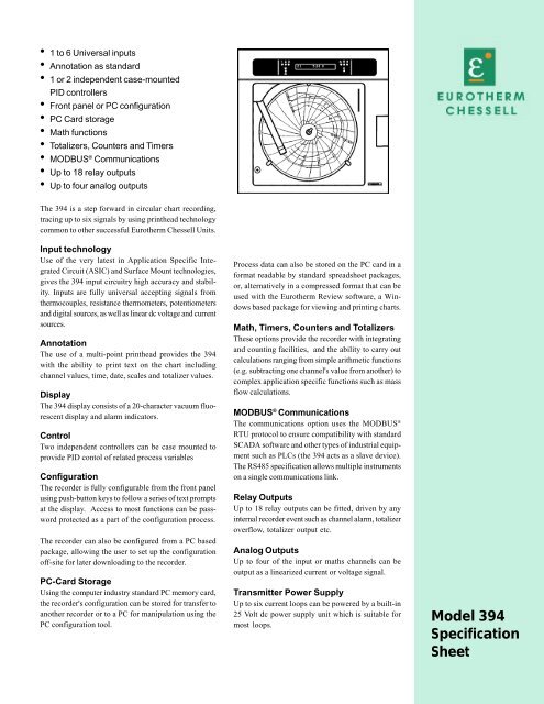
The <strong>394</strong> is a step forward in circular chart recording,<br />
tracing up to six signals by using printhead technology<br />
common to other successful Eurotherm Chessell Units.<br />
Input technology<br />
Use of the very latest in Application Specific Integrated<br />
Circuit (ASIC) and Surface Mount technologies,<br />
gives the <strong>394</strong> input circuitry high accuracy and stability.<br />
Inputs are fully universal accepting signals from<br />
thermocouples, resistance thermometers, potentiometers<br />
and digital sources, as well as linear dc voltage and current<br />
sources.<br />
Annotation<br />
The use of a multi-point printhead provides the <strong>394</strong><br />
with the ability to print text on the chart including<br />
channel values, time, date, scales and totalizer values.<br />
Display<br />
The <strong>394</strong> display consists of a 20-character vacuum fluorescent<br />
display and alarm indicators.<br />
Control<br />
Two independent controllers can be case mounted to<br />
provide PID contol of related process variables<br />
Configuration<br />
The recorder is fully configurable from the front panel<br />
using push-button keys to follow a series of text prompts<br />
at the display. Access to most functions can be password<br />
protected as a part of the configuration process.<br />
The recorder can also be configured from a PC based<br />
package, allowing the user to set up the configuration<br />
off-site for later downloading to the recorder.<br />
PC-Card Storage<br />
Using the computer industry standard PC memory card,<br />
the recorder's configuration can be stored for transfer to<br />
another recorder or to a PC for manipulation using the<br />
PC configuration tool.<br />
Process data can also be stored on the PC card in a<br />
format readable by standard spreadsheet packages,<br />
or, alternatively in a compressed format that can be<br />
used with the Eurotherm Review software, a Windows<br />
based package for viewing and printing charts.<br />
Math, Timers, Counters and Totalizers<br />
These options provide the recorder with integrating<br />
and counting facilities, and the ability to carry out<br />
calculations ranging from simple arithmetic functions<br />
(e.g. subtracting one channel's value from another) to<br />
complex application specific functions such as mass<br />
flow calculations.<br />
MODBUS ® Communications<br />
The communications option uses the MODBUS ®<br />
RTU protocol to ensure compatibility with standard<br />
SCADA software and other types of industrial equipment<br />
such as PLCs (the <strong>394</strong> acts as a slave device).<br />
The RS485 specification allows multiple instruments<br />
on a single communications link.<br />
Relay Outputs<br />
Up to 18 relay outputs can be fitted, driven by any<br />
internal recorder event such as channel alarm, totalizer<br />
overflow, totalizer output etc.<br />
Analog Outputs<br />
Up to four of the input or maths channels can be<br />
output as a linearized current or voltage signal.<br />
Transmitter Power Supply<br />
Up to six current loops can be powered by a built-in<br />
25 Volt dc power supply unit which is suitable for<br />
most loops.<br />
<strong>Model</strong> <strong>394</strong><br />
<strong>Specification</strong><br />
<strong>Sheet</strong>
TECHNICAL SPECIFICATION (Input board)<br />
General<br />
Input types<br />
Input type mix<br />
dc Volts, dc millivolts,<br />
dc milliamps (with shunt),<br />
Thermocouple,<br />
2/3-wire RTD<br />
Contact closure (not chan. 1) >500ms<br />
Freely configurable<br />
Maximum number of inputs 6<br />
Input ranges -38 to + 38 mV;<br />
- 150 to +150 mV;<br />
-1V to + 1 V;<br />
-10 to + 10 V<br />
Termination<br />
Terminal block<br />
Noise rejection (48 to 62Hz) Common mode: >130dB (channel to<br />
channel and channel to ground)<br />
Series mode: >60dB<br />
Maximum common mode voltage 250V continuous<br />
Maximum series mode voltage 45mV at lowest range;<br />
12Vpeak at highest range<br />
Isolation (dc to 65 Hz; BS EN61010) Installation cat. II; Pollution degree 2<br />
Channel - to - channel: 300V RMS or dc (double insulation)<br />
Channel - to - common electronics: 300V RMS or dc (double insulation)<br />
Channel - to - ground: 300V RMS or dc (basic insulation)<br />
Dielectric strength (BS EN61010) (1 minute type tests)<br />
Channel to channel 2300 Vac<br />
Channel to ground 1350 Vac<br />
Insulation resistance<br />
>10 MW at 500V dc<br />
Input resistance<br />
38mV, 150 mV, 1 V ranges: >10MΩ;<br />
10V range: 68.8 kΩ<br />
Over voltage protection (max) 42V RMS (between I and V-);<br />
50V RMS (I and V+) or (V+ and V-)<br />
Open circuit detection drive ± 57nA max<br />
Recognition time<br />
500ms<br />
Minimum break resistance<br />
10MΩ<br />
DC Input ranges<br />
Shunt/Attenuator<br />
Internally mounted resistor modules<br />
Additional error due to shunt 0.1% of input<br />
Additional error due to attenuator 0.2% of input<br />
Leakage current (Max) 38mV range: 1.7nA<br />
Other ranges:<br />
8nA<br />
Performance See table 1<br />
Input board specification (Cont.)<br />
Thermocouple data<br />
Temperature scale ITS 90<br />
Bias current (maximum)<br />
1.7nA<br />
Cold junction types<br />
Off, internal, external, remote<br />
CJ error 1°C max; instrument at 20°C<br />
CJ rejection ratio<br />
50:1 minimum<br />
Remote CJ<br />
Via any user-defined channel<br />
Upscale/downscale drive<br />
High, Low or None selectable for each<br />
thermocouple channel. Channels can<br />
be any mix of High and None or Low<br />
and None, but High and Low cannot be<br />
mixed.<br />
Types and ranges See table 2<br />
Table 2 Thermocouple types and ranges<br />
Resistance inputs<br />
Temperature scale<br />
ITS90<br />
Ranges (including lead resistance) 0 to 150Ω, 0 to 600Ω, 0 to 6kΩ<br />
Influence of lead resistance Error: Negligible (3-wire connection)<br />
Mismatch: 1Ω/Ω<br />
Wetting current<br />
250mA typical<br />
Resolution and accuracy See table 3<br />
RTD types and ranges See table 4<br />
Table 3 Resistance ranges resolution and accuracy<br />
Table 1 DC Performance<br />
Table 4 RTD types, ranges and acuracies<br />
INSTALLATION CATEGORY II<br />
The rated impulse voltage for equipment on nominal 230V mains is 2300V.<br />
POLLUTION DEGREE 2<br />
Normally, only non-conductive pollution occurs. Occasionally, however, a<br />
temporary conductivity caused by condensation shall be expected.
TECHNICAL SPECIFICATION (Recorder)<br />
Board types and hardware options<br />
Standard: Universal input/control board<br />
Options: Changeover relay output board<br />
Analog output board<br />
Communications board<br />
Transmitter Power Supply<br />
PID controller<br />
Case heater<br />
PC Card<br />
Environmental Performance<br />
Temperature limits Operation: 0 to 50°C<br />
(options can reduce maximum temp.)<br />
Storage: –20 to + 70°C<br />
Humidity limits (non-condensing) 10 to 90%<br />
Protection Standard: NEMA3 (IP54)<br />
Waterproof: NEMA4 (IP65)<br />
Shock<br />
BS EN60873 and BS EN61010<br />
Vibration (BS EN60873)<br />
1g peak at 60Hz to 150Hz<br />
Altitude (max.)
Electrical<br />
installation<br />
4<br />
5<br />
6<br />
+<br />
-<br />
+<br />
-<br />
+<br />
-<br />
+<br />
-<br />
+<br />
-<br />
+<br />
-<br />
Relay 1 Relay 2<br />
O<br />
Transmitter power supply N...2<br />
Fuse<br />
1<br />
2<br />
3<br />
Transmitter power supplyO<br />
N...1<br />
Fuse<br />
“Micro” board<br />
Option board 3<br />
(Re-transmission connections shown)<br />
Output 1 Output 2 Output 3 Output 4<br />
Input board<br />
Option board 2 Comms connections shown)<br />
TXA TXB CMN<br />
RXA RXB PU<br />
Option board (Relay connections shown)<br />
I V+ V- I V+ V- I V+ V- I V+ V- I V+ V- I V+ V-<br />
NO COMM NC<br />
NO COMM NC NO COMM NC NO COMM NC NO COMM NC NO COMM NC<br />
Chan 6 Chan 5 Chan 4 Chan 3 Chan 2<br />
Chan 1 Relay 3 Relay 4 Relay 5 Relay 6<br />
Cable clamp<br />
for mains lead<br />
E L N<br />
Connect supply voltage here<br />
Input board signal wiring<br />
I V+V-<br />
I V+V- I V+V- I V+V- I V+V- I V+V- I V+V-<br />
+ -<br />
DC V (-10V to +10V)<br />
DC mV<br />
Thermocouples<br />
Shunt<br />
assembly<br />
+ -<br />
Attenuator<br />
assembly<br />
(LA244180)<br />
+ -<br />
DCmA<br />
DC V<br />
(-100V to +100V)<br />
Shunt assembly: Attenuator assembly:<br />
100 = LA249885UK10 LA244180<br />
250 = LA249885UK25<br />
3-wire resistance<br />
thermometer<br />
2-wire resistance<br />
thermometer<br />
Potentiometer<br />
Closure must last >250ms.<br />
Contact closure<br />
(not channel 1 )<br />
EUROTHERM RECORDERS INC<br />
741-F MILLER DRIVE, LEESBURG, VA 20175-8993, USA TELEPHONE: 703-443-0000 FAX: 703-669-1302<br />
E-MAIL: sales@chessell.com WEB SITE: www.chessell.com<br />
HP260717X100 Issue 04/01