Combustible Gas - Axiom-Northwest
Combustible Gas - Axiom-Northwest
Combustible Gas - Axiom-Northwest

You also want an ePaper? Increase the reach of your titles
YUMPU automatically turns print PDFs into web optimized ePapers that Google loves.
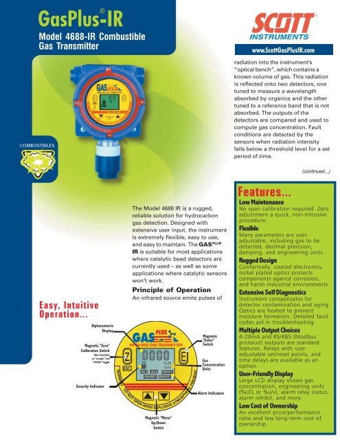
<strong>Gas</strong>Plus-IR<br />
®<br />
Model 4688-IR <strong>Combustible</strong><br />
<strong>Gas</strong> Transmitter<br />
www.Scott<strong>Gas</strong>PlusIR.com<br />
radiation into the instrument’s<br />
“optical bench”, which contains a<br />
known volume of gas. This radiation<br />
is reflected onto two detectors, one<br />
tuned to measure a wavelength<br />
absorbed by organics and the other<br />
tuned to a reference band that is not<br />
absorbed. The outputs of the<br />
detectors are compared and used to<br />
compute gas concentration. Fault<br />
conditions are detected by the<br />
sensors when radiation intensity<br />
falls below a threshold level for a set<br />
period of time.<br />
Easy, Intuitive<br />
Operation...<br />
The Model 4688 IR is a rugged,<br />
reliable solution for hydrocarbon<br />
gas detection. Designed with<br />
extensive user input, the instrument<br />
is extremely flexible, easy to use,<br />
and easy to maintain. The GAS PLUS<br />
IR is suitable for most applications<br />
where catalytic bead detectors are<br />
currently used – as well as some<br />
applications where catalytic sensors<br />
won’t work.<br />
Principle of Operation<br />
An infrared source emits pulses of<br />
Features...<br />
(continued...)<br />
Low Maintenance<br />
No span calibration required. Zero<br />
adjustment a quick, non-intrusive<br />
procedure.<br />
Flexible<br />
Many parameters are useradjustable,<br />
including gas to be<br />
detected, decimal precision,<br />
damping, and engineering units.<br />
Rugged Design<br />
Conformally coated electronics,<br />
nickel plated optics protects<br />
components against corrosion,<br />
and harsh industrial environments.<br />
Extensive Self Diagnostics<br />
Instrument compensates for<br />
detector contamination and aging.<br />
Optics are heated to prevent<br />
moisture formation. Detailed fault<br />
codes aid in troubleshooting.<br />
Multiple Output Choices<br />
4-20mA and RS/485 (Modbus<br />
protocol) outputs are standard<br />
features. Relays with user<br />
adjustable set/reset points, and<br />
time delays are available as an<br />
option.<br />
User-Friendly Display<br />
Large LCD display shows gas<br />
concentration, engineering units<br />
(%LEL or %v/v), alarm relay status,<br />
alarm inhibit, and more.<br />
Low Cost of Ownership<br />
An excellent price/performance<br />
ratio and low long-term cost of<br />
ownership.
Use and Maintenance<br />
Operation of the 4688IR is simple and intuitive. All settings and<br />
adjustments, such as alarm setpoints, gas measured, etc., are nonintrusive,<br />
performed at the instrument with a magnetic screwdriver<br />
– or remotely through the instrument’s RS/485 interface. Password<br />
protection prevents unauthorized personnel from tampering with<br />
the settings.<br />
Minimal maintenance is necessary. All span information is preset at<br />
the factory, and never needs to be adjusted. Zero adjustment is a<br />
quick, non-intrusive procedure. On-board diagnostics continuously<br />
check transmitter electronics, optics, and software for faults and<br />
indicate corrective action should a fault be detected. The field<br />
serviceable infrared emitter is replaced with a simple plug-in<br />
connection .<br />
Why IR?<br />
IR technology provides numerous advantages that<br />
may be benificial for your application’s conditions<br />
• Reduced maintenance (no span calibration required).<br />
• No saturation from high gas concentrations<br />
• No oxygen required for operation<br />
• Continuous sensor fault monitoring<br />
• Sensor lifetime not reduced by exposure to gas<br />
• Rapid speed of response<br />
• Minimal temperature and humidity effects<br />
Typical Specifications<br />
1. General. Transmitter shall be approved by<br />
a nationally recognized testing laboratory<br />
for Class 1, Division 1 Group B, C, and D<br />
hazardous locations. All parameter settings<br />
shall be password protectable. A large<br />
integral display shall provide visual<br />
indication of gas concentration,<br />
engineering units, alarm relay and inhibit<br />
status.<br />
2. Temperature and Power. Transmitter shall<br />
operate over an input range of 18-28VDC in<br />
ambient conditions of -40 C to 60°C and<br />
shall consume no more than 4.0 W<br />
maximum.<br />
3. Output. Transmitter shall provide an<br />
isolated, 4-20mA signal, and shall be<br />
digitally addressable using MODBUS<br />
protocol with RS/485 or RS/232 data<br />
transmission. Two SPST alarm relays shall<br />
be available as an option. User shall be able<br />
to separately adjust alarm set points, reset<br />
points, set delays, and reset delays. All<br />
alarm parameters shall be password<br />
protected and be non-intrusively adjustable<br />
through transmitter’s front panel via a<br />
manufacturer supplied magnet.<br />
4. Diagnostics. Transmitter shall conduct selfdiagnostics<br />
of electronics, software, and<br />
sensor at least twice per second. Fault<br />
conditions shall be indicated with a specific<br />
fault code on the instrument display and<br />
with a user-adjustable analog signal. One<br />
SPST fault relay shall be available as an<br />
option. User shall be capable of testing the<br />
alarm and fault relays from the instrument’s<br />
front panel or remotely via RS-232 / RS-<br />
485 communications interface.<br />
5. Calibration. All span calibration data shall<br />
be preset, with no additional span<br />
calibration required by user. Non-intrusive<br />
zero calibration shall be performed via<br />
magnet. Transmitter shall provide the<br />
ability to inhibit its output. A time-out<br />
feature shall automatically return the unit to<br />
normal operation mode after a preset<br />
amount of time. The calibration curve for<br />
the gas being monitored shall be user<br />
selectable in the field through the<br />
transmitter’s front panel via a manufacturer<br />
supplied magnet.<br />
6. Sensor. Sensor shall be non-dispersive<br />
infrared type using no moving mechanical<br />
parts. Linearity and repeatability shall be<br />
±2%LEL below 40% of full scale, and<br />
±5%LEL at or above 40% of full scale.<br />
Infrared emitter shall be field replacable.
Ordering Information<br />
Model 4688IR - A - B - C- D - E - F - G<br />
Includes Rainshield<br />
A: <strong>Gas</strong> Type<br />
1 - Standard <strong>Gas</strong>es (built-in)<br />
• Butane 0-100% LEL or 0-1.9% v/v Note 1<br />
• Ethane 0-100% LEL or 0-3.0% v/v<br />
• Hexane 0-100% LEL or 0-1.1% v/v<br />
• Methane 0-100% LEL or 0-5.0% v/v<br />
• Pentane 0-100% LEL or 0-1.5% v/v<br />
• Propane 0-100% LEL or 0-2.1% v/v<br />
• Propylene 0-100% LEL or 0-2.0% v/v<br />
2 - Extended <strong>Gas</strong> Set 1 Specify gas(es) (includes<br />
standard gases but not extended gas set 2)<br />
• Acetone 0-100% LEL or 0-2.5% v/vv<br />
• MEK 0-100% LEL or 0-1.5% v/v<br />
• Isopropyl Alcohol (IPA) 0-100% or 0-2.0%v/v<br />
• Pure Methane 0-100% v/v<br />
• Methanol 0 - 100% or 0 - 6% v/v<br />
• Toluene 0-100% LEL or 1.1%v/v<br />
3 - Extended <strong>Gas</strong> Set 2 Specify gas(es)<br />
(includes standard gases but not extended gas set 1)<br />
• Butadiene 0-100%LEL or 0-2% v/v<br />
• Ethylene 0-100% LEL or 2.7% v/v<br />
• Ethanol 0-100% or 3.3% v/v<br />
• Isobutanol 0-100% LEL or 1.7% v/v<br />
• Hexane 0-20% v/v NOTE 2<br />
• Benzene 0-100% LEL or 1.2 % v/v<br />
• Xylene 0-100% LEL or 1.1v/v<br />
4 - Other <strong>Gas</strong>es (contact factory)<br />
B: Remote Display/User Interface<br />
1 -Display integral with transmitter<br />
2 -Remote display/user interface<br />
with junction box - 50’ (15.2 meters) max<br />
separation<br />
C: Digital Protocol<br />
1 - RS-485 Note 3<br />
2 - RS-232<br />
D: Relays (non-failsafe mode of operation)<br />
1 - None<br />
2 - All Normally Open (NO)<br />
3 - All Normally Closed (NC)<br />
4 - Alarm NO, Fault NC<br />
5 - Alarm NC, Fault NO<br />
E: Optics Material<br />
1 - Nickel Plated aluminum<br />
2 - Stainless Steel<br />
F: Rating NOTE 4<br />
1 - Non CENELEC approved transmitter<br />
2 - CENELEC approved transmitter<br />
G: Rainshields<br />
1 - Standard<br />
2 - Flowcell (Nitrile O-ring)<br />
3 - Flowcell (Viton O-ring)<br />
4 - Flowcell (ethylene propylene)<br />
Ordering Notes<br />
• Not available for acetylene or H 2<br />
1. %v/v is in air<br />
2. Not for %LEL applications<br />
3. RS/485 includes 120Ω termination resistor which is user<br />
removable.<br />
4. "CENELEC approved" covers transmitter only. CENELEC<br />
approved enclosure includes metric conduit seal fitting; non-<br />
CENELEC approved enclosure includes NPT conduit seal fitting.<br />
Accessories<br />
Part # Description<br />
077-0120 magnetic screwdriver<br />
096-2201 RS-485 Termination<br />
Board<br />
096-2191 1/4 turn flowcell Note 2<br />
(Requires <strong>Gas</strong> Test Adaptor,#096-<br />
2192)<br />
074-0321 Rainshield<br />
096-2192 <strong>Gas</strong> Test Adaptor<br />
096-2289 Bump Test Adaptor<br />
096-2187 Zero Adjustment Kit<br />
(includes regulator,<br />
tubing, and carrying<br />
case - does NOT include<br />
methane "bump gas")<br />
096-2190 <strong>Gas</strong> test kit (2 ft tubing,<br />
zero air and methane<br />
“bump” gas”, cal<br />
adaptor, regulator, and<br />
carrying case)<br />
096-2215 Porex dust filter (for<br />
rainshield) pack of 5<br />
096-2214 Porex dust filter (for<br />
sensor) pack of 5<br />
077-0161 Emitter replacement tool<br />
096-2193 IR Emitter (plug-in,<br />
includes emitter<br />
replacement tool)<br />
<strong>Gas</strong>Plus Alarm System<br />
Optical Bench Assembly<br />
Engineered to handle difficult<br />
industrial enviroments yet<br />
incredibly easy to operate and<br />
maintain, the <strong>Gas</strong> Plus Alarm<br />
System provides visual and<br />
audible local alarm<br />
annunciation in a rugged steel<br />
enclosure.<br />
Designed for easy use and<br />
maintenance, the <strong>Gas</strong> Plus<br />
Alarm System can be equipped<br />
with either the Scott<br />
Instruments Model 4600 <strong>Gas</strong><br />
Plus Universal Toxic <strong>Gas</strong><br />
Transmitter, the Model 4688IR<br />
Infrared <strong>Combustible</strong> <strong>Gas</strong> Transmitter,<br />
or the Model 4679IR CO 2<br />
transmitter.<br />
Built-in strobe lights and an 80 db<br />
horn respond to two levels of alarm to quickly alert<br />
personnel of dangerous, build-ups of toxic or<br />
combustible gas. Three 10 amp relays provide additional<br />
response support for your facility, and a front panel light<br />
provides continuous visual indication of system status.<br />
The built-in 110 Vac power supply provides simple plugin<br />
electrical connection. Since all system adjustments<br />
are non-intrusive, the rugged painted or stainless steel<br />
enclosure never needs to be opened after installation.<br />
See the Alarm System datasheet for more information.
Technical Specifications<br />
GENERAL<br />
Sensor Type_____________ Non-dispersive infrared<br />
Detection Range ________ See “Ordering Information”<br />
Linearity ________________ ± 2% below 40% full scale<br />
± 5% from 40% to 110% full scale<br />
Repeatability ____________ ± 2% below 40% full scale<br />
± 5% from 40% to 110% full scale<br />
Response Time __________ T90 < 5 seconds (without<br />
rainshield)<br />
Start Up Time ___________ 30 seconds<br />
Self-Diagnostic Test ____ 2x per second<br />
Calibration ______________ Span: none (factory set)<br />
Zero: every 3 to 6 months<br />
User Interface ___________ Non-intrusive via magnet<br />
Display__________________ 4 digit LCD with user-adjustable<br />
contrast. Numeric display of gas<br />
concentration and faults; icons<br />
for alarms, lock, and inhibit<br />
Weight __________________ 6.5 lbs (3.0 kg)<br />
Warranty ________________ 2 years<br />
OUTPUTS<br />
Analog __________________ Isolated, 4-20mA, max loop load<br />
900ohms at 24 VDC (current<br />
source or sink)<br />
Programmable Fault_____ 2.4 to 4.0mA<br />
Programmable Inhibit ___ 1.5 to 20.0mA<br />
Programmable Loop Test 1.0 to 20.0mA<br />
Digital __________________ RS/485 or RS/232 using Modbus<br />
RTU or Modbus ASCII protocol<br />
Relay (optional) _________ 3 SPST relays (2 concentration, 1<br />
fault), 5A at 250 VAC. Userselectable<br />
latching/nonlatching,<br />
energized/de-energized, set/reset<br />
delay, and set/reset point<br />
ELECTRICAL<br />
Input Voltage____________ 18-27VDC<br />
Power Consumption ____ 3.1W, nominal / 6.0W, max<br />
Connections ____________ 3 wires or 4 wires (with RS/485 or<br />
RS/232 configuration ); 18-22<br />
AWG nominal<br />
RFI/EMI __________________ certified to EN50082-1<br />
ENVIRONMENTAL<br />
Operating Temp _________ -40°F to 140°F (-40°C to 60°C)<br />
Operating Humidity _____ 0 to 100% RH<br />
Installation Drawings<br />
Electrical<br />
Dimensions<br />
Bump Test Adaptor<br />
P/N 096-2289<br />
A(-)<br />
B(+)<br />
ENCLOSURE<br />
Enclosure Material ______ Copper-free cast aluminum, baked<br />
epoxy finish<br />
Optical Bench Material __ Stainless steel or electroplated<br />
aluminum<br />
APPROVALS<br />
Enclosure _______________ Explosion proof; UL/FM/CSA, Class<br />
1 Group B,C,D / Class 2, Group E, F<br />
/ Class 3, NEMA-4X, NEMA-7B, C,D;<br />
NEMA-9 E,F,G; IP66<br />
System __________________ ETL listed to UL2279 and UL3111-1<br />
(Class 1, Div 1, Group B,C,D ),<br />
CE Marked<br />
CSA approved to Class 1, Zone<br />
1,Groups IIB+H2;Class I, Groups<br />
E,F,&G; Class III<br />
CENELEC approved to EExd[ib] IIc T6<br />
Represented by:<br />
Toll Free US and Canada<br />
1-800-872-8008<br />
251 Welsh Pool Rd., Exton, PA 19341<br />
(PH) 610-363-5450 • (FAX) 610-363-0167<br />
(email) info@scottinstruments.com<br />
(WEB) www.scottinstruments.com<br />
or<br />
DS-4688-IR 08-02