download manual - noimmo
download manual - noimmo
download manual - noimmo

Create successful ePaper yourself
Turn your PDF publications into a flip-book with our unique Google optimized e-Paper software.
WSP Emulator automatic for Sprinter/Vito.<br />
The hereby product is intended to be installed instead original Immobilizer ECU.<br />
Purposes:<br />
1. CAN communication emulation between WSP (Immobilizer Unit) and ECU (CDI1/CDI2). We<br />
recommend to install it in case of «Start Error» message on instrument Cluster display.<br />
2. ECU EEPROM data changing. That data changing is needed for correctly functioning of<br />
emulator. Now you can change ECU data without ECU removing – just via K-line (via DLC). No<br />
need more takeoff (desolder) EEPROM microchip from ECU.<br />
1. ECU EEPROM data changing.<br />
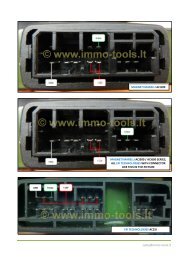
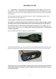
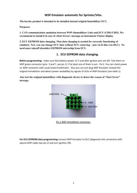
Before programming: make sure that battery power 12 V and after ignition pins are OK. Test them on<br />
WSP green connector (pins 3 and 7, see pic.1). If at least one of them is out – fix it. You can check power<br />
on WSP connector with usual tester/multimeter . Also you can just plug WSP Emulator instead the<br />
original immobilizer and detect power availability by signals of LEDs of WSP Emulator (see table 1).<br />
Also test the original immobilizer with diagnostic device to detect the reason of “Start Error”<br />
message.<br />
IGNITION - 7<br />
2 - GND<br />
3 - BATTERY<br />
Pic.1 WSP immobilizer connector.<br />
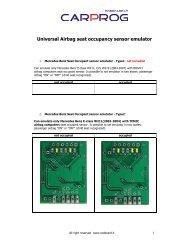
For ECU EEPROM data programming connect WSP Emulator to DLC (diagnostic link connector) with<br />
special WSP cable (see pic.2) and turn ignition ON.<br />
1
Pic.2. WSP cable.<br />
If green LED is ON – all power pins on WSP connector are OK. You can control programming process and<br />
programming results during and after programming by combination of LEDs – one green and three red<br />
(see pic.3)<br />
4<br />
3<br />
2<br />
1<br />
Pic3. WSP Emulator’s LEDs.<br />
2
Table 1.<br />
LEDs modes combinations.<br />
LED’s number(according pic.3)<br />
1 2 3 4<br />
LEDs signals value<br />
Bad connection with ECU or low power on WSP pins.<br />
CDI1 has been programmed successfully<br />
CDI2 has been programmed successfully<br />
Error programming of CDI1<br />
Error programming of CDI2<br />
12 V after ignition is OUT on WSP connector<br />
- OFF<br />
Or - ON<br />
- blinking<br />
2. WSP signal emulation mode<br />
When you programmed ECU successfully disconnect WSP cable and connect WSP Emulator<br />
instead original immobilizer box.<br />
If all WSP connector’s power voltages are OK:<br />
- Green LED (4) is ON<br />
- Red LED (3) blinking shortly<br />
3