DS1813 5V EconoReset with Pushbutton
DS1813 5V EconoReset with Pushbutton
DS1813 5V EconoReset with Pushbutton

You also want an ePaper? Increase the reach of your titles
YUMPU automatically turns print PDFs into web optimized ePapers that Google loves.
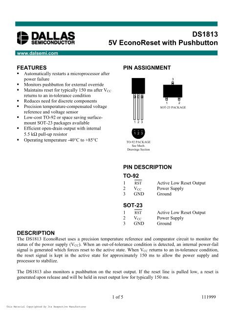
<strong>DS1813</strong><br />
<strong>5V</strong> <strong>EconoReset</strong> <strong>with</strong> <strong>Pushbutton</strong><br />
www.dalsemi.com<br />
FEATURES<br />
<br />
<br />
<br />
<br />
<br />
<br />
<br />
<br />
Automatically restarts a microprocessor after<br />
power failure<br />
Monitors pushbutton for external override<br />
Maintains reset for typically 150 ms after V CC<br />
returns to an in-tolerance condition<br />
Reduces need for discrete components<br />
Precision temperature-compensated voltage<br />
reference and voltage sensor<br />
Low-cost TO-92 or space saving surfacemount<br />
SOT-23 packages available<br />
Efficient open-drain output <strong>with</strong> internal<br />
5.5 kΩ=pull-up resistor<br />
Operating temperature -40°C to +85°C<br />
PIN ASSIGNMENT<br />
1 2 3<br />
1 2 3<br />
TO-92 PACKAGE<br />
See Mech.<br />
Drawings Section<br />
3<br />
1 2<br />
SOT-23 PACKAGE<br />
PIN DESCRIPTION<br />
TO-92<br />
1 RST Active Low Reset Output<br />
2 V CC Power Supply<br />
3 GND Ground<br />
SOT-23<br />
1 RST Active Low Reset Output<br />
2 V CC Power Supply<br />
3 GND Ground<br />
DESCRIPTION<br />
The <strong>DS1813</strong> <strong>EconoReset</strong> uses a precision temperature reference and comparator circuit to monitor the<br />
status of the power supply (V CC ). When an out-of-tolerance condition is detected, an internal power-fail<br />
signal is generated which forces reset to the active state. When V CC returns to an in-tolerance condition,<br />
the reset signal is kept in the active state for approximately 150 ms to allow the power supply and<br />
processor to stabilize.<br />
The <strong>DS1813</strong> also monitors a pushbutton on the reset output. If the reset line is pulled low, a reset is<br />
generated upon release and will be held in reset output low for typically 150 ms.<br />
1 of 5 111999
<strong>DS1813</strong><br />
OPERATION - POWER MONITOR<br />
The <strong>DS1813</strong> provides the functions of detecting out-of-tolerance power supply conditions and warning a<br />
processor-based system of impending power failure. When V CC is detected as out-of-tolerance, the RST<br />
signal is asserted. On power-up, RST is kept active for approximately 150 µs after the power supply has<br />
reached the selected tolerance. This allows the power supply and microprocessor to stabilize before RST<br />
is released.<br />
OPERATION - PUSHBUTTON RESET<br />
The <strong>DS1813</strong> provides for a pushbutton switch for manual reset control. When the <strong>DS1813</strong> is not in a reset<br />
cycle, a pushbutton reset can be generated by pulling the RST pin low for at least 1 ms. When the<br />
pushbutton is held low, the RESET is forced active low and will remain active low for about 150 ms after<br />
the pushbutton is released. See Figure 2 for an application example and Figure 3 for the timing diagram.<br />
BLOCK DIAGRAM (OPEN-DRAIN OUTPUT) Figure 1<br />
APPLICATION EXAMPLE Figure 2<br />
2 of 5
TIMING DIAGRAM: PUSHBUTTON RESET Figure 3<br />
<strong>DS1813</strong><br />
TIMING DIAGRAM: POWER-UP Figure 4<br />
TIMING DIAGRAM: POWER-DOWN Figure 5<br />
3 of 5
ABSOLUTE MAXIMUM RATINGS*<br />
Voltage on V CC Pin Relative to Ground<br />
Voltage on RST Relative to Ground<br />
Operating Temperature<br />
Storage Temperature<br />
Soldering Temperature<br />
-0.<strong>5V</strong> to +7.0V<br />
-0.<strong>5V</strong> to +<strong>5V</strong> CC +0.<strong>5V</strong><br />
-40°C to +85°C<br />
-55°C to +125°C<br />
260°C for 10 seconds<br />
<strong>DS1813</strong><br />
* This is a stress rating only and functional operation of the device at these or any other conditions<br />
above those indicated in the operation sections of this specification is not implied. Exposure to<br />
absolute maximum rating conditions for extended periods of time may affect reliability.<br />
RECOMMENDED DC OPERATING CONDITIONS<br />
(-40°C to +85°C)<br />
PARAMETER SYMBOL MIN TYP MAX UNITS NOTES<br />
Supply Voltage V CC 0.0 5.5 V 1<br />
DC ELECTRICAL CHARACTERISTICS<br />
(-40°C to +85°C; V CC =1.2V to 5.<strong>5V</strong>)<br />
PARAMETER SYMBOL MIN TYP MAX UNITS NOTES<br />
Output Current @ 0.4 volts I OL +10 mA 2, 3<br />
Voltage Input Low V IL 0.4 V 1<br />
Voltage Input High V IH 0.7<br />
V 1<br />
*V CC<br />
Operating Current V CC < 5.5 I CC 30 40 µA 4<br />
V CC Trip Point (<strong>DS1813</strong>-5) V CCTP 4.50 4.62 4.75 V 1<br />
V CC Trip Point (<strong>DS1813</strong>-10) V CCTP 4.25 4.35 4.49 V 1<br />
V CC Trip Point (<strong>DS1813</strong>-15) V CCTP 4.00 4.13 4.24 V 1<br />
Internal Pull-Up Resistor R P 3.50 5.5 7.5 k 6<br />
Output Capacitance C OUT 10 pF<br />
AC ELECTRICAL CHARACTERISTICS<br />
(-40°C to +85°C; V CC =1.2V to 5.<strong>5V</strong>)<br />
PARAMETER SYMBOL MIN TYP MAX UNITS NOTES<br />
RESET Active Time t RST 100 150 300 ms<br />
V CC Detect to RST t RPD 2 5 µs<br />
V CC Slew Rate<br />
(V CCTP (MAX) - V CCTP (MIN))<br />
V CC Slew Rate<br />
(V CCTP (MIN) - V CCTP (MAX))<br />
t F 300 µs 7<br />
t R 0 ns<br />
V CC Detect to RST t RPU 100 150 300 ms 5<br />
<strong>Pushbutton</strong> Detect to RST t PB 1 µs<br />
<strong>Pushbutton</strong> Reset t PBRST 100 150 300 ms<br />
4 of 5
NOTES:<br />
1. All voltages are referenced to ground.<br />
2. Measured <strong>with</strong> V CC ≥ 2.7 volts.<br />
3. A 1kΩ=external resistor may be required in some applications for proper operation of the<br />
microprocessor reset control circuit.<br />
<strong>DS1813</strong><br />
4. Measured <strong>with</strong> RST output open.<br />
5. t R = 5 µs.<br />
6. V OH and I OH are a function of the value of R P and the associated output load conditions.<br />
7. This value is for reference in defining values for T RPD and should not be considered a requirement for<br />
proper operation or use of the device.<br />
PART MARKING CODES<br />
“A”, “B”, &“C” represent the device type.<br />
810 . . . . DS1810<br />
811 . . . . DS1811<br />
812 . . . . DS1812<br />
813 . . . . <strong>DS1813</strong><br />
815 . . . . DS1815<br />
816 . . . . DS1816<br />
817 . . . . DS1817<br />
818 . . . . DS1818<br />
“D” represents the device tolerance.<br />
A . . . . . . 5%<br />
B . . . . . . 10%<br />
C . . . . . . 15%<br />
D . . . . . . 20%<br />
5 of 5