08 FTR-B4 Series -2
08 FTR-B4 Series -2
08 FTR-B4 Series -2

Create successful ePaper yourself
Turn your PDF publications into a flip-book with our unique Google optimized e-Paper software.
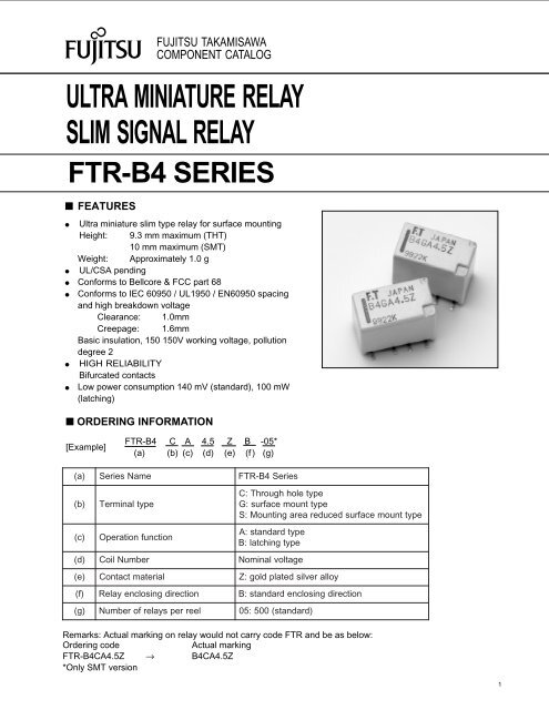
FUJITSU TAKAMISAWACOMPONENT CATALOGULTRA MINIATURE RELAYSLIM SIGNAL RELAY<strong>FTR</strong>-<strong>B4</strong> SERIES■ FEATURES● Ultra miniature slim type relay for surface mountingHeight: 9.3 mm maximum (THT)10 mm maximum (SMT)Weight: Approximately 1.0 g● UL/CSA pending● Conforms to Bellcore & FCC part 68● Conforms to IEC 60950 / UL1950 / EN60950 spacingand high breakdown voltageClearance: 1.0mmCreepage: 1.6mmBasic insulation, 150 150V working voltage, pollutiondegree 2● HIGH RELIABILITYBifurcated contacts● Low power consumption 140 mV (standard), 100 mW(latching)■ ORDERING INFORMATION[Example]<strong>FTR</strong>-<strong>B4</strong> C A 4.5 Z B -05*(a) (b) (c) (d) (e) (f ) (g)( a) <strong>Series</strong>Name( b) Terminal type( c) Operation function( d) CoilNumber( e) Contactmaterial( f) Relayenclosing direction<strong>FTR</strong>-<strong>B4</strong> <strong>Series</strong>C: Through hole typeG: surface mount typeS: Mounting area reduced surface mount typeA: standard typeB: latching typeNominal voltageZ: gold plated silver alloyB: standard enclosing direction( g) N umber of relays per reel05: 500 (standard)Remarks: Actual marking on relay would not carry code <strong>FTR</strong> and be as below:Ordering codeActual marking<strong>FTR</strong>-<strong>B4</strong>CA4.5Z → <strong>B4</strong>CA4.5Z*Only SMT version1
<strong>FTR</strong>-B2 <strong>Series</strong>■ COIL DATA CHARTStandard typeMODELRated coilvoltageCoil resistance(±10%)OperatingvoltageReleasevoltage*Rated powerconsumption<strong>FTR</strong>-<strong>B4</strong>(<strong>FTR</strong>-<strong>B4</strong>(<strong>FTR</strong>-<strong>B4</strong>(<strong>FTR</strong>-<strong>B4</strong>()A1.5Z)A003Z)A4.5Z)A012Z1.5VDC16.1 + 1.13V+ 0.15V140mW3VDC64.3 + 2.25V+ 0.3V140mW4.5VDC145+ 3.38V+ 0.45V140mW12VDC1,028+ 9.0V+ 1.2V140mW* Pulse drivenNote: All values in the table are measured at 20˚C.Latching type (1 coil)<strong>FTR</strong>-<strong>B4</strong><strong>FTR</strong>-<strong>B4</strong><strong>FTR</strong>-<strong>B4</strong><strong>FTR</strong>-<strong>B4</strong>MODEL( )B1.5Z( )B003Z( )<strong>B4</strong>.5Z( )B012ZRated coilvoltageCoil resistance(±10%)SetvoltageReleasevoltageRated powerconsumption1.5VDC22.5 + 1.13V1.13V100mW3VDC90+ 2.25V2.25V100mW4.5VDC203+ 3.38V3.38V100mW12VDC1,440+ 9.0V9.0V100mW* Pulse drivenNote: All values in the table are measured at 20˚C.2
<strong>FTR</strong>-B2 <strong>Series</strong>■ SPECIFICATIONSStandardTypeLatching TypeContactArrangementContactItemmaterial2Form C<strong>FTR</strong>-<strong>B4</strong>CA ( ) Z<strong>FTR</strong>-<strong>B4</strong>GA ( ) Z<strong>FTR</strong>-<strong>B4</strong>SA ( ) ZGold overlay silver alloyC ontact resistance ( initialvalue)100mmaximumat6VDC1AMaximum switchingMaximum switchingMaximum switchingcurrentpowervoltageC oil Operatingtemperature (no frost)Time ValueInsulationLifeVibrationResistanceShockResistanceWeightUL/CSA1A62.5 VA / 30W250 VAC, 220 VDC-40˚ C to +85˚ CO perate ( atnominalvoltage,withoutbounce)3ms maximumR elease ( atnominalvoltage,withoutbounce)3ms maximumResistanceDielectricStrengthSurgeStrength(at 500VDC)betweenbetweenbetweenopen contactsadjacent contactscoil and contactsMinimum 1,000 M1,000 VAC 1 minute1,000 VAC 1 minute1,500 VAC 1 minuteb etween open contacts 1,500V (at 10 x 160µs) [FCC Part 68]b etween adjacent contacts 1,500V (at 10 x 160µs) [FCC Part 68]between coil and contacts1,500V (at 10 x 160µs) [FCC Part 68]2,500V (at 2 x 10µs) [Bellcore]6Mechanical50x 10operations (at 3 Hz)Electrical (resistive load)MisoperationEnduranceMisoperationEnduranceContactRating<strong>FTR</strong>-<strong>B4</strong>CB ( ) Z<strong>FTR</strong>-<strong>B4</strong>GB ( ) Z<strong>FTR</strong>-<strong>B4</strong>SB ( ) Z3100x 10 ops. min. at 1 A, 30 VDC (at .5 Hz)3100x 10 ops. min. at .3 A, 30 VAC (at .5 Hz)10 to 55 Hz at double amplitude of 3 mm10 to 55 Hz at double amplitude of 5 mm2Min.750 m/ s2Min.1000 m/ sApproximately 1.0 g.5 A, 125 VAC; 1A, 30 VDC; .3 A, 110 VDC*1 Minimum switching loads mentioned above are reference values. Please perform the confirmation test withthe actual load before production since reference values may vary according to switching frequencies, environmental conditions adn expected reliability levels.3
<strong>FTR</strong>-B2 <strong>Series</strong>■ DIMENSIONS AND SCHEMATICSThrough hole typeSurface mount type (standard)5.7 ±0.310.6 ±0.31.5 ±0.2 3.2 ±0.2 2.2 ±0.2 2.2 ±0.2 0.4 ±0.19 ±0.33.54 ±0.3 0.5 ±0.17.63.2 2.28-ø0.85(+)]2 3 43.25.7 ±0.310.6 ±0.30.2 ±0.050.51.5 ±0.2 3.2 ±0.2 2.2 ±0.2 2.2 ±0.2 0.4 ±0.19 ±0.30.2 ±0.053.2 ±0.37.4 ±0.31.29.7 ±0.33.2±0.23.17.63.2 2.2(-)87 6 53.15.38(-)7 6 50.81(+)2 3 4Recommended mounting pad(Tolerance: ±0.1mm)Terminal designations(Bottom view deenergizedposition)Recommended mounting pad(Tolerance: ±0.1mm)Terminal designations(Bottom view deenergizedposition)4
<strong>FTR</strong>-B2 <strong>Series</strong>■ DIMENSIONS AND SCHEMATICSMounting area reduced mount type10.6 ±0.30.59 ±0.35.7 ±0.31.5 ±0.2 3.2 ±0.2 2.2 ±0.2 2.2 ±0.2 0.4 ±0.10.2 ±0.057.63.2 2.2(-)87 6 52.254.452.251.29.7 ±0.33.2 ±0.35.7 ±0.30.81(+)2 3 4Recommended mounting pad(Tolerance: ±0.1mm)Terminal designations(Bottom view deenergizedposition)■ RECOMMENDED SOLDERING CONDITIONS(TEMPERATURE PROFILE)Note:Temperature (°C)T 3T 2T 1IRS (Infrared Reflow Soldering)preheatingsolderingcoolingT 3 = 245°C max.T 2 = 200°C max.T 1 = 165°C max.1.Temperature profiles show the temperature of PC board surface.2. Please perform soldering test with youractual PC board before mass production, since the temperatures of PCboard surfaces vary according to thesize of PC board, status of parts mounting and heating method.0120 sec maximum30 secMax.5
<strong>FTR</strong>-B2 <strong>Series</strong>■ PRECAUTIONS- For details on general precautions, refer to the section on technical descriptions.- Since this is a polar relay, follow the instructions of the internal wiring diagram for the +- connections of the coil.- Note that the terminal array and internal wiring of the surface mount relay are a top view.Fujitsu TakamisawaInternationalHeadquarterOfficeswww.fujitsu.takamisawa.comJapanFujitsu Takamisawa Component LimitedGlobal Marketing and SalesGotanda-Chuo Building3-5, Higashigotanda 2-chome, Shinagawa-kuTokyo 141, JapanTel: (81-3) 5449-7010Fax: (81-3) 5449-2626North and South AmericaFujitsu Takamisawa America, Inc.250 E. Caribbean DriveSunnyvale, CA 94<strong>08</strong>9 U.S.A.Tel: (1-4<strong>08</strong>) 745-4900Fax: (1-4<strong>08</strong>) 745-4970EuropeFujitsu Takamisawa Europe B.V.Diamantlaan 252132 WV HoofddorpNetherlandsTel: (31-23) 5560910Fax: (31-23) 5560950Asia PacificFujitsu Takamisawa Asia Pacific Pte. Ltd.102E Pasir Panjang Road#04-01 Citilink Warehouse ComplexSingapore 118529Tel: (65) 375-8560Fax: (65) 273-30216