4009 and LED Scoreboards Manual - Colorado Time Systems
4009 and LED Scoreboards Manual - Colorado Time Systems
4009 and LED Scoreboards Manual - Colorado Time Systems

Create successful ePaper yourself
Turn your PDF publications into a flip-book with our unique Google optimized e-Paper software.
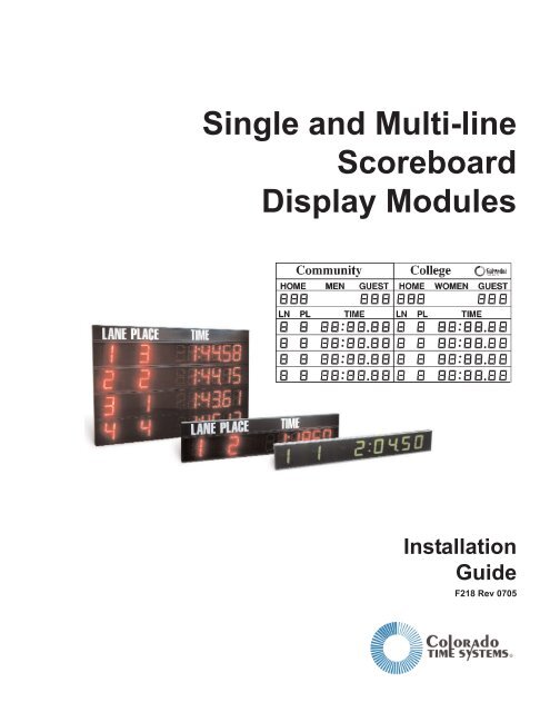
Single <strong>and</strong> Multi-line<br />
Scoreboard<br />
Display Modules<br />
Installation<br />
Guide<br />
F218 Rev 0705
<strong>Colorado</strong> <strong>Time</strong> <strong>Systems</strong><br />
Corporate Office<br />
1551 East 11th Street<br />
Lovel<strong>and</strong>, CO 80537 USA<br />
Sales : 800-279-0111 or +1 970-667-1000<br />
Service: 800-287-0653 x256 or +1 970-667-1000 x256<br />
Service Fax: 970-667-1032<br />
Web: www.coloradotime.com<br />
Email: customerservice@coloradotime.com<br />
Part Number F218, Rev. 0705<br />
©2005 <strong>Colorado</strong> <strong>Time</strong> <strong>Systems</strong>. All rights reserved.
Table of Contents<br />
1 Introduction<br />
Receiving Your Equipment . . . . . . . . . . . . . . . . . . . . . .1-1<br />
Scoreboard Package Contents. . . . . . . . . . . . . . . . . . . . 1-1<br />
Scope of this Instruction Guide . . . . . . . . . . . . . . . . . . .1-2<br />
CE <strong>and</strong> UL Information . . . . . . . . . . . . . . . . . . . . . . . .1-3<br />
2 Electrical <strong>and</strong> Data Cable Requirements<br />
Electrical Wiring . . . . . . . . . . . . . . . . . . . . . . . . . . . . . .2-1<br />
Data Cable Wiring . . . . . . . . . . . . . . . . . . . . . . . . . . . . .2-4<br />
Permanent Data Cabling . . . . . . . . . . . . . . . . .2-4<br />
Installing the Removable Cable . . . . . . . . . . . .2-4<br />
Installing Signage . . . . . . . . . . . . . . . . . . . . . . . . . . . . .2-5<br />
3 Mounting Your Scoreboard<br />
Preparing Scoreboard Display Lines for Mounting . . .3-1<br />
Mounting Sign Panels . . . . . . . . . . . . . . . . . . .3-1<br />
Arranging Scoreboard Display Digits . . . . . . .3-2<br />
Setting Display Module Switches . . . . . . . . . .3-4<br />
Testing Scoreboard Display Lines . . . . . . . . . .3-6<br />
Installing Brackets <strong>and</strong> Unistruts . . . . . . . . . . . . . . . .3-7<br />
Measurements . . . . . . . . . . . . . . . . . . . . . . . . . .3-7<br />
Installing Mounting Brackets . . . . . . . . . . . . .3-9<br />
Mounting <strong>and</strong> Leveling Unistruts . . . . . . . . . .3-12<br />
Mounting Scoreboard Display Lines . . . . . . . .3-14<br />
Optional Unistrut Covers . . . . . . . . . . . . . . . .3-16<br />
4 Connecting <strong>and</strong> Testing Your Scoreboard<br />
Linking a Multi-line Scoreboard . . . . . . . . . . . . . . . . . .4-1<br />
Attaching Data Cables . . . . . . . . . . . . . . . . . . . . . . . . . .4-1<br />
Powering Up Your Scoreboard . . . . . . . . . . . . . . . . . . .4-2<br />
Final Testing . . . . . . . . . . . . . . . . . . . . . . . . . . . . . . . . .4-2<br />
5 Troubleshooting <strong>and</strong> Service<br />
Troubleshooting . . . . . . . . . . . . . . . . . . . . . . . . . . . . . . .5-1<br />
Service . . . . . . . . . . . . . . . . . . . . . . . . . . . . . . . . . . . . . .5-3<br />
Removing a Digit . . . . . . . . . . . . . . . . . . . . . . .5-3<br />
Segment Base Clip & Bearing Replacement . . 5-4<br />
Removing/Replacing Digits . . . . . . . . . . . . . . .5-6<br />
Removing/Replacing a Control Board . . . . . . .5-7<br />
TOCi
TOCii
1<br />
Introduction<br />
Thank you for purchasing a <strong>Colorado</strong> <strong>Time</strong> <strong>Systems</strong> Scoreboard Display.<br />
Whether you have chosen light-reflective digits or <strong>LED</strong> digits, your display<br />
will enhance your program <strong>and</strong> provide exceptional visibility. Best of all,<br />
you will never change another light bulb. Designed specifically for the<br />
swimming pool environment, your scoreboard’s high-quality construction<br />
resists corrosion in any environment, giving you years of trouble-free service.<br />
The scoreboard is an integral part of your <strong>Colorado</strong> <strong>Time</strong> <strong>Systems</strong>’ sports<br />
timer package. It displays results <strong>and</strong> other information for Swimming,<br />
Diving, Water Polo, Synchronized Swimming, Track, <strong>and</strong> more. It can also<br />
be used as a training pace clock in conjunction with your CTS sports timer<br />
<strong>and</strong> Pace Clock software.<br />
Before You Begin<br />
Scoreboard<br />
Package Contents<br />
Proper installation of your new scoreboard is very important. Please read<br />
this installation guide carefully before installing your scoreboard to make<br />
sure you have everything you need before beginning. When you are ready<br />
to install your scoreboard, carefully follow the step-by-step instructions in<br />
this manual. If you should experience any difficulties installing or using<br />
your new scoreboard, check the Troubleshooting <strong>and</strong> Maintenance sections<br />
in this manual first. If you are still unable to correct the problem,<br />
call <strong>Colorado</strong> <strong>Time</strong> <strong>Systems</strong>’ Customer Service Department (x256) toll-free<br />
at 1-800-287-0653 in the US <strong>and</strong> Canada, or (970) 667-1000.<br />
Before you begin to install your new scoreboard, check all parts received<br />
against the packing list <strong>and</strong> your order to ensure that you received all necessary<br />
parts. If any parts are missing, call <strong>Colorado</strong> <strong>Time</strong> <strong>Systems</strong>’<br />
Customer Service Department (x256) toll-free at 1-800-287-0653 in the<br />
U.S. <strong>and</strong> Canada, or (970) 667-1000.<br />
Although each scoreboard package is custom assembled to match the customer’s<br />
order, many items are always included. The quantity of each item<br />
you receive depends on your order. Some items are only included in multiline<br />
scoreboard packages.<br />
<br />
<br />
<br />
<br />
<br />
<br />
<br />
<br />
<br />
<br />
<br />
Scoreboard display line(s)<br />
Sign panel(s)<br />
Signage transfer(s)<br />
Sign panel mounting brackets <strong>and</strong> hardware<br />
Removable data cable<br />
Scoreboard link data cables (multi-line only)<br />
Unistruts<br />
Universal mounting brackets<br />
“U” mounting brackets<br />
Mounting bracket hardware<br />
Installation guide<br />
1-1
Scope of this Instruction Guide<br />
This installation guide covers all aspects of a normal scoreboard installation.<br />
It is not intended to address every possible scoreboard configuration<br />
or mounting scheme. It is intended to provide enough information so that<br />
you can easily adapt the instructions to meet your specific requirements.<br />
This installation guide also includes Troubleshooting <strong>and</strong> Maintenance<br />
sections which cover the most common user correctable problems <strong>and</strong><br />
maintenance issues.<br />
To find specific information quickly, refer to the Table of Contents at the<br />
front of this installation guide. For answers to installation questions or<br />
problems not covered here, call <strong>Colorado</strong> <strong>Time</strong> <strong>Systems</strong>’ Customer Service<br />
Department (x256) at 1-800-287-0653 in the U.S. <strong>and</strong> Canada, or (970)<br />
667-1000.<br />
1-2
Product Specifications<br />
Environmental<br />
Temperature: 0°C - 50°C<br />
Humidity: 90% (non-condensing)<br />
Altitude: 0 to 3000 m<br />
Electrical<br />
Supply Voltages:<br />
U.S.<br />
AC Supply: 115 VAC ±10% @ 3.0A, 50-60Hz<br />
International<br />
AC Supply: 230 VAC ±10% @ 1.5A, 50-60Hz<br />
Fuses:<br />
<strong>4009</strong>:<br />
Primary - 3A, 250V, <strong>Time</strong> Lag, 5mm x 20mm<br />
Secondary - 5A, 250V, <strong>Time</strong> Lag, 5mm x 20mm<br />
<strong>LED</strong>:<br />
5A, 250V, <strong>Time</strong> Lag, 5mm x 20mm<br />
Input <strong>and</strong> Output Connections<br />
SCBD Port: Input - RS-232, ±12V<br />
Symbols<br />
Protective<br />
Conductor<br />
Terminal<br />
Fuse<br />
Alternating<br />
Current<br />
1-3
Installation/Maintenance<br />
This product is intended to be used in an indoor or outdoor swimming pool<br />
environment. When the scoreboard is operated in the U.S. it must be used<br />
in accordance with the National Electric Code. When the scoreboard is<br />
operated elsewhere it must be used in accordance with all appropriate<br />
national <strong>and</strong> local electrical codes <strong>and</strong> regulations for the country of installation.<br />
The AC power cord should not be accessible during normal operations.<br />
Connect only to a circuit that is protected by a ground-fault circuit<br />
interrupter (GFCI).<br />
These scoreboards are equipped with a 3-wire grounding-type plug, a plug<br />
having a third (grounding) pin. This plug will only fit into a groundingtype<br />
power outlet. This is a safety feature. If you are unable to insert the<br />
plug into the outlet, contact a qualified electrician to replace your obsolete<br />
outlet. Do not defeat the purpose of the grounding-type plug.<br />
Using these scoreboards in a manner not specified by <strong>Colorado</strong> <strong>Time</strong><br />
<strong>Systems</strong> may cause the protection provided by the equipment to be<br />
impaired.<br />
Other than those maintenance items described in the user manual, there<br />
are no user serviceable parts on these scoreboards. When servicing those<br />
parts shown in the user manual, use only replacement parts specified.<br />
When replacing fuses or any similar servicing of the unit, make sure the<br />
unit is unplugged.<br />
It is recommended that these scoreboards be installed by <strong>Colorado</strong> <strong>Time</strong><br />
<strong>Systems</strong> personnel. However, if you have chosen to install the board without<br />
a CTS technician <strong>and</strong> you experience difficulties, check the<br />
Troubleshooting <strong>and</strong> Maintenance sections in this manual first. If you are<br />
still unable to correct the problem, call <strong>Colorado</strong> <strong>Time</strong> <strong>Systems</strong>’ Customer<br />
Service Department (x256) toll-free at 1-800-287-0653 in the U.S. <strong>and</strong><br />
Canada, or (970) 667-1000 for assistance or to schedule a technician for<br />
your installation.<br />
1-4
Produkt Spezifikationen<br />
Umgebung<br />
Temperatur: 0°C - 50°C<br />
Luftfeuchtigkeit: 90% (nicht-kondensierend)<br />
Höhe: 0 bis 3000 m<br />
Elektrizität<br />
Stromversorgung:<br />
U.S.<br />
AC Verorgung: 115 VAC ±10% @ 3.0A, 50-60Hz<br />
International<br />
AC Verorgung: 230 VAC ±10% @ 1.5A, 50-60Hz<br />
Sicherungen:<br />
<strong>4009</strong>:<br />
Primär - 3A, 250V, Träge, 5mm x 20mm<br />
Sekundär - 5A, 250V, Träge, 5mm x 20mm<br />
10<strong>LED</strong>-8R/8RO:<br />
2A, 250V, Träge, 5mm x 20mm<br />
Eingänge und Ausgänge<br />
SCBD Ausgang: Input - RS-232, ±12V<br />
Installation<br />
Dieses Produkt kann für innen und außen benutzt werden. Die<br />
Installation der Anzeigetafel muß nach den Vorschriften der entsprechenden<br />
Länder erfolgen.<br />
Das AC Stromversorgungskabel solite geschützt und während des<br />
Betriebes nicht zugänglich sein.<br />
Wenn die Anzeigetafein nicht so insalliert werden wie von CTS spezifiziert,<br />
kann die Funktion beerinträchtigt werden.<br />
Es gibt keine weiteren notwendigen Service-Wartungsarbeiten für die<br />
Anzeigetafel-Serien als die in dem H<strong>and</strong>buch anfgeführten positionen.<br />
Die Anzeigetafel-Serien sollten nur van autorisiertem Personal oder von<br />
der Firma <strong>Colorado</strong> <strong>Time</strong> <strong>Systems</strong> installiert werden.<br />
Schutzleiter<br />
Sicherung<br />
Wechselspannung<br />
Symbole<br />
1-5
1-6
Electrical <strong>and</strong> Data Cable Requirements<br />
2<br />
Electrical Wiring<br />
Note<br />
This chapter contains instructions for electrical <strong>and</strong> data cable wiring<br />
which must be completed before you install your scoreboard. Follow these<br />
instructions carefully.<br />
All electrical wiring must be carried out in accordance with the applicable<br />
national, state <strong>and</strong> local electrical codes. All electrical wiring should<br />
be done by a qualified electrician.<br />
This section contains the <strong>Colorado</strong> <strong>Time</strong> <strong>Systems</strong>’ recommended methods<br />
of providing power to your new scoreboard. Follow these recommendations<br />
during your installation.<br />
Branch Circuit Connection<br />
method (<strong>4009</strong>-style only)<br />
The <strong>4009</strong> (light-reflective) product has been designed to allow it to be<br />
installed using a fixed wiring method. Fixed wiring can be accomplished by<br />
connecting st<strong>and</strong>ard electrical conduit to the knock-out provided in the<br />
metal plate at the power supply end of the display. Remove the strain<br />
relief from the existing power cord <strong>and</strong> pull one foot of cord inside the<br />
power end cover. Cut <strong>and</strong> discard the remaining length of power cord.<br />
Remove about 6 inches of the outer cable jacket <strong>and</strong> strip all three wires:<br />
black, white <strong>and</strong> green (or blue, brown <strong>and</strong> green/yellow in Europe) as<br />
appropriate for wire nut termination. Wire-nut the branch circuit hot wire<br />
to the black wire of the <strong>4009</strong> power cord. Wire-nut the branch circuit neutral<br />
wire to the white wire of the <strong>4009</strong> power cord. Wire-nut the branch<br />
circuit ground wire to the green wire (or green/yellow wire in Europe) of<br />
the <strong>4009</strong> power cord.<br />
NOTE: Electrical conduit <strong>and</strong> wire nuts are not provided by <strong>Colorado</strong><br />
<strong>Time</strong> <strong>Systems</strong>. Use copper conductors only. For supply connections, use<br />
wires suitable for at least 75°C<br />
WARNING: This procedure must only be done by a qualified electrician<br />
or CTS personnel <strong>and</strong> must be done in accordance with the National<br />
Electric Code (NEC) or the applicable local <strong>and</strong> national electrical codes.<br />
Duplex Electrical Outlet<br />
Connections method<br />
(for <strong>4009</strong> or <strong>LED</strong>)<br />
1) For every two scoreboard lines, provide a duplex electrical outlet located<br />
as indicated in the six-line example in Figure 2-A. Following this recommended<br />
arrangement makes for a clean wiring layout <strong>and</strong> offers a convenient<br />
source of power at each module for test <strong>and</strong> service equipment.<br />
2-1
5 3/4"<br />
14.6 cm<br />
Data Connection<br />
Box<br />
19"<br />
(48.3 cm)<br />
115 VAC @ 15A<br />
Duplex Outlet<br />
28"<br />
(71.1 cm)<br />
94"<br />
238.8 cm<br />
28"<br />
(71.1 cm)<br />
102" (259.1 cm) Scoreboard<br />
On/Off Switch<br />
Location of duplex outlets for <strong>4009</strong><br />
LANE PLACE<br />
TIME<br />
12"<br />
112"<br />
28"<br />
28"<br />
14"<br />
97.625"<br />
Location of duplex outlets for <strong>LED</strong><br />
Figure 2-A<br />
2) Mount the duplex electrical outlets as shown in Figure 2-B. If your pool<br />
is under construction or renovation, flush mounting with wiring inside<br />
the walls is the recommended method. Otherwise, surface mounting of<br />
conduit <strong>and</strong> outlets is acceptable. Note the orientation of the outlet<br />
boxes if surface mounted as shown in Figure 2-B.<br />
Note<br />
As with any computer equipment, your scoreboard requires dedicated electrical<br />
service lines. If you are unsure how to provide dedicated electrical<br />
lines to your scoreboard, consult a qualified electrician.<br />
2-2
Orientation of duplex outlets <strong>and</strong> data connection box<br />
Figure 2-B<br />
3) Mount the scoreboard On/Off switch near the scoreboard, six to seven<br />
feet above the floor, or in the timing booth. Scoreboard switches located<br />
in the pump room or other inconspicuous locations can lead to premature<br />
scoreboard failure because the scoreboards are left on continuously.<br />
Mounting the On/Off switch near the scoreboard or in the timing<br />
booth is also helpful for service personnel who must be able to turn the<br />
scoreboard on <strong>and</strong> off as needed.<br />
4) When all electrical wiring is completed, proceed to the next step.<br />
2-3
Data Cable Wiring<br />
There are two ways to accomplish data transmission to the scoreboard.<br />
You can use the removable two-wire data cable provided with your scoreboard,<br />
or you can install the data cable permanently in conduit using oneinch<br />
conduit from the scoreboard location to a 12" x 12" x 6" box at the<br />
nearest timing location. Select the data cabling method you would like to<br />
use <strong>and</strong> follow the appropriate instructions to install it.<br />
Permanent Data<br />
Cabling<br />
1) Place one Data Connection Box in the timing booth. The exact location<br />
of this connection is not critical <strong>and</strong> should be determined by the<br />
configuration of your timing booth. Choose a convenient location near<br />
the timing table. The main consideration is to make it easy for you to<br />
run the cable from your <strong>Colorado</strong> <strong>Time</strong> <strong>Systems</strong>’ Sports <strong>Time</strong>r to the<br />
Data Connection Box. Install the Data Connection Box in the selected<br />
location.<br />
2) Route conduit to the place where you will be installing your scoreboard.<br />
If your pool is under construction or renovation, install the conduit<br />
inside the walls.<br />
3) Mount the scoreboard Data Connection Box at either the top or bottom<br />
of your scoreboard location. Figure 2-A shows the Data Connection Box<br />
mounted at the top, in line with the duplex electrical outlets. As with<br />
the electrical outlets, the Data Connection Box may be mounted flush<br />
or on the surface of the wall.<br />
Installing the<br />
Removable Data<br />
Cable<br />
You do not need to install the removable data cable before installing your<br />
scoreboard. In some instances, it may be more convenient to do so, in others,<br />
the data cable may just be in the way when you are installing your<br />
scoreboard. Your situation will determine whether to install now or later.<br />
1) Route the removable data cable supplied with your scoreboard from the<br />
timing booth to the scoreboard. Be sure the cable is not in a location<br />
where it can be tripped over. Secure the cable with tape if necessary.<br />
This is especially important if you intend to leave the removable data<br />
cable in place for an extended period of time.<br />
2) Route the data cable either to the top or bottom of your scoreboard location.<br />
It can be attached to the scoreboard at either location.<br />
2-4
Installing Signage<br />
Before you mount your scoreboard, it is recommended that you put the<br />
signage on the sign panels.<br />
This procedure requires a felt-tip marker <strong>and</strong> masking tape. A rubber<br />
roller is also helpful but is not necessary.<br />
1) Locate all sign panels <strong>and</strong> signage included in your scoreboard package.<br />
2) Your signage is delivered s<strong>and</strong>wiched between a carrier paper on the<br />
bottom <strong>and</strong> a transfer paper on the top. Use a felt-tip marker to draw a<br />
line on the transfer paper at the bottom of the words on the signage.<br />
3) Place the signage in its relative position on the sign panel.<br />
For the <strong>4009</strong>-style scoreboards, the sign panel sits in a groove in the top<br />
front edge of the scoreboard display line. For <strong>LED</strong> scoreboards, the sign<br />
panel slides into two grooves (top <strong>and</strong> bottom) on a separate scoreboard<br />
module.<br />
Measure the depth of the groove(s). Make sure the signage is positioned<br />
so that no part of any word will be obscured by the mounting groove or<br />
the frame of the scoreboard display line.<br />
4) Align the signage evenly across its length at the desired height above<br />
the appropriate scoreboard digits. Tape the entire right edge of the signage<br />
to the scoreboard panel with masking tape.<br />
5) Beginning at the left edge <strong>and</strong> working toward the right, lift the transfer<br />
paper <strong>and</strong> signage away from the bottom carrier paper. When you<br />
reach the right edge of the signage, remove the carrier paper entirely,<br />
being careful not to lift the tape at the right edge of the signage.<br />
6) Beginning at the right edge <strong>and</strong> working toward the left, re-apply the<br />
signage <strong>and</strong> transfer paper evenly to the sign panel using a rubber roller<br />
or the heel of your h<strong>and</strong>.<br />
7) After applying the signage, go over it again with the roller or your h<strong>and</strong><br />
with more pressure to secure it in place.<br />
8) When you are satisfied that the signage has adhered to the sign panel in<br />
the desired position, slowly <strong>and</strong> carefully remove the transfer paper<br />
from the signage.<br />
9) H<strong>and</strong>le the sign panels carefully for a couple of days until the adhesive<br />
sets fully, after which the signage is secure.<br />
10) Set the sign panel you just completed in a location away from the<br />
work area where it will not be disturbed. You will need it later.<br />
11) Repeat the process for each remaining piece of signage.<br />
2-5
2-6
3<br />
Mounting Your Scoreboard<br />
This chapter contains instructions for mounting your scoreboard in a variety<br />
of configurations. Since each scoreboard installation is customized to<br />
fit your needs, only representative installations can be shown here. If after<br />
carefully reading these instructions you are unsure how to install your<br />
scoreboard, call <strong>Colorado</strong> <strong>Time</strong> <strong>Systems</strong>’ Customer Service (x256) toll-free<br />
at 1-800-287-0653 in the U.S. <strong>and</strong> Canada, or (970) 667-1000.<br />
Preparing Scoreboard Display Lines for Mounting<br />
This section contains all instructions for preparing your scoreboard display<br />
line(s) for mounting. Make all preliminary preparations on the<br />
ground before installing your scoreboard display lines. Once installed, it is<br />
more difficult to make changes to scoreboard display lines.<br />
Mounting Sign<br />
Panels<br />
Note<br />
<strong>4009</strong>-style boards<br />
This section explains how to mount sign panels on your scoreboard display<br />
lines. It is usually more convenient to mount the sign panels before<br />
installing your scoreboard display lines. The process differs between <strong>4009</strong>-<br />
style boards <strong>and</strong> <strong>LED</strong> boards.<br />
You should install your signage on each sign panel before installing the<br />
sign panels on the scoreboard display lines. See page 2-4 above for instructions.<br />
1) Locate the sign panel mounting brackets included in your scoreboard<br />
package. Each sign panel requires two mounting brackets.<br />
2) Place a sign panel mounting bracket in the top groove at the outside<br />
edge of the scoreboard display line on which the sign panel is to be<br />
mounted as shown in Figures 3-A <strong>and</strong> 3-B.<br />
Twist Mounting Bracket<br />
into Place<br />
Sign Panel<br />
Mounting Bracket<br />
Top of<br />
Scoreboard<br />
Frame<br />
Sign Panel<br />
Mounting Bracket<br />
Front of Scoreboard<br />
Display Line<br />
Figure 3-A Mount sign panel mounting bracket<br />
3-1
Figure 3-B Twist mounting bracket into place<br />
3) Twist the mounting bracket one-quarter turn until it locks into place as<br />
shown in Figures 3-A <strong>and</strong> 3-B.<br />
4) Locate the appropriate sign panel. Slide the bottom edge of the sign<br />
panel into the groove at the front top edge of the scoreboard display line<br />
<strong>and</strong> attach the aluminum strip along the top of the sign panel to the<br />
mounting brackets with the supplied mounting hardware as shown in<br />
Figure 3-B.<br />
5) Repeat the process to install all sign panels.<br />
<strong>LED</strong> boards<br />
Locate the extra sign panel module(s) <strong>and</strong> set aside for installation with<br />
the rest of your modules. Continue on to the following sections for configuring<br />
your scoreboard module(s), <strong>and</strong> install your sign panel module(s) at<br />
the same time <strong>and</strong> in the same manner as the rest of your modules. The<br />
sign panels themselves slide in to the modules.<br />
Arranging Scoreboard<br />
Display Digits<br />
(Multi-line<br />
<strong>Scoreboards</strong> Only)<br />
Before installing your scoreboard display lines, you may need to arrange<br />
the digits to match your signage. All scoreboard display lines leave the factory<br />
arranged in a st<strong>and</strong>ard configuration as shown in the one-line scoreboard<br />
in Figure 3-C. Scoreboard lines with eight digits are arranged to display<br />
one lane digit, one place digit, <strong>and</strong> six time digits with colon.<br />
Scoreboard lines with 10 digits are arranged to display two lane digits, two<br />
place digits, <strong>and</strong> six time digits with colon.<br />
If you need to slide the digits’ position(s), determine where you want the<br />
digits on each scoreboard display line before you begin moving them.<br />
Examples of some typical scoreboards appear in Figure 3-C. While it’s fine<br />
to slide the digits along the track, do not change the order of the digits -- if<br />
you do, the scoreboard will not operate properly. Do not remove any digits,<br />
as leaving unused digits in the scoreboard frame keeps digit spacing correct<br />
<strong>and</strong> keeps the digits available for later or emergency use.<br />
3-2
108"<br />
(274.3 cm<br />
One Line<br />
<strong>4009</strong>:38"<br />
(96.5 cm)<br />
<strong>LED</strong>: 42"<br />
(106.7 cm)<br />
<strong>4009</strong>: 102" (259.1cm)<br />
<strong>LED</strong>: 97.625" (248 cm)<br />
Six Line<br />
<strong>4009</strong>:108"<br />
(274.3 cm)<br />
<strong>LED</strong>:112"<br />
(284.5 cm)<br />
Three Line<br />
<strong>4009</strong>: 102" (259.1cm)<br />
<strong>LED</strong>: 97.625" (248 cm)<br />
<strong>4009</strong>: 86"<br />
(218.4 cm)<br />
1 2 3 4 5 6<br />
<strong>LED</strong>: 98"<br />
(248.9 cm)<br />
HOME<br />
GUEST<br />
<strong>4009</strong>: 102" (259.1cm)<br />
<strong>LED</strong>: 97.625" (248 cm)<br />
Ten Line Side-by-Side<br />
<strong>4009</strong>: 102" (259.1cm)<br />
<strong>LED</strong>: 97.625" (248 cm)<br />
<strong>4009</strong>: 204" (518.2 cm)<br />
<strong>LED</strong>: 195.25" (495.9 cm)<br />
<strong>4009</strong>: 102" (259.1cm)<br />
<strong>LED</strong>: 97.625" (248 cm)<br />
Figure 3-C Typical Scoreboard Configurations<br />
3-3
Note<br />
Shut off power to the score board prior to moving any digits <strong>and</strong> wait at<br />
least one minute for all internal power to discharge.<br />
For specific scoreboard examples, refer to your <strong>Colorado</strong> <strong>Time</strong> <strong>Systems</strong>’<br />
timer software user guide(s). The user guide for each sport contains a section<br />
showing examples of scoreboard digit arrangement <strong>and</strong> signage.<br />
1) To move digits on a scoreboard display line, slide the weather shield to<br />
the left to expose the digits you want to rearrange. If necessary, remove<br />
the weather shield <strong>and</strong> set it aside, being careful not to scratch it.<br />
2) The digits <strong>and</strong> spacers rest in grooves that run the length of the<br />
scoreboard frame, top <strong>and</strong> bottom. To remove a spacer, lift it straight up<br />
until the lower lip clears the groove at the bottom. Tilt the bottom of the<br />
spacer away from the scoreboard frame, lower the spacer until the top<br />
lip clears the scoreboard frame, <strong>and</strong> remove the spacer.<br />
3) Remove spacers, <strong>and</strong> slide digits as necessary to make the arrangement<br />
you need. Don’t change the order of the digits or remove them.<br />
4) When you are done arranging the scoreboard display line, re-install all<br />
the spacers by reversing the process described in step 2. Re-install the<br />
weather shield on the scoreboard frame.<br />
5) Repeat steps 1-4 for each scoreboard display line that needs to be<br />
arranged.<br />
Setting Display Module<br />
Switches (Multi-line<br />
<strong>Scoreboards</strong> Only)<br />
All scoreboard display lines leave the factory set to display data from module<br />
0F. If you have a multi-line scoreboard, you must set the module<br />
switch in each scoreboard display line to the code corresponding to the<br />
data you want that line to display. Setting the module switch is not difficult,<br />
but must be done correctly. Please read this section carefully before<br />
setting the module switches.<br />
Before beginning, make sure you know the module number for the information<br />
you want each scoreboard display line to display. Examples of<br />
every available scoreboard module appear in <strong>Colorado</strong> <strong>Time</strong> <strong>Systems</strong>’ software<br />
user guides, for example, Swimming, Diving, or Water Polo. After<br />
consulting the software user guide for the program(s) you will be using<br />
this scoreboard with, decide which module each scoreboard display line<br />
will display. Write down the module numbers you will be using. You may<br />
find it extremely helpful to attach a note with the appropriate module<br />
number to each scoreboard display line to be set.<br />
3-4
Now that you know what modules you want to display, follow these steps<br />
to set the scoreboard display lines to match:<br />
1) Slide the weather shield to the left to expose the digits on the right<br />
end of the scoreboard display line. The control board, which contains<br />
the module switch, is behind two of the scoreboard’s digits:<br />
- <strong>4009</strong> <strong>and</strong> older 8-digit <strong>LED</strong>: digits 7 <strong>and</strong> 8 (the rightmost digits)<br />
- newer 8-digit <strong>LED</strong> <strong>and</strong> 10-digit <strong>LED</strong>: digits 4 <strong>and</strong> 5<br />
(the center digits)<br />
Note<br />
2) Remove these two digits from the scoreboard frame as follows: The<br />
digits rest in a groove that runs the length of the scoreboard frame, top<br />
<strong>and</strong> bottom. To remove a digit, lift the digit straight up until the lower<br />
lip of the PCB clears the groove at the bottom of the scoreboard frame.<br />
Tilt the bottom of the digit away from the scoreboard frame, lower the<br />
digit until the top lip clears the scoreboard frame, <strong>and</strong> remove the digit.<br />
Do not allow digits to hang from their wiring! The best way to support a<br />
temporarily removed digit is to turn the digit around <strong>and</strong> rest its lower lip<br />
in the weather shield groove on the scoreboard frame.<br />
<strong>4009</strong><br />
<strong>LED</strong><br />
Figure 3-D Scoreboard Control Boards<br />
3-5
3) The control board, as shown in Figure 3-D, is now visible. Note the location<br />
of the module switch. Refer to the chart inside the scoreboard<br />
frame module switch settings. Charts for module switch settings for the<br />
various revisions of scoreboards are also available on our website,<br />
www.coloradotime.com, in the customer service section.<br />
4) Using a pen or small screwdriver, carefully set the switches to the<br />
proper position for your needs.<br />
5) Check your work against the chart in the scoreboard frame or from the<br />
<strong>Colorado</strong> <strong>Time</strong> <strong>Systems</strong> website.<br />
6) When you have set the module switch correctly, replace the digits in<br />
their proper order <strong>and</strong> slide the weather shield back over the scoreboard<br />
display line.<br />
7) Repeat steps 1-6 for all remaining scoreboard display lines.<br />
Testing Scoreboard<br />
Display Lines<br />
Note<br />
This section describes how to test your configured scoreboard display lines<br />
before installing them. If there are any configuration or other problems, it<br />
is much easier to correct them while the scoreboard display lines are on<br />
the ground.<br />
If an electrical outlet is nearby, plug one scoreboard display line into it.<br />
You may also run an extension cord to the scoreboard display lines if an<br />
outlet is not h<strong>and</strong>y.<br />
Make sure the extension cord you use is a heavy-gauge, three wire type<br />
with three-prong plugs on both ends. Also, be very careful to keep the<br />
extension cord away from the pool or water puddles on the pool deck.<br />
1) When you plug in a scoreboard display module, it goes through<br />
an internal power on sequence. On <strong>4009</strong> boards, all digits turn to their<br />
blank position for 7 seconds. On <strong>LED</strong> boards, all the digits light up<br />
briefly.<br />
2) The module code you set above is then displayed. Newer models will<br />
also display the firmware revision; older models may display the data<br />
speed. If the scoreboard does not display anything, turn to the<br />
Troubleshooting section on page 5-1 for remedies.<br />
3) Ensure that the code displayed is the code you want that scoreboard<br />
line to display. If not, reset the code as explained on page 3-5 above.<br />
Example swimming module displays are shown in Figure 3-E.<br />
Note<br />
On 8-digit boards, there is only one digit for lane; therefore, lane 10 displays<br />
as A, lane 11 displays as b, <strong>and</strong> lane 12 displays as C, as shown in<br />
Figure 3-E.<br />
3-6
4) When done testing the scoreboard display line, unplug it.<br />
5) Repeat steps 1-4 for the remaining scoreboard display lines.<br />
Figure 3-E Scoreboard Codes for Swimming<br />
Installing Brackets <strong>and</strong> Unistruts<br />
This section contains instructions for installing the mounting brackets to<br />
the wall of your building <strong>and</strong> mounting the unistruts which hold your<br />
scoreboard to the mounting brackets. Follow these instructions carefully!<br />
Measurements<br />
Note<br />
The first step in installing the mounting brackets <strong>and</strong> unistruts is to determine<br />
where to install them. Measure carefully <strong>and</strong> check your work before<br />
installing the mounting brackets.<br />
Before you can begin taking measurements, you must know exactly the<br />
configuration of your scoreboard, including the number <strong>and</strong> placement of<br />
all scoreboard display lines <strong>and</strong> sign panels.<br />
3-7
Dimensions<br />
<strong>4009</strong> Scoreboard Display Lines:<br />
Height: 14 inches (35.6 cm); Length: 102 inches (259.1 cm)<br />
<strong>4009</strong> Sign Panels:<br />
Height: 10 inches (25.4 cm) OR 14 inches (35.6 cm) -- measure each of<br />
your sign panels;<br />
Length: 102 inches (259.1 cm)<br />
<strong>LED</strong> Scoreboard display lines <strong>and</strong> sign panels:<br />
Height: 14 inches (35.6 cm) Length: 97.625 inches (248 cm)<br />
Marking Scoreboard<br />
Locations<br />
1) Add up the total height of all scoreboard display lines <strong>and</strong> sign panels<br />
other than the top sign panel in each display column.<br />
2) Select the vertical placement of the scoreboard on the wall. Be aware<br />
that the lower scoreboards are mounted the easier they are to service.<br />
Choose a vertical location no higher than necessary to provide good visibility<br />
<strong>and</strong> discourage v<strong>and</strong>alism.<br />
Note<br />
The bottom of the scoreboard should be a minimum of eight feet above the<br />
floor to discourage v<strong>and</strong>alism.<br />
3) Mark the wall where the top right <strong>and</strong> top left corners of the highest<br />
scoreboard display line will be located. For <strong>4009</strong> installation, do<br />
not adjust for the top sign panel as it is mounted on the top<br />
scoreboard display line. If installing a two-column (side-by-side)<br />
scoreboard, also mark the top of the center line between the two<br />
scoreboard columns.<br />
4) Mark the bottom right <strong>and</strong> bottom left corners of the lowest scoreboard<br />
display line.<br />
Note<br />
For corner-mounted scoreboards (one column only), all marks should be<br />
71 inches (180.3 cm) out from the corner for <strong>4009</strong> <strong>and</strong> 67.875 inches (172.4<br />
cm) out from the corner for <strong>LED</strong>. See Figure 3-H for an example.<br />
Check Your Work<br />
For one-column scoreboards, you should now have four marks on the wall<br />
indicating the corners of the entire scoreboard. For two-column (side-byside)<br />
scoreboards, you should have six marks on the wall, four indicating<br />
the corners of the entire scoreboard, <strong>and</strong> two marking the center line of<br />
the scoreboard.<br />
Measure the distance between each set of top marks <strong>and</strong> bottom marks.<br />
Then measure the unistrut supplied with your scoreboard. The two measurements<br />
should be the same. If there is a major difference between the<br />
two dimensions, make sure you have accounted for all signage mounted<br />
between scoreboard display lines. If you still cannot reconcile the two measurements,<br />
call CTS’s Customer Service (x256) toll-free at 1-800-287-0653<br />
in the U.S. <strong>and</strong> Canada, or (970) 667-1000, before proceeding.<br />
3-8
Installing Mounting<br />
Brackets<br />
This section contains instructions for installing the mounting brackets on<br />
the wall. Each type of scoreboard <strong>and</strong> mounting bracket has a separate<br />
sub-section. Locate the type of scoreboard you are installing <strong>and</strong> follow the<br />
instructions for it. If you are unsure about your scoreboard type or which<br />
mounting brackets to use, call <strong>Colorado</strong> <strong>Time</strong> <strong>Systems</strong>’ Customer Service<br />
(x256) toll-free at 1-800-287-0653 in the U.S. <strong>and</strong> Canada, or (970) 667-<br />
1000 before proceeding.<br />
Note<br />
Do not overtighten concrete inserts. Torque only to 10 in/lbs<br />
Multi-line Flat<br />
Wall Mount<br />
These instructions apply to both one- <strong>and</strong> two-column scoreboard installations<br />
using “U” or universal brackets.<br />
One-column Scoreboard Unistrut Spacing<br />
<strong>4009</strong>: 102" (259.1cm)<br />
<strong>LED</strong>: 97.625" (248 cm)<br />
Two-column<br />
Scoreboard<br />
Unistrut Spacing<br />
<strong>4009</strong>: 102" (259.1cm)<br />
<strong>LED</strong>: 97.625" (248 cm)<br />
<strong>4009</strong>: 102" (259.1cm)<br />
<strong>LED</strong>: 97.625" (248 cm)<br />
Figure 3-F Unistrut Spacing<br />
1) From the top marks, measure down 6 to 8 inches (15.2 to 20.3 cm) <strong>and</strong><br />
make an “X” to indicate the location of the top brackets.<br />
2) From the bottom marks, measure up 6 to 8 inches (15.2 to 20.3 cm) <strong>and</strong><br />
make an “X”to indicate the location of the bottom brackets.<br />
3-9
3) The maximum vertical spacing between brackets is 66 inches (167 cm),<br />
or four scoreboard display lines <strong>and</strong> one sign panel. Add additional<br />
brackets between the top <strong>and</strong> bottom brackets at intervals of 66 inches<br />
(167 cm) or less.<br />
4) Carefully mark the locations of the holes in the selected mounting<br />
brackets. Check the locations of all mounting brackets <strong>and</strong> drill-holes.<br />
Refer to Figures 3-I <strong>and</strong> 3-J to check horizontal spacing between<br />
brackets.<br />
5) When you are sure all marks are accurate, drill mounting holes 2.5<br />
inches (6.4 cm) deep, install mounting hardware in holes, <strong>and</strong> mount<br />
brackets on hardware as shown in Figure 3-G. Make sure all hardware<br />
is secured to 10 in/lbs torque. Do not overtighten concrete inserts.<br />
Mounting Hardware for<br />
Wall Brackets<br />
TIghten nuts to 10"/lbs.<br />
Torque Maximum<br />
Drill 2.5" deep for<br />
mounting hardware.<br />
TIghten nuts to 10"/lbs.<br />
Torque Maximum<br />
Figure 3-G Install Mounting bracket hardware<br />
Multi-line Corner<br />
Mount using<br />
Universal Brackets<br />
Only one-column multi-line scoreboards can be installed in a corner. Twocolumn<br />
scoreboards must be installed on a flat wall using unistruts as<br />
described above, or you must provide your own special frame for corner<br />
mounting.<br />
1) From the top marks, measure down 6 to 8 inches (15.2 to 20.3 cm) <strong>and</strong><br />
make an “X” to indicate the location of the top brackets.<br />
2) From the bottom marks, measure up 6 to 8 inches (15.2 to 20.3 cm) <strong>and</strong><br />
make an “X” to indicate the location of the bottom brackets.<br />
3) The maximum vertical spacing between brackets is 66 inches (167 cm),<br />
or four scoreboard display lines <strong>and</strong> one sign panel. Add additional<br />
brackets between the top <strong>and</strong> bottom brackets at intervals of 66 inches<br />
(167 cm) or less.<br />
4) Carefully mark the locations of the holes in the selected mounting<br />
brackets. Check the locations of all mounting brackets <strong>and</strong> drill-holes.<br />
Refer to Figure 3-H to check horizontal spacing between brackets.<br />
3-10
5) When you are sure all marks are accurate, drill mounting holes 2.5<br />
inches (6.4 cm) deep, install mounting hardware in holes, <strong>and</strong> mount<br />
brackets on hardware as shown in Figure 3-G. Make sure all hardware<br />
is secured to 10 in/lbs torque. Do not overtighten concrete inserts.<br />
<strong>4009</strong>: 71" (180.3 cm)<br />
<strong>LED</strong>: 68" (172.7 cm)<br />
<strong>4009</strong>: 71" (180.3 cm)<br />
<strong>LED</strong>: 68" (172.7 cm)<br />
<strong>4009</strong>: 102" (259.1 cm)<br />
<strong>LED</strong>: 97.625" (248 cm)<br />
Figure 3-H: Corner Mounting<br />
Single-line Flat<br />
Wall Mount or<br />
Corner Mount<br />
1) From the top marks, measure down 7 inches (17.8 cm) <strong>and</strong> make an<br />
“X” to indicate the center of the brackets.<br />
<strong>4009</strong>: 92" (233.7 cm)<br />
<strong>LED</strong>: 87.625" (222.6 cm)<br />
<strong>4009</strong>: 102" (259.1cm)<br />
<strong>LED</strong>: 97.625" (248 cm)<br />
Figure 3-I: Flat wall mount using universal brackets<br />
2) Carefully mark the locations of the holes in the selected mounting<br />
brackets. Check the locations of all mounting brackets <strong>and</strong> drill-holes.<br />
Note that the mounting holes for Universal brackets on a flat wall<br />
mount are 92 inches (233.7 cm) apart for <strong>4009</strong> boards <strong>and</strong> 87.625<br />
inches (222.6 cm) apart for <strong>LED</strong> boards. Refer to Figure 3-H to check<br />
corner-mount horizontal spacing between brackets. Refer to Figure 3-I<br />
to check flat wall mount horizontal spacing between brackets.<br />
3) When you are sure all marks are accurate, drill mounting holes 2.5<br />
inches (6.4 cm) deep, install mounting hardware in holes, <strong>and</strong> mount<br />
brackets on hardware as shown in Figure 3-G. Make sure all hardware<br />
is secured to 10 in/lbs torque. Do not overtighten concrete inserts.<br />
3-11
Single-line Flat<br />
Wall Mount using<br />
“U” Brackets<br />
1) From the top marks, measure down 3 inches (7.6 cm) <strong>and</strong> make an “X”<br />
to indicate the center of the top brackets.<br />
2) From the bottom marks, measure up 3 inches (7.6 cm) <strong>and</strong> make an “X”<br />
to indicate the center of the bottom brackets.<br />
3) Carefully mark the locations of the holes in the selected mounting<br />
brackets. Check the locations of all mounting brackets <strong>and</strong> drill-holes.<br />
Refer to Figure 3-J to check horizontal spacing between brackets.<br />
<strong>4009</strong>: 102" (259.1cm)<br />
<strong>LED</strong>: 97.625" (248 cm)<br />
Figure 3-J Flat wall mount using U brackets<br />
4) When you are sure all marks are accurate, drill mounting holes 2.5<br />
inches (6.4 cm) deep, install mounting hardware in holes, <strong>and</strong> mount<br />
brackets on hardware as shown in Figure 3-G. Make sure all hardware<br />
secured to 10 in/lbs torque. Do not overtighten concrete inserts.<br />
Mounting <strong>and</strong> Leveling<br />
Unistruts<br />
Mounting Unistruts<br />
Note<br />
Leveling Unistruts<br />
This section explains how to mount <strong>and</strong> level the unistruts on which your<br />
scoreboard display lines will be installed. The unistrut mounting procedure<br />
is the same for both types of brackets.<br />
1) Align the unistruts with the top <strong>and</strong> bottom marks you made for your<br />
scoreboard.<br />
2) Using the supplied bolts, washers, <strong>and</strong> nuts, attach each unistrut as<br />
shown in Figure 3-K to the top <strong>and</strong> bottom mounting brackets only.<br />
Tighten the bolts.<br />
If your installation uses more than two mounting brackets, install the<br />
mounting hardware as shown in Figure 3-K but do not tighten the bolts<br />
until you have leveled the unistruts.<br />
Before fully tightening all unistrut mounting hardware, you must level the<br />
unistruts.<br />
1) Tighten the top <strong>and</strong> bottom unistrut bolts if you have not already done<br />
so. Leave additional unistrut bolts loose.<br />
2) Mount the bottom scoreboard display line, sliding the scoreboard display<br />
line’s mounting brackets into the unistrut as shown in Figure 3-L.<br />
3-12
Universal Bracket<br />
Brackets are<br />
attached to wall<br />
"U" Bracket<br />
Wall<br />
Unistrut<br />
Scoreboard<br />
Mounts to Front<br />
of Unistrut<br />
Unistrut<br />
Scoreboard<br />
Figure 3-K: Attaching unistrut to bracket, Top View<br />
3) Place a level on top of the scoreboard display line. If it is not level,<br />
either remove the scoreboard display line from the unistrut or support it<br />
in place before attempting to adjust the unistruts.<br />
4) To level the scoreboard display line, loosen the unistrut mounting bolts<br />
<strong>and</strong> move the unistrut up or down as necessary.<br />
5) When the bottom scoreboard display line is level, tighten all unistrut<br />
mounting hardware securely. All remaining scoreboard display lines<br />
will now be level when installed.<br />
Figure 3-L: Mount scoreboard display line on unistruts<br />
6) If you are installing a two-column (side-by-side) scoreboard, complete<br />
steps 1- 5 for the left column. Repeat the procedure for the right column,<br />
but do not loosen the center unistrut as that will change the left<br />
column as well. See Figure 3-N for an example of side-by-side mounting.<br />
7) Leave the bottom scoreboard display line mounted. Follow the instructions<br />
in the next section to mount the remaining scoreboard display<br />
lines.<br />
3-13
Mounting Scoreboard<br />
Display Lines<br />
One-column Flat Wall or<br />
Corner Mount<br />
This section describes how to mount your configured scoreboard display<br />
lines in one- <strong>and</strong> two-column (side-by-side) styles. Before installing your<br />
scoreboard display lines, make sure you know the exact order in which<br />
they are to be installed. Arrange them on the floor in order, from bottom<br />
to top, to make sure you install each line in its proper place the first time.<br />
1) Begin with the bottom scoreboard display line. Lift the scoreboard display<br />
line to the unistruts. Line up the bottom of the scoreboard display<br />
line with the bottom of the unistruts.<br />
2) Insert the scoreboard display line’s bracket tabs into the slots on the<br />
unistrut as shown in Figure 3-L.<br />
3) Carefully allow the scoreboard display line to settle into place.<br />
Note<br />
Do not let go of the scoreboard display line until you are sure it is securely<br />
held in place by the unistrut.<br />
4) Take one of the short data cables included with your scoreboard package.<br />
Attach one connector to the open data input connector on the justinstalled<br />
scoreboard display line. Attach the other end of the data cable<br />
to the next higher scoreboard display line after installing it. When you<br />
are finished with the entire installation, all scoreboard display lines<br />
should be linked as shown in Figure 3-M.<br />
To Data Connection Box<br />
Top Scoreboard Display<br />
Line<br />
Next Scoreboard Display<br />
Line<br />
Next Scoreboard Display<br />
Line<br />
To Next Scoreboard<br />
Display<br />
Figure 3-M: Link multi-line scoreboard<br />
5) Plug the power cable from the just-installed scoreboard line into the<br />
nearest power outlet.<br />
6) Repeat steps 1-5 for all remaining scoreboard modules.<br />
3-14
Two-column (Side-by-side)<br />
Flat Wall Mount<br />
1) Begin with the bottom scoreboard display module on one side. Lift the<br />
scoreboard display line to the unistruts. Line up the bottom of the<br />
scoreboard display line with the bottom of the unistruts.<br />
2) Insert the scoreboard display line’s bracket tabs into the slots on the<br />
unistrut as shown in Figure 3-N.<br />
3) Carefully allow the scoreboard display line to settle into place.<br />
Note<br />
Do not let go of the scoreboard display line until you are sure it is securely<br />
held in place by the unistrut.<br />
4) Lift the other bottom scoreboard display line to the empty unistruts.<br />
5) Follow steps 1-3 for this scoreboard display line, but note how the scoreboard<br />
display line’s mounting tabs align on the center unistrut as<br />
shown in Figure 3-N.<br />
Center Unistrut<br />
Mounting Bolt Holes<br />
Left-side<br />
Scoreboard display<br />
Line<br />
Figure 3-N: Side-by-side mounting<br />
Right-side<br />
Scoreboard display<br />
Line<br />
6) Take one of the short data cables included with your scoreboard package.<br />
Attach one connector to the open data input connector on the just<br />
installed scoreboard display line. Attach the other end of the data cable<br />
to the next higher scoreboard display line after installing it.<br />
7) Plug the power cable from the just-installed scoreboard line into the<br />
nearest power outlet.<br />
8) Repeat steps 1-7 for all remaining scoreboard display lines. When you<br />
are finished with the entire installation, connect columns of scoreboard<br />
display lines to each other with data cable(s). All scoreboard display<br />
lines should be linked as shown in Figure 3-M.<br />
9) When all scoreboard display lines are mounted, secure each display line<br />
to the unistrut using the included 3/8 x 1-inch bolts, washers, <strong>and</strong> nuts.<br />
The bolt hole locations are shown in Figure 3-N.<br />
3-15
Optional Unistrut<br />
Covers<br />
Custom vinyl-clad aluminum covers designed to conceal the unistrut scoreboard<br />
mounts from view are available as an option to enhance the appearance<br />
of your scoreboard. Please contact <strong>Colorado</strong> <strong>Time</strong> <strong>Systems</strong>’ Sales<br />
Department at 800-279-0111 x250 for product <strong>and</strong> ordering information. If<br />
you purchased the optional unistrut covers, follow the mounting instructions<br />
below.<br />
Unistrut<br />
#6 Self-Tapping<br />
Screw<br />
Unistrut<br />
Cover<br />
Scoreboard<br />
Weather Shield<br />
Unistrut Cover Face<br />
Figure 3-O: Installing optional unistrut cover<br />
1) Position the cover over the unistrut on one of the outside edges of your<br />
scoreboard, aligning the front face of the cover behind the scoreboard<br />
weather shield slot as shown in Figure 3-O.<br />
2) Drill a 7/64-inch hole near the top of the cover, through both the cover<br />
<strong>and</strong> one wall of the unistrut.<br />
3) Install one of the #6 self-tapping screws supplied with your unistrut<br />
cover package in the hole. Do not over-tighten the screw.<br />
4) Install additional screws every 1-2 feet along the cover to secure it in<br />
place.<br />
5) Repeat steps 1-4 for the other unistrut cover(s).<br />
3-16
4<br />
Connecting <strong>and</strong> Testing Your Scoreboard<br />
This chapter explains how to complete the final connection of your newlyinstalled<br />
scoreboard <strong>and</strong> how to test it to make sure it is receiving data<br />
from your timer.<br />
If you are installing a single-line scoreboard, skip to page 4-2. If you have<br />
just installed a multi-line board according to the instructions in Section 3,<br />
you’ve already linked the scoreboard lines together, <strong>and</strong> can also skip to<br />
page 4-2. Otherwise, follow these instructions:<br />
Linking a<br />
Multi-line<br />
Scoreboard<br />
1) Take one of the short data cables included with your scoreboard<br />
pack age. Starting either at the top or bottom line of your scoreboard,<br />
attach one end of the cable to one of the data input connectors on the<br />
back of the board. Attach the other end of the cable to either data<br />
input connector on the next higher or lower scoreboard display line.<br />
2) Working your way down if you started at the top, or up if you started at<br />
the bottom, repeat the process until all scoreboard display lines are<br />
linked as shown in Figure 4-A. If your installation has side-by-side<br />
display lines, link the columns of display lines together as well.<br />
To Data Connection Box<br />
Top Scoreboard Display<br />
Line<br />
Next Scoreboard Display<br />
Line<br />
Next Scoreboard Display<br />
Line<br />
To Next Scoreboard<br />
Display<br />
Figure 4-A: Linking a multi-line scoreboard<br />
Attaching<br />
Data Cables<br />
Before you can use your new scoreboard, you must attach the data cable<br />
from your sports timer to the scoreboard.<br />
If you are using a Data Connection Box:<br />
1) Attach one end of a length of data cable to the Data Connection Box.<br />
4-1
2) For a single-line scoreboard, attach the other end to a data input<br />
connectors on the back of scoreboard (it doesn’t matter which one).<br />
For a multi-line scoreboard, attach the other end to the open data input<br />
connector on either the top or bottom line of your board.<br />
See Figure 4-A for the location of these connectors.<br />
3) Attach one end of another data cable to the Data Connection Box in the<br />
timing booth <strong>and</strong> attach the other end to the Scoreboard output on<br />
your <strong>Colorado</strong> <strong>Time</strong> <strong>Systems</strong>’ Sports <strong>Time</strong>r.<br />
If you are using the removable data cable included with your<br />
scoreboard package:<br />
1) For a single-line scoreboard, attach one end of the data cable to one of<br />
the data input connectors on the back of your scoreboard (it doesn’t<br />
matter which one).<br />
For a multi-line scoreboard, attach one end of the data cable to the<br />
open data input connector on either the top or bottom line of your<br />
board.<br />
See Figure 4-A for the location of these connectors.<br />
2) Attach the other end of the data cable to the Scoreboard output on your<br />
<strong>Colorado</strong> <strong>Time</strong> <strong>Systems</strong>’ Sports <strong>Time</strong>r.<br />
Powering up<br />
your Scoreboard<br />
Final<br />
Testing<br />
The next step is to power up your scoreboard. If the scoreboard power<br />
switch is off, turn it on after plugging in all scoreboard display lines. Make<br />
sure each line displays the correct module codes as part of the power-up<br />
process. You are now ready to test your scoreboard with data from your<br />
<strong>Colorado</strong> <strong>Time</strong> <strong>Systems</strong>’ Sports <strong>Time</strong>r.<br />
Now that your scoreboard is installed, connected to receive data, <strong>and</strong> powered<br />
up, turn on your <strong>Colorado</strong> <strong>Time</strong> <strong>Systems</strong>’ Sports <strong>Time</strong>r <strong>and</strong> begin<br />
testing your scoreboard.<br />
1) If you are using the System 5/6 Swimming program, make sure all lanes<br />
for which you have a scoreboard line are turned on on the timer <strong>and</strong><br />
press Start. The running time should be displayed on all lane display<br />
lines.<br />
2) You may also use the Scoreboard Test feature of your timer or program<br />
to test your new scoreboard.<br />
3) Regardless of the program you use, be sure to test every module for<br />
proper data display. If the scoreboard does not display data correctly,<br />
turn to the Troubleshooting section on page 5-1 for more information.<br />
You may also need to review the sections in Chapter 3 which cover digit<br />
arrangement <strong>and</strong> module switch setting.<br />
When you are done testing your scoreboard, remember to turn off the<br />
scoreboard using the wall-mounted On/Off switch.<br />
4-2
5<br />
Troubleshooting<br />
Troubleshooting <strong>and</strong> Service<br />
This chapter contains troubleshooting information which helps you solve<br />
common scoreboard problems quickly <strong>and</strong> service information which you<br />
should follow to ensure long scoreboard life.<br />
This section helps you solve common scoreboard problems quickly. Follow<br />
the recommended remedies in order. If the problem you are experiencing<br />
is not listed or does not respond to the recommended solutions, write a<br />
summary of the problem <strong>and</strong> all steps you have taken to correct it, <strong>and</strong> call<br />
<strong>Colorado</strong> <strong>Time</strong> <strong>Systems</strong>’ Customer Service (x256) toll-free at 1-800-287-<br />
0653 in the U.S. <strong>and</strong> Canada, or (970) 667-1000.<br />
Problem<br />
Remedies<br />
Scoreboard does not display any information, including module<br />
code, when scoreboard is reset.<br />
1) Make sure the outlet has power. Either plug the malfunctioning scoreboard<br />
display line into an outlet that you know has power or test the<br />
suspect outlet by plugging a working scoreboard display line or utility<br />
lamp into it. If the outlet supplies no power, check circuit breakers<br />
<strong>and</strong>/or call your electrician.<br />
2) Reset scoreboard. Remove power (unplug scoreboard module being<br />
tested), wait 10 seconds, <strong>and</strong> re-apply power. Check for proper internal<br />
reset sequence as explained on page 3-6, “Testing Scoreboard Display<br />
Lines.”<br />
Note<br />
Turn off power to the whole scoreboard before proceeding, for your safety<br />
<strong>and</strong> to prevent damage to the digits or the control board.<br />
3) Check the fuse(s) for the malfunctioning display line. Once you have<br />
located a fuse, as described below, inspect the fuse. If the fuse wire is<br />
broken, the fuse is blown. If not, the fuse is probably good. Your<br />
electrician can check the fuse to make sure. Replace a blown fuse<br />
only with one of the exact same type <strong>and</strong> current rating.<br />
To access the fuse(s), slide the weather shield to the left to expose the<br />
digits on the right end of the scoreboard display line. The fuse locations<br />
vary with the style of display line:<br />
-10-digit <strong>and</strong> newer 8-digit <strong>LED</strong> displays have only one fuse<br />
to check:<br />
Remove digit 8 (the rightmost digit), following the instructions<br />
beginning on page x-x, “Removing a Digit.” The fuse is an inline<br />
fuse in the wiring to the right of the digits. Follow the wiring until<br />
you reach the fuse, twist the fuse holder to open it, <strong>and</strong> check the<br />
fuse. Put the fuse back if it is good, or replace a blown fuse with<br />
one of the same type <strong>and</strong> current rating.<br />
5-1
-Older 8-digit <strong>LED</strong> displays have 2 fuses to check:<br />
Remove digits 7 <strong>and</strong> 8 (the rightmost digits), following the<br />
instructions beginning on page x-x, “Removing a Digit.” The first<br />
fuse to check is an inline fuse in the wiring to the right of the<br />
digits. Follow the wiring until you reach a fuse, twist the fuse<br />
holder to open it, <strong>and</strong> check the fuse. Put the fuse back if it is<br />
good, or replace a blown fuse with one of the same type <strong>and</strong><br />
current rating.<br />
The other fuse is on the control board, which is behind digits 7 <strong>and</strong><br />
8. The fuse is a snap-in fuse located in the top center of the board.<br />
Snap out the fuse <strong>and</strong> check it. Put the fuse back if it is good, or<br />
replace a blown fuse with one of the same type <strong>and</strong> current rating.<br />
- <strong>4009</strong> (light-reflective) displays have three fuses to check:<br />
Remove digit 8 (the rightmost digit), following the instructions<br />
beginning on page x-x, “Removing a Digit.” The first fuse to check<br />
is mounted in the power supply cover located to the right of this<br />
digit. Unscrew the fuse holder, <strong>and</strong> check the fuse. The other two<br />
fuses are behind the power supply cover. Remove the two screws<br />
<strong>and</strong> take the the power supply cover off. These fuses are inline<br />
fuses. Follow the wiring until you reach a fuse, twist the fuse<br />
holder to open it, <strong>and</strong> check the fuse. Do the same with the other<br />
inline fuse. Put the fuse back if it is good, or replace a blown fuse<br />
with one of the same type <strong>and</strong> current rating.<br />
4) If replacing the fuse has no effect <strong>and</strong> you are sure the outlet has<br />
power, call Customer Service for assistance.<br />
Problem<br />
Remedies<br />
Scoreboard displays module codes when reset, but does not display<br />
data.<br />
1) Check all data cable connections.<br />
2) Make sure you do not have some modules or the entire scoreboard<br />
blanked on your <strong>Colorado</strong> <strong>Time</strong> <strong>Systems</strong>’ Sports <strong>Time</strong>r. All <strong>Colorado</strong><br />
<strong>Time</strong> <strong>Systems</strong>’ timing software allows you to blank individual modules<br />
or the entire scoreboard from the timer.<br />
3) Call Customer Service for further assistance.<br />
Problem<br />
Remedies<br />
Scoreboard displays the wrong data.<br />
1) Check the module code switch on the problem scoreboard display line’s<br />
control board. Make sure it is set to the desired module number. (See<br />
“Setting Display Module Switches” beginning on page 3-4.)<br />
2) Check the Define Module screen in your timing software. All <strong>Colorado</strong><br />
<strong>Time</strong> <strong>Systems</strong>’ software allows the timer operator to send data to any<br />
module from the timer.<br />
Problem<br />
Remedies<br />
One or more segments of a <strong>4009</strong> digit do not work.<br />
1) Unplug the problem scoreboard display line. Slide the weather shield to<br />
the left to expose the two right-most digits. Remove these digits, as<br />
5-2
explained below, to expose the control board. Unplug the wiring<br />
harness from the control board for the problem digit <strong>and</strong> for a working<br />
digit <strong>and</strong> plug the problem digit into the good digit’s connector <strong>and</strong> vice<br />
versa. Plug in the scoreboard <strong>and</strong> retest.<br />
2) If the segment problem did not change, the problem segment(s) are at<br />
fault. Move the problem segments by h<strong>and</strong>. They should be free from<br />
obstructions <strong>and</strong> require little force to move. If the segments move<br />
freely, but still do not work properly, or if the digit pan is warped,<br />
return the faulty digit to <strong>Colorado</strong> <strong>Time</strong> <strong>Systems</strong>. If the segment base is<br />
loose, refer to the Segment Clip Replacement section beginning on page<br />
5-4. If the segment(s) are obstructed or oily, refer to the Bearing<br />
Replacement Section beginning on page 5-4.<br />
Service<br />
3) If the segment problem moved to the previously good digit, the score<br />
board display line control board is at fault. Call Customer Service for<br />
further assistance.<br />
This section contains scoreboard service information. The design of your<br />
scoreboards makes regular preventive maintenance unnecessary.<br />
However, to ensure maximum scoreboard life, you must turn off your<br />
scoreboard when it is not in use. Leaving your scoreboard on continuously<br />
will shorten its operating life.<br />
Removing a Digit<br />
Note<br />
Most of this section is devoted to removal <strong>and</strong> replacement of scoreboard<br />
parts. This frequently involves removing a digit or digits, either to work on<br />
the digit(s) or to move them out of the way in order to access other scoreboard<br />
parts.<br />
Before removing or replacing a digit, unplug the scoreboard display line(s)<br />
you will be working on.<br />
When removing digits, treat them gently, <strong>and</strong> follow these steps:<br />
1) Slide the weather shield to the right or left until the digits to be<br />
removed are exposed.<br />
Note<br />
2) The digits rest in a groove that runs the length of the scoreboard frame,<br />
top <strong>and</strong> bottom. To remove a digit, lift it straight up until the lower lip<br />
clears the groove at the bottom of the scoreboard frame. With <strong>LED</strong><br />
digits, be particularly careful not to bend the <strong>LED</strong>s. Tilt the bottom of<br />
the digit away from the scoreboard frame, lower the digit until the top<br />
lip clears the scoreboard frame, <strong>and</strong> remove the digit.<br />
Do not allow digits to hang from their wiring! The best way to support<br />
temporarily removed digits is to turn the digit around <strong>and</strong> rest its lower lip<br />
in the weather shield groove on the scoreboard frame.<br />
3) Once the appropriate digits are removed, carefully perform any other<br />
steps as described in this troubleshooting <strong>and</strong> service section for your<br />
particular problem.<br />
4) Reinstall all removed digits by reversing the procedure in step 2, <strong>and</strong><br />
slide the weather shield back into place.<br />
5-3
<strong>4009</strong> ONLY:<br />
Segment Base Clip<br />
<strong>and</strong> Bearing<br />
Replacement<br />
<strong>4009</strong><br />
Segment Base Clip<br />
Replacement<br />
Your <strong>4009</strong> scoreboard mechanical flip digits are designed to offer years of<br />
maintenance-free service. However, if digit segments do not operate properly<br />
or become detached, they can be easily repaired.<br />
If a segment base becomes detached, you can re-attach it. Follow these<br />
steps:<br />
1) Remove the faulty digit, following the instructions for digit removal on<br />
page 5-3.<br />
2) On the right end of the scoreboard frame you will see a small bag, containing<br />
segment base clips <strong>and</strong> bearings, attached to the scoreboard display<br />
line’s wiring. Carefully remove this bag from the wires.<br />
3) Take a segment base clip from the bag. Mount the detached segment<br />
Top View, Back Side<br />
Side View, Back Side<br />
Figure 5-B: Segment base clip replacement<br />
<strong>and</strong> press the new clip into place. Refer to Figure 5-B <strong>and</strong> to the other<br />
segments in the digit for proper mounting <strong>and</strong> clip placement.<br />
4) Repeat step 3 for any other segment bases that have become loose or<br />
detached in the same scoreboard display line, or repeat steps 1-3 to<br />
repair segment bases in other lines.<br />
5) When you have reattached all segment bases, reinstall all removed<br />
digits <strong>and</strong> slide the weather shield back into place.<br />
Replacing <strong>4009</strong><br />
Segment Bearings<br />
If <strong>4009</strong> digit segments stick, the segment may be obstructed or the segment<br />
bearings may be worn. Follow these steps to clean the segment rotor<br />
<strong>and</strong> armature <strong>and</strong> replace segment bearings.<br />
1) Remove the faulty digit, following the instructions for digit removal on<br />
page 5-3.<br />
2) On the right end of the scoreboard frame you will see a small bag, containing<br />
segment clips <strong>and</strong> bearings, attached to the scoreboard display<br />
line’s wiring. Carefully remove this bag from the wires.<br />
3) To remove the segment, place your index finger under the segment <strong>and</strong><br />
5-4
your thumb on top of the segment. Place the thumb <strong>and</strong> index finger of<br />
your other h<strong>and</strong> on the end of the bearing shaft to hold the bearings in<br />
place. With both h<strong>and</strong>s, gently but firmly lift the segment out.<br />
4) Remove all particles from the magnet <strong>and</strong> armature. Refer to Figure<br />
5-C to locate these items. Use your finger or a dry cloth. Do not use<br />
an oily cloth to clean the segment assembly! If segment is oily, use<br />
degreaser to clean.<br />
Figure 5-C: Segment bearing replacement<br />
5) Pull the old bearings off the rotor shaft.<br />
6) Install the new bearings on the rotor shaft. The bearings must be<br />
installed with the flat edge up <strong>and</strong> the narrow shoulder to the inside as<br />
shown in Figure 5-D.<br />
Figure 5-D: Segment bearing orientation<br />
7) Hold the bearings on with your thumb <strong>and</strong> forefinger. Press the entire<br />
segment assembly into the “U” shaped groove shown in Figure 5-C<br />
until you feel the bearings click into place. Make sure the bearings are<br />
properly seated <strong>and</strong> the segment moves freely. Never oil the segment<br />
bearings!<br />
8) Repeat the procedure for any other faulty segments.<br />
9) Re-install all digits <strong>and</strong> slide the weather shield back into place. Repeat<br />
steps 1-8 for any other scoreboard display lines with faulty segments.<br />
10) Test your scoreboard to make sure the repaired segments work.<br />
5-5
Removing/Replacing<br />
Digits<br />
Removing a Digit<br />
If you have spoken to Customer Service <strong>and</strong> need to return a digit to the<br />
factory for replacement or service, follow this procedure.<br />
1) Remove the faulty digit, following the instructions for digit removal on<br />
page 5-3.<br />
2) Next, remove the two right-most digits. The scoreboard control board is<br />
now exposed.<br />
3) Disconnect the wires for the digit to be removed from the control board.<br />
The digit numbers are printed on the control board next to the corresponding<br />
connector. Digits are numbered from left to right, with the<br />
left-most digit designated number 1. If the digit has a decimal point,<br />
disconnect the wires from the smaller connector to the left of the digit<br />
connector.<br />
4) Remove the digit <strong>and</strong> gently pull its wiring harness out from behind the<br />
remaining digits.<br />
5) Carefully pack the digit in shock-absorbing material in a good-quality<br />
box for shipment to the factory. You will void the warranty if the<br />
components are damaged in shipment because of improper<br />
packaging.<br />
6) Re-install the two right-most digits <strong>and</strong> slide the weather shield back<br />
into place.<br />
7) Repeat steps 1-6 to remove digits from other scoreboard display lines.<br />
Installing a Digit<br />
1) Slide the weather shield to the right or left until the space where the<br />
digit to be installed is exposed.<br />
2) Remove the two right-most digits, folowing the instructions for digit<br />
removal on page 5-3. The scoreboard control board is now exposed.<br />
3) Rest the new digit in the weather shield groove while you route its<br />
wiring harness to the control board.<br />
4) To route the new digit’s wiring harness to the control board, lift the<br />
first digit to the right of the new digit until its lower lip clears the<br />
groove in the scoreboard frame. Swing the bottom of the digit out until<br />
you can put the wiring harness behind it. Swing the digit back until its<br />
lip lines up with the groove in the scoreboard frame <strong>and</strong> lower the digit<br />
into place.<br />
5) Repeat step 4 until you have routed the new digit’s wiring harness to<br />
the control board.<br />
6) Attach the new digit’s main connector to the appropriate digit connector<br />
on the control board. The number on the tab on the wiring harness<br />
<strong>and</strong> on the control board next to the digit connector should agree.<br />
7) If the digit has a decimal, attach the smaller, decimal connector to the<br />
smaller connector to the left of the digit connector.<br />
5-6
8) Repeat steps 3 through7 for any other digits to be replaced on that<br />
same scoreboard line.<br />
9) Re-install the two right-most digits <strong>and</strong> slide the weather shield back<br />
into place.<br />
10) Repeat steps 1-9 to install any other digits in other scoreboard lines.<br />
11) Test your scoreboard to make sure the newly installed digits work.<br />
Removing/Replacing<br />
Scoreboard Control<br />
Board<br />
If a control board in one of your scoreboard display lines fails, you will<br />
need to remove it <strong>and</strong> return it to the factory for repair or replacement. If<br />
you have to replace a control board, follow this procedure carefully.<br />
Removing<br />
the Control Board<br />
Note<br />
Before removing or replacing a control board, unplug the scoreboard display<br />
line(s) you will be working on.<br />
1) The control board is behind two of the scoreboard’s digits:<br />
- <strong>4009</strong> <strong>and</strong> older 8-digit <strong>LED</strong>: digits 7 <strong>and</strong> 8 (the rightmost digits)<br />
- newer 8-digit <strong>LED</strong> <strong>and</strong> 10-digit <strong>LED</strong>: digits 4 <strong>and</strong> 5<br />
(the center digits)<br />
Remove the two digits covering your control board, following the<br />
instructions for digit removal on page 5-3. The control board is now<br />
exposed.<br />
2) Detach all digit, decimal, <strong>and</strong> colon connectors from the control board.<br />
3) Remove all power <strong>and</strong> other connectors from the control board.<br />
4) Detach the control board from the frame.<br />
The control board on an <strong>LED</strong> scoreboard line is attached with screws.<br />
Remove these screws, <strong>and</strong> keep them in a safe place until ready to put a<br />
control board back in.<br />
The control board on a light-reflective <strong>4009</strong>-style board is attached with<br />
nylon flanges. Pinch the ends of each nylon flange together <strong>and</strong> release<br />
the board from each flange.<br />
5) Take the control board out of the scoreboard frame.<br />
6) Carefully pack the control board in shock-absorbing material in a good<br />
quality box for shipment to the factory. You will void the warranty<br />
if the components are damaged in shipment because of<br />
improper packaging.<br />
9) Re-install the two digits <strong>and</strong> slide the weather shield back into place.<br />
5-7
Installing<br />
Control Board<br />
Note<br />
Before removing or replacing a control board, unplug the scoreboard display<br />
line(s) you will be working on.<br />
1) The control board goes behind two of the scoreboard’s digits:<br />
- <strong>4009</strong> <strong>and</strong> older 8-digit <strong>LED</strong>: digits 7 <strong>and</strong> 8 (the rightmost digits)<br />
- newer 8-digit <strong>LED</strong> <strong>and</strong> 10-digit <strong>LED</strong>: digits 4 <strong>and</strong> 5<br />
(the center digits)<br />
Remove the two digits covering your control board, following the<br />
instructions for digit removal on page 5-3. The control board locationis<br />
now exposed.<br />
2) Re-attach the control board to the frame:<br />
The control board on an <strong>LED</strong> scoreboard line is attached with screws;<br />
screw it back in.<br />
The control board on a light-reflective <strong>4009</strong>-style board is attached with<br />
nylon flanges. Pinch the ends of each nylon flange together <strong>and</strong> press<br />
the board back onto each flange.<br />
3) Attach all power, digit, decimal, <strong>and</strong> colon connectors to the new control<br />
board. The digit connectors on the control board <strong>and</strong> wiring harnesses<br />
are numbered. Make sure the numbers match when you connect them.<br />
If this scoreboard display line has a colon, attach the colon connector to<br />
the decimal connector of digit #5.<br />
4) Re-install all digits <strong>and</strong> slide the weather shield into place.<br />
5) Test your scoreboard to make sure the new control board is properly<br />
installed.<br />
Control Board Test<br />
1) Plug scoreboard display line with new control board into power outlet.<br />
2) Scoreboard will blank for seven seconds <strong>and</strong> then display the module<br />
code to which it is set. Send data to the scoreboard module to complete<br />
the test. If you do not send any data, the module code continues to be<br />
displayed.<br />
5-8