![PF Softstarters User Manual [PDF] - Sprecher + Schuh](https://img.yumpu.com/38881472/1/500x640/pf-softstarters-user-manual-pdf-sprecher-schuh.jpg)
PF Softstarters User Manual [PDF] - Sprecher + Schuh
PF Softstarters User Manual [PDF] - Sprecher + Schuh
PF Softstarters User Manual [PDF] - Sprecher + Schuh

You also want an ePaper? Increase the reach of your titles
YUMPU automatically turns print PDFs into web optimized ePapers that Google loves.
<strong>PF</strong> <strong>Softstarters</strong> 5A ... 1250A<br />
<strong>User</strong> <strong>Manual</strong> For Series B<br />
February 2011
Important <strong>User</strong><br />
Information<br />
Because of the variety of uses for the products described in this publication,<br />
those responsible for the application and use of this control equipment must<br />
satisfy themselves that all necessary steps have been taken to assure that each<br />
application and use meets all performance and safety requirements, including<br />
any applicable laws, regulations, codes and standards.<br />
The illustrations, charts, sample programs and layout examples shown in this<br />
guide are intended solely for purposes of example. Since there are many variables<br />
and requirements associated with any particular installation, <strong>Sprecher</strong> and <strong>Schuh</strong><br />
does not assume responsibility or liability (to include intellectual property<br />
liability) for actual use based upon the examples shown in this publication.<br />
Rockwell Automation publication SGI-1.1, Safety Guidelines for the Application,<br />
Installation and Maintenance of Solid-State Control (available from your<br />
local <strong>Sprecher</strong> + <strong>Schuh</strong> office), describes some important differences between<br />
solid-state equipment and electromechanical devices that should be taken into<br />
consideration when applying products such as those described in this publication.<br />
Reproduction of the contents of this copyrighted publication, in whole or part,<br />
without written permission of Rockwell Automation, is prohibited.<br />
Throughout this manual we use notes to make you aware of safety considerations:<br />
Attention<br />
Identifies information about practices or circumstances that<br />
can lead to personal injury or death, property damage or<br />
economic loss<br />
Attention statements help you to:<br />
• identify a hazard<br />
• avoid a hazard<br />
• recognize the consequences<br />
Important<br />
Identifies information that is critical for successful<br />
application and understanding of the product.
European<br />
Communities<br />
(EC) Directive<br />
Compliance<br />
If this product has the CE mark it is approved for installation within the<br />
European Union and EEA regions. It has been designed and tested to meet<br />
the following directives.<br />
EMC Directive<br />
This product is tested to meet the Council Directive 89/336/EC Electromagnetic<br />
Compatibility (EMC) per EN/IEC 60947-4-2.<br />
This product is intended for use in an industrial environment.<br />
Low Voltage Directive<br />
This product is tested to meet Council Directive 73/23/EEC Low Voltage, per EN/<br />
IEC 60947-4-2.<br />
This equipment is classified as open equipment and must be mounted in an<br />
enclosure during operation to provide safety protection.
Chapter 1:<br />
Product Overview<br />
Table of Contents<br />
Other Related Documents… ………………………………………………………… 1:1<br />
Description…………………………………………………………………………… 1:1<br />
Soft Start………………………………………………………………………… 1:2<br />
Operation…………………………………………………………………………… 1:2<br />
Modes of Operation (Standard)… …………………………………………………… 1:2<br />
Selectable Kickstart… …………………………………………………………… 1:3<br />
Current Limit Start………………………………………………………………… 1:3<br />
Dual Ramp Start…………………………………………………………………… 1:4<br />
Full Voltage Start… ……………………………………………………………… 1:4<br />
Preset Slow Speed… ……………………………………………………………… 1:5<br />
Linear Speed Acceleration………………………………………………………… 1:6<br />
Soft Stop…………………………………………………………………………… 1:7<br />
Pump Control Option……………………………………………………………… 1:8<br />
Control Options… …………………………………………………………………… 1:8<br />
Modes of Operation (Pump Control)… ……………………………………………… 1:8<br />
Modes of Operation (Braking Control)… …………………………………………… 1:9<br />
SMB Smart Motor Braking Option… …………………………………………… 1:9<br />
Accu-Stop TM Option… …………………………………………………………… 1:10<br />
Slow Speed with Braking Option… ……………………………………………… 1:10<br />
Protection and Diagnostics…………………………………………………………… 1:11<br />
Overload…………………………………………………………………………… 1:11<br />
Undervoltage… …………………………………………………………………… 1:13<br />
Overvoltage… …………………………………………………………………… 1:13<br />
Unbalance… ……………………………………………………………………… 1:13<br />
Stall Protection and Jam Detection……………………………………………… 1:14<br />
Ground Fault… …………………………………………………………………… 1:15<br />
Ground Fault Trip… ……………………………………………………………… 1:16<br />
Ground Fault Alarm… …………………………………………………………… 1:16<br />
Thermistor/PTC Protection… …………………………………………………… 1:17<br />
PTC Trip…………………………………………………………………………… 1:17<br />
Excessive Starts/Hour…………………………………………………………… 1:18<br />
Overtemperature…………………………………………………………………… 1:18<br />
Open Gate… ……………………………………………………………………… 1:18<br />
Line Faults… ……………………………………………………………………… 1:18<br />
Metering……………………………………………………………………………… 1:19<br />
I/O… ………………………………………………………………………………… 1:19<br />
Status Indication……………………………………………………………………… 1:20<br />
4
Table of Contents<br />
Chapter 2:<br />
Installation<br />
Chapter 3:<br />
Wiring<br />
Degree of Protection… ……………………………………………………………… 2:1<br />
Receiving… ………………………………………………………………………… 2:1<br />
Unpacking… ………………………………………………………………………… 2:1<br />
Inspecting… ………………………………………………………………………… 2:1<br />
Storing……………………………………………………………………………… 2:1<br />
Lifting………………………………………………………………………………… 2:2<br />
General Precautions… ……………………………………………………………… 2:3<br />
Heat Dissipation……………………………………………………………………… 2:3<br />
Enclosures… ………………………………………………………………………… 2:4<br />
Mounting…………………………………………………………………………… 2:5<br />
Dimensions…………………………………………………………………………… 2:6<br />
Power Factor Correction Capacitors… ……………………………………………… 2:12<br />
Protective Modules…………………………………………………………………… 2:13<br />
Motor Overload Protection…………………………………………………………… 2:13<br />
Two-speed Motors… ……………………………………………………………… 2:13<br />
Multi-motor Protection… ………………………………………………………… 2:13<br />
Electromagnetic Compatibility (EMC)… …………………………………………… 2:14<br />
Enclosure… ……………………………………………………………………… 2:14<br />
Wiring……………………………………………………………………………… 2:14<br />
Additional Requirements… ……………………………………………………… 2:14<br />
Terminal Locations…………………………………………………………………… 3:1<br />
Power Structure… …………………………………………………………………… 3:3<br />
Power Wiring… …………………………………………………………………… 3:3<br />
Line Connected… ………………………………………………………………… 3:4<br />
Delta Connected…………………………………………………………………… 3:4<br />
Power Lugs…………………………………………………………………………… 3:5<br />
Control Power………………………………………………………………………… 3:6<br />
Control Wiring… ………………………………………………………………… 3:6<br />
Controllers rated 5...480 Amps… ………………………………………………… 3:6<br />
Controllers rated 625...1250 Amps……………………………………………… 3:7<br />
Control Wire Specifications… …………………………………………………… 3:10<br />
Fan Power… ………………………………………………………………………… 3:10<br />
Fan Terminations………………………………………………………………… 3:10<br />
Control Terminal Designations… …………………………………………………… 3:11<br />
Standard Controller Wiring Diagrams… …………………………………………… 3:12<br />
Soft Stop, Pump Control, and Smart Motor Braking………………………………… 3:22<br />
Typical Wiring Diagram…………………………………………………………… 3:22<br />
Typical Retrofit Wiring Diagram… ……………………………………………… 3:23<br />
Typical Wiring Diagram for Applications Requiring an Isolation Contactor…… 3:24<br />
Preset Slow Speed… ………………………………………………………………… 3:25<br />
Slow Speed with Braking… ………………………………………………………… 3:26<br />
Sequence of Operation… …………………………………………………………… 3:28<br />
Special Application Considerations… ……………………………………………… 3:34<br />
Use of Protective Modules………………………………………………………… 3:34<br />
Multi-motor Applications… ………………………………………………………… 3:35<br />
<strong>PF</strong> Softstarter as a Bypass to an AC Drive…………………………………………… 3:36<br />
<strong>PF</strong> Softstarter with a Motor Winding Heater… ……………………………………… 3:37<br />
5
Chapter 4:<br />
Programming<br />
Table of Contents<br />
Overview…………………………………………………………………………… 4:1<br />
Keypad Description………………………………………………………………… 4:1<br />
Programming Menu… ……………………………………………………………… 4:1<br />
Password……………………………………………………………………………… 4:5<br />
Parameter Management… …………………………………………………………… 4:6<br />
Random Access Memory (RAM)… ……………………………………………… 4:6<br />
Read-only Memory (ROM)… …………………………………………………… 4:6<br />
Electrically Erasable Programmable Read-only Memory (EEPROM)… ………… 4:6<br />
Parameter Modification… …………………………………………………………… 4:7<br />
Soft Start……………………………………………………………………………… 4:8<br />
Current Limit Start…………………………………………………………………… 4:8<br />
Dual Ramp Start……………………………………………………………………… 4:9<br />
Full Voltage Start…………………………………………………………………… 4:10<br />
Linear Speed… ……………………………………………………………………… 4:10<br />
Programming Parameters… ………………………………………………………… 4:11<br />
Basic Set Up… ……………………………………………………………………… 4:14<br />
Motor Protection……………………………………………………………………… 4:15<br />
Example Settings… ………………………………………………………………… 4:16<br />
Undervoltage… …………………………………………………………………… 4:16<br />
Overvoltage… …………………………………………………………………… 4:16<br />
Jam………………………………………………………………………………… 4:16<br />
Underload… ……………………………………………………………………… 4:16<br />
Chapter 5:<br />
Motor Information<br />
Overview…………………………………………………………………………… 5:1<br />
Motor Data Entry… ………………………………………………………………… 5:1<br />
Chapter 6:<br />
Metering<br />
Overview…………………………………………………………………………… 6:1<br />
Viewing Metering Data… …………………………………………………………… 6:1<br />
Chapter 7:<br />
Diagnostics<br />
Overview…………………………………………………………………………… 7:1<br />
Protection Programming………………………………………………………… 7:1<br />
Fault Display… ……………………………………………………………………… 7:1<br />
Clear Fault… ………………………………………………………………………… 7:1<br />
Fault Buffer…………………………………………………………………………… 7:1<br />
Fault Codes………………………………………………………………………… 7:2<br />
Fault and Alarm Auxiliary Indication for Fault or Alarm… ………………………… 7:2<br />
Fault Definitions……………………………………………………………………… 7:3<br />
Chapter 8:<br />
Troubleshooting<br />
Introduction………………………………………………………………………… 8:1<br />
Power Module Check… ……………………………………………………………… 8:6<br />
6
Table of Contents<br />
Appendix A:<br />
Specifications<br />
Functional Design Specifications… ………………………………………………… A-1<br />
Electrical Ratings… ………………………………………………………………… A-2<br />
Environmental……………………………………………………………………… A-5<br />
Mechanical…………………………………………………………………………… A-5<br />
Other… ……………………………………………………………………………… A-6<br />
Approximate Dimensions and Shipping Weights… ………………………………… A-7<br />
Open Type Controllers… ………………………………………………………… A-7<br />
Enclosed Type Line-Connected Controllers… …………………………………… A-7<br />
Appendix B:<br />
Parameter<br />
Information<br />
Parameter Information… …………………………………………………………… B-1<br />
Appendix C:<br />
Renewal Parts<br />
Renewal Parts………………………………………………………………………… C-1<br />
Appendix D:<br />
Accessories<br />
Contactor Replacement Installation Instructions for 625...1250 A units… ………… D-1<br />
Appendix E:<br />
Accessories<br />
Accessories…………………………………………………………………………… E-1<br />
7
Chapter 1: Product Overview<br />
Other Related<br />
Documents<br />
Description<br />
• <strong>PF</strong> Softstarter Installation Guide<br />
Publication TQG-<strong>PF</strong>_411 ➀<br />
• Renewal Part Instructions — 41053-345-01 (5…85 A)<br />
41053-346-01 (108…135 A)<br />
41053-347-01 (201…480 A)<br />
41053-385-01 (625…1250 A)<br />
The <strong>PF</strong> Softstarter controller offers a full range of starting modes<br />
as standard:<br />
• Soft Start with Selectable Kickstart<br />
• Current Limit with Selectable Kickstart<br />
• Dual Ramp Start with Selectable Kickstart<br />
• Full Voltage Start<br />
• Preset Slow Speed<br />
• Linear Speed Acceleration with Selectable Kickstart<br />
(requires Tach feedback)<br />
• Soft-Stop<br />
Other features that offer further user benefit include:<br />
• Expanded protective features<br />
• Metering<br />
• I/O<br />
Innovative starting and stopping options provide enhanced performance:<br />
• Pump Control<br />
• Braking Control<br />
♦ SMB Smart Motor Braking<br />
♦ Accu-Stop<br />
♦ Slow Speed with Braking<br />
These modes, features, and options are further described in this chapter.<br />
➀ Latest revision.<br />
Chapter 1:1
Chapter 1: Product Overview<br />
Operation<br />
Modes of<br />
Operation<br />
(Standard)<br />
The <strong>PF</strong> Softstarter can operate standard squirrel-cage induction motors rated<br />
1…1250 A or Star-delta (wye-delta) type motors rated 1.8…1600 A; up to 600V<br />
AC, 50/60 Hz. Depending upon the controller type ordered, control power input<br />
can range from 100…240V AC or 24V AC/DC. Please verify voltage on a product,<br />
before applying power.<br />
Soft Start ➀<br />
This mode has the most general application. The motor is given an initial torque<br />
setting, which is user-adjustable from 0…90% of locked rotor torque. From the<br />
initial torque level, the output voltage to the motor is steplessly increased during<br />
the acceleration ramp time. The acceleration ramp time is user-adjustable from<br />
0…30 seconds. If the <strong>PF</strong> Softstarter senses that the motor has reached the<br />
up-to-speed condition during the voltage ramp operation, the internal bypass<br />
contactor will be pulled in.<br />
Figure 1.1 Soft Start<br />
➀ Kickstart is also available with Soft Start<br />
Chapter 1:2
Chapter 1: Product Overview<br />
Selectable Kickstart<br />
This feature provides a boost at startup to break away loads that require a pulse<br />
of high torque to get started. This is intended to provide a pulse of current that is<br />
selectable from 0…90% of locked rotor torque. Selectable kickstart is user-adjustable<br />
from 0.0…2.0 seconds.<br />
Figure 1.2<br />
Selectable Kickstart<br />
Current Limit Start ➀<br />
This starting mode provides a true current limit start; it is used when limiting<br />
maximum starting current is necessary. The Current Limit level is user-adjustable<br />
from 50…600% of the motor full load ampere rating; and the current limit time<br />
is user-adjustable from 0…30 seconds. If the <strong>PF</strong> Softstarter senses that the motor<br />
has reached the up-to-speed condition during the current limit starting mode, the<br />
internal bypass contactor will be pulled in.<br />
Figure 1.3 Current Limit Start<br />
Start<br />
➀ Kickstart is also available with Current Limit Start.<br />
Chapter 1:3
Dual Ramp Start ➀<br />
Chapter 1: Product Overview<br />
This starting mode is useful on applications that have varying loads (and therefore<br />
varying starting torque requirements). Dual Ramp Start allows the user to select<br />
between two separate start profiles with separately adjustable ramp times and<br />
initial torque settings.<br />
Figure 1.4 Dual Ramp Start<br />
➀ Dual Ramp Start is available only with the standard controller.<br />
Full Voltage Start<br />
This starting mode is used for applications requiring across-the-line starting.<br />
The output voltage to the motor will reach full voltage within 1/4 second.<br />
Figure 1.5 Full Voltage Start<br />
Chapter 1:4
Chapter 1: Product Overview<br />
Preset Slow Speed<br />
This option can be used in applications that require a slow speed jog for general<br />
purpose positioning. Preset Slow Speed provides either 7% of base speed (low)<br />
or 15% of base speed (high) settings in the forward direction. Reverse can also<br />
be programmed and offers 10% of base speed (low) and 20% of base speed<br />
(high) settings.<br />
Figure 1.6 Preset Slow Speed<br />
Attention<br />
Slow speed running is not intended for continuous operation<br />
due to reduced motor cooling.<br />
Chapter 1:5
Linear Speed Acceleration ➀<br />
Chapter 1: Product Overview<br />
The <strong>PF</strong> Softstarter has the ability to control the motor speed during starting and<br />
stopping maneuvers. A tach input (0…5V DC) is required to perform this start<br />
mode. The start time is selectable from 0…30 seconds and determines the time the<br />
motor will ramp from 0 speed to full speed. Kickstart is available with this option.<br />
Figure 1.7 Linear Speed Acceleration<br />
➀ Kickstart is also available with Linear Speed Acceleration.<br />
Attention<br />
Linear Stop is not intended to be used as an emergency<br />
stop. Refer to the applicable standards for emergency<br />
stop requirements.<br />
The Linear Stop does not need to be set up even if the linear start has been<br />
programmed. The Linear Stop can not brake the motor/load and reduce the<br />
stopping time.<br />
Chapter 1:6
Chapter 1: Product Overview<br />
Soft Stop<br />
This option can be used in applications that require an extended stop time.<br />
The voltage ramp down time is user-adjustable from 0…120 seconds and is<br />
adjusted independently from the starting time. The load will stop when the<br />
output voltage drops to a point where the load torque is greater than the<br />
developed motor torque.<br />
Figure 1.8 Soft Stop<br />
Attention<br />
Soft Stop is not intended to be used as an emergency<br />
stop. Refer to the applicable standards for emergency<br />
stop requirements.<br />
Chapter 1:7
Chapter 1: Product Overview<br />
Control Options<br />
The <strong>PF</strong> Softstarter offers the control options described below.<br />
Important:<br />
The options listed in this section are mutually exclusive and must be<br />
specified when ordering. An existing controller may be upgraded to<br />
another control option by replacing the control module. Consult your<br />
local <strong>Sprecher</strong> + <strong>Schuh</strong> representative.<br />
Modes of Operation<br />
(Pump Control)<br />
Pump Control Option ➀<br />
This option reduces surges during the starting and stopping of a centrifugal pump<br />
by smoothly accelerating and decelerating the motor. The microprocessor analyzes<br />
the motor variables and generates commands that control the motor and reduce the<br />
possibility of surges occurring in the system.<br />
The starting time is programmable from 0…30 seconds, and the stopping time is<br />
programmable from 0…120 seconds.<br />
Figure 1.9<br />
Pump Control Option<br />
➀ Kickstart is also available with Pump Control.<br />
Attention<br />
Pump stopping is not intended to be used as an<br />
emergency stop. Refer to the applicable standard<br />
for emergency stop requirements.<br />
Attention<br />
Pump stopping may cause motor heating depending<br />
on the mechanical dynamics of the pumping system.<br />
Therefore, select the lowest stopping time setting<br />
that will satisfactorily stop the pump.<br />
Chapter 1:8
Modes of Operation<br />
(Braking Control)<br />
SMB Smart Motor Braking Option<br />
Chapter 1: Product Overview<br />
This option can be used in applications that require reduced stopping times.<br />
The <strong>PF</strong> Softstarter incorporates a microprocessor-based system that applies<br />
braking current to a motor without any additional equipment. This option offers a<br />
user-adjustable braking current setting from 0% to 400% of the motor’s full load<br />
current rating. Further, it provides automatic shut-off at zero speed detection.<br />
Figure 1.10<br />
SMB Smart Motor Braking Option<br />
Note: All braking current settings in the range of 1…100% will provide 100%<br />
braking current to the motor.<br />
Attention<br />
SMB Smart Motor Braking Option is not intended<br />
to be used as an emergency stop. Refer to applicable<br />
standards for emergency stop requirements.<br />
Chapter 1:9
Chapter 1: Product Overview<br />
Accu-Stop TM Option<br />
This option combines the benefits of the SMB Smart Motor Braking and<br />
Preset Slow Speed options. For general purpose positioning, the Accu-Stop<br />
option provides a brake from full speed to the preset slow speed setting, then<br />
brakes to stop.<br />
Figure 1.11 Accu-Stop Option<br />
Attention<br />
Accu-Stop and Slow Speed with Braking are not intended<br />
to be used as an emergency stop. Refer to applicable<br />
standards for emergency stop requirements.<br />
Slow Speed with Braking Option<br />
The Slow Speed with Braking option provides a job speed for process set-up and<br />
braking-to-stop at the end of the cycle.<br />
Figure 1.12 Slow Speed with Braking Option<br />
Chapter 1:10
Protection and<br />
Diagnostics<br />
Chapter 1: Product Overview<br />
The <strong>PF</strong> Softstarter provides the protective and diagnostic features described below.<br />
Overload<br />
The <strong>PF</strong> Softstarter meets applicable requirements as a motor overload protective<br />
device. Thermal memory provides added protection and is maintained even when<br />
control power is removed. The built-in overload controls the value stored in Parameter<br />
12, Motor Thermal Usage; an Overload Fault will occur when this value<br />
reaches 100%. The programming parameters below provide application flexibility<br />
and easy setup.<br />
Parameter<br />
Notes: (1) The factory default setting for Overload Class, which is 10, enables<br />
overload protection. The motor’s full load current rating must be<br />
programmed to properly set overload protection.<br />
(2) Automatic reset of an overload fault requires the start input to be<br />
cycled in a 2-wire control scheme.<br />
The trip rating is 117% of the programmed FLC.<br />
Range<br />
Overload Class Off, 10,15, 20, 30<br />
Overload Reset<br />
Motor FLC<br />
<strong>Manual</strong> - Auto<br />
1.0...2200 A<br />
Service Factor 0.01...1.99<br />
Figure 1.13 and Figure 1.14 provide the overload trip curves for the available<br />
trip classes.<br />
Underload ➀<br />
Utilizing the underload protection of the <strong>PF</strong> Softstarter, motor operation can be<br />
halted if a sudden drop in current is sensed.<br />
The <strong>PF</strong> Softstarter provides an adjustable underload trip setting from 0…99% of<br />
the programmed motor full load current rating. Trip delay time can be adjusted<br />
from 0…99 seconds.<br />
➀ Underload protection is disabled during slow speed and braking operations.<br />
Chapter 1:11
Figure 1.13 Overload Trip Curves<br />
Chapter 1: Product Overview<br />
Figure 1.14 Restart Trip Curves after Auto Reset<br />
Class 10<br />
Class 15<br />
Class 20<br />
Class 30<br />
Auto Reset Times:<br />
Class 10 = 90s<br />
Class 15 = 135s<br />
Class 20 = 180s<br />
Class 30 = 270s<br />
Percent Full Load Current Setting<br />
Chapter 1:12
Chapter 1: Product Overview<br />
Undervoltage ➀<br />
Utilizing the undervoltage protection of the <strong>PF</strong> Softstarter, motor operation can be<br />
halted if a sudden drop in voltage is detected.<br />
The <strong>PF</strong> Softstarter provides an adjustable undervoltage trip setting from<br />
0…99% of the programmed motor voltage. Trip delay time can be adjusted from<br />
0…99 seconds.<br />
An alarm (pre-fault) indication level can be programmed to indicate the unit is<br />
getting close to faulting. The alarm modification information is displayed through<br />
the LCD and alarm contact closing.<br />
Overvoltage ➀<br />
Utilizing the overvoltage protection of the <strong>PF</strong> Softstarter, motor operation can be<br />
halted if a sudden increase in voltage is detected.<br />
The <strong>PF</strong> Softstarter provides an adjustable overvoltage trip setting from<br />
0…199% of the programmed motor voltage. Trip delay time can be adjusted<br />
from 0…99 seconds.<br />
An alarm (pre-fault) indication level can be programmed to indicate the unit is<br />
getting close to faulting. The alarm modification information is displayed through<br />
the LCD and alarm contact closing.<br />
Unbalance ➀<br />
The <strong>PF</strong> Softstarter is able to detect an unbalance in line voltages. Motor operation<br />
can be halted if the unbalance is greater than the desired range.<br />
The <strong>PF</strong> Softstarter provides an adjustable unbalance setting from 0…25%<br />
of the line voltages. Trip delay time can be adjusted from 0…99 seconds.<br />
An alarm (pre-fault) indication level can be programmed to indicate the unit is<br />
getting close to faulting. The alarm modification information is displayed through<br />
the LCD and alarm contact closing.<br />
➀ Undervoltage, overvoltage, and voltage unbalance protection are disabled during braking operation.<br />
Chapter 1:13
Chapter 1: Product Overview<br />
Stall Protection and Jam Detection<br />
The <strong>PF</strong> Softstarter provides both stall protection and jam detection for enhanced<br />
motor and system protection.<br />
• Stall protection is user-adjustable from 0.0…10.0 seconds (in addition to<br />
the ramp time programmed).<br />
Figure 1.15 Stall Protection<br />
• An alarm (pre-fault) indication level can be programmed to indicate the unit is<br />
getting close to faulting. The alarm modification information is displayed<br />
through the LCD and alarm contact closing.<br />
• Jam detection allows the user to determine the jam level (up to 1000% of<br />
the motor’s FLC rating) and the delay time (up to 99.0 seconds) for application<br />
flexibility.<br />
Figure 1.16 Jam Detection ➀➁<br />
➀ Jam detection is disabled during slow speed and braking operation.<br />
➁ Unit will self-protect in a jam condition.<br />
Chapter 1:14
Chapter 1: Product Overview<br />
Ground Fault<br />
In isolated or high impedance-grounded systems, core-balanced current sensors<br />
are typically used to detect low level ground faults caused by insulation breakdowns<br />
or entry of foreign objects. Detection of such ground faults can be used<br />
to interrupt the system to prevent further damage, or to alert the appropriate<br />
personnel to perform timely maintenance.<br />
The <strong>PF</strong> Softstarter’s ground fault detection capabilities require the use of external<br />
sensor. Installation of this sensor allows the option of enabling Ground Fault Trip,<br />
Ground Fault Alarm, or both.<br />
For the 5...480 Amp devices, the recommended sensor is a Cat. No. 825-CBCT<br />
core balance current transformer for 1...5 A core-balanced ground fault protection.<br />
For the 625...1250 A devices, the recommended sensor is shown below and<br />
provides 5...25 A core-balanced ground fault protection.<br />
• Manufacturer: Rockwell Automation<br />
• Description: 600Volt Rated Current Transformer<br />
• Catalog Number: 1411-126-252<br />
• Ratio: 2500: 5<br />
Figure 1.17 Ground Fault Wiring<br />
1 Branch<br />
Protection<br />
3-Phase<br />
Input<br />
Power<br />
Black<br />
White<br />
Shield<br />
1<br />
2<br />
L 1/1<br />
L 2/3<br />
L 3/5 T 3/6<br />
<strong>PF</strong> Softstarter<br />
Controller<br />
T 1/2<br />
T 2/4<br />
M<br />
1<br />
11 12 13 14 15 16 17 18 19 20 21 22<br />
<strong>PF</strong> Softstarter<br />
Control<br />
Terminals<br />
SHIELD<br />
23 24 25 26 27 28 29 30 31 32 33 34<br />
BLACK<br />
WHITE<br />
➀ Customer supplied.<br />
➁ Cat. No. 825-CBCT or Cat. No. 1411-126-252<br />
Note: When connecting the ground fault sensors, the secondary of the CT should<br />
be shorted until the connection to the <strong>PF</strong> control module is complete.<br />
Chapter 1:15
Chapter 1: Product Overview<br />
Ground Fault Trip<br />
The <strong>PF</strong> Softstarter will trip with a ground fault indication if:<br />
• No other fault currently exists<br />
• Ground fault protection is enabled<br />
• GF Inhibit Time has expired<br />
• GF Current is equal to or greater than the GF Trip Level for a time period<br />
greater than the GF Trip Delay<br />
Parameter 75, Gnd Flt Inh Time, allows the installer to inhibit a ground fault<br />
trip from occurring during the motor starting sequence and is adjustable from<br />
0…250 seconds.<br />
Parameter 74, Gnd Flt Delay, allows the installer to define the time period a<br />
ground fault condition must be present before a trip occurs. It is adjustable from<br />
0.1…250 seconds.<br />
Parameter 73, Gnd Flt Level, allows the installer to define the ground fault current<br />
at which the <strong>PF</strong> Softstarter will trip. It is adjustable from 1.0…5.0 A or 5.0...25 A<br />
depending on the service size.<br />
Important: The ground fault inhibit timer starts after the maximum<br />
phase of load current transitions from 0 A to 30% of the device’s<br />
minimum FLA Setting or the GF Current is greater than or equal to<br />
0.5 A. The <strong>PF</strong> Softstarter does not begin monitoring for a ground<br />
fault condition until the Gnd Flt Inh Time expires.<br />
Ground Fault Alarm<br />
The <strong>PF</strong> Softstarter will indicate a Ground Fault Alarm if:<br />
• No warning currently exists<br />
• Ground fault alarm is enabled<br />
• GF Inhibit Time has expired<br />
• GF Current is equal to or greater than the Gnd Flt A Lvl<br />
Parameter 77, Gnd Flt A Lvl, allows the installer to define the ground fault current<br />
at which the <strong>PF</strong> Softstarter will indicate a warning. It is adjustable from 1.0…5.0<br />
A or 5.0...25 A, depending on the service size.<br />
Parameter 78, Gnd Flt A Dly, allows the installer to define the time period a<br />
ground fault alarm condition must be present before a trip occurs. It is adjustable<br />
from 0.1…250 seconds.<br />
Chapter 1:16
Chapter 1: Product Overview<br />
Thermistor/PTC Protection<br />
The <strong>PF</strong> Softstarter provides terminals 23 and 24 for the connection of positive<br />
temperature coefficient (PTC) thermistor sensors. PTC sensors are commonly<br />
embedded in motor stator windings to monitor the motor winding temperature.<br />
When the motor winding temperature reaches the PTC sensor’s temperature<br />
rating, the PTC sensor’s resistance transitions from a low to high value. Since PTC<br />
sensors react to actual temperature, enhanced motor protection can be provided to<br />
address such conditions as obstructed cooling and high ambient temperatures.<br />
The following table defines the <strong>PF</strong> Softstarter PTC thermistor input<br />
and response ratings:<br />
Table 1.A<br />
PTC Input Ratings<br />
Response resistance<br />
3400 Ω ± 150 Ω<br />
Reset resistance<br />
1600 Ω ± 100 Ω<br />
Short-circuit Trip Resistance<br />
25 Ω ± 10 Ω<br />
Maximum Voltage at PTC Terminals (R PTC<br />
= 4kΩ) < 7.5V<br />
Maximum Voltage at PTC Terminals (R PTC<br />
= open)<br />
30V<br />
Maximum Number of Sensors 6<br />
Maximum Cold Resistance of PTC Sensor Chain<br />
1500 Ω<br />
Response Time<br />
800 ms<br />
The following figure illustrates the required PTC sensor characteristics, per IEC-34-11-2.<br />
Figure 1.18 PTC Sensor Characteristics per IEC-34-11-2<br />
4000<br />
1330<br />
550<br />
250<br />
100<br />
20<br />
10<br />
-20°C<br />
0°C<br />
PTC Trip<br />
The <strong>PF</strong> Softstarter will trip with a PTC indication if:<br />
• No other fault currently exists<br />
• PTC protection is enabled<br />
• The resistance across terminals 23 and 24 is either greater than the relay’s<br />
response resistance or less than the short-circuit trip resistance.<br />
Chapter 1:17
Chapter 1: Product Overview<br />
Excessive Starts/Hour<br />
The <strong>PF</strong> Softstarter allows the user to program the allowed number of starts per<br />
hour (up to 99). This helps eliminate motor stress caused by repeated<br />
starting over a short time period.<br />
Overtemperature<br />
The <strong>PF</strong> Softstarter monitors the temperature of the SCRs and Bypass by using<br />
internal thermistors. When the power poles’ maximum rated temperature is<br />
reached, the unit will shut down and restart is inhibited.<br />
An over temperature condition can indicate inadequate ventilation, high ambient<br />
temperature, overloading, or excessive cycling. After the temperature is reduced to<br />
allowable levels, the fault can be cleared.<br />
Open Gate<br />
An open gate fault indicates that improper SCR firing, typically caused by an<br />
open SCR gate, has been detected on one of the power poles. Before the controller<br />
shuts down, it will attempt to start the motor a total of three times.<br />
Line Faults<br />
The <strong>PF</strong> Softstarter continually monitors line conditions for abnormal factors.<br />
Pre-start protection includes:<br />
• Line Fault (with phase indication)<br />
– Line voltage loss<br />
– Missing load connection<br />
– Shorted SCR<br />
Running protection includes:<br />
• Line Fault (no phase indication)<br />
– Line voltage loss<br />
– Missing load connection<br />
Phase Reversal ➀ protection can be toggled either On or Off.<br />
➀ Phase Reversal protection is functional only at pre-start.<br />
Chapter 1:18
Metering<br />
Power monitoring parameters include:<br />
• Three-phase current<br />
• Three-phase voltage<br />
• Power in kW<br />
• Power usage in kWH<br />
• Power factor<br />
• Motor thermal capacity usage<br />
• Elapsed time<br />
Chapter 1: Product Overview<br />
I/O<br />
Notes: (1) Voltage measurement is not available during the braking operation<br />
of the SMB Smart Motor Brake, Accu-Stop, and Slow Speed with<br />
Braking control options.<br />
(2) The elapsed time and kWH values are automatically saved to<br />
memory every 12 hours.<br />
(3) Motor thermal capacity usage is determined by the built-in<br />
electronic thermal overload. An overload fault occurs when this<br />
value reaches 100%.<br />
The <strong>PF</strong> Softstarter has the ability to accept up to two (2) inputs and four (4)<br />
outputs controlled over a network. The two inputs are controlled at terminal 16<br />
(Option Input #1), and terminal 15 (Option Input #2). For these two inputs, see<br />
Chapter 4 for the parameter settings. By using these two terminals as inputs, the<br />
Stop Input will need to be programmed to meet the desired stop functionality.<br />
The four (4) outputs are Aux #1, Aux #2, Aux #3, and Aux #4. All auxiliary<br />
contacts are programmable to the function found on page 4-15.<br />
Chapter 1:19
Chapter 1: Product Overview<br />
Status Indication<br />
Four programmable hard contact outputs are provided as standard. All auxiliary<br />
contacts are programmable for the following states:<br />
• Normal (N.O./N.C.)<br />
• Up-to-Speed (N.O./N.C.)<br />
• Alarm (N.O./N.C.)<br />
• Fault (N.O./N.C.)<br />
• Network Control (N.O./N.C.)<br />
• External Bypass (N.O.)<br />
Figure 1.19 Control Terminals<br />
Network inputs can be obtained through proper programming of Option #1 and Option Input #2.<br />
Chapter 1:20
Degree of<br />
Protection<br />
Receiving<br />
Unpacking<br />
Inspecting<br />
Storing<br />
Installation<br />
Chapter 2: Installation<br />
The <strong>PF</strong> soft starters have an IP00 or IP2X protection rating depending on the size.<br />
Taking into account the ambient conditions, the device must be installed in IP54<br />
(Type 2) switchgear cabinets. Make sure that no dust, liquids, or conductive parts<br />
can enter the soft starter. Soft starter operation produces waste heat (heat loss).<br />
See Table 2.A or Specifications on page A-1, for details.<br />
It is the user’s responsibility to thoroughly inspect the equipment before accepting<br />
the shipment from the freight company. Check the item(s) received against the<br />
purchase order. If any items are damaged, it is the responsibility of the user not<br />
to accept delivery until the freight agent has noted the damage on the freight bill.<br />
Should any concealed damage be found during unpacking, it is again the responsibility<br />
of the user to notify the freight agent. The shipping container must be left<br />
intact and the freight agent should be requested to make a visual inspection of the<br />
equipment.<br />
Remove all packing material, wedges, or braces from within and around<br />
the controller.<br />
After unpacking, check the item(s) nameplate catalog number against the<br />
purchase order.<br />
The controller should remain in its shipping container prior to installation. If the<br />
equipment is not to be used for a period of time, it must be stored according to the<br />
following instructions in order to maintain warranty coverage.<br />
• Store in a clean, dry location.<br />
• Store within an ambient temperature range of –20°C to +75°C<br />
(–4°F to +167°F).<br />
• Store within a relative humidity range of 0% to 95%, noncondensing.<br />
• Do not store equipment where it could be exposed to a corrosive atmosphere.<br />
• Do not store equipment in a construction area.<br />
Chapter 2:1
Chapter 2: Installation<br />
Lifting<br />
For controllers rated 625...1250 A, the device should only be lifted from<br />
designated lifting points. The lifting points are designed to accept a 1/2 - 13<br />
threaded hoist ring capable of lifting 2500 pounds. These points are identified in<br />
Figure 2.1<br />
Figure 2.1 Lifting Points.<br />
<strong>PF</strong> Softstarter<br />
Chapter 2:2
Chapter 2: Installation<br />
General<br />
Precautions<br />
In addition to the precautions listed throughout this manual, the following<br />
statements, which are general to the system, must be read and understood.<br />
Attention<br />
The controller contains ESD- (electrostatic discharge)<br />
sensitive parts and assemblies. Static control precautions<br />
are required when installing, testing, servicing, or repairing<br />
the assembly. Component damage may result if ESD control<br />
procedures are not followed. If you are not familiar with<br />
static control procedures, refer to applicable ESD<br />
protection handbooks.<br />
Attention<br />
An incorrectly applied or installed controller can damage<br />
components or reduce product life. Wiring or application<br />
errors, such as undersizing the motor, incorrect or inadequate<br />
AC supply, or excessive ambient temperatures, may<br />
result in malfunction of the system.<br />
Attention<br />
Only personnel familiar with the controller and associated<br />
machinery should plan or implement the installation, startup,<br />
and subsequent maintenance of the system. Failure to do<br />
this may result in personal injury and/or equipment damage.<br />
Attention<br />
Hazardous voltages that can cause shock, burn, or death are<br />
present on L1, L2, L3, T1, T2, T3, T4, T5, and T6.<br />
Power terminal covers can be installed to prevent inadvertent<br />
contact with terminals. Disconnect the main power before<br />
servicing the motor controller or associated wiring.<br />
Heat Dissipation<br />
The following table provides the maximum heat dissipation at rated current for<br />
the controllers. For currents lower than rated value, heat dissipation will<br />
be reduced.<br />
Table 2.A Maximum Heat Dissipation<br />
<strong>PF</strong><br />
Rating<br />
Max.<br />
Watts<br />
5 A 25 A 43 A 60 A 85 A 108 A 135 A 201 A 251 A 317 A 361 A 480 A 625 A 700 A 970 A 1250 A<br />
70 70 81 97 129 91 104 180 198 225 245 290 446 590 812 1222<br />
Chapter 2:3
Chapter 2: Installation<br />
Enclosures<br />
The open-style design of the <strong>PF</strong> Softstarter requires that it be installed in an<br />
enclosure. The internal temperature of the enclosure must be kept within the<br />
range of 0…50°C.<br />
For Type 12 (IP54) enclosures, the following guidelines are recommended to limit<br />
the maximum controller ambient temperature.There should be a clearance of at<br />
least 15 cm (6 in.) above and below the controller. This area allows air to flow<br />
through the heatsink.<br />
➀ Use this row for 460V -58<br />
and 575V -59.<br />
➁ Use this row for 460V -59<br />
and 575V -60 and -61.<br />
➂ 970...1250 rated devices are<br />
only available as Type 1 and<br />
require a door-mounted fan,<br />
capable of delivering 240 cfm.<br />
Table 2.B Minimum Enclosure Size<br />
Controller<br />
IP65 (Type 4/12)<br />
Rating (A)<br />
B Height A Width C Depth<br />
Non-Combination Controller<br />
5 610 (24) 508 (20) 254 (10)<br />
25 610 (24) 508 (20) 254 (10)<br />
43 610 (24) 508 (20) 254 (10)<br />
60 610 (24) 508 (20) 254 (10)<br />
85 610 (24) 508 (20) 254 (10)<br />
108 760 (30) 610 (24) 305 (12)<br />
135 760 (30) 610 (24) 305 (12)<br />
201 914 (36) 762 (30) 406 (16)<br />
251 914 (36) 762 (30) 406 (16)<br />
317 1524 (60) 914 (36) 406 (16)<br />
361 1524 (60) 914 (36) 406 (16)<br />
480 1524 (60) 914 (36) 406 (16)<br />
625 2286 (90) 1829 (72) 508 (20)<br />
780 2286 (90) 1829 (72) 508 (20)<br />
970 ➂ 2286 (90) 1829 (72) 508 (20)<br />
1250 ➂ 2286 (90) 1829 (72) 508 (20)<br />
Combination Controllers with Fusible Disconnect<br />
5 610 (24) 508 (20) 254 (10)<br />
25 610 (24) 508 (20) 254 (10)<br />
43 610 (24) 508 (20) 254 (10)<br />
60 610 (24) 508 (20) 254 (10)<br />
85 610 (24) 508 (20) 254 (10)<br />
108 914 (36) 762 (30) 406 (16)<br />
135 914 (36) 762 (30) 406 (16)<br />
201 1219 (48) 914 (36) 406 (16)<br />
251 1219 (48) 914 (36) 406 (16)<br />
317 1524 (60) 914 (36) 406 (16)<br />
361 1524 (60) 914 (36) 406 (16)<br />
480<br />
➀ 1524 (60) 914 (36) 406 (16)<br />
➁ 2286 (90) 508 (20) 508 (20)<br />
625 2286 (90) 1829 (72) 508 (20)<br />
780 2286 (90) 1829 (72) 508 (20)<br />
970 ➂ 2286 (90) 1829 (72) 508 (20)<br />
1250 ➂ 2286 (90) 1829 (72) 508 (20)<br />
Combination Controllers with Circuit Breaker<br />
5 610 (24) 508 (20) 254 (10)<br />
25 610 (24) 508 (20) 254 (10)<br />
43 610 (24) 508 (20) 254 (10)<br />
60 610 (24) 508 (20) 254 (10)<br />
85 610 (24) 508 (20) 254 (10)<br />
108 914 (36) 762 (30) 406 (16)<br />
135 914 (36) 762 (30) 406 (16)<br />
201 1219 (48) 914 (36) 406 (16)<br />
251 1219 (48) 914 (36) 406 (16)<br />
317 1524 (60) 914 (36) 406 (16)<br />
361 1524 (60) 914 (36) 406 (16)<br />
480 1524 (60) 914 (36) 406 (16)<br />
625 2286 (90) 1829 (72) 508 (20)<br />
780 2286 (90) 1829 (72) 508 (20)<br />
970 ➂ 2286 (90) 1829 (72) 508 (20)<br />
1250 ➂ 2286 (90) 1829 (72) 508 (20)<br />
Chapter 2:4
Mounting<br />
Chapter 2: Installation<br />
All units are fan cooled. It is important to locate the controller in a position that<br />
allows air to flow vertically through the power module. The controller must be<br />
mounted in a vertical plane and have a minimum of 15 cm (6 in.) free space<br />
above and below the controller.<br />
When drilling or installing near the softstarter, make sure that adequate measures<br />
are taken to protect the device from dust and debris. See Figure 2.2<br />
Figure 2.2 <strong>PF</strong> Softstarter Mounting Protection<br />
Chapter 2:5
Chapter 2: Installation<br />
Dimensions<br />
Figure 2.3 Dimensions: 5...85 A Controllers<br />
4.72<br />
[120]<br />
3.15<br />
[80]<br />
.472<br />
[12]<br />
2 PLACES<br />
C<br />
6.64<br />
[164]<br />
F<br />
4.22<br />
[107, 2]<br />
2.20<br />
[56]<br />
1.59<br />
[40, 3]<br />
1.39<br />
[35, 4]<br />
.315<br />
[8]<br />
.48<br />
[12, 3]<br />
.295<br />
[7, 5]<br />
2 PLACES<br />
Ø .250<br />
[6, 35]<br />
4 PLACES<br />
B<br />
14.87<br />
[377, 8]<br />
E<br />
12.64<br />
[321, 1]<br />
<strong>PF</strong> Softstarter<br />
Ø .295<br />
[7.5]<br />
2 PLACES<br />
1.39<br />
[35, 4]<br />
.315<br />
[8]<br />
H<br />
.594<br />
[15, 1]<br />
.906<br />
[23]<br />
.25<br />
[7,5]<br />
2 PLACES<br />
D<br />
2.95<br />
[75]<br />
.906<br />
[23]<br />
A<br />
.594<br />
[15, 1]<br />
7.43<br />
[188, 6]<br />
7.31<br />
[185, 6]<br />
6.6<br />
[168]<br />
4.63<br />
[117, 7]<br />
4.17<br />
[105, 9]<br />
2.50<br />
[63, 3]<br />
2.16<br />
[54, 9]<br />
NOTE:<br />
1) DIMENSIONS IN INCHES [MILLIMETERS].<br />
2) DIMENSIONS ARE NOT INTENDED TO BE USED FOR MANUFACTURING PURPOSES.<br />
5...85 A<br />
Controller<br />
Unit<br />
A B C<br />
Approx.<br />
D E F H<br />
Width Height Depth<br />
Ship Wt.<br />
mm 150.1 307 203.1 120 291 119.8 14.1 5.7 kg<br />
in. 5.91 12.09 8.0 4.72 11.46 4.72 0.56 12.6 lb.<br />
All dimensions are approximate and are not intended for manufacturing purposes.<br />
Chapter 2:6
Chapter 2: Installation<br />
Figure 2.4 Dimensions: 108...135 A Controllers<br />
2.37<br />
[60, 3]<br />
F<br />
5.10<br />
[129, 5]<br />
.51<br />
[13]<br />
G<br />
1.02<br />
[26]<br />
.19<br />
[4,8]<br />
16.57<br />
[420, 8]<br />
B<br />
15.32<br />
[389]<br />
E<br />
14.45<br />
[367]<br />
8.43<br />
[214]<br />
14.07<br />
[357, 5]<br />
15.58<br />
[395, 8]<br />
15.06<br />
[382, 5]<br />
17.47<br />
[443, 7]<br />
<strong>PF</strong> Softstarter<br />
.08<br />
[2, 1]<br />
Ø .295<br />
[7.5]<br />
2.13<br />
[54]<br />
2.13<br />
[54]<br />
4.25<br />
[108]<br />
6.56<br />
[166, 6] D<br />
8.35<br />
[212, 2]<br />
5.10<br />
[129, 5]<br />
C<br />
1.56<br />
[39, 5]<br />
7.74<br />
[196, 6]<br />
A<br />
108...135 A<br />
Controller<br />
Unit<br />
A B C<br />
Approx.<br />
D E F G<br />
Width Height Depth<br />
Ship Wt.<br />
mm 196.4 443.7 212.2 166.6 367 129.5 26 15 kg<br />
in. 7.74 17.47 8.35 6.56 14.45 5.10 1.02 33 lb.<br />
All dimensions are approximate and are not intended for manufacturing purposes.<br />
Chapter 2:7
Chapter 2: Installation<br />
Figure 2.5<br />
Dimensions: 201...251 A Controllers<br />
C<br />
276.5<br />
[10.89]<br />
F<br />
182.25<br />
[7.18]<br />
6.35<br />
[.25]<br />
40.9<br />
[1.6]<br />
201...251 A<br />
Controller<br />
Unit<br />
A B C<br />
Approx.<br />
D E F G H I<br />
Width Height Depth<br />
Ship Wt.<br />
mm 225 560 253.8 150 504.1 157.25 91.189 44.311 79.811 30.4 kg<br />
in. 8.858 22.047 9.992 5.906 19.847 6.2 3.59 1.74 3.14 67 lb.<br />
All dimensions are approximate and are not intended for manufacturing purposes.<br />
Chapter 2:8
Chapter 2: Installation<br />
Figure 2.6 Dimensions: 317...480 A Controllers<br />
32.74<br />
[1.29]<br />
63.5<br />
(2.50)<br />
17<br />
(.67)<br />
48<br />
[1.89]<br />
M12 x 1.75<br />
DETAIL A<br />
SCALE 1.000<br />
22.5<br />
[.89]<br />
#8-32 UNC-2B<br />
30.5<br />
[1.20]<br />
Ø 12.522<br />
(.49)<br />
C<br />
276.5<br />
[10.89]<br />
B<br />
E<br />
260.5<br />
[10.26]<br />
Ø 27.5<br />
[1.08]<br />
SEE DETAIL A<br />
104.5<br />
[4.11]<br />
G<br />
178.938<br />
[7.04]<br />
F<br />
6.35<br />
[.25]<br />
182.25<br />
[7.18]<br />
600<br />
[23.62]<br />
80<br />
[3.15]<br />
539.18<br />
[21.23]<br />
<strong>PF</strong> Softstarter<br />
177.938<br />
[7.01]<br />
56<br />
[2.20]<br />
H<br />
103.5<br />
[4.07]<br />
I<br />
D<br />
200<br />
[7.87]<br />
Ø 13.022<br />
[.51]<br />
40.9<br />
[1.6]<br />
A<br />
290<br />
[11.42]<br />
317...480 A<br />
Controller<br />
Unit<br />
A B C<br />
Approx.<br />
D E F G H I<br />
Width Height Depth<br />
Ship Wt.<br />
mm 290 600 276.5 200 539.18 182.25 104.5 55.5 103.5 45.8 kg<br />
in. 11.42 23.62 10.89 7.87 21.23 7.18 4.11 2.19 4.07 101 lb.<br />
All dimensions are approximate and are not intended for manufacturing purposes.<br />
Chapter 2:9
Chapter 2: Installation<br />
Figure 2.7<br />
Dimensions: 625...780 A Controllers<br />
4.00<br />
[ 101,6 ]<br />
2.00<br />
[ 50,8 ]<br />
1.00<br />
[ 25,4 ]<br />
.78<br />
19,8<br />
29.02<br />
[ 737 ]<br />
.39<br />
[ 10 ]<br />
1.20<br />
[ 30,5 ]<br />
Ø.531<br />
#8-32 UNC-2B<br />
[ 13,49 ]<br />
3X DETAIL A<br />
7.00<br />
8.25<br />
[ 177,8 ]<br />
[ 209,5 ]<br />
4X 3.00<br />
[ 76,2 ]<br />
4X 2.75<br />
Ø.734<br />
[<br />
69,8<br />
18,64 ]<br />
[ ]<br />
SEE DETAIL A<br />
19.54<br />
[ 496,3 ]<br />
14.54<br />
[ 369,4 ]<br />
13.86<br />
[ 351,9 ]<br />
7.35<br />
3X .25<br />
[ 186,6 ]<br />
[ .05 ]<br />
D<br />
21.69<br />
[ 550,9 ]<br />
23.50<br />
[ 596,9 ]<br />
A<br />
14.35<br />
[ 364,4 ]<br />
[ ]<br />
3.62<br />
13.63<br />
[ 346,2 ]<br />
Ø.500<br />
[ 12,7 ]<br />
2X .25<br />
[ 6,4 ]<br />
B<br />
41.00<br />
[ 1041,4 ]<br />
38.45<br />
[ 976,6 ]<br />
E<br />
23.39<br />
[ 594,1 ]<br />
7.89<br />
[ 200,4 ]<br />
1.64<br />
[ 41,6 ]<br />
.90<br />
[ 23 ]<br />
G<br />
C<br />
8.46<br />
[ 214,9 ]<br />
F<br />
[ 92,1 ]<br />
625...780 A<br />
Controller<br />
Unit A Width B Height C Depth D E F G<br />
Approx.<br />
Ship Wt.<br />
mm 596.9 1041.4 346.2 550.9 594.1 214.9 200.4 179 kg<br />
in. 23.5 41.0 13.63 21.69 23.39 8.46 7.89 395 lb<br />
All dimensions are approximate and are not intended for manufacturing purposes.<br />
Consult your local <strong>Sprecher</strong> + <strong>Schuh</strong> representative for complete dimension drawings.<br />
Chapter 2:10
Chapter 2: Installation<br />
Figure 2.8<br />
Dimensions: 970...1250 A Controllers<br />
.78<br />
[19,8]<br />
4.00<br />
[101,6]<br />
2.00<br />
[50,8]<br />
1.00<br />
[25,4]<br />
1.20<br />
[30,5]<br />
.39<br />
[10]<br />
#8-32 UNC-2B<br />
3X DETAIL A<br />
Ø .531<br />
[13,49]<br />
4X 2.75<br />
[69,8]<br />
7.00<br />
[177,8]<br />
8.25<br />
[209,5]<br />
4X 3.00<br />
[76,2] Ø .734<br />
[18,64]<br />
Ø .500<br />
[12,7]<br />
2X .25<br />
[6, 4]<br />
C<br />
13.63<br />
[346,2]<br />
F<br />
8.46<br />
[214,9]<br />
SEE DETAIL A<br />
B<br />
41.00<br />
[1041,4]<br />
38.45<br />
[976,6]<br />
29.02<br />
[737]<br />
E<br />
23.39<br />
[594,1]<br />
19.54<br />
[496,3]<br />
14.54<br />
[369,4]<br />
13.86<br />
[351,9]<br />
G<br />
7.89<br />
[200,4]<br />
1.64<br />
[41,6]<br />
3X .25<br />
[.05]<br />
D<br />
21.69<br />
[550,9]<br />
23.50<br />
[596,9]<br />
A<br />
14.35<br />
[364,4]<br />
7.35<br />
[186,6]<br />
.90<br />
[23]<br />
3.62<br />
[92,1]<br />
970...1250 A<br />
Controller<br />
Unit A Width B Height C Depth D E F G<br />
Approx.<br />
Ship Wt.<br />
mm 596.9 1041.4 346.2 550.9 594.1 214.9 200.4 224 kg<br />
in. 23.5 41.0 13.63 21.69 23.39 8.46 7.89 495 lb<br />
All dimensions are approximate and are not intended for manufacturing purposes.<br />
Consult your local <strong>Sprecher</strong> + <strong>Schuh</strong> representative for complete dimension drawings.<br />
Chapter 2:11
Chapter 2: Installation<br />
Power Factor<br />
Correction<br />
Capacitors<br />
The controller can be installed on a system with power factor correction (<strong>PF</strong>C)<br />
capacitors. The capacitors must be located on the line side of the controller.<br />
This must be done to prevent damage to the SCRs in the <strong>PF</strong> Softstarter.<br />
When discharged, a capacitor essentially has zero impedance. For switching,<br />
sufficient impedance should be connected in series with the capacitor bank to<br />
limit the inrush current. One method for limiting the surge current is to add<br />
inductance in the capacitor’s conductors. This can be accomplished by creating<br />
turns or coils in the power connections to the capacitors.<br />
• 250V — 15 cm (6 in.) diameter coil, 6 loops<br />
• 480…600V — 15 cm (6 in.) diameter coil, 8 loops<br />
Take care in mounting the coils so that they are not stacked directly on top of each<br />
other; stacking will cause a cancelling effect. Also, mount the coils on insulated<br />
supports away from metal parts so they will not act as induction heaters. If an<br />
isolation contactor is used, put capacitors in front of contactor.<br />
Note: For further instructions, consult the <strong>PF</strong>C capacitor vendor.<br />
Figure 2.9 Typical Wiring Diagram for Power Factor Correction Capacitors<br />
Figure 2.10 Typical Wiring Diagram for Power Factor Correction Capacitors<br />
and Contactor<br />
Chapter 2:12
Protective Modules<br />
Chapter 2: Installation<br />
Protective modules containing metal oxide varistors (MOVs) can be installed on<br />
controllers rated 5...1250 A and 200...600V, to protect the power components from<br />
electrical transients. The protective modules clip voltage transients generated on<br />
the lines to prevent such surges from damaging the SCRs.<br />
Attention<br />
When installing or inspecting the protective module,<br />
make sure that the controller has been disconnected from<br />
the power source. The protective module should be inspected<br />
periodically for damage or discoloration.<br />
Replace if necessary.<br />
Motor Overload<br />
Protection<br />
Thermal motor overload protection is provided as standard with the <strong>PF</strong> Softstarter.<br />
If the overload trip class is less than the acceleration time of the motor, nuisance<br />
tripping may occur.<br />
Attention<br />
Overload protection should be properly coordinated with<br />
the motor.<br />
Two applications require special consideration: two-speed motors, and<br />
multi-motor protection.<br />
Two-speed Motors<br />
The <strong>PF</strong> Softstarter has overload protection available for single speed<br />
motors. When the <strong>PF</strong> Softstarter is applied to a two-speed motor, the Overload<br />
Class parameter must be programmed to OFF and separate overload relays must<br />
be provided for each speed.<br />
Multi-motor Protection<br />
If the <strong>PF</strong> Softstarter is controlling more than one motor, individual overload<br />
protection is required for each motor.<br />
Chapter 2:13
Electromagnetic<br />
Compatibility<br />
(EMC)<br />
Attention<br />
Chapter 2: Installation<br />
This product has been designed for Class A equipment. Use<br />
of the product in domestic environments may cause radio<br />
interference, in which case, the installer may need to employ<br />
additional mitigation methods.<br />
The following guidelines are provided for EMC installation compliance.<br />
Enclosure<br />
Install the product in a grounded metal enclosure.<br />
Wiring<br />
Wire in an industrial control application can be divided into three groups:<br />
power, control, and signal. The following recommendations for physical<br />
separation between these groups is provided to reduce the coupling effect.<br />
• Different wire groups should cross at 90° inside an enclosure.<br />
• Minimum spacing between different wire groups in the same tray should be<br />
16 cm (6 in.).<br />
• Wire runs outside an enclosure should be run in conduit or have shielding/<br />
armor with equivalent attenuation.<br />
• Different wire groups should be run in separate conduits.<br />
• Minimum spacing between conduits containing different wire groups should<br />
be 8 cm (3 in.).<br />
• For additional guidelines, please refer to Wiring and Ground guidelines,<br />
publication DRIVES-IN001A-EN-P.<br />
Additional Requirements<br />
• If linear acceleration is used, a separate conduit or wire way should be used<br />
for the tachometer leads.<br />
• Wire earth ground to control terminal 14.<br />
• Use shielded wire for PTC, Tachometer, and ground fault input.<br />
• Terminate shielded wires to terminal 14.<br />
• Ground fault CT must be inside or within 3 m of metal enclosure.<br />
Chapter 2:14
Chapter 3: Wiring<br />
Terminal Locations<br />
The <strong>PF</strong> Softstarter wiring terminal locations are shown in Figure 3.1 and Figure<br />
3.2. Make wiring connections as indicated in the typical connection diagrams.<br />
incoming three-phase power connections are made to terminals L1/1, L2/3, and<br />
L3/5. Load connections to Line motors are made to T1/2, T2/4, and T3/6, while<br />
load connections to Wye-Delta motors are made to T1/2, T2/4, T3/6, T4/8, T5/10,<br />
and T6/12.<br />
Figure 3.1 Wiring Terminal Locations (5..85 A)<br />
❺<br />
❶<br />
❹<br />
❸<br />
❸<br />
Table 3.A Wiring Terminal Locations<br />
1 Incoming Line Termination<br />
2 Line Motor Connections<br />
3 Delta Motor Connections<br />
4 Control Terminations<br />
5 Fan Terminations<br />
❷❸<br />
➀ IP20 protective covers on Delta termination must be removed when connecting in a Delta configuration.<br />
Chapter 3:1
Chapter 3: Wiring<br />
Figure 3.2 Wiring Terminal Locations (108...480 A)<br />
Table 3.A Wiring Terminal Locations<br />
1 Incoming Line Termination<br />
2 Line Motor Connections<br />
3 Delta Motor Connections<br />
4 Control Terminations<br />
5 Fan Terminations<br />
Chapter 3:2
Chapter 3: Wiring<br />
Figure 3.3 Wiring Terminal Locations (625...1250 A)<br />
1<br />
3<br />
2<br />
Table 3.B Wiring Terminal Locations<br />
1 Incoming Line Termination<br />
2 Line Motor Connections<br />
3<br />
Terminal Block CP1 - Control Power Connections<br />
(Fans, Contactors, and Control Modules)<br />
Power Structure<br />
The <strong>PF</strong> Softstarter product has an integrated mechanical run contactor on each<br />
phase of the motor to minimize heat generation during run time. These contacts<br />
are pulled in sequentially in the 108...1250 A units. In the 5...85 A units, these<br />
contacts are pulled in, all at once. The <strong>PF</strong> Softstarter product also has a Current<br />
Transformer (CT), built in on each phase of the motor to provide current readings.<br />
Power Wiring<br />
Refer to the product nameplate or <strong>User</strong> <strong>Manual</strong> for power lug termination<br />
information including:<br />
• Lug wire capacity<br />
• Tightening torque requirements<br />
• Lug kit catalog numbers (108...1250 A)<br />
Chapter 3:3
Chapter 3: Wiring<br />
Attention<br />
Failure of solid state power switching components can cause overheating due to a<br />
single phase condition in the motor. To prevent injury or equipment damage, the following<br />
is recommended:<br />
Use of an isolation contactor shunt trip type circuit breaker on the line side of the <strong>PF</strong>.<br />
This device should be capable of interrupting the motor’s lock rotor current.<br />
Connection of this isolation device to an auxiliary contact on the <strong>PF</strong> Softstarter.<br />
The auxiliary contact should be programmed for the “normal” condition. See Chapter<br />
4 for additional information on programming.<br />
Line Connected<br />
The <strong>PF</strong> Softstarter by default is programmed to be connected to a line controlled<br />
motor as shown in Figure 3.4. These motors typically have 3 leads and must be<br />
rated between 1...1250 amps. An optional isolation contactor can be added to<br />
the circuit to provide galvanic isolation of the motor and final electro-mechanical<br />
removal of power.<br />
Figure 3.4<br />
<strong>PF</strong> Softstarter<br />
IC<br />
5/L3<br />
6/T3<br />
10/T5<br />
IC<br />
3/L2<br />
4/T2<br />
M<br />
3~<br />
8/T4<br />
IC<br />
1/L1<br />
2/T1<br />
12/T6<br />
Delta Connected<br />
The <strong>PF</strong> Softstarter can be programmed and connected to a delta controlled motor<br />
as shown in Figure 3.5. These motors typically have 6 or 12 leads and must be<br />
rated between 1.8...1600 amps. It is recommended that an isolation contactor<br />
be added to the circuit to provide galvanic isolation of the motor and final<br />
electro-mechanical removal of power.<br />
Figure 3.5<br />
IC<br />
<strong>PF</strong> Softstarter<br />
5/L3<br />
6/T3<br />
10/T5<br />
IC<br />
3/L2<br />
4/T2<br />
M<br />
3~<br />
8/T4<br />
IC<br />
1/L1<br />
2/T1<br />
12/T6<br />
Chapter 3:4
Chapter 3: Wiring<br />
Power Lugs<br />
Power lugs are required for devices rated 108...1250 A. In some cases these lugs<br />
are sold in kits. Each kit contains three lugs. The number and type of lugs required<br />
is listed in the following tables.<br />
Table 3.C lists the recommended lugs for the <strong>PF</strong> Softstarter when configured<br />
as a line connection. Table 3.D lists the recommended lugs when using the <strong>PF</strong><br />
Softstarter with a delta connection. Note that devices rated 625...1250 A require<br />
use of a power distribution block when used with a delta connection.<br />
Attention<br />
Terminal covers are available for units rated 108...480 A which<br />
can make the product deadfront (IP2X) safe. See Appendix D<br />
for the appropriate catalog numbers for ordering.<br />
Table 3.C <strong>PF</strong> Softstarter 5...1250 A, Line Connection Lug Information<br />
<strong>PF</strong><br />
Rating<br />
Lug Kit<br />
Cat. No.<br />
Wire Strip<br />
Length<br />
Conductor<br />
Range<br />
5...85 A — 18...20 mm 2.5...85 mm 2<br />
(#14...3/0 AWG)<br />
108...135 A PNX-1120 18...20 mm 16...120 mm 2<br />
(#6...250 MCM)<br />
201...251 A PNX-1120 18...20 mm 16...120 mm 2<br />
(#6...250 MCM)<br />
317...480 A PNX-1240 18...25 mm 25...240 mm 2<br />
(#4...500 MCM)<br />
625...780 A CA6-L630 32 mm / 64 mm 70...240 mm 2<br />
(2/0...500 MCM)<br />
970 A CA6-L860 26 mm / 48 mm 120...240 mm 2<br />
(4/0...500 MCM)<br />
CA6-L630 32 mm / 64 mm 70...240 mm 2<br />
1250 A ➀<br />
(2/0...500 MCM)<br />
CA6-L860 26 mm / 48 mm 120...240 mm 2<br />
(4/0...500 MCM<br />
Max. No. Lugs/Pole<br />
Tightening Torque<br />
Line Side Load Side Wire - Lug Lug - Busbar<br />
— — 11.3 N•m<br />
(100 lb.-in.)<br />
1 1 31 N•m<br />
(275 lb.-in.)<br />
2 2 31 N•m<br />
(275 lb.-in.)<br />
2 2 42 N•m<br />
(375 lb.-in.)<br />
2 2 45 N•m<br />
(400 lb.-in.)<br />
1 1 45 N•m<br />
(400 lb.-in.)<br />
1 1<br />
1 1<br />
45 N•m<br />
(400 lb.-in.)<br />
—<br />
23 N•m<br />
(200 lb.-in.)<br />
23 N•m<br />
(200 lb.-in.)<br />
28 N•m<br />
(250 lb.-in.)<br />
68 N•m<br />
(600 lb.-in.)<br />
68 N•m<br />
(600 lb.-in.)<br />
68 N•m<br />
(600 lb.-in.)<br />
➀ The 1250 A device requires one (1) each of the CA6-L630 and CA6-L860.<br />
Chapter 3:5
Chapter 3: Wiring<br />
Control Power<br />
Table 3.D<br />
<strong>PF</strong> Softstarter<br />
Rating<br />
<strong>PF</strong> Softstarter 108...1250 A, Delta Connection Lug Information<br />
(for inside-the-Delta applications)<br />
Suggested Lug<br />
Cat. No.<br />
Conductor<br />
Range<br />
108...135 A 1494R-N15 25...240 mm 2<br />
(#4...500 AWG)<br />
201...251 A 1494R-N14 50...120 mm 2<br />
(#1/0...250 AWG)<br />
317...480 A 150-LG5MDC 95...240 mm 2<br />
(#3/0...500 AWG)<br />
625...780 A ➀ — 25...240 mm 2<br />
(#4...500 AWG)<br />
970...1250 A ➀ — 25...240 mm 2<br />
Control Wiring<br />
(#4...500 AWG)<br />
Max. No. Lugs/Pole<br />
Line Side ➁<br />
Wire — Lug<br />
1 42 N•m<br />
(375 lb.-in.)<br />
2 31 N•m<br />
(275 lb.-in.)<br />
1 33.9 N•m<br />
(300 lb.-in.)<br />
2 42 N•m<br />
(375 lb.-in.)<br />
4 42 N•m<br />
(375 lb.-in.)<br />
Tightening Torque<br />
Lug — Busbar<br />
23 N•m<br />
(200 lb.-in.)<br />
23 N•m<br />
(200 lb.-in.)<br />
28 N•m<br />
(250 lb.-in.)<br />
➀ For 625…1250 A inside-the-delta connections, terminal blocks are required for line side connections.<br />
Required terminal blocks are as follows:<br />
- Part # 1492-BG (625…780 A: 2 per phase, 970…1250 A: 4 per phase).<br />
Short-Circuit Protection = Fuses<br />
- Cooper Bussmann Part# 16504-2 (625…780 A: 1 per phase, 970…1250 A: 2 per phase).<br />
Short-Circuit Protection = Circuit breaker<br />
➁ Load side lug information for inside-the-delta applications is contained in Table 3.C.<br />
N/A<br />
N/A<br />
Refer to the product nameplate for control terminal wire capacity and tightening<br />
torque requirements. Each control terminal will accept a maximum of two wires.<br />
Refer to the product nameplate prior to applying control power. Depending on the<br />
specific application, additional control circuit transformer VA capacity may<br />
be required.<br />
Controllers rated 5...480 Amps<br />
The <strong>PF</strong> Softstarter controllers rated 5...480 amps accept control power input of<br />
100...240V AC or 24V AC/DC, (+10/-15%) single-phase, 50/60 Hz. A control<br />
power source of 125 VA is required. The control power requirement for the control<br />
module is 75VA. The control power requirement for the fans is 20 or 50 VA. The<br />
control module and fans are separately wired. The control module requirements<br />
are shown in Table 3.E. The fans require additional power as defined in Table 3.G.<br />
Table 3.E Control Module Requirements<br />
120...240V AC Transformer 75 VA<br />
24V AC Transformer 130 VA<br />
Inrush Current<br />
5 A<br />
Inrush Time<br />
250 ms<br />
24V DC<br />
Transient Watts<br />
60 W<br />
Transient Time<br />
500 ms<br />
Steady State Watts<br />
24 W<br />
Minimum Power Supply<br />
1606-XLP50E<br />
Chapter 3:6
Chapter 3: Wiring<br />
Controllers rated 625...1250 Amps<br />
For controllers rated 625...1250 A, common control is required for proper<br />
operation. Control power is connected to the product through terminal block<br />
CP1, at terminals 1 and 4. This single connection point feeds the control module,<br />
contactors, and fans. Control power must be supplied as 110/120 VAC or 230/240<br />
VAC, 50/60 Hz only. A control power source of at least 800 VA is required. The<br />
control power requirements include the control module (75 VA), bypass contactors<br />
(526 VA max), and fan power (150 VA).<br />
Depending on the specific application, additional control circuit transformer VA<br />
capacity may be required.<br />
Figure 3.6<br />
230V Control Undervoltage Relay Settings for<br />
625...1250 A Devices<br />
Chapter 3:7
Chapter 3: Wiring<br />
Figure 3.7<br />
Internal Wiring and 230V Control Undervoltage Relay Connection<br />
Diagram for 625...1250 A Devices<br />
7<br />
Chapter 3:8
Chapter 3: Wiring<br />
Figure 3.8<br />
Internal Wiring and 120V Control Connection Diagram<br />
for 625...1250 A Devices<br />
Chapter 3:9
Chapter 3: Wiring<br />
Control Wire Specifications<br />
Table 3.F provides the control terminal wire capacity, the tightening torque<br />
requirements, and the wire strip length. Each control terminal will accept a<br />
maximum of two wires.<br />
Table 3.F Control Wiring and Tightening Torque<br />
Wire Size Torque Wire Strip Length<br />
0.75...2.5 mm 2 (#18...14AWG) 0.6 N•m(5 lb.-in.) 5.6...8.6mm (0.22...0.34 in.)<br />
Fan Power<br />
Controllers rated 5...1250 A have heatsink fans). Refer to Table 3.G for the<br />
control power VA requirements of the heatsink fans.<br />
Fan Terminations<br />
See Figure 3.1, 3.2 and 3.3 for fan power connection locations.<br />
Attention<br />
The fan jumpers have been factory installed for 110/120V<br />
AC input. Refer to Figure 3.9 for 220/240V AC fan wiring<br />
(5...480A devices only).<br />
Figure 3.9 Power Terminations<br />
Factory Set<br />
110/120 VAC<br />
5....480 A<br />
Fan Terminations<br />
Optional<br />
220/240 VAC<br />
625...1250 A<br />
Control Power/<br />
Fan Terminations<br />
CP1<br />
110/120 VAC or<br />
230/240 VAC<br />
50/60 Hz ONLY<br />
Table 3.G<br />
Heatsink Fan Control Power<br />
<strong>PF</strong> Rating<br />
Heatsink Fan VA<br />
5...135 A 20<br />
201...251 A 40<br />
317...480 A 60<br />
625...780 A 150 ➀<br />
970...1250 A 150 ➀<br />
➀ Internally Wired<br />
Chapter 3:10
Chapter 3: Wiring<br />
Control Terminal<br />
Designations<br />
As shown in Figure 3.10, the <strong>PF</strong> Softstarter contains 24 control terminals on the<br />
front of the controller.<br />
Figure 3.10 <strong>PF</strong> Softstarter Control Terminals<br />
Terminal<br />
Number<br />
Description<br />
Terminal<br />
Number<br />
Description<br />
11 Control Power Input ➀➃ 23 PTC Input ➁<br />
12 Control Power Common ➀➃ 24 PTC Input ➁<br />
13 Controller Enable Input ➁ 25 Tach Input<br />
14 Control Module Ground 26 Tach Input<br />
15 Option Input #2 ➀➁ 27 Ground Fault Transformer Input ➁<br />
16 Option Input #1 ➀➁ 28 Ground Fault Transformer Input ➁<br />
17 Start Input ➀➁ 29 Aux. Contact #2 ➀3<br />
18 Stop Input ➀➁ 30 Aux. Contact #2 ➀3<br />
19 Aux. Contact #1 ➀3 31 Aux. Contact #3 ➀3<br />
20 Aux. Contact #1 ➀3 32 Aux. Contact #3 ➀3<br />
21 Not Used 33 Aux. Contact #4 ➀3<br />
22 Not Used 34 Aux. Contact #4 ➀3<br />
➀ RC Snubbers are required on loads connected to auxiliary.<br />
➁ Do not connect any additional loads to these terminals. These “parasitic” loads may cause problems with operation,<br />
which may result in false starting and stopping.<br />
3 External Bypass operates an external contactor and overload relay once the motor reaches full speed. The <strong>PF</strong> Softstarter<br />
overload functionality, diagnostics and metering are disabled when the external bypass is activated. Proper sizing of the contactor<br />
and overload is required.<br />
➃ Control power on units rated 625...1250 A is pre-wired internally, from terminal block CP1.<br />
Chapter 3:11
Chapter 3: Wiring<br />
Standard<br />
Controller Wiring<br />
Diagrams<br />
Figure 3.11 through Figure 3.20 show typical wiring for the<br />
<strong>PF</strong> Softstartercontroller.<br />
Figure 3.11 Typical Wiring Diagram for Standard Controller<br />
➀ Customer supplied.<br />
➁ Refer to the controller nameplate to verify the rating of the control power input voltage.<br />
For units rated 625...1250 A, terminals 11 & 12 are factory pre-wired from terminal block CP1 - terminals 1 & 4.<br />
Chapter 3:12
Chapter 3: Wiring<br />
Figure 3.12<br />
Typical Wiring Diagram for Two-Wire Control with<br />
Stopping Control<br />
➀ Customer supplied.<br />
➁ Refer to the controller nameplate to verify the rating of the control power input voltage.<br />
For units rated 625...1250 A, terminals 11 & 12 are factory pre-wired from terminal block CP1 - terminals 1 & 4.<br />
Notes: (1) Programmable controller interfacing in this diagram refers to hard-wiring between the PLC’s output contacts and<br />
the <strong>PF</strong> Softstarter’s control terminals.<br />
(2) The OFF state leakage current for a solid-state device must be less than 6 mA.<br />
Chapter 3:13
Figure 3.13 Typical Wiring Diagram for Dual Ramp Applications<br />
Chapter 3: Wiring<br />
➀<br />
➁<br />
➀ Customer supplied.<br />
➁ Refer to the controller nameplate to verify the rating of the control power input voltage.<br />
For units rated 625...1250 A, terminals 11 & 12 are factory pre-wired from terminal block<br />
CP1 - terminals 1 & 4.<br />
Note: The Dual Ramp feature is available only with the standard control version.<br />
Chapter 3:14
Figure 3.14 Typical Wiring Diagram for Retrofit Applications<br />
Chapter 3: Wiring<br />
M<br />
➀ Customer supplied.<br />
➁ Overload protection should be disabled in the <strong>PF</strong> Softstarter.<br />
➂ Refer to the controller nameplate to verify the rating of the control power input voltage.<br />
For units rated 625...1250 A, terminals 11 & 12 are factory pre-wired from terminal block CP1 - terminals 1 & 4.<br />
➃ Aux #4 should be set for normal operation<br />
Chapter 3:15
Figure 3.15 Typical Wiring Diagram for Isolation Applications<br />
Chapter 3: Wiring<br />
L1/1<br />
T1/2<br />
3-Phase<br />
Input Power<br />
L2/3<br />
L3/5<br />
T2/4<br />
T3/6<br />
M<br />
➀<br />
➀<br />
Branch<br />
Protection<br />
➀<br />
➀<br />
➀<br />
Isolation<br />
Contactor<br />
(IC)<br />
➀<br />
<strong>PF</strong> Softstarter<br />
Controller<br />
IC<br />
➀<br />
Stop<br />
➀<br />
Start<br />
➀<br />
➁<br />
11 12 13 14 15 16 17 18 19 20 21<br />
22<br />
<strong>PF</strong> Softstarter<br />
Control Terminals<br />
Aux #1<br />
23 24 25 26 27 28 29 30 31 32 33<br />
34<br />
PTC<br />
Input<br />
TACH<br />
Input<br />
Ground<br />
Fault<br />
Aux #2 Aux #3 Aux #4<br />
➂<br />
➀ Customer supplied.<br />
➁ Refer to the controller nameplate to verify the rating of the control power input voltage.<br />
For units rated 625...1250 A, terminals 11 & 12 are factory pre-wired from terminal block CP1 - terminals 1 & 4.<br />
➂ Aux #4 should be set for normal operation.<br />
Chapter 3:16
Figure 3.16 Typical Wiring Diagram for Shunt Trip Applications<br />
Chapter 3: Wiring<br />
➀ Customer supplied.<br />
➁ Refer to the controller nameplate to verify the rating of the control power input voltage.<br />
For units rated 625...1250 A, terminals 11 & 12 are factory pre-wired from terminal block CP1 - terminals 1 & 4.<br />
➂ Aux #2 should be set to fault operation.<br />
Chapter 3:17
Chapter 3: Wiring<br />
Figure 3.17 Typical Wiring Diagram for Single-Speed Reversing Applications<br />
➀ Customer supplied.<br />
➁ Refer to the controller nameplate to verify the rating of the control power input rating.<br />
For units rated 625...1250 A, terminals 11 & 12 are factory pre-wired from terminal block<br />
CP1 - terminals 1 & 4.<br />
➂ No braking maneuver allowed in wiring diagram.<br />
➃ Maintained pushbutton.<br />
Notes: (1) Minimum transition time for reversing direction is 1/2 second.<br />
(2) Phase Reversal protection must be disabled in reversing applications.<br />
Chapter 3:18
Figure 3.18 Typical Wiring Diagram for Two-speed Applications<br />
Chapter 3: Wiring<br />
3-Phase<br />
Input Power<br />
➀<br />
Branch<br />
Protection<br />
L1/1<br />
L2/3<br />
L3/5<br />
T1/2<br />
T2/4<br />
T3/6<br />
<strong>PF</strong> Softstarter<br />
Controller<br />
Two-Speed Motor Starter<br />
L<br />
➃<br />
H<br />
H<br />
➀<br />
➁<br />
H<br />
➁<br />
M<br />
➀<br />
➀<br />
➀<br />
➀<br />
Stop<br />
➀<br />
High<br />
➀<br />
Low<br />
L<br />
➀<br />
H<br />
➀<br />
L<br />
➀<br />
LOL<br />
HOL<br />
➀<br />
➀<br />
L<br />
➀<br />
H<br />
➀<br />
L<br />
➀<br />
H<br />
➀<br />
1 sec.<br />
H<br />
1 sec.<br />
➀<br />
➂<br />
11 12 13 14 15 16 17 18 19 20 21<br />
22<br />
<strong>PF</strong> Softstarter<br />
Control Terminals<br />
Aux #1<br />
23 24 25 26 27 28 29 30 31 32 33<br />
34<br />
PTC<br />
Input<br />
TACH<br />
Input<br />
Ground<br />
Fault<br />
Aux #2 Aux #3 Aux #4<br />
➀ Customer supplied.<br />
➁ Two-speed, consequent pole installations.<br />
➂ Refer to the controller nameplate to verify the rating of the control power input voltage.<br />
For units rated 625...1250 A, terminals 11 & 12 are factory pre-wired from terminal block CP1 - terminals 1 & 4.<br />
➃ Overload must be disabled in <strong>PF</strong> Softstarter.<br />
Chapter 3:19
Figure 3.19 Typical Wiring Diagram for <strong>PF</strong>-Off-Bypass Control<br />
Chapter 3: Wiring<br />
➀ Customer supplied.<br />
➁ Refer to the controller nameplate to verify the rating of the control power input voltage.<br />
For units rated 625...1250 A, terminals 11 & 12 are factory pre-wired from terminal block CP1 - terminals 1 & 4.<br />
Chapter 3:20
Figure 3.20 Typical Wiring Diagram for Hand-Off-Auto Control<br />
with Stop Option and Start/Stop Buttons<br />
Chapter 3: Wiring<br />
➀ Customer supplied.<br />
➁ Refer to the controller nameplate to verify the rating of the control power input voltage.<br />
For units rated 625...1250 A, terminals 11 & 12 are factory pre-wired from terminal block CP1 - terminals 1 & 4.<br />
Chapter 3:21
Chapter 3: Wiring<br />
Soft Stop,<br />
Pump Control,<br />
and SMB Smart<br />
Motor Braking<br />
Figure 3.21 through Figure 3.23 show the different wiring for the Soft Stop,<br />
Pump Control, and SMB Smart Motor Braking options.<br />
Figure 3.21 Typical Wiring Diagram<br />
➀ Customer supplied.<br />
➁ Soft Stop, Pump Stop, or Brake.<br />
➂ Refer to the controller nameplate to verify the rating of the control power input voltage.<br />
For units rated 625...1250 A, terminals 11 & 12 are factory pre-wired from terminal block CP1 - terminals 1 & 4.<br />
Note: Refer to Chapter 3 for typical power circuits.<br />
Chapter 3:22
Chapter 3: Wiring<br />
Figure 3.22 Typical Retrofit Wiring Diagram<br />
➀ Customer supplied.<br />
➁ Overload protection should be disabled in the <strong>PF</strong> Softstarter.<br />
➂ Refer to the controller nameplate to verify the rating of the control power input voltage.<br />
For units rated 625...1250 A, terminals 11 & 12 are factory pre-wired from terminal block CP1 - terminals 1 & 4.<br />
➃ Soft Stop, Pump Stop, or Brake.<br />
➄ Aux #4 should be set to normal operation.<br />
Note: Refer to Chapter 3 for typical power circuits.<br />
Chapter 3:23
Figure 3.23 Typical Wiring Diagram for Applications Requiring<br />
an Isolation Contactor<br />
Chapter 3: Wiring<br />
➀ Customer supplied.<br />
➁ Refer to the controller nameplate to verify the rating of the control power input voltage. For units rated<br />
625...1250 A, terminals 11 & 12 are factory pre-wired from terminal block CP1 - terminals 1 & 4.<br />
➂ Soft Stop, Pump Stop, or Brake.<br />
➃ Aux #4 should be set to normal operation.<br />
Note: Refer to Chapter 3 for typical power circuits.<br />
Chapter 3:24
Chapter 3: Wiring<br />
Preset Slow Speed<br />
Figure 3.24 show the different wiring for the Preset Slow Speed.<br />
Figure 3.24 Typical Wiring Diagram for the Preset Slow Speed<br />
➀ Customer supplied.<br />
➁ Refer to the controller nameplate to verify the rating of the control power input voltage<br />
For units rated 625...1250 A, terminals 11 & 12 are factory pre-wired from terminal block CP1 - terminals 1 & 4.<br />
➂ Slow Speed.<br />
Note: Refer to Chapter 3 for typical power circuits.<br />
Chapter 3:25
Chapter 3: Wiring<br />
Slow Speed with<br />
Braking<br />
Figure 3.25 Typical Wiring Diagram for the Slow Speed with Braking with an<br />
Isolation Contactor<br />
➀ Customer supplied.<br />
➁ Refer to the controller nameplate to verify the rating of the control power input voltage.<br />
For units rated 625...1250 A, terminals 11 & 12 are factory pre-wired from terminal block<br />
CP1 - terminals 1 & 4.<br />
➂ Aux #4 should be set to normal operation.<br />
Note: Refer to Chapter 3 for typical power circuits.<br />
Chapter 3:26
Chapter 3: Wiring<br />
Figure 3.26 Inside-the-Delta Power and Motor Connections For 6 and 12 Lead<br />
Wye-Delta Motors<br />
Chapter 3:27
Chapter 3: Wiring<br />
Sequence of<br />
Operation<br />
Figure 3.27 through Figure 3.32 show the different operation sequences for the<br />
Soft Stop, Preset Slow Speed, Pump Control, SMB Smart Motor Braking,<br />
Accu-Stop, and Slow Speed with Braking options.<br />
Figure 3.27 Soft Stop Sequence of Operation<br />
Attention<br />
The user is responsible for determining which stopping mode<br />
is best suited to the application and will meet applicable standards<br />
for operator safety on a particular machine.<br />
Chapter 3:28
Chapter 3: Wiring<br />
Figure 3.28<br />
Preset Slow Speed Sequence of Operation<br />
100%<br />
Motor<br />
Speed<br />
7 or 15%<br />
Coast-to-rest<br />
Soft Stop<br />
Slow Speed<br />
Start<br />
Run<br />
Time (seconds)<br />
Coast<br />
Push Buttons<br />
Start<br />
Closed<br />
Open<br />
Stop<br />
Closed<br />
Open<br />
Slow Speed<br />
Closed<br />
Open<br />
Auxiliary Contacts<br />
Normal<br />
Closed<br />
Open<br />
Up-to-speed<br />
Closed<br />
Open<br />
Chapter 3:29
Chapter 3: Wiring<br />
Figure 3.29 Pump Control Sequence of Operation<br />
The user is responsible for determining which stopping mode<br />
is best suited to the application and will meet applicable<br />
standards for operator safety on a particular machine.<br />
Chapter 3:30
Figure 3.30 SMB Smart Motor Brake Sequence of Operation<br />
Chapter 3: Wiring<br />
100%<br />
Smart Motor Braking<br />
Motor<br />
Speed<br />
Coast-to-rest<br />
Start<br />
Run<br />
Time (seconds)<br />
Brake<br />
Automatic Zero Speed<br />
Shut-off<br />
Push Buttons<br />
Start<br />
Stop<br />
Smart Motor<br />
Braking<br />
Closed<br />
Open<br />
Closed<br />
Open<br />
Closed<br />
Open<br />
Auxiliary Contacts<br />
If Brake Selected<br />
Normal<br />
Up-to-speed<br />
Closed<br />
Open<br />
Closed<br />
Open<br />
If Coast-to-rest Selected<br />
Attention<br />
The user is responsible for determining which stopping mode<br />
is best suited to the application and will meet applicable<br />
standards for operator safety on a particular machine.<br />
Chapter 3:31
Chapter 3: Wiring<br />
Figure 3.31 Accu-Stop Sequence of Operation<br />
1 When Accu-Stop push button is closed, start/stop function is disabled.<br />
Attention<br />
The user is responsible for determining which stopping mode<br />
is best suited to the application and will meet applicable<br />
standards for operator safety on a particular machine.<br />
Chapter 3:32
Figure 3.32 Slow Speed with Braking Sequence of Operation<br />
Chapter 3: Wiring<br />
Attention<br />
The user is responsible for determining which stopping<br />
mode is best suited to the application and will meet applicable<br />
standards for operator safety on a particular machine.<br />
Chapter 3:33
Chapter 3: Wiring<br />
Special Application<br />
Considerations<br />
Use of Protective Modules<br />
A protective module (see Figure 3.35) containing metal oxide varistors (MOVs)<br />
can be installed to protect the power components from electrical transients and/or<br />
electrical noise. The protective modules clip transients generated on the lines and<br />
prevent such surges from damaging the SCRs.<br />
Figure 3.35 Protective Module<br />
PROTECTIVE MODULE<br />
There are two general situations that may occur which would indicate the need for<br />
using the protective modules.<br />
1. Transient spikes may occur on the lines feeding the <strong>PF</strong> Softstarter controller<br />
(or feeding the load from the <strong>PF</strong> Softstarter controller). Spikes are created on<br />
the line when devices are attached with current-carrying inductances that are<br />
open-circuited. The energy stored in the magnetic field is released when the<br />
contacts open the circuit. Examples of these are lightly loaded motors, transformers,<br />
solenoids, and electromechanical brakes. Lightning can also cause<br />
spikes.<br />
2. The second situation arises when the <strong>PF</strong> Softstarter controller is installed on a<br />
system that has fast-rising wavefronts present, although not necessarily high<br />
peak voltages. Lightning strikes can cause this type of response. Additionally,<br />
if the <strong>PF</strong> Softstarter controller is on the same bus as other SCR devices, (AC/<br />
DC drives, induction heating equipment, or welding equipment) the firing of<br />
the SCRs in those devices can cause noise.<br />
Note: protective modules may be placed on the line, load, or both sides of the<br />
softstarter. However, protective modules must NOT be placed on the load<br />
side of the softstarter when using inside-the-delta motor connections or with<br />
pump, linear speed, or braking control.<br />
Chapter 3:34
Chapter 3: Wiring<br />
Multi-motor<br />
Applications<br />
The <strong>PF</strong> Softstarter controller will operate with more than one motor connected to<br />
it. To size the controller, add the total nameplate amperes of all of the connected<br />
loads. The stall and jam features should be turned off. Separate overloads are still<br />
required to meet the National Electric Code (NEC) requirements.<br />
Note: The <strong>PF</strong> Softstarter controller’s built-in overload protection cannot be used in<br />
multi-motor applications.<br />
Figure 3.36 Multi-Motor Application<br />
3-Phase<br />
Input Power<br />
L1/1<br />
L2/3<br />
L3/5<br />
T1/2<br />
T2/4<br />
T3/6<br />
Motor<br />
No. 1<br />
Branch<br />
Protection<br />
<strong>PF</strong> Softstarter<br />
Overload<br />
Relay (O.L.)<br />
Customer Supplied<br />
Motor<br />
No. 2<br />
Overload<br />
Relay (O.L)<br />
Chapter 3:35
Chapter 3: Wiring<br />
<strong>PF</strong> Softstarter as<br />
a Bypass to an AC<br />
Drive<br />
By using the controller as shown in Figure 3.37, a soft start characteristic can be<br />
provided in the event that an AC drive is nonoperational.<br />
Note: A controlled acceleration can be achieved with this scheme, but speed<br />
control is not available in the bypass mode.<br />
Figure 3.37 Typical Application Diagram of a Bypass Contactor for an AC Drive<br />
AF<br />
AF<br />
O.L.<br />
3-Phase<br />
Input Power<br />
VFD<br />
M<br />
VFD Branch<br />
Protector<br />
L1/1<br />
T1/2<br />
L2/3<br />
T2/4<br />
IC<br />
L3/5<br />
T3/6<br />
IC<br />
<strong>PF</strong> Softstarter<br />
➀ Mechanical interlock required<br />
➁ Customer supplied<br />
➂ Many VF drives are rated 150% FLA. Because the <strong>PF</strong> <strong>Softstarters</strong> can be used for a 600% FLA starting, separate branch circuit<br />
protection may be required.<br />
➃ Overload protection is included as a standard feature of the <strong>PF</strong> Softstarter<br />
Chapter 3:36
Chapter 3: Wiring<br />
<strong>PF</strong> Softstarter with<br />
a Motor Winding<br />
Heater<br />
Figure 3.38 Typical Application Diagram of a <strong>PF</strong> Softstarter with a Motor Winding<br />
Heater<br />
IC<br />
O.L.<br />
L1/1<br />
T1/2<br />
3-Phase<br />
Input Power<br />
L2/3<br />
L3/5<br />
T2/4<br />
T3/6<br />
M<br />
<strong>PF</strong> Softstarter<br />
HC<br />
Motor Winding Heater<br />
➀ Customer supplied<br />
➁ Overload protection is included as a standard feature of the <strong>PF</strong> Softstarter<br />
Chapter 3:37
Chapter 4: Programming<br />
Overview<br />
Keypad Description<br />
This chapter provides a basic understanding of the programming keypad built<br />
into the <strong>PF</strong> Softstarter. This chapter also describes programming the controller<br />
by modifying the parameters.<br />
The keys found on the front of the <strong>PF</strong> Softstarter are described below.<br />
Esc<br />
Lang<br />
Sel<br />
Escape<br />
Select<br />
Up/Down<br />
Arrows<br />
Enter<br />
Exit a menu, cancel a change to a parameter value, or<br />
acknowledge a fault/alarm.<br />
Select a digit, select a bit, or enter edit mode in a<br />
parameter screen.<br />
Will get to menu to change the language being displayed.<br />
Scroll through options increase/decrease a value, or<br />
toggle a bit.<br />
Enter a menu, enter edit mode in a parameter screen, or<br />
save a change to a parameter value.<br />
Note: For ease of programming values, after using the Enter key to edit, use<br />
the Sel key to jump to the digit that needs to be modified, then use the<br />
arrow keys to scroll through the digits.<br />
Programming<br />
Menu<br />
Parameters are organized in a three-level menu structure for straightforward<br />
programming. Figure 4.1 details the programming menu structure and the<br />
three-level hierarchy.<br />
In order to change parameters, the controller must be in the STOP mode, and the<br />
control voltage must be present.<br />
Chapter 4:1
Chapter 4: Programming<br />
Figure 4.1<br />
Menu Structure Hierarchy<br />
Power-up and<br />
Status Display<br />
Esc<br />
Lang<br />
or Sel or or or<br />
Select language<br />
being displayed<br />
Choose Mode<br />
OPERATION LEVEL<br />
or<br />
MAIN MENU<br />
Parameter<br />
Memory<br />
Storage<br />
Preferences<br />
Log-In<br />
Diagnostics<br />
Esc<br />
Esc<br />
Monitoring<br />
Set-up<br />
Motor Protection<br />
Utility<br />
Linear List<br />
Reset to Defaults<br />
Change Password<br />
<strong>User</strong> Dspl Line<br />
<strong>User</strong> Dspl Time<br />
<strong>User</strong> Dspl Video<br />
Reset <strong>User</strong> Display<br />
Enter Password<br />
Alarms<br />
Faults<br />
Device Revision<br />
GROUP MENU<br />
Parameter menu<br />
continued in Figure 4.2<br />
➀<br />
➁<br />
➂<br />
The <strong>PF</strong> Softstarter does not support EEPROM, Link, Process, or Start-up modes.<br />
Steps back one level.<br />
Only displayed if password other than “0” is entered.<br />
Chapter 4:2
Chapter 4: Programming<br />
Figure 4.2 Parameter Menu Structure<br />
➀ Depending upon <strong>PF</strong> option selected, some parameters may not appear in product display.<br />
➁ Steps back one level.<br />
➂ For further information on parameters, see Appendix B<br />
➃ For further information on parameter management, see page 4-7<br />
Chapter 4:3
Chapter 4: Programming<br />
Table 4.A Parameter Linear List<br />
Parameter No. Description Parameter No. Description Parameter No. Description<br />
1 Volts Phase A-B 49 OL Trip Enable/Disable 97 Data Out A2<br />
2 Volts Phase B-C 50 Overload A Lvl 98 Data Out B1<br />
3 Volts Phase C-A 51 Underload F Lvl 99 Data Out B2<br />
4 Current Phase A 52 Underload F Dly 100 Data Out C1<br />
5 Current Phase B 53 Underload A Lvl 101 Data Out C2<br />
6 Current Phase C 54 Underload A Dly 102 Data Out D1<br />
7 Watt Meter 55 Undervolt F Lvl 103 Data Out D2<br />
8 Kilowatt Hours 56 Undervolt F Dly 104 Motor ID<br />
9 Elapsed Time 57 Undervolt A Lvl 105 CT Ratio<br />
10 Meter Reset 58 Undervolt A Dly 106 MV Ratio<br />
11 Power Factor 59 Overvolt F Lvl 107 Aux1 Config<br />
12 Mtr Therm Usage 60 Overvolt F Dly 108 Aux3 Config<br />
13 Motor Speed 61 Overvolt A Lvl 109 Aux4 Config<br />
14 <strong>PF</strong> Option 62 Overvolt A Dly 110 Aux2 Config<br />
15 Motor Connection 63 Unbalance F Lvl 111 Language<br />
16 Line Voltage 64 Unbalance F Dly 112 Timed Start<br />
17 Starting Mode 65 Unbalance A Lvl 113 I Shut Off Level<br />
18 Ramp Time 66 Unbalance A Dly 114 UTS Level<br />
19 Initial Torque 67 Jam F Lvl 115 Parameter Mgmt<br />
20 Cur Limit Start 68 Jam F Dly 116 Backspin Timer<br />
21 Reserved 69 Jam A Lvl 117 VShut Off Level<br />
22 Kickstart Time 70 Jam A Dly 118 OL Reset Level<br />
23 Kickstart Level 71 Stall Delay 119 Ambient Temp<br />
24 Option Input 2 72 Gnd Flt Enable 120 Notch Position<br />
25 Starting Mode 2 73 Gnd Flt Level 121 Notch Maximum<br />
26 Ramp Time 2 74 Gnd Flt Delay 122 Start Delay<br />
27 Initial Torque 2 75 Gnd Flt Inh time 123 By-pass Delay<br />
28 Cur Limit Level 2 76 Gnd Flt A Enable 124 Fault 1<br />
29 Reserved 77 Gnd Flt A Level 125 Fault 2<br />
30 Kickstart Time 2 78 Gnd Flt A Delay 126 Fault 3<br />
31 Kickstart Level 2 79 PTC Enable 127 Fault 4<br />
32 Stop Mode 80 Phase Reversal 128 Fault 5<br />
33 Stop Time 81 Start Per Hour 129 Ramp Time E<br />
34 Pump Pedestal 82 Restart Attempts 130 Ramp Time 2E<br />
35 Braking Current 83 Restart Delay 131 Stop Time E<br />
36 Braking Time 84 Line Fault Disable 132 Option Input 1<br />
37 Load Type 85 Emergency Run 133 Stop Input<br />
38 High Eff Brake 86 Current Loss 134 Elapsed Time 2<br />
39 Slow Speed Sel 87 Logic Mask<br />
40 Slow Speed Dir 88 Data In A1<br />
41 Slow Accel Cur 89 Data In A2<br />
42 Slow Running Cur 90 Data In B1<br />
43 Stopping Current 91 Data In B2<br />
44 Overload Class 92 Data In C1<br />
45 Service Factor 93 Data In C2<br />
46 Motor FLC 94 Data In D1<br />
47 Overload Reset 95 Data In D2<br />
48 OL Shunt Time 96 Data Out A1<br />
Chapter 4:4
Chapter 4: Programming<br />
Password<br />
The <strong>PF</strong> Softstarter allows the user to limit access to the programming system<br />
through password protection. This feature is disabled with a factory-set default of<br />
0. To modify the password, complete the procedure below.<br />
Description Action Display<br />
— —<br />
0.0 Amps<br />
0 Volt<br />
0 %MTU<br />
1. Press the ESC key to go from the<br />
status display to the Main menu.<br />
2. Scroll with Up/Down keys until the<br />
Preferences option is highlighted.<br />
3. Press the Enter key to access the<br />
Preferences menu.<br />
4. Scroll with Up/Down keys until the<br />
Change Password option is highlighted.<br />
Esc<br />
Main Menu<br />
Diagnostics<br />
Parameter<br />
Main Menu<br />
Preferences<br />
Diagnostics<br />
Preferences:<br />
Change Password<br />
<strong>User</strong> Dspy lines<br />
Preferences:<br />
Change Password<br />
<strong>User</strong> Dspy lines<br />
5. Press the Enter key. —<br />
6. Scroll with Up/Down keys to enter the<br />
desired number. If you are modifying<br />
the password, make a note of it as<br />
displayed. Use the Sel key to highlight<br />
a single digit.<br />
7. Verification of the new password is<br />
required. Press the enter key.<br />
8. Press the Enter key after you have<br />
completed modifying the password. ➀<br />
Prefs: Password<br />
New Code: 83<br />
Verify: 83<br />
—<br />
Preferences:<br />
Change Password<br />
<strong>User</strong> Dspy lines<br />
➀ To complete the programming process, re-enter the Main Menu mode to log out. This will eliminate<br />
unauthorized access to the programming system.<br />
Note: If you lose or forget the password, contact your local<br />
<strong>Sprecher</strong> + <strong>Schuh</strong> representative.<br />
Chapter 4:5
Chapter 4: Programming<br />
Parameter<br />
Management<br />
Before you begin programming, it’s important to understand how the controller<br />
memory is:<br />
• structured within the <strong>PF</strong> Softstarter<br />
• used on power-up and during normal operation<br />
Refer to Figure 4.3 and the explanations below.<br />
Figure 4.3 Memory Block Diagram<br />
EEPROM RAM ROM<br />
Esc Sel<br />
Random Access Memory (RAM)<br />
This is the work area of the controller after it is powered up. The <strong>PF</strong> Softstarter<br />
uses an Auto Store feature when programming parameters. When parameters are<br />
modified in the program mode, the new values are stored immediately in RAM<br />
and then in EEPROM, once the enter key has been pressed, these values will<br />
be lost. When the device first powers up, the values from the EEPROM area of<br />
memory are copied into RAM.<br />
Read-only Memory (ROM)<br />
The <strong>PF</strong> Softstarter comes with factory default parameter values. These settings<br />
are stored in non-volatile ROM and are displayed the first time you enter the<br />
Program mode. At any time you can restore defaults by accessing the memory<br />
storage menu.<br />
Description Action Display<br />
Recalling Defaults<br />
After parameter values have been modified,<br />
factory default settings can still be re-initialized.<br />
Memory Storage:<br />
Reset to Defaults<br />
Electrically Erasable Programmable Read-only Memory (EEPROM)<br />
The <strong>PF</strong> Softstarter provides a non-volatile area for storing user-modified<br />
parameter values in the EEPROM.<br />
Chapter 4:6
Chapter 4: Programming<br />
Parameter<br />
Modification<br />
All parameters are modified using the same method. The basic steps to<br />
performing parameter modification are described below.<br />
Notes: (1) Parameter values modified while the motor is operating are not valid<br />
until the next time that operation occurs.<br />
(2) If the password is set, parameters cannot be adjusted without<br />
logging in.<br />
(3) Use the Sel key to highlight a single digit.<br />
Description Action Display<br />
— —<br />
1. Press the ESC key to go from the<br />
status display to the Main menu.<br />
2. Scroll with the Up/Down keys<br />
until the Parameter option is<br />
highlighted.<br />
3. Press the Enter key to access the<br />
Parameter menu.<br />
4. Scroll with the Up/Down keys<br />
until the option you want to use<br />
(Monitoring, Motor Protection,<br />
etc.) is highlighted. For this<br />
example, Set Up will be used.<br />
5. Press Enter to select the Set Up<br />
group.<br />
6. Scroll to Basic Set Up and press<br />
Enter.<br />
7. Scroll to the Starting Mode<br />
parameter by using the Up/Down<br />
keys, and press Enter.<br />
8. Press Enter to select the option.<br />
Scroll to the option of your<br />
choice by using the Up/Down<br />
keys. For this example, we will<br />
choose Current Limit.<br />
9. Press the Enter key to accept the<br />
new setting.<br />
10. Scroll to the next parameter by<br />
using the Down key. Continue<br />
the process until all desired<br />
settings are entered.<br />
Esc<br />
0.0 Amps<br />
0 Volt<br />
0 %MTU<br />
—<br />
Main Menu<br />
Parameter<br />
Memory Storage<br />
F G P :<br />
Monitoring<br />
Set Up<br />
—<br />
—<br />
File<br />
F G P : File<br />
Set Up<br />
Motor Protection<br />
F G P : Group<br />
Basic Set Up<br />
F G P : Parameter<br />
Starting Mode<br />
Ramp Time<br />
F G P : P# 17<br />
Starting Mode<br />
Current Lim<br />
F G P : P# 18<br />
Ramp Time<br />
10 Secs<br />
➀<br />
➁<br />
The <strong>PF</strong> Option advises the user if any control option (i.e., Pump Control) is resident. This parameter is factory set and cannot be<br />
modified by the user.<br />
The display will indicate that the second line is now active by highlighting the first character. If the LCD display does not provide<br />
a highlighted cursor, then the controller is in the display mode.<br />
Chapter 4:7
Chapter 4: Programming<br />
Soft Start<br />
The following parameters are specifically used to adjust the voltage ramp supplied<br />
to the motor:<br />
Parameter<br />
Starting Mode<br />
This must be programmed for Soft Start.<br />
Ramp Time ➀<br />
This programs the time period that the controller will ramp<br />
the output voltage up to full voltage from the Initial Torque<br />
level programmed.<br />
Initial Torque<br />
The initial reduced output voltage level for the voltage ramp<br />
to the motor is established and adjusted with this parameter.<br />
Kickstart Time<br />
A boost of current is provided to the motor of the programmed<br />
time period.<br />
Kickstart Level<br />
Adjusts the amount of current applied to the motor during<br />
the kickstart time.<br />
Option<br />
Soft Start<br />
0...30 s<br />
0...90% locked rotor torque<br />
0.0...2.0 s<br />
0...90% locked rotor torque<br />
Current Limit Start<br />
➀ If the controller senses that the motor has reached full speed before completing the Soft Start, it will automatically switch to<br />
providing full voltage to the motor.<br />
To apply a current limit start to the motor, the following parameters are provided<br />
for user adjustment:<br />
Parameter<br />
Option<br />
Starting Mode<br />
This must be programmed for Current Limit.<br />
Ramp Time ➀<br />
This programs the time period that the controller will hold<br />
the fixed, reduced output voltage before switching to full<br />
voltage.<br />
Current Limit Level<br />
This parameter provides adjustability for the reduced output<br />
voltage level provided to the motor.<br />
Kickstart Time<br />
A boost of current is provided to the motor for the<br />
programmed time period.<br />
Kickstart Level<br />
Adjusts the amount of current applied to the motor during<br />
the kickstart time.<br />
Current Limit<br />
0...30 s<br />
50...600% full load current<br />
0.0...2.0 s<br />
0...90% locked rotor torque<br />
➀<br />
If the controller senses that the motor has reached full speed before completing the current limit start, it will automatically<br />
switch to providing full voltage to the motor.<br />
Chapter 4:8
Chapter 4: Programming<br />
Dual Ramp Start<br />
The <strong>PF</strong> Softstarter provides the user with the ability to select between two Start<br />
settings. The parameters below are available in the Set Up programming mode.<br />
To obtain Dual Ramp control, Ramp #1 is located in the Basic Set Up and Ramp<br />
#2 is located in the Option 2 Input (Dual Ramp).<br />
Parameter<br />
Set Up<br />
The user must select the Set Up programming mode to obtain access to the Dual<br />
Ramp parameters.<br />
Basic Set Up/Starting Mode<br />
Set Up as stated in previous pages.<br />
Option 2 Input (Dual Ramp) ➀<br />
This allows the user the option to choose between two Soft Start profiles defined<br />
by:<br />
1. Start Mode/Ramp Time/Initial Torque and<br />
2. Start Mode 2/Ramp Time 2/Initial Torque 2.<br />
When this feature is turned on, the ramp time/initial torque combination is determined<br />
by a hard contact input to terminal 15. When this input signal is low, ramp<br />
time/initial torque are selected. When this input is high, ramp time 2/initial torque<br />
2 are selected. Once the Option 2 Input has been set to Dual Ramp, you must ESC<br />
back to the Parameter (File) menu. Re-enter into the Set Up menu to show both<br />
Basic Set Up and Dual Ramp.<br />
Basic Set Up/Start Mode ➁<br />
This selects the start mode for option #1.<br />
Basic Set Up/Ramp Time<br />
This programs the time period during which the controller will ramp the output voltage<br />
up to full voltage for the first Start setup.<br />
Basic Set Up/Initial Torque<br />
This parameter establishes and adjusts the initial reduced output voltage level for<br />
the first Soft Start setup.<br />
Dual Ramp/Start Mode 2 ➁<br />
This selects the start mode for option #2.<br />
Dual Ramp/Ramp Time 2<br />
This programs the time period during which the controller will ramp the output<br />
voltage up to full voltage for the second Start setup.<br />
Dual Ramp/Initial Torque 2<br />
The initial reduced output voltage level for the second Start setup is established and<br />
adjusted with this parameter..<br />
~<br />
~<br />
~<br />
~<br />
Option<br />
0...30 s<br />
0..90%<br />
locked rotor<br />
torque<br />
~<br />
0...30 s<br />
0...90%<br />
locked rotor<br />
torque<br />
➀ The Dual Ramp feature is available on the standard controller.<br />
➁ Kickstart can be programmed for both start modes.<br />
Chapter 4:9
Chapter 4: Programming<br />
Full Voltage Start<br />
The <strong>PF</strong> Softstarter may be programmed to provide a full voltage start<br />
(output voltage to the motor reaches full voltage within 1/4 second) with the<br />
following programming:<br />
Parameter<br />
Option<br />
Starting Mode<br />
Full Voltage<br />
Linear Speed<br />
The <strong>PF</strong> Softstarter provides the user the ability to control the motor speed during<br />
starting and stopping maneuvers. A tach input is required as specified in Linear<br />
Speed Acceleration on page 1-6.<br />
Parameter<br />
Option<br />
Starting Mode<br />
Ramp Time<br />
This programs the time period that the controller will ramp<br />
from 0 speed to full speed.<br />
Kickstart Time<br />
A boost of current is provided to the motor of the programmed<br />
time period.<br />
Kickstart Level<br />
Adjusts the amount of current applied to the motor during<br />
the kickstart time.<br />
Linear Speed<br />
0...30 s<br />
0.0...2.2 s<br />
0...90% locked rotor torque<br />
Chapter 4:10
Chapter 4: Programming<br />
Programming<br />
Parameters<br />
The following table provides the option-specific parameters that are provided with<br />
each control option. These parameters are in addition to those already discussed in<br />
the Basic Set Up and Metering groups. Diagrams supporting the options described<br />
below are shown later in this chapter.<br />
Standard<br />
Option Parameter Range<br />
Soft Stop<br />
Preset Slow<br />
Speed<br />
<strong>PF</strong> Option<br />
This parameter identifies the type<br />
of control present and is not user<br />
programmable.<br />
Soft Stop Time<br />
Allows the user to set the time<br />
period for the Soft Stopping function.<br />
<strong>PF</strong> Option<br />
This parameter identifies the type<br />
of control present and is not user<br />
programmable.<br />
Slow Speed Select<br />
Allows the user to program the slow<br />
speed that best fits the application.<br />
Slow Speed Direction<br />
This parameter programs the slow<br />
speed motor rotational direction.<br />
Slow Accel Current<br />
Allows the user to program the required<br />
current to accelerate the motor<br />
to slow speed operation.<br />
Slow Running Current<br />
Allows the user to program the required<br />
current to operate the motor at<br />
the slow speed setting.<br />
Standard<br />
0...120 s<br />
Standard<br />
Low: 7% – forward,<br />
10% – reverse<br />
High: 15% – forward,<br />
20% – reverse<br />
Forward, Reverse<br />
0…450% of full load current<br />
0…450% of full load current<br />
Chapter 4:11
Chapter 4: Programming<br />
Option Parameter Range<br />
Pump Control<br />
Pump Control<br />
Braking Control<br />
<strong>PF</strong> Option<br />
This parameter identifies the type<br />
of control present and is not user<br />
programmable.<br />
Pump Stop Time<br />
Allows the user to set the time<br />
period for the pump stopping function.<br />
Starting Mode<br />
Allows the user to program the <strong>PF</strong><br />
Softstarter for the type of starting that<br />
best fits the application.<br />
Pump Control<br />
0...120 s<br />
Pump Start, Soft Start,<br />
Current Limit Start<br />
SMB Smart<br />
Motor Braking<br />
Accu-Stop<br />
<strong>PF</strong> Option<br />
This parameter identifies the type<br />
of control present and is not user<br />
programmable.<br />
Braking Current ➀<br />
Allows the user to program the intensity<br />
of the braking current applied to<br />
the motor.<br />
<strong>PF</strong> Option<br />
This parameter identifies the type<br />
of control present and is not user<br />
programmable.<br />
Slow Speed Select<br />
Allows the user to program the slow<br />
speed that best fits the application.<br />
Slow Accel Current<br />
Allows the user to program the required<br />
current to accelerate the motor<br />
to slow speed operation.<br />
Slow Running Current<br />
Allows the user to program the required<br />
current to operate the motor at<br />
the slow speed setting.<br />
Braking Current ➀<br />
Allows the user to program the intensity<br />
of the braking current applied to<br />
the motor.<br />
Stopping Current ➀<br />
Allows the user to program the intensity<br />
of the braking current applied to<br />
the motor form slow speed operation.<br />
Braking Control<br />
0...400% of full load current<br />
Braking Control<br />
Low: 7%<br />
High: 15%<br />
0...450% of full load current<br />
0...450% of full load current<br />
0...400% of full load current<br />
0...400% of full load current<br />
➀ All braking/stopping current settings in the range of 1...100% will provide 100% braking current to the motor.<br />
Chapter 4:12
Chapter 4: Programming<br />
Option Parameter Range<br />
Slow Speed<br />
with Braking<br />
<strong>PF</strong> Option<br />
This parameter identifies the type<br />
of control present and is not user<br />
programmable.<br />
Slow Speed Select<br />
Allows the user to program the slow<br />
speed that best fits the application.<br />
Slow Accel Current<br />
Allows the user to program the required<br />
current to accelerate the motor<br />
to slow speed operation.<br />
Slow Running Current<br />
Allows the user to program the required<br />
current to operate the motor at<br />
the slow speed setting.<br />
Braking Current ➀<br />
Allows the user to program the intensity<br />
of the braking current applied to<br />
the motor.<br />
Braking Control<br />
Low: 7%<br />
High: 15%<br />
0...450% of full load current<br />
0...450% of full load current<br />
0...400% of full load current<br />
➀ All braking/stopping current settings in the range of 1...100% will provide 100% braking current to the motor.<br />
Chapter 4:13
Chapter 4: Programming<br />
Basic Set Up<br />
The Basic Set Up programming group provides a limited parameter set, allowing<br />
quick start-up with minimal adjustment. If the user is planning to implement some<br />
of the advanced features (e.g., Dual Ramp, or Preset Slow Speed), then the Setup<br />
programming group should be selected. It provides all the Basic Set Up parameter<br />
set plus the advanced set.<br />
Parameter<br />
<strong>PF</strong> Option<br />
Displays the type of controller. This is factory set and not adjustable.<br />
Motor Connection<br />
Displays the motor type to which the device is being connected..<br />
Line Voltage<br />
Displays the system line voltage to which the unit is connected.<br />
Starting Mode<br />
Allows the user to program the <strong>PF</strong> Softstarter for the type of starting that<br />
best fits the application.<br />
Ramp Time<br />
This sets the time period during which the controller will ramp the output<br />
voltage.<br />
Initial Torque ➀<br />
The initial reduced voltage output level for the voltage ramp is established<br />
and adjusted with this parameter.<br />
Current Limit Level ➁<br />
The current limit level that is applied for the Ramp Time selected.<br />
Kickstart Time<br />
A boost current is provided to the motor for the programmed time period.<br />
Kickstart Level<br />
Adjusts the amount of current applied to the motor during kickstart.<br />
Stop Input<br />
Allows the user to select the operation of terminal 18, Stop Input.<br />
Option 1 Input<br />
Allows the user to select the operation of terminal 16, Option Input #1.<br />
Option 2 Input<br />
Allows the user to select the operation of terminal 15, Option Input #2.<br />
Stop Mode<br />
Allows the user to program the <strong>PF</strong> Softstarter for the type of stopping that<br />
best fits the application.<br />
Stop Time<br />
This sets the time period which the controller will ramp the voltage during a<br />
stopping maneuver.<br />
Standard<br />
Line or Delta<br />
Option<br />
Soft Start, Current Limit, Full Voltage, Linear<br />
Speed<br />
0...30 s<br />
0...90% locked rotor torque<br />
50...600% FLC<br />
0.0...2.0 s<br />
0...90% locked rotor torque<br />
Coast, Stop Option<br />
Disable, Coast, Stop Option, Fault, Fault NC,<br />
Network<br />
Disable, Slow Speed, Dual Ramp, Fault, Fault<br />
NC, Network, Clear Fault<br />
Disable, Soft Stop, Linear Speed<br />
0.0...120 s<br />
Overload Class Disable, 10, 15, 20, 30<br />
Service Factor<br />
0.01...1.99 s<br />
Motor FLC 1.0...2200<br />
OL Reset<br />
Auto, <strong>Manual</strong><br />
Aux1 Config<br />
Contact is provided as standard with the <strong>PF</strong> Softstarter. This contact is<br />
located at terminals 19 and 20. Aux Contacts 1 allows the user to configure<br />
the operation of the contacts.<br />
Aux2 Config<br />
Contact is provided as standard with the <strong>PF</strong> Softstarter. This contact is<br />
located at terminals 29 and 30.<br />
Aux Contacts 2 allows the user to configure the operation of the contacts.<br />
Aux3 Config<br />
Contact is provided as standard with the <strong>PF</strong> Softstarter. This contact is<br />
located at terminals 31 and 32. Aux Contacts 3 allows the user to configure<br />
the operation of the contacts.<br />
Aux4 Config<br />
Contact is provided as standard with the <strong>PF</strong> Softstarter. This contact is<br />
located at terminals 33 and 34. Aux Contacts 4 allows the user to configure<br />
the operation of the contacts.<br />
Parameter Mgmt<br />
Recall of factory default parameter values.<br />
Normal, Up-to-speed, Fault Alarm, Network<br />
Control, External Bypass: (N.O./N.C.)<br />
Normal, Up-to-speed, Fault Alarm, Network<br />
Control, External Bypass: (N.O./N.C.)<br />
Normal, Up-to-speed, Fault Alarm, Network<br />
Control, External Bypass: (N.O./N.C.)<br />
Normal, Up-to-speed, Fault Alarm, Network<br />
Control, External Bypass: (N.O./N.C.)<br />
Ready, Load Default<br />
➀ Starting Mode must be programmed to Soft Start to obtain access to the Initial Torque parameter.<br />
➁ Starting Mode must be programmed to Current Limit to obtain access to the Current Limit Level parameter.<br />
Chapter 4:14
Chapter 4: Programming<br />
Attention<br />
For overload protection, it is critical that the data be entered<br />
as it appears on the motor nameplate.<br />
Motor Protection<br />
While the Basic Set Up group allows the user to get started with a minimum<br />
number of parameters to modify, the Motor Protection group allows full access to<br />
the <strong>PF</strong> Softstarter’s powerful parameter set. Following is a listing of the additional<br />
setup parameters provided.<br />
Note: The majority of parameters have a Fault and an Alarm setting.<br />
Parameter<br />
Option<br />
Overload<br />
Allows the user to select the operation of the overload:<br />
Trip Class, Service Factor, Motor FLC, Overload Reset,<br />
Overload Alarm Level<br />
Underload ➁<br />
Determines the trip level as a percentage of the motor’s FLA, and<br />
the delay period.<br />
Undervoltage ➀<br />
Determines the trip level as a percentage of the line voltage and<br />
the delay period.<br />
Overvoltage ➀<br />
Determines the trip level as a percentage of line voltage and delay<br />
period.<br />
Unbalance ➀<br />
Allows the user to set the current unbalance trip level and delay<br />
period.<br />
Jam ➁<br />
Determines the trip level as a percentage of motor full load current<br />
and delay period.<br />
Stall<br />
Allows the user to set the stall delay time.<br />
Ground Fault ➂<br />
Allows the user to enable the ground fault level in amps, delay<br />
time, and inhibit time.<br />
Motor PTC ➃<br />
Allows the user to connect a PTC to the <strong>PF</strong> and enable a fault when<br />
it becomes active.<br />
Phase Reversal<br />
Determines the proper orientation of line connections to the <strong>PF</strong>. If<br />
Enabled and phases are out of sequence, a fault will be indicated.<br />
Restarts<br />
Allows the user to determine the maximum number of restarts per<br />
hour the unit can experience, and delay time between consecutive<br />
starts.<br />
Underload Fault Level, Underload Fault Delay, Underload<br />
Alarm Level, Underload Alarm Delay<br />
Undervoltage Fault Level, Undervoltage Fault Delay,<br />
Undervoltage Alarm Level, Undervoltage Alarm Delay<br />
Overvoltage Fault Level, Overvoltage Fault Delay, Overvoltage<br />
Alarm Level, Overvoltage Alarm Delay<br />
Unbalance Fault Level, Unbalance Fault Delay, Unbalance<br />
Alarm Level, Unbalance Alarm Delay<br />
Jam Fault Level, Jam Fault Delay, Jam Alarm Level,<br />
Jam Alarm Delay<br />
Stall Delay<br />
Ground Fault Enable, Ground Fault Level, Ground Fault<br />
Delay, Ground Fault Inhibit Time, Ground Fault Alarm<br />
Enable, Ground Fault Alarm Level, Ground Fault Alarm<br />
Delay<br />
PTC Enable<br />
Phase Reversal<br />
Restarts Per Hour, Restart Attempts, Restart Delay<br />
➀ The delay time must be set to a value greater than zero when Undervoltage, Overvoltage, and Unbalance are enabled.<br />
➁ For Jam and Underload detection to function, the Motor FLC must be programmed in the Motor Protection group. See Chapter 5 for instructions.<br />
➂ See details in Ground Fault on page 1-15.<br />
➃ See details in Thermistor/PTC Protection on page 1-16.<br />
Chapter 4:15
Chapter 4: Programming<br />
Example Settings<br />
Undervoltage ➀<br />
With Line Voltage programmed for 480V and the Undervoltage level programmed<br />
for 80%, the trip value is 384V.<br />
Overvoltage ➀<br />
With Line Voltage programmed for 240V and the Overvoltage level programmed<br />
for 115%, the trip value is 276V.<br />
Jam ➁➂<br />
With Motor FLC programmed for 150 A and the Jam level programmed for 400%,<br />
the trip value is 600 A.<br />
Underload ➁<br />
With Motor FLC programmed for 90 A and the Underload level programmed for<br />
60%, the trip value is 54 A.<br />
➀ The average value of the three phase-to-phase voltages is utilized.<br />
➁ The largest value of the three phase currents is utilized.<br />
➂ The <strong>PF</strong> Softstarter will self-protect.<br />
Chapter 4:16
Chapter 5: Motor Information<br />
Overview<br />
The Basic Set Up and Overload programming group allows the user to set parameters<br />
indicating to the controller the motor that is connected. It is important to<br />
correctly input the data to achieve the best performance from your controller.<br />
Attention<br />
For overload protection, it is critical that the data be entered<br />
as it appears on the motor nameplate.<br />
Motor Data Entry<br />
In the Program mode, enter the correct values into the Overload group:<br />
Parameter Option Display<br />
Overload Class<br />
The Factory default setting is 10.<br />
Disable, 10,<br />
15, 20, 30<br />
F G P : P# 44<br />
Overload Class<br />
Class ##<br />
Service Factor<br />
Enter the value from the motor’s nameplate<br />
.<br />
Motor FLC<br />
Enter the value for the motor’s nameplate.<br />
Overload Reset<br />
Allow’s the user to select either a manual or<br />
auto reset after an overload fault.<br />
Motor Connection<br />
Enter the type of motor being connected to<br />
<strong>PF</strong> Softstarter; Line or Delta.<br />
Line Voltage<br />
Enter the system voltage in this parameter.<br />
This must be done to ensure optimum motor<br />
performance and correct operation of<br />
undervoltage and overvoltage protection.<br />
0.01...1.99<br />
1.0...2200 A<br />
<strong>Manual</strong>, Auto<br />
Line, Delta<br />
1...10,000V<br />
F G P : P# 45<br />
Service Factor<br />
#.##<br />
F G P : P# 46<br />
Motor FLC<br />
###.# Amps<br />
F G P : P# 47<br />
Overload Reset<br />
<strong>Manual</strong><br />
F G P : P# 15<br />
Motor Connection<br />
Line<br />
F G P : P# 16<br />
Line Voltage<br />
### Volt<br />
➀ Refer to the <strong>PF</strong> Softstarter nameplate for maximum ratings. Exceeding these could result in damage to the controller.<br />
➁ Found in Overload programming group. Only one location needs to be programmed.<br />
➂ Found in Basic Set Up programming group<br />
Chapter 5:1
Chapter 6: Metering<br />
Overview<br />
While the <strong>PF</strong> Softstarter operates your motor, it also monitors several different<br />
parameters, providing a full function metering package.➀<br />
Viewing<br />
Metering Data<br />
To access the metering information, follow the procedure below.<br />
Description Action Display<br />
— —<br />
##.# Amps<br />
### Volt<br />
## %MTU<br />
1. Press any of the following keys to<br />
access the Main Menu.<br />
Esc<br />
Main Menu<br />
Parameter<br />
Memory Storage<br />
2. Scroll with the Up/Down keys until<br />
the Parameter option is shown.<br />
3. Press the Enter key to select the<br />
Parameter option.<br />
Main Menu<br />
Parameter<br />
Memory Storage<br />
—<br />
4. Scroll with the Up/Down keys until<br />
the Monitoring option is displayed.<br />
5. Press the Enter key to access the<br />
Monitoring group.<br />
F G P :<br />
Monitoring<br />
Set Up<br />
—<br />
File<br />
6. Press the Enter key to access the<br />
Metering group.<br />
F G P : Group<br />
Metering<br />
➀ Refer to Metering on page 1-19 or Figure 4.2 on page 4-3 for details on the metering functions.<br />
Chapter 6:1
Chapter 6: Metering<br />
The metering values that are displayed on the <strong>PF</strong> Softstarter can be modified to<br />
show your desired values by accessing Main Menu / Preferences.<br />
Chapter 6:2
Chapter 7: Diagnostics<br />
Overview<br />
This chapter describes the fault diagnostics of the <strong>PF</strong> Softstarter. Further, this<br />
section describes the conditions that cause various faults to occur.<br />
Protection Programming<br />
Many of the protective features available with the <strong>PF</strong> Softstarter can be enabled<br />
and adjusted through the programming parameters provided. For further details on<br />
programming, refer to the Motor Protection section in Chapter 4, Programming.<br />
Fault Display<br />
The <strong>PF</strong> Softstarter comes equipped with a built-in three-line, 16-character LCD.<br />
The LCD displays the unit has faulted on the first line, the fault number on the<br />
second line, and the fault code on the third line.<br />
Figure 7.1 Fault Display<br />
Fault # 1<br />
Faulted<br />
Line Loss A<br />
Note: The fault display will remain active as long as control power is applied.<br />
If control power is cycled, the fault will be cleared, the controller will<br />
re-initialize, and the display will show a status of “Stopped.”<br />
Note: You can hit Esc to get to another programming/diagnostic list, but the<br />
<strong>PF</strong> Softstarter will still be in a faulted state.<br />
Important: Resetting a fault will not correct the cause of the fault condition.<br />
Corrective action must be taken before resetting the fault.<br />
Clear Fault<br />
You can clear a fault using any of several methods:<br />
• Program the <strong>PF</strong> Softstarter for a Clear Fault, which can be found<br />
in Main Menu/Diagnostics/Faults.<br />
• If a RESET push button is present, the N.O. push button auxiliary<br />
contact can be connected to Option Input #2 (terminal 15). Option Input #2<br />
must be programmed for Clear Fault.<br />
• Cycle control power to the <strong>PF</strong> Softstarter.<br />
Important: An overload fault cannot be reset until the Motor Thermal Usage,<br />
parameter 12, value is below 75%. See Protection and Diagnostics<br />
on page 1-11 for further details.<br />
Fault Buffer<br />
The <strong>PF</strong> Softstarter stores in memory the five most recent faults. Display the fault<br />
buffer by selecting the View Faults Queue and scrolling through the fault buffer<br />
parameters. The information is stored as fault codes and fault descriptions. A fault<br />
code cross-reference is provided in Table 7.A.<br />
Chapter 7:1
Chapter 7: Diagnostics<br />
Fault Codes<br />
Table 7.A provides a complete cross-reference of the available fault codes and<br />
corresponding fault descriptions.<br />
Table 7.A Fault Code Cross-reference<br />
Fault Code Fault Code<br />
Line Loss A 1 Stall 25<br />
Line Loss B 2 Phase Reversal 26<br />
Line Loss C 3 Coms Loss P2 27<br />
Shorted SCR A 4 Coms Loss P3 28<br />
Shorted SCR B 5 Coms Loss P5 29<br />
Shorted SCR C 6 Network P2 30<br />
Open Gate A 7 Network P3 31<br />
Open Gate B 8 Network P5 32<br />
Open Gate C 9 Ground Fault 33<br />
PTC Pwr Pole 10 Excess Starts 34<br />
SCR Overtemp 11 Power Loss A 35<br />
Motor PTC 12 Power Loss B 36<br />
Open Bypass A 13 Power Loss C 37<br />
Open Bypass B 14 Hall ID 38<br />
Open Bypass C 15 NVS Error 39<br />
No Load A 16 No Load 40<br />
No Load B 17 Line Loss A 41 ➀<br />
No Load C 18 Line Loss B 42 ➀<br />
Line Imbalance 19 Line Loss C 43 ➀<br />
Overvoltage 20 V24 Loss 45<br />
Undervoltage 21 V Control Loss 46<br />
Overload 22 Input 1 48<br />
Underload 23 Input 2 49<br />
Jam 24 System Faults 128...209<br />
➀ See Table 7.B for definition.<br />
Fault and Alarm<br />
Auxiliary Indication<br />
for Fault or Alarm<br />
Auxiliary contacts can be programmed for Fault or Alarm, N.O. or N.C.<br />
indication. Parameter setup can be found in the Parameter/Motor Protection<br />
group when modifying parameters in the Program Mode.<br />
Chapter 7:2
Chapter 7: Diagnostics<br />
Fault Definitions<br />
Table 7.B shows the fault definitions for the <strong>PF</strong> Softstarter.<br />
Table 7.B Fault Definitions<br />
Fault<br />
Line Loss F1, F2, F3<br />
Shorted SCR<br />
Open Gate<br />
Power Pole PTC and SCR<br />
Overtemperature<br />
Motor PTC<br />
Open Bypass<br />
No Load<br />
Line Unbalance ➀<br />
Overvoltage and Under<br />
voltage Protection ➀<br />
Underload ➁<br />
Overload Protection<br />
Phase Reversal<br />
Network<br />
Ground Fault<br />
Excess Starts/Hour<br />
Power Loss<br />
Line Loss F41, F42, F43<br />
Description<br />
The <strong>PF</strong> Softstarter can determine if a line connection has been lost, and will indicate this accordingly.<br />
Shorted SCRs will be detected and starting will be prohibited by the <strong>PF</strong> Softstarter.<br />
Open gate indicates that an abnormal condition that causes faulty firing (e.g., open SCR gate) has<br />
been sensed during the start sequence. The <strong>PF</strong> Softstarter will attempt to start the motor a total of<br />
three times before the controller shuts down.<br />
The power pole temperature in each phase is monitored. If the temperature rises above the<br />
predetermined level, the unit will fault to protect the power pole. A reset can be performed once<br />
the temperature falls below this level.<br />
A motor PTC can be connected to terminals 23 and 24. If the PTC parameter is enabled and the<br />
PTC trips, the <strong>PF</strong> Softstarter will trip and indicate a Motor PTC fault.<br />
Power pole bypass contacts are monitored for proper operation. In the event that a contact closure<br />
is not sensed, the <strong>PF</strong> Softstarter will indicate an Open Bypass fault.<br />
The <strong>PF</strong> Softstarter can determine if a load connection has been lost, and No Load fault will be<br />
indicated.<br />
Voltage unbalance is detected by monitoring the three phase supply voltages. The formula used to<br />
calculate the percentage voltage unbalance is as follows:<br />
Vu = 100 (V d<br />
/ V a<br />
)<br />
Vu: Percent voltage unbalance<br />
V d<br />
: Maximum voltage deviation from the average voltage<br />
V a<br />
: Average voltage<br />
The controller will shut down when the calculated voltage unbalance reaches the user-programmed<br />
trip percentages.<br />
Overvoltage and undervoltage protection are user-defined as a percentage of the programmed line<br />
voltage. The <strong>PF</strong> Softstarter continuously monitors the three supply phases. The calculated average<br />
is then compared to the programmed trip level.<br />
Underload protection is available for undercurrent monitoring. The controller will shut down when<br />
the motor current drops below the trip level. This trip level, a percentage of the motor’s full load<br />
current rating, can be programmed.<br />
Overload protection is enabled in the Motor Protection group by programming the:<br />
• Overload class<br />
• Overload reset<br />
• Motor FLC<br />
• Service factor<br />
• Refer to Chapter 5 for more information on Motor Protection.<br />
Phase reversal is indicated when the incoming power to the <strong>PF</strong> Softstarter is in any sequence<br />
other than ABC. This pre-start protective feature can be disabled.<br />
Network faults are faults generated on the network external to the <strong>PF</strong> Softstarter, and are<br />
annunciated on the LCD display.<br />
Ground faults are based on feedback from the user supplied 825 CT (5...480A devices only)<br />
detecting ground fault currents. Ground fault parameters of level and time delay must be programmed<br />
for proper operation.<br />
Excess starts/hour is displayed when the number of starts in a one hour period exceeds the value<br />
programmed.<br />
Power loss indicates that an input power phase is not present. The controller’s LCD display will<br />
identify the missing phase.<br />
If all three phases are absent when a start command is issued, the LCD will display “Starting”<br />
without motor rotation.<br />
During expected SCR gate periods, the power pole voltage and currents are monitored. If the SCR<br />
conduction is discontinuous, a fault is indicated.<br />
➀ Phase loss, overvoltage, and undervoltage protection are disabled during braking operation.<br />
➁ Jam detection and underload protection are disabled during slow speed and braking operation.<br />
Chapter 7:3
Chapter 8: Troubleshooting<br />
Introduction<br />
For safety of maintenance personnel as well as others who might be exposed to<br />
electrical hazards associated with maintenance activities, follow the local safety<br />
related work practices (for example, the NFPA 70E, Part II in the United States).<br />
Maintenance personnel must be trained in the safety practices, procedures, and<br />
requirements that pertain to their respective job assignments.<br />
Attention<br />
Attention<br />
Hazardous voltage is present in the motor circuit even when<br />
the <strong>PF</strong> Softstarter is off. To avoid shock hazard, disconnect<br />
main power before working on the controller, motor, and control<br />
devices such as Start-Stop push buttons. Procedures that<br />
require parts of the equipment to be energized during troubleshooting,<br />
testing, etc., must be performed by properly qualified<br />
personnel, using appropriate local safety work practices<br />
and precautionary measures.<br />
Disconnect the controller from the motor before measuring<br />
insulation resistance (IR) of the motor windings. Voltages<br />
used for insulation resistance testing can cause SCR failure.<br />
Do not make any measurements on the controller with an IR<br />
tester (megger).<br />
Note: The time it takes for the motor to come up to speed may be<br />
more or less than the time programmed, depending on the frictional and<br />
inertial characteristics of the connected load.<br />
Note: Depending on the application, the Braking options (SMB Smart Motor<br />
Braking, Accu-Stop, and Slow Speed) may cause some vibration or noise<br />
during the stopping cycle. This may be minimized by lowering the braking<br />
current adjustment. If this is a concern in your application, please consult<br />
the factory before implementing these options.<br />
Chapter 8:1
The following flowchart is provided to aid in quick troubleshooting.<br />
Figure 8.1 Troubleshooting Flowchart<br />
Chapter 8: Troubleshooting<br />
YES<br />
Fault Displayed?<br />
NO<br />
Define Nature<br />
of Trouble<br />
Motor will not start —<br />
no output voltage to<br />
motor<br />
Motor rotates<br />
but does not<br />
accelerate to full<br />
speed<br />
Motor stops while<br />
running<br />
Miscellaneous<br />
situations<br />
See<br />
Table See10.A<br />
Table on page 8.A<br />
10-3<br />
See<br />
Table See 10.B<br />
Table on page 8.B<br />
10-4<br />
See<br />
Table See10.C<br />
Table on page 8.C<br />
10-4<br />
See<br />
Table See 10.D<br />
Table on page 8.D<br />
10-4<br />
See<br />
Table See10.E<br />
Table on page 8.E<br />
10-5<br />
Table 8.A <strong>PF</strong> Fault Display Explanation<br />
Display Fault Code Possible Causes Possible Solutions<br />
Line Loss ➀<br />
(with phase<br />
indication)<br />
1, 2, 3 • Missing supply phase<br />
• Motor not connected properly<br />
• Check for open line (i.e., blown fuse)<br />
• Check for open load lead<br />
• Consult the factory<br />
Shorted SCR 4, 5, & 6 • Shorted Power Module • Check for shorted SCR, replace power module<br />
if necessary<br />
Open Gate<br />
(with phase<br />
indication)<br />
7, 8, & 9 • Open gate circuitry<br />
• Loose gate lead<br />
• Perform resistance check; replace power module if<br />
necessary<br />
• Check gate lead connections to the control module<br />
PTC Power Pole<br />
SCR Overtemp<br />
10 & 11 • Controller ventilation blocked<br />
• Controller duty cycle exceeded<br />
• Fan failure<br />
• Ambient temperature limit exceeded<br />
• Failed thermistor<br />
• Failed control module<br />
• Check for proper ventilation<br />
• Check application duty cycle<br />
• Replace fan<br />
• Wait for controller to cool or provide external cooling<br />
• Replace power module<br />
• Replace control module<br />
Motor PTC 12 • Motor ventilation blocked<br />
• Motor duty cycle exceeded<br />
• PTC open or shorted<br />
• Check for proper ventilation<br />
• Check application duty cycle<br />
• Wait for motor to cool or provide external cooling<br />
• Check resistance of PTC<br />
Chapter 8:2
Chapter 8: Troubleshooting<br />
Table 8.A <strong>PF</strong> Fault Display Explanation (Continued)<br />
Display Fault Code Possible Causes Possible Solutions<br />
Open Bypass 13, 14, & 15 • Control voltage is low<br />
• Inoperable power module bypass<br />
• Check control voltage power supply<br />
• Replace power module<br />
• Check control module TB2…TB4 and TB5…TB7 for secureness<br />
• Check Aux 1, 2, 3, 4 configurations are not set to External Bypass<br />
No Load 16, 17, 18,<br />
& 40<br />
• Loss of load side power wiring<br />
• Check all load side power connections and<br />
motor windings<br />
Line Unbalance 19 • Supply unbalance is greater than the userprogrammed<br />
value<br />
• The delay time is too short for the application<br />
Overvoltage 20 • Supply voltage is greater than<br />
user-programmed value<br />
Undervoltage 21 • Supply voltage is less than userprogrammed<br />
value<br />
• The delay time is too short for the application<br />
Overload 22 • Motor overloaded<br />
• Overload parameters are not matched to<br />
the motor<br />
Underload 23 • Broken motor shaft<br />
• Broken belts, toolbits, etc.<br />
• Pump cavitation<br />
Jam 24 • Motor current has exceeded the<br />
user programmed jam level.<br />
Stall 25 • Motor has not reached full speed by the end<br />
of the programmed ramp time<br />
Phase Reversal 26 • Incoming supply voltage is not in the<br />
expected ABC sequence<br />
Ground Fault 33 • Ground fault current level has exceeded<br />
programmed value<br />
Excess Starts/Hr. 34 • Number of starts in a one hour period has<br />
exceeded the value programmed<br />
• Check power system and correct if necessary<br />
• Extend the delay time to match the application<br />
requirements<br />
• Check power system and correct if necessary<br />
• Correct the user-programmed value<br />
• Check power system and correct if necessary<br />
• Correct the user-programmed value<br />
• Extend the delay time to match the application requirements<br />
• Check motor overload condition<br />
• Check programmed values for overload class and motor FLC<br />
• Repair or replace motor<br />
• Check machine<br />
• Check pump system<br />
• Correct source of jam<br />
• Check programmed time value<br />
• Correct source of stall<br />
• Check power wiring<br />
• Check power system and motor; correct if necessary<br />
• Check programmed ground fault levels to match application requirements<br />
• Wait an appropriate amount of time to restart<br />
• Turn off the Starts/Hr. feature<br />
Power Loss (with<br />
phase indication) ➀<br />
35, 36,<br />
& 37<br />
• Missing supply phase (as indicated)<br />
• Check for open line (i.e., blown line fuse)<br />
Hall ID 38 • Incorrect power module has been installed • Check power module and replace<br />
NVS Error 39 • Data entry error • Check user data and perform a <strong>User</strong> Store function<br />
• Replace control module<br />
• Reset default values<br />
Line Loss 41, 42, 43 • Line distortion<br />
• High impedance connection<br />
➀ Prestart fault indication.<br />
• Check supply voltage for capability to start/stop motor<br />
• Check for loose connections on line side or motor side of power wires<br />
Chapter 8:3
Table 8.B Motor Will Not Start — No Output Voltage to the Motor<br />
Chapter 8: Troubleshooting<br />
Display Possible Causes Possible Solutions<br />
Fault displayed • See fault description • See Table 9.A addressing fault conditions<br />
Display is blank<br />
Stopped 0.0 Amps<br />
• Control voltage is absent<br />
• Failed control module<br />
• Pilot devices<br />
• <strong>PF</strong> Enable input is open at terminal 13<br />
• Input terminals are not wired correctly<br />
• Start-Stop control has not been enabled<br />
for the human interface module.<br />
• Control voltage<br />
• Failed control module<br />
• Check control wiring and correct if necessary<br />
• Replace control module<br />
• Cycle control power<br />
• Check wiring<br />
• Check wiring<br />
• Check wiring<br />
• Follow the instructions on pg 7-4...7-6<br />
to enable control capability<br />
• Check control voltage<br />
• Replace control module<br />
Starting • Two or three power phases are missing • Check power system<br />
Table 8.C Motor Rotates (but does not accelerate to full speed)<br />
Display Possible Causes Possible Solutions<br />
Fault displayed • See fault description • See Table 8.A addressing fault conditions<br />
Starting<br />
• Mechanical problems<br />
• Inadequate Current Limit setting<br />
• Failed control module<br />
• Check for binding or external loading and correct<br />
• Check motor<br />
• Adjust the Current Limit Level to a higher setting<br />
• Replace control module<br />
Table 8.D Motor Stops While Running<br />
Display Possible Causes Possible Solutions<br />
Fault displayed • See fault description • See Table 9.A addressing fault conditions<br />
Display is blank<br />
Stopped 0.0 Amps<br />
Starting<br />
• Control voltage is absent<br />
• Failed control module<br />
• Pilot devices<br />
• Failed control module<br />
• Two or three power phases are missing<br />
• Failed control module<br />
• Check control wiring and correct if necessary<br />
• Replace control module<br />
• Check control wiring and correct if necessary<br />
• Replace control module<br />
• Check power system<br />
• Replace control module<br />
Chapter 8:4
Chapter 8: Troubleshooting<br />
Table 8.E Miscellaneous Situations<br />
Situation Possible Causes Possible Solutions<br />
Motor current and<br />
voltage fluctuates with<br />
steady load<br />
• Motor<br />
• Erratic Load<br />
• Verify type of motor as a standard squirrel cage induction<br />
motor<br />
• Check load conditions<br />
Erratic operation • Loose connections • Shut off all power to controller and check for loose<br />
connections<br />
Accelerates too fast<br />
Accelerates too slow<br />
Fan does not operate<br />
Motor stops too quickly<br />
with Soft Stop option<br />
Motor stops too slowly<br />
with Soft Stop option<br />
Fluid surges with pumps<br />
still occur with the Soft<br />
Stop option<br />
• Starting time<br />
• Initial torque<br />
• Current limit setting<br />
• Kickstart<br />
• Starting time<br />
• Initial torque<br />
• Current limit setting<br />
• Kickstart<br />
• Wiring<br />
• Failed fan(s)<br />
• Time setting<br />
• Stopping time setting<br />
• Misapplication<br />
• Misapplication<br />
• Increase starting time<br />
• Lower initial torque setting<br />
• Decrease current limit setting<br />
• Lower kickstart time or turn off<br />
• Decrease starting time<br />
• Increase initial torque setting<br />
• Increase current limit setting<br />
• Increase kickstart time or turn off<br />
• Check wiring and correct if necessary<br />
• Replace fan module<br />
• Verify the programmed stopping time and correct if<br />
necessary<br />
• Verify the programmed stopping time and correct if<br />
necessary<br />
• The Soft Stop option is intended to extend the stopping<br />
time for loads that stop suddenly when power is<br />
removed from the motor.<br />
• Soft Stop ramps voltage down over a set period of time.<br />
In the case of pumps, the voltage may drop too rapidly<br />
to prevent surges. A closed loop system such as Pump<br />
Control would be more appropriately suited.<br />
Motor overheats • Duty cycle • Preset Slow Speed and Accu-Stop options:<br />
Extended operation at slow speeds reduces motor<br />
cooling efficiency. Consult motor manufacturer for<br />
motor limitations.<br />
• SMB Smart Motor Braking option: Check duty cycle.<br />
Consult motor manufacturer for motor limitations.<br />
Motor short circuit • Winding fault • Identify fault and correct.<br />
• Check for shorted SCR; replace if necessary.<br />
• Ensure power terminals are secure.<br />
Chapter 8:5
Chapter 8: Troubleshooting<br />
Power Module<br />
Check<br />
If a power module needs to be checked, use the applicable procedure<br />
that follows.<br />
Attention<br />
To avoid shock hazard, disconnect main power before working<br />
on the controller, motor, or control devices such as Start/<br />
Stop push buttons.<br />
Attention<br />
Make sure that wires are properly marked and programmed<br />
parameter values are recorded.<br />
Shorted SCR Test<br />
1. Using an ohmmeter, measure the resistance between the line and load<br />
terminals of each phase on the controller. (L1-T1, L2-T2, & L3-T3)<br />
The resistance should be greater than 10,000 ohms.<br />
Chapter 8:6
Appendix A<br />
Specifications<br />
Functional Design Specifications<br />
Standard Features<br />
Installation Power Wiring Standard squirrel-cage induction motor or a Wye-Delta, six-lead motor.<br />
Control Wiring<br />
2- and 3-wire control for a wide variety of applications.<br />
Setup Keypad Front keypad and backlit LCD display.<br />
Starting and Stopping Modes<br />
Protection and Diagnostics<br />
Metering<br />
l Soft Start<br />
l Current Limit Start<br />
l Dual Ramp<br />
l Full Voltage<br />
l Linear Speed Acceleration<br />
l Preset Slow Speed<br />
l Soft Stop<br />
Power loss, line fault, voltage unbalance, excessive start/hour, phase reversal, undervoltage,<br />
overvoltage, controller temp, stall, jam, open gate, overload, underload, communication fault.<br />
A, V, kW, kWH, elapsed time, power factor, motor thermal capacity usage.<br />
Alarm Contact<br />
Overload, underload, undervoltage, overvoltage, unbalance, jam, stall, and ground fault<br />
Status Indication<br />
Stopped, starting, stopping, at speed, alarm, and fault.<br />
Auxiliary Contacts<br />
Four fully programmable contacts as normal/up-to-speed/external bypass/fault, alarm/network;<br />
(N.O./N.C.)<br />
Optional Features<br />
Pump Control<br />
Braking Control<br />
SMB Smart Motor<br />
Braking option<br />
Accu-Stop<br />
Slow Speed with Braking<br />
Helps reduce fluid surges in centrifugal pumping systems during starting and stopping period.<br />
Starting time is adjustable from 0...30 seconds. Stopping time is adjustable from 0...120<br />
seconds.<br />
Provides motor braking without additional equipment for applications that require the motor to<br />
stop quickly. Braking current is adjustable from 0...400% of the motor’s full load current rating.<br />
Provides controlled position stopping. During stopping, braking torque is applied to the motor<br />
until it reaches preset slow speed (7% or 15% of rated speed) and holds the motor at this speed<br />
until a stop command is given. Braking torque is then applied until the motor reaches zero speed.<br />
Braking current is programmable from 0...450% of full load current.<br />
Used on applications that require slow speed (in the forward direction) for positioning or<br />
alignment and also require braking control to stop.<br />
A-1
Electrical Ratings Device Rating UL/CSA/NEMA IEC<br />
Power Circuit<br />
Rated Operation Voltage 480V 200...480V AC<br />
(-15%, +10%)<br />
600V<br />
200...600V AC<br />
(-15%, +10%<br />
Rated Insulation Voltage<br />
480V<br />
600V<br />
N/A<br />
Related Impulse Voltage<br />
480V<br />
600V<br />
N/A<br />
Dielectric Withstand<br />
480V<br />
600V<br />
2200V AC<br />
Appendix A<br />
200...415V<br />
200...500V<br />
500V<br />
500V<br />
6000V<br />
2500V<br />
Repetitive Peak Inverse Voltage<br />
Rating<br />
480V 1400V 1400V<br />
600V 1600V 1600V<br />
Operating Frequency All 47…63 Hz 47…63 Hz<br />
Utilization Category 5...480 A MG 1 AC-53B: 3.0-50: 1750<br />
625...1250A MG 1 AC-53B: 3.0-50: 3550<br />
Protection Against<br />
5...85 A N/A IP20<br />
Electrical Shock<br />
108...480 A N/A IP2X (with terminal covers)<br />
625...1250 A N/A IP00 (open Device)<br />
DV/DT Protection 480V & 600V RC Snubber Network<br />
690V<br />
None<br />
Transistent Protection 480 V & 600V Metal Oxide Varistors: 220 Joules<br />
Control Circuit<br />
Rated Operation Voltage 5..480 A 100..240V AC or 24V AC/DC<br />
625...1250 A 110/120V AC or 230/240V AC<br />
Rated Insulation Voltage All N/A 240V<br />
Rated Impulse Voltage All N/A 3000V<br />
Dielectric Withstand All 1600V AC 2000V<br />
AC Operating Frequency All 47…63 Hz<br />
Logic input on-state voltage-minimum<br />
85V AC, 19.2V DC / 20.4V AC<br />
Logic input on-state current<br />
20 mA @120V AC/<br />
40 mA @ 240V AC, 7.6 mA @ 24V AC/DC<br />
Logic input off-state voltage maximum<br />
50V AC, 10V DC / 12V AC<br />
Logic input off-site current @ input off-state<br />
Appendix A<br />
Short Circuit Protection Type 1<br />
SCCR Performance 200...600V Non Time-Delay Fuse Circuit Breaker Time-Delay Fuse<br />
SCCR List ➀<br />
Max. Std.<br />
Available Fault<br />
Max. Std.<br />
Fuse (A) ➁<br />
Max. Std.<br />
Available Fault<br />
Max. Circuit<br />
Breaker (A)<br />
Max. High<br />
Fault<br />
Max.Fuse<br />
(A) ➂<br />
Line Device Operational Current Rating (A) 5 5 kA 20 5 kA 20 70 kA 10<br />
25 5 kA 100 5 kA 100 70 kA 50<br />
43 10 kA 150 10 kA 150 70 kA 90<br />
60 10 kA 225 10 kA 225 70 kA 125<br />
85 10 kA 300 10 kA 300 70 kA 175<br />
108 10 kA 400 10 kA 300 70 kA 200<br />
135 10 kA 500 10 kA 400 70 kA 225<br />
201 18 kA 600 18 kA 600 70 kA 350<br />
251 18 kA 700 18 kA 700 70 kA 400<br />
317 30 kA 800 30 kA 800 69 kA 500<br />
361 30 kA 1000 30 kA 1000 69 kA 600<br />
480 42 kA 1200 42 kA 1200 69 kA 800<br />
625 42 kA 1600 42 kA 1600 74 kA 1600<br />
780 42 kA 1600 42 kA 2000 74 kA 1600<br />
970 85 kA 2500 85 kA 2500 85 kA 2500<br />
1250 85 kA 3000 85 kA 3200 85 kA 3000<br />
Delta Device Operational Current Rating (A) 8.7 5 kA 35 5 kA 35 70 kA 18.<br />
43 5 kA 150 5 kA 150 70 kA 90<br />
74 10 kA 300 10 kA 300 70 kA 150<br />
104 10 kA 400 10 kA 400 70 kA 200<br />
147 10 kA 400 10 kA 400 70 kA 200<br />
187 10 kA 600 10 kA 500 70 kA 300<br />
234 10 kA 700 10 kA 700 70 kA 400<br />
348 18 kA 1000 18 kA 1000 70 kA 600<br />
435 18 kA 1200 18 kA 1200 70 kA 800<br />
549 30 kA 1600 30 kA 1600 69 kA 1000<br />
625 30 kA 1600 30 kA 1600 69 kA 1200<br />
831 42 kA 1600 30 kA 1600 69 kA 1600<br />
850 42 kA 1600 42 kA 2000 74 kA 1600<br />
900 42kA 1600 42 kA 2000 74 kA 1600<br />
1200 85 kA 3000 85 kA 3200 85 kA 3000<br />
1600 85 kA 3000 85 kA 3200 85 kA 3000<br />
SCCR Performance 690V Type 1<br />
SCCR List ➀ Max. Std. Available Fault Max. Ampere Tested -<br />
Max. Ampere Tested -<br />
North American Style<br />
European Style<br />
6,9 gRB 73xxx400<br />
Maximum FLC Device Rating (A) 108 70 kA A070URD33xxx500<br />
6,6URD33xxx500<br />
6,9 gRB 73xxx400<br />
135 70 kA A070URD33xxx500<br />
6,6URD33xxx500<br />
6,9 gRB 73xxx630<br />
201 70 kA A070URD33xxx700<br />
6,6URD33xxx700<br />
6,9 gRB 73xxx630<br />
251 70 kA A070URD33xxx700<br />
6,6URD33xxx700<br />
6,9 gRB 73xxx800<br />
317 70 kA A070URD33xxx900<br />
6,6URD33xxx900<br />
6,9 gRB 73xxx800<br />
361 70 kA A070URD33xxx900<br />
6,6URD33xxx900<br />
A070D33xxx1250<br />
9 URD 73xxx1250<br />
480 70 kA<br />
A100URD73xxx1250<br />
6,6URD33xxx1250<br />
625 70 kA A070URD33xxx1400 6,6URD33xxx1400<br />
780 70 kA A070URD33xxx1400 6,6URD33xxx1400<br />
970 85 kA<br />
1250 85 kA<br />
2 fuses in parallel<br />
A070URD33xxx1250<br />
2 fuses in parallel<br />
6,6URD33xxx1250<br />
2 fuses in parallel<br />
2 fuses in parallel<br />
A070URD33xxx1250<br />
6,6URD33xxx1250<br />
➀ Consult local codes for proper sizing of short circuit protection<br />
➁ Non-time delay fuses: Class K5 - 5...480 (8.7...831) A devices,<br />
Class L - 625...1250 (850...1600) A devices.<br />
➂ High capacity fault rating when used with time delay class CC, J, or L fuses.<br />
A-3
Appendix A<br />
Power Requirements<br />
Control Module, 1...480 A 120...240V AC Transformer 75 VA<br />
24V AC Transformer 130 VA<br />
24V DC Inrush Current 5 A<br />
Inrush Time<br />
250 ms<br />
Transistent Watts 60 W<br />
Transistent Time 500 ms<br />
Steady State Watts 24 W<br />
Minimum Allen-Bradley<br />
Power Supply<br />
1606-XLP50E<br />
Control Module, 625...1250 A<br />
751 VA (recommended 800 VA)<br />
5..135 A, 20 VA<br />
Heatsink Fan(s) A ➀<br />
201...251 A, 40 VA<br />
317...480 A, 60 VA<br />
625...1250 A, 150 VA<br />
Steady State Heat Dissipation with Control and Fan Power (W)<br />
Controller Rating (A) 5 70<br />
25 70<br />
43 81<br />
60 97<br />
85 129<br />
108 91<br />
135 104<br />
201 180<br />
251 198<br />
317 225<br />
361 245<br />
480 290<br />
625 446<br />
780 590<br />
970 812<br />
1250 1222<br />
Auxiliary Contacts<br />
• 19/20 Aux #1<br />
• 29/30 Aux #2<br />
• 31/32 Aux #3<br />
• 33/34 Aux #4<br />
Type of Control Circuit<br />
Electromagnetic relay<br />
Number of Contacts 1<br />
Type of Contacts<br />
programmable N.O./N.C.<br />
Type of Current<br />
AC<br />
Rated Operational Current<br />
3A @ 120V AC, 1.5 A @240V AC<br />
Conventional Thermal Current Ith<br />
5 A<br />
Make/Break VA 3600/360<br />
Utilization Category<br />
AC-15 / DC<br />
PTC Input Ratings<br />
Response Resistance<br />
3400 Ω ±150 Ω<br />
Reset Resistance<br />
1600 Ω ±100 Ω<br />
Short-Circuit Trip Resistance<br />
25 Ω ±10 Ω<br />
Max. Voltage at PTC Terminals (R PTC<br />
= 4 k) < 7.5V<br />
Max. Voltage at PTC Terminals (R PTC<br />
= open)<br />
30V<br />
Max. No. of Sensors 6<br />
Max. Cold Resistance of PTC Sensor Chain<br />
1500 Ω<br />
Response Time<br />
800 ms<br />
Tach Input<br />
0…5V DC, 4.5V DC = 100% Speed<br />
➀ For devices rated 5...480 A, heatsink fans can be powered by either 110/120V AC or 220/240V AC.<br />
For devices rated 625...1250 A, heatsink fan power is sourced internally, based on supplied power.<br />
A-4
Appendix A<br />
Environmental<br />
Operating Temperature Range<br />
Storage and Transportation Temperature Range<br />
Altitude<br />
Humidity<br />
-5...50°C (23...122°F) (open)<br />
-5...40°C (23...104°F) (enclosed)<br />
-20...+75°C<br />
2000 m (6560 ft) ➀<br />
5.95% (non-condensing)<br />
Pollution Degree 2<br />
➀ The product’s allowable operational ambient temperature must be derated by -3 °C (-27°F) per 1000 m (3280 ft.). Maximum<br />
operating altitude is 7000 m (23,000 ft.). Current rating of the <strong>PF</strong> Softstarter does not change for altitudes that require a lower<br />
maximum ambient temperature.<br />
Mechanical<br />
Resistance to<br />
Vibration<br />
Resistance to<br />
Shock<br />
Operational All 1.0 G Peak, 0.15 mm (0.006 in.) displacement<br />
Non-Operational 5...480 A 2.5 G, 0.38 mm (0.015 in.) displacement<br />
625...1250 A 1.0 G, 0.15 mm (0.006 in.) displacement<br />
Operational 5...85 A 15 G<br />
108...480 A 5.5 G<br />
625...1250 A 4 G<br />
Non-Operational 5...85 A 30 G<br />
108...480 A 25 G<br />
625...1250 A 12 G<br />
Construction Power Poles 5…85 Heatsink thyristor modular design<br />
Control Modules<br />
Metal Parts<br />
108…1250 A Heatsink hockey puck thyristor modular design<br />
Thermoset and Thermoplastic Moldings<br />
Plated Brass, Copper, or Painted Steel<br />
Terminals Power Terminals 5...85 A Cable size ----<br />
Line Upper — 2.5…95 mm 2 (14…3/0 AWG)<br />
Line Lower — 0.8…2.5 mm 2 (18…14 AWG)<br />
Load Upper — 2.5…50 mm 2 (14…1 AWG)<br />
Load Lower — 0.8…2.5 mm 2 (18…14 AWG)<br />
Tightening torque — 14.7 N•m (130 lb.-in.)<br />
Wire strip length — 18…20 mm (0.22...0.34 in.)<br />
108…135 A One M10 x 1.5 diameter hole per power pole<br />
201…251 A Two M10 x 1.5 diameter holes per power pole<br />
317…480 A Two M12 x 1.75 diameter holes per power pole<br />
625...1250 A Two 13.5 mm (0.53 in.) diameter holes per power pole<br />
Power Terminal Markings NEMA, CENELEC EN50 012<br />
Control Terminals<br />
M 3 screw clamp: clamping yoke connection<br />
A-5
Appendix A<br />
Other<br />
EMC Emission<br />
Levels<br />
Conducted Radio Frequency Emissions<br />
Radiated Emissions<br />
Class A<br />
Class A<br />
EMC Immunity Electromagnetic Discharge 8 kV Air Discharge<br />
Levels Radio Frequency Per EN/IEC 60947-4-2<br />
Electrostatic Field<br />
Fast Transient Per EN/IEC 60947-4-2<br />
Surge Transient Per EN/IEC 60947-4-2<br />
Overload Current Range Line Delta<br />
Characteristics 5 1...5 1.7...9<br />
25 5...25 8.6...43<br />
43 8.6...43 14.8...75<br />
60 12...60 20.8...104<br />
85 17...85 29.4...147<br />
108 27...108 47...187<br />
135 34...135 59...234<br />
201 67...201 116...348<br />
251 84...251 145...435<br />
317 106...317 183...549<br />
361 120...361 208...625<br />
480 160...480 277...831<br />
625 208...625 283...850<br />
780 260...780 300...900<br />
970 323...970 400...1200<br />
1250 416...1250 533...1600<br />
Trip Classes 10, 15, 20, and 30<br />
Trip Current Rating<br />
117% of Motor FLC<br />
Number of Poles 3<br />
Certifications Open Type Controllers CE Marked Per Low Voltage Directive<br />
73/23/EEC, 93/68/EEC<br />
UL Listed (File No. E195687)<br />
A-6
Appendix A<br />
Approximate<br />
Dimensions and<br />
Shipping Weights<br />
Open Type Controllers<br />
Dimensions are in millimeters (inches). Dimensions are not intended for<br />
manufacturing purposes.<br />
Controller Rating (A) Height Width Depth<br />
5…85 321<br />
(12.6)<br />
108…135 443.7<br />
(17.47)<br />
201…251 560<br />
(22.05)<br />
317…480 600<br />
(23.62)<br />
625...780 1041.1<br />
(41.0)<br />
970...1250 1041.1<br />
(41.0)<br />
150<br />
(5.9)<br />
196.4<br />
(7.74)<br />
225<br />
(8.86)<br />
290<br />
(11.42)<br />
596.9<br />
(23.5)<br />
596.9<br />
(23.5)<br />
203<br />
(8.0)<br />
205.2<br />
(8.08)<br />
253.8<br />
(9.99)<br />
276.5<br />
(10.89)<br />
346.2<br />
(13.63)<br />
346.2<br />
(13.63)<br />
Approximate<br />
Shipping<br />
Weight<br />
5.7 kg<br />
(12.6 lb.)<br />
15.0 kg<br />
(33 lb.)<br />
30.4 kg<br />
(67 lb.)<br />
45.8 kg<br />
(101 lb.)<br />
179 kg<br />
(395 lb.)<br />
224 kg<br />
(495 lb.)<br />
Enclosed Type Line-Connected Controllers<br />
Factory-installed options may affect enclosure size requirements.<br />
Exact dimensions can be obtained after order entry. Consult your local<br />
<strong>Sprecher</strong> + <strong>Schuh</strong> representative.<br />
Controller<br />
Rating (A)<br />
Disconnect<br />
Rating (A)<br />
IP65 (Type 4/12)<br />
B Height A Width C Depth<br />
Non-Combination Controller<br />
5 — 610 (24) 508 (20) 254 (10)<br />
25 — 610 (24) 508 (20) 254 (10)<br />
43 — 610 (24) 508 (20) 254 (10)<br />
60 — 610 (24) 508 (20) 254 (10)<br />
85 — 610 (24) 508 (20) 254 (10)<br />
108 — 762 (30) 610 (24) 305 (12)<br />
135 — 762 (30) 610 (24) 305 (12)<br />
201 — 914 (36) 762 (30) 406 (16)<br />
251 — 914 (36) 762 (30) 406 (16)<br />
317 — 1524 (60) 914 (36) 406 (16)<br />
361 — 1524 (60) 914 (36) 406 (16)<br />
480 — 1524 (60) 914 (36) 406 (16)<br />
625 — 2286 (90) 1829 (72) 508 (20)<br />
780 — 2286 (90) 1829 (72) 508 (20)<br />
970 ➀ — 2286 (90) 1829 (72) 508 (20)<br />
1250 ➀ — 2286 (90) 1829 (72) 508 (20)<br />
➀ 970...1250 rated devices are only available as Type 1 and require a door-mounted fan, capable of delivering 240 cfm.<br />
A-7
Appendix A<br />
Enclosed Type Line-Connected Controllers, Continued<br />
Approximate Dimensions ➃<br />
Controller<br />
Disconnect<br />
Rating (A)<br />
Rating (A)<br />
IP65 (Type 4/12)<br />
B Height A Width C Depth<br />
Combination Controllers with Fusible Disconnect<br />
5 30 A/J 610 (24) 508 (20) 254 (10)<br />
25 30 A/J 610 (24) 508 (20) 254 (10)<br />
43 60 A/J 610 (24) 508 (20) 254 (10)<br />
60 100 A/J 610 (24) 508 (20) 254 (10)<br />
85 100 A/J 610 (24) 508 (20) 254 (10)<br />
108 200 A/J 914 (36) 762 (30) 406 (16)<br />
135 200 A/J 914 (36) 762 (30) 406 (16)<br />
201 400 A/J 1219 (48) 914 (36) 406 (16)<br />
251 400 A/J 1219 (48) 914 (36) 406 (16)<br />
317 600 A/J 1524 (60) 914 (36) 406 (16)<br />
361 600 A/J 1524 (60) 914 (36) 406 (16)<br />
480<br />
➀ 600 A/J 1524 (60) 914 (36) 406 (16)<br />
➁ 800 A/L 2286 (90) 508 (20) 508 (20)<br />
625 — 2286 (90) 1829 (72) 508 (20)<br />
780 — 2286 (90) 1829 (72) 508 (20)<br />
970 ➂ — 2286 (90) 1829 (72) 508 (20)<br />
1250 ➂ — 2286 (90) 1829 (72) 508 (20)<br />
Combination Controllers with Circuit Breaker<br />
5 15 A 610 (24) 508 (20) 254 (10)<br />
25 30 A 610 (24) 508 (20) 254 (10)<br />
43 80 A 610 (24) 508 (20) 254 (10)<br />
60 100 A 610 (24) 508 (20) 254 (10)<br />
85 125 A 610 (24) 508 (20) 254 (10)<br />
108 175 A/175 A Plug 914 (36) 762 (30) 406 (16)<br />
135 225 A/225 A Plug 914 (36) 762 (30) 406 (16)<br />
201 300 A/300 A Plug 1219 (48) 914 (36) 406 (16)<br />
251 400 A/400 A Plug 1219 (48) 914 (36) 406 (16)<br />
317 600 A/500 A Plug 1524 (60) 914 (36) 406 (16)<br />
361 600 A/600 A Plug 1524 (60) 914 (36) 406 (16)<br />
480 800 A/800 A Plug 1524 (60) 914 (36) 406 (16)<br />
625 — 2286 (90) 1829 (72) 508 (20)<br />
780 — 2286 (90) 1829 (72) 508 (20)<br />
970 ➂ — 2286 (90) 1829 (72) 508 (20)<br />
1250 ➂ — 2286 (90) 1829 (72) 508 (20)<br />
➀ Use this row for 460V -58 and 575V -59.<br />
➁ Use this row for 460V -59 and 575 -60 and -61.<br />
➂ 970...1250 rated devices are only available as Type 1 and require a door-mounted fan, capable of delivering 240 cfm.<br />
➃ These dimensions are to be considered the recommended minimal enclosure dimensions and do not represent actual <strong>Sprecher</strong> +<br />
<strong>Schuh</strong> assembled product dimensions. Consult your local <strong>Sprecher</strong> + <strong>Schuh</strong> representative for details.<br />
A-8
Appendix B<br />
Parameter<br />
Information<br />
Table B.1 Parameter List<br />
Group Parameter Name Parameter<br />
Number<br />
Metering Volts Phase A-B 1 Volt<br />
Metering Volts Phase B-C 2 Volt<br />
Metering Volts Phase C-A 3 Volt<br />
Metering Current Phase A 4 Amps<br />
Metering Current Phase B 5 Amps<br />
Metering Current Phase C 6 Amps<br />
Metering Watt Meter 7 KW/MW<br />
Metering Kilowatt Hours 8 KWH/MWH<br />
Metering Elapsed Time 9 Hours<br />
Metering Meter Reset 10<br />
Units Min./ Max. Default<br />
Settings<br />
NO<br />
ETM Reset<br />
KWH Reset<br />
Metering Power Factor 11 0.00…0.99<br />
Metering Mtr Therm Usage 12 %MTU 0…100<br />
Metering Motor Speed 13 % 0…100<br />
NO<br />
Parameter Description<br />
Provides the three phase-to-phase supply voltage<br />
measurements at all times, including bypass<br />
operation.<br />
Provides the three phase-to-phase supply voltage<br />
measurements at all times, including bypass<br />
operation.<br />
Provides the three phase-to-phase supply voltage<br />
measurements at all times, including bypass<br />
operation.<br />
Provides the three phase motor current<br />
measurement. This measurement is always line<br />
current regardless of the motor connection (Wye<br />
or Delta).<br />
Provides the three phase motor current<br />
measurement. This measurement is always line<br />
current regardless of the motor connection (Wye<br />
or Delta).<br />
Provides the three phase motor current<br />
measurement. This measurement is always line<br />
current regardless of the motor connection (Wye<br />
or Delta).<br />
Provides the power usage of the connected motor.<br />
This value is calculated from the voltage, current<br />
and power factor measurements.<br />
Provides the power usage over time of the<br />
connected motor.<br />
Indicates the total time of motor operation<br />
in hours. The accumulated time is updated<br />
continuously during run time.<br />
Provides the user the capability to reset the value<br />
stored in the elapsed time (9) and kilowatt hours<br />
(8) meters to zero.<br />
Provides the operational displacement power<br />
factor measurement of the connected motor.<br />
Provides the theoretical model of motor heating as<br />
a percentage value. At 100% MTU, the controller<br />
will fault on overload. This model is based on the<br />
motor thermal overload calculation.<br />
Indicates the operating percentage of motor<br />
base speed when linear ramp is selected and an<br />
external tachometer is used.<br />
<strong>User</strong><br />
Settings<br />
.<br />
B-1
Appendix B<br />
Table B.1 Parameter List (Continued)<br />
Group Parameter Name Parameter<br />
Number<br />
Basic Set<br />
Up<br />
Basic Set<br />
Up<br />
Basic Set<br />
Up<br />
Basic Set<br />
Up<br />
Basic Set<br />
Up<br />
Basic Set<br />
Up<br />
Basic Set<br />
Up<br />
Basic Set<br />
Up<br />
Basic Set<br />
Up<br />
Basic Set<br />
Up<br />
Basic Set<br />
Up<br />
<strong>PF</strong> Option 14<br />
Units Min./ Max. Default<br />
Settings<br />
Standard<br />
Brake<br />
Pump Control<br />
Motor Connection 15 Line/Delta Line<br />
Line Voltage 16 Volt 0…10000 480<br />
Starting Mode 17<br />
Full Voltage<br />
Current Limit<br />
Soft Start<br />
Linear Speed<br />
Pump Start<br />
Soft Start<br />
Ramp Time 18 Secs 0…30 10<br />
Initial Torque 19 %LRT 0…90 70<br />
Cur Limit Start Level 20 %FLC 50…600 350<br />
Reserved 21 Reserved<br />
Kickstart Time 22 Secs 0.0…2.0 0.0<br />
Kickstart Level 23 %LRT 0…90 0<br />
Option Input 2 24<br />
Disable<br />
Preset Slow Speed<br />
Dual Ramp<br />
Fault<br />
Fault NC<br />
Network<br />
Clear Fault<br />
Disable<br />
Parameter Description<br />
This a “read-only” parameter that identifies to the<br />
user the type of control module installed.<br />
This parameter allows the user the ability to select<br />
the power wiring configuration of the attached<br />
motor (WYE or DELTA). A fault controlled means of<br />
disconnecting the line should always be use in the<br />
DELTA mode.<br />
This parameter sets the base voltage for the under<br />
/ over voltage protective features. For medium<br />
voltage applications the controller has internal<br />
capabilities set of multipliers that correspond to<br />
the line voltage dividers.<br />
Allows the user to select the type of start provided<br />
with controller configuration.<br />
Allows the user to program the time (0…30 s) that<br />
the controller performs the starting maneuver. The<br />
starting maneuver will automatically transition to<br />
bypass and full voltage if the controller senses<br />
that the motor has reached full speed prior to the<br />
ramp time completion. Also refer to Parameter<br />
129.<br />
When using the soft start mode, this parameter<br />
allows the user to adjust the initial torque level<br />
applied to the motor at the beginning of the start<br />
maneuver.<br />
When using the current limit starting mode,<br />
this parameter allows the user to adjust the<br />
current level applied to the motor during the start<br />
maneuver.<br />
When programmed with a non-zero value,<br />
this parameter provides a torque pulse for the<br />
programmed time period at the beginning of the<br />
starting maneuver (0.0…2.0 s).<br />
When the Kickstart Time is programmed, this<br />
parameter provides the user with the ability to set<br />
the level of the torque pulse applied to the motor<br />
(approx. 0…90%).<br />
Provides the user with the ability to define the<br />
function of option Input #2 (disable, coast, stop<br />
option, fault, fault N.C., network).<br />
<strong>User</strong><br />
Settings<br />
B-2
Appendix B<br />
.Table B.1 Parameter List (Continued)<br />
Group Parameter Name Parameter<br />
Number<br />
Dual Ramp Starting Mode 2 25<br />
Units Min./ Max. Default<br />
Settings<br />
Full Voltage<br />
Current Limit<br />
Soft Start<br />
Linear Speed<br />
Pump Start<br />
Soft Start<br />
Dual Ramp Ramp Time 2 26 Secs 0…30 10<br />
Dual Ramp Initial Torque 2 27 %LRT 0…90 70<br />
Dual Ramp Cur Limit Level 2 28 %FLC 50…600 350<br />
Dual Ramp Reserved 29 Reserved<br />
Dual Ramp Kickstart Time 2 30 Secs 0.0…2.0 0.0<br />
Dual Ramp Kickstart Level2 31 %LRT 0…90 0<br />
Basic Set<br />
Up<br />
Basic Set<br />
Up<br />
Stop Mode 32<br />
Soft Stop<br />
Linear Speed<br />
Smart Brake<br />
Accu-Stop<br />
Soft Stop<br />
Stop Time 33 Secs 0…120 0<br />
Linear List Pump Pedestal 34<br />
Parameter Description<br />
When the dual ramp mode is selected, this<br />
parameter allows the user to select the type of<br />
ramp mode used for the second ramp profile.<br />
When the dual ramp mode is selected, this<br />
parameter allows the user to program the time<br />
(0…30 s) that the controller performs the starting<br />
maneuver for profile #2. Also refer to Parameter<br />
130.<br />
When using the soft start mode for profile #2,<br />
this parameter allows the user to adjust the initial<br />
torque level applied to the motor at the beginning<br />
of the start maneuver.<br />
When using the current limit starting mode for<br />
profile #2, this parameter allows the user to adjust<br />
the current level applied to the motor during the<br />
start maneuver.<br />
This parameter provides a torque pulse for the<br />
programmed time period at the beginning of the<br />
starting maneuver for ramp profile #2.<br />
This parameter provides the user with the ability<br />
to set the level of the torque pulse applied to the<br />
motor (approx. 0 to 90%) for ramp profile #2<br />
Allows the user to select the type of stop provided<br />
with the installed controller.<br />
Allows the user to select the length of stopping<br />
time when a stopping mode is selected.<br />
(Only available with Pump Control option) Allows<br />
the ability to manually adjust the pump algorithm<br />
slightly for different applications. The purpose of<br />
this parameter is to allow the pump stop algorithm<br />
to be more aggressive earlier in the ramp. If<br />
experiencing overload trips during stopping, either<br />
reduce the stopping time or try increasing this by<br />
units of 5. Try not to exceed a value of 40.<br />
<strong>User</strong><br />
Settings<br />
B-3
Appendix B<br />
Group Parameter Name Parameter<br />
Number<br />
Basic Set<br />
Up/ Accu-<br />
Stop<br />
.Table B.1 Parameter List (Continued)<br />
Units Min./ Max. Default<br />
Settings<br />
Braking Current 35 %FLC 0…400 0<br />
Linear List Braking Time (SMB) 36 ➂ Sec 0…999 0<br />
Linear List Load Type (SMB) 37 ➂<br />
Linear List<br />
High Eff Brake<br />
(SMB)<br />
38 ➂<br />
% of Stopping<br />
Time<br />
0 - Standard<br />
1 - Hi Inertia<br />
2 - Hi Friction<br />
3 - Ramp 89<br />
0 - Standard<br />
0…99 0<br />
Parameter Description<br />
When the Smart Motor Braking option is<br />
installed, this parameter allows the user the<br />
ability to adjust the braking current level applied<br />
to the motor. Smart Motor Braking and Accu-<br />
Stop has the capability to apply braking current<br />
to the motor from the “at speed” condition. With<br />
Smart Motor Braking, the braking maneuver<br />
continues until the motor comes to rest, at<br />
which point the controller automatically ceases<br />
braking action. Note that high braking currents<br />
can introduce excessive vibration to the motor<br />
couplings and/or gearing and additional heating<br />
in the motor.<br />
This parameter provides the ability to over-ride<br />
the SMB function (zero-speed detection) and<br />
set an exact time in which the braking current<br />
is applied to the motor. This can be used for<br />
applications where detecting zero speed is<br />
difficult or when the purpose is to reduce the<br />
number of overload trips associated with driving<br />
the motor to a complete stop. Setting this to<br />
a specific value will turn off the braking at a<br />
set time, each time a stopping maneuver is<br />
performed. An ideal setting can be accomplished<br />
through trial and error and should always allow<br />
for some small coast time. Setting this value to<br />
long will cause braking current to be applied to a<br />
stopped motor and likely result in overload trips.<br />
Allows the user the ability to modify the braking<br />
profile to match a particular load type. This<br />
parameter is designed to only be used with the<br />
SMB algorithm and not with timed brake. For<br />
the majority of applications the standard profile<br />
will work sufficiently. Adjusting this parameter<br />
should really only be used when some type of<br />
problem during braking is being encountered.<br />
This parameter is used to extend the SMB<br />
braking time by a percentage of the typical<br />
stopping time. The need to adjust this<br />
parameter can occur when braking is applied<br />
to high efficiency motors and relates to the<br />
counter EMF produced by these motors. This<br />
setting should never really exceed 50%.<br />
Nuisance overload faults will likely occur is<br />
set incorrectly.<br />
<strong>User</strong><br />
Settings<br />
➂ This parameter is not viewable without entering a special password in Firmware versions 4.001 or earlier. Contact <strong>Sprecher</strong> +<br />
<strong>Schuh</strong> technical support if you have Version 4.001 firmware or earlier and need to access this parameter.<br />
B-4
Appendix B<br />
Group Parameter Name Parameter<br />
Number<br />
Preset SS/<br />
Accu-Stop<br />
Preset SS/<br />
Accu-Stop<br />
Preset SS/<br />
Accu-Stop<br />
Preset SS/<br />
Accu-Stop<br />
Slow Speed Sel 39<br />
Slow Speed Dir 40<br />
.Table B.1 Parameter List (Continued)<br />
Units Min./ Max. Default<br />
Settings<br />
SS Low<br />
SS High<br />
SS FWD<br />
SS REV<br />
SS High<br />
SS FWD<br />
Slow Accel Cur 41 %FLC 0…450 0<br />
Slow Running Cur 42 %FLC 0…450 0<br />
Accu-Stop Stopping Current 43 %FLC 0…400 0<br />
Basic<br />
Set Up/<br />
Overload<br />
Basic<br />
Set Up/<br />
Overload<br />
Basic<br />
Set Up/<br />
Overload<br />
Basic<br />
Set Up/<br />
Overload<br />
Overload Class 44<br />
Disable<br />
Class 10<br />
Class 15<br />
Class 20<br />
Class 30<br />
Class 10<br />
Service Factor 45 0.01…1.99 1.15<br />
Motor FLC 46 Amps 1.0…2200.0 ➀ 1.0<br />
Overload Reset 47<br />
<strong>Manual</strong><br />
Auto<br />
<strong>Manual</strong><br />
Parameter Description<br />
When this option is used, this parameter<br />
provides the user the ability to select between<br />
the “Low” and “High” settings for both the<br />
Preset Slow Speed and Accu-Stop control<br />
options.<br />
Provides the user the ability to program the<br />
motor’s direction of rotation. Note that with the<br />
Preset Slow Speed option, the controller has the<br />
capability to operate the motor in the reverse<br />
direction during slow speed operation without<br />
the use of a reversing contactor.<br />
Provides the user the ability to program the<br />
current to slow speed operation for both the<br />
Preset Slow Speed and Accu-Stop control<br />
options. This setting is typically load dependent.<br />
Provides the user the ability to program the<br />
operating current of slow speed operation for<br />
both the Preset Slow Speed and Accu-Stop<br />
control options. This setting is typically load<br />
dependent.<br />
Provides adjustment capability for the braking<br />
intensity from slow speed operation to the<br />
“stopped” condition for the Accu-Stop control<br />
option.<br />
Allows the user to select the time-to-trip for the<br />
built-in overload. This selection is based on the<br />
type of motor being used and the application it<br />
is being applied too.<br />
This motor nameplate value is used to determine<br />
the ultimate overload trip current.<br />
Sets the base current for use with all the current<br />
based protection features (jam, over / under<br />
load, motor overload ). The motor nameplate<br />
FLA is to be used regardless of the configuration<br />
WYE or DELTA.<br />
Allows the user to select between an auto and<br />
manual reset mode for all Overload faults.<br />
<strong>User</strong><br />
Settings<br />
➀ Devices rated 625…1250 Amps are only programmable to the whole digit ampere. There are no decimal points for any current<br />
based parameters.<br />
B-5
Appendix B<br />
Group Parameter Name Parameter<br />
Number<br />
.Table B.1 Parameter List (Continued)<br />
Units Min./ Max. Default<br />
Settings<br />
Linear List OL Shunt Time 48 ➂ Sec 0…999 0<br />
Linear List<br />
OL Trip Enable/<br />
Disable<br />
49 ➂<br />
0= Disable<br />
1= Enable<br />
Overload Overload A Lvl 50 %MTU 0…100 0<br />
Underload Underload F Lvl 51 %FLC 0…99 0<br />
Underload Underload F Dly 52 Secs 0…99 0<br />
Underload Underload A Lvl 53 %FLC 0…99 0<br />
Underload Underload A Dly 54 Secs 0…99 0<br />
Undervoltage<br />
Undervoltage<br />
Undervolt F Lvl 55 %V 0…99 0<br />
Undervolt F Dly 56 Secs 0…99 0<br />
Enable<br />
Parameter Description<br />
This parameter prevents the overload from<br />
accumulating or incrementing the Motor<br />
Thermal Usage (%MTU) during the programmed<br />
“shunt” time. This function is allowable under<br />
some electrical codes for loads which have<br />
long acceleration times (i.e. High inertia). As a<br />
general rule of thumb, this time should never<br />
exceed the programmed start time. Setting this<br />
parameter longer than necessary can result in<br />
motor overheating that is not being accounted<br />
for in the thermal model.<br />
This parameter disables the overload from<br />
tripping during slow speed, pump stopping,<br />
and braking maneuvers. Motor Thermal Usage<br />
(%MTU) continues to increment during these<br />
maneuvers. Setting this parameter to disable<br />
can result in motor overheating or potential<br />
damage.<br />
Allows the user to set an overload level (% of<br />
motor thermal usage) that will cause an alarm<br />
when the level exceeds the setting.<br />
Allows the user to set a current (% of line FLC)<br />
that will cause a fault when the motor current<br />
falls below this value. A zero value is the “off”<br />
setting.<br />
Allows the user the ability to prevent some<br />
nuisance faults by entering a delay period<br />
that provides a window that the motor current<br />
condition must persist within for the controller<br />
to fault.<br />
Allows the user to set a current (% of line FLC)<br />
that will cause an Alarm when the motor current<br />
falls below this value. A zero value is the “off”<br />
setting.<br />
Allows the user the ability to prevent some<br />
nuisance Alarm conditions by entering a delay<br />
period that provides a window that the motor<br />
current condition must persist within for the<br />
controller to Alarm.<br />
Allows the user to set a voltage (% of line<br />
Voltage) that will cause a fault when the voltage<br />
falls below this value. A zero value is the “off”<br />
setting.<br />
Allows the user the ability to prevent some<br />
nuisance faults by entering a delay period that<br />
provides a window that the voltage condition<br />
must persist within for the controller to fault.<br />
<strong>User</strong><br />
Settings<br />
➂ This parameter is not viewable without entering a special password in Firmware versions 4.001 or earlier. Contact <strong>Sprecher</strong> +<br />
<strong>Schuh</strong> technical support if you have Version 4.001 firmware or earlier and need to access this parameter.<br />
B-6
Appendix B<br />
.Table B.1 Parameter List (Continued)<br />
Group Parameter Name Parameter<br />
Number<br />
Undervoltage<br />
Undervoltage<br />
Units Min./ Max. Default<br />
Settings<br />
Undervolt A Lvl 57 %V 0…99 0<br />
Undervolt A Dly 58 Secs 0…99 0<br />
Over-voltage Overvolt F Lvl 59 %V 0…199 0<br />
Over-voltage Overvolt F Dly 60 Secs 0…99 0<br />
Over-voltage Overvolt A Lvl 61 %V 0…199 0<br />
Over-voltage Overvolt A Dly 62 Secs 0…99 0<br />
Unbalance Unbalance F Lvl 63 %V 0…25 0<br />
Unbalance Unbalance F Dly 64 Secs 0…99 0<br />
Unbalance Unbalance A Lvl 65 %V 0…25 0<br />
Unbalance Unbalance A Dly 66 Secs 0…99 0<br />
Jam Jam F Lvl 67 %FLC 0…1000 0<br />
Jam Jam F Dly 68 Secs 0…99 0<br />
Parameter Description<br />
Allows the user to set a voltage (% of line Voltage)<br />
that will cause an Alarm when the voltage falls below<br />
this value. A zero value is the “off” setting.<br />
Allows the user the ability to prevent some nuisance<br />
Alarms by entering a delay period that provides<br />
a window that the voltage condition must persist<br />
within for the controller to Alarm.<br />
Allows the user to set a voltage (% of line Voltage)<br />
that will cause a fault when the voltage falls above<br />
this value. A zero value is the “off” setting.<br />
Allows the user the ability to prevent some nuisance<br />
faults by entering a delay period that provides a<br />
window that the voltage condition must persist<br />
within for the controller to fault.<br />
Allows the user to set a voltage (% of line Voltage)<br />
that will cause an Alarm when the voltage falls above<br />
this value. A zero value is the “off” setting.<br />
Allows the user the ability to prevent some nuisance<br />
Alarms by entering a delay period that provides<br />
a window that the voltage condition must persist<br />
within for the controller to Alarm.<br />
Allows the user to set a percentage of line to line<br />
Voltages that will cause a fault when the voltage falls<br />
above this value. A zero value is the “off” setting.<br />
Allows the user the ability to prevent some nuisance<br />
faults by entering a delay period that provides a<br />
window that the voltage unbalance condition must<br />
persist within for the controller to fault.<br />
Allows the user to set a percentage of line to line<br />
Voltages that will cause an Alarm when the voltage<br />
falls above this value. A zero value is the “off”<br />
setting.<br />
Allows the user the ability to prevent some nuisance<br />
Alarms by entering a delay period that provides a<br />
window that the voltage unbalance condition must<br />
persist within for the controller to Alarm.<br />
Allows the user to set an instantaneous over current<br />
level (% of line FLC) that will cause a fault. A zero<br />
value is the “off” setting.<br />
Allows the user the ability to prevent some nuisance<br />
faults by entering a delay period that provides a<br />
window that the motor over current condition must<br />
persist within for the controller to fault.<br />
<strong>User</strong><br />
Settings<br />
B-7
Appendix B<br />
Group Parameter Name Parameter<br />
Number<br />
.Table B.1 Parameter List (Continued)<br />
Units Min./ Max. Default<br />
Settings<br />
Jam Jam A Lvl 69 %FLC 0…1000 0<br />
Jam Jam A Dly 70 Secs 0…99 0<br />
Stall Stall Delay 71 Secs 0.0…10.0 0<br />
Ground<br />
Fault<br />
Ground<br />
Fault ➁<br />
Ground<br />
Fault<br />
Ground<br />
Fault<br />
Ground<br />
Fault<br />
Ground<br />
Fault ➁<br />
Ground<br />
Fault<br />
Gnd Flt Enable 72<br />
Disable<br />
Enable<br />
Disable<br />
Gnd Flt Level 73 Amps 1.0…5.0 ➁ 2.5 ➁<br />
Gnd Flt Delay 74 Secs 0.1…250.0 0.5<br />
Gnd Flt Inh Time 75 Secs 0…250 10<br />
Gnd Flt A Enable 76<br />
Disable<br />
Enable<br />
Disable<br />
Gnd Flt A Lvl 77 Amps 1.0…5.0 ➁ 2.0 ➁<br />
Gnd Flt A Dly 78 Secs 0…250 10<br />
PTC PTC Enable 79 Disable Enable Disable<br />
Phase<br />
Reversal<br />
Phase Reversal 80 Disable Enable Disable<br />
Restart Starts Per Hour 81 0…99<br />
Parameter Description<br />
Allows the user to set an instantaneous over<br />
current level (% of line FLC) that will cause an<br />
Alarm. A zero value is the “off” setting.<br />
Allows the user the ability to prevent some<br />
nuisance Alarms by entering a delay period that<br />
provides a window that the motor over current<br />
condition must persist within for the controller to<br />
Alarm.<br />
This feature allows the user to program the amount<br />
of time beyond the initial start maneuver for the<br />
motor to be at speed. A setting of zero means that<br />
the stall detection feature is disabled.<br />
Enables ground fault protection when used with an<br />
external core balanced ground fault sensor.<br />
Allows the user to set a current (core balance<br />
current) that will cause a fault when the current is<br />
above this value.<br />
Allows the user the ability to prevent some<br />
nuisance faults by entering a delay period that<br />
provides a window that the ground fault condition<br />
must persist within for the controller to fault.<br />
Allow the user the ability to disable/inhibit ground<br />
fault protection for a selected time when starting.<br />
Enables a ground fault protection Alarm when used<br />
with an external core balanced ground fault sensor.<br />
Allows the user to set a current (core balance<br />
current) that will cause an Alarm when the current<br />
is above this value.<br />
Allows the user the ability to prevent some<br />
nuisance Alarms by entering a delay period that<br />
provides a window that the ground fault condition<br />
must persist within for the controller to Alarm.<br />
Enables PTC based over-temperature protection<br />
when used with external PTC sensors.<br />
Allows the user to prevent starting if the incoming<br />
line phase sequence is not correct. The incoming<br />
power lines are expected to be in an ABC sequence.<br />
The controller will fault if power lines are out of the<br />
ABC sequence.<br />
Limits the number of starts that can occur in a<br />
one-hour period. This feature includes a "sliding<br />
window" for the one-hour time period.<br />
➁ The 625, 780, 970, and 1250 A units the min./max. is 5.0.…25 and the default value is 5.0 Amps.<br />
<strong>User</strong><br />
Settings<br />
B-8
Appendix B<br />
Group Parameter Name Parameter<br />
Number<br />
.Table B.1 Parameter List (Continued)<br />
Units Min./ Max. Default<br />
Settings<br />
Restart Restart Attempts 82 0…5 0<br />
Restart Restart Delay 83 Secs 0…60 0<br />
Linear List Line Fault Disable 84 ➂<br />
Linear List Emergency Run 85 ➂<br />
Linear List Current Loss 86 ➂<br />
Comm<br />
Masks<br />
0 = Disable<br />
1 = Disable F1<br />
2 = Disable F41<br />
3 = Enable<br />
0 = Disable<br />
1 = Enable<br />
0 = Disable<br />
1 = Enable<br />
Enable<br />
Disable<br />
Enable<br />
Logic Mask 87 8-bit binary 0<br />
Parameter Description<br />
DataLinks Data In A1 88 0 16 bit Datalink<br />
DataLinks Data In A2 89 0 16 bit Datalink<br />
DataLinks Data In B1 90 0 16 bit Datalink<br />
DataLinks Data In B2 91 0 16 bit Datalink<br />
DataLinks Data In C1 92 0 16 bit Datalink<br />
DataLinks Data In C2 93 0 16 bit Datalink<br />
DataLinks Data In D1 94 0 16 bit Datalink<br />
DataLinks Data In D2 95 0 16 bit Datalink<br />
DataLinks Data Out A1 96 0 16 bit Datalink<br />
DataLinks Data Out A2 97 0 16 bit Datalink<br />
DataLinks Data Out B1 98 0 16 bit Datalink<br />
DataLinks Data Out B2 99 0 16 bit Datalink<br />
DataLinks Data Out C1 100 0 16 bit Datalink<br />
DataLinks Data Out C2 101 0 16 bit Datalink<br />
DataLinks Data Out D1 102 0 16 bit Datalink<br />
DataLinks Data Out D2 103 0 16 bit Datalink<br />
Allows the user to enable the <strong>PF</strong> Softstarter to autorestart<br />
for up-to 5 attempts, other than an SCR<br />
overtemp or motor overload fault. The start signal<br />
must remain active for a restart to occur.<br />
Provides a delay time between restart attempts to<br />
allow for the condition to be removed.<br />
This parameter gives the user the ability to<br />
selectively disable specific fault codes such as F1,<br />
F2, F3 and F41, F42, F43. These faults are used<br />
to detect problems with incoming power and the<br />
detection of appropriate zero crosses (F1) or the<br />
firing of the SCRs based on the current and voltage<br />
characteristics associated with the SCR turning off<br />
(F41). These faults can only occur during starting<br />
or stopping and are usually related to the incoming<br />
power condition.<br />
This parameter defeats all running faults and is<br />
only effective in the “run” mode. It will not override<br />
faults prior to starting (i.e. shorted SCR). This<br />
parameter is reset to “off/disable” when control<br />
power is recycled.<br />
This parameter allows the user to override a<br />
current loss fault. This is indicative of the typical<br />
failure mode of a damaged CT.<br />
Allows the user to enable or disable control from<br />
various serial interface ports (DPI) with a "0"<br />
setting. If a port is set to “1”, the port will be<br />
allowed to control the <strong>PF</strong> and will produce a comm.<br />
fault if disconnected.<br />
<strong>User</strong><br />
Settings<br />
➂ This parameter is not viewable without entering a special password in Firmware versions 4.001 or earlier. Contact <strong>Sprecher</strong> +<br />
<strong>Schuh</strong> technical support if you have Version 4.001 firmware or earlier and need to access this parameter.<br />
B-9
Appendix B<br />
Group Parameter Name Parameter<br />
Number<br />
.Table B.1 Parameter List (Continued)<br />
Units Min./ Max. Default<br />
Settings<br />
Motor Data Motor ID 104 0…65535 0<br />
Motor Data CT Ratio 105 1…1500<br />
Motor Data MV Ratio 106 1…10000<br />
Basic Set<br />
Up<br />
Basic Set<br />
Up<br />
Basic Set<br />
Up<br />
Aux1 Config 107<br />
Aux3 Config 108<br />
Aux4 Config 109<br />
.<br />
Normal<br />
Normal NC<br />
Up To Speed<br />
Up To Speed NC<br />
Fault<br />
Fault NC<br />
Alarm<br />
Alarm NC<br />
Network<br />
Network NC<br />
External Bypass<br />
Normal<br />
Normal NC<br />
Up To Speed<br />
Up To Speed NC<br />
Fault<br />
Fault NC<br />
Alarm<br />
Alarm NC<br />
Network<br />
Network NC<br />
External Bypass<br />
Normal<br />
Normal NC<br />
Up To Speed<br />
Up To Speed NC<br />
Fault<br />
Fault NC<br />
Alarm<br />
Alarm NC<br />
Network<br />
Network NC<br />
External Bypass<br />
Normal<br />
Alarm<br />
Normal<br />
Parameter Description<br />
Allows the user the ability to assign a specific<br />
identification number to a motor and controller<br />
combination. This can be useful for network<br />
applications where you may need to locate a<br />
specific motor/controller based on a network<br />
address.<br />
Sets the proper current ratio when an external<br />
current transformer is used for Medium Voltage<br />
applications.<br />
Sets the proper feedback scaling when used for<br />
Medium Voltage applications.<br />
Allows the user the ability to configure each<br />
Auxiliary relay contact for a specific operation<br />
Note: Normal = <strong>PF</strong> in RUN<br />
Allows the user the ability to configure each<br />
Auxiliary relay contact for a specific operation<br />
Note: Normal = <strong>PF</strong> in RUN<br />
Allows the user the ability to configure each<br />
Auxiliary relay contact for a specific operation<br />
Note: Normal = <strong>PF</strong> in RUN<br />
<strong>User</strong><br />
Settings<br />
B-10
Appendix B<br />
Group Parameter Name Parameter<br />
Number<br />
Basic Set<br />
Up<br />
Aux2 Config 110<br />
Language Language 111<br />
Linear List Timed Start 112 ➂<br />
Linear List I Shut Off 113 ➂<br />
Linear List UTS Level 114 ➂<br />
All Parameter Mgmt 115<br />
Basic Set<br />
Up<br />
Table B.1 Parameter List (Continued)<br />
Units Min./ Max. Default<br />
Settings<br />
%<br />
current<br />
% up to<br />
speed<br />
Normal<br />
Normal NC<br />
Up To Speed<br />
Up To Speed NC<br />
Fault<br />
Fault NC<br />
Alarm<br />
Alarm NC<br />
Network<br />
Network NC<br />
External Bypass<br />
English<br />
French<br />
Spanish<br />
German<br />
Portuguese<br />
Mandarin<br />
0 = Disable<br />
1 = Enable<br />
Fault<br />
English<br />
Disable<br />
0…37 0<br />
0…100 75<br />
Ready<br />
Load Default<br />
Backspin Timer 116 Secs 0…999 0<br />
Ready<br />
Parameter Description<br />
Allows the user the ability to configure each<br />
Auxiliary relay contact for a specific operation<br />
Note: Normal = <strong>PF</strong> in RUN<br />
Allows the user to change the text display to one<br />
of the available options.<br />
This parameter can be used to force the starting<br />
profile to complete its entire time period and<br />
ignore an early up-to-speed detection. The<br />
default is set to “Disabled”, so that the <strong>PF</strong> can<br />
determine when the motor is at speed.<br />
This parameter adjusts the level of current<br />
at which the <strong>PF</strong> determines that the SCR<br />
has turned off. Since this parameter has the<br />
potential to modify the SCR control scheme, it<br />
is important that adjustments be made with the<br />
help of Technical Support.<br />
The <strong>PF</strong> has the ability to automatically determine<br />
if the motor is up to speed. If there is a problem<br />
with detecting the up-to-speed condition, this<br />
parameter can be modified to compensate. Rule<br />
of thumb is this number should be increased on<br />
high efficiency motors experiencing problems.<br />
If the <strong>PF</strong> is detecting the up-to-speed condition<br />
too late (or not at all) this number should be<br />
decreased on very low efficiency motors.<br />
Note: Be careful when adjusting this level.<br />
Improper adjustment can cause the <strong>PF</strong> to start<br />
at full voltage<br />
Allows the user to load factory default values for<br />
all parameters.<br />
(Only available with the Pump Control option)<br />
Ensures that a specific amount of time passes<br />
between a stop and start sequence.<br />
<strong>User</strong><br />
Settings<br />
➂ This parameter is not viewable without entering a special password in Firmware versions 4.001 or earlier. Contact <strong>Sprecher</strong> +<br />
<strong>Schuh</strong> technical support if you have Version 4.001 firmware or earlier and need to access this parameter.<br />
B-11
Appendix B<br />
Group Parameter Name Parameter<br />
Number<br />
Table B.1 Parameter List (Continued)<br />
Units Min./ Max. Default<br />
Settings<br />
Linear List V Shut Off Level 117 ➂ % V 0…100 25<br />
Linear List OL Reset Level 118 ➂ % 0…99 75<br />
Linear List Ambient Temperature 119 ➂ 0…60 50<br />
Linear List Notch Position 120 ➂ % 40.0…100.0 87.5<br />
Linear List<br />
Notch Maximum<br />
(pump control)<br />
121 ➂ 50…70 70<br />
Linear List Start Delay 122 ➂ Sec 0…30 0<br />
Linear List By-pass Delay 123 ➂ Sec 0…15 0<br />
Linear List Fault 1 124 0…255<br />
Linear List Fault 2 125 0…255<br />
Parameter Description<br />
This parameter provides the user with the ability to<br />
manually adjust the level for the controller’s voltage shut<br />
off detection. Since this parameter has the potential<br />
to modify the SCR control scheme, it is important that<br />
adjustments be made with the help of Technical Support.<br />
It is important that you do not disable both parameter<br />
113 and this one at the same time, otherwise SCR firing<br />
instability can occur.<br />
Sets the level at which the motor overload is allowed to<br />
be reset. Once the TCU% has dropped below the program<br />
level, the device can be reset manually or will auto reset if<br />
programmed for auto-reset operation.<br />
Provides the ability to compensate for a lower or higher<br />
ambient temperature condition. The ambient temperature<br />
programmed should be representative of the actual<br />
nominal temperature (or worst case condition) since<br />
improper programming can result in nuisance tripping or<br />
SCR damage due to true SCR overheating.<br />
This parameter allows for the starting control algorithm<br />
to be manually modified. It is recommended that you do<br />
not make changes to this parameter without specifically<br />
talking with Technical Support.<br />
This parameter allows for the pump stopping control<br />
algorithm to be manually modified. It is recommended<br />
that you do not make changes to this parameter without<br />
specifically talking with Technical Support.<br />
An internal on-delay timer. Ensures that a subsequent<br />
start can not be initiated for a preset amount of time<br />
For applications that routinely see fast spikes of current<br />
or overload conditions (more than 125% of the <strong>PF</strong>’s frame<br />
rating) this parameter can be used to reduce the cycling<br />
between SCR and by-pass. This time delay parameter will<br />
allow the <strong>PF</strong> to stay under SCR control for the duration of<br />
time programmed.<br />
Fault buffer #1 allows display of the current fault. A value<br />
of 0 indicates that there is no current fault.<br />
Fault buffer #2 represents fault history of the device with<br />
fault #1 being the current fault and fault #5 being the<br />
oldest fault kept in memory.<br />
<strong>User</strong><br />
Settings<br />
➂ This parameter is not viewable without entering a special password in Firmware versions 4.001 or earlier. Contact <strong>Sprecher</strong> +<br />
<strong>Schuh</strong> technical support if you have Version 4.001 firmware or earlier and need to access this parameter.<br />
B-12
Appendix B<br />
Group Parameter Name Parameter<br />
Number<br />
Table B.1 Parameter List (Continued)<br />
Units Min./ Max. Default<br />
Settings<br />
Linear List Fault 3 126 0…255<br />
Linear List Fault 4 127 0…255<br />
Linear List Fault 5 128 0…255<br />
Linear List Ramp Time E 129 ➂ Sec 0…999 0<br />
Linear List Ramp Time 2E 130 ➂ Sec 0…999 0<br />
Linear List Stop Time E 131 ➂ Sec 0…999 0<br />
Basic Set<br />
Up<br />
Basic Set<br />
Up<br />
Option Input 1 132<br />
Stop Input 133<br />
Disable<br />
Coast<br />
Stop Option<br />
Fault<br />
Fault NC<br />
Network<br />
Coast<br />
Stop Option<br />
Linear List Elapsed Time 2 134 ➂ Hours 0.0/3000.0<br />
Stop<br />
Option<br />
Coast<br />
Parameter Description<br />
Fault buffer #3 represents fault history of the device with<br />
fault #1 being the current fault and fault #5 being the<br />
oldest fault kept in memory.<br />
Fault buffer #4 represents fault history of the device with<br />
fault #1 being the current fault and fault #5 being the<br />
oldest fault kept in memory.<br />
Fault buffer #5 represents fault history of the device with<br />
fault #1 being the current fault and fault #5 being the<br />
oldest fault kept in memory.<br />
This parameter provides the user with the ability to<br />
extend the ramp time beyond the initial range of 0-30<br />
seconds. To use this parameter, parameter 18 must be<br />
set to 0.<br />
Allows for the second ramp time to also be extended. To<br />
use this parameter, parameter 26 must be set to 0.<br />
Allows the stop time be extended beyond the limit of<br />
120 seconds. Parameter 33 must be set to 0 for this<br />
parameter to be active.<br />
Provides the user with the ability to define the function of<br />
option Input #1.<br />
Provides the user with the ability to define the function of<br />
the stop input.<br />
This is an additional Elapsed Time Meter that cannot be<br />
reset by the user. It increments exactly as the Elapsed<br />
Time but cannot be reset.<br />
<strong>User</strong><br />
Settings<br />
➂ This parameter is not viewable without entering a special password in Firmware versions 4.001 or earlier. Contact <strong>Sprecher</strong> +<br />
<strong>Schuh</strong> technical support if you have Version 4.001 firmware or earlier and need to access this parameter.<br />
B-13
Appendix C<br />
Renewal Parts<br />
Description<br />
<strong>PF</strong> Rating<br />
Catalog Number ➀<br />
For units rated 200...600V AC<br />
100...240V AC<br />
24V AC/DC<br />
Control Modules Standard All <strong>PF</strong>S <strong>PF</strong>S-024<br />
By-Pass<br />
Contactor<br />
Pump All <strong>PF</strong>B <strong>PF</strong>B-024<br />
Braking 5...85 A <strong>PF</strong>D-0085 <strong>PF</strong>D-0085-024<br />
Description <strong>PF</strong> Rating Series<br />
108...251 A <strong>PF</strong>D-0251 <strong>PF</strong>D-0251-024<br />
317...480 A <strong>PF</strong>D-0480 <strong>PF</strong>D-0480-024<br />
625...780 A <strong>PF</strong>D-0780 N/A<br />
970...1250 A <strong>PF</strong>D-1250 N/A<br />
200...480V<br />
Catalog Number ➀<br />
Line Voltage<br />
200...600V<br />
Power Poles 5 A B <strong>PF</strong>L-0005-480V ➁ <strong>PF</strong>L-0005-600V ➁<br />
25 A B <strong>PF</strong>L-0025-480V ➁ <strong>PF</strong>L-0025-600V ➁<br />
43 A B <strong>PF</strong>L-0043-480V ➁ <strong>PF</strong>L-0043-600V ➁<br />
60 A B <strong>PF</strong>L-0060-480V ➁ <strong>PF</strong>L-0060-600V ➁<br />
85 A B <strong>PF</strong>L-0085-480V ➁ <strong>PF</strong>L-0085-600V ➁<br />
108 A B <strong>PF</strong>L-0108-480V ➁ <strong>PF</strong>L-0108-600V ➁<br />
135 A B <strong>PF</strong>L-0135-480V ➁ <strong>PF</strong>L-0135-600V ➁<br />
201 A B <strong>PF</strong>L-0201-480V ➁ <strong>PF</strong>L-0201-600V ➁<br />
251 A B <strong>PF</strong>L-0251-480V ➁ <strong>PF</strong>L-0251-600V ➁<br />
317 A B <strong>PF</strong>L-0317-480V ➁ <strong>PF</strong>L-0317-600V ➁<br />
361 A B <strong>PF</strong>L-0361-480V ➁ <strong>PF</strong>L-0361-600V ➁<br />
480 A B <strong>PF</strong>L-0480-480V ➁ <strong>PF</strong>L-0480-600V ➁<br />
625 A B <strong>PF</strong>L-0625-480V ➁ <strong>PF</strong>L-0625-600V ➁<br />
780 A B <strong>PF</strong>L-0780-480V ➁ <strong>PF</strong>L-0780-600V ➁<br />
970 A B <strong>PF</strong>L-0970-480V ➁ <strong>PF</strong>L-0970-600V ➁<br />
1250 A B <strong>PF</strong>L-1250-480V ➁ <strong>PF</strong>L-1250-600V ➁<br />
Heatsink Fans 5...85 A B <strong>PF</strong>V-0085<br />
108...135 A B <strong>PF</strong>V-0085<br />
201..251 A B <strong>PF</strong>V-0251<br />
317...480 A B <strong>PF</strong>V-0480<br />
625...1250 A B <strong>PF</strong>V-1250-120<br />
625...1250 A B <strong>PF</strong>V-1250-230<br />
Base Plate 201...251 A B <strong>PF</strong>M-0251<br />
110/120V AC<br />
Control Power<br />
230/240V AC<br />
Control Power<br />
317...480 A B <strong>PF</strong>M-0480<br />
625...780 A B 100-D180ED11 ➂<br />
970...1250 A B 100-D420ED110 ➂<br />
625...780 A B 100-D180EA11 ➂<br />
970...1250 A B 100-D420EA110 ➂<br />
➀ One piece provided per part number.<br />
➁ Three-phase power pole structure provided per part no.<br />
➂ See Appendix D for special installation instructions.<br />
C-1
Appendix C<br />
Control Control Line<br />
Originally Ordered as<br />
Control Module Power Poles<br />
Amperes<br />
Series<br />
Type Voltage Voltage<br />
Catalog Number<br />
Catalog Number Catalog Number<br />
Standard 100…240V 200…480V AC 5 <strong>PF</strong>S-0005-480V B <strong>PF</strong>S <strong>PF</strong>L-0005-480V<br />
25 <strong>PF</strong>S-0025-480V B <strong>PF</strong>S <strong>PF</strong>L-0025-480V<br />
43 <strong>PF</strong>S-0043-480V B <strong>PF</strong>S <strong>PF</strong>L-0043-480V<br />
60 <strong>PF</strong>S-0060-480V B <strong>PF</strong>S <strong>PF</strong>L-0060-480V<br />
85 <strong>PF</strong>S-0085-480V B <strong>PF</strong>S <strong>PF</strong>L-0085-480V<br />
108 <strong>PF</strong>S-0108-480V B <strong>PF</strong>S <strong>PF</strong>L-0108-480V<br />
135 <strong>PF</strong>S-0135-480V B <strong>PF</strong>S <strong>PF</strong>L-0135-480V<br />
200…600V AC 5 <strong>PF</strong>S-0005-600V B <strong>PF</strong>S <strong>PF</strong>L-0005-600V<br />
25 <strong>PF</strong>S-0025-600V B <strong>PF</strong>S <strong>PF</strong>L-0025-600V<br />
43 <strong>PF</strong>S-0043-600V B <strong>PF</strong>S <strong>PF</strong>L-0043-600V<br />
60 <strong>PF</strong>S-0060-600V B <strong>PF</strong>S <strong>PF</strong>L-0060-600V<br />
85 <strong>PF</strong>S-0085-600V B <strong>PF</strong>S <strong>PF</strong>L-0085-600V<br />
108 <strong>PF</strong>S-0108-600V B <strong>PF</strong>S <strong>PF</strong>L-0108-600V<br />
135 <strong>PF</strong>S-0135-600V B <strong>PF</strong>S <strong>PF</strong>L-0135-600V<br />
24V AC/DC 200…480V AC 5 <strong>PF</strong>S-0005-480V-024 B <strong>PF</strong>S-024 <strong>PF</strong>L-0005-480V<br />
25 <strong>PF</strong>S-0025-480V-024 B <strong>PF</strong>S-024 <strong>PF</strong>L-0025-480V<br />
43 <strong>PF</strong>S-0043-480V-024 B <strong>PF</strong>S-024 <strong>PF</strong>L-0043-480V<br />
60 <strong>PF</strong>S-0060-480V-024 B <strong>PF</strong>S-024 <strong>PF</strong>L-0060-480V<br />
85 <strong>PF</strong>S-0085-480V-024 B <strong>PF</strong>S-024 <strong>PF</strong>L-0085-480V<br />
108 <strong>PF</strong>S-0108-480V-024 B <strong>PF</strong>S-024 <strong>PF</strong>L-0108-480V<br />
135 <strong>PF</strong>S-0135-480V-024 B <strong>PF</strong>S-024 <strong>PF</strong>L-0135-480V<br />
200…600V AC 5 <strong>PF</strong>S-0005-600V-024 B <strong>PF</strong>S-024 <strong>PF</strong>L-0005-600V<br />
25 <strong>PF</strong>S-0025-600V-024 B <strong>PF</strong>S-024 <strong>PF</strong>L-0025-600V<br />
43 <strong>PF</strong>S-0043-600V-024 B <strong>PF</strong>S-024 <strong>PF</strong>L-0043-600V<br />
60 <strong>PF</strong>S-0060-600V-024 B <strong>PF</strong>S-024 <strong>PF</strong>L-0060-600V<br />
85 <strong>PF</strong>S-0085-600V-024 B <strong>PF</strong>S-024 <strong>PF</strong>L-0085-600V<br />
108 <strong>PF</strong>S-0108-600V-024 B <strong>PF</strong>S-024 <strong>PF</strong>L-0108-600V<br />
135 <strong>PF</strong>S-0135-600V-024 B <strong>PF</strong>S-024 <strong>PF</strong>L-0135-600V<br />
C-2
Appendix C<br />
Control<br />
Type<br />
Pump<br />
Control<br />
Control Line<br />
Originally Ordered as<br />
Control Module Power Poles<br />
Amperes<br />
Series<br />
Voltage Voltage<br />
Catalog Number<br />
Catalog Number Catalog Number<br />
100…240V 200…480V AC 5 <strong>PF</strong>B-0005-480V B <strong>PF</strong>B <strong>PF</strong>L-0005-480V<br />
25 <strong>PF</strong>B-0025-480V B <strong>PF</strong>B <strong>PF</strong>L-0025-480V<br />
43 <strong>PF</strong>B-0043-480V B <strong>PF</strong>B <strong>PF</strong>L-0043-480V<br />
60 <strong>PF</strong>B-0060-480V B <strong>PF</strong>B <strong>PF</strong>L-0060-480V<br />
85 <strong>PF</strong>B-0085-480V B <strong>PF</strong>B <strong>PF</strong>L-0085-480V<br />
108 <strong>PF</strong>B-0108-480V B <strong>PF</strong>B <strong>PF</strong>L-0108-480V<br />
135 <strong>PF</strong>B-0135-480V B <strong>PF</strong>B <strong>PF</strong>L-0135-480V<br />
200…600V AC 5 <strong>PF</strong>B-0005-600V B <strong>PF</strong>B <strong>PF</strong>L-0005-600V<br />
25 <strong>PF</strong>B-0025-600V B <strong>PF</strong>B <strong>PF</strong>L-0025-600V<br />
43 <strong>PF</strong>B-0043-600V B <strong>PF</strong>B <strong>PF</strong>L-0043-600V<br />
60 <strong>PF</strong>B-0060-600V B <strong>PF</strong>B <strong>PF</strong>L-0060-600V<br />
85 <strong>PF</strong>B-0085-600V B <strong>PF</strong>B <strong>PF</strong>L-0085-600V<br />
108 <strong>PF</strong>B-0108-600V B <strong>PF</strong>B <strong>PF</strong>L-0108-600V<br />
135 <strong>PF</strong>B-0135-600V B <strong>PF</strong>B <strong>PF</strong>L-0135-600V<br />
24V AC/DC 200…480V AC 5 <strong>PF</strong>B-0005-480V-024 B <strong>PF</strong>B-024 <strong>PF</strong>L-0005-480V<br />
25 <strong>PF</strong>B-0025-480V-024 B <strong>PF</strong>B-024 <strong>PF</strong>L-0025-480V<br />
43 <strong>PF</strong>B-0043-480V-024 B <strong>PF</strong>B-024 <strong>PF</strong>L-0043-480V<br />
60 <strong>PF</strong>B-0060-480V-024 B <strong>PF</strong>B-024 <strong>PF</strong>L-0060-480V<br />
85 <strong>PF</strong>B-0085-480V-024 B <strong>PF</strong>B-024 <strong>PF</strong>L-0085-480V<br />
108 <strong>PF</strong>B-0108-480V-024 B <strong>PF</strong>B-024 <strong>PF</strong>L-0108-480V<br />
135 <strong>PF</strong>B-0135-480V-024 B <strong>PF</strong>B-024 <strong>PF</strong>L-0135-480V<br />
200…600V AC 5 <strong>PF</strong>B-0005-600V-024 B <strong>PF</strong>B-024 <strong>PF</strong>L-0005-600V<br />
25 <strong>PF</strong>B-0025-600V-024 B <strong>PF</strong>B-024 <strong>PF</strong>L-0025-600V<br />
43 <strong>PF</strong>B-0043-600V-024 B <strong>PF</strong>B-024 <strong>PF</strong>L-0043-600V<br />
60 <strong>PF</strong>B-0060-600V-024 B <strong>PF</strong>B-024 <strong>PF</strong>L-0060-600V<br />
85 <strong>PF</strong>B-0085-600V-024 B <strong>PF</strong>B-024 <strong>PF</strong>L-0085-600V<br />
108 <strong>PF</strong>B-0108-600V-024 B <strong>PF</strong>B-024 <strong>PF</strong>L-0108-600V<br />
135 <strong>PF</strong>B-0135-600V-024 B <strong>PF</strong>B-024 <strong>PF</strong>L-0135-600V<br />
C-3
Appendix C<br />
Control<br />
Type<br />
Braking<br />
Control<br />
Control Line Amperes<br />
Catalog Number<br />
Catalog Number Catalog Number<br />
Originally Ordered as<br />
Control Module Power Poles<br />
Series<br />
Voltage Voltage<br />
100…240V 200…480V AC 5 <strong>PF</strong>D-0005-480V B <strong>PF</strong>D-0085 <strong>PF</strong>L-0005-480V<br />
25 <strong>PF</strong>D-0025-480V B <strong>PF</strong>D-0085 <strong>PF</strong>L-0025-480V<br />
43 <strong>PF</strong>D-0043-480V B <strong>PF</strong>D-0085 <strong>PF</strong>L-0043-480V<br />
60 <strong>PF</strong>D-0060-480V B <strong>PF</strong>D-0085 <strong>PF</strong>L-0060-480V<br />
85 <strong>PF</strong>D-0085-480V B <strong>PF</strong>D-0085 <strong>PF</strong>L-0085-480V<br />
108 <strong>PF</strong>D-0108-480V B <strong>PF</strong>D-0251 <strong>PF</strong>L-0108-480V<br />
135 <strong>PF</strong>D-0135-480V B <strong>PF</strong>D-0251 <strong>PF</strong>L-0135-480V<br />
200…600V AC 5 <strong>PF</strong>D-0005-600V B <strong>PF</strong>D-0085 <strong>PF</strong>L-0005-600V<br />
25 <strong>PF</strong>D-0025-600V B <strong>PF</strong>D-0085 <strong>PF</strong>L-0025-600V<br />
43 <strong>PF</strong>D-0043-600V B <strong>PF</strong>D-0085 <strong>PF</strong>L-0043-600V<br />
60 <strong>PF</strong>D-0060-600V B <strong>PF</strong>D-0085 <strong>PF</strong>L-0060-600V<br />
85 <strong>PF</strong>D-0085-600V B <strong>PF</strong>D-0085 <strong>PF</strong>L-0085-600V<br />
108 <strong>PF</strong>D-0108-600V B <strong>PF</strong>D-0251 <strong>PF</strong>L-0108-600V<br />
135 <strong>PF</strong>D-0135-600V B <strong>PF</strong>D-0251 <strong>PF</strong>L-0135-600V<br />
24V AC/DC 200…480V AC 5 <strong>PF</strong>D-0005-480V-024 B <strong>PF</strong>D-0085-024 <strong>PF</strong>L-0005-480V<br />
25 <strong>PF</strong>D-0025-480V-024 B <strong>PF</strong>D-0085-024 <strong>PF</strong>L-0025-480V<br />
43 <strong>PF</strong>D-0043-480V-024 B <strong>PF</strong>D-0085-024 <strong>PF</strong>L-0043-480V<br />
60 <strong>PF</strong>D-0060-480V-024 B <strong>PF</strong>D-0085-024 <strong>PF</strong>L-0060-480V<br />
85 <strong>PF</strong>D-0085-480V-024 B <strong>PF</strong>D-0085-024 <strong>PF</strong>L-0085-480V<br />
108 <strong>PF</strong>D-0108-480V-024 B <strong>PF</strong>D-0251-024 <strong>PF</strong>L-0108-480V<br />
135 <strong>PF</strong>D-0135-480V-024 B <strong>PF</strong>D-0251-024 <strong>PF</strong>L-0135-480V<br />
200…600V AC 5 <strong>PF</strong>D-0005-600V-024 B <strong>PF</strong>D-0085-024 <strong>PF</strong>L-0005-600V<br />
25 <strong>PF</strong>D-0025-600V-024 B <strong>PF</strong>D-0085-024 <strong>PF</strong>L-0025-600V<br />
43 <strong>PF</strong>D-0043-600V-024 B <strong>PF</strong>D-0085-024 <strong>PF</strong>L-0043-600V<br />
60 <strong>PF</strong>D-0060-600V-024 B <strong>PF</strong>D-0085-024 <strong>PF</strong>L-0060-600V<br />
85 <strong>PF</strong>D-0085-600V-024 B <strong>PF</strong>D-0085-024 <strong>PF</strong>L-0085-600V<br />
108 <strong>PF</strong>D-0108-600V-024 B <strong>PF</strong>D-0251-024 <strong>PF</strong>L-0108-600V<br />
135 <strong>PF</strong>D-0135-600V-024 B <strong>PF</strong>D-0251-024 <strong>PF</strong>L-0135-600V<br />
C-4
Contactor<br />
Replacement<br />
Installation<br />
Instructions for<br />
625...1250 A units<br />
Attention<br />
Remove all power to the unit, before proceeding with<br />
replacement procedures.<br />
Appendix D<br />
Prior to beginning the following steps, the front cover must be removed.<br />
1 Note: Cover is removed<br />
3<br />
4<br />
1<br />
2<br />
D-1
Appendix D<br />
2<br />
1<br />
2<br />
3<br />
3<br />
1<br />
2<br />
D-2
Appendix D<br />
4<br />
1<br />
2<br />
E<br />
EI<br />
E<br />
EI<br />
4<br />
Click<br />
3<br />
D-3
Appendix D<br />
5<br />
5<br />
100 lb-in<br />
11.3 N•m<br />
140 lb-in<br />
15.8 N•m<br />
625 / 780 A<br />
970 / 1250 A<br />
3 20 lb-in<br />
2.3 Nm<br />
625 / 780 A<br />
970 / 1250 A<br />
30 lb-in<br />
3.4 N•m<br />
55 lb-in<br />
6.2 N•m<br />
2<br />
1<br />
4<br />
6<br />
2<br />
100 lb-in<br />
11.3 N•m<br />
1<br />
100 lb-in<br />
11.3 N•m<br />
3<br />
5<br />
18 lb-in<br />
2.0 N•m<br />
4<br />
140 lb-in<br />
15.8 N•m<br />
D-4<br />
D-4
Appendix E<br />
Accessories<br />
Description Description/Used With Catalog No.<br />
Protective Modules 5…85 A, 480V <strong>PF</strong>P-0085-480V<br />
108…480 A, 480V <strong>PF</strong>P-0480-480V<br />
5…85 A, 600V <strong>PF</strong>P-0085-600V<br />
108…480 A, 600V <strong>PF</strong>P-0480-600V<br />
Terminal Lugs 108…251 A PNX-1120<br />
317…480 A PNX-1240<br />
625...1250 A CA6-L630<br />
CA6-L860<br />
IEC Terminal Covers 108…135 A <strong>PF</strong>T-0135<br />
201…251 A <strong>PF</strong>T-0251<br />
317…480 A <strong>PF</strong>T-0480<br />
E-1
Glossary<br />
AC<br />
AC Contactor<br />
Ambient Temperature<br />
American Wire Gauge<br />
(AWG)<br />
Block Transfer<br />
BTR<br />
BTW<br />
Buffer<br />
Alternating current.<br />
An alternating current (AC) contactor is designed for the specific purpose of establishing or<br />
interrupting an AC power circuit.<br />
Ambient temperature is the temperature of air, water, or a surrounding medium where equipment<br />
is operated or stored.<br />
A standard system used for designing the size of electrical conductors. Gauge numbers have<br />
an inverse relationship to size; larger numbers have a smaller cross sectional area. However, a<br />
single-strand conductor has a larger cross-sectional area than a multi-strand conductor of the<br />
same gauge so that they have the same current-carrying specification.<br />
Block Transfer is the method used by a PLC to transfer data that does not require continuous<br />
updates. To perform this function, the module provides a status word to the PLC during normal<br />
discrete transfer scan. This status word occupies the first module group in the PLC I/O image<br />
table for the designated rack. The status word is then used by the PLC program to control the<br />
BTW and BTR functions of the PLC.<br />
A PLC Block Transfer Read instruction.<br />
A PLC Block Transfer Write instruction.<br />
1. In software terms, a register or group of registers used for temporary storage of data to<br />
compensate for transmission rate differences between the transmitter and receiving device.<br />
2. In hardware terms, an isolating circuit used to avoid the reaction of one circuit with another.<br />
Contactor, Reversing<br />
COP<br />
Cursor<br />
Cycle<br />
A method of reversing motor rotation by the use of two separate contactors, one of which<br />
produces rotation in one direction and the other produces rotation in the opposite direction.<br />
The contactors are electrically (and mechanically) interlocked so that both cannot be energized at<br />
the same time.<br />
This instruction copies data from one location into another. It uses no status bits. If you need an<br />
enable bit, program a parallel output using a storage address.<br />
The intensified or blinking element in a video display. A means for indication where data entry or<br />
editing occurs.<br />
1. A sequence of operations that is repeated regularly.<br />
2. The time it takes for one sequence of operations to occur.<br />
F-1
Glossary<br />
DH-485 Link<br />
Disable<br />
Duty Cycle<br />
Enable<br />
Fault<br />
G File<br />
Gate<br />
Jogging<br />
Jumper<br />
LCD<br />
Locked Rotor Torque<br />
Mode<br />
Normally Closed<br />
Contacts<br />
Normally Open Contacts<br />
PLC® Controller<br />
Data Highway 485 link. An Allen-Bradley token-passing baseband link for a local area network<br />
based on the RS-485 standard.<br />
To inhibit logic from being activated.<br />
The relationship between the operating and rest times or repeatable operation at different loads.<br />
To allow an action or acceptance of data by applying an appropriate signal to the appropriate<br />
input.<br />
Any malfunction that interferes with normal system operation.<br />
G File configuration is based on the devices that you have on the RIO link. G File configuration<br />
consists of setting logical device starting addresses and the logical device image size of each<br />
physical device/adapter with which the scanner communicates.<br />
The control element of an SCR (silicon controlled rectifier) commonly referred to as a thyristor.<br />
When a small positive voltage is applied to the gate momentarily, the SCR will conduct current<br />
(when the anode is positive with respect to the cathode of the SCR). Current conduction will<br />
continue even after the gate signal is removed.<br />
Jogging is a means of accomplishing momentary motor movement by repetitive closure of a<br />
circuit using a single push button or contact element.<br />
A short conductor with which you connect two points.<br />
Liquid crystal display, which is a reflective visual readout device commonly used in digital<br />
watches and laptop computers.<br />
The minimum torque that a motor will develop at rest for all angular positions of the rotor<br />
(with rated voltage applied at rated frequency).<br />
A selected method of operation. Example: run, test, or program.<br />
A set of contacts on a relay or switch that are closed when the relay is de-energized or the switch<br />
is de-activated. They are open when the relay is energized or the switch is activated.<br />
A set of contacts on a relay or switch that are open when the relay is de-energized or the switch<br />
is de-activated. They are closed when the relay is energized or the switch is activated.<br />
1. A programmable controller.<br />
2. A programmable controller with a name that includes the letters PLC. See<br />
Programmable Controller.<br />
F-2
Glossary<br />
Port<br />
Power Factor<br />
Preset Speed<br />
Programmable<br />
Controller<br />
Protocol<br />
Remote I/O<br />
RS-232-C<br />
RS-422<br />
RS-485<br />
Scrolling<br />
Serial<br />
Service Factor (S-F)<br />
Silicon Controlled<br />
Rectifier<br />
SLC Controller<br />
On a communication link, the logic circuitry or software at a station that determines its<br />
communication parameters for a particular communication channel.<br />
A measurement of the time phase difference between the voltage and current in an AC circuit.<br />
It is represented by the cosine of the angle of this phase difference. Power factor is the ratio of<br />
Real Power (kW) to total kVA or the ratio of actual power (W) to apparent power (volt-amperes).<br />
Preset speed refers to one or more fixed speeds at which the drive will operate.<br />
A solid-state system that has a user-programmable memory for storage of instructions to<br />
implement specific functions such as I/O control, logic, timing, counting, report generation,<br />
communication, arithmetic, and data file manipulation. A controller consists of a central processor,<br />
input/output interface, and memory. A controller is designed as an industrial control system.<br />
A set of conventions governing the format and timing of data between communication devices.<br />
I/O connected to a processor across a serial link. With a serial link, remote I/O can be located long<br />
distances from the processor.<br />
An EIA standard that specifies electrical, mechanical, and functional characteristics for serial<br />
binary communication circuits in a point-to-point link.<br />
An EIA standard that specifies electrical characteristics of balanced-voltage digital interface<br />
circuits in a point-to-point link.<br />
An EIA standard that specifies electrical characteristics of balanced-voltage digital interface<br />
circuits in a multi-point link.<br />
The vertical movement of data on a display screen caused by the dropping of one line of<br />
displayed data for each new line added at the opposite end.<br />
Pertaining to time-sequential transmission of, storage of, or logic operations on data, using the<br />
same facilities for successive parts.<br />
When used on a motor nameplate, a number which indicates how much above the nameplate<br />
rating a motor can be loaded without causing serious degradation (i.e., a motor with 1.15 S-F<br />
can produce 15% greater torque than one with 1.0 S-F) to adjust measured loads in an attempt<br />
to compensate for conditions which are difficult to measure or define.<br />
A solid-state switch, sometimes referred to as a thyristor. The SCR has an anode, (SCR) cathode<br />
and control element called the gate. The device provides controlled rectification since it can be<br />
turned on at will. The SCR can rapidly switch large currents at high voltages. They are small in<br />
size and low in weight.<br />
A programmable controller with a name that includes the letters SLC.<br />
See Programmable Controller.<br />
F-3
Glossary<br />
Status<br />
Surge Protection<br />
Toggle<br />
Transient<br />
UL<br />
The condition at a particular time of any numerous entities within a system.<br />
These conditions may be represented by values in a status line.<br />
The process of absorbing and clipping voltage transients on an incoming AC line or control<br />
circuit. MOVs (Metal Oxide Varistors) and specially designed R-C networks are usually<br />
used to accomplish this.<br />
To switch alternately between two possible selections.<br />
A momentary deviation in an electrical or mechanical system.<br />
Underwriters Laboratories (a third-party safety certification agency).<br />
F-4
Notes
Divisional Headquarters<br />
<strong>Sprecher</strong>+<strong>Schuh</strong> US Division Headquarters<br />
15910 International Plaza Dr., Houston, TX 77032<br />
Tel: (281) 442-9000 Fax: (800) 739-7370<br />
<strong>Sprecher</strong>+<strong>Schuh</strong> Canadian Division<br />
3610 Nashua Dr., Unit 10, Mississauga, Ontario LV4 1L2<br />
Tel: (905) 677-7514 Fax: (905) 677-7663<br />
www.sprecherschuh.com<br />
Publication No: LIT-MAN-<strong>PF</strong>-311 03/2011<br />
(SS P/N: 40055-230-01 (3))
![Download Terms & Conditions of Sale [PDF] - Sprecher + Schuh](https://img.yumpu.com/51208389/1/190x245/download-terms-conditions-of-sale-pdf-sprecher-schuh.jpg?quality=85)


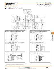
![PF Softstarter User manual [PDF] - Sprecher + Schuh](https://img.yumpu.com/48207512/1/190x245/pf-softstarter-user-manual-pdf-sprecher-schuh.jpg?quality=85)