PD01-29/15002-Mini Dynafile II - Dynabrade Inc.
PD01-29/15002-Mini Dynafile II - Dynabrade Inc.
PD01-29/15002-Mini Dynafile II - Dynabrade Inc.

You also want an ePaper? Increase the reach of your titles
YUMPU automatically turns print PDFs into web optimized ePapers that Google loves.
For Serial No. 1B1000 and Higher<br />
Parts Page Reorder No. <strong>PD01</strong>•<strong>29</strong><br />
Effective March, 2001<br />
Supercedes PD97•64<br />
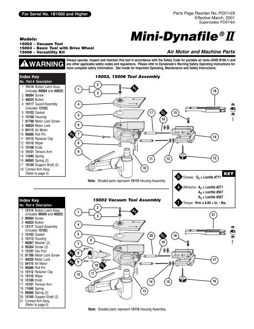
Models:<br />
<strong>Mini</strong>-<strong>Dynafile</strong> ® <strong>II</strong><br />
<strong>15002</strong> – Vacuum Tool<br />
15003 – Basic Tool with Drive Wheel<br />
15006 – Versatility Kit Air Motor and Machine Parts<br />
!<br />
Always operate, inspect and maintain this tool in accordance with the Safety Code for portable air tools (ANSI B186.1) and<br />
any other applicable safety codes and regulations. Please refer to <strong>Dynabrade</strong>’s Warning/Safety Operating Instructions for<br />
WARNING more complete safety information. See inside for Important Operating, Maintenance and Safety Instructions.<br />
Index Key<br />
No. Part # Description<br />
1 15114 Button Latch Assy.<br />
(includes 96084 and 40025)<br />
2 96084 Screw<br />
3 40025 Button<br />
4 15117 Guard Assembly<br />
(includes 15102)<br />
5 15102 Gasket<br />
6 15100 Housing<br />
7 01788 Motor Lock Screw<br />
8 400<strong>29</strong> Motor Lock<br />
9 04115 Air Motor<br />
10 96086 Roll Pin<br />
11 15112 Retainer Clip<br />
12 15110 Wiper<br />
13 15108 Knob<br />
14 15101 Tension Arm<br />
15 11040 Spring<br />
16 96085 Spring (2)<br />
17 15105 Support Shaft (2)<br />
18 Contact Arm Assy.<br />
(Refer to page 6)<br />
Index Key<br />
No. Part # Description<br />
1 15114 Button Latch Assy.<br />
(includes 96084 and 40025)<br />
2 96084 Screw<br />
3 40025 Button<br />
4 15117 Guard Assembly<br />
(includes 15102)<br />
5 15102 Gasket<br />
6 15113 Housing<br />
7 96087 Washer (2)<br />
8 95264 Screw (2)<br />
9 15107 Vac Port<br />
10 01788 Motor Lock Screw<br />
11 400<strong>29</strong> Motor Lock<br />
12 04115 Air Motor<br />
13 96086 Roll Pin<br />
14 15112 Retainer Clip<br />
15 15110 Wiper<br />
16 15108 Knob<br />
17 15101 Tension Arm<br />
18 11040 Spring<br />
19 96085 Spring (2)<br />
20 15105 Support Shaft (2)<br />
21 Contact Arm Assy.<br />
(Refer to page 6)<br />
1<br />
4<br />
15003, 15006 Tool Assembly<br />
2<br />
3<br />
G 2<br />
5<br />
6<br />
7<br />
17 G 2<br />
16<br />
15<br />
8<br />
9<br />
1<br />
4<br />
5<br />
7<br />
A 2 8<br />
A 9<br />
9<br />
12<br />
Note: Shaded parts represent 15115 Housing Assembly.<br />
6<br />
11<br />
A 2<br />
10<br />
<strong>15002</strong> Vacuum Tool Assembly<br />
2<br />
3<br />
10<br />
G 2<br />
Note: Shaded parts represent 15116 Housing Assembly.<br />
18<br />
14<br />
11 12 13<br />
A 2<br />
20 G 2 18<br />
13<br />
19<br />
G<br />
A<br />
T<br />
Grease: G 2 = Loctite #771<br />
Adhesive: A 2 = Loctite #271<br />
A 8 = Loctite #567<br />
A 9 = Loctite #587<br />
Torque: N•m x 8.85 = In. - lbs.<br />
21<br />
17<br />
14 15 16<br />
KEY
04115 Air Motor<br />
16<br />
2<br />
15 14 13 8 12<br />
10 8 7 5 3<br />
1<br />
26<br />
20 21 A 8 25<br />
30 32 34 36 38 40 A 8<br />
A 8 Left Hand Threads<br />
O 1 11<br />
9 6 4 T 28 N•m<br />
17<br />
18 T 45 N•m<br />
Right Hand Threads 22 23<br />
19<br />
24<br />
31 33 35 37 39 T 23 N•m<br />
27<br />
<strong>29</strong><br />
28<br />
41<br />
T<br />
O 1<br />
17 N•m<br />
Index Key<br />
No. Part # Description<br />
1 15118 Drive Wheel<br />
2 15106 Exhaust Cover<br />
3 15111 Silencer<br />
4 01580 Silencer<br />
5 02649 Bearing<br />
6 545<strong>29</strong> Shim Pak (3)<br />
7 01478 Front Bearing Plate<br />
8 50767 Pin (2)<br />
9 01479 Spacer<br />
10 01475 Rotor<br />
11 01480 Blades (4)<br />
12 01476 Cylinder<br />
13 02673 Rear Bearing Plate<br />
14 02696 Bearing<br />
15 02679 Shield<br />
16 01546 Housing<br />
17 01548 Gasket<br />
18 01461 Lock Nut<br />
19 01558 Collar<br />
20 95523 O-Ring<br />
21 01470 Insert<br />
22 01448 Throttle Lever<br />
01462 Safety Lock Lever<br />
23 12132 Pin<br />
24 95558 Retaining Ring<br />
25 02116 Housing - <strong>15002</strong><br />
02117 Housing - 15003<br />
26 01449 Valve Stem<br />
27 95730 O-Ring<br />
28 01024 O-Ring<br />
<strong>29</strong> 01469 Speed Regulator<br />
Assembly<br />
30 01464 Seal<br />
31 01472 Tip Valve<br />
32 01468 Spring<br />
33 01378 Air Control Ring<br />
34 95711 Retaining Ring<br />
35 01486 Felt Silencer (4)<br />
36 01379 Bronze Muffler<br />
37 96065 O-Ring<br />
38 01446 Air Deflector<br />
39 95620 Retaining Ring<br />
40 01578 Inlet Adapter<br />
41 94535 Muffler Assembly<br />
O<br />
Oil: O 1 = Air Lube<br />
KEY<br />
A<br />
T<br />
Adhesive: A 8 = Loctite #567<br />
Torque: N•m x 8.85 = In. - lbs.<br />
(<strong>PD01</strong>•<strong>29</strong>)<br />
2
Important Operating, Maintenance and Safety Instructions<br />
Carefully read all instructions before operating or servicing any <strong>Dynabrade</strong> ® Abrasive Power Tool.<br />
Warning: Hand, wrist and arm injury may result from repetitive work motion and overexposure to vibration.<br />
Important: All <strong>Dynabrade</strong> Rotary Vane air tools must be used with a Filter-Regulator-Lubricator to maintain all warranties.<br />
Operating Instructions:<br />
Warning: Eye, face, respiratory, sound and body protection must be worn while operating power tools. Failure to do so may result in serious injury or<br />
death. Follow safety procedures posted in workplace.<br />
1. With power source disconnected from tool, securely fasten abrasive/accessory on tool.<br />
2. Install air fitting into inlet bushing of tool. Important: Secure inlet bushing of tool with a wrench before attempting to install the air fitting to avoid<br />
damaging valve body housing.<br />
3. Connect power source to tool. Be careful not to depress throttle lever in the process.<br />
4. Check tool speed with tachometer. If tool is operating at a higher speed than the RPM marked on the tool or operating improperly, the tool should be<br />
serviced to correct the cause before use.<br />
Maintenance Instructions:<br />
1. Check tool speed regularly with a tachometer. If tool is operating at a higher speed than the RPM marked on the tool, the tool should be serviced to<br />
correct the cause before use.<br />
2. Some silencers on air tools may clog with use. Clean and replace as required.<br />
3. All <strong>Dynabrade</strong> Rotary Vane air motors should be lubricated. <strong>Dynabrade</strong> recommends one drop of air lube per minute for each 10 SCFM (example: if<br />
the tool specifications state 40 SCFM, set the drip rate of your filter-lubricator at 4 drops per minute). <strong>Dynabrade</strong> Air Lube (P/N 95842: 1pt. 473ml.)<br />
is recommended.<br />
4. An Air Line Filter-Regulator-Lubricator must be used with this air tool to maintain all warranties. <strong>Dynabrade</strong> recommends the following: 11405 Air Line<br />
Filter-Regulator-Lubricator — Provides accurate air pressure regulation, two-stage filtration of water contaminants and micro-mist lubrication of<br />
pneumatic components. Operates 40 SCFM @ 100 PSIG has 3/8" NPT female ports.<br />
5. Use only genuine <strong>Dynabrade</strong> replacement parts. To reorder replacement parts,please specify the Model #, Serial # and RPM of your machine.<br />
6. A Motor Tune-Up Kit (P/N 96074) is available which includes assorted parts to help maintain motor in peek operating condition. Please refer to<br />
<strong>Dynabrade</strong>'s Preventative Maintenance Schedule for a guide to expectant life of component parts.<br />
7. Mineral spirits are recommended when cleaning the tool and parts. Do not clean tool or parts with any solvents or oils containing acids, esters,<br />
keytones, chlorinated hydrocarbons or nitro carbons.<br />
Safety Instructions:<br />
Products offered by <strong>Dynabrade</strong> should not be converted or otherwise altered<br />
from original design without expressed written consent from <strong>Dynabrade</strong>, <strong>Inc</strong>.<br />
• Important: User of tool is responsible for following accepted safety codes such as those published by the American National Standards Institute (ANSI).<br />
• Operate machine for one minute before application to workpiece to determine if machine is working properly and safely before work begins.<br />
• Always disconnect power supply before changing abrasive/accessory or making machine adjustments.<br />
• Inspect abrasives/accessories for damage or defects prior to installation on tools.<br />
• Please refer to <strong>Dynabrade</strong>’s Warning/Safety Operating Instructions Tag (Reorder No. 95903) for more complete safety information.<br />
• Warning: Hand, wrist and arm injury may result from repetitive work, motion and overexposure to vibration.<br />
Notice<br />
All <strong>Dynabrade</strong> motors use the highest quality parts and metals available and are machined to exacting tolerances. The failure of quality pneumatic motors can<br />
most often be traced to an unclean air supply or the lack of lubrication. Air pressure easily forces dirt or water contained in the air supply into motor bearings<br />
causing early failure. It often scores the cylinder walls and the rotor blades resulting in limited efficiency and power. Our warranty obligation is contingent<br />
upon proper use of our tools and cannot apply to equipment which has been subjected to misuse such as unclean air, wet air or a lack of lubrication during the<br />
use of this tool.<br />
One Year Warranty<br />
Following the reasonable assumption that any inherent defect which might prevail in a product will become apparent to the user within one year from the date<br />
of purchase, all equipment of our manufacture is warranted against defects in workmanship and materials under normal use and service. We shall repair or<br />
replace at our factory, any equipment or part thereof which shall, within one year after delivery to the original purchaser, indicate upon our examination to<br />
have been defective. Our obligation is contingent upon proper use of <strong>Dynabrade</strong> tools in accordance with factory recommendations, instructions and safety<br />
practices. It shall not apply to equipment which has been subject to misuse, negligence, accident or tampering in any way so as to affect its normal<br />
performance. Normally wearable parts such as bearings, contact wheels, rotor blades, etc., are not covered under this warranty.<br />
Model Motor Motor Max. SFPM Sound Air Flow Rate Abrasive Belt Size Weight Length Height<br />
Number HP (W) RPM (SMPM) Level CFM/SCFM (LPM) <strong>Inc</strong>h (mm) Pound (kg) <strong>Inc</strong>h (mm) <strong>Inc</strong>h (mm)<br />
All Models .35 (261) 25,000 4,890 (1,486) 78 dB(A) 3/20 (566) 1/8"-1/2" (3-13)W x 12" (305)L 1.8 (.82) 10-3/4 (275) 3-1/2 (89)<br />
Additional Specifications: Air Inlet Thread 1/4" NPT • Hose I.D. Size 1/4" (8 mm) • 90 PSIG (6.2 Bars)<br />
3
Disassembly/Assembly Instructions - <strong>Mini</strong>-<strong>Dynafile</strong> ® <strong>II</strong><br />
Important: Manufacturer’s warranty is void if tool is disassembled before warranty expires.<br />
Notice: <strong>Dynabrade</strong> strongly recommends the use of their 52<strong>29</strong>6 Repair Collar (sold separately) during assembly/disassembly activities. Failure to<br />
use this collar will highly increase the risk of damage to the valve body of this tool. Please refer to parts breakdown for part identification.<br />
To Disassemble:<br />
1. Remove Belt Guard, abrasive belt and contact arm assembly.<br />
Motor Disassembly:<br />
1. Separate 04115 Air Motor from tool assembly (<strong>15002</strong>, 15003 or 15006) by loosening 01788 Motor lock screw with a 95266, 3 mm hex key.<br />
2. Hold 01546 Housing in a vise by using 52<strong>29</strong>6 Repair Collar or padded jaws.<br />
Note: Be careful not to over tighten vise which could damage 01546 Housing<br />
3. Use 50791 Lock Ring Wrench or an adjustable 3 mm pin wrench to remove the 15106 Exhaust Cover (turn counterclockwise). Remove Silencer.<br />
4. Pull motor assembly from housing.<br />
5. Fasten a bearing separator around the 01476 Cylinder (end nearest the 02673 Rear Bearing Plate).<br />
6. Place the bearing separator on the table of the 96232 Arbor press so that the motor spindle points toward the floor.<br />
7. Use a 3/16" diameter drive punch as a press tool and press the rear portion of the 01475 Rotor out of the 02696 Rear Bearing.<br />
8. With the motor now disassembled, secure 01475 Rotor in a soft aluminum or bronze jaw vise, and remove 15118 Drive Wheel with a 95262 14 mm<br />
Wrench or pipe wrench.<br />
9. Remove 01478 Front Bearing Plate, 02649 Front Bearing, shims and 01479 Spacer, these are a slip fit onto the rotor.<br />
10. Remove 02679 Shield from 02696 Rear Bearing, and press 02696 Rear Bearing from 02673 Rear Bearing Plate (96210 Bearing Removal<br />
Tool is available).<br />
Motor disassembly complete.<br />
Valve Body Disassembly:<br />
1. Position valve body in a vise by using 52<strong>29</strong>6 Repair collar so that air inlet points up..<br />
2. Secure 01578 Inlet Adapter with a wrench to prevent it from turning. While holding the inlet adapter stationary remove the air fitting by turning it counterclockwise.<br />
Important: 01578 inlet Adapter must be secured before attempting to remove the air fitting so as to avoid damaging the valve body housing.<br />
3. Remove 01578 inlet Adapter.<br />
4. Remove 95711 Retaining Ring from inlet adapter. Remove 01486 Felt Silencer (4), and 01379 Bronze Muffler.<br />
5. Remove 01564 Air Control Ring from the valve body housing. Use needle nose pliers and remove 01468 Spring, 01472 Tip Valve and 01464 Seal.<br />
6. Use a 2.5 mm drive punch to remove 12132 Pin and 01448 or 01462 Throttle Lever.<br />
7. Remove 95558 Retaining Ring and push 01469 Regulator from the valve body housing.<br />
Valve Body disassembly complete.<br />
Optional: To disassemble valve body from motor housing, peel back 01558 Collar to expose 01461 Lock Nut. Unscrew lock nut/valve body from motor<br />
housing (left hand thread).<br />
To Assemble:<br />
Important: Make sure parts are clean and in good condition before assembling.<br />
Motor Assembly:<br />
1. Place 01475 Rotor in soft aluminum or bronze jaw vise with threaded spindle pointing upwards.<br />
2. Slip 01479 Spacer onto rotor.<br />
3. Place a .002" shim into 01478 Front Bearing Plate as an initial spacing and slip 02649 Bearing into plate (Note: Shim Pak contains .001" and<br />
.002" shims.)<br />
4. Install bearing/bearing plate assembly onto rotor.<br />
5. Insert silencers into 15106 Exhaust Cover and slide over rotor.<br />
6. Tighten 15118 Drive Wheel onto Rotor (torque to 17 N•m/150 in. - lbs.).<br />
7. Check clearance between rotor and bearing plate by using a .001" feeler gauge. Clearance should be at .001" to .0015". Adjust clearance by repeating<br />
steps1-5 with different shim if necessary.<br />
8. Once proper rotor/gap clearance is achieved, install well lubricated 01480 Blades (4) into rotor slots. <strong>Dynabrade</strong> recommends their air lube P/N 95842.<br />
9. Install cylinder over rotor. Be sure air inlet holes of cylinder face away from bearing plate and that the 50767 Pin in the front bearing plate aligns<br />
correctly with the pin-hole in the cylinder.<br />
10. Press 02696 Rear Bearing into 02673 Rear Bearing Plate. Press bearing/bearing plate assembly onto rotor. Be sure that pin and air inlet holes line-up<br />
with pin slot and air inlet holes in cylinder. Important: Fit must be snug between bearing plates and cylinder. A loose fit will not achieve the proper<br />
preload of motor bearings. If too tight, rotor will not turn freely and must then be lightly tapped at press fit end so it will turn freely while still<br />
maintaining a snug fit.<br />
11. Apply a dab of grease onto 02673 Bearing and place 02679 Shield over 02673 Bearing.<br />
12. Secure housing in vise using 52<strong>29</strong>6 Repair Cover or padded jaws so motor cavity faces upwards.<br />
13. Install motor assembly into housing. Be sure motor drops all the way into housing.<br />
14. Tighten exhaust cover onto motor housing by using 50971 Lock Ring Wrench (torque 28 N•m/250 in. - lbs.).<br />
(<strong>PD01</strong>•<strong>29</strong>)<br />
4
Disassembly/Assembly Instructions - <strong>Mini</strong>-<strong>Dynafile</strong> ® <strong>II</strong> (continued)<br />
15. Motor adjustment can now be checked. With motor housing still mounted in vise, pull end of rotor and twist (10-15 lbs. force), rotor should turn<br />
freely without drag. If drag or rub is felt, then increase preload or remove shim. Also, push end of rotor and twist (10-15 lbs. force), rotor should<br />
turn freely without drag. If drag or rub is felt, then deload or add shim.<br />
Motor assembly is complete.<br />
Valve Body Assembly:<br />
1. Install 01469 Regulator complete with o-rings and valve stem into valve body housing. Secure it in place with 95558 Retaining Ring.<br />
2. Place valve body housing in a vise, holding it with the aid of 52<strong>29</strong>6 Repair collar so that the air inlet opening points up.<br />
3. Insert 01464 Seal into the air inlet opening so that it lays flat.<br />
4. Line up hole in valve stem with inlet opening in housing (looking past brass bushing). Install 01472 Tip Valve so that the metal pin passes through the<br />
hole in the valve stem. Install 01468 Spring (small end against tip valve).<br />
5. Position 01378 Air Control Ring around inlet opening. Place 01379 Bronze Muffler inside 01446 Air Deflector. With 95620 Retaining Ring installed on<br />
female threaded end of 01578 Inlet Adapter insert the inlet adapter through 01446 Air Deflector. Place 01486 Felt Silencer (4) inside 01446 Air<br />
Deflector. Install 95711 Retaining Ring into groove at the male threaded end of the inlet adapter. Install 96065 O-Ring into groove on the air deflector.<br />
6. Apply Loctite ® #567 (or equivalent) to the male threads of the 01578 Inlet adapter install 96065 O-Ring into groove on the air deflector.<br />
7. Install 01448 or 01462 Throttle Lever onto valve body housing with 12132 Pin.<br />
8. Secure 01578 Inlet Adapter with a wrench to prevent it from turning. While holding the inlet adapter stationary install the air fitting by turning it clock<br />
wise. Important: 01578 Inlet Adapter must be secured before attempting to install the air fitting so as to avoid damaging the valve body housing.<br />
Tool assembly is complete. Please allow 30 minutes for adhesives to cure before operating tool.<br />
Housing Assembly:<br />
1. With 400<strong>29</strong> Motor lock in place, install air motor assembly into housing and secure in place by tightening 01788 Motor Lock Screw.<br />
2. Complete assembly by installing contact arm assembly, abrasive belt and belt guard.<br />
Tool assembly is complete. Please allow 30 minutes for adhesives to cure before operating tool.<br />
Important: Motor should now be tested for proper operation at 90 PSIG. If motor does not operate properly or operates at a higher RPM than marked on<br />
the tool, the tool should be serviced to correct the cause before use.<br />
Note: Throttle lever is present at the factory at an 11:00 o’clock position.<br />
Important: The regular maintenance of any air tool will contribute to greater efficiency of tool and will prolong tool life. The failure of quality pneumatic air<br />
bearings causing early failure. It often scores the cylinder walls and the rotor blades resulting in limited efficiency and power. Frequent drainage of water<br />
traps in air lines is recommended. Each tool on each drop should also be equipped with a secondary air processing unit. This consists of an in-line<br />
Filter-Regulator-Lubricator. All <strong>Dynabrade</strong> Rotary Vane air tools must be used with a Filter-Regulator-Lubricator to maintain all warranties. Our warranty<br />
obligation is contingent upon proper use of our tools and cannot apply to equipment which has been subject to misuse such as unclean air, wet air or a lack<br />
of lubrication during the use of the tool.<br />
Loctite ® is a registered trademark of the Loctite Corp.<br />
Housing Angle Adjustment:<br />
1. Disconnect power source.<br />
2. To pivot housing, loosen 01788 Motor Lock Screw on housing with the supplied 3 mm hex wrench (P/N – 95266).<br />
3. Pivot housing to desired angle and retighten the 01788 Motor Lock Screw.<br />
Abrasive Belt/Contact Arm Change Instructions:<br />
To Change Belt:<br />
1. Disconnect power source.<br />
2. Remove “pop-off” cover.<br />
3. Pull back on tension arm assembly.<br />
4. Remove and replace abrasive belt and cover.<br />
5. Connect power source.<br />
6. Adjust belt tracking by turning 15108 Rough Adjustment Knob to the left or right accordingly while machine is running.<br />
To Change Contact Arm Assembly:<br />
1. Disconnect power source.motors can most often be traced to an unclean air supply or the lack of lubrication. Air pressure easily forces dirt or water<br />
contained in the air supply into motor.<br />
2. Remove “pop-off” cover.<br />
3. Pull back on tension arm assembly and remove abrasive belt.<br />
4. Remove 15108 Rough Adjustment Knob.<br />
5. Remove contact arm and replace with desired arm, making sure that the tab on the end of the arm is facing downward.<br />
6. Replace 15108 Knob.<br />
7. Install abrasive belt and cover.<br />
8. Connect power source and adjust belt tracking by turning 15108 Knob to the left or right accordingly while machine is running.<br />
5
<strong>Mini</strong>-<strong>Dynafile</strong> ® <strong>II</strong> Contact Arm Assemblies<br />
Contact Wheel Assembly <strong>Inc</strong>ludes wheel, bearing and shaft.<br />
Bearing<br />
Contact Wheel<br />
Bearing<br />
Contact Arm<br />
Shaft<br />
<strong>Mini</strong>-<strong>Dynafile</strong> ® <strong>II</strong> Standard Contact Arms<br />
Part Abrasive Contact Wheel Contact Wheel Contact Wheel Bearing<br />
Number Belt Size Description Assembly Only (2) Req. Shaft<br />
15026 1/2" x 12" 5/8" D x 3/8" W, Rubber 11078 11077 11052 11054<br />
15028 1/4" or 1/2" x 12" 1" D x 3/8" W, Rubber 11080 11079 11052 11054<br />
150<strong>29</strong> 1/8" x 12" 1" D x 3/8" W Urethane, Tapered 11086 11085 11052 11054<br />
15030 1/2" x 12" 5/16" D x 3/8" W, Steel 11068 11067 11051 11054<br />
15031 1/2" x 13" 7/16" D x 3/8" W, Rubber 11070 11069 11051 11054<br />
<strong>Mini</strong>-<strong>Dynafile</strong> ® <strong>II</strong> Contact Arms<br />
Contact arms allow for 3" workable reach.<br />
Contact Wheels noted include bearing and shaft.<br />
15026 (Standard on all models).<br />
Grind over contact wheel or platen.<br />
150<strong>29</strong><br />
Grind corners, enter grooves, strap polish.<br />
V-Tapered<br />
Belt Size: 1/2" wide x 12" long.<br />
11078 Contact Wheel: 5/8" diameter x 3/8" wide, rubber.<br />
11026 Platen: 1/2" wide.<br />
Belt Size: 1/8" wide x 12" long.<br />
11086 Contact Wheel: 1" diameter x 3/8" wide, urethane.<br />
No Platen<br />
15028<br />
Grind corners, enter grooves, strap polish.<br />
15030<br />
Enter channels as narrow as 7/16".<br />
45 PSIG Max.<br />
Belt Size: 1/4" or 1/2" wide x 12" long.<br />
11080 Contact Wheel: 1" diameter x 3/8" wide, rubber.<br />
No Platen<br />
Belt Size: 1/2" wide x 12" long.<br />
11068 Contact Wheel: 5/16" diameter x 3/8" wide, steel.<br />
11027 Platen: 1/2" wide.<br />
15031<br />
For 13" long belts<br />
Runs at 45 PSIG max.<br />
Work on contact wheel or Dynapad.<br />
Belt Size: 1/2" wide x 13" long.<br />
11070 Contact Wheel: 7/16" diameter x 3/8" wide, rubber.<br />
11027 Platen: 1/2" wide.<br />
(<strong>PD01</strong>•<strong>29</strong>)<br />
6
Optional Accessories<br />
Dynaswivel ®<br />
• Swivels 360˚ AT TWO PIVOT POINTS allowing the air<br />
hose to drop directly to the floor while providing superb<br />
tool handling.<br />
• New 94300 1/4" NPT, non-marring composite construction.<br />
96074 Motor Tune-Up Kit<br />
• <strong>Inc</strong>ludes assorted parts to help<br />
maintain and repair motor.<br />
Threaded Collet Inserts<br />
These uniquely designed inserts thread directly<br />
into the drive wheel.<br />
01644 – 1/4" insert<br />
01646 – 6 mm insert<br />
01647 – 1/8" insert<br />
01648 – 3 mm insert<br />
52<strong>29</strong>6 Repair Collar<br />
• Specially designed collar for use in vise to<br />
prevents damage to valve body of tool<br />
during disassembly/assembly.<br />
Abrasives<br />
12" Long Abrasive Belts<br />
Abrasive Impregnated Non-Woven Nylon<br />
Belt Super Fine Very Fine Medium Coarse<br />
Width Grey Blue Maroon Brown<br />
1/2" 90311 90312 90313 90314<br />
Aluminum Oxide<br />
Belt<br />
Grit<br />
Width 40 60 80 120 180 220 320<br />
1/8" –– –– 92206 92207 92208 92209 92210<br />
1/4" 92105 92106 92107 92108 92118 92119 92120<br />
1/2" 92110 92111 92112 92113 92114 92115 962116<br />
7
DYNABRADE ®<br />
Toll Free (U.S.A.) 1-800-828-7333<br />
Toll Free (Can.) 1-800-344-1488<br />
Visit Our Web Site: www.dynabrade.com<br />
Email: Customer.Service@<strong>Dynabrade</strong>.com<br />
DYNABRADE, INC., 8989 Sheridan Drive • Clarence, NY 14031-1490 • Phone: (716) 631-0100 • Fax: 716-631-2073 • International Fax: 716-631-2524<br />
DYNABRADE EUROPE S.àr.l., Zone Artisanale • L-5485 Wormeldange—Haut, Luxembourg • Telephone: 352 76 84 94 1 • Fax: 352 76 84 95 1<br />
© DYNABRADE, INC., 2001 PRINTED IN USA