DAMAGE PREDICTION OF BALL JOINTS IN ANTI-ROLL BARS
DAMAGE PREDICTION OF BALL JOINTS IN ANTI-ROLL BARS
DAMAGE PREDICTION OF BALL JOINTS IN ANTI-ROLL BARS
You also want an ePaper? Increase the reach of your titles
YUMPU automatically turns print PDFs into web optimized ePapers that Google loves.
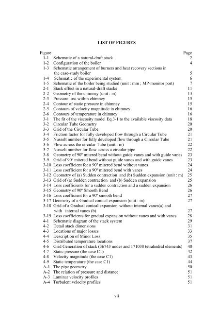
LIST <strong>OF</strong> FIGURES<br />
Figure<br />
Page<br />
1-1 Schematic of a natural-draft stack 2<br />
1-2 Configuration of the boiler 4<br />
1-3 Schematic arrangement of burners and heat recovery sections in<br />
the case-study boiler 5<br />
1-4 Schematic of the experimental system 6<br />
1-5 Schematic of the boiler being studied (unit : mm ; MP-monitor port) 7<br />
2-1 Stack effect in a natural-draft stacks 11<br />
2-2 Geometry of the chimney (unit : m) 13<br />
2-3 Pressure loss within chimney 15<br />
2-4 Contour of static pressure in chimney 15<br />
2-5 Contours of velocity magnitude in chimney 16<br />
2-6 Contours of temperature in chimney 16<br />
3-1 The fit of the viscosity model Eq.3-1 to the available viscosity data 18<br />
3-2 Circular Tube Geometry 20<br />
3-3 Grid of the Circular Tube 20<br />
3-4 Friction factor for fully developed flow through a Circular Tube 21<br />
3-5 Nusselt number for fully developed flow through a Circular Tube 21<br />
3-6 Flow across the circular Tube (unit : m) 22<br />
3-7 Nusselt number for flow across a circular pipe 22<br />
3-8 Geometry of 90º mitered bend without guide vanes and with guide vanes 23<br />
3-9 Grid of 90º mitered bend without guide vanes and with guide vanes 23<br />
3-10 Loss coefficient for a 90º mitered bend without vanes 24<br />
3-11 Loss coefficient for a 90º mitered bend with vanes 24<br />
3-12 Geometry of (a) Sudden contraction and (b) Sudden expansion (unit : m) 25<br />
3-13 Grid of (a) Sudden contraction and (b) Sudden expansion 25<br />
3-14 Loss coefficients for a sudden contraction and a sudden expansion 26<br />
3-15 Geometry of 90º Smooth Bend 26<br />
3-16 Loss coefficient for a 90º smooth bend 27<br />
3-17 Geometry of a Gradual conical expansion (unit : m) 27<br />
3-18 Grid of a Gradual conical expansion without internal vanes(a) and<br />
with internal vanes (b) 27<br />
3-19 Loss coefficients for gradual expansion without vanes and with vanes 28<br />
4-1 Schematic diagram of the stack system 29<br />
4-2 Detail stack dimensions 31<br />
4-3 Locations of major losses 33<br />
4-4 Description of Minor Loss 35<br />
4-5 Distributed temperature locations 37<br />
4-6 Grid Generation of stack (36743 nodes and 171038 tetrahedral elements) 40<br />
4-7 Static pressure (the case C1) 42<br />
4-8 Velocity magnitude (the case C1) 43<br />
4-9 Static temperature (the case C1) 44<br />
A-1 The pipe geometry 50<br />
A-2 The relation of pressure and distance 51<br />
A-3 Laminar velocity profiles 51<br />
A-4 Turbulent velocity profiles 51<br />
vii


