DAMAGE PREDICTION OF BALL JOINTS IN ANTI-ROLL BARS
DAMAGE PREDICTION OF BALL JOINTS IN ANTI-ROLL BARS
DAMAGE PREDICTION OF BALL JOINTS IN ANTI-ROLL BARS

You also want an ePaper? Increase the reach of your titles
YUMPU automatically turns print PDFs into web optimized ePapers that Google loves.
69<br />
0.1<br />
Friction Factor<br />
XL=1.25<br />
XL=1.5<br />
0.01<br />
100 1000 10000 100000 1000000 10000000<br />
Reynolds Number<br />
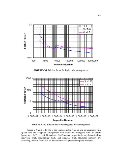
FIGURE C-9 Friction factor for in-line tube arrangement<br />
1000<br />
XL=1.25<br />
XL=1.5<br />
Friction Factor<br />
100<br />
10<br />
1<br />
1.00E+02 1.00E+03 1.00E+04 1.00E+05 1.00E+06 1.00E+07<br />
Reynolds Number<br />
FIGURE C-10 Friction factor for staggered tube arrangement<br />
Figure C-9 and C-10 show the friction factor f for in-line arrangement with<br />
square tube and staggered arrangement with equilateral triangular tube. In theses<br />
figures x T = S T /D, x L = S L /D, and x D = S’ L /D denote, respectively, the dimensionless<br />
transverse pitch, longitudinal pitch, and diagonal pitch. Reynolds numbers are<br />
increasing, friction factor will be decrease because pressure drop are increased.