Download - British Electric Flight Association
Download - British Electric Flight Association
Download - British Electric Flight Association

Create successful ePaper yourself
Turn your PDF publications into a flip-book with our unique Google optimized e-Paper software.
Not wanting to write an article on this (I have far too much to do and too little time<br />
already), I decided to respond to Peter directly and include the text in the ‘Letters<br />
to the Editor’ feature.<br />
I appreciate your concerns, but they are unfounded when using a balancing<br />
charger or external balancer. There is no need to perform any soldering or<br />
change pack connections to achieve balanced charging. Hopefully the following<br />
will explain it properly.<br />
Firstly, the limiting voltage for a 3S pack should be 12.6V (4.2V/cell) and<br />
therefore 13V should never be seen. If a LiPo charger is at 13V when set for 3S<br />
there is a serious safety fault with it and it should not be used.<br />
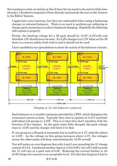
I have modified your spreadsheet to show the action of the balancer circuits.<br />
16<br />
Charging at 5A with balancers connected<br />
Each balancer is a variable resistance provided by a FET, which dissipates the<br />
unwanted current as heat. Typically they start to operate at 4.21V and limit<br />
individual cell groups to 4.25V. This is so that they don't interfere with the<br />
function of the charger. As the pack nears fully charged, the pack voltage<br />
rises to 12.6V and the charger will limit it to that.<br />
If one group on a 3S pack is extremely low it could be at 4.1V, with the others<br />
at 4.25V. As the voltage on this group increases above 4.1V, the voltages<br />
across the other packs will drop, maintaining the 12.6V overall.<br />
You will notice on your diagram that cells 4 and 5 are exceeding the 1C charge<br />
current of 2.5A. I produced another chart at 4.5A (0.9C), but cell 5 still exceeds<br />
the 1C cell rate at a pack rate of 0.8C. Reducing the current further to 4A<br />
(0.8C) drops the current to an acceptable level. For this last diagram I had to<br />
E.F.-U.K.