CKD series ABSODEX direct drive actuators - BIBUS Kft
CKD series ABSODEX direct drive actuators - BIBUS Kft
CKD series ABSODEX direct drive actuators - BIBUS Kft

Create successful ePaper yourself
Turn your PDF publications into a flip-book with our unique Google optimized e-Paper software.
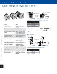
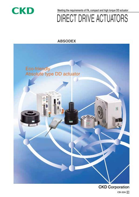
Meeting the requirements of FA, compact and high torque DD actuator<br />
DIRECT DRIVE ACTUATORS<br />
<strong>ABSODEX</strong><br />
Eco-friendly<br />
Absolute type DD actuator<br />
CB-32A 2
Eco-friendly, intelligent index units comptible with<br />
different networks.<br />
High precision/high performance<br />
Combining 360˚ flexible index, intermittent revolution and<br />
continuous rotation, high precision absolute DD actuator is<br />
available now.<br />
High Flexibility & Intelligence<br />
Eco-friendly function<br />
Energy and space savings, oil free and reuse,<br />
etc., environmentally friendly production<br />
equipment can be built.<br />
Network function<br />
One-touch connecting serial transmission<br />
slave station allows easy connection to<br />
different networks.
CC-Link<br />
DeviceNet<br />
Serial transmission<br />
slave station<br />
High precision/<br />
high performance<br />
Return to origin not required<br />
An absolute resolver that<br />
recognizes the current position is<br />
used without returning to origin.<br />
Easy operation<br />
Index time can be set <strong>direct</strong>ly per<br />
0.01 second increment.<br />
Dedicating <strong>drive</strong>r<br />
H type: high performance<br />
S type: small/high performance<br />
GH type: high performance compatible type<br />
GS type: small and high performance compatible type<br />
Body actuator<br />
Dialog terminal<br />
Handy type<br />
Easy programming<br />
5 <strong>series</strong> available according to applications<br />
AX1000 <strong>series</strong><br />
AX2000 <strong>series</strong> convertible AX2000G <strong>series</strong><br />
AX4000 <strong>series</strong> convertible AX4000G <strong>series</strong><br />
AX5000 <strong>series</strong><br />
AX8000 <strong>series</strong><br />
Compact/high torque<br />
No torque down even in high<br />
speed range.<br />
(Excluding some models)<br />
High precision positioning<br />
Maintaining high resolution;<br />
540672 pulses per rotation, high<br />
precision index is enabled.<br />
(Repeatability of index: ±5 ").<br />
Easy installation and centering<br />
Socket and spigot for mounting<br />
and thread hole are installed on<br />
rotational and fixed sections.<br />
Integrated wiring is achieved by<br />
hollow shaft.<br />
Smooth cam curve <strong>drive</strong><br />
Cam curve of modified sine (MS),<br />
modified trapezoidal (MT),<br />
deformation constant velocity (MC,<br />
MC2) and tropecoid (TR) can be<br />
selected for different applications.<br />
Dust proof structure<br />
Sealing applied on rotational<br />
section of actuator (excluding<br />
some models)<br />
(AX8000 <strong>series</strong> is IP65<br />
conformed.)<br />
System configuration<br />
Eco-friendly function<br />
Energy saving<br />
Electric power is consumed during<br />
index, while no power is<br />
consumed during dewll time.<br />
Change and waste of lubricant is not required.<br />
Troublesome lubricant change and<br />
waste of oil are not required.<br />
No pollution by oil leakage.<br />
To reduce equipment size<br />
by space saving body.<br />
Origin detection sensor, reducer<br />
and motor, etc., are not required.<br />
Easy change of specifications<br />
and reuse is possible.<br />
Specifications can be changed by<br />
dialog terminal or PC, etc., also,<br />
reuse is possible, while difficult for<br />
mechanical index.<br />
Network function<br />
Open network compatible<br />
Compatible with 2 types of open<br />
network; CC-Link and DeviceNet<br />
Reducing wiring cost<br />
Drastic reduced wiring enables<br />
reduction of wiring man-hours.<br />
Compatibility<br />
AX2000G·<br />
AX4000G <strong>series</strong><br />
Driver, actuator and cable are<br />
compatible. Flexible combination<br />
achieves easy maintenance and<br />
control.
Features<br />
Return to origin not required<br />
Integrating an absolute resolver that recognizes the current position<br />
when power turned on in the <strong>direct</strong> <strong>drive</strong> actuator, troublesome<br />
origin search operation is not required. Also, restart can<br />
be done from the current position after emergency stop.<br />
Direct <strong>drive</strong> actuator resolver consists of 2 sets. One uses R/D conversion to<br />
split the sine waveform detected every 2.7˚ (360˚/132) rotation angle into<br />
4096. The other splits 360˚ into 4096 to detect the absolute position on 360˚.<br />
No sensor for searching for the origin need to be used as with incremental<br />
method.<br />
The position information is recognized when power supply turned on, so back<br />
up memory is not required. This system has the reliable detection mechanism.<br />
Hollow<br />
Output shaft<br />
Cover (provided for some models)<br />
Stator (coil)<br />
Rotor (magnet)<br />
Absolute resolver<br />
High precision<br />
High resolution; 540672 pulses per rotation<br />
Index accuracy: ±15" (second), while ±30" (second) for AX3000<br />
and AX4000 <strong>series</strong>.<br />
Repeat positioning accuracy: ±5 " (second) *<br />
*1 " (second) = 1˚/3600<br />
Example of index accuracy measurement (with brake)<br />
Model no.<br />
Load table<br />
Moving time<br />
Index number<br />
Measuring<br />
device<br />
sec.<br />
HEIDENHAIN,<br />
Germany<br />
Example of index accuracy measurement (without brake)<br />
Model no.<br />
Load table<br />
Moving time<br />
Index number<br />
Measuring<br />
device<br />
sec.<br />
HEIDENHAIN,<br />
Germany<br />
High torque<br />
Using PM type motor appropriate for indexing, this DD motor<br />
has excellent torque characteristics without torque-down even<br />
in high speed range.<br />
Torque-rotational speed characteristics<br />
(If motor volume is equivalent.)<br />
Continuous power area<br />
Short-time rating area<br />
Continuous power area<br />
Rotational speed<br />
(rpm)<br />
Rotational speed<br />
(rpm)<br />
Torque<br />
PM type (permanent-magnet type)<br />
Torque<br />
VR type (variable reluctance type)<br />
Space saving<br />
Compact and space saving <strong>direct</strong> <strong>drive</strong> actuator compared to<br />
circular table with [motor + reducer]<br />
Intro 3
Features<br />
Smooth cam curve <strong>drive</strong> realized<br />
5 types * of cam curve are provided as standard. Shock is<br />
suppressed to the minimum when moving or stopped.<br />
* modified sine (MS), modified trapezoidal (MT), deformation<br />
constant velocity (MC and MC2) and tropecid (TR)<br />
Four cam curves with the operating features below can be<br />
selected with parameters. This enables smooth transfer<br />
positioning not possible with simple acceleration/deceleration<br />
time setting control.<br />
Easy design<br />
Providing socket and spigot on fixing side of the body and<br />
table, easy centering is achieved.<br />
Easy connection<br />
Integration of <strong>drive</strong>r and controller reduces man-hour of<br />
connection.<br />
Flexible programming<br />
NC language enables positioning on the required point. Also,<br />
NC programs, up to 256 programs, can be stored in the<br />
<strong>drive</strong>r.<br />
Great variety of external interfaces<br />
Program input, parameter setting and reading of inner state,<br />
etc., are allowed by RS-232C serial communication.<br />
Also, M code, etc., great variety of external interfaces, are<br />
available to connect to the PLC.<br />
Using serial transmission slave stations, 2 types of open<br />
network; CC-Link and Device-Net are also available.<br />
Easy programming<br />
An equal index program is created by interactively inputting<br />
the number of divisions and movement time, etc., with this<br />
dialog terminal (optional). This enables quick startup after the<br />
system is installed.<br />
Complex operations are set by creating programs in NC<br />
language.<br />
Driver program storage capacity is approximate 6000<br />
characters maximum (256 programs). The use of Windows’<br />
communication software [Teaching note] allows a user to<br />
create and save programs with PC.<br />
CE marking<br />
CE marking products (option) conformed to the Low Voltage<br />
Directive and EMC Directive are available. Refer to the<br />
instruction manual for installation, etc., to conforming to<br />
standards.<br />
Refer to " <strong>CKD</strong> European standards conforming products<br />
guide " for details of applicable models and conformity<br />
standards.<br />
Characteristics and measuring examples of cam curve<br />
(MS)<br />
(MT)<br />
(MC)<br />
(TR)<br />
Name Acceleration Measuring example<br />
Modified sine<br />
Modified trapezoidal<br />
Modified constant velocity<br />
Tropecoid<br />
Speed<br />
Acceleration<br />
Speed<br />
Acceleration<br />
Speed<br />
Acceleration<br />
Speed<br />
Acceleration<br />
Working conditions of above example<br />
Model no.<br />
AX1045<br />
Operating conditions Index angle 90˚<br />
Index time 0.5 sec.<br />
Load moment of inertia 1.67 x 10 -2 kg·m 2<br />
Large diameter hollow (AX4000 and AX4000G <strong>series</strong>)<br />
This large hollow diameter specifications allow easy piping<br />
and wiring on dial plate. If a ball spline is installed, the product<br />
can be used for axis of a P & P unit for small parts conveyance.<br />
(Consult with <strong>CKD</strong> for ball spline installation)<br />
Non-backrush model with negative actuation electromagnetic<br />
brake (option) is also available. (AX4000 and AX4000G<br />
<strong>series</strong>).<br />
Brake integrated type (AX5000 and AX8000 <strong>series</strong>)<br />
Integrated a pneumatic brake, the output shaft is clamped<br />
when stopped to increase holding rigidity.<br />
• Available for works that torque is applied to the table<br />
• Fine rotary vibration of table by servo is suppressed.<br />
• Holding torque more than the maximum output torque of<br />
actuator is provided.<br />
(At 0.5MPa)<br />
Low Voltage Directive<br />
EN60034-1, EN60034-5, EN50178<br />
EMC Directive<br />
EN55011, EN61800-3, EN-61000-3-2, EN61000-3-3<br />
Certificating body<br />
TÜV Rheinland<br />
Optional dowel hole to positioning is available.<br />
Optional movable cable is available for cable bending<br />
applications.<br />
High grade dust proof/waterproof (AX8000 <strong>series</strong>)<br />
IEC60529 standards IP65* conforming<br />
TÜV Rheinland certifications<br />
Higher grade water proof is achieved by air purge.<br />
*When performing an air purge, supply a dry clean compressed air with low pressure<br />
(0.05MPa).<br />
Intro 4
Direct <strong>drive</strong> motor compatible type <strong>series</strong> variation<br />
Series<br />
6<br />
12<br />
18<br />
Torque (N·m)<br />
22<br />
45<br />
75<br />
AX2000G <strong>series</strong><br />
AX2006G<br />
AX2012G<br />
AX2018G<br />
Available <strong>drive</strong>r Actuator<br />
AX4000G <strong>series</strong><br />
GS type <strong>drive</strong>r<br />
AX4022G<br />
AX4045G<br />
AX4075G<br />
GH type <strong>drive</strong>r<br />
Not available<br />
Intro 5
Serial transmission<br />
slave station<br />
Examples of applications ... Intro 10<br />
Precautions ... Intro 13<br />
Related parts model no. table ... Page 71<br />
Selection guide ... Page 73<br />
Torque (N·m)<br />
150 300<br />
500<br />
Index accuracy<br />
(sec.)<br />
Repeat accuracy<br />
(sec.)<br />
Features<br />
Applications<br />
Page<br />
AX2000G<br />
±30<br />
±5<br />
• High speed revolution<br />
(300rpm)<br />
• Compact with small<br />
diameter<br />
• Large hollow diameter<br />
(ø30)<br />
• P & P<br />
• Turntable<br />
• Assembly machine<br />
1<br />
to<br />
6<br />
AX4000G<br />
AX1000<br />
AX4150G<br />
AX4300G<br />
AX4500G<br />
±30<br />
±5<br />
• High speed revolution<br />
(AX4022GS,<br />
AX4045GS: 240rpm<br />
and AX4075GS:<br />
140rpm)<br />
• For large moment of<br />
inertia load<br />
(AX4150GH,<br />
AX4300GH and<br />
AX4500GH)<br />
• Large hollow diameter<br />
and great variety of<br />
size options<br />
• Turntable<br />
• Inspection machine<br />
• Assembly machine<br />
• P & P<br />
7<br />
to<br />
18<br />
AX2000<br />
AX4000<br />
Not available<br />
A single type of <strong>drive</strong>r can handle all size of <strong>actuators</strong>.<br />
Equipped a controller function, a NC program can handle turning angle,<br />
moving time and timer, etc., of an actuator flexibly. Also, using M code<br />
output, communication to the external PLC is possible.<br />
GS type<br />
57<br />
58<br />
61<br />
GH type<br />
59<br />
to<br />
61<br />
AX5000<br />
AX8000<br />
Driver<br />
Option<br />
Intro 6
Direct <strong>drive</strong> actuator <strong>series</strong> variation<br />
Series<br />
6<br />
9<br />
12<br />
Torque (N·m)<br />
22(21)<br />
45(42)<br />
75(70)<br />
AX1000 <strong>series</strong><br />
AX1022<br />
AX1045<br />
AX1075<br />
AX2000 <strong>series</strong><br />
AX2006<br />
AX2012<br />
AX2021<br />
AX2042<br />
Available <strong>drive</strong>r Actuator<br />
AX4000 <strong>series</strong><br />
AX5000 <strong>series</strong><br />
AX8000 <strong>series</strong><br />
S type <strong>drive</strong>r<br />
AX4009<br />
AX4022<br />
AX5022<br />
AX4045<br />
AX5045<br />
AX8045<br />
AX4075<br />
AX5075<br />
AX8070<br />
H type <strong>drive</strong>r<br />
Small and high performance S type <strong>drive</strong>r is recommended.<br />
CE marking conformable products: Refer to [<strong>CKD</strong> European standards conforming products guide (catalog no.CC-543)].<br />
AX1000, AX2000, AX4000 and AX5000 <strong>series</strong><br />
S and H type <strong>drive</strong>rs<br />
Intro 7
Serial transmission<br />
slave station<br />
Examples of applications ... Intro 10<br />
Precautions ... Intro 13<br />
Related parts model no. table ... Page 71<br />
Selection guide ... Page 73<br />
Torque (N·m)<br />
150 210 300<br />
AX1150 AX1210<br />
500<br />
Index accuracy Repeat accuracy<br />
(sec.) (sec.)<br />
±15<br />
±15<br />
±5<br />
±5<br />
Features<br />
High precision<br />
specifications; index<br />
accuracy and run out of<br />
output shaft, etc.<br />
• Compact with small<br />
diameter (AX2006 and<br />
AX2012)<br />
• Easy cable wiring and<br />
piping due to hallow<br />
fixed shaft<br />
(AX2021 and AX2042)<br />
Applications<br />
• Precision measuring<br />
• Turntable<br />
• Inspection machine<br />
• Assembly machine<br />
• Turntable<br />
• P & P<br />
• Assembly machine<br />
Page<br />
19<br />
to<br />
24<br />
25<br />
to<br />
30<br />
AX2000G<br />
AX4000G<br />
AX1000<br />
±30<br />
±5<br />
• Large hollow diameter<br />
and great variety of<br />
size options<br />
• Maximum output<br />
torque 9 to 500 N·m<br />
7 models are available.<br />
• Turntable<br />
• Inspection machine<br />
• Assembly machine<br />
• P & P<br />
31<br />
to<br />
40<br />
AX2000<br />
AX4150<br />
AX4300<br />
AX4500<br />
AX5150<br />
AX5210<br />
±15<br />
±5<br />
• A pneumatic brake is<br />
integrated to clamp an<br />
output shaft when<br />
stopped.<br />
• Appropriate for a work<br />
that load applied after<br />
stop.<br />
• Precision measuring<br />
• Turntable<br />
• Inspection machine<br />
• Assembly machine (pressfit)<br />
41<br />
to<br />
47<br />
AX4000<br />
±15<br />
±5<br />
• IP65 conformity<br />
(IEC standards)<br />
• Appropriate for rotary<br />
positioning equipment in<br />
machining or cleaning<br />
process, or in the<br />
environment containing a<br />
lot of powder dust<br />
• Machining and<br />
grinding such as<br />
light cutting, etc.<br />
• Turntable<br />
Note. Refer to Page 53<br />
for precautions.<br />
49<br />
to<br />
53<br />
AX5000<br />
AX8000<br />
Not available<br />
Equipped a controller function in a <strong>drive</strong>r, a NC program<br />
allows turning angle and moving time timer, etc., of an<br />
actuator to be set flexibly.<br />
Also, communication to external PLC is allowed using M<br />
code output.<br />
S type<br />
57<br />
58<br />
61<br />
H type<br />
59<br />
to<br />
61<br />
Driver<br />
Option<br />
Intro 8
MODEL: AX9***H<br />
SERIAL: *******<br />
<strong>CKD</strong> Corpor<br />
poration<br />
<strong>ABSODEX</strong><br />
MADE IN JAPANAN<br />
AX Series<br />
System configuration<br />
Basic settings<br />
1. Input a program from PC or dialog terminal.<br />
2. Set the required parameters in the same manner.<br />
3. Set gain as adequate.<br />
Basic driving method<br />
1. Select the program to run from PLC.<br />
2. Input the start signal from PLC.<br />
3. The positioning complete signal is outputted from the <strong>drive</strong>r<br />
after <strong>drive</strong>n.<br />
Direct <strong>drive</strong> actuator<br />
Actuator body<br />
Cable set (standard 4m)<br />
(Motor cable)<br />
(Resolver cable)<br />
Driver body<br />
10A<br />
<strong>ABSODEX</strong><br />
DRIVER H TYPE<br />
MON.<br />
POWER<br />
Dialog terminal<br />
[AX0170H] (separate sales)<br />
PC<br />
3-200V AC<br />
FG<br />
Noise filter<br />
Noise filter for<br />
motor cable<br />
• If cable length is 6m<br />
and over, install the<br />
noise filter for motor<br />
cable.<br />
POWER<br />
AC180-220V<br />
50/60HZ<br />
@CR@<br />
<strong>ABSODEX</strong><br />
10A<br />
10A<br />
R<br />
S<br />
T<br />
FG<br />
U<br />
V<br />
W<br />
BK+<br />
BK-<br />
CN2<br />
G1<br />
G2<br />
CN1 CN3<br />
I/O used<br />
Network<br />
used<br />
RS-232C<br />
I/O connector (MR-50LM)<br />
I/O<br />
AX-OPX<br />
AX <strong>drive</strong>r power supply<br />
24V DC<br />
PLC<br />
Master<br />
Remote I/O station<br />
Slave unit power supply<br />
AX <strong>drive</strong>r power supply<br />
24V DC<br />
Computer communication software<br />
[Teaching note] Windows software (free)<br />
RS-232C cable for communication (2m)<br />
[AX-RS232C-9P] for D-sub 9 pin<br />
(Separate sales)<br />
PLC<br />
Configuration<br />
Standard<br />
Name<br />
Quantity<br />
Actuator body<br />
1<br />
Driver body (controller attached)<br />
1<br />
Cable set (4m)<br />
1<br />
Accessory: I/O connector (MR-50LM) and fuse (10A and AC250V)<br />
Driver bracket<br />
Note: Fuse is not included in accessory of GS and S type <strong>drive</strong>rs.<br />
Programming tool<br />
• [AX0170H] is available as programming terminal for S and H<br />
type <strong>drive</strong>rs.<br />
• Computer communication software [Teaching note] is<br />
available. (Free software for Windows).<br />
Programming, parameter setting and sending operation commands,<br />
etc. to a <strong>direct</strong> <strong>drive</strong> actuator are done from PC. It is<br />
possible to save the programs.<br />
RS-232C interface cable is required.<br />
a) for D-sub 25 pin (2m) (model no.: AX-RS232C-25P)<br />
b) for D-sub 9 pin (2m) (model no.: AX-RS232C-9P)<br />
c) for 14 pin half pitch (2m) (model no.: AX-RS232C-14P)<br />
Intro 9
AX Series<br />
Applications<br />
E.g. 1. index unit for rotary table type automatic machine<br />
• Creating programs of process A and B, and switching these<br />
programs, two different workpieces can be processed by a<br />
single piece of equipment.<br />
A<br />
B<br />
A<br />
B<br />
A<br />
[Merit of <strong>direct</strong> <strong>drive</strong> actuator]<br />
B<br />
B<br />
• Used an absolute resolver, no origin detection sensor is<br />
required.<br />
A<br />
• Equal index programs are easily inputted by a dialog terminal.<br />
• Index number (or angle) and moving time (or maximum<br />
rotational speed), etc. are merely inputted to program.<br />
E.g. 2.<br />
axis of P & P unit<br />
• Putting a ball spline through hollow, the unit can be used as<br />
an intelligent P & P unit.<br />
[Merit of ABODE]<br />
• Used an absolute resolver, the actuator will not return to the<br />
origin even when power turned on, so can move <strong>direct</strong>ly in the<br />
either position.<br />
*When installing the product in mechanism or equipment, care<br />
must be taken.<br />
(Refer to Intro 12 for cautions [Design & selection] (6).)<br />
Ball spline<br />
E.g. 3. small parts inspection equipment<br />
Survey instrument<br />
• It is appropriate for equipment that picks up a workpiece with air<br />
blow using hollow.<br />
Air blow<br />
E.g. 4. rotation and conveyance of large panel<br />
• It is appropriate for transferring and rotating large panels.<br />
Note. Even if the limit of allowable load moment of inertia is<br />
reached, the product may be used depended with<br />
adjustment of parameters, etc. Consult with <strong>CKD</strong> for details.<br />
Intro 10
AX Series<br />
Applications 1<br />
Operation specifications 1 (operation of index unit)<br />
Operation specifications<br />
4 Index (90˚ equal index)<br />
Moving time 0.5 sec.<br />
Shift 1 index counterclockwise every start input from PLC.<br />
Move 90˚ in<br />
0.5 second<br />
Example of program<br />
Main program<br />
O1;<br />
Use program number [1].<br />
G11;<br />
Set time (sec.) for unit of F of NC code.<br />
G10\ 1A4;<br />
Divid one rotation into 4 sides.<br />
G91.1;<br />
Set incremental dimension.<br />
A0\ F0\ .5;<br />
Move to the nearest index station in 0.5 second.<br />
N1M0\;<br />
Wait start signal input from PLC.<br />
A-1F0\ 5;<br />
Move an index in 0.5 second.<br />
J1;<br />
Jump to the block of sequence number 1.<br />
M30\ ;<br />
Program end<br />
(Note) When using dialog terminal or teaching note, no descriptions are required since O1 is automatically set by inputting program number 1.<br />
Example of PLC actuating signal<br />
Initial process: process executed once at first<br />
Process name<br />
I/O signal name<br />
PLC output<br />
PLC input<br />
Remarks<br />
1 Program number selection<br />
· Number selection 0 bit<br />
· Number selection 1 bit<br />
· Number selection 2 bits<br />
· Number selection 3 bits<br />
· Number setting the first digit<br />
Selecting program number 1.<br />
(Select the program to run. In<br />
this example, no. 1 is used.)<br />
2 Return process · Start signal<br />
· Positioning complete signal<br />
· Start input waiting output<br />
Return process complete by<br />
positioning complete signal<br />
Index process: process executed per index.<br />
Process name<br />
I/O signal name<br />
PLC output<br />
PLC input<br />
Remarks<br />
3 Index treatment<br />
· Start signal<br />
· Positioning complete signal<br />
· Start input waiting output<br />
Index complete by positioning<br />
complete signal<br />
(Note) Program number selection and start signals must be inputted when start input waiting output turned on.<br />
Intro 11
Operation specifications 2 (operation of oscillator unit)<br />
AX Series<br />
Applications 2<br />
0˚<br />
Operation specifications<br />
Move -45˚ 45˚ repeatedly every start input from PLC.<br />
Moving time 0.7 sec.<br />
Brake is activated when stopped. (Note 1)<br />
Emergency stop input is to be effective. (Note 2)<br />
-45˚<br />
45˚<br />
Direct <strong>drive</strong> actuator<br />
Example of program<br />
Main program<br />
O2;<br />
G10\ 5;<br />
G11;<br />
G90\ ;<br />
N1M69;<br />
A45F0\ .7;<br />
M68;<br />
M0\ ;<br />
M69;<br />
A-45F0\ .7;<br />
M68;<br />
M0\ ;<br />
J1;<br />
M30\ ;<br />
Use a program number [2].<br />
Set an angle(˚) for unit of A of NC code.<br />
Set a time (sec.) for unit of F of NC code.<br />
Absolute dimension<br />
Brake release<br />
Move until 45˚ position in 0.7 second<br />
Brake operation<br />
Waiting start input from PLC<br />
Brake release<br />
Move until 45˚ position in 0.7 second<br />
Brake operation<br />
Wait start input from PLC.<br />
Jump to block of sequence number 1<br />
Program end<br />
Note 1: Use a <strong>direct</strong> <strong>drive</strong> actuator with brake.<br />
If optional electromagnetic brake is used, refer to [control method of Electromagnetic brake].<br />
Note 2: If emergency stop is inputted during brake operation, the brake is activated after reset.<br />
When the start signal is inputted continuously without re-selecting a program number, release<br />
the brake by brake release input after reset, then input the first start signal.<br />
Brake release input<br />
Start input<br />
Positioning complete output<br />
100msec and over<br />
Intro 12
Safety precautions<br />
When designing and manufacturing equipment using a <strong>direct</strong> <strong>drive</strong> actuator, the manufacturer is obligated to check that the<br />
safety of mechanism, and entire systems including electric controls are secured.<br />
It is important to select, use, handle or maintain the product appropriately to ensure that <strong>CKD</strong> products be used safely.<br />
To ensure the safety of equipment, always observe warnings and cautions.<br />
Danger<br />
1 High voltage is applied to the gland on <strong>drive</strong>r front panel. Do not touch the gland during energized.<br />
Do not touch the gland approximately for 5 minutes immediately after power supply turned off, since<br />
high voltage is applied, while the charge stored in inner capacitor is discharged.<br />
2 When removing a frame side cover for maintenance and inspection, and switch replacement in <strong>drive</strong>r,<br />
etc., always turn power off since a risk of electric shock with high voltage could be created.<br />
3 Do not install and remove a connector, etc. while power turned on, or malfunction, failure or electric<br />
shock may be caused.<br />
Warning<br />
1 Use the product within the specification range.<br />
1 If of uses out of specifications or special applications, consult with <strong>CKD</strong> for the availability.<br />
2 The use out of specification range may prevent the product from attaining its functions, and the safety is not secured.<br />
3 The use will be limited in special applications or in special environment. Secure the safety for entire equipment.<br />
2 Each handling explanation and cautions of the product must be observed to prevent accidents.<br />
1 Do not rotate an actuator output shaft more than 30 rpm when power turned off.<br />
The electricity generated by actuator may result in <strong>drive</strong>r fault or create a hazard of electric shock.<br />
2 If servo-off (including emergency stop and alarm) and brake off are done with torque applied by gravity, etc., the<br />
output shaft will rotate by torque.<br />
These operations must be done with balanced without torque, or after safety is checked.<br />
3 Sufficient care must be taken not to put a hand on the output shaft since an uncontrolled motion could occur during<br />
gain adjustment stage and trial runs. Also, when operating the actuator from the position where the actuator can not<br />
be seen, check that the safety is secured, even if the output shaft is rotated, before operation.<br />
4 The brake of actuator does not always hold the position of output shaft thoroughly.<br />
When doing maintenance, while unbalanced load is applied and output shaft could rotate, it is not safe if the position<br />
is held by the brake only. Please keep the load with balanced, or provide a mechanical interlock.<br />
3 The product is designed and manufactured as a part for general industrial machines.<br />
Therefore, the person that has sufficient knowledge and experience must handle the product.<br />
4 For the safety on equipment design, corporate standards and regulation, etc., must be observed.<br />
5 Do not remove components before confirming safety.<br />
6 When restarting machine and equipment, check if countermeasures are taken not to remove installations,<br />
then perform the work.<br />
Safety cautions are ranked as [DANGER], [WARNING] and [CAUTION] in this section.<br />
DANGER:<br />
When a dangerous situation may occur, or when there is high urgency to a<br />
warning, leading to fatal or serious injuries, if handling is mistaken.<br />
WARNING: When a dangerous situation may occur, leading to fatal or serious injuries, if<br />
handling is mistaken.<br />
CAUTION: When a dangerous situation may occur, leading to minor injuries or physical<br />
damage, if handling is mistaken.<br />
Note that some items described as [CAUTION] may lead to serious results depending on the<br />
situation. In any case, the important description that must be observed is listed.<br />
Intro 13
Caution<br />
When exporting<br />
[Direct <strong>drive</strong> actuator] is subject to [foreign exchange and trade control laws]. Therefore, when exporting <strong>direct</strong> <strong>drive</strong><br />
<strong>actuators</strong> from Japan, an approval of Japanese government is required.<br />
Caution<br />
Design & selection<br />
1 Actuators (excluding AX8000 <strong>series</strong>) and <strong>drive</strong>rs are not water<br />
proof. When using these products in the environment where<br />
water and oil will contact to the products, take countermeasures<br />
of water proof.<br />
2 Adhesions of swarf and dust, etc., on the actuator and <strong>drive</strong>r<br />
may result in possible leakage of electricity and failures. Please<br />
avoid these adhesions.<br />
3 The cable attached as standard can not be used with repeatedly<br />
bent. Select an optional movable cable.<br />
4 If the cable length is longer than standard (4m), insert a noise<br />
filter on the motor cable. Connect the IN side of noise filter on<br />
the <strong>drive</strong>r side, then install the filter near the <strong>drive</strong>r as close as<br />
possible.<br />
8 If rigidity of machinery and equipment is not satisfactory, install<br />
a dummy inertia at the closest place to the actuator to reduce<br />
resonance of machinery and equipment.<br />
If of output shaft extension, as reference, the diameter of<br />
extended shaft is<br />
ø60mm and over if of AX * 006, AX * 009, AX * 012, AX *<br />
018, AX * 022 and AX * 045, ø90mm and over if of AX *<br />
075, AX * 150, AX * 210 and AX * 300, while ø150mm and<br />
over if of AX * 500.<br />
As reference, the size of dummy inertia is [load inertia] X (0.2<br />
to 1). [Fig. 3].<br />
[Fig. 3] Example 1, dummy inertia installation<br />
Model no.<br />
LF-310KA<br />
LF-320KA<br />
Maker<br />
NEC TOKIN (stock)<br />
NEC TOKIN (stock)<br />
AX * * 75 or less<br />
AX * 150 and over<br />
3-10A<br />
3-20A<br />
Dummy inertia<br />
5 If power and servo are turned OFF with servo turned ON (holding<br />
state), unless applying external force, the output shaft may<br />
move from the holding position.<br />
6 An optional electromagnetic brake is usually used to increase<br />
holding rigidity when the output shaft stopped.<br />
Do not use the brake to stop the rotating output shaft.<br />
7 The machine and equipment in which <strong>direct</strong> <strong>drive</strong> actuator is<br />
installed should be rigid enough to realize maximum <strong>direct</strong><br />
<strong>drive</strong> actuator performance. If load equipment or the frame's<br />
mechanical vibration is relatively low (200 to 300 Hz or less),<br />
resonance could occur in the <strong>direct</strong> <strong>drive</strong> actuator and load<br />
equipment or frame. Fix rotary table and main unit mounting<br />
bolts to ensure sufficient rigidity without loosening [Fig. 1].<br />
[Fig. 1] fixing of actuator<br />
Dial plate fixing<br />
Dummy inertia = [load inertia] X (0.5 to 2), if of connection by<br />
gears and spline, or by key.<br />
If speed changes with belts or gears, use load inertia with<br />
actuator output shaft converted, and install a dummy<br />
inertia on the actuator.<br />
[Fig. 4] [Fig. 5]<br />
(Caution) Install a dummy inertia as large as possible<br />
according to performance of the actuator.<br />
[Fig. 4] Example 2, dummy inertia installation<br />
Mounting base<br />
Dummy inertia<br />
Gear<br />
Also, gain adjustment is required depended with magnitude of<br />
load table.<br />
Even if a <strong>direct</strong> <strong>drive</strong> actuator can not be installed on the machine<br />
<strong>direct</strong>ly, install the actuator on a frame with sufficient<br />
rigidity. [Fig. 2].<br />
[Fig. 2] installation of actuator<br />
[Fig. 5] Example 3, dummy inertia installation<br />
Ball spline<br />
Dummy inertia<br />
Intro 14
MODEL: AX9***H<br />
SERIAL: *******<br />
<strong>CKD</strong> Corporation<br />
<strong>ABSODEX</strong><br />
MADE IN JAPAN<br />
Labor saving mechanisms warnings and cautions to secure safety<br />
Always read this section before starting use.<br />
Caution<br />
9 Brake connection method<br />
Pneumatic brake<br />
Design & selection<br />
Resolver cable (standard 4m)<br />
(Motor cable)<br />
Direct <strong>drive</strong> actuator<br />
Actuator body<br />
Driver body<br />
10A<br />
<strong>ABSODEX</strong><br />
DRIVER H TYPE<br />
MON.<br />
POWER<br />
3-200V AC<br />
Noise filter<br />
POWER<br />
AC180-220V<br />
50/60HZ<br />
10A<br />
10A<br />
R<br />
S<br />
T<br />
G1<br />
G2<br />
CN1<br />
CN2<br />
CN3<br />
FG<br />
FG<br />
U<br />
V<br />
W<br />
BK+<br />
BK-<br />
Noise filter for motor cable<br />
· If cable length is 6m and<br />
over, install the noise filter<br />
for motor cable.<br />
1) A valve for pneumatic brake is integrated in the <strong>direct</strong> <strong>drive</strong> actuator body.<br />
Supply 24VDC to the external power input (1, 2 - 3, 4 pin) of I/O connector (CN3) as power supply for the valve.<br />
2) Supply clean compressed air of 0.5MPa to the joint for brake. Do not lubricate with a lubricator, etc.<br />
3) The integrated brake merely increases the holding rigidity when the output shaft is stopped. Do not brake the output shaft, while the shaft is<br />
rotating.<br />
Recommended air circuit for pneumatic brake<br />
Direct <strong>drive</strong> actuator integrated<br />
Clamp mechanism<br />
Air dryer<br />
Air filter<br />
5µm<br />
Regulator<br />
0.5MPa<br />
Intro 15
MODEL: AX9***H<br />
SERIAL: *******<br />
<strong>CKD</strong> Corpor<br />
poration<br />
<strong>ABSODEX</strong><br />
MADE IN JAPANAN<br />
Caution<br />
Electromagnetic brake<br />
Design & selection<br />
Direct <strong>drive</strong> actuator<br />
Actuator body<br />
Cable set (standard 4m)<br />
(Resolver cable)<br />
Blue color lead wire<br />
(Not polarized)<br />
Protection element<br />
(Actuator body attached)<br />
3-200V AC<br />
FG<br />
(Motor cable)<br />
Noise filter<br />
POWER<br />
AC180-220V<br />
50/60HZ<br />
@CR@<br />
<strong>ABSODEX</strong><br />
Driver body<br />
10A<br />
10A<br />
10A<br />
<strong>ABSODEX</strong><br />
DRIVER H TYPE<br />
MON.<br />
G1<br />
G2<br />
CN1<br />
POWER<br />
CN2<br />
CN3<br />
24V DC<br />
Relay<br />
Noise filter for motor cable<br />
· If cable length is 6m and<br />
over, install the noise<br />
filter for motor cable.<br />
1) Do not use the electromagnetic brake to brake or stop the output shaft, while the shaft is rotating.<br />
2) If BK+ and BK- of the <strong>drive</strong>r, and electromagnetic brakes are <strong>direct</strong>ly connected, the <strong>drive</strong>r may be damaged.<br />
3) When connecting the inductive load such as the following relay, etc., to the external contact, use a coil with rated voltage 24VDC and rated<br />
current 100mA or less, and take countermeasures for surge.<br />
4) When using an electromagnetic brake, supply 24VDC to the external power input (1, 2 - 3, 4 pin) of I/O connector (CN3).<br />
Recommended circuit for electromagnetic brake<br />
Electromagnetic brake<br />
External power 24V DC<br />
(User's preparation)<br />
Protection element<br />
Attached to<br />
( )<br />
actuator body<br />
Electromagnetic brake lead wire<br />
(Blue approximate 30cm)<br />
CR<br />
External power 24V DC<br />
(User's preparation)<br />
External contact (relay, etc.)<br />
(User's preparation)<br />
CN3<br />
BK+<br />
BK-<br />
BK-<br />
Driver<br />
Surge countermeasures (diode, etc.)<br />
(User's preparation)<br />
Operation method<br />
1. Control by NC program (M68/M69)<br />
When running "M68" code, it is de-energized (brake operation)<br />
between BK+ and BK-, or when running "M69" code, it is energized<br />
(brake release) between BK+ and BK-.<br />
2. Control by brake release input (I/O connector, 18 pin)<br />
When inputting brake release with brake applied, it is energized<br />
(brake release) between BK+ and BK-.<br />
If an electromagnetic brake applies frequently (ON-OFF cycle), use a<br />
solid state relay (SSR) for an external contact.<br />
Recommended model G3NA-D210B DC5-24 (OMRON)<br />
Read the instruction manual of SSR carefully before starting use.<br />
· For relay contact serial connection<br />
Electromagnetic brake<br />
Protection element<br />
Attached to<br />
( )<br />
actuator body<br />
External power 24V DC<br />
(User's preparation)<br />
Relay (4 poles)<br />
(User's preparation)<br />
CR<br />
Electromagnetic brake lead wire<br />
(Blue approximate 30cm)<br />
External power 24V DC<br />
(User's preparation)<br />
CN3<br />
BK+<br />
R<br />
S<br />
T<br />
FG<br />
U<br />
V<br />
W<br />
BK+<br />
BK-<br />
Driver<br />
Surge countermeasures (diode, etc.)<br />
(User's preparation)<br />
Use a relay whose contact capacity is 10-fold larger than rated current.<br />
Otherwise, use multi-pole relays connecting in serial. The life of relay<br />
will be longer.<br />
10 When using a product with electromagnetic brake while putting the shaft<br />
through the hollow, use non magnetic materials (SUS303, etc.)<br />
The use of a magnetic material (S45C, etc.) allows the shaft to be<br />
magnetized, this may affect peripheral devices adversely, or iron powder<br />
may be attracted onto the device.<br />
11 Care must be taken since the magnetized part near electromagnetic<br />
brake may attract iron powder, etc., and affect instruments, sensors and<br />
other components adversely.<br />
Intro 16
Labor saving mechanisms warnings and cautions to secure safety<br />
Always read this section before starting use.<br />
Caution<br />
Installation & adjustment<br />
1 Use an actuator and a <strong>drive</strong>r having the same serial number<br />
combination. After opening the package, confirm that actuator,<br />
<strong>drive</strong>r, and cable serial numbers are the same. When using<br />
several <strong>direct</strong> <strong>drive</strong> actuator units together, check that unlike<br />
units are not combined. Combining unlike actuator and <strong>drive</strong>r<br />
may cause incorrect operation and faults.<br />
2 Connect the actuator and <strong>drive</strong>r only with the enclosed cable.<br />
Check that excessive force is not applied and that the cable is<br />
not damaged. Do not change the length or material of the<br />
enclosed cable, because this may cause malfunctions or faults.<br />
3 Check that the correct power supply is connected. Connecting<br />
a non-designated power supply could cause faults. Wait at<br />
least 5 seconds after turning power OFF before turning it ON<br />
again.<br />
4 Fix the <strong>direct</strong> <strong>drive</strong> actuator securely to the machine, and install<br />
loads such as the table before adjusting gain. Confirm that no<br />
interference exists and that the state is safe even when<br />
movable sections are rotated.<br />
5 Do not tap the output shaft with a hammer nor assemble it<br />
forcibly. Doing so may prevent expected accuracy and<br />
functions from being realized and could cause faults.<br />
6 Avoid placing the actuator near strong magnetic fields such as<br />
rare-earth magnets. Doing so may prevent maintenance of the<br />
expected accuracy.<br />
7 The temperature of the actuator body will be high depended with<br />
working conditions. Provide a protective cover, etc., not to touch<br />
the body.<br />
8 Do not do machining such as boring, etc., on the actuator body.<br />
If machining is required, consult with <strong>CKD</strong>.<br />
9 Do not step on the actuator or a movable part such as dial<br />
plate, etc., installed on the actuator for maintenance work, etc.<br />
10 Compatible type (AX * * * * GS and AX * * * * GH) can not be<br />
connected to conventional actuator body and <strong>drive</strong>r AX * * * * S<br />
and AX * * * * H.<br />
11 About compatible type (AX * * * * GS and AX * * * * GH)<br />
• A wrong combination of actuator and <strong>drive</strong>r will give Alarm 3<br />
after program input (after parameter setting). The combination<br />
of actuator and <strong>drive</strong>r must be checked.<br />
Note: Alarm 3 appears to prevent malfunction if the actuator<br />
and <strong>drive</strong>r combination differ from when the program<br />
was input. Alarm 3 is reset when the program and<br />
parameters are input again.<br />
• If operation is started with an incorrect actuator and <strong>drive</strong>r<br />
combination after the program is input (after parameters are<br />
set), a malfunction could occur or equipment could be<br />
damaged.<br />
• When changing cable length and type, a discrete cable must<br />
be ordered.<br />
Caution<br />
Usage & maintenance<br />
1 Do not disassemble the actuator. Doing so may compromise<br />
expected functions or accuracy. Attempting to disassemble the<br />
resolver could critically damage it.<br />
2 When testing withstand voltage of a machine or equipment in<br />
which <strong>direct</strong> <strong>drive</strong> actuator is assembled, disconnect the main<br />
power cable (L1, L2, L3) or (R, S, T) from the <strong>direct</strong> <strong>drive</strong><br />
actuator <strong>drive</strong>r and check that voltage is not applied to the<br />
<strong>drive</strong>r itself. Failure to do so may cause faults.<br />
3 If alarm "4" (actuator overload: electronic thermal) occurs, wait<br />
for actuator temperature to drop sufficiently before restarting.<br />
Possible causes of alarm[4] could be as following. Eliminate<br />
causes, then use the product again.<br />
• caused by resonance/vibration —> installation rigidity be<br />
secured sufficiently.<br />
• caused by tact time/speed —> moving time/dwell time be<br />
extended.<br />
• caused by structure that constricts output shaft —> M68 and<br />
M69 commands be added.<br />
Intro 17
Warranty<br />
Conditions related to the warranty term and scope are as follows:<br />
Warranty<br />
1. Warranty term<br />
1 year after delivery. One day of operation is assumed to be within 8 hours. If use is exceeded within 1 year, the warranty shall terminate<br />
at that point.<br />
Durability (Direct <strong>drive</strong> actuator)<br />
10,000,000 times for <strong>direct</strong> <strong>drive</strong> actuator brakes with air brakes, piston packing, and valve. Conditions: room temperature, room humidity,<br />
rated voltage, rated pneumatic pressure<br />
2. Scope of warranty<br />
If any faults found to be the responsibility of <strong>CKD</strong> occur within the above warranty term, the faulty part shall be repaired immediately by<br />
<strong>CKD</strong> free of charge.<br />
Note that the following faults are excluded from the warranty term:<br />
1 Faults due to use exceeding conditions and environments in product specifications.<br />
2 Faults caused by careless or incorrect handling or improper control.<br />
3 Fault causes by factors other than those to delivered parts.<br />
4 Faults caused by improper use of the product.<br />
5 Faults due to modifications to product structure, performance, or specifications by a party other than <strong>CKD</strong> after the product is<br />
delivered, or faults caused by repairs not designated by <strong>CKD</strong>.<br />
6 When using this product in the user's machine or equipment, damage that can be avoided if the user's machines or equipment have<br />
the functions and structure, etc., considered normal within the industry.<br />
7 Faults caused by matters that could not be predicted with the technology applied when the product was delivered.<br />
8 Faults caused by fire, earthquake, flood, lightning, force de majeure, acts of God, pollution, salt, gas, abnormal voltage, or other<br />
external factors.<br />
The warranty here refers to that of the actually delivered product, and does not include damage caused by a fault in the delivered product.<br />
3. Warranty when exporting to a foreign country<br />
(1) Products returned to the <strong>CKD</strong> plant or to a company or plant designated by <strong>CKD</strong> shall be repaired. All work and expenses related to<br />
return shall be excluded from compensation.<br />
(2) The repaired product shall be returned to a designated place in Japan with domestic packaging specifications<br />
This warranty specifies basic conditions. If warranty details given in individual specification drawings or specifications differ from these<br />
warranty conditions, specification drawings or specifications shall take priority.<br />
Intro 18
Direct <strong>drive</strong> actuator compatible type<br />
AX2000G Series<br />
Compatibility flexibly combined with <strong>drive</strong>r, actuator and cable<br />
High speed revolution (maximum rotational speed 300rpm), compact<br />
with small diameter and large hollow diameter (ø30)<br />
Maximum torque: 6/12/18 N•m<br />
Available <strong>drive</strong>r: GS type <strong>drive</strong>r<br />
Actuator specifications<br />
Descriptions<br />
AX2006G<br />
AX2012G<br />
AX2018G<br />
Maximum output torque<br />
N·m<br />
6.0<br />
12.0<br />
18.0<br />
Continuous power torque<br />
N·m<br />
2.0<br />
4.0<br />
6.0<br />
Maximum rotational speed<br />
rpm<br />
300<br />
Allowable axial load<br />
N<br />
1000<br />
Allowable moment load<br />
N·m<br />
40<br />
Output shaft moment of inertia<br />
kg·m 2<br />
0.00575<br />
0.00695<br />
0.00910<br />
Allowable load moment of inertia<br />
kg·m 2<br />
0.3<br />
0.4<br />
0.5<br />
Index accuracy<br />
sec.<br />
±30<br />
Repeatability<br />
sec.<br />
±5<br />
Output shaft friction torque<br />
N·m<br />
0.6<br />
0.7<br />
Resolver resolution<br />
P/rev<br />
540672<br />
Motor insulation grade<br />
Class F<br />
Motor withstanding voltage<br />
1500V AC for 1 minute<br />
Motor insulation resistance<br />
10MΩ and over 500V DC<br />
Ambient temperature range<br />
0 to 45 ˚C<br />
Ambient humidity range<br />
20 to 85%RH to be no dew condensation.<br />
Conservation ambient temperature range<br />
-20 to 80 ˚C<br />
Conservation ambient humidity range<br />
20 to 90%RH to be no dew condensation.<br />
Mass<br />
kg<br />
4.7<br />
5.8<br />
7.5<br />
Run out of output shaft<br />
mm<br />
0.03<br />
Surface run out of output shaft<br />
mm<br />
0.03<br />
Maximum speed/torque characteristics<br />
AX2006G<br />
[rpm]<br />
350<br />
AX2012G<br />
AX2018G<br />
(Note) moment load<br />
300<br />
L<br />
F<br />
250<br />
F<br />
200<br />
L<br />
150<br />
100<br />
50<br />
0<br />
0<br />
5 10 15 20<br />
[N·m]<br />
(Fig. a)<br />
(Fig. b)<br />
M (N·m) =F (N) X L (m)<br />
M: moment load<br />
F: load<br />
L: distance from output<br />
shaft center<br />
M (N·m) =F (N) X (L+0.02) (m)<br />
M: moment load<br />
F: load<br />
L: distance from output shaft<br />
flange plane<br />
Always read precautions on Intro 13 to 18 before starting use.
How to order<br />
AX2000G Series<br />
How to order<br />
AX2<br />
Model<br />
018<br />
Options<br />
GS B D08 J1<br />
P1<br />
S<br />
AX2000G<br />
Series<br />
G Body surface treatment<br />
Note 3<br />
Symbol<br />
Content<br />
Actuator<br />
A<br />
Size<br />
(Maximum torque)<br />
A<br />
Size (maximum torque)<br />
006<br />
012<br />
018<br />
6 N·m<br />
12 N·m<br />
18 N·m<br />
B<br />
Available <strong>drive</strong>r<br />
C<br />
Mounting base<br />
Note 3 and 4<br />
D<br />
Cable change<br />
Note 2<br />
B Available <strong>drive</strong>r<br />
GS With GS type <strong>drive</strong>r<br />
C Mounting base (can not use with dowel holes P2 and P3.)<br />
Blank Standard (without mounting base)<br />
B With blackening mounting base<br />
BS Electroless nickel plating surface treatment mounting base<br />
Be used with body surface treatment S.<br />
D Cable change<br />
Blank<br />
D * *<br />
DM * *<br />
Standard (cable length 4m)<br />
Cable length change<br />
Movable cable length change<br />
* * cable length<br />
02 2m<br />
Blank 4m<br />
06 6m<br />
08 8m<br />
10 10m<br />
15 15m<br />
20 20m<br />
(Note)-DM<br />
[Note]<br />
If cable length is 6m and<br />
over, use the noise filter<br />
for motor cable.<br />
Note on model no. selection<br />
Note 1: Select a <strong>drive</strong>r according to the following table.<br />
Driver power supply voltage table<br />
Available GS type compatible <strong>drive</strong>r<br />
<strong>drive</strong>r<br />
Model<br />
AX2006G<br />
AX2012G<br />
AX2018G<br />
3-200V AC<br />
to 230V AC<br />
Blank<br />
Blank<br />
Blank<br />
1-100V AC<br />
to 115V AC<br />
J1<br />
J1<br />
J1<br />
E<br />
Available <strong>drive</strong>r<br />
Power supply voltage<br />
Note 1<br />
F Dowel hole<br />
Note 4<br />
E Driver power supply voltage<br />
Refer to the <strong>drive</strong>r power supply voltage table on the left.<br />
F Dowel hole (Note 5)<br />
Blank Standard (without dowel hole)<br />
P1 Top 1 piece<br />
P2 Bottom 1 piece<br />
P3 Both top and bottom sides 1 piece each<br />
G Body surface treatment<br />
Blank Standard (blackening treatment)<br />
S Electroless nickel plating treatment<br />
Note 2: If the cable is bended repeatedly, use an optional movable cable.<br />
Refer to Page 3 for dimensions of the cable.<br />
Note 3: Specify body surface and mounting base treatments in both sections C and G .<br />
Note 4: If section C mounting base is "B"; blackening mounting base or "BS";<br />
electroless nickel plating surface treatment, "P2" and "P3" can not be selected.<br />
Note 5: No surface treatment may be provided for additionally machined section.<br />
*When ordering a discrete part for maintenance, consult with <strong>CKD</strong>.
AX2000G Series<br />
Cable specifications<br />
Cable dimensions<br />
Cable minimum bending radius<br />
Standard cable<br />
Movable cable<br />
(15)<br />
(15)<br />
(20)<br />
(22)<br />
(300)<br />
L (standard length 4m)<br />
Resolver cable<br />
Motor cable<br />
100<br />
41<br />
18<br />
48<br />
Resolver<br />
Cable<br />
Motor<br />
Cable<br />
50mm<br />
100mm<br />
60mm<br />
110mm<br />
Precautions<br />
If cable length is 6m and over, use the noise filter for motor cable (near <strong>drive</strong>r).<br />
When connecting a motor cable to the <strong>drive</strong>r, care must be taken to connect them correctly with matching the mark tube on<br />
cable and the mark on <strong>drive</strong>r.<br />
If the cable is bended repeatedly, use a movable cable (option).<br />
Also when using the movable cable, fix the cable sheath section near the actuator body connector.<br />
When selecting movable cable option, the movable cable is used between the <strong>drive</strong>r and actuator connector, while standard<br />
cable is used for the body extended line between the actuator body and connector. The body extended cable must be fixed at<br />
the place not moved.<br />
When connecting the cable, insert a connector certainly in deep inside. Also, set screws of a connector must be tightened<br />
certainly.<br />
Care must be taken not to pull the body extended cable.<br />
Modification such as cut and extension of a cable, etc., must not be done, or failure and malfunction may be caused.
AX2000G Series<br />
Dimensions<br />
Dimensions<br />
AX2006G<br />
0.04<br />
A<br />
Mounting base (option)<br />
ø5H7 depth 8 (option)<br />
4-ø7<br />
AX2000G<br />
Fixed section<br />
95<br />
50<br />
6-M5 depth 10 (equal)<br />
For dial plate mounting<br />
Actuator<br />
P.C.D.100<br />
95<br />
Rotational section<br />
(5)<br />
ø110<br />
ø90h7<br />
ø30.5<br />
(Fixed shaft I.D.)<br />
A<br />
43.5<br />
(ø30H8 range)<br />
3.5<br />
1<br />
100<br />
95<br />
90<br />
Body extended cable length 500mm (not movable cable)<br />
110<br />
Caution: The minimum<br />
bending range of cable<br />
outlet is 20mm.<br />
45˚<br />
4<br />
ø30H8<br />
(Fixed shaft I.D.)<br />
ø40<br />
(Option base I.D.)<br />
ø80h8<br />
ø150<br />
30<br />
12.5<br />
Fixed section<br />
B<br />
4-M6 depth 12 (equal)<br />
P.C.D.60<br />
ø6H7 depth 8 (option)<br />
0.04 B<br />
40.5 X 21<br />
19.5<br />
28<br />
Fixed section<br />
Caution: When using<br />
the movable cable, fix<br />
the cable sheath top.<br />
Recommended position of<br />
connector through hole for<br />
motor mounting base<br />
22<br />
Cable position<br />
AX center<br />
Cable length<br />
standard 4m<br />
35<br />
42
AX2000G Series<br />
Dimensions<br />
AX2012G<br />
0.04<br />
A<br />
Mounting base (option)<br />
ø5H7 depth 8 (option)<br />
4-ø7<br />
Fixed section<br />
95<br />
50<br />
6-M5 depth 10 (equal)<br />
For dial plate mounting<br />
P.C.D.100<br />
95<br />
Rotational section<br />
(5)<br />
ø110<br />
ø90h7<br />
ø30.5<br />
(Fixed shaft I.D.)<br />
A<br />
Body extended cable length 500mm (not movable cable)<br />
43.5<br />
(ø30H8 range)<br />
3.5<br />
1<br />
110<br />
115<br />
110<br />
120<br />
Caution: The minimum<br />
bending range of cable<br />
outlet is 20mm.<br />
45˚<br />
4<br />
ø30H8<br />
(Fixed shaft I.D.)<br />
ø40<br />
(Option base I.D.)<br />
ø80h8<br />
ø150<br />
30<br />
12.5<br />
Fixed section<br />
B<br />
4-M6 depth 12 (equal)<br />
P.C.D.60<br />
ø6H7 depth 8 (option)<br />
0.04 B<br />
40.5 X 21<br />
19.5<br />
28<br />
Fixed section<br />
Caution: When using the<br />
movable cable, fix the<br />
cable sheath top.<br />
Recommended connector<br />
through hole for motor<br />
mounting base<br />
22<br />
Cable position<br />
AX center<br />
<br />
Cable length<br />
standard 4m<br />
35<br />
42
AX2000G Series<br />
Dimensions<br />
Dimensions<br />
AX2018G<br />
0.04<br />
A<br />
Mounting base (option)<br />
ø5H7 depth 8 (option)<br />
4-ø7<br />
AX2000G<br />
Fixed section<br />
95<br />
50<br />
6-M5 depth 10 (equal)<br />
For dial plate mounting<br />
Actuator<br />
P.C.D.100<br />
Rotational section<br />
(5)<br />
95<br />
ø110<br />
ø90h7<br />
ø30.5<br />
(Fixed shaft I.D.)<br />
A<br />
43.5<br />
(ø30H8 range)<br />
3.5<br />
Body extended cable length 500mm (not movable cable)<br />
110<br />
1<br />
150<br />
145<br />
155<br />
Caution: The minimum<br />
bending range of cable<br />
port is 20mm.<br />
45˚<br />
4<br />
ø30H8<br />
(Fixed shaft I.D)<br />
ø40<br />
(Option base I.D.)<br />
ø80h8<br />
ø150<br />
30<br />
12.5<br />
Fixed section<br />
B<br />
4-M6 depth 12 (equal)<br />
P.C.D.60<br />
ø6H7 depth 8 (option)<br />
0.04 B<br />
40.5 X 21<br />
19.5<br />
28<br />
Fixed section<br />
Caution: When using<br />
the movable cable, fix<br />
the cable sheath top.<br />
Recommended position of<br />
connector through hole for<br />
motor mounting base<br />
22<br />
Cable position<br />
AX center<br />
Cable length<br />
standard 4m<br />
35<br />
42
Direct <strong>drive</strong> actuator compatible type<br />
AX4000G Series<br />
Compatibility flexibly combined with <strong>drive</strong>r, actuator and cable<br />
High speed revolution (maximum rotational speed: AX4022GS, AX4045GS; 240rpm, AX4075GS;<br />
140rpm) large hollow diameter for easy cable wiring and piping, and great variety of options<br />
Maximum torque: 22/45/75 N• m<br />
Available <strong>drive</strong>r: GS type <strong>drive</strong>r<br />
Actuator specifications<br />
Descriptions<br />
AX4022G<br />
AX4045G<br />
AX4075G<br />
Maximum output torque<br />
N·m<br />
22<br />
45<br />
75<br />
Continuous power torque<br />
N·m<br />
7<br />
15<br />
25<br />
Maximum rotational speed<br />
rpm<br />
240<br />
140<br />
Allowable axial load<br />
N<br />
3700<br />
20000<br />
Allowable moment load<br />
N·m<br />
60<br />
80<br />
200<br />
Output shaft moment of inertia<br />
kg·m 2<br />
0.0206<br />
0.0268<br />
0.1490<br />
Allowable load moment of inertia<br />
kg·m 2<br />
0.60<br />
0.90<br />
5.0<br />
Index accuracy<br />
sec.<br />
±30<br />
Repeatability<br />
sec.<br />
±5<br />
Output shaft friction torque<br />
N·m<br />
3.5<br />
10.0<br />
Resolver resolution<br />
P/rev<br />
540672<br />
Motor insulation grade<br />
Class F<br />
Motor withstanding voltage<br />
1500V AC for 1 minute<br />
Motor insulation resistance<br />
10MΩ and over 500V DC<br />
Ambient temperature range<br />
0 to 45 ˚C<br />
Ambient humidity range<br />
20 to 85%RH to be no dew condensation.<br />
Conservation ambient temperature range<br />
-20 to 80 ˚C<br />
Conservation ambient humidity range<br />
20 to 90%RH to be no dew condensation.<br />
Mass<br />
kg<br />
12.3<br />
15.0<br />
36.0<br />
Total mas with brake set<br />
kg<br />
16.4<br />
19.3<br />
54.0<br />
Run out of output shaft mm<br />
mm<br />
0.03<br />
Surface run out of output shaft<br />
mm<br />
0.05<br />
Electromagnetic brake specifications (option)<br />
Applicable<br />
Descriptions<br />
model<br />
Type<br />
Rated voltage<br />
V<br />
Power supply wattage<br />
W<br />
Rated current<br />
A<br />
Static friction torque<br />
N·m<br />
Amateur disengage time (brake on) msec.<br />
Amateur suction time (brake off) msec.<br />
Holding accuracy<br />
min.<br />
Maximum cycle rate<br />
cycle/min.<br />
AX4022G/AX4045G<br />
Non-backrush dry type deenergisation operation model<br />
24V DC<br />
30<br />
1.25<br />
35<br />
50 or less<br />
150 or less<br />
60<br />
Below 45<br />
AX4075G<br />
55<br />
2.30<br />
200<br />
50 or less<br />
250 or less<br />
Note 1: When rotating the output shaft, a rubbing noise between the disk and fixed section of electromagnetic brake may be made.<br />
Note 2: In movement after brake off, delay time of a parameter must be changed per above amateur suction time.<br />
Note 3: Non-backrush method is used, however, if a load is applied in rotational <strong>direct</strong>ion, it will be difficult to hold the fixed position.<br />
Note 4: The amateur may contact to the electromagnetic brake fixed section during electromagnetic brake applied, making a noise.<br />
40<br />
Always read precautions on Intro 13 to 18 before starting use.
How to order<br />
Model<br />
Options<br />
AX4000G Series<br />
How to order<br />
AX4<br />
022<br />
GS BS DM08 EB J1<br />
P1<br />
S<br />
Series<br />
A<br />
Size<br />
(Maximum torque)<br />
B<br />
Available <strong>drive</strong>r<br />
G Dowel pin<br />
Note 4<br />
H<br />
Body surface treatment<br />
Note 3<br />
Symbol Content<br />
A Size (maximum torque)<br />
022 22 N·m<br />
045 45 N·m<br />
075 75 N·m<br />
B Available <strong>drive</strong>r<br />
GS With GS type <strong>drive</strong>r<br />
AX4000G<br />
Actuator<br />
C<br />
Mounting base<br />
Note 3 and 4<br />
C Mounting base (can not be used with dowel holes P2 and P3.)<br />
Blank Standard (without mounting base)<br />
B With blackening mounting base<br />
Electroless nickel plating surface treatment mounting base<br />
BS<br />
Be used with body surface treatment S.<br />
D<br />
Cable change<br />
Note 2<br />
D<br />
Cable change<br />
Blank Standard (cable length 4m)<br />
D * * Cable length change<br />
DM * * Movable cable length change<br />
* * cable length<br />
02<br />
Blank<br />
06<br />
08<br />
10<br />
15<br />
20<br />
2m<br />
4m<br />
6m<br />
8m<br />
10m<br />
15m<br />
20m<br />
(Note)-DM<br />
[Note]<br />
If cable length is 6m and<br />
over, use the noise filter for<br />
motor cable.<br />
E<br />
Brake<br />
E Brake<br />
Blank Standard (without electromagnetic brake)<br />
EB With negative actuation model electromagnetic brake<br />
Note on model no. selection<br />
Note 1: Select a <strong>drive</strong>r according to the following table.<br />
Driver power supply voltage table<br />
Available GS type compatible <strong>drive</strong>r<br />
<strong>drive</strong>r<br />
Model<br />
AX4022G<br />
AX4045G<br />
AX4075G<br />
3-200V AC<br />
to 230V AC<br />
Blank<br />
Blank<br />
Blank<br />
1-100V AC<br />
to 115V AC<br />
J1<br />
J1<br />
F<br />
Available <strong>drive</strong>r<br />
Power supply voltage<br />
Note 1<br />
F Driver power supply voltage<br />
Refer to the <strong>drive</strong>r power supply voltage table on the left.<br />
G Dowel pin (Note 5)<br />
Blank Standard (without dowel hole)<br />
P1 Top 1 piece<br />
P2 Bottom 1 piece<br />
P3 Both top and bottom sides 1 piece each<br />
H Body surface treatment<br />
Blank<br />
S<br />
Standard (rotational section-blackening/fixed<br />
section casting surface plane-paint)<br />
Rotational section: electroless nickel plating<br />
treatment and stationary portion: nitriding<br />
Note 2: If the cable is bended repeatedly, use an optional movable cable.<br />
Refer to Page 9 for dimensions of a cable.<br />
Note 3: Specify body surface and mounting base treatments in both sections C and H .<br />
Note 4: If section C mounting base is "B"; with blackening mounting base or "BS"; electroless<br />
nickel plating surface treatment mounting base, "P2" and "P3" can not be selected.<br />
Note 5: No surface treatment may be provided for additionally machined section.<br />
*When ordering a discrete part for maintenance, consult with <strong>CKD</strong>.
AX4000G Series<br />
Maximum speed/torque characteristics<br />
AX4022GS and AX4045GS<br />
AX4075GS<br />
AX4022GS<br />
AX4075GS<br />
[rpm]<br />
250<br />
AX4045GS<br />
[rpm]<br />
250<br />
200<br />
200<br />
150<br />
150<br />
100<br />
100<br />
50<br />
50<br />
0<br />
0<br />
10 20 30<br />
40 50<br />
[N·m]<br />
0<br />
0<br />
20 40<br />
60 80<br />
[N·m]<br />
Cable specifications<br />
Cable dimensions<br />
Cable minimum bending radius<br />
Standard cable<br />
Movable cable<br />
(18)<br />
(24)<br />
Resolver cable<br />
Motor cable<br />
L (standard length 4m)<br />
100<br />
41<br />
18<br />
48<br />
Resolver<br />
cable<br />
Motor<br />
cable<br />
50mm<br />
90mm<br />
60mm<br />
90mm<br />
Precautions<br />
If cable length is 6m and over, use the noise filter for motor cable for the motor cable (near <strong>drive</strong>r).<br />
When connecting the motor cable to the <strong>drive</strong>r, care must be taken to connect them correctly with matching the mark tube on<br />
cable and the mark on <strong>drive</strong>r.<br />
If the cable is bended repeatedly, use a movable cable (option).<br />
Also when using the movable cable, fix the cable sheath section near the actuator body connector.<br />
When connecting the cable, insert a connector certainly in deep inside. Also, setscrews of a connector must be tightened<br />
certainly.<br />
Modification such as cut and extension of a cable, etc., must not be done, or failure and malfunction may be caused.<br />
(Note) moment load<br />
L<br />
F<br />
F<br />
L<br />
(Fig. a)<br />
(Fig. b)<br />
M (N·m) =F (N) X L (m)<br />
M : moment load<br />
F : load<br />
L : distance from output shaft<br />
center<br />
M (N·m) =F (N) X (L+0.02) (m)<br />
M : moment load<br />
F : load<br />
L : distance from output shaft flange<br />
plane<br />
Always read precautions on Intro 13 to 18 before starting use.
Dimensions<br />
AX4000G Series<br />
Dimensions<br />
AX4022G<br />
AX4022G-EB<br />
Electromagnetic brake<br />
Refer to the left fig. for other options.<br />
200<br />
C10<br />
150<br />
P.C.D.160<br />
Mounting base (option)<br />
4-M6 depth 12 (equal)<br />
Option for electromagnetic brake mounting<br />
AX4000G<br />
200<br />
P.C.D.54<br />
150<br />
80<br />
45˚<br />
4-M6 depth 12 (equal)<br />
(Screw effective length 9)<br />
For dial plate mounting<br />
ø6H7 depth 8 (option)<br />
P.C.D.160<br />
4-M6 depth 12 (equal)<br />
(Screw effective length 9)<br />
For dial plate mounting<br />
Actuator<br />
4-ø7<br />
Caution: When using the<br />
movable cable,<br />
fix the cable sheath top.<br />
24<br />
80<br />
Cable bending range<br />
(Downward bending range is 60.)<br />
0.06<br />
A<br />
24<br />
ø170<br />
ø45<br />
A<br />
Rotational section<br />
(Including hollow section)<br />
ø100h7<br />
ø70<br />
ø25<br />
65<br />
5<br />
109.5<br />
95<br />
63<br />
32<br />
28.5<br />
5<br />
Cable length<br />
standard 4m<br />
Cable length<br />
standard 4m<br />
Rotational section<br />
(Including hollow section)<br />
ø170<br />
ø100h7<br />
12<br />
119.5<br />
95<br />
63<br />
32<br />
28.5<br />
Electromagnetic brake<br />
(Protection element attached)<br />
(9.5)<br />
ø44<br />
ø140h7<br />
ø180 ±2<br />
B<br />
45.2<br />
(9.5)<br />
10<br />
ø140h7<br />
88<br />
ø180 ±2<br />
45˚<br />
20.5<br />
(10)<br />
45˚<br />
5˚<br />
Electromagnetic brake lead wire<br />
300 from outlet<br />
3-M6 depth 12 (equal)<br />
Option for electromagnetic<br />
brake mounting<br />
For mounting<br />
P.C.D.125<br />
115<br />
R8<br />
ø140<br />
5˚<br />
P.C.D. 160<br />
4-M6 depth 12 (straight)<br />
0.06<br />
B<br />
80<br />
ø6H7 depth 8 (option)<br />
Not available with option mounting base installed.<br />
3-M5<br />
For electromagnetic brake<br />
manual release<br />
P.C.D. 160<br />
Lead wire escape<br />
recommended dimensions<br />
4-M6 depth 12 (equal)
AX4000G Series<br />
Dimensions<br />
AX4045G<br />
AX4045G-EB<br />
Electromagnetic brake<br />
Refer to the left fig. for other options.<br />
200<br />
C10<br />
150<br />
Mounting base (option)<br />
4-M6 depth 12 (equal)<br />
Option for electromagnetic brake mounting<br />
P.C.D.160<br />
200<br />
150<br />
4-M6 depth 12 (equal)<br />
(Screw effective length 9)<br />
For dial plate mounting<br />
P.C.D.160<br />
P.C.D.54<br />
80<br />
45˚<br />
4-M6 depth 12 (equal)<br />
(Screw effective length 9)<br />
For dial plate mounting<br />
ø6H7 depth 8 (option)<br />
4-ø7<br />
Caution: When using the<br />
movable cable,<br />
fix the cable sheath top.<br />
24<br />
80<br />
Cable bending range<br />
(Downward bending range is 60.)<br />
0.06<br />
A<br />
24<br />
Cable length<br />
standard 4m<br />
Cable length<br />
standard 4m<br />
ø170<br />
Rotational section<br />
(Including hollow section)<br />
ø170<br />
ø100h7<br />
ø45<br />
A<br />
Rotational section<br />
(Including hollow section)<br />
ø100h7<br />
ø70<br />
ø25<br />
129.5<br />
115<br />
83<br />
32<br />
28.5<br />
5<br />
12 65<br />
5<br />
139.5<br />
115<br />
83<br />
32<br />
28.5<br />
Electromagnetic brake<br />
(Protection element attached)<br />
(9.5)<br />
ø44<br />
ø140h7<br />
ø180 ±2<br />
B<br />
45.2<br />
(9.5)<br />
10<br />
ø140h7<br />
88<br />
ø180 ±2<br />
3-M6 depth 12 (equal)<br />
Option for electromagnetic<br />
brake mounting<br />
For mounting<br />
P.C.D.125<br />
45˚<br />
20.5<br />
(10)<br />
115<br />
45 ‹<br />
Electromagnetic brake lead wire<br />
5 ‹ 300 from outlet<br />
R8<br />
ø140<br />
5˚<br />
P.C.D. 160<br />
4-M6 depth 12 (equal)<br />
0.06<br />
B<br />
80<br />
ø6H7 depth 8 (option)<br />
Not available with option mounting base installed.<br />
3-M5<br />
For electromagnetic<br />
brake manual release<br />
P.C.D. 160<br />
Lead wire escape<br />
recommended dimensions<br />
4-M6 depth 12 (equal)
Dimensions<br />
AX4000G Series<br />
Dimensions<br />
AX4075G<br />
AX4075G-EB<br />
Electromagnetic brake<br />
Refer to the left fig. for other options.<br />
P.C.D. 255<br />
C15<br />
280<br />
240<br />
4-M8 depth 16 (equal)<br />
Option for electromagnetic brake mounting<br />
P.C.D. 255<br />
AX4000G<br />
Mounting base (option)<br />
P.C.D.100<br />
145<br />
120 12.5<br />
79<br />
280<br />
240<br />
4-ø12<br />
24<br />
Caution: When using the<br />
movable cable,<br />
fix the cable sheath top.<br />
Cable length<br />
Rotational section standard 4m<br />
(Including hollow section)<br />
ø270<br />
80<br />
ø160h7<br />
ø85<br />
Cable bending range<br />
(Downward bending<br />
range is 60.)<br />
A<br />
127.5<br />
0.06<br />
ø8H7 depth 10 (option)<br />
A<br />
6-M8 depth 16 (equal)<br />
For dial plate mounting<br />
Rotational section<br />
(Including hollow section)<br />
158<br />
120 12.5<br />
79<br />
24<br />
Cable length<br />
standard 4m<br />
B<br />
(10)<br />
20.5<br />
45˚<br />
10˚<br />
163.5<br />
ø270<br />
ø160h7<br />
ø118<br />
ø58<br />
6-M8 depth 16 (equal)<br />
For dial plate mounting<br />
Actuator<br />
(12.5)<br />
41<br />
36.5<br />
ø220h7<br />
ø280 ±3<br />
15<br />
81.5<br />
(12.5)<br />
41<br />
29 36.5<br />
Electromagnetic brake<br />
(Protection element attached)<br />
ø220h7<br />
ø280 ±3<br />
88<br />
Electromagnetic brake lead wire<br />
300 from outlet<br />
45˚<br />
P.C.D.260<br />
P.C.D.190<br />
P.C.D. 260<br />
4-M10 depth 20 (straight)<br />
130<br />
3-M8<br />
For electromagnetic brake manual release<br />
0.06<br />
B<br />
3-M8 depth 16 (equal)<br />
Option for electromagnetic brake mounting<br />
For mounting<br />
4-M10 depth 20 (equal)<br />
ø10H7 depth 12 (option)<br />
Not available with option mounting base installed.
Direct <strong>drive</strong> actuator compatible type<br />
AX4000G Series<br />
For load with large moment of inertia<br />
Compatibility flexibly combined with <strong>drive</strong>r, actuator and cable<br />
Large hollow diameter for easy cable wiring and pipe, great variety of options<br />
Maximum torque: 150/300/500 N•m<br />
Available <strong>drive</strong>r: GH type <strong>drive</strong>r<br />
Actuator specifications<br />
Descriptions<br />
AX4150G<br />
AX4300G<br />
AX4500G<br />
Maximum output torque<br />
Continuous power torque<br />
N·m<br />
N·m<br />
150<br />
50<br />
300<br />
100<br />
Maximum rotational speed rpm<br />
100<br />
Allowable axial load<br />
Allowable moment load<br />
Output shaft moment of inertia<br />
Allowable load moment of inertia<br />
Index accuracy<br />
Repeatability<br />
N<br />
N·m<br />
kg·m 2<br />
kg·m 2<br />
sec.<br />
sec.<br />
300<br />
0.2120<br />
75.00 Note 1<br />
20000<br />
400<br />
0.3260<br />
180.00 Note 1<br />
±30<br />
±5<br />
Output shaft friction torque N·m<br />
10.0<br />
Resolver resolution<br />
Motor insulation grade<br />
Motor withstanding voltage<br />
Motor insulation resistance<br />
Ambient temperature range<br />
Ambient humidity range<br />
Conservation ambient temperature range<br />
Conservation ambient humidity range<br />
Mass<br />
Brake set total mass<br />
Run out of output shaft<br />
Surface run out of output shaft<br />
P/rev<br />
kg<br />
kg<br />
mm<br />
mm<br />
44.0<br />
63.0<br />
540672<br />
Class F<br />
1500V AC for 1 min.<br />
10MΩ and over 500V DC<br />
0 to 45 ˚C<br />
20 to 85%RH to be no dew condensation.<br />
-20 to 80 ˚C<br />
20 to 90%RH to be no dew condensation.<br />
66.0<br />
86.0<br />
0.03<br />
0.05<br />
Note 1: The default setting is for large moment of inertia at shipment.<br />
500<br />
160<br />
70<br />
500<br />
0.7210<br />
300.00 Note 1<br />
15.0<br />
115.0<br />
-<br />
Electromagnetic brake specifications (option)<br />
Applicable<br />
model<br />
Descriptions<br />
Type<br />
Rated voltage<br />
V<br />
Power supply wattage<br />
W<br />
Rated current<br />
A<br />
Static friction torque<br />
N·m<br />
Amateur disengage time (brake on) msec.<br />
Amateur suction time (brake off) msec.<br />
Holding accuracy<br />
min.<br />
Maximum cycle rate<br />
cycle/min.<br />
AX4150G/AX4300G<br />
Non-backrush dry type deenergisation operation model<br />
24V DC<br />
55<br />
2.30<br />
200<br />
50 or less<br />
250 or less<br />
Below 45<br />
40<br />
Note 2: When rotating the output shaft, a rubbing noise between the disk and fixed section of an electromagnetic brake may be made.<br />
Note 3: In movement after brake off, delay time of a parameter must be changed per above amateur suction time.<br />
Note 4: Non-backrush method is used, however, if a load is applied in rotational <strong>direct</strong>ion, it will be difficult to hold the fixed position.<br />
Note 5: The amateur may contact to the electromagnetic brake fixed section during electromagnetic brake applied, making a noise.<br />
Always read precautions on Intro 13 to 18 before starting use.
How to order<br />
Model<br />
Options<br />
AX4000G Series<br />
How to order<br />
AX4<br />
300<br />
GH BS DM08 EB P1<br />
S<br />
Series<br />
G Body surface treatment (Note 3)<br />
A<br />
Note on model no. selection<br />
Note 1: Select a <strong>drive</strong>r according to the following table.<br />
Driver power supply voltage table<br />
Available <strong>drive</strong>r GH type compatible <strong>drive</strong>r<br />
Type<br />
Model 3-200V AC to 230V AC<br />
AX4150G<br />
AX4300G<br />
AX4500G<br />
Size<br />
(Maximum torque)<br />
B<br />
Available <strong>drive</strong>r<br />
Blank<br />
Blank<br />
Blank<br />
C<br />
Mounting base<br />
(Note 3 and Note 4)<br />
D<br />
Cable change<br />
(Note 2)<br />
E<br />
Brake<br />
(Note 5)<br />
F<br />
Dowel pin<br />
(Note 4)<br />
Symbol Content<br />
A Size (maximum torque)<br />
150 150 N·m<br />
300 300 N·m<br />
500 500 N·m<br />
B Available <strong>drive</strong>r<br />
GH With GH type <strong>drive</strong>r<br />
C Mounting base (can not be used with dowel holes P2 and P3.)<br />
Blank Standard (without mounting base)<br />
B With blackening mounting base<br />
Electroless nickel plating surface treatment mounting base<br />
BS<br />
Be used with body surface treatment S.<br />
D Cable change<br />
Blank<br />
D * *<br />
DM * *<br />
Standard (cable length 4m)<br />
Cable length change<br />
Movable cable length change<br />
* * cable length<br />
02<br />
Blank<br />
2m<br />
4m (Note)-DM<br />
06 6m<br />
[Note]<br />
08 8m<br />
If cable length is 6m and<br />
10 10m<br />
over, use the noise filter for<br />
15 15m<br />
motor cable.<br />
20 20m<br />
E Brake<br />
Blank Standard (without electromagnetic brake)<br />
EB Negative actuation model electromagnetic brake<br />
F Dowel pin (Note 6)<br />
Blank Standard (without dowel hole)<br />
P1 Top 1 piece<br />
P2 Bottom 1 piece<br />
P3 Both top and bottom sides 1 piece each<br />
G Body surface treatment<br />
Standard (rotational section-blackening/fixed<br />
Blank<br />
section casting surface plane-paint)<br />
Rotational section: electroless nickel plating<br />
S<br />
treatment and stationary portion: nitriding<br />
AX4000G<br />
Actuator<br />
Note 2: If the cable is bended repeatedly, use an optional movable cable.<br />
Refer to Page 15 for dimensions of cable.<br />
Note 3: Specify body surface and mounting base treatments in both sections C and G .<br />
Note 4: If section C mounting base is "B"; with blackening mounting base or "BS"; electroless<br />
nickel plating surface treatment mounting base, "P2" and "P3" can not be selected.<br />
Note 5: Select options according to the following [option table].<br />
Option table<br />
AX4150G AX4300G AX4500G<br />
Electromagnetic brake (-EB)<br />
Note 6: No surface treatment may be provided for additionally machined section.<br />
*When ordering a discrete part for maintenance, consult with <strong>CKD</strong>.
AX4000G Series<br />
Maximum speed/torque characteristics<br />
AX4150GH and AX4300GH<br />
AX4150GH<br />
AX4500GH<br />
AX4500GH<br />
[rpm]<br />
120<br />
AX4300GH<br />
[rpm]<br />
120<br />
100<br />
100<br />
80<br />
80<br />
60<br />
60<br />
40<br />
40<br />
20<br />
20<br />
0<br />
0<br />
100 200 300<br />
400<br />
[N·m]<br />
0<br />
0<br />
100 200 300 400 500 600<br />
[N·m]<br />
Cable specifications<br />
Cable dimensions<br />
Cable minimum bending radius<br />
Standard cable<br />
Movable cable<br />
(15)<br />
(20)<br />
L (standard length 4m)<br />
Resolver cable<br />
48<br />
Resolver<br />
cable<br />
50mm<br />
60mm<br />
(15)<br />
(22)<br />
(300)<br />
Motor cable<br />
18<br />
Precautions<br />
(Note) moment load<br />
L<br />
F<br />
F<br />
L<br />
100<br />
41<br />
Motor<br />
cable<br />
100mm<br />
110mm<br />
If cable length is 6m and over, use the noise filter for motor cable (near <strong>drive</strong>r).<br />
When connecting the motor cable to the <strong>drive</strong>r, care must be taken to connect them correctly with matching the mark tube on<br />
cable and the mark on <strong>drive</strong>r.<br />
If the cable is bended repeatedly, use a movable cable (option).<br />
Also when using the movable cable, fix the cable sheath section near the actuator body connector.<br />
When connecting the cable, insert a connector certainly in deep inside. Also, setscrews of the connector must be tightened<br />
certainly.<br />
Modification such as cut and extension of a cable, etc., must not be done, or failure and malfunction may be caused.<br />
(Fig. a)<br />
(Fig. b)<br />
M (N·m) =F (N) X L (m)<br />
M: moment load<br />
F: load<br />
L: distance from output shaft center<br />
M (N·m) =F (N) X (L+0.02) (m)<br />
M: moment load<br />
F: load<br />
L: distance from output shaft flange plane
Dimensions<br />
AX4000G Series<br />
Dimensions<br />
AX4150G<br />
AX4150G-EB<br />
Electromagnetic brake<br />
Refer to the left fig. for other options.<br />
P.C.D.255<br />
P.C.D.100<br />
C15<br />
280<br />
240<br />
280<br />
240<br />
4-M8 depth 16 (equal)<br />
Option for electromagnetic brake mounting<br />
Mounting base (option)<br />
127.5<br />
ø8H7 depth 10 (option)<br />
0.06<br />
A<br />
6-M8 depth 16 (equal)<br />
For dial plate mounting<br />
P.C.D.255<br />
6-M8 depth 16 (equal)<br />
For dial plate mounting<br />
AX4000G<br />
Actuator<br />
4-ø12<br />
47.5<br />
Caution<br />
When using the movable cable, fix the cable sheath top.<br />
Cable length standard 4m<br />
Rotational section<br />
(Including hollow section)<br />
12.5<br />
ø270<br />
ø160h7<br />
ø85<br />
80<br />
Cable bending range<br />
(Downward bending<br />
range is 60.)<br />
A<br />
Rotational section<br />
(Including hollow section)<br />
12.5<br />
ø270<br />
ø160h7<br />
ø118<br />
ø58<br />
(12.5)<br />
170<br />
145<br />
104<br />
41<br />
36.5<br />
183<br />
145<br />
104<br />
ø220h7<br />
ø280 ±3<br />
15<br />
B<br />
81.5<br />
(12.5)<br />
41<br />
29 36.5<br />
Electromagnetic brake<br />
(Protection element attached)<br />
116<br />
26 6.5<br />
(11)<br />
Electromagnetic brake lead wire<br />
300 from outlet<br />
ø220h7<br />
ø280 ±3<br />
10˚<br />
45˚<br />
P.C.D.260<br />
3-M8 depth 16 (equal)<br />
Option for electromagnetic<br />
brake mounting<br />
45˚<br />
168<br />
P.C.D.260<br />
P.C.D.190<br />
4-M10 depth 20 (equal)<br />
130<br />
3-M8<br />
For electromagnetic brake manual release<br />
4-M10 depth 20 (equal)<br />
0.06<br />
B<br />
ø10H7 depth 12 (option)<br />
Not available with option mounting base installed.
C15<br />
AX4000G Series<br />
Dimensions<br />
AX4300G<br />
AX4300G-EB<br />
Electromagnetic brake<br />
Refer to the left fig. for other options.<br />
295<br />
250<br />
P.C.D.255<br />
4-M8 depth 16 (equal)<br />
Option for electromagnetic brake mounting<br />
295<br />
250<br />
127.5<br />
Mounting base<br />
(Option)<br />
ø10H7 depth 12<br />
(Option)<br />
0.06<br />
A<br />
P.C.D.255<br />
P.C.D.100<br />
4-ø14<br />
Caution<br />
When using the movable cable, fix the cable sheath top.<br />
Cable length standard 4m<br />
47.5<br />
80<br />
Cable bending range<br />
(Downward bending<br />
range is 60.)<br />
6-M10 depth 20 (equal)<br />
For dial plate mounting<br />
6-M10 depth 20 (equal)<br />
For dial plate mounting<br />
Rotational section<br />
(Including hollow section)<br />
15.5<br />
ø272<br />
ø160h7<br />
ø85<br />
A<br />
Rotational section<br />
(Including hollow section)<br />
15.5<br />
ø272<br />
ø160h7<br />
ø118<br />
ø58<br />
20<br />
231<br />
200<br />
15.5<br />
41 159<br />
36.5<br />
244<br />
200<br />
41<br />
36.5<br />
159<br />
ø220h7<br />
ø288 ±3<br />
B<br />
81.5<br />
15.5<br />
29<br />
ø220h7<br />
ø288 ±3<br />
3-M8 depth 16 (equal)<br />
Option for electromagnetic<br />
brake mounting<br />
116<br />
26 6.5<br />
30˚<br />
45˚<br />
168 (11)<br />
Electromagnetic brake lead wire<br />
300 from outlet<br />
10˚<br />
30˚<br />
P.C.D.265<br />
P.C.D.265<br />
130<br />
3-M8 for manual release<br />
6-M12 depth 24 (equal)<br />
0.06<br />
B<br />
ø10H7 depth 12 (option)<br />
Not available with option base installed.<br />
6-M12 depth 24 (equal)
Dimensions<br />
AX4000G Series<br />
Dimensions<br />
AX4500G<br />
C15<br />
295<br />
250<br />
P.C.D.255<br />
295<br />
250<br />
127.5<br />
Mounting base<br />
(Option)<br />
ø10H7 depth 12<br />
(Option)<br />
AX4000G<br />
0.06<br />
A<br />
4-ø14<br />
Caution<br />
When using the movable cable, fix the cable sheath top.<br />
47.5<br />
80<br />
Cable bending range<br />
(Downward bending<br />
range is 60.)<br />
6-M10 depth 20 (equal)<br />
For dial plate mounting<br />
Actuator<br />
15.5<br />
Cable length standard 4m<br />
ø282<br />
ø160h7<br />
ø85<br />
A<br />
Rotational section<br />
(including hollow section)<br />
366<br />
15.5 335<br />
41<br />
294<br />
36.5<br />
116<br />
26 6.5<br />
30˚<br />
174<br />
ø220h7<br />
(11)<br />
130<br />
ø300 ±3<br />
20<br />
B<br />
Fixed section<br />
P.C.D. 265<br />
6-M12 depth 24 (equal)<br />
0.06<br />
B<br />
ø10H7 depth 12 (option)<br />
Not available with option base installed.
Direct <strong>drive</strong> actuator<br />
AX1000 Series actuator<br />
High precision specifications (index accuracy and run out of output shaft, etc.)<br />
Maximum torque: 22/45/75/150/210 N·m<br />
Actuator specifications<br />
Descriptions<br />
AX1022 AX1045 AX1075 AX1150 AX1210<br />
Maximum output torque N·m<br />
Continuous power torque N·m<br />
Maximum rotational speed rpm<br />
Allowable axial load<br />
N<br />
Allowable moment load N·m<br />
Allowable radial load<br />
N<br />
Output shaft moment of inertia kg·m 2<br />
Allowable load moment of inertia kg·m 2<br />
Index accuracy<br />
sec.<br />
Repeatability<br />
sec.<br />
Output shaft friction torque N·m<br />
Resolver resolution P/rev<br />
Motor insulation grade<br />
Motor withstanding voltage<br />
Motor insulation resistance<br />
Ambient temperature range<br />
Ambient humidity range<br />
Conservation ambient temperature range<br />
Conservation ambient humidity range<br />
Mass<br />
kg<br />
Run out of output shaft mm<br />
Surface run out of output shaft mm<br />
22<br />
7<br />
45<br />
15<br />
75<br />
25<br />
150<br />
50<br />
100 (Note 1)<br />
600<br />
100<br />
2200<br />
19<br />
38<br />
70<br />
140<br />
1000<br />
4000<br />
0.00505<br />
0.6<br />
0.00790<br />
0.9<br />
0.03660<br />
4.0<br />
0.05820<br />
6.0<br />
±15<br />
±5<br />
2.0<br />
8.0<br />
540672<br />
Class F<br />
1500V AC for 1 min.<br />
10MΩ and over 500V DC<br />
0 to 45 ˚C<br />
20 to 85%RH to be no dew condensation.<br />
-20 to 80˚C<br />
20 to 90%RH to be no dew condensation.<br />
8.9<br />
12.0<br />
23.0<br />
0.01<br />
0.01<br />
32.0<br />
210<br />
70<br />
170<br />
0.09280<br />
10.0<br />
44.0<br />
Note 1: Consult with <strong>CKD</strong> for applications with 100 rpm and over.<br />
(Consult with <strong>CKD</strong> for customized specifications; up to 150rpm for S type <strong>drive</strong>r in a model with maximum torque 45 N·m or less, while<br />
up to 180rpm for H type <strong>drive</strong>r. No change in maximum rotational speed is available after shipment).<br />
Maximum speed/torque characteristics<br />
[rpm]<br />
120<br />
100<br />
80<br />
AX1022<br />
AX1045<br />
AX1075<br />
(Note) moment load<br />
F<br />
L<br />
F<br />
60<br />
AX1150<br />
L<br />
40<br />
AX1210<br />
20<br />
0<br />
0<br />
100<br />
200<br />
[N·m]<br />
(Fig. a)<br />
(Fig. b)<br />
M (N·m) =F (N) X L (m)<br />
M : moment load<br />
F : load<br />
L : distance from output<br />
shaft center<br />
M (N·m) =F (N) X (L+0.02) (m)<br />
M: moment load<br />
F : load<br />
L : distance from output shaft<br />
flange plane<br />
Always read precautions on Intro 13 to 18 before starting use.
How to order<br />
AX1000 Series<br />
How to order<br />
Model<br />
Options<br />
AX1<br />
022 S B C D08<br />
J1<br />
K<br />
P1<br />
Series<br />
H<br />
Dowel hole<br />
Symbol Content<br />
A<br />
Size<br />
(Maximum torque)<br />
A Size (maximum torque)<br />
022 22 N·m<br />
045 45 N·m<br />
075<br />
75 N·m<br />
150<br />
150 N·m<br />
210<br />
210 N·m<br />
B<br />
Available <strong>drive</strong>r<br />
Note 1<br />
B Available <strong>drive</strong>r<br />
S With S type <strong>drive</strong>r<br />
H With H type <strong>drive</strong>r<br />
AX1000<br />
C<br />
Mounting base<br />
D<br />
Connector installation attitude<br />
Note 2<br />
C Mounting base<br />
Blank Standard (without mounting base)<br />
B With blackening mounting base<br />
D Connector installation attitude<br />
Blank Standard (connector horizontal installation)<br />
C Connector bottom installation<br />
Actuator<br />
E<br />
Cable change<br />
Note 3<br />
E Cable change<br />
Blank Standard (cable length 4m)<br />
D * * Cable length change<br />
DM * *<br />
Movable cable length change<br />
* * cable length Note: length and type can not be changed after shipment.<br />
02<br />
2m<br />
Blank<br />
4m<br />
-DM<br />
06<br />
6m<br />
08<br />
10<br />
15<br />
20<br />
25<br />
8m<br />
10m<br />
15m<br />
20m<br />
25m<br />
[Note]<br />
If cable length is 6m and<br />
over, use the noise filter for<br />
motor cable.<br />
30<br />
30m<br />
Note on model no. selection<br />
Note 1: Select a <strong>drive</strong>r according to the following table.<br />
Available <strong>drive</strong>r<br />
Type<br />
Model<br />
AX1022<br />
AX1045<br />
AX1075<br />
AX1150<br />
AX1210<br />
3-200V AC<br />
to 230V AC<br />
Blank<br />
Blank<br />
Blank<br />
S type <strong>drive</strong>r<br />
1-100V AC<br />
to 115V AC<br />
J1<br />
J1<br />
3-200V AC<br />
Blank<br />
Blank<br />
Blank<br />
Blank<br />
Blank<br />
H type <strong>drive</strong>r<br />
1-100V AC<br />
J1<br />
J1<br />
G CE marking<br />
Note 2<br />
3-230V AC<br />
*Small and high performance S type <strong>drive</strong>r is recommended for a model with maximum torque 75 N·m or less.<br />
Note 2: Both connector bottom installation (-C) and CE marking product (-K) can not be selected together.<br />
Note 3: If the cable is bended repeatedly, use an optional movable cable.<br />
Refer to Page 55 for dimensions of a cable.<br />
F<br />
Driver power supply voltage<br />
Note 1<br />
J2<br />
J2<br />
J2<br />
J2<br />
J2<br />
F Driver power supply voltage<br />
Refer to the <strong>drive</strong>r power supply voltage table on the left.<br />
G CE marking<br />
Blank<br />
K<br />
Standard (not CE marking products)<br />
CE marking products<br />
H Dowel hole<br />
Blank Standard (without dowel hole)<br />
P1 Top 1 piece
AX1000 Series<br />
Dimensions<br />
AX1022<br />
AX1045<br />
Rotational section<br />
(Including hollow section)<br />
35<br />
Mounting base<br />
(Option)<br />
6 M6 depth 11 (equal)<br />
For dial plate mounting<br />
Rotational section<br />
(Including hollow section)<br />
35<br />
Mounting base<br />
(Option)<br />
6-M6 depth 11 (equal)<br />
For dial plate mounting<br />
P.C.D. 70<br />
15˚<br />
0.04<br />
A<br />
19.5 19.5<br />
78<br />
P.C.D. 70<br />
15˚<br />
0.04<br />
A<br />
19.5 19.5<br />
78<br />
P.C.D. 180<br />
120<br />
(Cable bending range)<br />
P.C.D. 180<br />
120<br />
(Cable bending range)<br />
6-ø7 (straight)<br />
2 X 6-M6 depth 9 (equal)<br />
(Rear side same)<br />
P.C.D. 140<br />
ø6H7 depth 8<br />
(Option)<br />
6-ø7 (equal)<br />
P.C.D. 140<br />
2 X 6-M6 depth 9 (equal)<br />
(Rear side same)<br />
ø6H7 depth 8<br />
(Option)<br />
Rotational section<br />
(Including hollow section)<br />
12<br />
ø160<br />
ø152<br />
ø120<br />
ø85<br />
ø40 h7<br />
A<br />
ø25<br />
ø24<br />
22 23<br />
12<br />
5<br />
44<br />
38.5<br />
8<br />
91<br />
103<br />
Rotational section<br />
(Including hollow section)<br />
12<br />
ø160<br />
ø152<br />
ø120<br />
ø85<br />
ø40 h7<br />
A<br />
ø25<br />
ø24<br />
22<br />
23<br />
8<br />
12<br />
5<br />
44<br />
38.5<br />
126<br />
138<br />
ø22<br />
102<br />
ø120 h7<br />
ø200<br />
5<br />
22.3<br />
11<br />
ø22<br />
5<br />
ø120 h7<br />
ø200<br />
102<br />
22.3<br />
11
Dimensions<br />
AX1000 Series<br />
Dimensions<br />
AX1075<br />
AX1150<br />
Rotational section<br />
(Including hollow section)<br />
50<br />
Mounting base<br />
(Option)<br />
6-M8 depth 14 (equal)<br />
For dial plate mounting<br />
ø8H7 depth 10 (option)<br />
Rotational section<br />
(Including hollow section)<br />
50<br />
Mounting base<br />
(Option)<br />
6-M8 depth 14 (equal)<br />
For dial plate mounting<br />
ø8H7 depth 10 (option)<br />
P.C.D. 100<br />
0.04<br />
A<br />
19.5<br />
P.C.D. 100<br />
0.04<br />
A<br />
19.5<br />
15˚<br />
15˚<br />
19.5<br />
78<br />
19.5<br />
78<br />
P.C.D. 220<br />
120<br />
(Cable bending range)<br />
6-ø9 (equal)<br />
P.C.D. 265<br />
P.C.D. 220<br />
6-ø9 (equal)<br />
120<br />
(Cable bending range)<br />
P.C.D. 265<br />
AX1000<br />
2 X 6-M8 depth 12 (equal)<br />
(Rear side same)<br />
2 X 6-M8 depth 12 (equal)<br />
(Rear side same)<br />
Actuator<br />
Rotational section<br />
(Including hollow section)<br />
15<br />
ø39<br />
ø37<br />
ø200 h7<br />
ø242<br />
ø234<br />
ø200<br />
ø125<br />
ø70 h7<br />
ø40<br />
ø290<br />
37 29<br />
8<br />
146.5<br />
A<br />
12<br />
15<br />
44<br />
33.5<br />
22.3<br />
14 8<br />
115<br />
100<br />
Rotational section<br />
(Including hollow section)<br />
15<br />
ø39<br />
ø242<br />
ø234<br />
ø200<br />
ø125<br />
ø70 h7<br />
ø40<br />
29<br />
37<br />
ø37<br />
146.5<br />
ø200 h7<br />
ø290<br />
8<br />
A<br />
44<br />
12<br />
15<br />
33.5<br />
22.3<br />
14 8<br />
160<br />
145
AX1000 Series<br />
Dimensions<br />
AX1210<br />
Rotational section<br />
(Including hollow section)<br />
50<br />
Mounting base<br />
(Option)<br />
6-M8 depth 14 (equal)<br />
For dial plate mounting<br />
ø8H7 depth 10 (option)<br />
P.C.D. 100<br />
0.04<br />
A<br />
19.5<br />
15˚<br />
19.5<br />
78<br />
P.C.D. 220<br />
120<br />
(Cable bending range)<br />
6-ø9 (straight)<br />
P.C.D. 265<br />
2 X 6-M8 depth 12 (equal)<br />
(Rear side same)<br />
Rotational section<br />
(Including hollow section)<br />
ø242<br />
ø234<br />
ø200<br />
ø125<br />
ø70 h7<br />
ø40<br />
ø39<br />
A<br />
29<br />
8<br />
190 15<br />
205<br />
15<br />
8 37<br />
ø37<br />
146.5<br />
ø200 h7<br />
ø290<br />
44<br />
33.5<br />
22.3<br />
14
Dimensions with optional equipment<br />
AX1000 Series<br />
Dimensions with optional equipment<br />
Connector bottom installation (C)<br />
AX1022/AX1045<br />
AX1075/AX1150/AX1210<br />
ø22<br />
ø37<br />
P.C.D 75<br />
P.C.D 120<br />
90˚<br />
90˚<br />
30<br />
35<br />
(11)<br />
(14)<br />
37.5<br />
ø38<br />
ø119<br />
ø55<br />
60<br />
ø198<br />
AX1000<br />
Actuator
Direct <strong>drive</strong> actuator<br />
AX2000 Series actuator<br />
Compact with small diameter (AX2006 and AX2012)<br />
Types with fixed hollow shaft (AX2021 and AX2042) are available for<br />
easy cable wiring and piping.<br />
Maximum torque: 6/12/21/42 N·m<br />
Actuator specifications<br />
Descriptions<br />
Maximum output torque N·m<br />
Continuous power torque N·m<br />
Maximum rotational speed rpm<br />
Allowable axial load<br />
N<br />
Allowable moment load N·m<br />
Output shaft moment of inertia kg·m 2<br />
Allowable load moment of inertia kg·m 2<br />
Index accuracy<br />
sec.<br />
Repeatability<br />
sec.<br />
Output shaft friction torque N·m<br />
Resolver resolution P/rev<br />
Motor insulation grade<br />
Motor withstanding voltage<br />
Motor insulation resistance<br />
Ambient temperature range<br />
Ambient humidity range<br />
Conservation ambient temperature range<br />
Conservation ambient humidity range<br />
Mass<br />
kg<br />
Run out of output shaft mm<br />
Surface run out of output shaft mm<br />
AX2006 AX2012 AX2021 AX2042<br />
6<br />
2<br />
0.00575<br />
0.3<br />
4.7<br />
1000<br />
40<br />
0.4<br />
12<br />
4<br />
0.00695<br />
0.4<br />
100 (Note 1)<br />
±15<br />
±5<br />
21<br />
7<br />
0.03450<br />
0.6<br />
540672<br />
Class F<br />
1500V AC for 1 min.<br />
10MΩ and over 500V DC<br />
0 to 45 ˚C<br />
20 to 85%RH to be no dew condensation.<br />
-20 to 80 ˚C<br />
20 to 90%RH to be no dew condensation.<br />
Note 1: A <strong>direct</strong> <strong>drive</strong> actuator convertible type (AX2 * * * GS) is available for applications with 100 rpm and over.<br />
Consult with <strong>CKD</strong> for customized specifications: up to 150rpm for S type <strong>drive</strong>r, while up to 180rpm for H type <strong>drive</strong>r.<br />
The maximum rotational speed can not be changed after shipment.<br />
5.8<br />
0.03<br />
0.03<br />
13.0<br />
2000<br />
60<br />
3.0<br />
42<br />
14<br />
0.04830<br />
0.9<br />
17.0<br />
Maximum speed/torque characteristics<br />
[rpm]<br />
120<br />
100<br />
80<br />
60<br />
AX2006<br />
AX2012<br />
AX2021<br />
AX2042<br />
(Note) moment load<br />
F<br />
L<br />
F<br />
L<br />
40<br />
20<br />
0<br />
0<br />
10 20 30 40<br />
50 [N·m]<br />
(Fig. a)<br />
M (N·m) =F (N) X L (m)<br />
M : moment load<br />
F : load<br />
L : distance from output shaft<br />
center<br />
(Fig. b)<br />
M (N·m) =F (N) X (L+0.02) (m)<br />
M : moment load<br />
F : load<br />
L : distance from output shaft<br />
flange plane<br />
Always read precautions on Intro 13 to 18 before starting use.
How to order<br />
AX2000 Series<br />
How to order<br />
Model<br />
Options<br />
AX2<br />
021 S A B D08<br />
J1<br />
K<br />
P1<br />
Series<br />
F<br />
G CE marking<br />
Driver power supply voltage<br />
Note 1<br />
H<br />
Dowel hole<br />
Symbol Content<br />
A<br />
Size<br />
(Maximum torque)<br />
A Size (maximum torque)<br />
006 6 N·m<br />
012 12 N·m<br />
021 21 N·m<br />
042 42 N·m<br />
B<br />
Available <strong>drive</strong>r<br />
Note 1<br />
B Available <strong>drive</strong>r<br />
S With S type <strong>drive</strong>r<br />
H With H type <strong>drive</strong>r<br />
Note on model no. selection<br />
Note 1: Select a <strong>drive</strong>r according to the following table.<br />
Available <strong>drive</strong>r<br />
Type<br />
Model<br />
AX2006<br />
AX2012<br />
AX2021<br />
AX2042<br />
3-200V AC<br />
to 230V AC<br />
Blank<br />
Blank<br />
Blank<br />
Blank<br />
C<br />
Hallow fixed shaft<br />
Note 2<br />
S type <strong>drive</strong>r<br />
1-100V AC<br />
to 115V AC<br />
J1<br />
J1<br />
J1<br />
J1<br />
3-200V AC<br />
Blank<br />
Blank<br />
Blank<br />
Blank<br />
H type <strong>drive</strong>r<br />
1-100V AC<br />
*Small and high performance S type <strong>drive</strong>r is recommended.<br />
Note 2: Select options according to the following [option table].<br />
Option table<br />
AX2006 AX2012<br />
Hallow fixed shaft<br />
(-A)<br />
Robot cable<br />
(-DM)<br />
Top 1 piece (-P1)<br />
Dowel hole Bottom 1 piece (-P2)<br />
Both top and bottom sides 1 piece each (-P3)<br />
D<br />
Mounting base<br />
Note 4<br />
E<br />
Cable change<br />
Note 3<br />
E Cable change<br />
Blank Standard (cable length 4m)<br />
D * * Cable length change<br />
DM * * Movable cable length change<br />
* * cable length Note: length and type can not be changed after shipment.<br />
02<br />
Blank<br />
06<br />
08<br />
10<br />
15<br />
20<br />
25<br />
30<br />
Note 3: If the cable is bended repeatedly, use an optional movable cable.<br />
(Either AX2006 or AX2012 can be selected.)<br />
Refer to Page 55 for dimensions of a cable.<br />
Note 4: If section D mounting base is "B"; with blackening mounting base, " P2 " and " P3 " can not be selected.<br />
Note 5: No surface treatment may be provided for additionally machined section.<br />
J1<br />
J1<br />
J1<br />
J1<br />
AX2021<br />
3-230V AC<br />
J2<br />
J2<br />
J2<br />
J2<br />
AX2042<br />
C<br />
Hallow fixed shaft<br />
Blank<br />
A<br />
D<br />
Blank<br />
B<br />
Standard<br />
Hallow fixed shaft extension<br />
(Either AX2021 or AX2042)<br />
Mounting base (can not use with dowel holes P2 and P3.)<br />
2m<br />
4m<br />
6m<br />
8m<br />
10m<br />
15m<br />
20m<br />
25m<br />
30m<br />
-DM<br />
F Driver power supply voltage<br />
Refer to the <strong>drive</strong>r power supply voltage table on the left.<br />
G CE marking<br />
Blank<br />
K<br />
Standard (without mounting base)<br />
With blackening mounting base<br />
(Either AX2006 or AX2012<br />
can be selected.)<br />
[Note]<br />
If cable length is 6m and<br />
over, use the noise filter for<br />
motor cable.<br />
Standard (not CE marking products)<br />
CE marking products<br />
H Dowel hole (Note 5)<br />
Blank Standard (without dowel hole)<br />
P1 Top 1 piece<br />
P2 Bottom 1 piece<br />
P3 Both top and bottom sides 1 piece each<br />
AX2000<br />
Actuator
100<br />
AX2000 Series<br />
Dimensions<br />
AX2006<br />
AX2012<br />
Mounting base (option)<br />
0.04 A<br />
ø5H7 depth 8 (option)<br />
4-ø7<br />
Mounting base (option)<br />
0.04 A<br />
ø5H7 depth 8 (option)<br />
4-ø7<br />
Fixed section<br />
Fixed section<br />
50<br />
6-M5 depth 10 (equal)<br />
For dial plate mounting<br />
50<br />
6-M5 depth 10 (equal)<br />
For dial plate mounting<br />
95<br />
95<br />
P.C.D.100<br />
P.C.D.100<br />
95<br />
95<br />
Rotational section<br />
(5)<br />
ø110<br />
ø90h7<br />
ø30.5 (fixed shaft I.D.)<br />
A<br />
Rotational section<br />
(5)<br />
ø110<br />
ø90h7<br />
ø30.5 (fixed shaft I.D.)<br />
A<br />
Cable length 400mm (not movable cable)<br />
Caution: When using<br />
the movable cable, fix<br />
the cable sheath top.<br />
Cable length<br />
standard 4m<br />
22<br />
95<br />
90<br />
3.5<br />
43.5<br />
Caution: The minimum<br />
bending range of cable<br />
outlet is 20mm.<br />
45˚<br />
(ø30H8 range)<br />
4<br />
Fixed section<br />
Recommended connector through<br />
hole for motor mounting base<br />
AX center<br />
35<br />
Cable position<br />
ø30H8 (Fixed shaft I.D.)<br />
ø40 (Option base I.D.)<br />
ø80h8<br />
ø150<br />
B<br />
28<br />
30<br />
19.5<br />
1<br />
12.5<br />
4-M6 depth 12 (equal)<br />
P.C.D.60<br />
Fixed section<br />
ø6H7 depth 8<br />
(Option)<br />
0.04<br />
B<br />
Cable length 400mm (not movable cable)<br />
Caution: When using<br />
the movable cable, fix<br />
the cable sheath top.<br />
Cable length<br />
standard 4m<br />
22<br />
115<br />
110<br />
3.5<br />
Caution: The minimum<br />
bending range of<br />
cable outlet is 20mm.<br />
35<br />
43.5 (ø30H8 range)<br />
45˚<br />
Fixed section<br />
4<br />
ø30H8 (Fixed shaft I.D.)<br />
ø40 (Option base I.D.)<br />
ø80h8<br />
ø150<br />
B<br />
28<br />
Recommended connector through<br />
hole for motor mounting base<br />
AX center<br />
Cable position<br />
30<br />
19.5<br />
1<br />
12.5<br />
4-M6 depth 12 (equal)<br />
P.C.D.60<br />
120<br />
Fixed section<br />
ø6H7 depth 8<br />
(Option)<br />
0.04<br />
B<br />
Note: The minimum bending range of a cable outlet is 20.
Dimensions<br />
AX2000 Series<br />
Dimensions<br />
AX2021<br />
AX2021-A<br />
0.04<br />
A<br />
Mounting base<br />
(Option)<br />
Fixed section<br />
0.04<br />
A<br />
Mounting base<br />
(Option)<br />
Fixed section<br />
ø6H7 depth 8<br />
(Option)<br />
6-M6 depth 10 (equal)<br />
For dial plate mounting<br />
ø6H7 depth 8<br />
(Option)<br />
6-M6 depth 10 (equal)<br />
For dial plate mounting<br />
65 65<br />
P.C.D.130<br />
P.C.D.130<br />
P.C.D.180<br />
P.C.D.180<br />
6-ø7<br />
6-ø7<br />
ø60h7<br />
ø46<br />
(Fixed shaft inner diameter)<br />
Rotational section<br />
(8)<br />
ø150<br />
ø100h7<br />
ø46<br />
A<br />
(Fixed shaft inner diameter)<br />
Rotational section<br />
ø150<br />
ø100h7<br />
A<br />
60<br />
Cable bending range<br />
7<br />
15<br />
53<br />
230<br />
150<br />
(8)<br />
15<br />
53<br />
140<br />
2<br />
150<br />
140<br />
2<br />
AX2000<br />
7<br />
148<br />
Actuator<br />
ø120h7<br />
ø156<br />
ø198<br />
60<br />
Cable bending range<br />
ø120h7<br />
ø156<br />
ø198<br />
6-M6 depth 10 (equal)<br />
6-M6 depth 10 (equal)<br />
74<br />
74<br />
P.C.D.110<br />
P.C.D.110<br />
Fixed section<br />
Fixed section
AX2000 Series<br />
Dimensions<br />
AX2042<br />
AX2042-A<br />
0.04 A<br />
ø6H7 depth 8<br />
(Option)<br />
30˚<br />
Mounting base<br />
(Option)<br />
Fixed section<br />
6-M6 depth 10 (equal)<br />
For dial plate mounting<br />
0.04 A<br />
ø6H7 depth 8<br />
(Option)<br />
30˚<br />
Mounting base<br />
(Option)<br />
Fixed section<br />
6-M6 depth 10 (equal)<br />
For dial plate mounting<br />
65<br />
P.C.D.130<br />
65<br />
P.C.D.130<br />
P.C.D.180<br />
P.C.D.180<br />
6-ø7<br />
6-ø7<br />
ø60h7<br />
ø46<br />
(Fixed shaft inner diameter)<br />
Rotational section<br />
(8)<br />
ø150<br />
ø100h7<br />
ø46<br />
A<br />
(Fixed shaft inner diameter)<br />
Rotational section<br />
ø150<br />
ø100h7<br />
60<br />
Cable bending range<br />
7<br />
15<br />
53<br />
183<br />
175<br />
185<br />
175<br />
185<br />
265<br />
(8)<br />
A<br />
7<br />
15<br />
53<br />
2<br />
2<br />
ø120h7<br />
ø156<br />
ø198<br />
60<br />
Cable bending range<br />
ø120h7<br />
ø156<br />
ø198<br />
74<br />
6-M6 depth 10 (equal)<br />
P.C.D.110<br />
74<br />
6-M6 depth 10 (equal)<br />
P.C.D.110<br />
Fixed section<br />
Fixed section
CE marking products dimensions<br />
AX2000 Series<br />
Dimensions<br />
AX2021-K<br />
AX2042-K<br />
6-M6 depth 10 (equal)<br />
For dial plate mounting<br />
6-M6 depth 10 (equal)<br />
For dial plate mounting<br />
P.C.D.130<br />
P.C.D.130<br />
Fixed section<br />
Fixed section<br />
ø150<br />
(8)<br />
ø150<br />
ø100h7<br />
ø46<br />
(Fixed shaft inner<br />
diameter)<br />
(8)<br />
ø100h7<br />
ø46<br />
(Fixed shaft inner<br />
diameter)<br />
AX2000<br />
(32)<br />
(32)<br />
148<br />
53<br />
140<br />
7<br />
53<br />
183<br />
175<br />
7<br />
Actuator<br />
80<br />
Cable bending range<br />
ø120h7<br />
ø156<br />
80<br />
Cable bending range<br />
ø120h7<br />
ø156<br />
6-M6 depth 10 (equal)<br />
6-M6 depth 10 (equal)<br />
Fixed section<br />
Fixed section<br />
P.C.D.110<br />
(16) (28)<br />
P.C.D.110<br />
(16) (28)
Direct <strong>drive</strong> actuator<br />
AX4000 Series actuator<br />
Large hollow shaft diameter for easy cable wiring and piping<br />
A great variety of <strong>series</strong> variation and options<br />
Maximum torque: 9/22/45/75/150/300/500 N·m<br />
Actuator specifications<br />
Descriptions<br />
AX4009<br />
AX4022<br />
AX4045<br />
AX4075<br />
AX4150<br />
AX4300<br />
AX4500<br />
Maximum output torque N·m<br />
Continuous power torque N·m<br />
Maximum rotational speed rpm<br />
Allowable axial load<br />
N<br />
Allowable moment load N·m<br />
Output shaft moment of inertia kg·m 2<br />
Allowable load moment of inertia kg·m 2<br />
Index accuracy<br />
sec.<br />
Repeatability<br />
sec.<br />
Output shaft friction torque N·m<br />
Resolver resolution P/rev<br />
Motor insulation grade<br />
Motor withstanding voltage<br />
Motor insulation resistance<br />
Ambient temperature range<br />
Ambient humidity range<br />
Conservation ambient temperature range<br />
Conservation ambient humidity range<br />
Mass<br />
kg<br />
Brake set total mass<br />
kg<br />
Run out of output shaft mm<br />
Surface run out of output shaft mm<br />
9<br />
3<br />
800<br />
40<br />
0.0090<br />
0.35<br />
0.8<br />
5.5<br />
-<br />
22<br />
7<br />
100 (Note 1)<br />
60<br />
0.0206<br />
0.60<br />
12.3<br />
16.4<br />
3700<br />
3.5<br />
45<br />
15<br />
80<br />
0.0268<br />
0.90<br />
75<br />
25<br />
150<br />
50<br />
100<br />
300<br />
100<br />
20000<br />
200<br />
0.1490<br />
5.00<br />
±30<br />
±5<br />
300<br />
0.2120<br />
7.50<br />
10.0<br />
400<br />
0.3260<br />
18.00<br />
540672<br />
Class F<br />
1500V AC for 1 min.<br />
10MΩ and over 500V DC<br />
0 to 45 ˚C<br />
20 to 85%RH to be no dew condensation.<br />
-20 to 80˚C<br />
20 to 90%RH to be no dew condensation.<br />
15.0<br />
19.3<br />
36.0<br />
54.0<br />
0.03<br />
0.05<br />
44.0<br />
63.0<br />
66.0<br />
86.0<br />
500<br />
160<br />
70<br />
500<br />
0.7210<br />
30.00<br />
15.0<br />
115.0<br />
-<br />
Note 1: A <strong>direct</strong> <strong>drive</strong> actuator convertible type (AX4 * * * GS) is available for applications with 100 rpm and over.<br />
Consult with <strong>CKD</strong> for customized specifications; up to 150rmp for S type <strong>drive</strong>r, while up to 180rpm for H type <strong>drive</strong>r in a model with<br />
maximum torque 45 N·m or less. The maximum rotational speed can not be changed after shipment.<br />
Electromagnetic brake specifications (option)<br />
Applicable<br />
model<br />
Descriptions<br />
Type<br />
Rated voltage<br />
V<br />
Power supply wattage<br />
W<br />
Rated current<br />
A<br />
Static friction torque<br />
N·m<br />
Amateur disengage time (brake on) msec.<br />
Amateur suction time (brake off) msec.<br />
Holding accuracy<br />
min.<br />
Maximum cycle rate<br />
cycle/min.<br />
AX4022/AX4045<br />
Non-backrush dry type deenergisation operation model<br />
24V DC<br />
30<br />
1.25<br />
35<br />
50 or less<br />
150 or less<br />
60<br />
Below 45<br />
AX4075/AX4150/AX4300<br />
55<br />
2.3<br />
200<br />
50 or less<br />
250 or less<br />
Note 2: When rotating the output shaft, a rubbing noise between the disk and the fixed section of electromagnetic brake may be made.<br />
Note 3: In movement after brake off, delay time of a parameter must be changed per above amateur suction time.<br />
Note 4: Non-backlash type is used, however, if a load is applied in the rotational <strong>direct</strong>ion, fixed position holding will be difficult.<br />
Note 5: The amateur may contact to the electromagnetic brake fixed section during electromagnetic brake applied, making a noise.<br />
40<br />
Always read precautions on Intro 13 to 18 before starting use.
How to order<br />
AX4000 Series<br />
How to order<br />
Model<br />
Options<br />
AX4<br />
022<br />
S<br />
BS DM08 EB J1<br />
K<br />
P1<br />
S<br />
Series<br />
Note on model no. selection<br />
Note 1: Select a <strong>drive</strong>r according to the following table.<br />
Model<br />
A<br />
Available <strong>drive</strong>r<br />
Type<br />
AX4009<br />
AX4022<br />
AX4045<br />
AX4075<br />
AX4150<br />
AX4300<br />
AX4500<br />
Option table<br />
Mounting base (-B)<br />
Mounting base (-BS)<br />
Brake (-EB)<br />
Size<br />
(Maximum torque)<br />
B<br />
Available <strong>drive</strong>r<br />
Note 1<br />
3-200V AC<br />
to 230V AC<br />
Blank<br />
Blank<br />
Blank<br />
Blank<br />
AX4009<br />
C<br />
S type <strong>drive</strong>r<br />
1-100V AC<br />
to 115V AC<br />
AX4022<br />
Mounting base<br />
Note 3, 4 and 5<br />
J1<br />
J1<br />
J1<br />
AX4045<br />
3-200V AC<br />
Blank<br />
Blank<br />
Blank<br />
Blank<br />
Blank<br />
Blank<br />
Blank<br />
AX4075<br />
H type <strong>drive</strong>r<br />
1-100V AC<br />
Note 6: No surface treatment may be provided for additionally machined section.<br />
D<br />
E<br />
Cable change<br />
Note 2<br />
J1<br />
J1<br />
J1<br />
AX4150<br />
AX4300<br />
3-230V AC<br />
*Small and high performance S type <strong>drive</strong>r is recommended for a model with maximum torque 75 N·m or less.<br />
Note 2: If the cable is bended repeatedly, use an optional movable cable.<br />
Refer to Page 55 for dimensions of a cable.<br />
Note 3: Specify body surface and mounting base treatments in both sections C and I .<br />
Note 4: If section C mounting base is "B"; with blackening mounting base or "BS"; electroless nickel plating surface<br />
treatment mounting base, "P2" and "P3" can not be selected.<br />
Note 5: Select options according to the following [option table].<br />
F Driver power supply voltage H Dowel hole<br />
Note 1<br />
Note 4<br />
Brake<br />
G CE marking I Body surface treatment<br />
Note 5<br />
Symbol Content<br />
J2<br />
J2<br />
J2<br />
J2<br />
J2<br />
J2<br />
J2<br />
AX4500<br />
A<br />
009<br />
022<br />
045<br />
075<br />
150<br />
300<br />
500<br />
B<br />
C Mounting base<br />
Blank Standard (without mounting base)<br />
B With blackening mounting base<br />
Electroless nickel plating surface treatment mounting base<br />
BS<br />
Use with body surface treatment S.<br />
D<br />
Size (maximum torque)<br />
Available <strong>drive</strong>r<br />
S<br />
H<br />
Cable change<br />
Blank<br />
D * *<br />
DM * *<br />
* * cable length Note: length and type can not be changed after shipment.<br />
02<br />
Blank<br />
06<br />
08<br />
10<br />
15<br />
20<br />
25<br />
30<br />
2m<br />
4m<br />
6m<br />
8m<br />
10m<br />
15m<br />
20m<br />
25m<br />
30m<br />
-DM<br />
E Brake<br />
Blank Standard (without brake)<br />
EB<br />
Negative actuation model electromagnetic brake<br />
(Not available for AX4009 and AX4500)<br />
F Driver power supply voltage<br />
Refer to the <strong>drive</strong>r power supply voltage table on the left.<br />
G CE marking<br />
Blank<br />
K<br />
9 N·m<br />
22 N·m<br />
45 N·m<br />
75 N·m<br />
150 N·m<br />
300 N·m<br />
500 N·m<br />
With S type <strong>drive</strong>r<br />
With H type <strong>drive</strong>r<br />
Standard (cable length 4m)<br />
Cable length change<br />
Movable cable length change<br />
[Note]<br />
If cable length is 6m and<br />
over, use the noise filter for<br />
motor cable.<br />
Standard (not CE marking products)<br />
CE marking products<br />
H Dowel hole (Note 6)<br />
Blank Standard (without dowel hole)<br />
P1 Top 1 piece<br />
P2 Bottom 1 piece (AX4009: bottom 2 pieces.)<br />
P3 Both top and bottom sides 1 piece each (AX4009: top 1 piece/bottom 2 pieces.)<br />
I Body surface treatment<br />
Blank Standard (rotational section-blackening/fixed section casting surface plane-paint)<br />
S Rotational section-electroless nickel plating treatment and fixed section-nitriding<br />
<br />
AX4000<br />
Actuator
AX4000 Series<br />
Maximum speed/torque characteristics<br />
AX4009, AX4022, AX4045 and AX4075<br />
[rpm]<br />
120<br />
100<br />
80<br />
60<br />
AX4009<br />
AX4022<br />
AX4045<br />
AX4075<br />
40<br />
20<br />
0<br />
0<br />
50 100<br />
[N·m]<br />
AX4150, AX4300, AX4500<br />
[rpm]<br />
120<br />
100<br />
80<br />
AX4150<br />
AX4300<br />
AX4500<br />
60<br />
40<br />
20<br />
0<br />
0<br />
200 400 600<br />
[N·m]<br />
(Note) moment load<br />
F<br />
L<br />
F<br />
L<br />
(Fig. a)<br />
(Fig. b)<br />
M (N·m) =F (N) X L (m)<br />
M : moment load<br />
F : load<br />
L : distance from output shaft center<br />
M (N·m) =F (N) X (L+0.02) (m)<br />
M : moment load<br />
F : load<br />
L : distance from output shaft flange plane
Dimensions<br />
AX4000 Series<br />
Dimensions<br />
AX4009<br />
A<br />
6-M5 depth 10 (equal)<br />
For dial plate mounting<br />
0.06<br />
ø5H7 depth 7<br />
(Option)<br />
85<br />
4-ø7<br />
2-ø6H7<br />
(Option)<br />
Cable length standard 4m<br />
24<br />
30<br />
80<br />
P.C.D.160<br />
160<br />
140<br />
Caution: When movable cable used,<br />
fix the cable sheath top.<br />
140<br />
160<br />
ø168<br />
(5)<br />
ø150h7<br />
ø42<br />
A<br />
6.5<br />
Rotational section (including hollow section)<br />
AX4000<br />
50<br />
45<br />
Fixed section<br />
18<br />
10<br />
ø170<br />
ø42.5<br />
Actuator<br />
120 ±0.03 (option: dowel pin hole dimensions)<br />
Cable length 400mm<br />
(Not movable cable.)<br />
146 ±0.03 (option: dowel pin hole dimensions)
AX4000 Series<br />
Dimensions<br />
AX4022<br />
AX4022-EB<br />
Electromagnetic brake<br />
Refer to the left fig. for other options.<br />
C10<br />
200<br />
150<br />
4-M6 depth 12 (equal)<br />
Option for electromagnetic brake mounting<br />
Mounting base (option)<br />
P.C.D. 160<br />
200<br />
150<br />
4-M6 depth 12 (equal)<br />
(Screw effective length 9)<br />
For dial plate mounting<br />
P.C.D. 160<br />
P.C.D. 54<br />
80<br />
45˚<br />
ø6H7 depth 8 (option)<br />
4-M6 depth 12 (equal)<br />
(Screw effective length 9)<br />
For dial plate mounting<br />
4-ø7<br />
Caution: When movable cable used,<br />
fix the cable sheath top.<br />
Cable length standard 4m<br />
24<br />
80<br />
Cable bending range<br />
(Downward bending<br />
range is 60.)<br />
0.06<br />
A<br />
24<br />
ø170<br />
Cable length standard 4m<br />
Rotational section<br />
(Including hollow section)<br />
109.5<br />
95 5<br />
(9.5)<br />
63<br />
32<br />
28.5<br />
3-M6 depth 12 (equal)<br />
Option for electromagnetic<br />
brake mounting<br />
For mounting<br />
P.C.D. 125<br />
45˚<br />
ø170<br />
ø100h7<br />
ø45<br />
ø44<br />
ø140h7<br />
ø180 ±2<br />
A<br />
65<br />
12<br />
B<br />
P.C.D. 160<br />
119.5<br />
45.2<br />
Rotational section<br />
(Including hollow section)<br />
5<br />
63<br />
(9.5) 95<br />
32<br />
28.5<br />
10<br />
45˚<br />
ø100h7<br />
ø70<br />
ø25<br />
ø140h7<br />
ø180 ±2<br />
5˚<br />
Electromagnetic brake<br />
Lead wire outlet 300<br />
Electromagnetic brake<br />
(protection element attached)<br />
R8<br />
5˚<br />
80<br />
0.06 B<br />
4-M6 depth 12 (equal)<br />
ø6H7 depth 8 (option)<br />
Not available with option base installed.<br />
Electromagnetic brake<br />
3-M5 for manual release<br />
P.C.D. 160<br />
4-M6 depth 12 (equal)<br />
ø140<br />
Lead wire escape<br />
recommended dimensions
Dimensions<br />
AX4000 Series<br />
Dimensions<br />
AX4045<br />
AX4045-EB<br />
Electromagnetic brake<br />
Refer to the left fig. for other options.<br />
C10<br />
200<br />
150<br />
4-M6 depth 12 (equal)<br />
Option for electromagnetic brake mounting<br />
Mounting base (option)<br />
P.C.D. 160<br />
200<br />
150<br />
4-M6 depth 12 (equal)<br />
(Screw effective length 9)<br />
For dial plate mounting<br />
P.C.D. 160<br />
P.C.D. 54<br />
80<br />
45˚<br />
ø6H7 depth 8 (option)<br />
4-M6 depth 12 (equal)<br />
(Screw effective length 9)<br />
For dial plate mounting<br />
4-ø7<br />
Caution: When movable cable used,<br />
fix the cable sheath top.<br />
Cable length standard 4m<br />
24<br />
80<br />
Cable bending range<br />
(Downward bending<br />
range is 60.)<br />
0.06 A<br />
24<br />
ø170<br />
Cable length standard 4m<br />
ø100h7<br />
Rotational section<br />
(Including hollow section)<br />
ø170<br />
ø100h7<br />
ø45<br />
A<br />
Rotational section<br />
(Including hollow section)<br />
5<br />
ø70<br />
ø25<br />
AX4000<br />
129.5<br />
115 5<br />
83<br />
32<br />
28.5<br />
65<br />
12<br />
139.5<br />
115<br />
32 83<br />
28.5<br />
Electromagnetic brake<br />
(protection element attached)<br />
Actuator<br />
(9.5)<br />
ø44<br />
45.2<br />
(9.5)<br />
10<br />
ø140h7<br />
ø180 ±2<br />
B<br />
ø140h7<br />
ø180 ±2<br />
3-M6 depth 12 (equal)<br />
Option for electromagnetic brake mounting<br />
P.C.D. 125<br />
45˚<br />
P.C.D. 160<br />
45˚<br />
5˚<br />
Electromagnetic brake<br />
Lead wire outlet 300<br />
R8<br />
5˚<br />
ø140<br />
80<br />
0.06<br />
B<br />
4-M6 depth 12 (equal)<br />
ø6H7 depth 8 (option)<br />
Not available with option base installed.<br />
Electromagnetic brake<br />
3-M5 for manual release<br />
P.C.D. 160<br />
Lead wire escape<br />
recommended dimensions<br />
4-M6 depth 12 (equal)
P.C.D. 255<br />
AX4000 Series<br />
Dimensions<br />
AX4075<br />
AX4075-EB<br />
Electromagnetic brake<br />
Refer to the left fig. for other options.<br />
C15<br />
280<br />
240<br />
Mounting base (option)<br />
P.C,D. 255<br />
127.5<br />
ø8H7 depth 10 (option)<br />
280<br />
240<br />
0.06<br />
A<br />
P.C.D. 100<br />
4-ø12<br />
Caution: When movable cable used,<br />
fix the cable sheath top.<br />
Cable length standard 4m<br />
24<br />
80<br />
Cable bending range<br />
(Downward bending<br />
range is 60.)<br />
6-M8 depth 16 (equal)<br />
For dial plate mounting<br />
4-M8 depth 16 (equal)<br />
Option for electromagnetic brake mounting<br />
Cable length standard 4m<br />
6-M8 depth 16 (equal)<br />
For dial plate mounting<br />
Rotational section<br />
(Including hollow section)<br />
ø270<br />
ø160h7<br />
ø85<br />
A<br />
Rotational section<br />
(Including hollow section)<br />
12.5<br />
ø270<br />
ø160h7<br />
ø118<br />
ø58<br />
79<br />
79<br />
12.5<br />
145<br />
(12.5) 120<br />
41<br />
36.5<br />
ø220h7<br />
ø280 ±3<br />
B<br />
15<br />
81.5 158<br />
12.5 120<br />
41<br />
29 36.5<br />
Electromagnetic brake<br />
(protection element attached)<br />
ø220h7<br />
ø280 ±3<br />
45˚<br />
P.C.D. 260<br />
10˚<br />
45˚<br />
P.C.D. 260<br />
Electromagnetic brake<br />
Lead wire outlet 300<br />
P.C.D. 190<br />
3-M8 depth 16 (equal)<br />
Option for electromagnetic<br />
brake mounting<br />
For mounting<br />
130<br />
3-M8 for manual release<br />
4-M10 depth 20 (equal)<br />
0.06<br />
B<br />
ø10H7 depth 12 (option)<br />
Not available with option base installed.<br />
4-M10 depth 20 (equal)
P.C.D. 255<br />
Dimensions<br />
AX4000 Series<br />
Dimensions<br />
AX4150<br />
AX4150-EB<br />
Electromagnetic brake<br />
Refer to the left fig. for other options.<br />
P.C.D. 255<br />
C15<br />
280<br />
240<br />
Mounting base (option)<br />
280<br />
240<br />
127.5<br />
ø8H7 depth 10 (option)<br />
0.06<br />
A<br />
P.C.D. 100<br />
4-ø12<br />
Caution: When movable cable used,<br />
fix the cable sheath top.<br />
Cable length standard 4m<br />
16<br />
27<br />
80<br />
Cable bending range<br />
(Downward bending<br />
range is 60.)<br />
6-M8 depth 16 (equal)<br />
For dial plate mounting<br />
4-M8 depth 16 (equal)<br />
Option for electromagnetic brake mounting<br />
Cable length standard 4m<br />
6-M8 depth 16 (equal)<br />
For dial plate mounting<br />
Rotational section<br />
(Including hollow section)<br />
12.5<br />
ø270<br />
ø160h7<br />
ø85<br />
A<br />
Rotational section<br />
(Including hollow section)<br />
12.5<br />
ø270<br />
ø160h7<br />
ø118<br />
ø58<br />
170<br />
(12.5)<br />
145<br />
41 104<br />
36.5<br />
ø220h7<br />
ø280 ±3<br />
B<br />
15<br />
81.5 183<br />
(12.5)<br />
145<br />
41 104<br />
36.5<br />
29<br />
ø220h7<br />
ø280 ±3<br />
Electromagnetic brake<br />
(Protection element attached)<br />
AX4000<br />
Actuator<br />
P.C.D. 190<br />
3-M8 depth 16 (equal)<br />
Option for electromagnetic<br />
brake mounting<br />
For mounting<br />
45˚<br />
P.C.D. 260<br />
10˚<br />
45˚<br />
Electromagnetic brake<br />
Lead wire outlet 300<br />
P.C.D. 260<br />
130<br />
4-M10 depth 20 (equal)<br />
3-M8 for manual release<br />
0.06<br />
B<br />
ø10H7 depth 12 (option)<br />
Not available with option base installed.<br />
4-M10 depth 20 (equal)
AX4000 Series<br />
Dimensions<br />
AX4300<br />
AX4300-EB<br />
Electromagnetic brake<br />
Refer to the left fig. for other options.<br />
C15<br />
295<br />
250<br />
Mounting base (option)<br />
P.C.D. 255<br />
P.C.D. 255<br />
295<br />
250<br />
127.5<br />
ø10H7 depth 12 (option)<br />
0.06<br />
A<br />
P.C.D. 100<br />
Rotational section<br />
(Including hollow section)<br />
15.5<br />
4-ø14<br />
Caution: When movable cable used,<br />
fix the cable sheath top.<br />
Cable length standard 4m<br />
16<br />
ø272<br />
ø160h7<br />
ø85<br />
27<br />
80<br />
Cable bending range<br />
(Downward bending<br />
range is 60.)<br />
A<br />
6-M10 depth 20 (equal)<br />
For dial plate mounting<br />
4-M8 depth 16 (equal)<br />
Option for electromagnetic brake mounting<br />
Cable length standard 4m<br />
Rotational section<br />
(Including hollow section)<br />
15.5<br />
ø272<br />
ø160h7<br />
ø118<br />
ø58<br />
6-M10 depth 20 (equal)<br />
For dial plate mounting<br />
231<br />
200<br />
(15.5)<br />
159<br />
41<br />
36.5<br />
ø220h7<br />
ø288 ±3<br />
20<br />
B<br />
81.5 244<br />
(15.5)<br />
200<br />
159<br />
41<br />
36.5<br />
29<br />
Electromagnetic brake<br />
(Protection element attached)<br />
ø220h7<br />
ø288 ±3<br />
30˚<br />
45˚<br />
10˚<br />
30˚<br />
Electromagnetic brake<br />
Lead wire outlet 300<br />
P.C.D. 190<br />
3-M8 depth 16 (equal)<br />
Option for electromagnetic<br />
brake mounting<br />
For mounting<br />
P.C.D. 265<br />
P.C.D. 265<br />
130<br />
3-M8 for manual release<br />
6-M12 depth 24 (equal)<br />
6-M12 depth 24 (equal)<br />
0.06<br />
B<br />
ø10H7 depth 12 (option)<br />
Not available with option base installed.
Dimensions<br />
AX4000 Series<br />
Dimensions<br />
AX4500<br />
C15<br />
295<br />
250<br />
Mounting base (option)<br />
P.C.D. 255<br />
295<br />
250<br />
127.5 ø10H7 depth 12 (option)<br />
0.06 A<br />
4-ø14<br />
Caution: When movable cable used,<br />
fix the cable sheath top.<br />
Cable length standard 4m<br />
Rotational section<br />
(Including hollow section)<br />
15.5<br />
16<br />
ø282<br />
ø160h7<br />
ø85<br />
27<br />
80<br />
Cable bending range<br />
(Downward bending<br />
range is 60.)<br />
366<br />
335<br />
294<br />
A<br />
6-M10 depth 20 (equal)<br />
For dial plate mounting<br />
41<br />
36.5<br />
ø220h7<br />
ø300 ±3<br />
20<br />
30˚<br />
P.C.D. 265<br />
130<br />
AX4000<br />
(15.5)<br />
B<br />
Actuator<br />
0.06 B<br />
6-M12 depth 24 (equal)<br />
ø10H7 depth 12 (option)<br />
Not available with option base installed.
Direct <strong>drive</strong> actuator<br />
AX5000 Series actuator<br />
It is appropriate for a work that load applied after stop, since a pneumatic<br />
brake is integrated, the output shaft is clamped when stopped.<br />
Maximum torque: 22/45/75/150/210 N·m<br />
Actuator specifications<br />
Descriptions<br />
AX5022 AX5045 AX5075 AX5150 AX5210<br />
Maximum output torque N·m<br />
Continuous power torque N·m<br />
Maximum rotational speed rpm<br />
Allowable axial load<br />
N<br />
Allowable moment load N·m<br />
Allowable radial load<br />
N<br />
Output shaft moment of inertia kg·m 2<br />
Allowable load moment of inertia kg·m 2<br />
Index accuracy<br />
sec.<br />
Repeatability<br />
sec.<br />
Output shaft friction torque N·m<br />
Resolver resolution P/rev<br />
Motor insulation grade<br />
Motor withstanding voltage<br />
Motor insulation resistance<br />
Ambient temperature range<br />
Ambient humidity range<br />
Conservation ambient temperature range<br />
Conservation ambient humidity range<br />
Mass<br />
kg<br />
Run out of output shaft mm<br />
Surface run out of output shaft mm<br />
Brake torque<br />
N·m<br />
22<br />
7<br />
19<br />
0.0056<br />
0.6<br />
16.0<br />
100 (Note 1)<br />
600<br />
1000<br />
2.0<br />
45<br />
45<br />
15<br />
38<br />
0.0085<br />
0.9<br />
75<br />
25<br />
70<br />
0.0403<br />
4.0<br />
±15<br />
±5<br />
150<br />
50<br />
100<br />
2200<br />
140<br />
4000<br />
0.0619<br />
6.0<br />
8.0<br />
540672<br />
Class F<br />
1500V AC for 1 minute<br />
10MΩ and over 500V DC<br />
0 to 45 ˚C<br />
20 to 85%RH to be no dew condensation.<br />
-20 to 80 ˚C<br />
20 to 90%RH to be no dew condensation.<br />
20.0<br />
40.0<br />
50.0<br />
0.01<br />
0.01<br />
150<br />
210<br />
70<br />
170<br />
0.0987<br />
10.0<br />
Note 1: Consult with <strong>CKD</strong> for applications with 100 rpm and over.<br />
(Consult with <strong>CKD</strong> for customized specifications; up to 150rpm for S type <strong>drive</strong>r in a model with maximum torque 45 N·m or less, while<br />
up to 180rpm for H type <strong>drive</strong>r. No change in maximum rotational speed is available after shipment).<br />
65.0<br />
210<br />
Maximum speed/torque characteristics<br />
[rpm]<br />
120<br />
100<br />
80<br />
60<br />
40<br />
AX5022<br />
AX5045<br />
AX5075<br />
AX5150<br />
AX5210<br />
(Note) moment load<br />
F<br />
L<br />
F<br />
L<br />
20<br />
0<br />
0<br />
50<br />
100<br />
150<br />
200<br />
250<br />
[N·m]<br />
Always read precautions on Intro 13 to 18 before starting use.<br />
(Fig. a)<br />
M (N·m) =F (N) X L (m)<br />
M : moment load<br />
F : load<br />
L : distance from output shaft<br />
center<br />
(Fig. b)<br />
M (N·m) =F (N) X (L+0.02) (m)<br />
M : moment load<br />
F : load<br />
L : distance from output shaft<br />
flange plane
How to order<br />
AX5000 Series<br />
How to order<br />
Model<br />
Options<br />
AX5<br />
022 S D08<br />
J1<br />
K<br />
P1<br />
Series<br />
A<br />
Size<br />
(Maximum torque)<br />
B<br />
Available <strong>drive</strong>r<br />
Note 1<br />
Symbol Content<br />
A Size (maximum torque)<br />
022 22 N·m<br />
045 45 N·m<br />
075 75 N·m<br />
150 150 N·m<br />
210 210 N·m<br />
B Available <strong>drive</strong>r<br />
S With S type <strong>drive</strong>r<br />
H With H type <strong>drive</strong>r<br />
C<br />
Cable change<br />
C Cable change<br />
Blank<br />
D * *<br />
DM * *<br />
Standard (cable length 4m)<br />
Cable length change<br />
Movable cable length change<br />
D<br />
Driver power supply voltage<br />
Note 1<br />
E<br />
CE marking<br />
F<br />
Dowel hole<br />
* * cable length Note: length and type can not be changed after shipment.<br />
02<br />
Blank<br />
06<br />
2m<br />
4m<br />
6m<br />
-DM<br />
08 8m<br />
[Note]<br />
10 10m<br />
If cable length is 6m and<br />
15 15m<br />
over, use the noise filter for<br />
20 20m<br />
motor cable.<br />
25 25m<br />
30 30m<br />
D Driver power supply voltage<br />
Refer to the following <strong>drive</strong>rs power supply voltages tables.<br />
E CE marking<br />
Blank Standard (not CE marking products)<br />
K CE marking products<br />
F Dowel hole<br />
Blank Standard (without dowel hole)<br />
P1 Top 1 piece<br />
AX5000<br />
Actuator<br />
Note on model no. selection<br />
Note 1: Select a <strong>drive</strong>r according to the following table.<br />
Available <strong>drive</strong>r<br />
Type<br />
Model<br />
AX5022<br />
AX5045<br />
AX5075<br />
AX5150<br />
AX5210<br />
S type <strong>drive</strong>r<br />
3-200V AC<br />
to 230V AC<br />
Blank<br />
Blank<br />
Blank<br />
1-100V AC<br />
to 115V AC<br />
J1<br />
J1<br />
3-200V AC<br />
Blank<br />
Blank<br />
Blank<br />
Blank<br />
Blank<br />
H type <strong>drive</strong>r<br />
1-100V AC<br />
J1<br />
J1<br />
3-230V AC<br />
*Small and high performance S type <strong>drive</strong>r is recommended for a model with maximum torque 75 N·m or less.<br />
Note 2: If the cable is bended repeatedly, use an optional movable cable.<br />
Refer to Page 55 for dimensions of a cable.<br />
J2<br />
J2<br />
J2<br />
J2<br />
J2
AX5000 Series<br />
Dimensions<br />
AX5022<br />
10<br />
90<br />
4-M8 depth 12<br />
Rotational section<br />
(Including hollow section)<br />
200<br />
180<br />
Rotational section<br />
(Including hollow section)<br />
35<br />
150<br />
30<br />
30<br />
Rotational section<br />
(Including hollow section)<br />
232<br />
(34) 32<br />
200<br />
12 ±0.0215<br />
3.3 +0.2<br />
0<br />
120<br />
(Cable bending range)<br />
P.C.D.70<br />
ø216<br />
15˚<br />
180<br />
0.04<br />
ø6H7 depth 8<br />
(Option)<br />
4-M8 depth 12<br />
(Rear side same)<br />
6-M6 depth 11 (equal)<br />
For dial plate mounting<br />
A<br />
Silencer for exhaust<br />
(Rc1/8)<br />
Joint ø6 for air supply<br />
(Rc1/8)<br />
Valve manual override section<br />
Indicator (LED)<br />
5 125 5<br />
111 14<br />
42 18 12<br />
ø24<br />
ø85<br />
ø40 h7<br />
ø25<br />
19 45<br />
A<br />
83<br />
23<br />
21<br />
9 64 (23)<br />
7 96<br />
ø22<br />
ø180 h7<br />
15<br />
6
Dimensions<br />
AX5000 Series<br />
Dimensions<br />
AX5045<br />
10<br />
125<br />
4-M8 depth 12<br />
Rotational section<br />
(Including hollow section)<br />
200<br />
180<br />
Rotational section<br />
(Including hollow section)<br />
35<br />
150<br />
30<br />
30<br />
Rotational section<br />
(Including hollow section)<br />
232<br />
(34) 32<br />
200<br />
12 ±0.0215<br />
+0.2<br />
3.3 0<br />
P.C.D.70<br />
ø216<br />
15˚<br />
0.04<br />
ø6H7 depth 8<br />
(Option)<br />
4-M8 depth 12<br />
(Rear side same)<br />
6-M6 depth 11 (equal)<br />
For dial plate mounting<br />
A<br />
120<br />
(Cable bending range)<br />
180<br />
Silencer for exhaust<br />
(Rc1/8)<br />
Joint ø6 for air supply<br />
(Rc1/8)<br />
Valve manual override section<br />
Indicator (LED)<br />
5 160 5<br />
146<br />
14<br />
42 18 12<br />
7<br />
ø24<br />
ø85<br />
ø40 h7<br />
ø25<br />
9 64 (23)<br />
96<br />
ø22<br />
ø180 h7<br />
A<br />
23<br />
19 45<br />
83<br />
21<br />
15<br />
6<br />
AX5000<br />
Actuator
AX5000 Series<br />
Dimensions<br />
AX5075<br />
15 95<br />
4-M10 depth 15<br />
Rotational section<br />
(Including hollow section)<br />
285<br />
250<br />
Rotational section<br />
(Including hollow section)<br />
50<br />
0.04<br />
A<br />
215<br />
30<br />
30<br />
Rotational section<br />
(Including hollow section)<br />
317<br />
(34) 32<br />
285<br />
+0.2<br />
3.3 0<br />
12 ±0.0215<br />
120<br />
(Cable bending range)<br />
ø306<br />
P.C.D.100<br />
15˚<br />
250<br />
4-M10 depth 15<br />
(Rear side same)<br />
6-M8 depth 14 (equal)<br />
For dial plate mounting<br />
ø8H7 depth 10<br />
(Option)<br />
ø125<br />
ø70 h7<br />
ø40<br />
A<br />
Silencer for exhaust<br />
(Rc1/8)<br />
Joint ø6 for air supply<br />
(Rc1/8)<br />
Valve manual override section<br />
Indicator (LED)<br />
8<br />
18<br />
15<br />
140<br />
122<br />
83<br />
18<br />
42<br />
45<br />
19<br />
ø39<br />
29<br />
37<br />
10<br />
15<br />
22.5<br />
9 64 (23)<br />
96<br />
ø265 h7<br />
ø37<br />
9
15˚<br />
Dimensions<br />
AX5000 Series<br />
Dimensions<br />
AX5150<br />
15<br />
140<br />
4-M10 depth 15<br />
Rotational section<br />
(Including hollow section)<br />
285<br />
250<br />
Rotational section<br />
(Including hollow section)<br />
50<br />
Rotational section<br />
(Including hollow section)<br />
0.04<br />
A<br />
215<br />
30<br />
30<br />
317<br />
(34) 32<br />
285<br />
+0.2<br />
3.3 0<br />
12 ±0.0215<br />
120<br />
(Cable bending range)<br />
ø306<br />
P.C.D.100<br />
250<br />
4-M10 depth 15<br />
(Rear side same)<br />
6-M8 depth 14 (equal)<br />
For dial plate mounting<br />
ø8H7 depth 10<br />
(Option)<br />
ø125<br />
ø70 h7<br />
ø40<br />
A<br />
Silencer for exhaust<br />
(Rc1/8)<br />
Joint ø6 for air supply<br />
(Rc1/8)<br />
Valve manual override section<br />
Indicator (LED)<br />
8<br />
18<br />
15<br />
185<br />
167<br />
10<br />
83<br />
18<br />
15<br />
42<br />
22.5<br />
ø39<br />
45<br />
19<br />
9 64 (23)<br />
96<br />
ø37<br />
ø265 h7<br />
37 29<br />
9<br />
AX5000<br />
Actuator
AX5000 Series<br />
Dimensions<br />
AX5210<br />
15<br />
190<br />
Rotational section<br />
(Including hollow section)<br />
285<br />
250<br />
Rotational section<br />
(Including hollow section)<br />
Rotational section<br />
(Including hollow section)<br />
12 ±0.0215<br />
50<br />
0.04<br />
A<br />
215<br />
30<br />
30<br />
4-M10 depth 15<br />
317<br />
(34) 32<br />
285<br />
+0.2<br />
3.3 0<br />
120<br />
(Cable bending range)<br />
ø306<br />
P.C.D.100<br />
15˚<br />
250<br />
4-M10 depth 15<br />
(Rear side same)<br />
6-M8 depth 14 (equal)<br />
For dial plate mounting<br />
ø8H7 depth 10<br />
(Option)<br />
Silencer for exhaust<br />
(Rc1/8)<br />
Joint ø6 for air supply<br />
(Rc1/8)<br />
Indicator (LED)<br />
258<br />
8<br />
23<br />
240<br />
217<br />
84<br />
18<br />
46<br />
19<br />
ø125<br />
ø70 h7<br />
ø40<br />
ø39<br />
37 29<br />
A<br />
15<br />
10<br />
10<br />
9<br />
119<br />
23<br />
ø37<br />
ø265 h7<br />
9
Direct <strong>drive</strong> actuator<br />
AX8000 Series actuator<br />
IP65 conforming product (IEC standards)<br />
Appropriate for rotary positioning equipment in the environment with<br />
water drip splashed and a lot of powder dust existing.<br />
Maximum torque: 45/70 N·m<br />
Actuator specifications<br />
Descriptions<br />
Maximum output torque N·m<br />
Continuous power torque N·m<br />
Maximum rotational speed rpm<br />
Allowable axial load<br />
N<br />
Allowable moment load N·m<br />
Allowable radial load<br />
N<br />
Output shaft moment of inertia kg·m 2<br />
Allowable load moment of inertia kg·m 2<br />
Index accuracy<br />
sec.<br />
Repeatability<br />
sec.<br />
Output shaft friction torque N·m<br />
Resolver resolution P/rev<br />
Motor insulation grade<br />
Motor withstanding voltage<br />
Motor insulation resistance<br />
Ambient temperature range<br />
Conservation ambient temperature range<br />
Conservation ambient humidity range<br />
Protective structure<br />
Mass<br />
kg<br />
Run out of output shaft mm<br />
Surface run out of output shaft mm<br />
Brake torque<br />
N·m<br />
AX8045<br />
45<br />
15<br />
100 (Note 1)<br />
1200<br />
38<br />
1700<br />
0.0330<br />
0.9<br />
3.0<br />
35.0<br />
80<br />
±15<br />
±5<br />
540672<br />
Class F<br />
1500V AC for 1 min.<br />
10MΩ and over 500V DC<br />
0 to 45 ˚C<br />
-20 to 80 ˚C<br />
20 to 90%RH to be no dew condensation.<br />
IP65(IEC60529) IP55(IEC60034-5)<br />
0.015<br />
0.015<br />
AX8070<br />
70<br />
23<br />
100<br />
2200<br />
73<br />
4000<br />
0.1540<br />
4.0<br />
10.0<br />
80.0<br />
210<br />
Note 1: Consult with <strong>CKD</strong> for applications with 100 rpm and over.<br />
(Consult with <strong>CKD</strong> for customized specifications; up to 150rpm for S type <strong>drive</strong>r in a model with maximum torque 45 N·m or less, while<br />
up to 180rpm for H type <strong>drive</strong>r. No change in maximum rotational speed is available after shipment).<br />
Inspection standard<br />
Inspection item<br />
Straightness of table top<br />
Run out of table top<br />
Parallelism between table top and housing bottom<br />
Perpendicularity between table top and housing side<br />
Run out of table spindle hole<br />
Maximum speed/torque characteristics<br />
<br />
[rpm]<br />
120<br />
100<br />
80<br />
60<br />
40<br />
20<br />
0<br />
0<br />
20<br />
40<br />
60<br />
80<br />
(mm)<br />
(mm)<br />
(mm)<br />
(mm)<br />
(mm)<br />
100<br />
Specification size<br />
[N·m]<br />
0.015<br />
0.015<br />
0.02<br />
0.02<br />
0.015<br />
AX8045<br />
AX8070<br />
Always read precautions on Intro 13 to 18 before starting use.<br />
High grade dust and waterproof<br />
IEC529 standards IP65* conforming<br />
TUV Rheinland certifications<br />
Also, higher grade water proof is achieved by air purge.<br />
*When air purge is done, supply a dry clean compressed air<br />
with low pressure (0.05MPa).<br />
*IP65<br />
IP marking that shows class of dust proof/water proof is<br />
defined by IEC60529 and IEC60034-5. AX8000 <strong>series</strong> is<br />
IP65 certificated by TUV Rheinland.<br />
IP6 : shows grades of contact and solid foreign materials<br />
intrusion protections, and [6] shows the maximum grade<br />
[perfect dust proof structure].<br />
IP 5: shows grade of water proof protection, and [5] shows<br />
[protective structure from jet water in all <strong>direct</strong>ions].<br />
Clamp reinforced in brake section<br />
Clamp torque: 80 N·m (AX8045)<br />
: 210 N·m (AX8070)<br />
*The brake integrates a pneumatic brake to clamp the output<br />
shaft, increasing holding rigidity at stop. Refer to the<br />
recommended air circuit diagram on Intro 14.<br />
Both vertical and horizontal installations are available.
How to order<br />
AX8000 Series<br />
How to order<br />
Model<br />
Options<br />
AX8<br />
045 S DM08L<br />
J1<br />
P<br />
Series<br />
A<br />
Size<br />
(Maximum torque)<br />
B<br />
Available <strong>drive</strong>r<br />
Note 1<br />
C<br />
Cable change<br />
Note 2 and 3<br />
Symbol Content<br />
A Size (maximum torque)<br />
045 45 N·m<br />
070 70 N·m<br />
B Available <strong>drive</strong>r<br />
S Auxiliary S type <strong>drive</strong>r<br />
H Auxiliary H type <strong>drive</strong>r<br />
C Cable change<br />
Blank Standard (water proof straight plug 4m)<br />
Water proof straight plug<br />
D * *<br />
Cable length change<br />
Water proof angle plug<br />
D * * L<br />
Cable length change<br />
Water proof straight plug<br />
DM * *<br />
Movable cable length change<br />
Water proof angle plug<br />
DM * * L<br />
Movable cable length change<br />
* * cable length Note: length and type can not be changed after shipment.<br />
02<br />
Blank<br />
06<br />
2m<br />
4m<br />
6m<br />
-DM<br />
08 8m<br />
[Note]<br />
10 10m<br />
If cable length is 6m and<br />
15 15m<br />
over, use the noise filter for<br />
20 20m<br />
motor cable.<br />
25 25m<br />
30 30m<br />
Note on model no. selection<br />
D<br />
Driver power supply voltage<br />
Note 1<br />
E<br />
Dial pallet shape<br />
Note 4<br />
F Driver power supply voltage<br />
Refer to the <strong>drive</strong>r power supply voltage table on the left.<br />
E Dial pallet shape<br />
Blank Flange table<br />
P Flange table with dowel hole<br />
T T slot table<br />
AX8000<br />
Note 1: Select a <strong>drive</strong>r according to the following table.<br />
Available <strong>drive</strong>r<br />
Type<br />
Model<br />
AX8045<br />
AX8070<br />
3-200V AC<br />
to 230V AC<br />
Blank<br />
Blank<br />
S type <strong>drive</strong>r<br />
1-100V AC<br />
to 115V AC<br />
J1<br />
3-200V AC<br />
Blank<br />
Blank<br />
H type <strong>drive</strong>r<br />
1-100V AC<br />
*Small and high performance S type <strong>drive</strong>r is recommended.<br />
Note 2: If the cable is bended repeatedly, use an optional movable cable.<br />
Refer to Page 55 for dimensions of a cable.<br />
Note 3: Refer to the following diagram for a shape of a plug.<br />
J1<br />
3-230V AC<br />
J2<br />
J2<br />
Actuator<br />
Straight plug<br />
Angle plug<br />
Note 4: Both "P" and "T" can not be selected together.
AX8000 Series<br />
Dimensions<br />
AX8045<br />
40 (2)<br />
96<br />
Rotational section<br />
P.C.D.100<br />
(160)<br />
4-M10 depth 15<br />
(Cable bending range)<br />
ø8H7 depth 10<br />
(Option)<br />
170<br />
6-M8 depth 12 (equal)<br />
For dial plate mounting<br />
ø216<br />
100<br />
Joint ø6 for air supply<br />
(Rc 1/8 )<br />
Silencer for exhaust<br />
(Rc 1/8 )<br />
*For air purge (Rc 1/8)<br />
ø18<br />
60<br />
A B<br />
12<br />
A<br />
ø18<br />
ø40 h7<br />
ø120<br />
ø180 h7<br />
170<br />
0.04<br />
A<br />
50<br />
4-12<br />
160<br />
200<br />
20<br />
60<br />
(98)<br />
0.5<br />
40<br />
160<br />
200<br />
152<br />
190<br />
22<br />
16<br />
2 X 4-M10 depth 15<br />
(Rear side same)<br />
Angle plug installation dimensions<br />
(30)<br />
(85)<br />
30 30<br />
130<br />
12 ±0.0215<br />
Depth 3.3 +0.2<br />
0<br />
125<br />
10<br />
*When doing an air purge, supply a dry clean<br />
compressed air with low pressure (0.05MPa).<br />
*Mounting and removal of angle plug require<br />
approximate 30mm of clearance.<br />
AX8045-T (T slot table)<br />
40 (2)<br />
96<br />
4-M10 depth 15<br />
Rotational section (160)<br />
(Cable bending range)<br />
P.C.D.100<br />
170<br />
ø216<br />
100<br />
ø18<br />
ø18<br />
40<br />
100 40<br />
Joint ø6 for air supply<br />
(Rc 1/8)<br />
Silencer for exhaust<br />
(Rc 1/8)<br />
*Rc1/8 for air purge<br />
60<br />
A B<br />
27<br />
ø40 h7<br />
ø180 h7<br />
170<br />
4-12<br />
160<br />
200<br />
20<br />
60<br />
(98)<br />
40<br />
160<br />
200<br />
152<br />
205<br />
16<br />
37<br />
C section<br />
2 X 4-M10 depth 15<br />
(Rear side same)<br />
+0.027<br />
12H8 ( 0 )<br />
30<br />
*When doing an air purge, supply a dry clean<br />
compressed air of low pressure (0.05MPa).<br />
20<br />
130<br />
19<br />
+1<br />
0<br />
8+20<br />
30<br />
C section details<br />
±0.0215<br />
12<br />
Depth 3.3<br />
125<br />
+0.2<br />
0<br />
10
Dimensions<br />
AX8000 Series<br />
Dimensions<br />
AX8070<br />
0.04<br />
A<br />
355<br />
285<br />
250<br />
70<br />
6-M10 depth 12 (equal)<br />
For dial plate mounting<br />
22 (108)<br />
4-M12 75<br />
Rotational section<br />
24<br />
*Rc1/8 for air purge<br />
4-ø18<br />
297.5<br />
142.5<br />
155<br />
250<br />
62.5<br />
(160)<br />
(Cable bending range)<br />
67.5 104<br />
ø250h7<br />
ø160<br />
A<br />
ø70H7<br />
ø38<br />
12<br />
154.5<br />
B<br />
A<br />
ø34 90<br />
P.C.D.125<br />
2 X 4-M12 depth 24<br />
(Rear side same)<br />
5<br />
275<br />
0<br />
18h7( -0.018)<br />
ø306<br />
ø8H7 depth 10<br />
(Option)<br />
Silencer for exhaust<br />
(Rc1/8)<br />
Joint ø6 for air supply<br />
(Rc1/8)<br />
1<br />
26<br />
15<br />
195<br />
Angle plug installation dimensions<br />
111<br />
154<br />
22.5<br />
355<br />
285<br />
70<br />
(108)<br />
24<br />
250<br />
Rotational section<br />
4-M12<br />
75<br />
*Rc1/8 for air purge<br />
4-ø18<br />
54<br />
142<br />
(160)<br />
(Cable bending range)<br />
27<br />
154.5<br />
2 X 4-M12 depth 24<br />
(Rear side same)<br />
5<br />
0<br />
18h7( -0.018 )<br />
ø306<br />
+0.027<br />
12H8 ( 0 )<br />
41<br />
15<br />
111<br />
154<br />
210<br />
22.5<br />
20<br />
36<br />
12 130<br />
36<br />
36<br />
200<br />
*When doing an air purge, supply a dry clean<br />
compressed air of low pressure (0.05MPa).<br />
(85) (30)<br />
AX8070-T (T slot table)<br />
*Mounting and removal of angle plug require<br />
approximate 30mm of clearance.<br />
AX8000<br />
297.5<br />
142.5<br />
155<br />
250<br />
54<br />
67.5 104<br />
ø250h7<br />
ø70H7<br />
ø38<br />
B A<br />
ø34 90<br />
Actuator<br />
275<br />
D section<br />
12 130<br />
36<br />
Silencer for exhaust<br />
(Rc1/8)<br />
Joint ø6 for air supply<br />
(Rc1/8)<br />
200<br />
+2<br />
19 0<br />
+1<br />
0<br />
8<br />
D section details<br />
*When doing an air purge, supply a dry clean compressed air<br />
with low pressure (0.05MPa).
AX8000 Series<br />
Precautions<br />
Precautions<br />
Driver, handy terminal and interactive terminal is not water proof. When using the product in the environment with<br />
water and oil splashed, induct water proof countermeasures. Rust proof treatment is not done for the actuator.<br />
When increasing water proof, install a joint for air purge on the body, then supply air with low pressure (0.05MPa),<br />
as same quality as the brake, to the motor inside. A noise may be made depended with external air leakage. If<br />
problems are posed, reduce air pressure.<br />
Performance and service life of sealing contact may be very significantly reduced per liquid type, since NBR<br />
(nitrile rubber) is used for sealing contact material.<br />
Also, the actuator is made of steel (output shaft) and cast iron (housing), and rust proof treatment is not done. If<br />
rust proof treatment is required, consult with <strong>CKD</strong>.<br />
If water proof brake integrated type is used as a circular table, (when a workpiece installed on an output shaft is<br />
machined), always apply a brake during machining. However, machining is limited to light cutting and machining.<br />
The actuator is designed for light cutting and machining. Performing heavy machining with large cutting<br />
resistance may generate vibration.<br />
An application that a workpiece is machined with a <strong>direct</strong> <strong>drive</strong> actuator rotated are not allowed.<br />
(Note) moment load<br />
L<br />
F<br />
F<br />
L<br />
(Fig. a)<br />
M (N·m) =F (N) X L (m)<br />
M: moment load<br />
F : load<br />
L : distance from output shaft center<br />
(Fig. b)<br />
M (N·m) =F (N) X (L+0.02) (m)<br />
M: moment load<br />
F : load<br />
L : distance from output shaft flange plane
Cable specifications<br />
Cable dimensions<br />
AX1000 and AX5000 <strong>series</strong><br />
CE marking products<br />
L (standard length 4m)<br />
L (standard length 4m)<br />
FG line<br />
ø45<br />
(Max.)<br />
ø45<br />
(Max.)<br />
(69)<br />
Resolver cable<br />
Motor cable<br />
41<br />
18<br />
48<br />
ø45<br />
(Max.)<br />
ø45<br />
(Max.)<br />
(69)<br />
41<br />
BK+line<br />
(69)<br />
100<br />
(69)<br />
100<br />
450<br />
BK - line<br />
AX2000, AX3000 and AX4000 <strong>series</strong><br />
L (standard length 4m)<br />
CE marking products<br />
L (standard length 4m)<br />
(18)<br />
(24)<br />
Resolver cable<br />
Motor cable<br />
41<br />
18<br />
48<br />
(24)<br />
(18)<br />
41<br />
FG line<br />
100<br />
100<br />
450<br />
AX2021 and AX2042<br />
CE marking products<br />
L (standard length 4m)<br />
L (standard length 4m)<br />
(ø22) (ø22)<br />
(60)<br />
(60)<br />
Resolver cable<br />
Motor cable<br />
100<br />
41<br />
18<br />
48<br />
(24)<br />
(18)<br />
100<br />
450<br />
41<br />
FG line<br />
Subject to AX4300 and AX4500 only<br />
CE marking products<br />
(15) (15)<br />
(20)<br />
(22)<br />
(300)<br />
L (standard length 4m)<br />
Resolver cable<br />
Motor cable<br />
100<br />
41<br />
18<br />
48<br />
(15)<br />
(15)<br />
(20)<br />
(22)<br />
L (standard length 4m)<br />
41<br />
100<br />
450<br />
FG line<br />
AX8000 <strong>series</strong><br />
(ø38) (ø38)<br />
(74)<br />
(Approximate ø22)<br />
(Approximate ø22)<br />
L (standard length 4m)<br />
Resolver cable<br />
Flexible conduit<br />
Motor cable<br />
100<br />
41<br />
18<br />
48<br />
AX8000 <strong>series</strong> is not CE marking product.<br />
In cable of AX8000 <strong>series</strong>, flexible-conduit<br />
is installed in both standard and movable<br />
cables to increase water proof<br />
performance.<br />
(74)<br />
Flexible conduit<br />
50 100
Cable bending radius<br />
Resolver<br />
cable<br />
Motor<br />
cable<br />
Standard cable<br />
60mm<br />
100mm<br />
Movable cable<br />
60mm<br />
110mm<br />
Precautions<br />
The actuator body, <strong>drive</strong>r and cable with same serial number,<br />
must be used.<br />
If a cable is broken, or if a change in cable length is necessary,<br />
consult with <strong>CKD</strong>.<br />
When connecting the motor cable to the <strong>drive</strong>r, care must be<br />
taken not to connect them incorrectly, matching the mark tube<br />
of the cable and on the <strong>drive</strong>r.<br />
If cable length is 6m and over, use the noise filter for motor<br />
cable for a motor cable (near <strong>drive</strong>r).<br />
Resolver<br />
cable<br />
50mm<br />
60mm<br />
If the cable is bended repeatedly, use a movable cable (option).<br />
Also when using the movable cable of AX2000,AX3000,<br />
AX4000 <strong>series</strong>, fix the cable sheath section near the actuator<br />
body connector.<br />
Motor<br />
cable<br />
90mm<br />
90mm<br />
When connecting the cable, insert a connector certainly in<br />
deep inside. Also, setscrews of the connector must be<br />
tightened certainly.<br />
Modification such as cut and extension of a cable, etc., must<br />
not be done, or failure and malfunction may be caused.<br />
Resolver<br />
cable<br />
60mm<br />
If CE marking products (option) are used for both <strong>drive</strong>r and<br />
actuator body sides, connect the cable shield to the case as<br />
earth using FG clamp, etc.<br />
Clamp for FG<br />
Motor<br />
cable<br />
90mm<br />
Resolver<br />
cable<br />
50mm<br />
60mm<br />
Refer to cable length in "How to order" section for cable<br />
length L.<br />
Motor<br />
cable<br />
100mm<br />
110mm<br />
Resolver<br />
cable<br />
60mm<br />
60mm<br />
Motor<br />
cable<br />
100mm<br />
110mm
Direct <strong>drive</strong> actuator<br />
GS/S type <strong>drive</strong>r<br />
Common specifications<br />
Descriptions<br />
Power supply voltage<br />
Power supply wattage/breaker capacity<br />
GS type <strong>drive</strong>r<br />
Actuator model no.<br />
AX2006G<br />
AX2012G<br />
AX2018G and AX4022G<br />
AX4045G<br />
AX4075G<br />
S type <strong>drive</strong>r<br />
Actuator model no.<br />
AX * 006<br />
AX * 009 and AX * 012<br />
AX * 021 and AX * 022<br />
AX * 045 and AX * 042<br />
AX * 070 and AX * 075<br />
S type <strong>drive</strong>r<br />
AX9 * * * S<br />
Driver model no.<br />
AX9000GS<br />
Driver model no.<br />
AX9006S<br />
AX9009S and AX9012S<br />
AX9021S and AX9022S<br />
AX9045S and AX9042S<br />
AX9070S and AX9075S<br />
Model<br />
Electric power supply capacity (KVA)<br />
Max. Rated<br />
0.8 0.5<br />
1.0 0.5<br />
1.5<br />
2.0<br />
GS type <strong>drive</strong>r<br />
AX9000GS<br />
1.3-200V AC-10% to 230V AC + 10% (standard) (Note)<br />
2.1-100V AC-10% to 115V AC+10% (option)<br />
Power supply frequency<br />
50/60 Hz<br />
Configuration<br />
Driver and controller integrated type (open frame)<br />
Ambient temperature range<br />
0 to 50 ˚C<br />
Ambient humidity range<br />
20 to 90%RH (to be no dew condensation.)<br />
Conservation ambient temperature range<br />
-20 to 80 ˚C<br />
Conservation ambient humidity range<br />
20 to 90%RH (to be no dew condensation.)<br />
Atmosphere<br />
To be no corrosive gas and powder dust.<br />
Noise-resistance 1000V (P-P), pulse amplitude 1 micron sec. and start up 1nsec.<br />
Vibration resistance<br />
4.9m/s 2<br />
Mass<br />
Approximate 1.7kg<br />
(Note) The model with maximum torque 50 N·m or less can be used for single phase 200 to 230V AC.<br />
0.5<br />
0.8<br />
Breaker capacity<br />
Rated current (A)<br />
10<br />
Electric power supply capacity (KVA) Breaker capacity<br />
Max. Rated Rated current (A)<br />
0.8 0.5<br />
1.0 0.5<br />
10<br />
1.5 0.5<br />
2.0 0.8<br />
Performance specifications<br />
Descriptions<br />
Number of control axis<br />
Angle input increment<br />
Angle least input increment<br />
Speed input increment<br />
Speed setting range<br />
Equal index number<br />
Maximum command value<br />
Timer<br />
Programming language<br />
Programming method<br />
Operation mode<br />
Coordinates<br />
Acceleration curve<br />
Status display<br />
Operating indication<br />
Communication interface<br />
I/O signal<br />
Program capacity<br />
Electronic thermal<br />
Descriptions<br />
1 axis and 540672 pulse/turn (name: A axis)<br />
˚(degree), pulse and index number<br />
0.001˚ and pulse<br />
Second and rpm<br />
0.01 to 100 second/0.01 to 100rpm (S type)<br />
0.01 to 100 second/0.01 to 300rpm (Note) (GS type)<br />
(Note) The maximum rotational speed may vary depended with actuator connected.<br />
1 to 255<br />
7 digits input ±9999999<br />
0.01 to 99.99 sec.<br />
NC language<br />
Data is set up by dialog terminal or PC, etc.,<br />
through a RS232C port.<br />
Automatic, MDI, jog, single block, servo OFF,<br />
pulse row input mode<br />
Absolute and incremental<br />
<br />
Modified sine (MS), deformation constant velocity (MC/MC2),<br />
modified trapezoidal (MT) and tropecoid (TR)<br />
Power supply display by LED<br />
Display by 7 segment LED<br />
RS-232C conformed<br />
<br />
Return to origin command, reset, start, stop, continuous rotation stop,<br />
emergency stop, answer, program number selection, brake release, program<br />
number setting and pulse row input<br />
<br />
Alarm 1-2, positioning complete, in-position, start input waiting, M code 8 points,<br />
1-2 during indexing, timing, M code strobing and index position strobing<br />
Approximate 6000 characters (256 programs)<br />
Overheat protection of actuator<br />
CN3 input signal<br />
CN3 output signal<br />
Pin number<br />
Signal name<br />
1 to 2 External power input+24V ±10%<br />
3 to 4 External power input GND<br />
5 Program number selection input (bit 0)<br />
6 Program number selection input (bit 1)<br />
7 Program number selection input (bit 2)<br />
8 Program number selection input (bit 3)<br />
9 Program number selection input (bit 4)<br />
/program number setting input 2nd digit<br />
10 Program number setting input 1st digit<br />
11 Reset input<br />
12 Return to origin command input<br />
13 Start input<br />
14 Program stop input<br />
15 Continuous rotation stop input<br />
16 Answer input<br />
17 Emergency stop input<br />
18 Brake release input<br />
Logic<br />
Positive<br />
Positive<br />
Positive<br />
Positive<br />
Positive<br />
Positive<br />
Positive<br />
Positive<br />
Positive<br />
Positive<br />
Positive<br />
Positive<br />
Negative<br />
Positive<br />
Judgment<br />
Level<br />
Level<br />
Level<br />
Level<br />
Level<br />
Edge<br />
Edge<br />
Edge<br />
Edge<br />
Edge<br />
Edge<br />
Edge<br />
Edge<br />
Level<br />
Level<br />
Pin number<br />
33<br />
34<br />
35<br />
36<br />
37<br />
38<br />
39<br />
40<br />
41<br />
42<br />
43<br />
44<br />
45<br />
46<br />
47<br />
48<br />
49<br />
50<br />
Signal name<br />
M code output (bit 0)<br />
M code output (bit 1)<br />
M code output (bit 2)<br />
M code output (bit 3)<br />
M code output (bit 4)<br />
M code output (bit 5)<br />
M code output (bit 6)<br />
M code output (bit 7)<br />
Positioning complete output<br />
Positioning complete output<br />
Start input waiting output<br />
Alarm output 1<br />
Alarm output 2<br />
Output during indexing 1<br />
Output during indexing 2<br />
Output of time<br />
Index position strobing output<br />
M code strobing output<br />
Logic<br />
Positive<br />
Positive<br />
Positive<br />
Positive<br />
Positive<br />
Positive<br />
Positive<br />
Positive<br />
Positive<br />
Positive<br />
Positive<br />
Negative<br />
Negative<br />
Positive<br />
Positive<br />
Positive<br />
Positive<br />
Positive<br />
CN3 pulse string input signal<br />
Pin number<br />
Signal name<br />
19<br />
PULSE/UP/A phase<br />
20<br />
-PULSE/-UP/-A phase<br />
21<br />
DIR/DOWN/B phase<br />
22<br />
-DIR/-DOWN/-B phase
CN3 I/O circuit specifications<br />
GS/S type <strong>drive</strong>r<br />
Dimensions, etc.<br />
Input circuit<br />
1, 2 pin +24V ±10%<br />
Output circuit<br />
1, 2 pin +24V ±10%<br />
Load<br />
Pulse string input circuit<br />
330Ω 19, 21 pin<br />
1KΩ<br />
Dimensions<br />
5 to 18 pin<br />
Rated voltage 24V ±10%, rated current 5mA<br />
33 to 50 pin<br />
3, 4 pin<br />
Rated voltage 24V ±10%, rated current 30mA (Max.)<br />
20, 22 pin<br />
Rated voltage 5V ±10%<br />
Maximum input frequency<br />
Line <strong>drive</strong>r 400Kpps<br />
Open collector 250Kpps<br />
GS/S type <strong>drive</strong>r (with controller)<br />
2<br />
17.5<br />
<strong>ABSODEX</strong><br />
DRIVER GS TYPE<br />
G1<br />
G2<br />
<strong>ABSODEX</strong><br />
DRIVER S TYPE<br />
G1<br />
G2<br />
2<br />
CN1<br />
CN1<br />
POWER<br />
POWER<br />
POWER<br />
<strong>ABSODEX</strong><br />
3AC200<br />
-230V<br />
50/60Hz<br />
L1<br />
L2<br />
L3<br />
U<br />
V<br />
W<br />
BK+<br />
BK-<br />
3AC200<br />
-230V<br />
50/60Hz<br />
L1<br />
L2<br />
L3<br />
U<br />
V<br />
W<br />
BK+<br />
BK-<br />
50<br />
75<br />
CN2<br />
CN3<br />
5<br />
240<br />
POWER<br />
<strong>ABSODEX</strong><br />
50<br />
75<br />
CN2<br />
CN3<br />
5<br />
240<br />
Approximate 70<br />
160.5<br />
17.5 220<br />
GS type <strong>drive</strong>r<br />
S type <strong>drive</strong>r<br />
Common matters for GS/S type <strong>drive</strong>r<br />
Panel explanation<br />
Note) GS and S type <strong>drive</strong>rs have different front panel designs.<br />
GS/S type <strong>drive</strong>r (with controller)<br />
MON<br />
Operating indication<br />
MON<br />
Operating indication<br />
Name plate<br />
The main power supply AC200V<br />
R phase<br />
S phase<br />
T phase<br />
Protective earth<br />
Actuator protective earth<br />
Actuator U phase<br />
Actuator V phase<br />
Actuator W phase<br />
+24V for brake<br />
Gland for brake<br />
<strong>ABSODEX</strong><br />
DRIVER S TYPE<br />
POWER<br />
L 1<br />
L 2<br />
POWER<br />
L 3<br />
<strong>ABSODEX</strong><br />
G1<br />
G2<br />
CN1<br />
CN2<br />
CN3<br />
Dip switch for gain 1 adjustment<br />
(Convergence time)<br />
Dip switch for gain 2 adjustment<br />
(Load)<br />
CN1<br />
RS232C<br />
Connector<br />
CN2<br />
Connector for resolver<br />
CN3<br />
I/O connector<br />
Name plate<br />
The main power supply AC100V<br />
R phase<br />
S phase<br />
NC<br />
Protective earth<br />
Actuator protective earth<br />
Actuator U phase<br />
Actuator V phase<br />
Actuator W phase<br />
+24V for brake<br />
Gland for brake<br />
<strong>ABSODEX</strong><br />
DRIVER S TYPE<br />
POWER<br />
L 1<br />
L 2<br />
POWER<br />
NC<br />
<strong>ABSODEX</strong><br />
G1<br />
G2<br />
CN1<br />
CN2<br />
CN3<br />
Dip switch for gain 1 adjustment<br />
(Convergence time)<br />
Dip switch for gain 2 adjustment<br />
(Load)<br />
CN1<br />
Connector for RS232C<br />
CN2<br />
Connector for resolver<br />
CN3<br />
I/O connector<br />
Available <strong>drive</strong>r<br />
S type <strong>drive</strong>r<br />
200V AC (50/60Hz)<br />
100V AC (50/60Hz)<br />
Available for actuator up to<br />
Available for actuator up to<br />
( 75 N·m torque )<br />
( 50 N·m torque )
Direct <strong>drive</strong> actuator<br />
GH/H type <strong>drive</strong>r<br />
Common specifications<br />
1.3-200V AC ±10% (standard) (Note 1)<br />
Power supply voltage<br />
2.1-100V AC ±10% (J1: option)<br />
3-200V AC-10%<br />
3.220V AC -10% to 230V AC +10%,<br />
to 230V AC +10%<br />
Three phase (J2: option) (Note 2)<br />
Power supply frequency<br />
50/60 Hz<br />
Configuration<br />
Driver and controller integrated type (open frame)<br />
Ambient temperature range<br />
0 to 50 ˚C<br />
Ambient humidity range<br />
20 to 90%RH (to be no dew condensation.)<br />
Conservation ambient temperature range<br />
-20 to 80 ˚C<br />
Conservation ambient humidity range<br />
20 to 90%RH (to be no dew condensation.)<br />
Atmosphere<br />
To be no corrosive gas and powder dust.<br />
Noise-resistance 1000V (P-P), pulse amplitude 1 micron sec. and start up 1nsec.<br />
Vibration resistance<br />
4.9m/s 2<br />
Mass<br />
Approximate 4kg<br />
Power supply wattage/breaker capacity<br />
GH type <strong>drive</strong>r<br />
AX4150G<br />
AX4300G<br />
AX4500G<br />
<br />
Descriptions<br />
Actuator model no.<br />
H type <strong>drive</strong>r<br />
Actuator model no.<br />
AX * 006<br />
AX * 009 and AX * 012<br />
AX * 021 and AX * 022<br />
AX * 045 and AX * 042<br />
AX * 070 and AX * 075<br />
AX * 150<br />
AX * 210<br />
AX * 300<br />
AX * 500<br />
CN3 input signal<br />
Pin number<br />
19<br />
20<br />
21<br />
22<br />
H type <strong>drive</strong>r<br />
AX9 * * * H<br />
Driver model no.<br />
AX9000GH<br />
Pin number<br />
Signal name<br />
1 to 2 External power input +24V ±10%<br />
3 to 4 External power input GND<br />
5 Program number selection input (bit 0)<br />
6 Program number selection input (bit 1)<br />
7 Program number selection input (bit 2)<br />
8 Program number selection input (bit 3)<br />
9 Program number selection input (bit 4)<br />
/program number setting input 2nd digit<br />
10 Program number setting input 1st digit<br />
11 Reset input<br />
12 Return to origin command input<br />
13 Start input<br />
14 Program stop input<br />
15 Continuous rotation stop input<br />
16 Answer input<br />
17 Emergency stop input<br />
18 Brake release input<br />
Model<br />
GH type <strong>drive</strong>r<br />
AX9000GH<br />
(Note 1) The models with maximum torque 50 N·m or less can be used for single phase 200V<br />
AC (standard) and 230V (option).<br />
(Note 2) "J2" option for CE marking is available for 200V AC -10% to 230V AC+10%.<br />
Electric power supply capacity (KVA)<br />
Max. Rated<br />
3.0 0.8<br />
4.0 1.5<br />
4.0 2.0<br />
Breaker capacity<br />
Rated current (A)<br />
Driver model no.<br />
Electric power supply capacity (KVA) Breaker capacity<br />
Max. Rated Rated current (A)<br />
AX9006H<br />
0.8 0.5<br />
AX9009H and AX9012H<br />
1.0 0.5<br />
AX9021H and AX9022H<br />
10<br />
AX9045H and AX9042H 1.5 0.5<br />
AX9070H and AX9075H 2.0 0.8<br />
AX9150H<br />
3.0 0.8<br />
AX9210H<br />
4.0 0.8 20<br />
AX9300H<br />
4.0 1.5<br />
AX9500H<br />
4.0 2.0<br />
CN3 pulse string input signal<br />
Signal name<br />
PULSE/UP/A phase<br />
-PULSE/-UP/-A phase<br />
DIR/DOWN/B phase<br />
-DIR/-DOWN/-B phase<br />
Logic<br />
Positive<br />
Positive<br />
Positive<br />
Positive<br />
Positive<br />
Positive<br />
Positive<br />
Positive<br />
Positive<br />
Positive<br />
Positive<br />
Positive<br />
Negative<br />
Positive<br />
Judgment<br />
Level<br />
Level<br />
Level<br />
Level<br />
Level<br />
Edge<br />
Edge<br />
Edge<br />
Edge<br />
Edge<br />
Edge<br />
Edge<br />
Edge<br />
Level<br />
Level<br />
20<br />
Performance specifications<br />
Descriptions<br />
Content<br />
Number of control axis 1 axis and 540672 pulse/turn (name: A axis)<br />
Angle input increment<br />
˚(degree), pulse and index number<br />
Angle least input increment<br />
0.001˚ and pulse<br />
Speed input increment<br />
Second and rpm<br />
Speed setting range<br />
0.01 to 100 sec./0.01 to 100rpm<br />
(Note) Maximum rotational speed may vary per actuator connected.<br />
Equal index number<br />
1 to 255<br />
Maximum command value<br />
7 digits input ±9999999<br />
Timer<br />
0.01 to 99.99 sec.<br />
Programming language<br />
NC language<br />
Programming method<br />
Data is set up by dialog terminal or PC, etc.,<br />
through a RS232C port.<br />
Operation mode<br />
Automatic, MDI, jog, single block, servo OFF,<br />
pulse row input mode<br />
Coordinates<br />
Absolute and incremental<br />
<br />
Acceleration curve Modified sine (MS), deformation constant velocity (MC/MC2),<br />
Status display<br />
Operating indication<br />
Communication interface<br />
I/O signal<br />
Program capacity<br />
Electronic thermal<br />
CN3 output signal<br />
Pin number<br />
Signal name<br />
33 M code output (bit 0)<br />
34 M code output (bit 1)<br />
35 M code output (bit 2)<br />
36 M code output (bit 3)<br />
37 M code output (bit 4)<br />
38 M code output (bit 5)<br />
39 M code output (bit 6)<br />
40 M code output (bit 7)<br />
41 In-position output<br />
42 Positioning complete output<br />
43 Start input waiting output<br />
44 Alarm output 1<br />
45 Alarm output 2<br />
46 Output during indexing 1<br />
47 Output during indexing 2<br />
48 Output of time<br />
49 Index position strobing output<br />
50 M code strobing output<br />
modified trapezoidal (MT) and tropecoid (TR)<br />
Power supply display by LED<br />
Display by 7-segment LED<br />
RS-232C conformed<br />
<br />
Return to origin command, reset, start, stop, continuous rotation stop,<br />
emergency stop, answer, program number selection, brake release, program<br />
number setting and pulse string input<br />
<br />
Alarm 1/2, positioning complete, in-position, start input waiting, M code 8<br />
points, 1/2 during indexing, timing, M code strobing and index position strobing<br />
Approximate 6000 characters (256 programs)<br />
Overheat protection for actuator<br />
Logic<br />
Positive<br />
Positive<br />
Positive<br />
Positive<br />
Positive<br />
Positive<br />
Positive<br />
Positive<br />
Positive<br />
Positive<br />
Positive<br />
Negative<br />
Negative<br />
Positive<br />
Positive<br />
Positive<br />
Positive<br />
Positive
CN3 I/O circuit specifications<br />
GH/H type <strong>drive</strong>r<br />
Dimensions, etc.<br />
Input circuit<br />
1,2 pin+24V ±10%<br />
Output circuit<br />
1, 2 pin +24V ±10%<br />
Load<br />
Pulse string input circuit<br />
390Ω<br />
1KΩ<br />
19, 21 pin<br />
5 to 18 pin<br />
Equivalent to TLP121 (TOSHIBA)<br />
Rated voltage 24V ±10%, rated current 7.5mA<br />
Time constant approximate 5msec<br />
Dimensions<br />
33 to 50 pin<br />
3, 4 pin<br />
Equivalent to TLP127 (TOSHIBA)<br />
Rated voltage 24V ±10%, rated current 150mA (Max.)<br />
20, 22 pin<br />
Equivalent to TLP552 (TOSHIBA)<br />
Rated voltage 5V ±10%<br />
Line <strong>drive</strong>r 400Kpps<br />
Open collector 250Kpps<br />
H type <strong>drive</strong>r (with controller)<br />
2.3<br />
2.3<br />
17.5<br />
<strong>ABSODEX</strong><br />
DRIVER H TYPE<br />
10A<br />
MON. POWER<br />
10A<br />
G1<br />
CN2<br />
10A<br />
240<br />
R<br />
G2<br />
240<br />
S<br />
T<br />
CN1<br />
CN3<br />
220<br />
FG<br />
U<br />
<strong>ABSODEX</strong><br />
V<br />
W<br />
BK+<br />
BK-<br />
80<br />
110<br />
5<br />
80<br />
110<br />
5<br />
Approximate 70 210<br />
17.5<br />
GH type <strong>drive</strong>r<br />
H type <strong>drive</strong>r<br />
Common matters for GH/H type <strong>drive</strong>r<br />
Panel explanation<br />
Note) GH and H type <strong>drive</strong>rs have different front panel designs.<br />
H type <strong>drive</strong>r (with controller)<br />
Fuse<br />
10A<br />
The main power supply 200V<br />
R phase<br />
S phase<br />
T phase<br />
Protective earth<br />
Actuator U phase<br />
Actuator V phase<br />
Actuator W phase<br />
+24V for brake<br />
Gland for brake<br />
<strong>ABSODEX</strong><br />
10A<br />
10A<br />
10A<br />
R<br />
S<br />
T<br />
FG<br />
U<br />
V<br />
W<br />
BK+<br />
BK-<br />
BK+<br />
BK-<br />
<strong>ABSODEX</strong><br />
DRIVER H TYPE<br />
MON. POWER<br />
G1<br />
G2<br />
CN1<br />
CN2<br />
CN3<br />
Operating indication<br />
7 segment LED<br />
Power display<br />
Dip switch for gain 1 adjustment<br />
(Convergence time)<br />
CN2<br />
Connector for resolver<br />
Dip switch for gain 2 adjustment<br />
(Load)<br />
CN1<br />
Connector for RS232C<br />
CN3<br />
I/O connector<br />
Name plate<br />
Fuse<br />
10A<br />
The main power supply 100V<br />
R phase<br />
S phase<br />
NC<br />
Protective earth<br />
Actuator U phase<br />
Actuator V phase<br />
Actuator W phase<br />
+24V for brake<br />
Gland for brake<br />
<strong>ABSODEX</strong><br />
10A<br />
10A<br />
R<br />
S<br />
NC<br />
FG<br />
U<br />
V<br />
W<br />
<strong>ABSODEX</strong><br />
DRIVER H TYPE<br />
MON. POWER<br />
G1<br />
G2<br />
CN1<br />
CN2<br />
CN3<br />
Operating indication<br />
7 segment LED<br />
Power display<br />
Dip switch for gain 1 adjustment<br />
(Convergence time)<br />
CN2<br />
Connector for resolver<br />
Dip switch for gain 2 adjustment<br />
(Load)<br />
CN1<br />
Connector for RS232C<br />
CN3<br />
I/O connector<br />
Name plate<br />
Available <strong>drive</strong>r<br />
H type <strong>drive</strong>r<br />
200V AC (50/60Hz)<br />
100V AC (50/60Hz)<br />
Available for actuator up to<br />
( )<br />
50 N·m torque
S H type <strong>drive</strong>r<br />
CE marking products dimensions<br />
S type <strong>drive</strong>r (-K)<br />
2<br />
2.3<br />
240<br />
220<br />
2.3<br />
240<br />
220<br />
2<br />
Note)<br />
Note) For ground cable connecting<br />
(M4 pan head machine screw)<br />
Ground cable<br />
5<br />
50 Approximate 70<br />
160.5<br />
75<br />
Note) Fix ground cable with setscrew for ground cable (M4).<br />
H type <strong>drive</strong>r (-K)<br />
Note)<br />
Note) 2-M4<br />
Ground cable for mounting<br />
30 5<br />
80<br />
110<br />
Ground cable<br />
Approximate 70<br />
(4)<br />
For front installation<br />
210<br />
For rear face installation<br />
Note) Fix ground cable with setscrew for ground cable (M4).<br />
<br />
Precautions<br />
When piping, care must be taken to make foreign materials such as electric wire tips, etc., not intruded.<br />
When using the product in the environment where dust and lamp black, etc., will admit into the <strong>drive</strong>r, consult with <strong>CKD</strong>.
Direct <strong>drive</strong> motor dialog terminal<br />
AX0170H Series<br />
S type/H/GS/GH type <strong>drive</strong>r common<br />
1<br />
2<br />
3<br />
4<br />
Features<br />
Easy programming<br />
A program can be easily produced only<br />
by answering questions asked by dialog<br />
terminal for equal index program.<br />
Dedicating power supply not required<br />
Power is supplied from a <strong>direct</strong> <strong>drive</strong><br />
actuator.<br />
Back up possible<br />
A program/parameter can be held to<br />
make a copy of the program.<br />
Reducing EI (environmental impact)<br />
chemical substance<br />
Lead free solder is used.<br />
(Excluding parts such as semiconductor,<br />
etc.)<br />
Specifications<br />
Descriptions<br />
Operation mode<br />
Program capacity<br />
Program number<br />
Display<br />
Input key<br />
Back up<br />
Power supply<br />
Cable length<br />
Ambient temperature range<br />
Ambient humidity range<br />
Conservation ambient temperature range<br />
Conservation ambient humidity range<br />
Mass<br />
AX0170H<br />
Each mode; editing, display, parameter, operation and copy<br />
Equal index or NC program 2000 characters (1program)<br />
Equal index program: program number 0 to 999<br />
16 characters X 2 line (LCD display)<br />
17 keys<br />
(Emergency stop key: 1, control key: 5 characters and numeral keys: 11)<br />
Super capacitor (approximate 3 hours)<br />
Supply from <strong>direct</strong> <strong>drive</strong> motor <strong>drive</strong>r<br />
2m<br />
0 to 50 ˚C<br />
20 to 90% (to be no dew condensation.)<br />
-20 to 80 ˚C<br />
20 to 90% (to be no dew condensation.)<br />
Body only approximate 140g<br />
*English version has English characters and display messages on the operation panel.<br />
Note) For S, H, GS and GH type <strong>drive</strong>r, AX0170H must be used.<br />
AX0162 and AX0165 can not be used.<br />
Dimensions<br />
Dialog terminal<br />
86 24<br />
How to order<br />
Model<br />
AX0170H<br />
Options<br />
E<br />
140<br />
Shift<br />
Emergency stop<br />
Interactive terminal<br />
Model no.<br />
Symbol Content<br />
Blank Standard (Japanese version)<br />
E English version<br />
Mode<br />
Deletion<br />
Space :<br />
72<br />
Cable length 2m
Interactive terminal<br />
Edit mode<br />
Display mode<br />
AX0170H Series<br />
Interactive terminal<br />
Program editing<br />
Interactive equal index programming or operation programming by NC code will be done.<br />
Only single edited program is conserved. (Memory back up time... 3 hours).<br />
In addition to an equal index program, the parameter editing required for an operation can be done.<br />
A NC program input allows up to 2000 characters.<br />
Also, 12 sample programs are available to allow the editing based on the sample program.<br />
Display of I/O condition and current position<br />
Input/output state of input/output signal CN3 of <strong>direct</strong> <strong>drive</strong> actuator <strong>drive</strong>r, present motor position and alarm<br />
states, etc., are displayed.<br />
Operation<br />
mode<br />
Parameter mode<br />
Setting of parameter<br />
Approximate 40 types of parameters can be referred and set up.<br />
Operation mode<br />
One-touch operation command<br />
Settings of start, stop of program, run per block, reset, number setting, input, run of MDI data, on, off of<br />
brake, on, off of servo, return to origin, JOG operation and offset value, etc., will be done.<br />
Copy mode<br />
Batch copy of program<br />
All programs stored in the <strong>direct</strong> <strong>drive</strong> actuator <strong>drive</strong>r are stored another <strong>drive</strong>r.<br />
Interactive programming<br />
In this case • • •<br />
A program can be easily produced by inputting the following<br />
settings.<br />
[Example of program input]<br />
To try to move <strong>direct</strong><br />
<strong>drive</strong> actuator<br />
Edit mode<br />
Try the programs during adjustment, since 12<br />
types of samples programs are stored.<br />
New programs no. [0 to 999]<br />
Return to origin position 1. Origin<br />
2. Index<br />
Return <strong>direct</strong>ion 1. CW<br />
2. CCW<br />
Return speed<br />
[1.0 to 100.0]rpm<br />
Index number [1 to 255]<br />
Moving time<br />
[0.01 to 100] second<br />
Rotational <strong>direct</strong>ion 1. CW<br />
2. CCW<br />
Stop treatment 1. Start waiting<br />
2. Dwell<br />
Brake<br />
1. Use<br />
2. Vacant<br />
Delay timer<br />
[0.01 to 99.99] second<br />
M code<br />
1. M<br />
2. Index position<br />
To create a program of<br />
<strong>direct</strong> <strong>drive</strong> actuator and<br />
to store the program in<br />
the actuator.<br />
To run a program stored<br />
in the <strong>direct</strong> <strong>drive</strong><br />
actuator.<br />
To achieve the best<br />
performance of cam<br />
curve.<br />
To restrict the torque to<br />
protect other equipment.<br />
Edit mode<br />
Easy procedure to input and store programs.<br />
Operation mode<br />
Indication of a program number allows the<br />
program to start easily.<br />
Parameter mode<br />
4 types of cam curve can be selected. The<br />
best curve can be used with one-touch<br />
operation.<br />
Parameter mode<br />
Any torque can be set if the torque is not<br />
greater than maximum output torque.<br />
It is effective to prevent interference of other<br />
equipment.<br />
Option<br />
Interactive terminal
Serial transmission slave station<br />
CC-Link<br />
AX-OPX-7G<br />
Features<br />
Connecting to the I/O connector (CN3) of S or H type <strong>drive</strong>r, a <strong>direct</strong><br />
<strong>drive</strong> actuator can be connected to field network CC-Link system (Ver.<br />
1. 10) such as MITSUBISHI PLC, MELSEC-A and QnA <strong>series</strong>, etc.<br />
Drastic reduced wiring is possible.<br />
I/O point<br />
16 inputs and 14 outputs<br />
Using HLD/CLR switch, either holding of output when communication<br />
failed, or all points OFF can be selected.<br />
5 types of line speed can be selected.<br />
External emergency stop input (b contact) can be connected in <strong>series</strong><br />
to emergency stop signal in serial communication.<br />
Common specifications<br />
Descriptions<br />
Specifications<br />
Slave unit power supply 24V DC ±10% and 100mA or less<br />
AX <strong>drive</strong>r power supply 24V DC +10%, -5% and 450mA or less<br />
Ambient temperature range<br />
5 to 50 ˚C<br />
Ambient humidity range 30 to 85%RH (to be no dew condensation.)<br />
Atmosphere<br />
To be no corrosive gas and dust.<br />
Vibration resistance<br />
4.9m/s 2<br />
Mass<br />
0.15kg<br />
How to order<br />
Model<br />
AX-OPX-7G<br />
Accessory (plug)<br />
Symbol<br />
Blank<br />
D02<br />
Options<br />
D02<br />
Standard<br />
1) BLZ5.08/5FAU (Widemuller) 1 piece<br />
2) BL3.5/2F (Widemuller) 2 pieces<br />
3) ZHR-6 (JST MFG CO. LTD.) 1 piece<br />
Content<br />
Cable for pulse string input (2m) attached<br />
Performance specifications<br />
Descriptions<br />
Network protocol<br />
Line speed<br />
Output no.<br />
Input no.<br />
Other input<br />
Output insulation type<br />
Operating indication<br />
Occupied unit no.<br />
Setting switch<br />
Specifications<br />
CC-Link system (Ver1.10) conformed<br />
156K/625K/2.5M/5M/10M bps<br />
(Selection by switch)<br />
14 points<br />
16 points<br />
Pulse row and emergency stop<br />
Photo coupler insulation<br />
LED (display of slave unit power supply and communication state)<br />
1 station (remote I/O station)<br />
Station no. line speed, HLD/CLR and<br />
terminal ON/OFF<br />
Note: When using emergency stop input from out side, or when activating by<br />
pulse row from external pulse generator, specify model no. of options.<br />
Appearance explanation<br />
Setscrew (top and bottom 2 places)<br />
Cover<br />
Station no. setting switch<br />
Line speed setting switch<br />
Emergency stop pulse string<br />
Input connector<br />
Serial communication signal<br />
conductor connector<br />
Output mode setting switch<br />
Terminal station setting switch<br />
Slave unit power supply<br />
Name plate<br />
Power supply for AX <strong>drive</strong>r<br />
Top view<br />
(Cover inside)<br />
Operating indication LED
Serial transmission slave station<br />
DeviceNet<br />
AX-OPX-7D<br />
Features<br />
Installing onto the I/O connector (CN3) of S or H type <strong>drive</strong>r allows a<br />
<strong>direct</strong> <strong>drive</strong> actuator to be compatible with DeviceNet.<br />
Drastic reduced wiring is possible.<br />
I/O point<br />
16 inputs and 14 outputs<br />
Using HLD/CLR switch, either holding of output when communication<br />
failed, or all points OFF can be selected.<br />
3 types of line speed can be selected.<br />
External emergency stop input (b contact) can be connected in <strong>series</strong><br />
to emergency stop signal in serial communication.<br />
CE marking<br />
Common specifications<br />
Descriptions<br />
Specifications<br />
Slave unit power supply 24V DC ±10% and 100mA or less<br />
AX <strong>drive</strong>r power supply 24V DC +10%, -5% and 450mA or less<br />
Communication power supply 11V to 25V DC 50mA or less<br />
Ambient temperature range<br />
5 to 50 ˚C<br />
Ambient humidity range 30 to 85%RH(To be no dew condensation.)<br />
Atmosphere<br />
To be no corrosive gas and dust.<br />
Vibration resistance<br />
4.9m/s 2<br />
Mass<br />
0.15kg<br />
How to order<br />
Model<br />
AX-OPX-7D<br />
Accessory (plug)<br />
Symbol<br />
Blank<br />
D02<br />
Options<br />
D02<br />
Standard<br />
Content<br />
Cable for pulse string input (2m) attached<br />
1) MSTB2.5/5-STF-5.08AUDVM (Phoenix contact) 1 piece<br />
2) BL3.5/2F (Widemuller) 2 pieces<br />
3) ZHR-6 (JST MFG CO. LTD.) 1 pieces<br />
Performance specifications<br />
Descriptions<br />
Specifications<br />
Network protocol<br />
Device Net conformed<br />
125k/250k/500k bps<br />
Communication speed<br />
(Selection by switch)<br />
Output no.<br />
14 points<br />
Input no.<br />
16 points<br />
Other input<br />
Pulse string and emergency stop<br />
Output insulation type<br />
Photo coupler insulation<br />
Operating indication LED (display of power supply and communication state)<br />
Occupied byte number Input: 2 bytes and output: 2 bytes<br />
Output mode (HLD/CLR)<br />
Setting switch<br />
Node address, communication speed<br />
Note: When using emergency stop input from out side, or when activating by pulse<br />
string from external pulse generator, specify model no. of options.<br />
Appearance explanation<br />
Top view<br />
(Cover inside)<br />
Node address setting switch<br />
Communication speed setting switch<br />
Output mode setting switch<br />
Name plate<br />
Operating indication LED<br />
Setscrew (top and bottom 2 places)<br />
Cover<br />
Emergency stop pulse row<br />
input connector<br />
Serial communication signal conductor connector<br />
(Including communication power supply line)<br />
Slave station power supply<br />
Power supply for AX <strong>drive</strong>r<br />
CC-Link/DeviceNet compatible<br />
Serial transmission<br />
slave station
AX-OPX Series<br />
Slave station - AX <strong>drive</strong>r input/output signal table<br />
Input/output signal<br />
Bit<br />
0<br />
1<br />
2<br />
3<br />
4<br />
5<br />
6<br />
7<br />
8<br />
9<br />
A<br />
B<br />
C<br />
D<br />
E<br />
F<br />
AX<br />
CN3<br />
Pin number<br />
33<br />
34<br />
35<br />
36<br />
37<br />
38<br />
41<br />
42<br />
43<br />
44<br />
45<br />
46<br />
47<br />
48<br />
49<br />
50<br />
Slave station input signal name<br />
(AX output—> slave unit input)<br />
M code output (bit 0)<br />
M code output (bit 1)<br />
M code output (bit 2)<br />
M code output (bit 3)<br />
M code output (bit 4)<br />
M code output (bit 5)<br />
Positioning complete output<br />
Positioning complete output<br />
Start input waiting output<br />
Alarm output 1<br />
Alarm output 2<br />
Output during indexing 1<br />
Output during indexing 2<br />
Output of time<br />
Index position strobing output<br />
M code strobing output<br />
AX<br />
CN3<br />
Pin number<br />
5<br />
6<br />
7<br />
8<br />
9<br />
10<br />
11<br />
12<br />
13<br />
14<br />
15<br />
16<br />
17<br />
18<br />
Slave unit output signal name<br />
(Slave unit output—> AX input)<br />
Program number selection input (bit 0)<br />
Program number selection input (bit 1)<br />
Program number selection input (bit 2)<br />
Program number selection input (bit 3)<br />
Program number selection input (bit 4)<br />
/program number setting input 2nd digit<br />
Program number setting input 1st digit<br />
Reset input<br />
Return to origin command<br />
Start input<br />
Program stop input<br />
Continuous rotation stop input<br />
Answer input<br />
Emergency stop input<br />
Brake release input<br />
Vacant<br />
Vacant<br />
Note: M code outputs (bit 6 and 7) of AX <strong>drive</strong>r can not be used.<br />
Slave station input signal is bit 0 to F, and slave station output signal is bit 10 to 1F for AX-OPX-7G.<br />
Dimensions (CC-Link and DeviceNet common)<br />
AX-OPX-7G<br />
AX-OPX-7D<br />
16.5 or less<br />
AX power supply<br />
Connector section dimension<br />
25.5<br />
AX power supply<br />
70<br />
66 or less<br />
63.5<br />
83 or less
Slave station installation (for S type <strong>drive</strong>r)<br />
AX-OPX Series<br />
Installation method<br />
Connect the I/O connector<br />
(AX CN3) of <strong>direct</strong> <strong>drive</strong> actuator<br />
<strong>drive</strong>r to slave station,<br />
then tighten slave station<br />
setscrews.<br />
I/O connector (AX CN3)<br />
Setscrew for slave station<br />
Installation<br />
Detaching<br />
Installation dimensions (for S type <strong>drive</strong>r)<br />
Cautions for installation<br />
Setscrew<br />
Plug<br />
16.5 or less 68<br />
160.5(210)<br />
Slave station Setscrew S type <strong>drive</strong>r (side surface)<br />
Note: Dimension in ( ) is applied to H type <strong>drive</strong>r.<br />
Depth of slave station is 68mm, while depth of plug is 16.5mm.<br />
The plug can be removed, while lead wire is connected.<br />
Fix a slave station on the <strong>drive</strong>r with setscrews.<br />
S type <strong>drive</strong>r installation<br />
CC-link/DeviceNet compatible<br />
Serial transmission<br />
slave station
AX-OPX Series<br />
Connections<br />
Direct <strong>drive</strong> actuator<br />
Actuator body<br />
Dialog terminal<br />
Resolver cable (standard 4m)<br />
S type <strong>drive</strong>r<br />
RS-232C<br />
Actuator cable<br />
(Standard 4m)<br />
3-200V AC<br />
Noise filter<br />
FG<br />
0V<br />
24V DC<br />
Slave station power supply<br />
Class 3 ground<br />
and over<br />
0V<br />
24V DC<br />
AX <strong>drive</strong>r power supply<br />
CN3<br />
*<br />
Serial<br />
transmission<br />
communication line<br />
Communication<br />
device<br />
PLC<br />
*Refer to the following transmission I/F connector section for connection of communication line.<br />
Transmission I/F connector (for installation on S type)<br />
FG<br />
SLD (bare)<br />
DG (yellow)<br />
DB (white)<br />
DA (blue)<br />
V+(red)<br />
CAN_H (white)<br />
SHIELD (none)<br />
CAN_L (blue)<br />
V-(black)<br />
AX-OPX-7G (CC-Link)<br />
AX-OPX-7D (DeviceNet)<br />
*When connecting to H type <strong>drive</strong>r, care must be taken since connector <strong>direct</strong>ion is reverse.
Serial transmission<br />
slave station<br />
Connection of connector for pulse row input (option)<br />
AX-OPX Series<br />
Connection/cautions<br />
Notch<br />
Short connector<br />
L@CR@<br />
ERR<br />
FG<br />
SLD<br />
DG<br />
DB<br />
L@CR@<br />
RUN<br />
RD<br />
SD<br />
PW<br />
Precise screw<strong>drive</strong>r<br />
Connector (male)<br />
2120 ±50<br />
DA<br />
Electric wire size (AWG26)<br />
When connecting the cable for pulse row input (option), use a precise screw<strong>drive</strong>r with narrow tip (-), etc., to remove the short connector, then<br />
match the notches on male and female side to insert the connector.<br />
(Do not pull the jumper line for short connector to remove the connector.)<br />
Precautions<br />
Always read [precautions] of the instruction manual before using.<br />
Read the instruction manual for the communication system in use and thoroughly familiarize yourself with contents before starting use.<br />
Do not install the product at the place where water, moisture, duct or lamp black will be formed, or fire, failure or electric shock, etc., may be<br />
caused.<br />
If the slave station switch is set incorrectly, the <strong>direct</strong> <strong>drive</strong> actuator could malfunction. Carefully confirm switch settings before starting use. Check<br />
the slave station number, transmission speed, and output settings at a communication error when turning power on.<br />
When wiring, always turn power off before starting work.<br />
When connected to the connector, the cable could move back instead of the connector tightening, so be sure to loosen the cable fixing screw<br />
sufficiently.<br />
If a connector fixing screw is provided, tighten it when inserting the connector. If the screw is not tightened, the connector come loose and cause<br />
malfunctions. If a connector fixing screw is not provided, confirm that connector hooks are secure.<br />
Maintain sufficient bending radius for the interface cable, and do not bend the cable forcibly.<br />
Disconnecting the slave station by pulling on the cable or connector could cause wire breakage or damage. Hold the slave station itself when<br />
removing it.<br />
If electric wiring terminal section (bare live part) is touched, a risk of electric shock may be created.<br />
M code outputs (bit 6 and 7) of AX <strong>drive</strong>r can not be used.<br />
Installation<br />
Depth of slave station is 68mm, while plugs is 16.5mm. The plug can be removed,<br />
while wired.<br />
If installed on H type <strong>drive</strong>r, the top and bottom <strong>direct</strong>ion of slave station is<br />
reverse. (Switch plane faces upward.)<br />
Fix a slave station on the <strong>drive</strong>r with setscrews.<br />
H type <strong>drive</strong>r installation<br />
CC-link/DeviceNet compatible
AX Series<br />
Direct <strong>drive</strong> actuator related parts model no. table<br />
Related parts<br />
Part name<br />
PC communication cable (DOS/V)<br />
PC communication cable (old PC98) 14 pin half pitch<br />
PC communication cable (old PC98) D-sub25 pin<br />
Model<br />
AX <strong>series</strong><br />
AX <strong>series</strong><br />
AX <strong>series</strong><br />
Model no.<br />
AX-RS232C-9P<br />
AX-RS232C-14P<br />
AX-RS232C-25P<br />
Maintenance part<br />
Part name<br />
Pneumatic valve (brake)<br />
Model<br />
AX5000/AX8000 <strong>series</strong><br />
AX-0002<br />
Model no.<br />
Cooling fan<br />
H type <strong>drive</strong>r<br />
AX-0003<br />
Others<br />
Slave unit option cable<br />
Part name<br />
Model<br />
AX-OPX <strong>series</strong><br />
Model no.<br />
AX-OPX-CABLE-D02<br />
I/O connector<br />
AX <strong>series</strong><br />
AX-CONNECTOR-MR-50LM<br />
Noise filter<br />
Part name<br />
Noise filter for power supply (three phase/10A)<br />
Noise filter for power supply (three phase/15A)<br />
Noise filter for power supply (single phase/10A)<br />
Noise filter for motor cable (10A)<br />
Noise filter for motor cable (20A)<br />
Noise filter for power supply<br />
Ferrite core for motor cable<br />
Model<br />
AX <strong>series</strong><br />
AX <strong>series</strong><br />
AX <strong>series</strong><br />
AX <strong>series</strong><br />
AX <strong>series</strong><br />
AX <strong>series</strong> (CE conforming products)<br />
AX <strong>series</strong> (CE conforming products)<br />
Model no.<br />
AX-NSF-LF-310<br />
AX-NSF-LF-315<br />
AX-NSF-LF-210<br />
AX-NSF-LF-310KA<br />
AX-NSF-LF-320KA<br />
AX-NSF-NF2015A-OD<br />
AX-NSF-RC5060<br />
Mounting base<br />
Mounting base<br />
Part name<br />
Model<br />
Model no.<br />
AX <strong>series</strong> (Note 1) AX-AX * * * * -BASE- * (Note 2)<br />
(Note 1) No mounting base is available for AX5000, AX8000 and AX4009 <strong>series</strong>.<br />
(Note 2) Consult with <strong>CKD</strong> for mounting base model no.
AX Series<br />
Selection guide 1<br />
Selection guide<br />
Nmax=Vm·<br />
[Cautions]<br />
Speed<br />
Unit and symbol of elements of operating condition<br />
Moving angle<br />
Moving time<br />
Cycle time<br />
Load friction torque<br />
Working torque<br />
Cam curve<br />
6·t1<br />
(˚)<br />
(s)<br />
(s)<br />
(N·m)<br />
(N·m)<br />
2. rpm<br />
Vm is the constant defined by cam curve.<br />
t1<br />
t0<br />
Tf<br />
Tw<br />
Selection from (MS, MC, MT, TR)<br />
1. Load moment of inertia<br />
Load moment of inertia is computed, then select an actuator that<br />
allows the moment temporarily.<br />
Maximum rated input speed is 100rpm. If moving angle is<br />
and moving time is t1 (s),<br />
(rpm)<br />
Actual moving time is the time that the recovery time is added<br />
to the command moving time of <strong>direct</strong> <strong>drive</strong> actuator.<br />
(˚),<br />
a) Max. load torque is asked as the following formula.<br />
·<br />
Tm=[Am·(J+JM)·<br />
180·t1 2 +TF+TW]·fc+TMF<br />
b) Effective value of load torque is asked as the following formula.<br />
Trms=<br />
Cam curve<br />
MS<br />
MC<br />
MT<br />
TR<br />
t1<br />
t0<br />
·<br />
· [r·Am·(J+JM)·<br />
180·t1 2 · fc] 2 +(TF·fc+TW·fc+TMF) 2<br />
Where Vm, Am and r use values in the table below.<br />
Vm<br />
1.76<br />
1.28<br />
2.00<br />
2.18<br />
Also, JM, TMF and f are as followings.<br />
TMF: output shaft friction torque (N·m)<br />
Am<br />
5.53<br />
8.01<br />
4.89<br />
6.17<br />
JM: output shaft moment of inertia (kg·m 2 )<br />
fc: usage factor (during normal use fc=1.5)<br />
About the actuator chosen temporarily<br />
Max. load torque < maximum output torque<br />
Effective value<br />
3. Load torque<br />
< continuous output torque<br />
r<br />
0.707<br />
0.500<br />
0.866<br />
0.773<br />
if either condition is not satisfied, increase the actuator size, then<br />
re-calculate the load torque.<br />
Note) In AX4300 and AX4500, torque speed characteristics are<br />
reduced, limiting usage zone.<br />
Check the condition by the selecting software if max. speed<br />
is 50rpm and over.<br />
Time<br />
Command moving time of <strong>direct</strong> <strong>drive</strong> actuator Recovery time<br />
Actual moving time<br />
Recovery time may vary between 0.05 to 0.2s per working<br />
condition.<br />
When selecting a model, the command moving time of <strong>direct</strong><br />
<strong>drive</strong> actuator must be used for moving time t1. The command<br />
moving time is also used for setting of moving time in NC<br />
program.<br />
4. Regenerative electric power (subject to AX4300 and AX4500 only)<br />
In AX4300 and AX4500, regenerative electric power is limited<br />
by consumption performance of regenerative resistance in the<br />
<strong>drive</strong>r.<br />
To be asked by the following simple formula.<br />
W= (<br />
Vm· · (J+JM)<br />
t1·180<br />
) 2 · (W)<br />
2·t0<br />
W <<br />
= 40<br />
If this conditions are not satisfied, review operating and load<br />
conditions.<br />
(Note) working torque shows the torque, converted from external load, etc.,<br />
that operates an output shaft of a <strong>direct</strong> <strong>drive</strong> actuator as a load.<br />
<br />
Working torque TW is calculated by the following formula.<br />
Tw=Fw X Rw (N·m)<br />
Fw (N): force required for work<br />
Rw (m): working radius<br />
(Example)<br />
If the body is side faced (output shaft horizontal),<br />
table, workpiece and jig, etc., will be working torques.
AX Series<br />
Selection guide 1<br />
[Working condition]<br />
Table radius : R=0.4 (m)<br />
Table mass : Wt=79 (kg)<br />
Jig radius of gyration : Re=0.325 (m)<br />
Jig mass<br />
: Wj=10 (kg/piece)<br />
(Including workpiece mass)<br />
Jig number : N=4<br />
[Operating condition]<br />
Moving angle : =90 (˚)<br />
Moving time : t1=0.8 (s)<br />
Cycle time : t0=4 (s)<br />
Load friction torque: inactive<br />
Working torque : inactive<br />
Cam curve : MS (modified sine)<br />
STEP 1<br />
Calculation of moment of inertia<br />
STEP 2<br />
Maximum rotational speed<br />
STEP 3<br />
Load torque<br />
STEP 4<br />
Regenerative electric power<br />
*Subject to AX4300 and<br />
AX4500 only<br />
a) table<br />
B) jig and workpiece<br />
c) total sum of moment of inertia J=J1+J2=6.32+4.225=10.545<br />
(kg·m 2 )<br />
90<br />
Nmax=Vm· =1.76 X =33 (rpm)<br />
6·t1 6 X 0.8<br />
Check that Nmax does not exceed max. <strong>direct</strong> <strong>drive</strong> actuator rotational speed.<br />
Compute about the smallest model allowing load moment of inertia first.<br />
Allowable moment of inertia of AX4300 is 18.0 (kg·m 2 ), so this load is allowed.<br />
Load torque largest value<br />
·<br />
Tm=[Am·(J+JM)·<br />
180·t1 2 +TF]·fc+TMF<br />
=[5.53 X (10.545+0.326) X<br />
=231.3 (N·m)<br />
Load torque effective value<br />
Trms =<br />
0.8 90 X<br />
Trms = X [0.707 X 5.53 X 10.871 X X<br />
180 X 0.8 2 1.5]2 +(0 X 1.5+0 X 1.5+10)<br />
4<br />
2<br />
=70.7 (N·m)<br />
W= (<br />
Vm· · (J+JM)<br />
T1·180<br />
) 2· 2·t0<br />
= (<br />
1.73 X 90 X 10.871<br />
= 15.68<br />
0.8 X 180<br />
) 2 X<br />
(W)<br />
2 X 4<br />
W <<br />
= 40 (W)<br />
t1 ·<br />
· [r·Am·(J+JM)·<br />
180/t1 2 · fc] 2 +(TF·fc+TW·fc+TMF) 2<br />
t0<br />
Wt X R<br />
J1=<br />
2<br />
=<br />
2<br />
J2=N X Wj X Re 2 =4 X 10 X 0.325 2 =4.225<br />
90 X<br />
180 X 0.8 2<br />
79 X 0.4 2<br />
2<br />
+0] X 1.5+10<br />
6.32<br />
(kg·m 2 )<br />
(kg·m 2 )<br />
STEP 5<br />
Selection guide<br />
Check if temporarily selected AX4300 can be used.<br />
Load moment of inertia total sum 10.545 <<br />
= 18 (kg·m 2 )<br />
Maximum rotational speed 33 <<br />
= 100 (rpm)<br />
Load torque largest value 231.3 <<br />
= 300 (N·m)<br />
Load torque effective value<br />
Regenerative electric power<br />
70.7 <<br />
= 100<br />
15.68 <<br />
= 40<br />
(N·m)<br />
(w)<br />
Therefore, AX4300 can be used.
AX Series<br />
Selection guide 2<br />
[MC2 curve] selection guide<br />
MC2 curve is · · ·<br />
MC2 curve, same as MC (deformed constant velocity) curve, has<br />
constant velocity section during movement. If acceleration or<br />
declaration time is set, the constant velocity section can be set<br />
flexibly. In MC (common name: MCV50) curve, constant velocity<br />
section is 50%.<br />
Note. Acceleration or deceleration time setting is 1/2 of moving time<br />
or less. If acceleration or deceleration time setting reaches<br />
1/2 of moving time, cam curve is changed to MS (modified<br />
sine) curve automatically.<br />
Example diagram shows the speed patterns that a constant velocity<br />
section will be 75% by setting acceleration or deceleration time (ta):<br />
0.5 sec. against moving time (t1): 4 sec.<br />
(t0)<br />
4(t1)<br />
0.5(ta)<br />
0.5(ta)<br />
Constant velocity section (75%)<br />
MC2<br />
Selection method<br />
A model is selected by a MC2 curve with a following formula.<br />
Moving angle : (˚)<br />
Load moment of inertia : J (kg·m 2 )<br />
Cycle time<br />
: t0 (s)<br />
Output shaft moment of inertia : JM (kg·m 2 )<br />
Moving time<br />
: t1 (s)<br />
Friction torque<br />
: Tf (N·m)<br />
Acceleration and deceleration time : ta (s)<br />
Working torque<br />
: Tw (N·m)<br />
Output shaft friction torque : TMF (N·m)<br />
Maximum rotational speed: Nmax (rpm)<br />
Nmax=<br />
6(t1-0.863ta)<br />
Load torque (largest value): Tm (N·m)<br />
Tm=<br />
5.53 (J+JM)·<br />
·<br />
1-<br />
t1-2ta<br />
t1-0.863ta<br />
·<br />
720·ta 2<br />
+Tf+TW · fc+TMF<br />
Load torque (effective value): Trms (N·m)<br />
Trms=<br />
2ta<br />
· 3.91 (J+JM)·<br />
T0<br />
·<br />
t1-2ta<br />
1- ·<br />
t1-0.863ta<br />
· fc +[ (Tf+Tw)·fc+TMF] 2<br />
720·ta 2<br />
2
AX Series<br />
Selection guide 3<br />
[Continuous rotation] selection guide<br />
Continuous rotation is · · ·<br />
Continuous rotation has the following functions.<br />
1. Continuous rotation : Continuous rotation will be done with constant speed<br />
until continuous rotation stop signal be inputted.<br />
2. Equal index position stop : Stopped at equal index position by equal index<br />
continuous rotation stop input.<br />
3. Output of time : Output of time is pulse-outputted during rotation<br />
using equal index indication.<br />
ta<br />
t1<br />
t0<br />
td<br />
Example diagram shows the speed pattern that is accelerated with<br />
acceleration time: ta until the set rotational speed: N, then stopped<br />
by continuous rotation stop input with deceleration time: td.<br />
Continuous<br />
Selection method<br />
In continuous rotation, a model is selected with a following formula.<br />
Rotational speed : N (rpm)<br />
Load moment of inertia : J (kg·m 2 )<br />
Cycle time : t0 (s)<br />
Output shaft moment of inertia : JM (kg·m 2 )<br />
Acceleration time : ta (s)<br />
Friction torque<br />
: Tf (N·m)<br />
Moderation time : td (s)<br />
Working torque<br />
: Tw (N·m)<br />
Output shaft friction torque : TMF (N·m)<br />
Maximum rotational speed: Nmax (rpm)<br />
Nmax=N<br />
Load torque (largest value): Tm (N·m)<br />
Tm=<br />
5.53 (J+JM)·<br />
6.82N·ta·<br />
720·ta 2<br />
+Tf+Tw<br />
· fc+TMF<br />
Load torque (effective value): Trms (N·m)<br />
Trms=<br />
2ta<br />
·<br />
T0<br />
3.91 (J+JM)·<br />
2<br />
6.82N·ta·<br />
· fc +[ (Tf+Tw)·fc+TMF] 2<br />
720·ta 2<br />
The expression above is for ta <<br />
= td. If for ta> td, swap ta to td, then select the product again.
AX Series<br />
Formula of moment of inertia<br />
A When center of rotation is its own axis.<br />
1. Disc (cylinder) Center of rotation<br />
R<br />
2<br />
mR<br />
I=<br />
2<br />
m<br />
Re<br />
m<br />
[ m : Mass of object (kg)]<br />
B When center of rotation is different from its own axis.<br />
1. Any type (when sufficiently small)<br />
Center of rotation<br />
I=<br />
mRe<br />
2<br />
2. Hollow disc (hollow cylinder)<br />
R<br />
r<br />
b<br />
m<br />
m<br />
a<br />
I=<br />
3. Direct hexagonal side finish body<br />
I=<br />
2 2<br />
m( R + r )<br />
2<br />
2 2<br />
m( a + b )<br />
12<br />
2. Disc (cylinder)<br />
R Re<br />
m<br />
3. Hollow disc<br />
(Hollow cylinder)<br />
R Re<br />
r<br />
m<br />
I= m R + Re<br />
2<br />
2<br />
2 2<br />
+<br />
I=<br />
m R r + Re<br />
2<br />
2<br />
2<br />
4. Ring<br />
r<br />
5. Cylinder<br />
m<br />
R<br />
l<br />
R<br />
m<br />
2 2<br />
m(4<br />
R +3 r )<br />
I=<br />
4<br />
2 2<br />
m(3R + l )<br />
I=<br />
12<br />
4. Direct hexagonal<br />
side finish body<br />
b<br />
a<br />
m<br />
5. Cylinder<br />
l<br />
Re<br />
Re<br />
2 2<br />
+<br />
2<br />
I=<br />
m a b + Re<br />
12<br />
2 2<br />
3 + 2<br />
I=<br />
m R l + Re<br />
12<br />
l<br />
m<br />
6. Hollow cylinder<br />
r<br />
R<br />
m<br />
2 2 2<br />
m /3)<br />
= ( R + r<br />
I<br />
+ l<br />
R Re<br />
4<br />
6. Hollow cylinder<br />
I=<br />
m<br />
l<br />
m<br />
2<br />
R + r + l<br />
4<br />
2 2<br />
3<br />
+ Re<br />
2<br />
For conveyer<br />
A<br />
R<br />
m m 2<br />
3<br />
B<br />
m 1<br />
m 2<br />
m 3<br />
m 4<br />
r<br />
: Chain mass<br />
: Workpiece total mass<br />
: Jig (pallet) total mass<br />
: Sprocket A (<strong>drive</strong>)+B total mass<br />
R : Drive side sprocket radius<br />
R<br />
I=( m 1+ m 2<br />
+ m 3<br />
+<br />
m 4<br />
2<br />
2<br />
)·R<br />
<br />
m 4<br />
m 1<br />
m 4
Direct <strong>drive</strong> actuator selection guide specifications check sheets<br />
Table <strong>direct</strong> <strong>drive</strong><br />
Your company name<br />
Your name<br />
Department<br />
TEL<br />
FAX<br />
(Note) if of chain <strong>drive</strong> or gear, consult with <strong>CKD</strong>.<br />
Operating conditions<br />
1. Index 2. Oscillator<br />
Moving angle (˚)<br />
or index number<br />
Moving time t1 (sec.)<br />
Cycle time t0 (sec.)<br />
Cycle time =moving time+dwell time<br />
(Note) Index time = moving time + recovery time.<br />
Depending on working conditions, recovery time may vary between 0.05 and 0.20.<br />
Load conditions<br />
Table<br />
Material 1. steel 2. aluminum<br />
Appearance Dt (mm)<br />
Plate thickness ht (mm)<br />
Mass m1 (kg)<br />
ht<br />
Dt<br />
Dp<br />
Rf<br />
µ<br />
Workpiece<br />
Pallet jig<br />
Workpiece<br />
Quantity<br />
Maximum mass<br />
Installation center<br />
nw (piece)<br />
mw (kg/piece)<br />
Dp (mm)<br />
(Fig. 1) load conditions<br />
Pallet fixture<br />
Quantity np (piece)<br />
Maximum mass mp (kg/piece)<br />
Others<br />
Installation attitude<br />
1. Horizontal (Fig. 2) 2. Vertical (Fig. 3)<br />
External work<br />
1. None 2. Present<br />
(Note) Eccentric load by gravity and outside load, etc., by<br />
caulking work at vertical installation<br />
(Fig. 2) installation attitude: horizontal<br />
(Fig. 3) installation attitude: vertical<br />
Dial plate support form bottom<br />
1. None, 2. Present<br />
Coefficient of friction µ<br />
Action radius Rf (mm)<br />
Equipment rigidity<br />
1. High 2. Low (Note)<br />
(Note) Using spline, when <strong>direct</strong> fixing is not allowed on equipment (Fig. 4),<br />
or when there is mechanism such as chuck, etc., on the table.<br />
(Fig. 4) installation rigidity: low<br />
Extension by shaft of table<br />
1. None 2. Present (Fig. 5)<br />
Movable of actuator<br />
1. None, 2. Present<br />
(Note) When a actuator is moved while the actuator is<br />
installed on the X-Y table or lift, etc.<br />
(Note) If 2 is selected in any description, consult with <strong>CKD</strong>.<br />
(Fig. 5) extension by shaft<br />
(Note) The drawings, etc., of equipment should be attached to select a<br />
model accurately.
weltweit<br />
EUROPA<br />
Niederlande<br />
<strong>CKD</strong> Europe<br />
De Fruittuinen 28<br />
2132 NZ Hoofddorp<br />
The Netherlands<br />
Tel. +31 23 554 1490<br />
Fax +31 23 554 1491<br />
info@ckd-eu.nl<br />
www.ckd-europe.com<br />
Belgien<br />
C.G.E.S. SA<br />
Aue Walcourt 150-D2<br />
1070 Brussels, Belgium<br />
Tel. +32 2 242 3979<br />
Fax +32 2 216 3022<br />
info@cges.be<br />
<strong>CKD</strong> Belgium Representative<br />
Belgicastraat 13<br />
1930 Zaventem, Belgium<br />
Tel. +32 2 541 4768<br />
Fax +32 2 541 4702<br />
info@ckd-eu.nl<br />
Dänemark<br />
Fritz Schur Teknik AS<br />
Sydmarken 46<br />
2860 Soborg, Denmark<br />
Tel. +45 70 201 616<br />
Fax +45 70 201 615<br />
n.andersen@pneumatik.dk<br />
Deutschland<br />
<strong>BIBUS</strong> GmbH<br />
Lise-Meitner-Ring 13<br />
89231 Neu-Ulm, Germany<br />
Tel. +49 731 207 690<br />
Fax +49 731 207 696 20<br />
info@bibus.de<br />
England<br />
<strong>CKD</strong> UK Representative<br />
Aston Science Park, Love Lane<br />
Birmingham B7 4BJ<br />
Great Britain<br />
Tel. +44 121 250 3534<br />
Fax +44 121 250 3541<br />
info@ckd-eu.nl<br />
Finnland<br />
Polarteknik PMC Oy Ab<br />
P.O. Box 21<br />
32701 Huittinen, Finland<br />
Tel. +35 82 560 1500<br />
Fax +35 82 568 501<br />
tapio.pohjaniemi@polarteknik.com<br />
Frankreich<br />
<strong>BIBUS</strong> DOEDIJNS Sarl.<br />
ZI du Chapotin<br />
69970 Chaponnay, France<br />
Tel. +33 478 968 000<br />
Fax +33 478 968 001<br />
contact@bibusdoedijns.fr<br />
Italien<br />
Epsitec SAL<br />
Via dei Pratignone 62/A<br />
50041 Calenzano (Fl), Italy<br />
Tel. +39 055 882 5359<br />
Fax +39 055 882 7376<br />
ckd@iol.it<br />
Kroatien<br />
<strong>BIBUS</strong> Zagreb d.o.o.<br />
Anina 91<br />
HR-10000 Zagreb<br />
Tel. +38 513 8180 04<br />
Fax +38 513 8180 05<br />
bibus@bibus.hr<br />
Niederlande<br />
Romicon<br />
Vlytweg 1D-F, 8191 JA Wapenveld<br />
The Netherlands<br />
Tel. +31 57 866 1199<br />
Fax +31 57 866 1191<br />
info@romicon.nl<br />
www.ckd-europe.com<br />
Norwegen<br />
Lautom AS<br />
Hauger skolevei 18<br />
Postboks 3<br />
1351 Rud, Norway<br />
Tel. +47 671 783 00<br />
Fax +47 671 783 05<br />
n.elsrud@lautom.no<br />
Österreich<br />
<strong>BIBUS</strong> Austria GmbH<br />
Eduard Klinger-Strasse 12<br />
3423 St. Andrä-Wördern, Austria<br />
Tel. +43 2242 33 388<br />
Fax +43 2242 33 38810<br />
info@bibus.at<br />
KAB Fuidik-Automation<br />
Breitenstrasse 87/6<br />
2500 Baden, Austria<br />
Tel. +43 2252 84 941<br />
Fax +43 2242 84 618<br />
kab-k.abedian@utanet.at<br />
Polen<br />
<strong>BIBUS</strong> MENOS SP. Z o.o.<br />
ul. Tadeusza Wendy 7/9<br />
81-341 Gdynia, Poland<br />
Tel. +48 58 660 9570<br />
Fax +48 58 661 7132<br />
bimen@bimen.com.pl<br />
Rumänien<br />
S.C. Ducas Technic S.R.L.<br />
St. Lt. Av. GHE. Caranda 56<br />
Sector 6<br />
060134 Bucuresti, Romania<br />
Tel. +40 21 315 6930<br />
Fax +40 21 312 0593<br />
ducami@pcnet.ro<br />
Russland<br />
<strong>BIBUS</strong> OOO<br />
Bronnitskaja Street 3<br />
190013 St. Petersburg, Russia<br />
Tel. +7 812 251 62 71<br />
Fax +7 812 251 90 14<br />
info@bibus.ru<br />
Schweiz<br />
<strong>BIBUS</strong> AG<br />
Hertistrasse 1, 8304 Wallisellen<br />
Switzerland<br />
Tel. +41 44 877 5011<br />
Fax +41 44 877 5019<br />
info.bag@bibus.ch<br />
Slowakei<br />
<strong>BIBUS</strong> SK s.r.o. Primyselna 4<br />
949 01 Nitra, Slovakia<br />
Tel. +421 37 741 25 25<br />
Fax +421 37 651 67 01<br />
sale@bibus.sk<br />
Slowenien<br />
INOTEH d.o.o.<br />
Vorohova ulica 20<br />
SI-2345 Bistrica ob Dravi<br />
Tel. +38 62 665 11 31<br />
Fax +38 62 665 20 81<br />
info@inoteh.si<br />
Spanien<br />
Pneumatic Control SAL<br />
CI Alacant 7-8<br />
08915 Badalona, Spain<br />
Tel. +34 93 465 7390<br />
Fax +34 93 465 7361<br />
ckd@jet.es<br />
Tschechische Republik<br />
<strong>BIBUS</strong> s.r.o.<br />
Videnska 125<br />
639 27 Brno, Czech Republic<br />
Tel. +420 54 712 53 00<br />
Fax +420 54 712 53 10<br />
bibus@bibus.cz<br />
<strong>CKD</strong> Co., Ltd. o.s. Czech Office<br />
c/o Toyota Tsusho Europe<br />
Legerova 183<br />
280 00 Kolin, Czeck Republic<br />
Tel. +420 32 171 78 31<br />
Fax +420 32 171 78 35<br />
info@ckd-eu.nl<br />
Türkei<br />
Helsan Ltd. Sti<br />
Omer Av. Mah. Tasli Cikis Soko 6<br />
80040 Kabatas Istanbul<br />
Turkey<br />
Tel. +90 212 251 4483<br />
Fax +90 212 251 2905<br />
helsan@helsan.com<br />
Ukraine<br />
<strong>BIBUS</strong> Ukraine TOV<br />
Ul. Vasilikovskaya 14, office 712<br />
03040 Kiyv, Ukraine<br />
Tel. +380 44 496 2808<br />
info@bibus.ua<br />
Ungarn<br />
<strong>BIBUS</strong> <strong>Kft</strong>, Ujhegyi ut 2<br />
1103 Budapest, Hungary<br />
Tel. +36 1 265 2733<br />
Fax +36 1 264 8900<br />
info@bibus.hu<br />
AFRIKA<br />
Ägypten<br />
United Group Supplies<br />
P.O. Box 56, Banourama October<br />
Cairo, Egypt<br />
Tel. +20 2 455 7050<br />
Fax +20 2 426 5779<br />
Südafrika<br />
Isando Pneumatics<br />
P.O. Box 441, Isando 1600<br />
South Africa<br />
Tel. +27 11 974 5176<br />
Fax +27 11 974 6137<br />
info@ipneumatics.co.za<br />
AMERIKA<br />
Brasilien<br />
Pneumatic Co.<br />
Rua Frabia, 276 CEP 05051-030<br />
Sao Paulo, S.P. Brazil<br />
Tel. +55 51 864 0499<br />
Fax +55 51 864 0678<br />
U.S.A.<br />
<strong>CKD</strong> USA Corporation<br />
4080 Winnetka Av., Rolling Meadows<br />
IL 60008, USA<br />
Tel. +1 847 437 9727<br />
Fax +1 847 437 9728<br />
ckdsales@ckdusa.com<br />
ASIEN<br />
China<br />
<strong>CKD</strong> (Shanghai) Corporation, Sales<br />
Rm. 304, 3rd FI., Tomson Business<br />
Otr. 188, Zhang Yang Road<br />
Pudong,Shanghai 200120, China<br />
Tel. +86 21 5879 8266<br />
Fax +86 21 5879 7507<br />
Hong Kong<br />
Ngai Shing Machinery Co. Ltd.<br />
GfI., Capital Commercial Bld.<br />
446-448, Shanghai St., Mongkok<br />
Kowloon, Hong Kong<br />
Tel. +85 22 385 7099<br />
Fax +85 22 780 1754<br />
hknsco@hkstar.com<br />
Indonesien<br />
C. V. United Controls<br />
Jalan Pangeran Jayakarta 141, Blk.<br />
1B/ 12, Jakarta 10730<br />
Indonesia<br />
Tel. +62 21 629 8108<br />
Fax +62 21 629 1861<br />
unicon@dnet.net.id<br />
Japan<br />
<strong>CKD</strong> Corporation<br />
2-250 Ohji<br />
485-8551 Komaki-City, Japan<br />
Tel. +81 568 74 1338<br />
Fax +81 568 77 3461<br />
Korea<br />
<strong>CKD</strong> Korea Corporation<br />
Rm.1105, 11th FI., The Korea<br />
Teachers Pention Bld. 27-2<br />
Yoido-Dong, Youngdeungpo-Gu<br />
Seoul,150-742<br />
Korea<br />
Tel. +82 2 783 5201/5203<br />
Fax +82 2 783 5204<br />
ckdkorea@ckd-k.co.kr<br />
Malaysien<br />
M-<strong>CKD</strong> Precision Sdn. Bhd. Head office<br />
Lot 6, Jalan Modal 23/2, Seksyen 23<br />
Kawasan MIEL, Fasa 8<br />
40300 Shah Alam, Selangor Darul<br />
Ehsan, Malaysia<br />
Tel. +60 3 5541 1468<br />
Fax +60 3 5541 1533<br />
mckdsales@po.jaring.my<br />
Pakistan<br />
Industrial Equipments<br />
Safia Bai Sughra Bld., Shop 6 Plot<br />
SR/3/20, Opp. Sind Madarsa<br />
Shahrah-e-Liaquat, Karachi<br />
74000 Pakistan<br />
Tel. +92 21 242 8787<br />
Fax +92 21 242 7239<br />
indeqpt@wtmeca.net<br />
Philippinien<br />
Air Rich Industrial Systems Inc.<br />
81 P. Sevilla St. Cor. 4th Av.<br />
Grace Park, Kalookan City Philippines<br />
Tel. +63 2 362 2295<br />
Fax +63 2 362 4640<br />
air-rich@uplink.com.ph<br />
Saudi Arabien<br />
Techno Engineering Inc.<br />
P.O. Box 30060, Riyadh 11477<br />
Kingdom of Saudi Arabia<br />
Tel. +966 1 265 2669<br />
Fax +966 1 265 2669<br />
saIes@technogroup.com.sa<br />
Singapore<br />
<strong>CKD</strong> Singabore Pte. Ltd.<br />
705 Sims Drive, #03-01/02<br />
Shun Li Industrial Complex<br />
387384, Singapore<br />
Tel. +65 6744 2623<br />
Fax +65 6744 2486<br />
ckdsin@singnet.com.sg<br />
Taiwan<br />
Shyan Sheng Hitech Co. Ltd.<br />
14 FI., No. 267, Tun Hwa S.Rdo<br />
Sec. 2, TAIPEI TAIWAN, R.O.C.<br />
Tel. +886 2 2733 6377<br />
Fax +886 2 2736 0886<br />
kensho@ms36.hinet.net<br />
Sun Ing Co. Ltd.<br />
13 FI. No. 31-1, Lane 169<br />
Kang-Ning St., Shih-Chih, Taipei<br />
Taiwan, R.O.C.<br />
Tel. +886 2 2692 2781<br />
Fax +886 2 2292 2869<br />
suninckd@ms27.hinet.net<br />
Thailand<br />
<strong>CKD</strong> Sales Thai Corporation Ltd.<br />
Suwan Tower, 14/1 Soi Saladaeng 1,<br />
North Sathorn Rd.,Bangrak, Bangkak,<br />
10500 Thailand<br />
Tel. +66 2 267 6300<br />
Fax +66 2 267 6305<br />
OZEANIEN<br />
Australien<br />
Tyco Flow Control<br />
268 Milperra Road, Milperra NSW<br />
2214, Australia<br />
Tel. +61 2 9792 0200<br />
Fax +61 2 9774 5931<br />
Iharbord@typac.com.au<br />
Neuseeland<br />
Plummer Pneumatics Ltd.<br />
P.O. Box 259075, Greenmount<br />
Auckland, 11 Crooks Rd East Tamaki<br />
Auckland, New Zealand<br />
Tel. +64 9 274 3550<br />
Fax +64 9 274 3551<br />
ckd@compressors.co.nz<br />
06.2005/1000