Slope with ponded water.pdf - GEO-SLOPE International Ltd.
Slope with ponded water.pdf - GEO-SLOPE International Ltd.
Slope with ponded water.pdf - GEO-SLOPE International Ltd.

Create successful ePaper yourself
Turn your PDF publications into a flip-book with our unique Google optimized e-Paper software.
<strong>GEO</strong>-<strong>SLOPE</strong> <strong>International</strong> <strong>Ltd</strong>, Calgary, Alberta, Canada www.geo-slope.com<br />
1 Introduction<br />
<strong>Slope</strong> <strong>with</strong> Ponded Water<br />
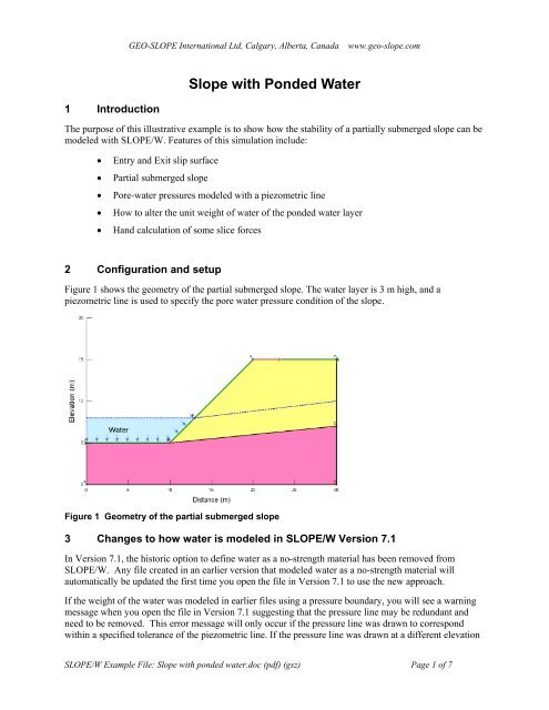
The purpose of this illustrative example is to show how the stability of a partially submerged slope can be<br />
modeled <strong>with</strong> <strong>SLOPE</strong>/W. Features of this simulation include:<br />
• Entry and Exit slip surface<br />
• Partial submerged slope<br />
• Pore-<strong>water</strong> pressures modeled <strong>with</strong> a piezometric line<br />
• How to alter the unit weight of <strong>water</strong> of the <strong>ponded</strong> <strong>water</strong> layer<br />
• Hand calculation of some slice forces<br />
2 Configuration and setup<br />
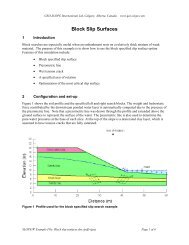
Figure 1 shows the geometry of the partial submerged slope. The <strong>water</strong> layer is 3 m high, and a<br />
piezometric line is used to specify the pore <strong>water</strong> pressure condition of the slope.<br />
Figure 1 Geometry of the partial submerged slope<br />
3 Changes to how <strong>water</strong> is modeled in <strong>SLOPE</strong>/W Version 7.1<br />
In Version 7.1, the historic option to define <strong>water</strong> as a no-strength material has been removed from<br />
<strong>SLOPE</strong>/W. Any file created in an earlier version that modeled <strong>water</strong> as a no-strength material will<br />
automatically be updated the first time you open the file in Version 7.1 to use the new approach.<br />
If the weight of the <strong>water</strong> was modeled in earlier files using a pressure boundary, you will see a warning<br />
message when you open the file in Version 7.1 suggesting that the pressure line may be redundant and<br />
need to be removed. This error message will only occur if the pressure line was drawn to correspond<br />
<strong>with</strong>in a specified tolerance of the piezometric line. If the pressure line was drawn at a different elevation<br />
<strong>SLOPE</strong>/W Example File: <strong>Slope</strong> <strong>with</strong> <strong>ponded</strong> <strong>water</strong>.doc (<strong>pdf</strong>) (gsz) Page 1 of 7
<strong>GEO</strong>-<strong>SLOPE</strong> <strong>International</strong> <strong>Ltd</strong>, Calgary, Alberta, Canada www.geo-slope.com<br />
for some reason, the warning message will not appear. Please note that pressure lines are now referred to<br />
as surcharge loads in Version 7.1, which is more accurate.<br />
The new approach that has been implemented in Version 7.1 computes the stabilizing weight of the <strong>water</strong><br />
acting on the ground surface by looking at the positive pore-<strong>water</strong> pressures that exist along the ground<br />
surface. This approach will work for piezometric lines, pressure heads defined using a spatial function or<br />
finite element computed heads. The presence of positive pore-<strong>water</strong> pressures on the ground surface line<br />
will be visually represented by a shaded area showing the extent of the <strong>ponded</strong> <strong>water</strong> and <strong>with</strong> arrows<br />
indicating the direction that the <strong>water</strong> force will be acting on the free body. Water forces will act normal<br />
to the ground surface line.<br />
Pore-<strong>water</strong> pressures at the base of each slice will be computed differently depending on the method used.<br />
For piezometric lines, the vertical distance from the base of the slice up to the relevant piezometric line<br />
multiplied by the unit weight of <strong>water</strong> as defined under SET: Units and Scale, will determine the pore<strong>water</strong><br />
pressures that exist at the base. For pressure heads developed using a pressure head spatial function,<br />
the pore-<strong>water</strong> pressures will be determined using a numerical process called Kriging. For finite element<br />
generated pore-<strong>water</strong> pressures, the location of the base of the slice, relative to the nearest finite element<br />
nodes, will be determined and the pore-<strong>water</strong> pressures will be interpolated from the finite element<br />
computed results.<br />
For the example being described in this article, a piezometric line has been created and assigned to both<br />
the foundation and embankment materials. Accordingly, the stabilizing weight of the <strong>water</strong> will be<br />
applied in the analysis and is represented <strong>with</strong> a shaded zone and arrows.<br />
3.1 Case 1 – Water layer modeled <strong>with</strong> a piezometric line<br />
In this case, the <strong>ponded</strong> <strong>water</strong> is modeled <strong>with</strong> a piezometric line. Note that the piezometric line is drawn<br />
across the anticipated surface of the <strong>ponded</strong> <strong>water</strong> where pressure equals zero (P = 0). The area between<br />
the ground surface line and the piezometric line has been shaded to indicate the extent of positive pore<strong>water</strong><br />
pressures and arrows have also been painted along the ground surface to indicate the direction that<br />
the <strong>water</strong> force is acting.<br />
The global unit weight of <strong>water</strong> under SET: Units and Scale has been defined as 9.807 kN/m 3 as shown in<br />
Figure 2. This is the value that will be used together <strong>with</strong> the vertical height of the piezometric line to<br />
compute the correct pore-<strong>water</strong> pressure at the base of each slice. This is also the unit weight that will be<br />
used to compute the <strong>water</strong> force acting on the ground surface. If you want to use a different value, you<br />
can change the global value and then do a quick hand-calculation to confirm to yourself that the unit<br />
weight being used is what you have input.<br />
<strong>SLOPE</strong>/W Example File: <strong>Slope</strong> <strong>with</strong> <strong>ponded</strong> <strong>water</strong>.doc (<strong>pdf</strong>) (gsz) Page 2 of 7
<strong>GEO</strong>-<strong>SLOPE</strong> <strong>International</strong> <strong>Ltd</strong>, Calgary, Alberta, Canada www.geo-slope.com<br />
Figure 2: Set Units and Scale dialogue box where you can define the global unit weight of <strong>water</strong><br />
Figure 3 shows the critical slip surface and the factor of safety of the partially submerged slope. The<br />
factor of safety is 1.127.<br />
Figure 3 Critical slip surface and factor of safety of the partial submerged slope when modeled<br />
<strong>with</strong> a piezometric line.<br />
Figure 4 shows the free body diagram and the force polygon of slice #4, which is located half way down<br />
the submerged portion of the slope. Note the line load acting on the top of the slice which represents the<br />
resultant <strong>water</strong> force (F) contributed from the <strong>water</strong> layer.<br />
<strong>SLOPE</strong>/W Example File: <strong>Slope</strong> <strong>with</strong> <strong>ponded</strong> <strong>water</strong>.doc (<strong>pdf</strong>) (gsz) Page 3 of 7
<strong>GEO</strong>-<strong>SLOPE</strong> <strong>International</strong> <strong>Ltd</strong>, Calgary, Alberta, Canada www.geo-slope.com<br />
Figure 4 Free body diagram and force polygon of slice #1<br />
The resultant <strong>water</strong> force (F) contains both the vertical and horizontal <strong>water</strong> force components, which are<br />
computed as being the <strong>water</strong> pressure acting over the vertical or horizontal area of the slice (assuming a<br />
unit depth).<br />
Figure 5 Schematic submerged slice showing the parameters used in the <strong>water</strong> force calculation<br />
Referring to the single schematic slice shown in Figure 5, the resultant force (F) can be spot-checked by<br />
calculating the horizontal and vertical weight components as shown below:<br />
<strong>SLOPE</strong>/W Example File: <strong>Slope</strong> <strong>with</strong> <strong>ponded</strong> <strong>water</strong>.doc (<strong>pdf</strong>) (gsz) Page 4 of 7
<strong>GEO</strong>-<strong>SLOPE</strong> <strong>International</strong> <strong>Ltd</strong>, Calgary, Alberta, Canada www.geo-slope.com<br />
The vertical and horizontal forces acting on a submerged slice can be computed as:<br />
where:<br />
FV = (γ x Hw) x bV x unit depth<br />
FH = (γ x Hw) x bH x unit depth<br />
γ = unit weight of <strong>water</strong><br />
Hw = height of the <strong>water</strong> at the top, centre of the slice<br />
bv = width of the slice as given in the slice force information<br />
bH = bv* tan(α)<br />
For slice #4, <strong>with</strong> a <strong>water</strong> depth of 1.5m, a slice width (bV) of 0.43787 m and a slope angle (α) of 45-<br />
degrees, the vertical and horizontal <strong>water</strong> forces would be:<br />
Fv = (9.807 x 1.5) x 0.43787 m x 1 m = 6.441 kN<br />
FH = (9.807 x 1.5) x [0.43787 m x tan(45)] = 6.441 kN*<br />
* which is the same as the vertical component since the slope is at 45 – degrees.<br />
The resultant force is therefore computed as:<br />
F 2 = √(FH 2 + FV 2 ) = √(6.441 2 + 6.441 2 ) = 9.1 kN<br />
The small difference between the computed F value and the line load acting on the top of the slice is due<br />
to numerical round-off in the hand-calculations.<br />
3.2 Case 2 – Water weight modified <strong>with</strong> a surcharge load<br />
By default, the weight of the <strong>water</strong> and the pore-<strong>water</strong> pressures at the base of the slice will both be<br />
computed using the global weight of <strong>water</strong>. However, there may be a time where you want to use one unit<br />
weight to compute the pore-<strong>water</strong> pressure at the base of the slice and a different unit weight to compute<br />
the <strong>water</strong> force acting on the submerged slices. To do this, you would define the unit weight of <strong>water</strong> for<br />
the pore-<strong>water</strong> pressure computation using SET: Units and Scale, as shown in Figure 2. The global value<br />
would also be used to compute the weight of the slice, but you could modify this value by defining a<br />
surcharge load <strong>with</strong> either a positive or negative unit weight to add or subtract load as desired.<br />
In the second analysis in this detailed example, the global unit weight of <strong>water</strong> has been left at the default<br />
value of 9.807 kN/m 3 , and a surcharge load <strong>with</strong> a positive unit weight of 0.1 kN/m 3 . In defining this<br />
value, the <strong>water</strong> force will essentially be computed as if the unit weight of <strong>water</strong> was defined as 9.907<br />
kN/m 3 .<br />
Figure 6 shows the surcharge load defined overtop of the shaded area representing <strong>ponded</strong> <strong>water</strong> between<br />
the piezometric and the ground surface lines.<br />
<strong>SLOPE</strong>/W Example File: <strong>Slope</strong> <strong>with</strong> <strong>ponded</strong> <strong>water</strong>.doc (<strong>pdf</strong>) (gsz) Page 5 of 7
<strong>GEO</strong>-<strong>SLOPE</strong> <strong>International</strong> <strong>Ltd</strong>, Calgary, Alberta, Canada www.geo-slope.com<br />
Figure 6 A surcharge load used to modify the global weight of <strong>water</strong> for the <strong>water</strong> force acting on<br />
the submerged slope<br />
The critical slip surface and the factor of safety of the partially submerged slope is shown in Figure 7. The<br />
factor of safety is 1.129. The small increase in factor of safety is due to the slight heavier <strong>ponded</strong> <strong>water</strong><br />
which gives additional resisting force against the slide mass.<br />
Figure 7 Critical slip surface and factor of safety <strong>with</strong> the <strong>water</strong> weight modified using a<br />
surcharge load<br />
<strong>SLOPE</strong>/W Example File: <strong>Slope</strong> <strong>with</strong> <strong>ponded</strong> <strong>water</strong>.doc (<strong>pdf</strong>) (gsz) Page 6 of 7
<strong>GEO</strong>-<strong>SLOPE</strong> <strong>International</strong> <strong>Ltd</strong>, Calgary, Alberta, Canada www.geo-slope.com<br />
The free body diagram and the force polygon of slice #4 is shown in Figure 8. Note that the load of<br />
9.0026 kN acting on the top of the slice has increased slightly from the computed value shown in Figure<br />
4, due to the slightly more dense <strong>water</strong> acting on the submerged slope.<br />
Figure 8 Free body diagram and force polygon of slice #4<br />
<strong>SLOPE</strong>/W Example File: <strong>Slope</strong> <strong>with</strong> <strong>ponded</strong> <strong>water</strong>.doc (<strong>pdf</strong>) (gsz) Page 7 of 7