a4 piston displacement - Prins
a4 piston displacement - Prins
a4 piston displacement - Prins

You also want an ePaper? Increase the reach of your titles
YUMPU automatically turns print PDFs into web optimized ePapers that Google loves.
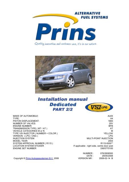
MAKE OF AUTOMOBILE:<br />
AUDI<br />
TYPE:<br />
A4<br />
PISTON DISPLACEMENT: 1800<br />
NUMBER OF VALVES:<br />
20V<br />
ENGINE NUMBER:<br />
BFB<br />
TRANSMISSION TYPE ( MT / AT )<br />
AT<br />
VEHICLE CATEGORIES M or N<br />
M<br />
TYPE VSI INJECTOR ( NUMBER + COLOR )<br />
YELLOW<br />
VERSION ( LPG / CNG )<br />
LPG<br />
INJECTION SYSTEM:<br />
MULTI-POINT INJECTION<br />
MODEL YEAR: 2004<br />
SYSTEM APPROVAL NUMBER ( R115 )<br />
R115-0000**<br />
LOCATION SYSTEM STICKER<br />
If applicable : right side, centre door post<br />
ENGINE SET NUMBER 336/0770100<br />
NUMBER : 076/2606500<br />
DATE : 29/05/2008<br />
Copyright © <strong>Prins</strong> Autogassystemen B.V. 2008 VERSION NR : 2008-02-14 B
TABLE OF CONTENTS<br />
General instructions.......................................................................................................................2<br />
Required equipment / tools / materials for installing a complete system.........................................3<br />
Vehicle check................................................................................................................................3<br />
Base diagram ................................................................................................................................4<br />
VSI approval numbers...................................................................................................................5<br />
Mounting and connection points ....................................................................................................6<br />
Mounting the reducer.....................................................................................................................7<br />
Connection Map-reducer with Turbo sensor...................................................................................8<br />
Mounting the inlet manifold couplings............................................................................................9<br />
Mounting the VSI injector rail.......................................................................................................10<br />
Mounting the filter unit.................................................................................................................11<br />
LPG hoses ..................................................................................................................................11<br />
Mounting the VSI computer .........................................................................................................12<br />
Mounting the fuel selection switch ...............................................................................................12<br />
Electrical connections..................................................................................................................13<br />
Electrical connections..................................................................................................................14<br />
Checklist after installation............................................................................................................15<br />
Trouble code chart ......................................................................................................................16<br />
FOR EXPLANATION AND CIRCUIT DIAGRAMS SEE : INSTALLATION MANUAL GENERAL PART 1 / 2<br />
EXPLANATION OF SYMBOLS :<br />
= IMPORTANT, CAUTION
PAGE 2 076/2606500<br />
Copyright © <strong>Prins</strong> Autogassystemen B.V. 2008<br />
AUDI<br />
A4 1.8 TURBO BFB<br />
General instructions<br />
• The installation of the system shall be done in accordance with the installation manual provided by <strong>Prins</strong><br />
Autogassystemen.<br />
• This manual is based on Dutch regulations, always install the system in accordance to the local regulations.<br />
• Always download the “general manual 1/2 “ from our website for basic instructions and diagrams.<br />
• Always disconnect the battery when installing the LPG system. Make sure the ignition key is outside the<br />
car. Be aware of central door locking, radio / telephone memory code, alarm system.<br />
• Do not place the main fuse into the fuse holder before having completed the installation of the VSI system.<br />
• The VSI computer has to be activated by means of the diagnosis software.<br />
• In the unlikely event the VSI computer fails, it will automatically switch over to petrol.<br />
Never disconnect the VSI computer connector, unless you have removed the main fuse.<br />
• When installing the VSI wiring harness, ensure that it does not run near any of the ignition components.<br />
Solder and insulate all electrical connections.<br />
The wires in the loom are provided with numbers and text. The text on the wire explains the<br />
function of the wire. The wire harness is not model specific, therefore is it may be necessary to<br />
adjust the length of the wires. Ensure maximum care is taken when connecting wiring.<br />
Make professional joints using solder and shrink sleeve. Do not stretch the wiring harness.<br />
• No component of the LPG-system shall be located within 100 mm of the exhaust or similar heat source,<br />
unless such components are adequately shielded against heat.<br />
• Remove any internal burrs, after having shortened the LPG pipe. (This guarantees the maximum flow<br />
through the pipe without pollution.)<br />
• If holes have to be drilled (wear safety glasses) for installing brackets, etc., the drilled holes must always be<br />
treated with an anti-corrosion agent, after the chips have been removed ( especially when mounting a<br />
exterior filler into body work).<br />
• After having completed the installation, check the whole system for gas leakage; use a gas leak detection<br />
device. Also check for leak of engine coolant, petrol and air.<br />
• Fitting and maintenance is only allowed by <strong>Prins</strong> Autogassystemen selected LPG engineers.<br />
• Failure to follow the instructions in this manual can result in a poor or non-working gas installation<br />
or a dangerous situation.<br />
• For maintenance instructions and filter registration see owner manual.<br />
• <strong>Prins</strong> Autogassystemen is not responsible for any damages to people or objects as a result of changes to<br />
<strong>Prins</strong> products.<br />
• Check our website regularly for diagrams, certificates, updates, info-bulletins and product information.<br />
Please fill in the warranty card completely and return it within 8 days after installation.<br />
2
PAGE 3 076/2606500<br />
Copyright © <strong>Prins</strong> Autogassystemen B.V. 2008<br />
AUDI<br />
A4 1.8 TURBO BFB<br />
Required equipment / tools / materials for installing a complete system<br />
- Complete workshop toolbox ( wrenches, screwdrivers, cutters, pliers, ratchet, sockets )<br />
- Car lift<br />
- Portable computer : operating on Windows 98,W2000 or XP.<br />
Internal memory : 16 Mb or more<br />
Memory HD space : 5MB<br />
Screen<br />
: 256 colours, advise colours 16 bits or more<br />
Com port<br />
: 1 free COM port 1 or COM port 2 with a 9 or 25 pins connector<br />
- Vehicle fuel system scan tool or OBD scan tool <strong>Prins</strong> ( part nr. 099/99928 )<br />
- Exhaust gas analyser<br />
- Multimeter<br />
- Oscilloscope<br />
- <strong>Prins</strong> VSI diagnostic software<br />
- <strong>Prins</strong> VSI serial interface<br />
- <strong>Prins</strong> VSI break out box ( part nr. 080/70090 )<br />
- Torque wrench ( 10Nm )<br />
- Portable light<br />
- Assortment drill bits 4 to 12 mm<br />
- Assortment cutters ( ø 20, 30, 50, 70 mm )<br />
- Punching tool ø 70 mm<br />
- Round file<br />
- Portable drill or pneumatic drill<br />
- Threading device ( male M6x1, M8x1, M10x1 )<br />
- Pipe-flaring tool ( for 6 and 8 mm copper pipe )<br />
- Air gun<br />
- Vacuum cleaner<br />
- Hot air gun<br />
- Allan spanner for inlet couplings 3,5mm ( part nr. 099//9970 )<br />
- Reducer adjustment tool ( part nr. 099/9960 )<br />
- Molex extraction tool for VSI switch connector ( part nr. 090/9929 )<br />
- Soldering iron, soldering tin<br />
- Wire-stripping pliers<br />
- Adhesive tape<br />
- Adhesive sealant<br />
- Thread locking compound<br />
- Anti-corrosion agent / black body coating<br />
- Gas leak detection device or foam leak spray<br />
- Shrink sleeves<br />
- Engine coolant<br />
Vehicle check<br />
- Check the vehicle drivability on petrol<br />
- Check the fuel system for error codes ( scan tool )<br />
- Check if the catalytic converter is in good condition ( exhaust gas analyzer )<br />
- Check the condition of the ignition system ( spark plugs, cables, coil )<br />
3
PAGE 4 076/2606500<br />
Copyright © <strong>Prins</strong> Autogassystemen B.V. 2008<br />
AUDI<br />
A4 1.8 TURBO BFB<br />
Base diagram<br />
4
PAGE 5 076/2606500<br />
Copyright © <strong>Prins</strong> Autogassystemen B.V. 2008<br />
AUDI<br />
A4 1.8 TURBO BFB<br />
VSI approval numbers<br />
Reducer VSI LPG <strong>Prins</strong> : E4-67R-010054<br />
Lock-off valve OMB : E8-67R-014327<br />
Lock-off valve Valtek : E4-67R-010041<br />
Injector rail <strong>Prins</strong> : LPG E4-67R-010093<br />
CNG E4-110R-000021<br />
Filter unit T1 / T2 <strong>Prins</strong> : LPG E4-67R-010096<br />
CNG E4-110R-000028<br />
Filter unit Keihin : LPG E4-67R-010177<br />
CNG E4-110R-000091<br />
Injector Keihin :LPG E4-67R-010092<br />
CNG E4-110R-000020<br />
Computer VSI- 4 / 8 / 10 <strong>Prins</strong>: LPG E4-67R-010098<br />
CNG E4-110R-000083<br />
LPG hoses Tubithor : LPG E13-67R-010145<br />
CNG E13-110R-000017<br />
Rubia : LPG E4-67R-010068<br />
CNG E4-110R-000003<br />
5
PAGE 6 076/2606500<br />
Copyright © <strong>Prins</strong> Autogassystemen B.V. 2008<br />
AUDI<br />
A4 1.8 TURBO BFB<br />
Mounting and connection points<br />
A : Reducer H : Engine speed signal RPM ( 40 )<br />
B : Filter unit I : Lambda signal ( 45 + 46 )<br />
C : Injector rail J : “-“ interruption petrol injector<br />
D : VSI Computer K : Overpressure coupling<br />
E : Injection module L : R115 Approval sticker<br />
F : Water connections M : grummet<br />
G : “+” ignition ( 13 ) N : MAP/turbo sensor<br />
R115 approval sticker :<br />
Right side centre door post<br />
6
PAGE 7 076/2606500<br />
Copyright © <strong>Prins</strong> Autogassystemen B.V. 2008<br />
AUDI<br />
A4 1.8 TURBO BFB<br />
Mounting the reducer<br />
Mounting the reducer with the combination bracket on the left side under the coolant reservoir (see<br />
picture).<br />
Overpressure : see page 8<br />
Water connections : series with the 16mm hoses out the cylinder head see picture.<br />
Remove the water hoses on this side<br />
Turn the water hoses towards reducer<br />
7
PAGE 8 076/2606500<br />
Copyright © <strong>Prins</strong> Autogassystemen B.V. 2008<br />
AUDI<br />
A4 1.8 TURBO BFB<br />
Connection Map-reducer with Turbo sensor<br />
8
PAGE 9 076/2606500<br />
Copyright © <strong>Prins</strong> Autogassystemen B.V. 2008<br />
AUDI<br />
A4 1.8 TURBO BFB<br />
Mounting the inlet manifold couplings<br />
Remove the inlet manifold.<br />
Drill 5 holes of 5 mm in the inlet manifold.<br />
Cut M6x1 thread in these holes.<br />
Place the VSI couplings with a lock compound in the inlet manifold.<br />
Watch out that the lock compound doesn’t come inside the VSI couplings.<br />
Mount the hoses on the VSI couplings and place the inlet manifold back on the engine.<br />
Overpressure<br />
9
PAGE 10 076/2606500<br />
Copyright © <strong>Prins</strong> Autogassystemen B.V. 2008<br />
AUDI<br />
A4 1.8 TURBO BFB<br />
Mounting the VSI injector rail<br />
Remove cable duct between cylinder 2 and 3.<br />
Mount the injector rail with a bracket between cylinder 2 and cylinder 3 (see picture).<br />
Remove 2cm of the bracket<br />
10
PAGE 11 076/2606500<br />
Copyright © <strong>Prins</strong> Autogassystemen B.V. 2008<br />
AUDI<br />
A4 1.8 TURBO BFB<br />
Mount the filter directly onto the reducer outlet.<br />
Mounting the filter unit<br />
Filter replacement must be recorded in the service book supplied<br />
LPG hoses<br />
Length of hose, ø 16 mm reducer -> filter unit <strong>Prins</strong> = ± 7 cm<br />
Length of hose, ø 5 mm reducer -> inlet manifold = ±150 cm<br />
Length of hose, ø 11 mm filter unit <strong>Prins</strong> -> rail = ± 13 cm<br />
Length of hose, ø 5 mm VSI injector 1 -> manifold coupling = ± 30 cm<br />
Length of hose, ø 5 mm VSI injector 2 -> manifold coupling = ± 28 cm<br />
Length of hose, ø 5 mm VSI injector 3 -> manifold coupling = ± 28 cm<br />
Length of hose, ø 5 mm VSI injector 4 -> manifold coupling = ± 30 cm<br />
In Case of a Keihin filter : only use two M6x10mm bolts<br />
Cut the hoses on length.<br />
Please observe that there is no damage or fouling to the hoses.<br />
11
PAGE 12 076/2606500<br />
Copyright © <strong>Prins</strong> Autogassystemen B.V. 2008<br />
AUDI<br />
A4 1.8 TURBO BFB<br />
Mounting the VSI computer<br />
Mount the VSI computer on the combination bracket ( see mounting reducer )<br />
Never mount the computer upside down or near a heat source<br />
Mount the switch.<br />
Mounting the fuel selection switch<br />
When mounting the switch, only push on its sides.<br />
Pushing the switch in the centre may result in damage to the switch.<br />
See general manual for programming the selection switch<br />
12
PAGE 13 076/2606500<br />
Copyright © <strong>Prins</strong> Autogassystemen B.V. 2008<br />
AUDI<br />
A4 1.8 TURBO BFB<br />
Electrical connections<br />
Check and measure the wiring in case of changes in the cars wiring colors.<br />
Wire number / code Wire color Connection<br />
50 MAIN GND brown Connect to the '–' of the battery; use a ring terminal for<br />
this purpose.<br />
25-51 +12V BAT red Connect to the '+' of the battery; use a ring terminal for<br />
this purpose or solder.<br />
Do not place the fuse in the holder before having<br />
completed the installation of the LPG system.<br />
33 33G INJ OUT 1 White / yellow Connector VSI-injector to cylinder 1.<br />
34 34 G INJ A PLUS<br />
red<br />
32 32G INJ OUT 2 Green / yellow Connector VSI-injector to cylinder 2.<br />
34 34 G INJ A PLUS<br />
red<br />
31 31G INJ OUT 3 Pink / yellow Connector VSI-injector to cylinder 3.<br />
34 34 G INJ A PLUS<br />
red<br />
30 30G INJ OUT 4 Blue / yellow Connector VSI-injector to cylinder 4.<br />
34 34 G INJ A PLUS<br />
red<br />
13 IGNITION + grey / white Make a connection to + petrol injector.<br />
Wire color : black wire of the injection interruption vsi<br />
connectors<br />
Wire location :vsi wiring loom ( injector petrol<br />
connector)<br />
46 LAMBDA 1-L orange Not used. insulate<br />
40 RPM Purple-white For measuring the engine speed.<br />
Wire color :Green-grey<br />
Wire location :camshaft sensor left-side cylinder head.<br />
13
PAGE 14 076/2606500<br />
Copyright © <strong>Prins</strong> Autogassystemen B.V. 2008<br />
AUDI<br />
A4 1.8 TURBO BFB<br />
Electrical connections<br />
Check and measure the wiring in case of changes in the cars wiring colors.<br />
For measuring the petrol injectors :<br />
Interrupt each petrol injector control wire (injector min)<br />
Each VSI wire has a petrol injector / cylinder number printed on the wire, connect this wire to the<br />
corresponding petrol injector / cylinder.<br />
Connect the bicolored VSI measuring wire to the ecu side, ( wire code: ECU SIDE ).<br />
Connect the corresponding full colored VSI wire to the petrol injector side ( wire code: MIN INJ<br />
SIDE ).<br />
See diagrams: Installation manual general part 1 / 2.<br />
Attention:<br />
Each bicolored measuring wire corresponds to a specific LPG injector and petrol injector /<br />
cylinder number. Do not interchange the wires.<br />
VSI measure wire nr. : Full colored / Bicolored To interrupt petrol injector wire color / location<br />
VSI wire nr. 39<br />
White / White-yellow Interrupt the petrol injectors with the VSI connectors<br />
Petrol injector / cyl. 1<br />
VSI wire nr. 38 Green / Green-yellow Interrupt the petrol injectors with the VSI connectors<br />
Petrol injector / cyl. 2<br />
VSI wire nr. 37<br />
Pink / pink-yellow Interrupt the petrol injectors with the VSI connectors<br />
Petrol injector / cyl. 3<br />
VSI wire nr. 36<br />
Petrol injector / cyl. 4<br />
Blue / blue-yellow Interrupt the petrol injectors with the VSI connectors<br />
14
PAGE 15 076/2606500<br />
Copyright © <strong>Prins</strong> Autogassystemen B.V. 2008<br />
AUDI<br />
A4 1.8 TURBO BFB<br />
Checklist after installation<br />
1. Connect the serial interface wire and run the VSI diagnosis program.<br />
Install the VSI fuse, and program the switch.<br />
Turn the ignition key in the accessory position.<br />
When working on the car, beware of moving and rotating parts in the engine compartment.<br />
2. When commissioning the LPG system, you must activate the VSI computer with the diagnosis<br />
software. When the VSI computer has not been activated, it will keep generating error code<br />
160. To activate the VSI computer, select function F11 (activate ECM).<br />
3. Check whether the program in the VSI computer matches with the car ( dedicated engine set ):<br />
Refer with F2 to the box number and car description in the diagnosis software and compare<br />
these with the set number.<br />
4. The system will switch over to LPG as soon as the temperature of the coolant (T-ect)<br />
becomes higher than the parameter T-min set and when the TSO-cold time is expired.<br />
5. Check all components and connections for any gas leakage ( use a LPG leak detector device<br />
or a fluid detection like soap. Caution for moving and rotating parts in the engine<br />
compartment !<br />
6. Let the engine run warm on petrol >80°C.<br />
Check if the evaporator heats up.<br />
Check the engine signals, petrol injection time, RPM, ECT, lambda<br />
Let the engine run idle on LPG.<br />
Adjust the evaporator pressure. Refer to the parameter list ( or F2 : ID box) for the idle level<br />
value set.<br />
Adjust the evaporator pressure in such a way that the pressure measured ( P-sys ) equals the<br />
idle level value.<br />
Turn the socket-head screw at the front of the evaporator to adjust the pressure.<br />
An error code will be generated whenever the pressure variation is to high.<br />
Seal the evaporator with the sticker included in the delivery after having adjusted the pressure.<br />
7. Use the diagnosis software to check again all input and output signals.<br />
8. Check the system for error codes and solve these, if required.<br />
Check the petrol MMS for EOBD error codes.<br />
Place the protection connector on the VSI communication connector.<br />
9. Make a test drive and check the drivability on LPG and petrol.<br />
15
PAGE 16 076/2606500<br />
Copyright © <strong>Prins</strong> Autogassystemen B.V. 2008<br />
AUDI<br />
A4 1.8 TURBO BFB<br />
Trouble code chart<br />
Trouble code Definition Check / solution<br />
100 Lambda to long to rich. Check when operating on petrol and LPG that there is good lambda signal<br />
movement.<br />
101 Lambda to long to lean. Check when operating on petrol and LPG that there is good lambda signal<br />
movement.<br />
Check when operating on petrol and LPG that there is good lambda signal<br />
movement.<br />
102 Lambda to long to lean during open<br />
loop.<br />
110 T-ECT>= 171°C Check if the ECT sensor (blue) in the reducer is connector is connected to<br />
ground.<br />
111 T-ECT>= -40°C Check if the ECT sensor (blue) in the reducer has a power connection.<br />
120 T-LPG>= 171°C Check the ground connection of the Pressure/temperature sensor in the<br />
filter unit.<br />
121 T-LPG>= -40°C Check the power connection of the Pressure/temperature sensor in the filter<br />
unit.<br />
150 Psys= 90°C LPG computer circuit board to hot, replace the VSI computer in a cooler<br />
area.<br />
181 Battery voltage to high Check board voltage / alternator output and condition of the battery.<br />
210-220-230-240-250-260-270- VSI injector Injector current to high, check for short circuiting<br />
280<br />
overload<br />
211-221-231-241-251-261-271- VSI injector Injector current to low, check for bad connections.<br />
281<br />
noload<br />
310 Adjusted pressure on idle out of Adjust the idle pressure to the value shown by parameter “ Idle Level “<br />
range<br />
311 Programm error during flahing the Check parameter settings, contact <strong>Prins</strong> Autogassystemen.<br />
memory<br />
320 Psys voltage to low Check the ground connection of the Pressure/temperature sensor in the<br />
filter unit.<br />
321 Psys voltage to high Check the power connection of the Pressure/temperature sensor in the filter<br />
unit.<br />
322 Psys > 3,5 Bar Check the coolant temperature (T-ect) and the evaporator for leakage of the<br />
first stage.<br />
330 unexpected parameter change Contact <strong>Prins</strong> Autogassystemen.<br />
340 reducer warms up to slow Check the water connections / circuit.<br />
341 Gas leakage, system pressure is less then Check the system for gasleakage.<br />
1.25 bar after 4 hours when the engine<br />
is not running<br />
- System switches to LPG but engine<br />
stalls immediately.<br />
LPG tank empty ?<br />
Lock-off valves open ?<br />
- No injection timing on LPG ( 0 Check the injection module.<br />
Msec.)<br />
- The LPG system switches<br />
constantly between LPG and Petrol<br />
- Check coolant system for air.<br />
- T-ect sensor in the evaporator malfunction.<br />
- Engine hesitates on high revs, and<br />
not running on all cylinders. Engine<br />
runs good on idle.<br />
Check for kinked or jammed LPG hoses (between VSI injector and<br />
couplings).<br />
Check for blocked inlet couplings.<br />
- Switch LED’s don’t lit up Check the main fuse of the VSI system<br />
Check ignition+ (VSI wire 13)<br />
- Fault codes when turning the ignition<br />
off ( key out the ignition )<br />
Caused by different switch off times between ignition+ and injector power.<br />
Connect VSI wire 13 to the petrol injector feed instead of ignition+.<br />
- The orange LED on the switch<br />
flashes<br />
Activate the LPG computer with the diagnostic program, using the F11<br />
function key.<br />
- The LPG system switches to LPG LPG tank empty?<br />
but engine stalls immediately<br />
- Not running on all cylinders on lpg Check parameter 10, number of cylinders.<br />
- No injection times on lpg Check the connections of the injection module.<br />
- Injection time “falls” to 0 mSec on Check the injection module.<br />
LPG<br />
- Check engine while running on LPG, Replace injection module<br />
injector circuit malfunction, no<br />
lambda control (limb home)<br />
- Not starting / running on petrol Check the connections of the injection module.<br />
16