grand cherokee piston displacement - Prins
grand cherokee piston displacement - Prins
grand cherokee piston displacement - Prins
- No tags were found...

Create successful ePaper yourself
Turn your PDF publications into a flip-book with our unique Google optimized e-Paper software.
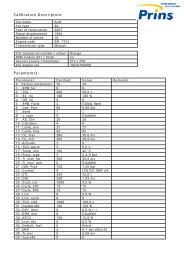
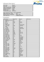
MAKE OF AUTOMOBILE:JEEPTYPE:GRAND CHEROKEEPISTON DISPLACEMENT: 4700NUMBER OF VALVES: 16ENGINE NUMBER: 4.7V8TRANSMISSION TYPE ( MT / AT )ATVEHICLE CATEGORIES M or NmTYPE VSI INJECTOR (COLOR )OrangeVERSION ( LPG / CNG )LPGINJECTION SYSTEM:MULTI-POINT INJECTIEMODEL YEAR: 1999-2005SYSTEM APPROVAL NUMBER ( R115 ) R115-000077LOCATION SYSTEM STICKERright side, centre door postENGINE SET NUMBER 337/1290800 - 337/1290900NUMBER : 076/3206900DATE : 2007-11-26Copyright © <strong>Prins</strong> Autogassystemen B.V. 2008 VERSION NR : 2008-02-14 B
TABLE OF CONTENTSRequired equipment / tools / materials for installing a complete system.........................................2Vehicle check................................................................................................................................2Base diagram ................................................................................................................................3VSI approval numbers...................................................................................................................4Mounting and connection points ....................................................................................................5Mounting the reducer.....................................................................................................................6Mounting the inlet manifold couplings............................................................................................7Mounting the VSI injector rail.........................................................................................................8Mounting the filter unit...................................................................................................................9LPG hoses ....................................................................................................................................9Mounting the VSI computer .........................................................................................................10Mounting the fuel selection switch ...............................................................................................10Electrical connections..................................................................................................................11Electrical connections..................................................................................................................13Checklist after installation............................................................................................................14Trouble code chart ......................................................................................................................15FOR EXPLANATION AND CIRCUIT DIAGRAMS SEE : INSTALLATION MANUAL GENERAL PART 1 / 2EXPLANATION OF SYMBOLS := IMPORTANT, CAUTION
PAGE 2 076/3206900Copyright © <strong>Prins</strong> Autogassystemen B.V. 2008JEEPGRAND CHEROKEE 4.7V8 1999-2005VERSION NR : BRequired equipment / tools / materials for installing a complete system- Complete workshop toolbox ( wrenches, screwdrivers, cutters, pliers, ratchet, sockets )- Car lift- Portable computer : operating on Windows 98,W2000 or XP.Internal memory : 16 Mb or moreMemory HD space : 5MBScreen: 256 colours, advise colours 16 bits or moreCom port: 1 free COM port 1 or COM port 2 with a 9 or 25 pins connector- Vehicle fuel system scan tool or OBD scan tool <strong>Prins</strong> ( part nr. 099/99928 )- Exhaust gas analyser- Multimeter- Oscilloscope- <strong>Prins</strong> VSI diagnostic software- <strong>Prins</strong> VSI serial interface- <strong>Prins</strong> VSI break out box ( part nr. 080/70090 )- Torque wrench ( 10Nm )- Portable light- Assortment drill bits 4 to 12 mm- Assortment cutters ( ø 20, 30, 50, 70 mm )- Punching tool ø 70 mm- Round file- Portable drill or pneumatic drill- Threading device ( male M6x1, M8x1, M10x1 )- Pipe-flaring tool ( for 6 and 8 mm copper pipe )- Air gun- Vacuum cleaner- Hot air gun- Allan spanner for inlet couplings 3,5mm ( part nr. 099//9970 )- Reducer adjustment tool ( part nr. 099/9960 )- Molex extraction tool for VSI switch connector ( part nr. 090/9929 )- Soldering iron, soldering tin- Wire-stripping pliers- Adhesive tape- Adhesive sealant- Thread locking compound- Anti-corrosion agent / black body coating- Gas leak detection device or foam leak spray- Shrink sleeves- Engine coolantVehicle check- Check the vehicle drivability on petrol- Check the fuel system for error codes ( scan tool )- Check if the catalytic converter is in good condition ( exhaust gas analyzer )- Check the condition of the ignition system ( spark plugs, cables, coil )2
PAGE 3 076/3206900Copyright © <strong>Prins</strong> Autogassystemen B.V. 2008JEEPGRAND CHEROKEE 4.7V8 1999-2005VERSION NR : BBase diagramVSI base diagram 8 cylinder LPG (080/72060)Part :Part nr. :Injector simulator091/71004Part :Part nr. :LPG approval :CNG approval :Filter unit080/80210E4-67R-010096E4-110R-000028petrol injectorsPart :Part nr. :T-lpg + Psys sensor080/70032- - + - + - +Part : 11 mm LPG hosePart nr. : 081/24003LPG approval : E4-67R-010068E13-67R-010145CNG approval : E4-110R-000003E13-110R-000017Part :Part nr. :LPG approval :CNG approval :16 mm LPG hose081/25001E4-67R-010068E13-67R-010145E4-110R-000003E13-110R-000017overpressure hosePart : Injector simulatorPart nr. : 091/71004petrol injectors- - + - + - +Part :reducer lock-off valvePart nr. : 081/13014 (8mm)LPG approval : E4-67R-010041 ValtecLPG approval : E8-67R-014327 OMBPart :Part nr. :T-ect sensor077/70001Part :reducerPart nr. : 180/10003 ( 8mm )Part nr. : 180/10013 ( 8mm MAP )LPG approval : E4-67R-010054petrol ECU- +Designed : T.S. 22-01-2007Version / Date : 4 / 20-12-2007engine RPM ignition+ batteryPart :Part nr. :LPG approval :CNG approval :5 mm LPG hose081/23001E4-67R-010068E13-67R-010145E4-110R-000003E13-110R-000017Part : Tank gaugePart nr. : 080/70065 HallPart nr. : 080/70064 0 -90 OhmPart nr. : 085/20020 0 -95 OhmPRINSBLA CK BLUEGROUND SIGNALtank lock-off valvePart :Part nr. :LPG approval :CNG approval :Injector rail180/304**E4-67R-010093E4-110R-000021petrol injectorinlet manifold exhaust manifoldLambda sensor1 2Part : Fuel switchPart nr. : 080/70058 Hal l / OhmPart nr. : 080/70059 93-9,3 OhmPart nr. : 080/70063 0-5 VoltdiagnoseconnectorPart :Part nr. :connector cover080/70130Lambda sensorPart : wiring loomPart nr. : 080/72060Part :Part nr. :LPG approval :CNG approval :VSI computer080/70003E4-67R-010098E4-110R-000083++013
PAGE 4 076/3206900Copyright © <strong>Prins</strong> Autogassystemen B.V. 2008JEEPGRAND CHEROKEE 4.7V8 1999-2005VERSION NR : BVSI approval numbersReducer VSI LPG <strong>Prins</strong> : E4-67R-010054Lock-off valve OMB : E8-67R-014327Lock-off valve Valtek : E4-67R-010041Injector rail <strong>Prins</strong> : LPG E4-67R-010093CNG E4-110R-000021Filter unit T1 / T2 <strong>Prins</strong> : LPG E4-67R-010096CNG E4-110R-000028Filter unit Keihin : LPG E4-67R-010177CNG E4-110R-000091Injector Keihin :LPG E4-67R-010092CNG E4-110R-000020Computer VSI- 4 / 8 / 10 <strong>Prins</strong>: LPG E4-67R-010098CNG E4-110R-000083LPG hoses Tubithor : LPG E13-67R-010145CNG E13-110R-000017Rubia : LPG E4-67R-010068CNG E4-110R-0000034
PAGE 5 076/3206900Copyright © <strong>Prins</strong> Autogassystemen B.V. 2008JEEPGRAND CHEROKEE 4.7V8 1999-2005VERSION NR : BMounting and connection pointsGH iKEF8642CC7531ABJDA : Reducer H : Engine speed signal RPM ( 40 )B : Filter unit I : Lambda signal ( 45 + 46 )C : Injector rail J : “-“ interruption petrol injectorD : VSI Computer K : Overpressure couplingE : Injection module L : Approval stickerF : Water connections M : grummetG : “+” ignition ( 13 )R115 approval sticker :Right side centre door post5
PAGE 6 076/3206900Copyright © <strong>Prins</strong> Autogassystemen B.V. 2008JEEPGRAND CHEROKEE 4.7V8 1999-2005VERSION NR : BMounting the reducerMount the reducer with the device frame. Mount the frame on the original threaded end of the brakebooster.Overpressure hose coupling: With T-piece into a vacuum hose connected to the intake manifold.Water connections: Parallel with the hose from the coolant reservoir to the heater connection on thescuttle board.Filter replacement must be recorded in the service book supplied6
PAGE 7 076/3206900Copyright © <strong>Prins</strong> Autogassystemen B.V. 2008JEEPGRAND CHEROKEE 4.7V8 1999-2005VERSION NR : BMounting the inlet manifold couplingsRemove the ignition coils.Drill 8 holes of 4,8 mm in the inlet manifold. Make sure that the plastic doesn’t come inside the inletmanifold.Tap M6 in these holes.Place the couplings with a lock compound in the inlet manifold.Watch out that the lock compound doesn’t come inside the couplings.Mount the hoses on the couplings and place the inlet manifold back on the engine.Cylinder 1 / 3 / 5 / 7 :Cylinder 2 / 4 / 6 / 8 :7
PAGE 8 076/3206900Copyright © <strong>Prins</strong> Autogassystemen B.V. 2008JEEPGRAND CHEROKEE 4.7V8 1999-2005VERSION NR : BMounting the VSI injector railMount the injector rail(s) on the original threaded end(s) on the right and left side of the manifold.Cylinder 1 / 3 / 5 / 7 :Cylinder 2 / 4 / 6 / 8 :8
PAGE 9 076/3206900Copyright © <strong>Prins</strong> Autogassystemen B.V. 2008JEEPGRAND CHEROKEE 4.7V8 1999-2005VERSION NR : BMounting the filter unitMount the filter unit by means of a bracket on the LPG valve.Filter replacement must be recorded in the service book suppliedLPG hosesLength of hose, ø 16 mm reducer -> filter unit = ± 50 cmLength of hose, ø 5 mm reducer -> inlet manifold = ± 45 cmLength of hose, ø 11 mm filter unit -> rail = ± 50 cmLength of hose, ø 11 mm filter unit -> rail = ± 120 cmLength of hose, ø 5 mm VSI injector 1 -> manifold coupling = ± 30 cmLength of hose, ø 5 mm VSI injector 2 -> manifold coupling = ± 30 cmLength of hose, ø 5 mm VSI injector 3 -> manifold coupling = ± 30 cmLength of hose, ø 5 mm VSI injector 4 -> manifold coupling = ± 30 cmLength of hose, ø 5 mm VSI injector 5 -> manifold coupling = ± 30 cmLength of hose, ø 5 mm VSI injector 6 -> manifold coupling = ± 30 cmLength of hose, ø 5 mm VSI injector 7 -> manifold coupling = ± 30 cmLength of hose, ø 5 mm VSI injector 8 -> manifold coupling = ± 30 cmCut the hoses on length.Please observe that there is no damage or fouling to the hoses.9
PAGE 10 076/3206900Copyright © <strong>Prins</strong> Autogassystemen B.V. 2008JEEPGRAND CHEROKEE 4.7V8 1999-2005VERSION NR : BMounting the VSI computerRemove the air cleaner box.Mount the vsi computer under the left head light unit.Never mount the computer upside down or near a heat sourceMount the switch.Mounting the fuel selection switchWhen mounting the switch, only push on its sides.Pushing the switch in the centre may result in damage to the switch.See general manual for programming the selection switch10
PAGE 11 076/3206900Copyright © <strong>Prins</strong> Autogassystemen B.V. 2008JEEPGRAND CHEROKEE 4.7V8 1999-2005VERSION NR : BElectrical connectionsCheck and measure the wiring in case of changes in the cars wiring colors.Wire number / code Wire color Connection50 MAIN GND brown Connect to the '–' of the battery; use a ring terminal forthis purpose.Or petrol computer, black connector, C1, position 3225-51 +12V BAT red Connect to the '+' of the battery; use a ring terminal forthis purpose or solder.Or petrol computer, black connector, C1, position 22Do not place the fuse in the holder before havingcompleted the installation of the LPG system.33 33G INJ OUT 1 White / yellow Connector VSI-injector to cylinder 1.34 34 G INJ A PLUSred32 32G INJ OUT 2 Green / yellow Connector VSI-injector to cylinder 2.34 34 G INJ A PLUSred31 31G INJ OUT 3 Pink / yellow Connector VSI-injector to cylinder 3.34 34 G INJ A PLUSred30 30G INJ OUT 4 Blue / yellow Connector VSI-injector to cylinder 4.34 34 G INJ A PLUSred5 5G INJ OUT 5 Grey / yellow Connector VSI-injector to cylinder 5.6 34 G INJ A PLUSred4 4G INJ OUT 6 Brown / yellow Connector VSI-injector to cylinder 6.6 34 G INJ A PLUSred3 3G INJ OUT 7 Lightblue / yellow Connector VSI-injector to cylinder 7.6 34 G INJ A PLUSred2 2G INJ OUT8 Red / yellow Connector VSI-injector to cylinder 8.6 34 G INJ A PLUSred13 IGNITION + grey / white Make a connection to + petrol injector.Wire color : GREEN-lightGREENWire location : in relay /fuse box, under fuse 26, thereare two GREEN-lightGREEN wires on contact 37, useone of them. Or near a petrol injector connector.46 LAMBDA 1-L orange For the measurement of the lambda signal of cylinderbank 1.Connect the wire in parallel to the lambda sensor.Wire color : green-redWire location : C1, pos. 24.45 LAMBDA 2-R orange / white For the measurement of the lambda signal of cylinderbank 2. Connect the wire in parallel to the lambdasensor.Wire color : brown-whiteWire location : C1, pos. 26.11
PAGE 12 076/3206900Copyright © <strong>Prins</strong> Autogassystemen B.V. 2008JEEPGRAND CHEROKEE 4.7V8 1999-2005VERSION NR : B40 RPM Purple-white For measuring the engine speed.Cable color : purple rpm module => BROWN-PINKPurple-white module => purple-white VSI wire 40Brown module => brown VSI wire 50Grey-white => grey-white VSI wire 13Purple => connect to BROWN-PINK wire,Cable location : petrol computer, white connector, C2.Pos. 9RPMmodulerpm 40purple-whitepurpleground 50ignition + 13grey-whitesolderbrown--+VSIcomputerignition +or petrol injector +batteryignitioncoil -12
PAGE 13 076/3206900Copyright © <strong>Prins</strong> Autogassystemen B.V. 2008JEEPGRAND CHEROKEE 4.7V8 1999-2005VERSION NR : BElectrical connectionsCheck and measure the wiring in case of changes in the cars wiring colors.For measuring the petrol injectors :Interrupt each petrol injector control wire (injector min)Each VSI wire has a petrol injector / cylinder number printed on the wire, connect this wire to thecorresponding petrol injector / cylinder.Connect the bicolored VSI measuring wire to the ecu side, ( wire code: ECU SIDE ).Connect the corresponding full colored VSI wire to the petrol injector side ( wire code: MIN INJSIDE ).See diagrams: Installation manual general part 1 / 2.Attention:Each bicolored measuring wire corresponds to a specific LPG injector and petrol injector /cylinder number. Do not interchange the wires.VSI measure wire nr. : Full colored / Bicolored To interrupt petrol injector wire color / locationVSI wire nr. 39Petrol injector / cyl. 1White / White-yellow Color : WHITE-BLUELocation : ecu, white connector, C2 pin 4VSI wire nr. 38Petrol injector / cyl. 2Green / Green-yellow Color : BROWNLocation : ecu, white connector, C2 pin 15VSI wire nr. 37Petrol injector / cyl. 3Pink / pink-yellow Color : YELLOW-WHITELocation : ecu, white connector, C2 pin 5VSI wire nr. 36Petrol injector / cyl. 4Blue / blue-yellow Color : lightBLUE-BROWNLocation : ecu, white connector, C2 pin 16VSI wire nr. 11Petrol injector / cyl. 5Grey / grey-yellow Color : GREYLocation : ecu, white connector, C2 pin 6VSI wire nr. 10Petrol injector / cyl. 6Brown / brown-yellow Color : BROWN-BLUELocation : ecu, white connector, C2 pin 12VSI wire nr. 9Petrol injector / cyl. 7LightBlue / lightBlue-yellow Color : darkBLUE-BROWNLocation : ecu, white connector, C2 pin 2VSI wire nr. 8Petrol injector / cyl. 8Red / red-yellow Color : darkBLUE-GREYLocation : ecu, white connector, C2 pin 1313
PAGE 14 076/3206900Copyright © <strong>Prins</strong> Autogassystemen B.V. 2008JEEPGRAND CHEROKEE 4.7V8 1999-2005VERSION NR : BChecklist after installation1. Connect the serial interface wire and run the VSI diagnosis program.Install the VSI fuse, and program the switch.Turn the ignition key in the accessory position.When working on the car, beware of moving and rotating parts in the engine compartment.2. When commissioning the LPG system, you must activate the VSI computer with the diagnosissoftware. When the VSI computer has not been activated, it will keep generating error code160. To activate the VSI computer, select function F11 (activate ECM).3. Check whether the program in the VSI computer matches with the car ( dedicated engine set ):Refer with F2 to the box number and car description in the diagnosis software and comparethese with the set number.4. The system will switch over to LPG as soon as the temperature of the coolant (T-ect)becomes higher than the parameter T-min set and when the TSO-cold time is expired.5. Check all components and connections for any gas leakage ( use a LPG leak detector deviceor a fluid detection like soap. Caution for moving and rotating parts in the enginecompartment !6. Let the engine run warm on petrol >80°C.Check if the evaporator heats up.Check the engine signals, petrol injection time, RPM, ECT, lambdaLet the engine run idle on LPG.Adjust the evaporator pressure. Refer to the parameter list ( or F2 : ID box) for the idle levelvalue set.Adjust the evaporator pressure in such a way that the pressure measured ( P-sys ) equals theidle level value.Turn the socket-head screw at the front of the evaporator to adjust the pressure.An error code will be generated whenever the pressure variation is to high.Seal the evaporator with the sticker included in the delivery after having adjusted the pressure.7. Use the diagnosis software to check again all input and output signals.8. Check the system for error codes and solve these, if required.Check the petrol MMS for EOBD error codes.Place the protection connector on the VSI communication connector.9. Make a test drive and check the drivability on LPG and petrol.14
PAGE 15 076/3206900Copyright © <strong>Prins</strong> Autogassystemen B.V. 2008JEEPGRAND CHEROKEE 4.7V8 1999-2005VERSION NR : BTrouble code chartTrouble code Definition Check / solution100 Lambda to long to rich. Check when operating on petrol and LPG that there is good lambda signalmovement.101 Lambda to long to lean. Check when operating on petrol and LPG that there is good lambda signalmovement.Check when operating on petrol and LPG that there is good lambda signalmovement.102 Lambda to long to lean during openloop.110 T-ECT>= 171°C Check if the ECT sensor (blue) in the reducer is connector is connected toground.111 T-ECT>= -40°C Check if the ECT sensor (blue) in the reducer has a power connection.120 T-LPG>= 171°C Check the ground connection of the Pressure/temperature sensor in thefilter unit.121 T-LPG>= -40°C Check the power connection of the Pressure/temperature sensor in the filterunit.150 Psys= 90°C LPG computer circuit board to hot, replace the VSI computer in a coolerarea.181 Battery voltage to high Check board voltage / alternator output and condition of the battery.210-220-230-240-250-260-270- VSI injector Injector current to high, check for short circuiting280overload211-221-231-241-251-261-271- VSI injector Injector current to low, check for bad connections.281noload310 Adjusted pressure on idle out of Adjust the idle pressure to the value shown by parameter “ Idle Level “range311 Programm error during flahing the Check parameter settings, contact <strong>Prins</strong> Autogassystemen.memory320 Psys voltage to low Check the ground connection of the Pressure/temperature sensor in thefilter unit.321 Psys voltage to high Check the power connection of the Pressure/temperature sensor in the filterunit.322 Psys > 3,5 Bar Check the coolant temperature (T-ect) and the evaporator for leakage of thefirst stage.330 unexpected parameter change Contact <strong>Prins</strong> Autogassystemen.340 reducer warms up to slow Check the water connections / circuit.341 Gas leakage, system pressure is less then Check the system for gasleakage.1.25 bar after 4 hours when the engineis not running- System switches to LPG but enginestalls immediately.LPG tank empty ?Lock-off valves open ?- No injection timing on LPG ( 0 Check the injection module.Msec.)- The LPG system switchesconstantly between LPG and Petrol- Check coolant system for air.- T-ect sensor in the evaporator malfunction.- Engine hesitates on high revs, andnot running on all cylinders. Engineruns good on idle.Check for kinked or jammed LPG hoses (between VSI injector andcouplings).Check for blocked inlet couplings.- Switch LED’s don’t lit up Check the main fuse of the VSI systemCheck ignition+ (VSI wire 13)- Fault codes when turning the ignitionoff ( key out the ignition )Caused by different switch off times between ignition+ and injector power.Connect VSI wire 13 to the petrol injector feed instead of ignition+.- The orange LED on the switchflashesActivate the LPG computer with the diagnostic program, using the F11function key.- The LPG system switches to LPG LPG tank empty?but engine stalls immediately- Not running on all cylinders on lpg Check parameter 10, number of cylinders.- No injection times on lpg Check the connections of the injection module.- Injection time “falls” to 0 mSec on Check the injection module.LPG- Check engine while running on LPG, Replace injection moduleinjector circuit malfunction, nolambda control (limb home)- Not starting / running on petrol Check the connections of the injection module.15