Download Reverse Engineering & Rapid Prototyping Brochure
Download Reverse Engineering & Rapid Prototyping Brochure
Download Reverse Engineering & Rapid Prototyping Brochure

Create successful ePaper yourself
Turn your PDF publications into a flip-book with our unique Google optimized e-Paper software.
<strong>Reverse</strong> <strong>Engineering</strong> &<br />
<strong>Rapid</strong> <strong>Prototyping</strong><br />
www.udri.udayton.edu<br />
UDRI operates a comprehensive facility aimed at reducing product development cycle<br />
cost and time. Capabilities include reverse engineering of existing products via 3-D<br />
digitization and geometric analysis, 3-D printing of prototype models, and computer<br />
design and optimization of molds and tools to manufacture newly developed products.<br />
Applications include consumer, industrial, or military products manufactured from<br />
plastics, polymer composites, or metals, as well as tooling for all types of plastic<br />
molding processes, composite curing techniques, and sheet metal stamping.<br />
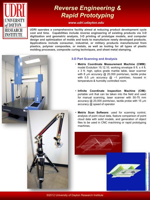
3-D Part Scanning and Analysis<br />
• Metris Coordinate Measurement Machine (CMM):<br />
model Evolution 15.12.10, working envelope 8 ft. x 4 ft.<br />
x 3 ft. high, optics grade marble table, laser scanner<br />
with 8 mm accuracy @ 20,000 points/sec, tactile probe<br />
with 0.5 mm accuracy @ ~1 point/sec, housed in<br />
temperature & humidity controlled room.<br />
• Infinite Coordinate Inspection Machine (CIM):<br />
portable unit that can be taken into the field and used<br />
for manual scanning, laser scanner with 50-75 mm<br />
accuracy @ 20,000 points/sec, tactile probe with 15 mm<br />
accuracy @ speed of operator<br />
• Metris Scan Software: used for scanning control,<br />
analysis of point cloud data, feature comparison of point<br />
cloud data with solid models, and generation of object<br />
files to be used in CNC machining or rapid prototyping<br />
machines.<br />
©2012 University of Dayton Research Institute
Shaping the Technology of Tomorrow<br />
www.udri.udayton.edu<br />
3-D Printing / <strong>Rapid</strong> <strong>Prototyping</strong><br />
• Fused deposition modeling (FDM) process, model<br />
Dimension SST 1200es (Stratasys Inc.)<br />
• Working envelope 10 in. x 10 in. x 12 in. high<br />
• Layer thickness 0.007 in. or 0.010 in.<br />
• ABS plastic materials of 9 color variations (black, white,<br />
red, blue, olive, yellow, nectarine, gray, natural)<br />
• Soluble support materials used and removed in post<br />
production bath<br />
3D Printer<br />
Solvent Bath<br />
Dimension SST 1200es<br />
3D Printed Motor<br />
Housing<br />
3D Printed Ice-<br />
Scraper Assembly<br />
3D Printed MAV Assembly<br />
Mold Design and Analysis<br />
• Solid Works 2010 : software used to design molds beginning with<br />
reverse engineering master pattern file or via manual development;<br />
user can add sprues, gates, vents, knock-out pins, support<br />
structures, draft angles, cooling lines etc.; mold design is output to<br />
IGES format for Moldflow analysis or CNC machining.<br />
• Moldflow 2010: software used to simulate injection molding<br />
process, used iteratively with Solid Words to optimize mold design<br />
prior to final production<br />
Injection Mold Simulation<br />
For further information please contact:<br />
Jared Stonecash<br />
937-229-4361<br />
Jared.Stonecash@udri.udayton.edu<br />
©2012 University of Dayton Research Institute