Sprocket Catalog - U.S. Tsubaki, Inc.
Sprocket Catalog - U.S. Tsubaki, Inc.
Sprocket Catalog - U.S. Tsubaki, Inc.

You also want an ePaper? Increase the reach of your titles
YUMPU automatically turns print PDFs into web optimized ePapers that Google loves.
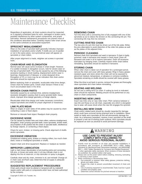
U.S. TSUBAKI SPROCKETS<br />
Maintenance Checklist<br />
Regardless of application, all chain systems should be inspected<br />
on a regularly scheduled basis for worn, damaged or broken parts,<br />
possible interference by other system components, and proper<br />
lubrication. Normal maintenance procedures can prevent most of<br />
the conditions described below. Carefully inspect roller chain drives<br />
on the same schedule as associated equipment.<br />
SPROCKET MISALIGNMENT<br />
Wear on the sides of sprocket teeth generally indicates improper<br />
installation of sprockets and/or shafts. If shafts are out of parallel<br />
or not in the same plane, non-symmetrical wear will appear on<br />
sprockets or chain rollers.<br />
After proper alignment is made, retighten set screws in sprocket<br />
hubs.<br />
CHAIN WEAR AND ELONGATION<br />
Normal wear will cause some increase in chain length. However,<br />
if a sudden increase in elongation occurs, look for severe wear on<br />
the tips of sprocket teeth. This may be caused by any of the following:<br />
excessive loading or shock loading, displacement and/or wear in<br />
bearings, displacement of takeups, or under-designed drive.<br />
Elongation of 3% or more may be an indication that chain and/or<br />
sprockets should be replaced.<br />
Before replacing chain or sprockets, recalculate initial drive design.<br />
Check chain for broken parts. Check chain tension if there is too<br />
much accumulated slack in the drive.<br />
BROKEN CHAIN PARTS<br />
Generally caused by an overload drive, extreme misalignment,<br />
excessive elongation causing chain to jump sprocket teeth, heavy<br />
shock, improper drive design geometry, or foreign objects.<br />
Recalculate initial drive design and make necessary corrections.<br />
Inspect sprockets and shafts for proper alignment or looseness.<br />
LINK PLATE WEAR<br />
Wear on edges of outer sides of link plates may be caused by chain<br />
contacting a case or fixed object.<br />
Remove or relocate fixed object. Readjust chain properly.<br />
EXCESSIVE NOISE<br />
Can be caused by broken links and chain rollers, extreme misalignment,<br />
elongation, chain jumping sprocket teeth, loose sprockets, broken teeth,<br />
accumulation of dirt packed into the chain or sprocket teeth, interference<br />
by foreign objects, or contacting a fixed object.<br />
Check for worn, broken, or missing parts. Check alignment of shafts<br />
and/or sprockets.<br />
EXCESSIVE VIBRATION<br />
Unbalanced rotating parts, broken or missing rollers, too much chain<br />
slack, loose or misaligned sprockets or shafts.<br />
Inspect chain and drive equipment. Replace or readjust as needed.<br />
IMPROPER LUBRICATION<br />
Light or dark brown discoloration of pin-bushing joints and connecting<br />
link pins, or brown-red oxide color in oil may indicate chain is not<br />
dipping into the oil reservoir, or drip lubricator or spray is plugged.<br />
Carefully clean and dry chain, immerse in oil, and reinstall. Change oil<br />
in chain case and flush case. Determine that oil supply is adequate<br />
and unimpeded.<br />
SUGGESTED REPLACEMENT PROCEDURES<br />
Chain parts should never be altered or tampered with by makeshift<br />
repairs and/or with parts or components which have not been authorized<br />
by the company.<br />
REMOVING CHAIN<br />
Turn the drive until a connecting link is fully engaged with one of the<br />
sprockets so as to relieve the tension on the connecting link pin. The<br />
connecting link may then be removed.<br />
CUTTING RIVETED CHAIN<br />
The two pins of a pin link must be driven out of the link plate. Strike<br />
the pins alternately to avoid distortion of the roller link plates as well<br />
as the plates of the adjacent links.<br />
PERIODIC CLEANING<br />
Remove chain from sprockets and wash in kerosene. If chain is badly<br />
gummed, soak in kerosene and rewash in fresh liquid. Drain off<br />
kerosene and soak in oil to restore lubrication. Drain off excessive<br />
lubrication by hanging chain. Carefully inspect entire chain before<br />
reinstalling. <strong>Sprocket</strong>s should be washed in kerosene.<br />
STORING CHAIN<br />
When roller chain is taken out of operation for a prolonged period,<br />
remove the chain and cover with heavy grease. Wrap in heavy greaseresistant<br />
paper and store where the chain will not be exposed to<br />
abnormal moisture, temperature, or abrasive or corrosive conditions.<br />
<strong>Sprocket</strong>s remaining on shafts should be covered with heavy grease.<br />
When the drive is put back in service, remove the grease and thoroughly<br />
clean sprockets and chain before reinstalling.<br />
HEATING AND WELDING<br />
Do not use a cutting torch on chain. If cutting by torch is indicated,<br />
chain should be replaced. Welding should not be performed on any<br />
chain or chain components.<br />
INSERTING NEW LINKS<br />
Insert new links only on new roller chain. Pitch variance between a<br />
new link and those on an old chain, especially one which is elongated<br />
due to wear, will cause shock when the new link engages the sprocket.<br />
INSTALLING NEW CHAIN<br />
Chain and/or related parts should be visually inspected for damage<br />
which could have occurred during shipment prior to installation. Never<br />
install on badly worn sprockets as this will permanently damage the<br />
chain. As a temporary expedient, reverse a worn sprocket on the shaft<br />
to present a new set of working tooth surfaces. Worn sprockets should<br />
be replaced as soon as practical to avoid permanent damage.<br />
!<br />
WARNING<br />
USE CARE TO PREVENT INJURY<br />
COMPLY WITH FOLLOWING TO<br />
AVOID SERIOUS PERSONAL INJURY:<br />
1. Guards must be provided on all chain and sprocket installations in<br />
accordance with provisions of ANSI/ASME B15.1—2000 “Safety<br />
Standards for Mechanical Power Transmission Apparatus”, and ANSI/ASME<br />
B20.1— 2000 “Safety Standards for Conveyors and Related Equipment”,<br />
or other applicable safety standards. When revisions of these standards<br />
are published, the updated edition shall apply.<br />
2. Always lock out the power switch before installing, removing, lubricating<br />
or servicing a chain system.<br />
3. When connecting or disconnecting chain:<br />
a. Eye protection is required. Wear safety glasses, protective clothing,<br />
gloves and safety shoes.<br />
b. Support the chain to prevent uncontrolled movement of chain and<br />
parts.<br />
c. Use of pressing equipment is recommended. Tools must be in good<br />
condition and properly used.<br />
d. Determine correct direction for pin/rivet removal or insertion.<br />
86<br />
Copyright © 2003 U.S. <strong>Tsubaki</strong>, <strong>Inc</strong>. UST-86 REV. 1-03