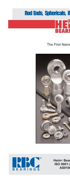
Rod Ends, Sphericals, Rolling Element Bearings - RBC Bearings
Rod Ends, Sphericals, Rolling Element Bearings - RBC Bearings
Rod Ends, Sphericals, Rolling Element Bearings - RBC Bearings

You also want an ePaper? Increase the reach of your titles
YUMPU automatically turns print PDFs into web optimized ePapers that Google loves.
<strong>Rod</strong> <strong>Ends</strong>, <strong>Sphericals</strong>, <strong>Rolling</strong> <strong>Element</strong> <strong>Bearings</strong><br />
The First Name in <strong>Rod</strong> <strong>Ends</strong> TM<br />
Heim ® <strong>Bearings</strong><br />
ISO 9001:2000<br />
AS9100<br />
www.rbcbearings.com<br />
800.390.3300
<strong>RBC</strong> <strong>Bearings</strong> has had a long tradition of innovation, commitment, and<br />
quality since the company was founded in 1919. Today, <strong>RBC</strong> <strong>Bearings</strong><br />
has grown into a world-class manufacturer of standard and customengineered<br />
bearings and related products, with a product focus on<br />
research, testing, and development of the best product for specific<br />
applications.<br />
What We Manufacture<br />
<strong>RBC</strong> <strong>Bearings</strong>, with facilities throughout North America and Europe,<br />
provides bearings and precision products for applications in the construction,<br />
mining, material handling, transportation and off-highway<br />
equipment, robotics and automation, farming, machine tool, and semiconductor<br />
equipment industries. Through <strong>RBC</strong> Aerospace <strong>Bearings</strong>,<br />
the company is a major manufacturer of highly-engineered bearings and<br />
precision products for military, defense, and commercial aerospace<br />
applications.<br />
<strong>RBC</strong>'s high-quality bearings include:<br />
• Heavy Duty Needle Roller <strong>Bearings</strong> - Pitchlign ® caged heavy duty<br />
needle roller bearings, inner rings, type TJ TandemRoller ® bearings for<br />
long life.<br />
• Spherical Plain <strong>Bearings</strong> - Radial, angular, contact, high misalignment,<br />
extended inner ring, DuraLube maintenance-free spherical plain<br />
bearings, QuadLube ® long life bearings, ImpactTuff ® case carburized<br />
bearings, ShimPack ® double-acting angular contact bearings,<br />
CrossLube ® lubrication groove systems, and SpreadLock ® Seal.<br />
• Cam Followers and Yoke Rollers - Standard stud, heavy stud, yoke<br />
type, caged roller followers, <strong>RBC</strong> Roller ® long life cam followers,<br />
HexLube ® universal cam followers, airframe track rollers. Mastguide<br />
rollers and carriage rollers, chain sheaves (for leaf chain), toothless<br />
sprockets (for roller chain), and heavy-duty roller bearing construction.<br />
• <strong>Rod</strong> <strong>Ends</strong> - Commercial and aerospace, precision, Mil-Spec series,<br />
self-lubricating, inch and metric. Heim ® , Unibal ® , and Spherco ® brands.<br />
• Self-Lubricating <strong>Bearings</strong> - Radial, thrust, rod ends, spherical plain<br />
bearings, high temperature, high loads, inch and metric. Fiberglide ®<br />
brand.<br />
• Thin Section Ball <strong>Bearings</strong> - Standard cross sections to one inch.<br />
Sizes to 40 inches. Stainless steel and other materials available. Seals<br />
available on all sizes and standard cross sections. Inch and metric.<br />
• Airframe Control <strong>Bearings</strong> - Ball bearing types, self-lubricating<br />
types, needle rollers, track rollers.<br />
• Ground, Semiground, and Unground Ball <strong>Bearings</strong> - Full complement,<br />
utilizes design and burnished races for higher loads, long life, and<br />
smooth operation.<br />
• Dowel Pins, Loose Needle Rollers, Shafts<br />
• Tapered Roller and Tapered Thrust <strong>Bearings</strong> - Case-hardened and<br />
through-hardened in a variety of sizes, used in Class 8 heavy truck and<br />
trailer wheel bearings, final drive transmissions and gear boxes.<br />
• Large Ball and Cylindrical Roller <strong>Bearings</strong> - Ball and cylindrical<br />
roller bearings up to 60 in. (1.5 m) O.D. Tapered roller and tapered<br />
roller thrust bearings up to 36 in. (9.1 m) O.D. Slewing rings up to<br />
169 in. (4.3 m) O.D.<br />
• Custom Designed <strong>Bearings</strong> - <strong>RBC</strong> produces a wide range of custom<br />
bearings in various materials for specific applications.<br />
Heim ® <strong>Rod</strong> <strong>Ends</strong><br />
Heim ® <strong>Bearings</strong> produces the industry's widest range of rod end types<br />
and sizes (inch and metric). The Heim ® <strong>Bearings</strong> product range<br />
includes rod ends with brass race inserts in standard, precision, and<br />
high capacity designs; high strength two-piece designs; self-lubricating<br />
rod ends with engineered thermoplastic races or Teflon ® liners; and military<br />
standard rod ends for the ultimate in rod end performance. Heim ®<br />
rod ends are also available with a variety of platings, coatings, and<br />
materials, and with a wide range of optional features such as lubrication<br />
fittings, left hand threads, and keyway slots.<br />
Heim ® Spherical <strong>Bearings</strong><br />
Heim ® <strong>Bearings</strong> uses a wide variety of designs and materials to offer a<br />
comprehensive line of spherical bearings. Standard Heim ® spherical<br />
bearing designs include high strength steel-on-steel precision spherical<br />
bearings with brass race inserts; high capacity self-lubricating spherical<br />
bearings with Teflon ® liners; and military standard spherical bearings.<br />
Standard material choices range from plain carbon steel to stainless<br />
steel.<br />
Heim ® Unibal ® Ball <strong>Bearings</strong><br />
The Heim ® <strong>Bearings</strong> unique unground ball bearing is a high capacity<br />
full complement unitized bearing which provides long life and smooth<br />
operation in an economical package. Solid races (not split) which are<br />
unbroken by loading slots provide longer life than other unground ball<br />
bearings and will accommodate thrust loading. Heim ® ball bearings are<br />
available with plain and flanged ODs, and in an extra capacity design.<br />
Heim ® also designs and produces a wide range of special ball bearings.<br />
How We Can Serve You<br />
<strong>RBC</strong> has implemented a total quality control system that uses statistical<br />
quality control at all facilities, and manufactures in high volume to a<br />
just-in-time program.<br />
To serve the ongoing needs of customers, <strong>RBC</strong> has a network of over<br />
1,600 distributors and sales engineers throughout North and South<br />
America and Europe, with authorized agents worldwide. For assistance<br />
with your bearing application, contact:<br />
Warranty<br />
Customer Service - 800.390.3300<br />
<strong>RBC</strong> products are warranted for material and workmanship for a period<br />
not to exceed 90 days from shipment and for a value not to exceed purchase<br />
price. No other warranty is in effect.<br />
Disclaimer and Intellectual Property Statement<br />
The materials comprising this Catalog are provided by <strong>RBC</strong> <strong>Bearings</strong> as a service to its customers<br />
on an "as-is" basis for informational purposes only. <strong>RBC</strong> assumes no responsibility<br />
for any errors or omissions in these materials. <strong>RBC</strong> makes no commitment to update the<br />
information contained herein.<br />
<strong>RBC</strong> makes no, and expressly disclaims any, representations or warranties, express or<br />
implied, regarding the Catalog, including, without limitation, any implied warranties of merchantability<br />
or fitness for a particular purpose. <strong>RBC</strong> makes no, and expressly disclaims any,<br />
warranties, express or implied, regarding the correctness, accuracy, completeness, timeliness,<br />
and reliability of the text, graphics and any other items in the Catalog. Under no circumstances<br />
shall <strong>RBC</strong>, its affiliates, or any of their respective partners, officers, directors,<br />
employees, agents or representatives be liable for any damages, whether direct, indirect,<br />
special or consequential damages for lost revenues, lost profits, or otherwise, arising from or<br />
in connection with this Catalog and the materials contained herein.<br />
All materials contained in the Catalog are protected by copyright laws, and may not be<br />
reproduced, republished, distributed, transmitted, displayed, broadcast or otherwise exploited<br />
in any manner without the express prior written permission of <strong>RBC</strong>.<br />
<strong>RBC</strong>'s names and logos and all related trademarks (including <strong>RBC</strong> Part Numbers, Series<br />
Numbers, and Cone and Cup Numbers), tradenames, and other intellectual property are the<br />
property of <strong>RBC</strong> <strong>Bearings</strong> and cannot be used without its express prior written permission.<br />
TABLE OF CONTENTS<br />
Page No.<br />
<strong>Rod</strong> <strong>Ends</strong><br />
Selection Guide 4-5<br />
HM, HF, HMX G, HFX G, BHM Precision 6-9<br />
HM C, HF C, M CR, F CR Commercial 10-13<br />
CMHD, CFHD Engineered Thermoplastic Race 14-15<br />
HM M, HF M, M M, F M Aircraft 16-19<br />
HME M, HFE M Self-Lubricating 20-21<br />
ME, FE SAE-AS81935 (formerly 22-25<br />
MIL-B-81935)<br />
SM, SMG, SF, SFG Metric Precision 26-27<br />
Technical Section 28-31<br />
Spherical <strong>Bearings</strong><br />
LSS, LS, LHA, LHB, LHSS, COS Precision 32-35<br />
LHSSE, LHSSVV Self-Lubricating 36-37<br />
COM, LH D, LH PP Commercial 38-39<br />
NE, NEG, NEE, NEEG (Narrow) SAE-AS81820 (formerly 40-43<br />
MIL-B-81820)<br />
WE, WEG, WEE, WEEG (Wide) SAE-AS81820 (formerly 44-47<br />
MIL-B-81820)<br />
SS Metric Precision 48<br />
Technical Section 49-50<br />
Sleeve <strong>Bearings</strong><br />
General Information 51<br />
PBE (Plain) SAE-AS81934/1 (formerly 52<br />
MIL-B-81934/1)<br />
FBE (Flanged) SAE-AS81934/2 (formerly 53<br />
MIL-B-81934/2)<br />
Technical Section Self-Lubricating <strong>Bearings</strong> 54<br />
Ball <strong>Bearings</strong><br />
General Information 55<br />
R Standard O.D. 56<br />
RF Flanged O.D. 57<br />
HK A Extra Capacity 58<br />
Applications 59<br />
Special <strong>Bearings</strong> 60-61<br />
Notes 62-63<br />
ROD<br />
ENDS<br />
SPHERICAL<br />
BEARINGS<br />
SLEEVE<br />
BEARINGS<br />
BALL<br />
BEARINGS<br />
SPLS<br />
2<br />
© 1993, 2006, 2009 <strong>RBC</strong> <strong>Bearings</strong> Incorporated. All rights reserved. Teflon ® is a registered trademark of DuPont.
ROD<br />
ENDS<br />
Heim rod ends and spherical plain<br />
bearings are intended for linkage applications<br />
where a bearing must accommodate<br />
significant misalignment. While spherical<br />
plain bearings offer flexibility in housing<br />
and mounting design, the user bears the<br />
responsibility for housing design and the<br />
cost of housing manufacture. <strong>Rod</strong> ends<br />
offer greater mounting convenience and<br />
provide a compact, lightweight, economical<br />
design alternative to the spherical plain<br />
bearing. Heim <strong>Bearings</strong> Company offers<br />
the industry’s widest selection of rod end<br />
types and sizes.<br />
<strong>Rod</strong> End Construction<br />
Heim offers three basic rod end constructions.<br />
The four piece rod end uses race<br />
inserts, typically of brass, to provide<br />
lubricity in the bearing area. This design<br />
offers reduced internal clearance, and<br />
provides smoother operation. It is ideal for<br />
dynamic applications. The two piece rod<br />
end uses a rod end body which is formed<br />
around a spherical ball. The comparatively<br />
heavy cross section of the rod end body in<br />
the two piece design provides high<br />
strength. This makes the two piece rod end<br />
ideal for highly loaded, static applications<br />
where high strength is required. The<br />
cartridge type rod end consists of a<br />
spherical plain bearing mounted in a rod<br />
end body. This design allows the optimum<br />
selection of materials for ball, race and rod<br />
end body. The cartridge type rod end can<br />
also accommodate a PTFE liner for selflubrication.<br />
This design is best suited<br />
for aircraft and military applications<br />
where material selection is a primary<br />
design consideration.<br />
Self-lubricating <strong>Rod</strong>s <strong>Ends</strong><br />
Heim produces metal-to-metal rod ends<br />
and self-lubricating rod ends. All metal-tometal<br />
rod ends, including brass insert four<br />
piece types, require regular lubrication.<br />
This can be accomplished by splash or<br />
immersion oil lubrication, or by greasing<br />
through optional lubricators (grease fittings).<br />
Self-lubricating types are used<br />
where relubrication is not practical, or in<br />
applications where relubrication is not<br />
desirable, such as on food processing<br />
machinery or in clean environments. Heim<br />
self-lubricating rods ends are available with<br />
bonded PTFE fabric liners, or with molded,<br />
engineered thermoplastic race inserts.<br />
<strong>Rod</strong> End Grades<br />
Heim rod ends are offered in four grades:<br />
precision, commercial, aircraft, and<br />
military. Precision rod ends are manufactured<br />
to tight tolerances for applications<br />
requiring improved linkage accuracy and<br />
reduced looseness. Commercial rod ends<br />
are produced using standard materials<br />
and manufacturing methods, and are an<br />
economical choice for industrial applications.<br />
Aircraft rod ends use premium<br />
materials, and have magnafluxed rod end<br />
bodies. Originally intended for aircraft<br />
applications, aircraft rod ends are used in<br />
many industrial applications where a high<br />
degree of reliability is required. Military<br />
rod ends are produced in strict accordance<br />
with all applicable military specifications<br />
and are typically used in military<br />
and commercial aviation applications, or<br />
when Mil-Spec approval is required.<br />
Precision <strong>Rod</strong> <strong>Ends</strong> Grade HM and HF four<br />
piece precision rod ends use brass race<br />
inserts for lubricity and clearance control.<br />
They are produced to tight tolerances for<br />
applications requiring a more precise rod<br />
end; for example, a linkage where positioning<br />
accuracy is essential. These rod end<br />
bodies and balls are plated for corrosion<br />
resistance. Series BHM, HFX G and<br />
HMX G four piece precision extra capacity<br />
rod ends are the high strength series<br />
intended for more heavily loaded, static and<br />
dynamic industrial applications. These rod<br />
ends have heat treated bodies for increased<br />
strength and aluminum bronze race inserts<br />
for high bearing capacity. The rod end<br />
bodies are protective coated for corrosion<br />
resistance and the balls are chrome plated<br />
for superior wear and corrosion resistance.<br />
Series BHM (male) and series HFX G<br />
(female) have common thread sizes. Series<br />
HMX G (male) have oversized shanks for<br />
additional shank strength.<br />
•Series HM and HF: pages 6-7<br />
•Series BHM, HFX G<br />
and HMX G: pages 8-9<br />
HEIM UNIBAL ® ROD ENDS<br />
Series<br />
Size Range<br />
HM, HF<br />
3/16" to 1"<br />
BHM,<br />
HFX G,<br />
HMX G<br />
1/4" to 3/4"<br />
HM C, HF C<br />
3/16" to 3/4"<br />
M CR, F CR<br />
3/16" to 3/4"<br />
CMHD,<br />
CFHD<br />
3/16" to 3/4"<br />
ROD END QUICK SELECTION GUIDE<br />
Product<br />
Features<br />
Precision Grade<br />
Brass Inserts<br />
Four Piece<br />
Construction<br />
Precision Grade<br />
Aluminum Bronze<br />
Inserts, High<br />
Strength Body,<br />
Four Piece<br />
Construction<br />
Commercial Grade<br />
Brass Inserts<br />
Four Piece<br />
Construction<br />
Commercial Grade<br />
Two Piece<br />
Construction<br />
Commercial Grade<br />
Self Lubricating<br />
Thermoplastic Race,<br />
Maximum<br />
Temperature 125°F<br />
Customer<br />
Benefits<br />
Low Friction,<br />
Long Dynamic<br />
Life, Smooth Feel,<br />
Good Conformity<br />
High Capacity<br />
Version<br />
Low Friction,<br />
Long Dynamic<br />
Life, Smooth Feel,<br />
Good Conformity<br />
High Loads,<br />
Reversing Loads,<br />
Shock Loads,<br />
Cost Effective<br />
Maintenance Free<br />
Common<br />
Applications<br />
Control Linkages,<br />
For Reduced Play,<br />
Accelerator<br />
Linkages<br />
Heavy Duty<br />
Applications<br />
Packaging<br />
Machine Linkages<br />
Brake and Clutch<br />
Pedals For Heavy<br />
Machinery,<br />
Satellite Dish<br />
Controls<br />
Food Processing,<br />
Paper Machinery,<br />
Bus Door<br />
Closures<br />
COMMERCIAL AND PRECISION<br />
AIRCRAFT AND MILITARY<br />
HEIM<br />
SERIES<br />
HM<br />
HF<br />
BHM<br />
HFX G<br />
HMX G<br />
HM C<br />
HF C<br />
M CR<br />
F CR<br />
CMHD<br />
CFHD<br />
HM M<br />
HF M<br />
M M<br />
F M<br />
HME M<br />
HFE M<br />
ME<br />
FE<br />
Best<br />
Better<br />
Good<br />
✔ Yes<br />
PAGE<br />
4-7<br />
4-7<br />
8-11<br />
8-11<br />
12-13<br />
14-17<br />
14-17<br />
18-19<br />
20-23<br />
LOADING<br />
STATIC<br />
OSCILLATING<br />
REVERSING<br />
SHOCK<br />
PRECISION<br />
CORROSION<br />
RESISTANCE<br />
SELF-LUBRICATING<br />
MIL-SPEC MIL-B-81935<br />
MAXIMUM<br />
TEMPERATURE<br />
Commercial <strong>Rod</strong> <strong>Ends</strong> Series HM C and<br />
HF C four piece commercial rod ends use<br />
Heim’s classic brass race insert design for<br />
lubricity and clearance control. These rod<br />
ends are preferred for dynamic applications.<br />
Heim commercial rod ends have zinc plated<br />
bodies and nickel plated balls for corrosion<br />
resistance. Series M CR and F CR two piece<br />
commercial rod ends offer high strength for<br />
heavy static loads. Heim’s unique manufacturing<br />
process for two piece rod ends yields<br />
the industry’s best conformity between ball<br />
and body for maximum bearing capacity.<br />
• Series HM C and HF C: pages 10-11<br />
• Series M CR and F CR: pages 12-13<br />
Series CMHD & CFHD self-lubricating commercial<br />
rod ends use an engineered thermoplastic<br />
race for applications where relubrication<br />
is not practical or desirable. The rod end<br />
body and ball are plated for corrosion resistance.<br />
This series is also available in stainless<br />
steel for superior corrosion resistance.<br />
• Series CMHD and CFHD: page 15<br />
✔<br />
✔<br />
✔<br />
✔<br />
✔<br />
✔<br />
✔<br />
✔<br />
✔<br />
✔<br />
250°F 250°F 250°F<br />
250°F<br />
125°F<br />
350°F 250°F 250°F 250°F<br />
SIZE<br />
RANGE<br />
3/16"<br />
to<br />
1"<br />
1/4"<br />
to<br />
3/4"<br />
3/16"<br />
to<br />
3/4"<br />
3/16"<br />
to<br />
3/4"<br />
3/16"<br />
to<br />
3/4"<br />
1/8"<br />
to<br />
1"<br />
3/16"<br />
to<br />
1/4"<br />
3/16"<br />
to<br />
1"<br />
3/16"<br />
to<br />
1"<br />
RACE<br />
MATERIAL<br />
BRASS<br />
ALUMINUM<br />
BRONZE<br />
BRASS<br />
STEEL<br />
THERMO-<br />
PLASTIC<br />
BRASS<br />
BRASS<br />
PTFE<br />
PTFE<br />
DESIGN<br />
FOUR PIECE<br />
TWO PEICE<br />
MOLDED<br />
RACE<br />
FOUR PIECE<br />
CARTRIDGE<br />
Aircraft <strong>Rod</strong> <strong>Ends</strong> Series HM M and HF<br />
M four piece aircraft rod ends have<br />
magnafluxed rod end bodies for a high<br />
degree of assurance of rod end integrity.<br />
The bearing surface is a chrome plated ball<br />
on brass race inserts. This series was<br />
originally intended for general aviation<br />
applications and is also used in many<br />
industrial applications where rod end<br />
reliability is critical. Series M M and F M<br />
special purpose aircraft rod ends use<br />
materials and construction identical to<br />
series HM M and HF M but have different<br />
dimensions. Series HME M and HFE M self<br />
lubricating aircraft rod ends use Heim’s<br />
UNIFLON ® PTFE liner and cartridge type<br />
construction. The Heim UNIFLON ® PTFE<br />
liner is approved to SAE-AS81820 (formerly<br />
MIL-B-18820).<br />
• Series HM M and HF M: pages 16-17<br />
• Series M M and F M: pages 18-19<br />
• Series HME M and HFE M: pages 20-21<br />
Military <strong>Rod</strong> <strong>Ends</strong> Series ME and FE milspec<br />
rod ends use Heim’s Type E UNIFLON ®<br />
PTFE liner and cartridge type construction.<br />
<strong>Rod</strong> end bodies are made from 4340 alloy<br />
steel, heat treated to SAE-AMS-H-6875<br />
(formerly MIL-H-6875), and are cadmium<br />
plated. The outer races are made from<br />
heat treated 17-4PH stainless steel (ASM<br />
5643). The balls are made from heat<br />
treated 440C stainless steel (AMS 5630).<br />
The Heim UNIFLON ® PTFE liner is approved<br />
to SAE-AS81820 (formerly MIL-<br />
B-81820). The ME and FE series mil-spec<br />
aircraft rod ends are approved to SAE-<br />
AS81935 (formerly MIL-B-81935). These<br />
premium rod ends are primarily intended<br />
for use in commercial and military<br />
aviation applications.<br />
• Series ME: pages 22-23<br />
• Series FE: pages 24-25<br />
Metric <strong>Rod</strong> <strong>Ends</strong> Series SM, SMG, SF and<br />
SFG four piece, precision, metric rod ends<br />
use brass race inserts for lubricity and<br />
clearance control. They are produced to<br />
tight tolerances for applications where a<br />
precision rod end is required in a metric<br />
size. The two piece construction offers the<br />
added benefit of high strength for high<br />
loads. Heim also offers a wide variety of<br />
other metric rod ends. Contact Heim for<br />
availability and specifications.<br />
• Series SMG and SFG: Pages 26-27<br />
Optional <strong>Rod</strong> End Features<br />
Heim rod ends are available with male<br />
and female threaded shanks. Standard<br />
rod ends have right hand threads. Left<br />
hand threads are available as an option.<br />
Lubricators are standard on selected series<br />
and are available as an option on all<br />
other series. Shank keyways are optionally<br />
available on most series to engage<br />
lock washer tangs. A wide range of<br />
other optional features includes plain<br />
shanks and special plating.<br />
ROD<br />
ENDS<br />
4<br />
5
Precision Series<br />
Four Piece - Metal-to-Metal<br />
Precision Series<br />
Four Piece - Metal-to-Metal<br />
D<br />
W<br />
H<br />
D<br />
W<br />
H<br />
ROD<br />
ENDS<br />
E<br />
O<br />
B<br />
E O B<br />
ROD<br />
ENDS<br />
LUBRICATOR<br />
OPTIONAL<br />
LUBRICATOR<br />
OPTIONAL<br />
F<br />
F<br />
A<br />
A<br />
L<br />
Series HM<br />
ROD END<br />
NUMBER<br />
HM3<br />
HM4<br />
HM5<br />
HM6<br />
HM7<br />
HM8<br />
HM10<br />
HM12<br />
HM16❻<br />
DIMENSIONS IN INCHES<br />
MAXIMUM<br />
LENGTH TO<br />
BALL STATIC<br />
BALL HOUSING HEAD CENTER THREAD THREAD BALL FLAT RADIAL APPROX<br />
BORE WIDTH WIDTH DIAMETER OF BALL LENGTH SIZE DIAMETER DIAMETER LOAD ➐ WEIGHT<br />
B<br />
W H D F A M E O<br />
+.0015 +.000 +.005 +.010 +.031 +.062<br />
- .0005 - .005 - .005 - .010 - .031 - .031 UNF-3A REF REF LBF LBS<br />
.1900<br />
.2500<br />
.3125<br />
.3750<br />
.4375<br />
.5000<br />
.6250<br />
.7500<br />
1.0000<br />
.312<br />
.375<br />
.437<br />
.500<br />
.562<br />
.625<br />
.750<br />
.875<br />
1.375<br />
.250<br />
.281<br />
.344<br />
.406<br />
.437<br />
.500<br />
.562<br />
.687<br />
1.000 ➎<br />
.625<br />
.750<br />
.875<br />
1.000<br />
1.125<br />
1.312<br />
1.500<br />
1.750<br />
2.750<br />
1.250<br />
1.562<br />
1.875<br />
1.938<br />
2.125<br />
2.438<br />
2.625<br />
2.875<br />
4.125<br />
Outer Member: Carbon steel, with protective coating for corrosion resistance<br />
Ball:<br />
52100 Alloy steel, heat treated, and chrome plated<br />
Inserts: Brass<br />
➎<br />
.750<br />
1.000<br />
1.250<br />
1.250<br />
1.375<br />
1.500<br />
1.625<br />
1.750<br />
2.125<br />
.1900-32<br />
.2500-28<br />
.3125-24<br />
.3750-24<br />
.4375-20<br />
.5000-20<br />
.6250-18<br />
.7500-16<br />
1.2500-12<br />
.437<br />
.515<br />
.625<br />
.718<br />
.812<br />
.937<br />
1.125<br />
1.312<br />
1.875<br />
.306<br />
.353<br />
.447<br />
.516<br />
.586<br />
.698<br />
.839<br />
.978<br />
1.275<br />
M<br />
900<br />
1,700<br />
2,500<br />
4,000<br />
5,000<br />
7,000<br />
8,050<br />
11,300<br />
28,400<br />
.03<br />
.05<br />
.08<br />
.12<br />
.17<br />
.26<br />
.41<br />
.64<br />
2.25<br />
NOTES<br />
❶ Add letter “L” to prefix to indicate Left Hand thread<br />
Example: HML4<br />
❷ For design options, see page 31<br />
❸ For Engineering data, see pages 28 thru 30<br />
❹ “H” tolerance across inserts is +/-.015<br />
➎ Tolerances for 16 size: “D” +.030<br />
- .010<br />
“H” +.030<br />
-.010<br />
❻ Outer Member: Alloy steel<br />
Inserts: One piece carbon steel race<br />
➐ Load ratings reflect loads without lubricator.<br />
For loads with lubricator contact Heim<br />
Engineering.<br />
Series HF<br />
ROD END<br />
NUMBER<br />
HF3<br />
HF4<br />
HF5<br />
HF6<br />
HF7<br />
HF8<br />
HF10<br />
HF12<br />
HF16 ❻<br />
BORE<br />
+.0015<br />
- .0005<br />
.1900<br />
.2500<br />
.3125<br />
.3750<br />
.4375<br />
.5000<br />
.6250<br />
.7500<br />
1.0000<br />
BALL<br />
WIDTH<br />
HOUSING<br />
WIDTH<br />
HEAD<br />
DIAMETER<br />
LENGTH TO<br />
CENTER OF<br />
BALL<br />
DIMENSIONS IN INCHES<br />
B W H D F M<br />
+.000<br />
- .005<br />
+.005<br />
- .005<br />
+.010<br />
- .010<br />
+.031<br />
- .031<br />
+.062<br />
Outer Member: Carbon steel, with protective coating for corrosion resistance<br />
Ball:<br />
Inserts:<br />
52100 Alloy steel, heat treated, and chrome plated<br />
Brass<br />
.312<br />
.375<br />
.437<br />
.500<br />
.562<br />
.625<br />
.750<br />
.875<br />
1.375<br />
.250<br />
.281<br />
.344<br />
.406<br />
.437<br />
.500<br />
.562<br />
.687<br />
1.000➎<br />
.625<br />
.750<br />
.875<br />
1.000<br />
1.125<br />
1.312<br />
1.500<br />
1.750<br />
2.750➎<br />
1.062<br />
1.312<br />
1.375<br />
1.625<br />
1.812<br />
2.125<br />
2.500<br />
2.875<br />
4.125<br />
K<br />
BALL<br />
FLAT<br />
ACROSS<br />
WRENCH<br />
THREAD THREAD BALL<br />
OTHER<br />
LENGTH SIZE DIAMETER DIAMETER FLATS DIMENSIONS LOAD➐<br />
A E O J K L<br />
- .031 UNF-3B REF REF<br />
+.010<br />
- .010<br />
+.010<br />
- .010<br />
+.010<br />
- .010 LBF<br />
.562<br />
.750<br />
.750<br />
.937<br />
1.062<br />
1.187<br />
1.500<br />
1.750<br />
2.125<br />
.1900-32<br />
.2500-28<br />
.3125-24<br />
.3750-24<br />
.4375-20<br />
.5000-20<br />
.6250-18<br />
.7500-16<br />
1.2500-12<br />
.437<br />
.515<br />
.625<br />
.718<br />
.812<br />
.937<br />
1.125<br />
1.312<br />
1.875<br />
.306<br />
.353<br />
.447<br />
.516<br />
.586<br />
.698<br />
.839<br />
.978<br />
1.275<br />
.312<br />
.375<br />
.437<br />
.562<br />
.625<br />
.750<br />
.875<br />
1.000<br />
1.500➎<br />
.406<br />
.468<br />
.500<br />
.687<br />
.750<br />
.875<br />
1.000<br />
1.125<br />
1.625➎<br />
.187<br />
.187<br />
.187<br />
.250<br />
.250<br />
.250<br />
.312<br />
.312<br />
.437➎<br />
M<br />
NOTES<br />
❶ Add letter “L” to prefix to indicate Left Hand thread<br />
Example: HFL 4<br />
❷ For design options, see page 31<br />
❸ For Engineering data, see pages 28 thru 30<br />
❹ “H” tolerance across inserts is +/-.015<br />
➎ Tolerances for 16 size: “D” +.030<br />
- .010<br />
“H” +.030<br />
-.010<br />
“K”, “J”, “L” +/-.015<br />
❻ Outer Member: Alloy steel<br />
Inserts: One piece carbon steel race<br />
➐ Load ratings reflect loads without lubricator.<br />
For loads with lubricator contact Heim<br />
Engineering.<br />
J<br />
MAXIMUM<br />
STATIC<br />
RADIAL<br />
1,850<br />
2,700<br />
3,350<br />
4,450<br />
5,350<br />
7,400<br />
8,050<br />
11,300<br />
28,400<br />
APPROX<br />
WEIGHT<br />
LBS<br />
.03<br />
.05<br />
.08<br />
.12<br />
.17<br />
.26<br />
.41<br />
.64<br />
2.25<br />
6<br />
7
Precision Extra Capacity Series<br />
Four Piece - Metal-to-Metal<br />
D<br />
W<br />
H<br />
Precision Extra Capacity Series<br />
Four Piece - Metal-to-Metal<br />
D<br />
W<br />
H<br />
E O B<br />
E<br />
O<br />
B<br />
ROD<br />
ENDS<br />
F<br />
➎<br />
LUBRICATOR<br />
OPTIONAL<br />
A<br />
F<br />
N<br />
➎ ➏<br />
LUBRICATOR<br />
INSPECTION<br />
HOLE<br />
L<br />
A<br />
ROD<br />
ENDS<br />
Series HMX G<br />
M<br />
Series HFX G<br />
K<br />
M<br />
J<br />
ROD END<br />
NUMBER<br />
HMX4G<br />
HMX5G<br />
HMX6G<br />
HMX7G<br />
HMX8G<br />
HMX10G<br />
HMX12G<br />
BORE<br />
B<br />
+.0015<br />
- .0005<br />
.2500<br />
.3125<br />
.3750<br />
.4375<br />
.5000<br />
.6250<br />
.7500<br />
DIMENSIONS IN INCHES<br />
LENGTH TO<br />
BALL<br />
BALL HOUSING HEAD CENTER OF THREAD THREAD BALL FLAT<br />
WIDTH WIDTH DIAMETER BALL LENGTH SIZE DIAMETER DIAMETER<br />
W H D F A M E O<br />
+.000<br />
- .005<br />
+.005<br />
- .005<br />
+.010<br />
- .010<br />
+.010<br />
- .010<br />
+.062<br />
- .031 UNF -3A REF REF<br />
.375<br />
.437<br />
.500<br />
.562<br />
.625<br />
.750<br />
.875<br />
.281<br />
.344<br />
.406<br />
.437<br />
.500<br />
.562<br />
.687<br />
.750<br />
.875<br />
1.000<br />
1.125<br />
1.312<br />
1.500<br />
1.750<br />
1.562<br />
1.875<br />
1.938<br />
2.125<br />
2.438<br />
2.625<br />
2.875<br />
1.000<br />
1.250<br />
1.250<br />
1.375<br />
1.500<br />
1.625<br />
1.750<br />
.3125-24<br />
.3750-24<br />
.4375-20<br />
.5000-20<br />
.6250-18<br />
.7500-16<br />
.8750-14<br />
.515<br />
.625<br />
.718<br />
.812<br />
.937<br />
1.125<br />
1.312<br />
.353<br />
.447<br />
.516<br />
.586<br />
.698<br />
.839<br />
.978<br />
MAXIMUM<br />
STATIC<br />
RADIAL<br />
LOAD<br />
WITH WITHOUT<br />
LUBRICATOR LUBRICATOR<br />
LBF<br />
3,260<br />
4,920<br />
7,240<br />
7,620<br />
11,920<br />
13,940<br />
21,570<br />
6,680<br />
8,410<br />
11,160<br />
13,660<br />
19,340<br />
21,080<br />
29,800<br />
APPROX<br />
WEIGHT<br />
LBS<br />
.06<br />
.09<br />
.13<br />
.18<br />
.30<br />
.46<br />
.72<br />
BORE<br />
B<br />
ROD END<br />
NUMBER +.0015<br />
- .0005<br />
HFX4G<br />
HFX5G<br />
HFX6G<br />
HFX7G<br />
HFX8G<br />
HFX10G<br />
HFX12G<br />
.2500<br />
.3125<br />
.3750<br />
.4375<br />
.5000<br />
.6250<br />
.7500<br />
BALL<br />
WIDTH<br />
W<br />
+.000<br />
- .005<br />
.375<br />
.437<br />
.500<br />
.562<br />
.625<br />
.750<br />
.875<br />
DIMENSIONS IN INCHES<br />
LENGTH TO<br />
BALL<br />
HOUSING HEAD CENTER OF THREAD THREAD BALL FLAT<br />
WIDTH DIAMETER BALL LENGTH SIZE DIAMETER DIAMETER<br />
H D F A M E O<br />
+.005 +.010 +.010 +.062<br />
- .005 - .010 - .010 - .031 UNF -3B REF REF<br />
.281<br />
.344<br />
.406<br />
.437<br />
.500<br />
.562<br />
.687<br />
.750<br />
.875<br />
1.000<br />
1.125<br />
1.312<br />
1.500<br />
1.750<br />
1.312<br />
1.375<br />
1.625<br />
1.812<br />
2.125<br />
2.500<br />
2.875<br />
.750<br />
.750<br />
.937<br />
1.062<br />
1.187<br />
1.500<br />
1.750<br />
.2500-28<br />
.3125-24<br />
.3750-24<br />
.4375-20<br />
.5000-20<br />
.6250-18<br />
.7500-16<br />
.515<br />
.625<br />
.718<br />
.812<br />
.937<br />
1.125<br />
1.312<br />
.355<br />
.447<br />
.517<br />
.586<br />
.698<br />
.839<br />
.978<br />
ACROSS<br />
WRENCH<br />
FLATS<br />
J<br />
+.010<br />
- .010<br />
.375<br />
.437<br />
.562<br />
.625<br />
.750<br />
.875<br />
1.000<br />
K<br />
+.010<br />
- .010<br />
.468<br />
.500<br />
.687<br />
.750<br />
.875<br />
1.000<br />
1.125<br />
OTHER<br />
DIMENSIONS<br />
N<br />
+.020<br />
- .020<br />
.312<br />
.406<br />
.469<br />
.531<br />
.594<br />
.750<br />
.875<br />
L<br />
+.010<br />
- .010<br />
.187<br />
.187<br />
.250<br />
.250<br />
.250<br />
.312<br />
.312<br />
MAXIMUM<br />
STATIC<br />
RADIAL<br />
LOAD<br />
LBF<br />
6,680<br />
8,410<br />
11,160<br />
13,660<br />
19,340<br />
21,080<br />
29,800<br />
APPROX<br />
WEIGHT<br />
LBS<br />
.06<br />
.08<br />
.14<br />
.18<br />
.29<br />
.43<br />
.64<br />
Outer Member: 4130 or 4340 Alloy steel, heat treated, magnetic particle<br />
inspected, with protective coating for corrosion resistance<br />
Ball:<br />
Inserts:<br />
52100 Alloy steel, heat treated, chrome plated<br />
Copper alloy<br />
Series BHM<br />
ROD END<br />
NUMBER<br />
BHM4<br />
BHM5<br />
BHM6<br />
BHM7<br />
BHM8<br />
BHM10<br />
BHM12<br />
BALL<br />
WIDTH<br />
HOUSING<br />
WIDTH<br />
DIMENSIONS IN INCHES<br />
HEAD<br />
DIAMETER<br />
LENGTH TO<br />
CENTER OF<br />
BALL<br />
THREAD<br />
LENGTH<br />
NOTES<br />
❶ Add letter “L” to prefix to indicate Left Hand thread<br />
Example: HMXL4G<br />
❷ For design options, see page 31<br />
❸ For Engineering data, see pages 28 thru 30<br />
❹ “H” tolerance across inserts is +/-.015<br />
➎ Delete letter “G” from suffix to indicate no lubricator<br />
Example: HMX4<br />
THREAD<br />
SIZE<br />
BALL<br />
DIAMETER<br />
BALL<br />
FLAT<br />
DIAMETER<br />
BORE<br />
B W H D F A M<br />
E O<br />
+.0015<br />
- .0005<br />
+.000<br />
- .005<br />
+.005<br />
- .005<br />
+.010<br />
- .010<br />
+.010<br />
- .010<br />
+.062<br />
- .031 UNF-3A REF REF<br />
.2500<br />
.3125<br />
.3750<br />
.4375<br />
.5000<br />
.6250<br />
.7500<br />
.375<br />
.437<br />
.500<br />
.562<br />
.625<br />
.750<br />
.875<br />
.281<br />
.344<br />
.406<br />
.437<br />
.500<br />
.562<br />
.687<br />
.750<br />
.875<br />
1.000<br />
1.125<br />
1.312<br />
1.500<br />
1.750<br />
1.562<br />
1.875<br />
1.938<br />
2.125<br />
2.438<br />
2.625<br />
2.875<br />
1.000<br />
1.250<br />
1.250<br />
1.375<br />
1.500<br />
1.625<br />
1.750<br />
.2500 - 28<br />
.3125 - 24<br />
.3750 - 24<br />
.4375 - 20<br />
.5000 - 20<br />
.6250 - 18<br />
.7500 - 16<br />
.515<br />
.625<br />
.718<br />
.812<br />
.937<br />
1.125<br />
1.312<br />
.353<br />
.447<br />
.516<br />
.586<br />
.698<br />
.839<br />
.978<br />
MAXIMUM<br />
STATIC<br />
RADIAL<br />
LOAD<br />
WITHOUT<br />
LUBRICATOR<br />
LBF<br />
4,290<br />
6,880<br />
10,500<br />
13,660<br />
19,340<br />
21,080<br />
29,800<br />
APPROX<br />
WEIGHT<br />
LBS<br />
.05<br />
.08<br />
.12<br />
.17<br />
.26<br />
.41<br />
.64<br />
Outer Member: 4130 or 4340 Alloy steel, heat treated, magnetic particle<br />
inspected, with protective coating for corrosion resistance<br />
Ball:<br />
Inserts:<br />
52100 Alloy steel, heat treated, chrome plated<br />
Copper alloy<br />
NOTES<br />
❶ Add letter “L” to prefix to indicate Left Hand thread.<br />
Example: HFXL4G<br />
❷ For design options, see page 31<br />
❸ For Engineering data, see pages 28 thru 30<br />
❹ “H” tolerance across inserts is +/-.015<br />
➎ Lubricator standard on HFX G Series<br />
➏ Delete letter “G” from suffix on HFX G Series to indicate no lubricator<br />
Example: HFX4<br />
8<br />
Outer Member: 4130 or 4340 Alloy steel, heat treated, magnetic particle<br />
inspected, with protective coating for corrosion resistance<br />
Ball:<br />
Inserts:<br />
52100 Alloy steel, heat treated, chrome plated<br />
Copper alloy<br />
NOTES<br />
❶ Add letter “L” to prefix to indicate Left Hand thread<br />
Example: BHML4<br />
❷ For design options, see page 31<br />
❸ For Engineering data, see pages 28 thru 30<br />
❹ “H” tolerance across inserts is +/-.015<br />
➎ Lubricator optional on BHM series<br />
Example: BHM4G<br />
9
Commercial Series<br />
Four Piece - Metal-to-Metal<br />
Commercial Series<br />
Four Piece - Metal-to-Metal<br />
D<br />
W<br />
H<br />
D<br />
W<br />
H<br />
ROD<br />
ENDS<br />
E<br />
O<br />
B<br />
E<br />
O<br />
B<br />
ROD<br />
ENDS<br />
F<br />
LUBRICATOR<br />
OPTIONAL<br />
F<br />
LUBRICATOR<br />
OPTIONAL<br />
A<br />
A<br />
L<br />
Series HM C<br />
ROD END<br />
NUMBER<br />
HM3C<br />
HM4C<br />
HM5C<br />
HM6C<br />
HM7C<br />
HM8C<br />
HM10C<br />
HM12C<br />
BORE<br />
BALL<br />
WIDTH<br />
HOUSING<br />
WIDTH<br />
DIMENSIONS IN INCHES<br />
HEAD<br />
DIAMETER<br />
LENGTH TO<br />
CENTER OF<br />
BALL<br />
THREAD<br />
LENGTH<br />
THREAD<br />
SIZE<br />
BALL<br />
DIAMETER<br />
BALL FLAT<br />
DIAMETER<br />
B W H D F A M E O<br />
+.0025<br />
- .0005<br />
+.005<br />
- .005<br />
+.010<br />
- .010<br />
+.031<br />
- .031<br />
+.031<br />
- .031<br />
+.062<br />
- .062 UNF -3A REF REF<br />
.1900<br />
.2500<br />
.3125<br />
.3750<br />
.4375<br />
.5000<br />
.6250<br />
.7500<br />
.312<br />
.375<br />
.437<br />
.500<br />
.562<br />
.625<br />
.750<br />
.875<br />
.250<br />
.281<br />
.344<br />
.406<br />
.437<br />
.500<br />
.562<br />
.687<br />
.625<br />
.750<br />
.875<br />
1.000<br />
1.125<br />
1.312<br />
1.500<br />
1.750<br />
1.250<br />
1.562<br />
1.875<br />
1.938<br />
2.125<br />
2.438<br />
2.625<br />
2.875<br />
.750<br />
1.000<br />
1.250<br />
1.250<br />
1.375<br />
1.500<br />
1.625<br />
1.750<br />
.1900 - 32<br />
.2500 - 28<br />
.3125 - 24<br />
.3750 - 24<br />
.4375 - 20<br />
.5000 - 20<br />
.6250 - 18<br />
.7500 - 16<br />
.437<br />
.515<br />
.625<br />
.718<br />
.812<br />
.937<br />
1.125<br />
1.312<br />
.306<br />
.353<br />
.447<br />
.516<br />
.586<br />
.698<br />
.839<br />
.978<br />
M<br />
MAXIMUM<br />
STATIC<br />
RADIAL<br />
LOAD<br />
LBF<br />
900<br />
1,700<br />
2,500<br />
4,000<br />
5,000<br />
7,000<br />
8,050<br />
11,300<br />
APPROX<br />
WEIGHT<br />
LBS<br />
.03<br />
.05<br />
.08<br />
.12<br />
.17<br />
.25<br />
.41<br />
.64<br />
Series HF C<br />
ROD END<br />
NUMBER<br />
HF3C<br />
HF4C<br />
HF5C<br />
HF6C<br />
HF7C<br />
HF8C<br />
HF10C<br />
HF12C<br />
BORE<br />
B<br />
+.0025<br />
- .0005<br />
.1900<br />
.2500<br />
.3125<br />
.3750<br />
.4375<br />
.5000<br />
.6250<br />
.7500<br />
DIMENSIONS IN INCHES<br />
LENGTH TO<br />
BALL ACROSS<br />
BALL HOUSING HEAD CENTER OF THREAD THREAD BALL FLAT WRENCH<br />
OTHER<br />
WIDTH WIDTH DIAMETER BALL LENGTH SIZE DIAMETER DIAMETER FLATS DIMENSIONS<br />
W H D F A M E O J K L<br />
+.005<br />
- .005<br />
+.010<br />
- .010<br />
+.031<br />
- .031<br />
+.031<br />
- .031<br />
+.062<br />
- .062 UNF-3B REF REF<br />
+.010<br />
- .010<br />
+.010<br />
- .010<br />
+.010<br />
- .010<br />
.312<br />
.375<br />
.437<br />
.500<br />
.562<br />
.625<br />
.750<br />
.875<br />
.250<br />
.281<br />
.344<br />
.406<br />
.437<br />
.500<br />
.562<br />
.687<br />
.625<br />
.750<br />
.875<br />
1.000<br />
1.125<br />
1.312<br />
1.500<br />
1.750<br />
1.062<br />
1.312<br />
1.375<br />
1.625<br />
1.812<br />
2.125<br />
2.500<br />
2.875<br />
.562<br />
.750<br />
.750<br />
.937<br />
1.062<br />
1.187<br />
1.500<br />
1.750<br />
.1900-32<br />
.2500-28<br />
.3125-24<br />
.3750-24<br />
.4375-20<br />
.5000-20<br />
.6250-18<br />
.7500-16<br />
K<br />
.437<br />
.515<br />
.625<br />
.718<br />
.812<br />
.937<br />
1.125<br />
1.312<br />
.306<br />
.353<br />
.447<br />
.516<br />
.586<br />
.698<br />
.839<br />
.978<br />
.312<br />
.375<br />
.437<br />
.562<br />
.625<br />
.750<br />
.875<br />
1.000<br />
.406<br />
.468<br />
.500<br />
.687<br />
.750<br />
.875<br />
1.000<br />
1.125<br />
.187<br />
.187<br />
.187<br />
.250<br />
.250<br />
.250<br />
.312<br />
.312<br />
M<br />
J<br />
MAXIMUM<br />
STATIC<br />
RADIAL<br />
LOAD<br />
LBF<br />
1,850<br />
2,700<br />
3,350<br />
4,450<br />
5,350<br />
7,400<br />
8,050<br />
11,300<br />
APPROX<br />
WEIGHT<br />
LBS<br />
.03<br />
.05<br />
.08<br />
.12<br />
.17<br />
.26<br />
.41<br />
.64<br />
Outer Member: Carbon steel, with protective coating for corrosion resistance<br />
Ball: 52100 Alloy steel, heat treated, chrome plated<br />
Inserts: Brass<br />
NOTES<br />
❶ Add letter “L” to prefix to indicate Left Hand thread<br />
Example: HML4C<br />
❷ For design options, see page 31<br />
❸ For Engineering data, see pages 28 thru 30<br />
❹ “H” tolerance across inserts is +/-.015<br />
Outer Member: Carbon steel, with protective coating for corrosion resistance<br />
Ball: 52100 Alloy steel, heat treated, chrome plated<br />
Inserts: Brass<br />
NOTES<br />
❶ Add letter “L” to prefix to indicate Left Hand thread<br />
Example: HFL4C<br />
❷ For design options, see page 31<br />
❸ For Engineering data, see pages 28 thru 30<br />
❹ “H” tolerance across inserts is +/-.015<br />
10<br />
11
Commercial Extra Capacity Series<br />
Two Piece - Metal-to-Metal<br />
Commercial Extra Capacity Series<br />
Two Piece - Metal-to-Metal<br />
D<br />
ROD<br />
ENDS<br />
ROD<br />
ENDS<br />
F<br />
LUBRICATOR<br />
OPTIONAL<br />
Series M CR<br />
Series F CR<br />
ROD END<br />
NUMBER<br />
M3CR<br />
M4CR<br />
M5CR<br />
M6CR<br />
M7CR<br />
M8CR<br />
M10CR<br />
M12CR<br />
DIMENSIONS IN INCHES<br />
LENGTH TO<br />
BALL HOUSING HEAD CENTER OF THREAD THREAD BALL BALL FLAT<br />
BORE WIDTH WIDTH DIAMETER BALL LENGTH SIZE DIAMETER DIAMETER<br />
B W H D F A M E O<br />
+.0025<br />
- .0005<br />
.1900<br />
.2500<br />
.3125<br />
.3750<br />
.4375<br />
.5000<br />
.6250<br />
.7500<br />
+.005<br />
- .005<br />
.312<br />
.375<br />
.437<br />
.500<br />
.562<br />
.625<br />
.750<br />
.875<br />
+.010<br />
- .010<br />
.250<br />
.281<br />
.344<br />
.406<br />
.437<br />
.500<br />
.562<br />
.687<br />
+.031<br />
- .031<br />
.625<br />
.750<br />
.875<br />
1.000<br />
1.125<br />
1.312<br />
1.500<br />
1.750<br />
+.031<br />
- .031<br />
1.250<br />
1.562<br />
1.875<br />
1.938<br />
2.125<br />
2.438<br />
2.625<br />
2.875<br />
+.062<br />
- .062<br />
.750<br />
1.000<br />
1.250<br />
1.250<br />
1.375<br />
1.500<br />
1.625<br />
1.750<br />
UNF -3A<br />
.1900 - 32<br />
.2500 - 28<br />
.3125 - 24<br />
.3750 - 24<br />
.4375 - 20<br />
.5000 - 20<br />
.6250 - 18<br />
.7500 - 16<br />
REF<br />
.437<br />
.515<br />
.625<br />
.718<br />
.812<br />
.937<br />
1.125<br />
1.312<br />
REF<br />
.306<br />
.353<br />
.447<br />
.516<br />
.586<br />
.698<br />
.839<br />
.978<br />
MAXIMUM<br />
STATIC<br />
RADIAL<br />
LOAD<br />
LBF<br />
950<br />
2,000<br />
3,000<br />
5,000<br />
6,500<br />
9,500<br />
10,000<br />
14,000<br />
APPROX<br />
WEIGHT<br />
LBS<br />
.03<br />
.05<br />
.08<br />
.11<br />
.16<br />
.24<br />
.40<br />
.63<br />
ROD END<br />
NUMBER<br />
F3CR<br />
F4CR<br />
F5CR<br />
F6CR<br />
F7CR<br />
F8CR<br />
F10CR<br />
F12CR<br />
DIMENSIONS IN INCHES<br />
LENGTH TO<br />
BALL ACROSS<br />
BALL HOUSING HEAD CENTER OF THREAD THREAD BALL FLAT WRENCH OTHER<br />
BORE WIDTH WIDTH DIAMETER BALL LENGTH SIZE DIAMETER DIAMETER FLATS DIMENSIONS<br />
B<br />
+.0025<br />
W<br />
+.005<br />
H<br />
+.010<br />
D F A<br />
+.062<br />
M E O J K L<br />
- .0005 - .005 - .010 REF REF - .062 UNF-3B REF REF REF REF REF<br />
.1900<br />
.2500<br />
.3125<br />
.3750<br />
.4375<br />
.5000<br />
.6250<br />
.7500<br />
.312<br />
.375<br />
.437<br />
.500<br />
.562<br />
.625<br />
.750<br />
.875<br />
.250<br />
.281<br />
.344<br />
.406<br />
.437<br />
.500<br />
.562<br />
.687<br />
.625<br />
.750<br />
.875<br />
1.000<br />
1.125<br />
1.312<br />
1.500<br />
1.750<br />
1.062<br />
1.312<br />
1.375<br />
1.625<br />
1.812<br />
2.125<br />
2.500<br />
2.875<br />
.562<br />
.750<br />
.750<br />
.937<br />
1.062<br />
1.187<br />
1.500<br />
1.750<br />
.1900-32<br />
.2500-28<br />
.3125-24<br />
.3750-24<br />
.4375-20<br />
.5000-20<br />
.6250-18<br />
.7500-16<br />
.437<br />
.515<br />
.625<br />
.718<br />
.812<br />
.937<br />
1.125<br />
1.312<br />
.306<br />
.353<br />
.447<br />
.516<br />
.586<br />
.698<br />
.839<br />
.978<br />
.312<br />
.375<br />
.437<br />
.562<br />
.625<br />
.750<br />
.875<br />
1.000<br />
.406<br />
.468<br />
.500<br />
.687<br />
.750<br />
.875<br />
1.000<br />
1.125<br />
.187<br />
.187<br />
.187<br />
.250<br />
.250<br />
.250<br />
.312<br />
.312<br />
MAXIMUM<br />
STATIC<br />
RADIAL<br />
LOAD<br />
LBF<br />
2,000<br />
3,200<br />
3,800<br />
5,000<br />
6,500<br />
9,500<br />
10,000<br />
14,000<br />
APPROX<br />
WEIGHT<br />
LBS<br />
.03<br />
.05<br />
.08<br />
.12<br />
.17<br />
.26<br />
.41<br />
.64<br />
Outer Member: Carbon steel, with protective coating for corrosion resistance<br />
Ball:<br />
52100 Alloy steel, heat treated, chrome plated<br />
NOTES<br />
❶ Add letter “L” to prefix to indicate Left Hand thread<br />
Example: ML4CR<br />
❷ For design options, see page 31<br />
❸ For Engineering data, see pages 28 thru 30<br />
Outer Member: Carbon steel, with protective coating for corrosion resistance.<br />
Ball:<br />
52100 Alloy steel, heat treated, chrome plated<br />
NOTES<br />
❶ Add letter “L” to prefix to indicate Left Hand thread<br />
Example: FL4CR<br />
❷ For design options, see page 31<br />
❸ For Engineering data, see pages 28 thru 30<br />
12<br />
13
D<br />
Commercial Series<br />
W<br />
H<br />
Self-Lubricating<br />
D<br />
W<br />
H<br />
E O B<br />
E<br />
O<br />
B<br />
ROD<br />
ENDS<br />
F<br />
CMHD<br />
F<br />
CFHD<br />
ROD<br />
ENDS<br />
A<br />
L<br />
A<br />
14<br />
HEIM “D”<br />
Self-Lubricating Series<br />
CMHD<br />
For commercial applications where a<br />
self-lubricating bearing is either<br />
desirable or necessary, Heim developed<br />
Heim “D” Series bearings.<br />
Heim “D” bearings are designed with<br />
an engineered thermoplastic race<br />
material and offer a lower coefficient<br />
of friction than metal-to-metal types<br />
that use conventional lubricants. It is<br />
a resilient material that performs well<br />
under vibratory and dynamic loading<br />
and withstands dynamic loads up to<br />
3500 PSI.<br />
Where to Use HEIM “D”<br />
<strong>Bearings</strong><br />
Heim “D” bearings should be used in<br />
applications where the bearing<br />
cannot be periodically lubricated or<br />
where it is desirable to eliminate the<br />
need for regular maintenance. They<br />
are also recommended for applications<br />
where there is considerable<br />
vibration. The resilience of the<br />
engineered thermoplastic race<br />
absorbs vibration without causing<br />
fretting or galling of the surface. The<br />
torque level of the bearing will be low<br />
because of the low coefficient of<br />
friction of the hardened steel ball on<br />
the engineered thermoplastic race.<br />
The coefficient of friction for Heim<br />
“D” bearings is approximately 0.1,<br />
but will vary somewhat depending<br />
on the loads, speeds, temperatures,<br />
and solvents that are present. The<br />
chart on this page shows a typical<br />
bearing wear pattern of Heim “D”<br />
bearings and how they vary with<br />
number of oscillations.<br />
Wear in Inches<br />
.010<br />
.008<br />
.006<br />
.004<br />
.002<br />
0<br />
CFHD<br />
Environmental<br />
Characteristics<br />
Heim “D” bearings have good<br />
environmental tolerances. They offer<br />
advantages over bearings that use a<br />
nylon race because the Heim engineered<br />
thermoplastic race absorbs<br />
very little moisture. It is generally<br />
resistant to alcohols, aldehydes,<br />
esters, ethers, hydrocarbons, weak<br />
acids and bases, water and agricultural<br />
chemicals. Dimensional stability<br />
is quite good when exposed to<br />
these substances, however the Heim<br />
engineering department should be<br />
contacted for recommendations on<br />
specific performance characteristics.<br />
Wear vs. Oscillations<br />
10,000<br />
100,000 500,000<br />
Oscillations (+/-10° radial rotation)<br />
This chart shows typical wear of engineered thermoplastic race bearings (load at<br />
one-half static rating - ball surface velocity as noted).<br />
Series CMHD<br />
ROD END<br />
NUMBER<br />
CMHD3<br />
CMHD4<br />
CMHD5<br />
CMHD6<br />
CMHD7<br />
CMHD8<br />
CMHD10<br />
CMHD12<br />
Series CFHD<br />
Outer Member: Carbon steel, with protective coating for corrosion resistance<br />
Ball:<br />
Race:<br />
BORE<br />
B<br />
+.0025<br />
- .0005<br />
.1900<br />
.2500<br />
.3125<br />
.3750<br />
.4375<br />
.5000<br />
.6250<br />
.7500<br />
BALL<br />
WIDTH<br />
W<br />
+.005<br />
- .005<br />
.312<br />
.375<br />
.437<br />
.500<br />
.562<br />
.625<br />
.750<br />
.875<br />
52100 Alloy steel, heat treated, chrome plated<br />
Engineered thermoplastic<br />
DIMENSIONS IN INCHES<br />
Outer Member: Carbon steel, with protective coating for corrosion resistance<br />
Ball:<br />
Race:<br />
ROD END<br />
NUMBER<br />
CFHD3<br />
CFHD4<br />
CFHD5<br />
CFHD6<br />
CFHD7<br />
CFHD8<br />
CFHD10<br />
CFHD12<br />
LENGTH TO<br />
BALL HOUSING HEAD CENTER OF<br />
BORE WIDTH WIDTH DIAMETER BALL<br />
B W<br />
H D<br />
F<br />
+.0025<br />
- .0005<br />
.1900<br />
.2500<br />
.3125<br />
.3750<br />
.4375<br />
.5000<br />
.6250<br />
.7500<br />
+.005<br />
- .005<br />
.312<br />
.375<br />
.437<br />
.500<br />
.562<br />
.625<br />
.750<br />
.875<br />
+.010<br />
- .010<br />
.250<br />
.281<br />
.344<br />
.406<br />
.437<br />
.500<br />
.562<br />
.687<br />
REF<br />
.625<br />
.750<br />
.875<br />
1.000<br />
1.125<br />
1.312<br />
1.500<br />
1.750<br />
REF<br />
1.250<br />
1.562<br />
1.875<br />
1.938<br />
2.125<br />
2.438<br />
2.625<br />
2.875<br />
52100 Alloy steel, heat treated, chrome plated<br />
Engineered thermoplastic<br />
M<br />
THREAD<br />
LENGTH<br />
THREAD<br />
SIZE<br />
NOTES<br />
❶ Add letter “L” to prefix to indicate Left Hand thread.<br />
Example: CMHDL4<br />
❷ For design options, see page 31<br />
❸ For Engineering data, see pages 14, 28 thru 30<br />
❹ This series is also available with 300 Series Stanless Steel outer<br />
member and ball. Part number is CMSD. Contact factory for availability.<br />
DIMENSIONS IN INCHES<br />
LENGTH TO<br />
BALL ACROSS<br />
HOUSING HEAD CENTER OF THREAD THREAD BALL FLAT WRENCH OTHER<br />
WIDTH DIAMETER BALL LENGTH SIZE DIAMETER DIAMETER FLATS DIMENSIONS<br />
H D F A M E O J K L<br />
+.010<br />
+.062<br />
- .010 REF REF - .062 UNF -3B REF REF REF REF REF<br />
.250 .625 1.062 .562 .1900 - 32 .437 .306 .312 .406 .187<br />
.281 .750 1.312 .750 .2500 - 28 .515 .355 .375 .468 .187<br />
.344 .875 1.375 .750 .3125 - 24 .625 .447 .437 .500 .187<br />
.406 1.000 1.625 .937 .3750 - 24 .718 .517 .562 .687 .250<br />
.437 1.125 1.812 1.062 .4375 - 20 .812 .586 .625 .750 .250<br />
.500 1.312 2.125 1.187 .5000 - 20 .937 .698 .750 .875 .250<br />
.562 1.500 2.500 1.500 .6250 - 18 1.125 .839 .875 1.000 .312<br />
.687 1.750 2.875 1.750 .7500 - 16 1.312 .978 1.000 1.125 .312<br />
K<br />
BALL<br />
DIAMETER<br />
A M E<br />
+.062<br />
- .062 UNF-3A REF<br />
.750 .1900-32 .437<br />
1.000 .2500-28 .515<br />
1.250 .3125-24 .625<br />
1.250 .3750-24 .718<br />
1.375 .4375-20 .812<br />
1.500 .5000-20 .937<br />
1.625 .6250-18 1.125<br />
1.750 .7500-16 1.312<br />
BALL<br />
FLAT<br />
DIAMETER<br />
O<br />
REF<br />
.306<br />
.353<br />
.447<br />
.516<br />
.586<br />
.698<br />
.839<br />
.978<br />
MAXIMUM<br />
STATIC<br />
RADIAL<br />
LOAD<br />
LBF<br />
800<br />
1,060<br />
1,575<br />
2,150<br />
2,600<br />
3,425<br />
4,625<br />
6,600<br />
MAXIMUM<br />
STATIC<br />
RADIAL<br />
LOAD<br />
LBF<br />
800<br />
1,060<br />
1,575<br />
2,150<br />
2,600<br />
3,425<br />
4,625<br />
6,600<br />
APPROX<br />
WEIGHT<br />
LBS<br />
.03<br />
.05<br />
.08<br />
.12<br />
.17<br />
.26<br />
.41<br />
.64<br />
APPROX<br />
WEIGHT<br />
LBS<br />
.03<br />
.05<br />
.08<br />
.12<br />
.17<br />
.26<br />
.41<br />
.64<br />
NOTES<br />
❶ Add letter “L” to prefix to indicate Left Hand thread.<br />
Example: CFHDL4<br />
❷ For design options, see page 31<br />
❸ For Engineering data, see pages 14, 28 thru 30<br />
❹ This series is also available with 300 Series Stanless Steel outer member<br />
and ball. Part number is CFSD. Contact factory for availability.<br />
M<br />
J<br />
15
Precision Aircraft Series<br />
Four Piece - Metal-to-Metal<br />
D<br />
W<br />
H<br />
Precision Aircraft Series<br />
Four Piece - Metal-to-Metal<br />
D<br />
W<br />
H<br />
ROD<br />
ENDS<br />
E<br />
O<br />
B<br />
E<br />
O<br />
B<br />
ROD<br />
ENDS<br />
LUBRICATOR<br />
OPTIONAL<br />
F<br />
LUBRICATOR<br />
OPTIONAL<br />
A<br />
F<br />
N<br />
INSPECTION<br />
HOLE<br />
L<br />
A<br />
M<br />
K<br />
M<br />
J<br />
Series HM M<br />
ROD END<br />
NUMBER<br />
HM2M<br />
HM2AM<br />
HM3M<br />
HM4M<br />
HM5M<br />
HM6M<br />
HM7M<br />
HM8M<br />
HM10M<br />
HM12M<br />
HM16M❻<br />
BORE<br />
B<br />
+.0015<br />
- .0005<br />
.1250<br />
.1562<br />
.1900<br />
.2500<br />
.3125<br />
.3750<br />
.4375<br />
.5000<br />
.6250<br />
.7500<br />
1.0000<br />
BALL<br />
WIDTH<br />
W<br />
+.000<br />
- .005<br />
.250<br />
.281<br />
.312<br />
.375<br />
.437<br />
.500<br />
.562<br />
.625<br />
.750<br />
.875<br />
1.375<br />
+.005<br />
- .005<br />
.187<br />
.219<br />
.250<br />
.281<br />
.344<br />
.406<br />
.437<br />
.500<br />
.562<br />
.687<br />
1.000 ➎<br />
Outer Member: Aircraft quality carbon steel, magnetic particle inspected,<br />
with protective coating for corrosion resistance<br />
Ball:<br />
Inserts:<br />
52100 Alloy steel, heat treated, chrome plated<br />
Brass<br />
HOUSING<br />
WIDTH<br />
DIMENSIONS IN INCHES<br />
HEAD<br />
DIAMETER<br />
➎<br />
LENGTH TO<br />
CENTER OF<br />
BALL<br />
THREAD<br />
SIZE<br />
BALL<br />
DIAMETER<br />
H D F A<br />
M E<br />
+.010 +.031 +.062<br />
- .010 - .031 - .031 CLASS -3A REF<br />
.469<br />
.562<br />
.625<br />
.750<br />
.875<br />
1.000<br />
1.125<br />
1.312<br />
1.500<br />
1.750<br />
2.750<br />
.937<br />
1.125<br />
1.250<br />
1.562<br />
1.875<br />
1.938<br />
2.125<br />
2.438<br />
2.625<br />
2.875<br />
4.125<br />
THREAD<br />
LENGTH<br />
.500<br />
.625<br />
.750<br />
1.000<br />
1.250<br />
1.250<br />
1.375<br />
1.500<br />
1.625<br />
1.750<br />
2.125<br />
.1380-32UNC<br />
.1640-32UNC<br />
.1900-32UNF<br />
.2500-28UNF<br />
.3125-24UNF<br />
.3750-24UNF<br />
.4375-20UNF<br />
.5000-20UNF<br />
.6250-18UNF<br />
.7500-16UNF<br />
1.2500-12UNF<br />
.312<br />
.375<br />
.437<br />
.515<br />
.625<br />
.718<br />
.812<br />
.937<br />
1.125<br />
1.312<br />
1.875<br />
BALL<br />
FLAT<br />
DIAMETER<br />
O<br />
REF<br />
.187<br />
.248<br />
.306<br />
.353<br />
.447<br />
.516<br />
.586<br />
.698<br />
.839<br />
.978<br />
1.275<br />
MAXIMUM<br />
STATIC<br />
RADIAL<br />
LOAD ➐<br />
LBF<br />
450<br />
650<br />
900<br />
1,700<br />
2,500<br />
4,000<br />
5,000<br />
7,000<br />
8,050<br />
11,300<br />
28,400<br />
APPROX<br />
WEIGHT<br />
LBS<br />
.02<br />
.02<br />
.03<br />
.05<br />
.08<br />
.12<br />
.17<br />
.26<br />
.41<br />
.64<br />
2.25<br />
NOTES<br />
❶ Add letter “L” to prefix to indicate Left Hand thread<br />
Example: HML4M<br />
❷ For design options, see page 31<br />
❸ For Engineering data, see pages 28 thru 30<br />
❹ “H” tolerance across inserts is +/-.015<br />
➎ Tolerances for 16 size: “D” +.030<br />
-.010<br />
“H” +.030<br />
-.010<br />
❻ Outer Member: Alloy steel<br />
Inserts: One piece carbon steel race<br />
➐ Load ratings reflect loads without lubricator.<br />
For loads with lubricator contact Heim<br />
Engineering.<br />
Series HF M<br />
ROD END<br />
NUMBER<br />
HF2M<br />
HF2AM<br />
HF3M<br />
HF4M<br />
HF5M<br />
HF6M<br />
HF7M<br />
HF8M<br />
HF10M<br />
HF12M<br />
HF16M<br />
Outer Member: Aircraft quality carbon steel, magnetic particle inspected,<br />
with protective coating for corrosion resistance<br />
Ball:<br />
Inserts:<br />
❻<br />
BORE<br />
B W H D F A M E O J K N L<br />
+.0015 +.000 +.005 +.010 +.031 +.062<br />
+.010 +.010 +.020 +.010<br />
- .0005 - .005 - .005 - .010 - .031 - .031 CLASS -3B REF REF - .010 - .010 - .020 - .010<br />
.1250<br />
.1562<br />
.1900<br />
.2500<br />
.3125<br />
.3750<br />
.4375<br />
.5000<br />
.6250<br />
.7500<br />
1.0000<br />
.250<br />
.281<br />
.312<br />
.375<br />
.437<br />
.500<br />
.562<br />
.625<br />
.750<br />
.875<br />
1.375<br />
.187<br />
.219<br />
.250<br />
.281<br />
.344<br />
.406<br />
.437<br />
.500<br />
.562<br />
.687<br />
1.000➎ .469<br />
.562<br />
.625<br />
.750<br />
.875<br />
1.000<br />
1.125<br />
1.312<br />
1.500<br />
1.750<br />
2.750 ➎<br />
.812<br />
.875<br />
1.062<br />
1.312<br />
1.375<br />
1.625<br />
1.812<br />
2.125<br />
2.500<br />
2.875<br />
4.125<br />
.375<br />
.375<br />
.562<br />
.750<br />
.750<br />
.937<br />
1.062<br />
1.187<br />
1.500<br />
1.750<br />
2.125<br />
.1380-32UNC<br />
.1640-32UNC<br />
.1900-32UNF<br />
.2500-28UNF<br />
.3125-24UNF<br />
.3750-24UNF<br />
.4375-20UNF<br />
.5000-20UNF<br />
.6250-18UNF<br />
.7500-16UNF<br />
1.2500-12UNF<br />
.312<br />
.375<br />
.437<br />
.515<br />
.625<br />
.718<br />
.812<br />
.937<br />
1.125<br />
1.312<br />
1.875<br />
.187<br />
.248<br />
.306<br />
.353<br />
.447<br />
.516<br />
.586<br />
.698<br />
.839<br />
.978<br />
1.275<br />
.250<br />
.281<br />
.312<br />
.375<br />
.437<br />
.562<br />
.625<br />
.750<br />
.875<br />
1.000<br />
1.500➎ .312<br />
.344<br />
.406<br />
.468<br />
.500<br />
.687<br />
.750<br />
.875<br />
1.000<br />
1.125<br />
1.625➎<br />
.250<br />
.250<br />
.312<br />
.312<br />
.406<br />
.469<br />
.531<br />
.594<br />
.750<br />
.875<br />
1.000<br />
.187<br />
.187<br />
.187<br />
.187<br />
.187<br />
.250<br />
.250<br />
.250<br />
.312<br />
.312<br />
.437➎<br />
52100 Alloy steel, heat treated, chrome plated<br />
Brass<br />
BALL<br />
WIDTH<br />
HOUSING HEAD<br />
WIDTH DIAMETER<br />
LENGTH TO<br />
CENTER OF<br />
BALL<br />
THREAD<br />
LENGTH<br />
DIMENSIONS IN INCHES<br />
THREAD<br />
SIZE<br />
BALL<br />
BALL<br />
FLAT<br />
ACROSS<br />
WRENCH<br />
DIAMETER DIAMETER FLATS<br />
OTHER<br />
DIMENSIONS<br />
MAXIMUM<br />
STATIC<br />
RADIAL<br />
LOAD<br />
LBF<br />
1,200<br />
1,700<br />
1,850<br />
2,700<br />
3,350<br />
4,450<br />
5,350<br />
7,400<br />
8,050<br />
11,300<br />
28,400<br />
APPROX<br />
WEIGHT<br />
LBS<br />
.02<br />
.02<br />
.03<br />
.05<br />
.08<br />
.12<br />
.17<br />
.26<br />
.41<br />
.64<br />
2.25<br />
NOTES<br />
❶ Add letter “L” to prefix to indicate Left Hand thread<br />
Example: HFL4M<br />
❷ For design options, see page 31<br />
❸ For Engineering data, see pages 28 thru 30<br />
❹ “H” tolerance across inserts is +/-.015<br />
➎ Tolerances for 16 size: “D” +.030<br />
- .010<br />
“H” +.030<br />
-.010<br />
“K”, “J”, “L” +/-.015<br />
❻ Outer Member: Alloy steel<br />
Inserts: One piece carbon steel race<br />
➐ Load ratings reflect loads without lubricator.<br />
For loads with lubricator contact Heim<br />
Engineering.<br />
16<br />
17
Precision Special Purpose Aircraft Series<br />
Four Piece - Metal-to-Metal<br />
Precision Special Purpose Aircraft Series<br />
Four Piece - Metal-to-Metal<br />
D<br />
W<br />
H<br />
D<br />
W<br />
H<br />
ROD<br />
ENDS<br />
E<br />
O<br />
B<br />
E<br />
O<br />
B<br />
ROD<br />
ENDS<br />
F<br />
LUBRICATOR<br />
OPTIONAL<br />
A<br />
F<br />
INSPECTION<br />
HOLE<br />
LUBRICATOR<br />
OPTIONAL<br />
A<br />
N<br />
L<br />
M<br />
N<br />
K<br />
M<br />
J<br />
Series M M<br />
ROD END<br />
NUMBER<br />
M3414M<br />
MD3514M<br />
MD3614M<br />
MD3616M<br />
M4414M<br />
MD4615M<br />
MD4616M<br />
BORE<br />
B<br />
+.0015<br />
- .0005<br />
.1900<br />
.1900<br />
.1900<br />
.1900<br />
.2500<br />
.2500<br />
.2500<br />
Outer Member: Aircraft quality carbon steel, magnetic particle inspected,<br />
with protective coating for corrosion resistance<br />
Ball:<br />
Inserts:<br />
52100 Alloy steel, heat treated, chrome plated<br />
Brass<br />
BALL<br />
WIDTH<br />
W<br />
+.000<br />
- .005<br />
.437<br />
.437<br />
.437<br />
.500<br />
.437<br />
.484<br />
.500<br />
HOUSING<br />
WIDTH<br />
HEAD<br />
DIAMETER<br />
DIMENSIONS IN INCHES<br />
LENGTH TO<br />
CENTER OF<br />
BALL<br />
H<br />
+.005<br />
- .005<br />
D<br />
+.010<br />
- .010<br />
F<br />
+.031<br />
- .031<br />
.328 .750 1.560<br />
.328 .875 1.375<br />
.328 .750 1.375<br />
.375 .812 1.812<br />
.304 .812 1.562<br />
.335 .875 2.312<br />
.335 .875 2.062<br />
THREAD<br />
LENGTH<br />
A<br />
+.062<br />
- .031<br />
1.000<br />
.750<br />
.750<br />
1.062<br />
1.000<br />
1.500<br />
1.500<br />
THREAD<br />
SIZE<br />
M<br />
UNF -3A<br />
.2500-28<br />
.3125-24<br />
.3750-24<br />
.3750-24<br />
.2500-28<br />
.3750-24<br />
.3750-24<br />
BALL<br />
DIAMETER<br />
E<br />
REF<br />
.515<br />
.515<br />
.515<br />
.593<br />
.562<br />
.625<br />
.625<br />
BALL<br />
FLAT<br />
DIAMETER<br />
O<br />
REF<br />
.273<br />
.273<br />
.273<br />
.321<br />
.354<br />
.395<br />
.375<br />
DRILL<br />
DIAMETER<br />
N<br />
REF<br />
-<br />
.113<br />
.113<br />
.136<br />
-<br />
.136<br />
.159<br />
MAXIMUM<br />
STATIC<br />
RADIAL<br />
LOAD<br />
LBF<br />
1,700<br />
2,150<br />
2,850<br />
2,750<br />
1,700<br />
3,150<br />
2,750<br />
APPROX<br />
WEIGHT<br />
LBS<br />
.05<br />
.07<br />
.07<br />
.08<br />
.06<br />
.10<br />
.09<br />
NOTES<br />
❶ Add letter “L” to prefix to indicate Left Hand thread<br />
Example: ML3414M<br />
❷ For design options, see page 31<br />
❸ For Engineering data, see pages 28 thru 30<br />
❹ “H” tolerance across inserts is +/-.015<br />
Series F M<br />
ROD END<br />
NUMBER<br />
F3414M<br />
F34714M<br />
F3416M<br />
F3514M<br />
F4414M<br />
F4519M<br />
B<br />
+.0015<br />
- .0005<br />
Outer Member: Aircraft quality carbon steel, magnetic particle inspected,<br />
with protective coating for corrosion resistance<br />
Ball:<br />
Inserts:<br />
BORE<br />
.1900<br />
.1900<br />
.1900<br />
.1900<br />
.2500<br />
.2500<br />
52100 Alloy steel, heat treated, chrome plated<br />
Brass<br />
BALL<br />
WIDTH<br />
HOUSING HEAD<br />
WIDTH DIAMETER<br />
LENGTH TO<br />
CENTER OF THREAD<br />
BALL LENGTH<br />
DIMENSIONS IN INCHES<br />
THREAD BALL<br />
SIZE DIAMETER<br />
BALL<br />
FLAT<br />
DIAMETER<br />
ACROSS<br />
WRENCH<br />
FLATS<br />
OTHER DIMENSIONS<br />
W H D F A M E O J K N L<br />
+.005 +.010 +.031 +.062<br />
+.010 +.010 +.020<br />
- .005 - .010 - .031 - .031 UNF -3B REF REF - .010 - .010 - .020<br />
+.000<br />
- .005<br />
.437<br />
.437<br />
.500<br />
.437<br />
.437<br />
.593<br />
.328<br />
.328<br />
.375<br />
.328<br />
.304<br />
.438<br />
.750<br />
.750<br />
.812<br />
.750<br />
.812<br />
.938<br />
1.375<br />
1.062<br />
1.375<br />
1.375<br />
1.375<br />
1.469<br />
.750<br />
.437<br />
.750<br />
.750<br />
.750<br />
.750<br />
.2500-28<br />
.2500-28<br />
.2500-28<br />
.3125-24<br />
.2500-28<br />
.3125-24<br />
.515<br />
.515<br />
.593<br />
.515<br />
.562<br />
.687<br />
.273<br />
.273<br />
.321<br />
.273<br />
.354<br />
.347<br />
.375<br />
.375<br />
.375<br />
.438<br />
.375<br />
.438<br />
.468<br />
.375<br />
.468<br />
.500<br />
.468<br />
.500<br />
.312<br />
-<br />
.312<br />
.406<br />
.312<br />
.406<br />
+.010<br />
- .010<br />
.187<br />
-<br />
.187<br />
.187<br />
.187<br />
.187<br />
MAXIMUM<br />
STATIC<br />
RADIAL<br />
LOAD<br />
LBF<br />
2,850<br />
2,850<br />
2,750<br />
2,850<br />
2,950<br />
3,700<br />
APPROX<br />
WEIGHT<br />
LBS<br />
.06<br />
.05<br />
.08<br />
.07<br />
.07<br />
.11<br />
NOTES<br />
❶ Add letter “L” to prefix to indicate Left Hand thread<br />
Example: FL3414M<br />
❷ For design options, see page31<br />
❸ For Engineering data, see pages 28 thru 30<br />
❹ “H” tolerance across inserts is +/-.015<br />
18<br />
19
Precision Aircraft Series<br />
Self-Lubricating<br />
Precision Aircraft Series<br />
Self-Lubricating<br />
D<br />
W<br />
H<br />
D<br />
W<br />
ROD<br />
ENDS<br />
UNIFLON ® E O B<br />
UNIFLON ®<br />
H<br />
E O B<br />
ROD<br />
ENDS<br />
F<br />
F<br />
A<br />
INSPECTION<br />
HOLE<br />
A<br />
Series HME M<br />
M<br />
Series HFE M<br />
DIMENSIONS IN INCHES<br />
DIMENSIONS IN INCHES<br />
MAXIMUM<br />
MAXIMUM<br />
LENGTH TO<br />
BALL<br />
STATIC<br />
LENGTH TO<br />
BALL ACROSS<br />
STATIC<br />
BALL HOUSING HEAD CENTER OF THREAD THREAD BALL FLAT RADIAL APPROX<br />
BALL HOUSING HEAD CENTER THREAD THREAD BALL FLAT WRENCH<br />
OTHER<br />
RADIAL APPROX<br />
BORE WIDTH WIDTH DIAMETER BALL LENGTH SIZE DIAMETER DIAMETER LOAD WEIGHT<br />
BORE WIDTH WIDTH DIAMETER OF BALL LENGTH SIZE DIAMETER DIAMETER FLATS<br />
DIMENSIONS<br />
LOAD WEIGHT<br />
B<br />
W H D<br />
F<br />
A<br />
M<br />
E<br />
O<br />
B W H D F A M E O J K N L<br />
ROD END<br />
+.0015 +.000 +.005 +.010 +.010 +.062<br />
ROD END +.0015 +.000 +.005 +.010 +.010 +.062<br />
+.010 +.010 +.020 +.010<br />
NUMBER - .0005 - .005 - .005 - .010 - .010 - .031 UNF-3A REF REF LBF LBS<br />
NUMBER - .0005 - .005 - .005 - .010 - .010 - .031 UNF-3B REF REF - .010 - .010 - .020 - .010 LBF LBS<br />
Liner: Self-lubricating UNIFLON ® “H” +.030<br />
Liner: Self-lubricating UNIFLON ®<br />
“H” +.030<br />
HME3M<br />
HME4M<br />
HME5M<br />
HME6M<br />
HME7M<br />
HME8M<br />
HME10M<br />
HME12M<br />
HME16M<br />
.1900<br />
.2500<br />
.3125<br />
.3750<br />
.4375<br />
.5000<br />
.6250<br />
.7500<br />
1.0000<br />
.312<br />
.375<br />
.437<br />
.500<br />
.562<br />
.625<br />
.750<br />
.875<br />
1.375<br />
.250<br />
.281<br />
.344<br />
.406<br />
.437<br />
.500<br />
.562<br />
.687<br />
1.000 ❹<br />
.625<br />
.750<br />
.875<br />
1.000<br />
1.125<br />
1.312<br />
1.500<br />
1.750<br />
2.750 ❹<br />
1.250<br />
1.562<br />
1.875<br />
1.938<br />
2.125<br />
2.438<br />
2.625<br />
2.875<br />
4.125<br />
.750<br />
1.000<br />
1.250<br />
1.250<br />
1.375<br />
1.500<br />
1.625<br />
1.750<br />
2.125<br />
.1900-32<br />
.2500-28<br />
.3125-24<br />
.3750-24<br />
.4375-20<br />
.5000-20<br />
.6250-18<br />
.7500-16<br />
1.2500-12<br />
.437<br />
.515<br />
.625<br />
.718<br />
.812<br />
.937<br />
1.125<br />
1.312<br />
1.875<br />
.306<br />
.353<br />
.447<br />
.516<br />
.586<br />
.698<br />
.839<br />
.978<br />
1.275<br />
865<br />
1,550<br />
2,080<br />
2,950<br />
3,160<br />
4,925<br />
5,465<br />
8,300<br />
28,400<br />
.03<br />
.05<br />
.08<br />
.12<br />
.17<br />
.26<br />
.41<br />
.64<br />
2.25<br />
HFE3M<br />
HFE4M<br />
HFE5M<br />
HFE6M<br />
HFE7M<br />
HFE8M<br />
HFE10M<br />
HFE12M<br />
HFE16M<br />
.1900<br />
.2500<br />
.3125<br />
.3750<br />
.4375<br />
.5000<br />
.6250<br />
.7500<br />
1.0000<br />
.312<br />
.375<br />
.437<br />
.500<br />
.562<br />
.625<br />
.750<br />
.875<br />
1.375<br />
.250<br />
.281<br />
.344<br />
.406<br />
.437<br />
.500<br />
.562<br />
.687<br />
1.000❹<br />
.625<br />
.750<br />
.875<br />
1.000<br />
1.125<br />
1.312<br />
1.500<br />
1.750<br />
2.750❹<br />
1.062<br />
1.312<br />
1.375<br />
1.625<br />
1.812<br />
2.125<br />
2.500<br />
2.875<br />
4.125<br />
.562<br />
.750<br />
.750<br />
.937<br />
1.062<br />
1.187<br />
1.500<br />
1.750<br />
2.125<br />
.1900-32<br />
.2500-28<br />
.3125-24<br />
.3750-24<br />
.4375-20<br />
.5000-20<br />
.6250-18<br />
.7500-16<br />
1.2500-12<br />
.437<br />
.515<br />
.625<br />
.718<br />
.812<br />
.937<br />
1.125<br />
1.312<br />
1.875<br />
.306<br />
.353<br />
.447<br />
.516<br />
.586<br />
.698<br />
.839<br />
.978<br />
1.275<br />
.312<br />
.375<br />
.437<br />
.562<br />
.625<br />
.750<br />
.875<br />
1.000<br />
1.500❹<br />
.406<br />
.468<br />
.500<br />
.687<br />
.750<br />
.875<br />
1.000<br />
1.125<br />
1.625❹<br />
.312<br />
.312<br />
.406<br />
.469<br />
.531<br />
.594<br />
.750<br />
.875<br />
1.000<br />
.187<br />
.187<br />
.187<br />
.250<br />
.250<br />
.250<br />
.312<br />
.312<br />
.437 ❹<br />
865<br />
1,550<br />
2,080<br />
2,950<br />
3,160<br />
4,925<br />
5,465<br />
8,300<br />
28,400<br />
.03<br />
.05<br />
.08<br />
.12<br />
.17<br />
.26<br />
.41<br />
.64<br />
2.25<br />
Outer Member: Aircraft quality carbon steel, magnetic particle inspected, with protective<br />
NOTES<br />
Outer Member: Aircraft quality carbon steel, magnetic particle inspected, with protective<br />
NOTES<br />
coating for corrosion resistance<br />
❶ Add letter “L” to prefix to indicate Left Hand thread<br />
coating for corrosion resistance<br />
❶ Add letter “L” to prefix to indicate Left Hand thread<br />
Example: HMLE4M<br />
Example: HFLE4M<br />
Ball: 52100 Alloy steel, heat treated, chrome plated<br />
❷ For design options, see page 31<br />
Ball: 52100 Alloy steel, heat treated, chrome plated<br />
❷ For design options, see page 31<br />
❸ For Engineering data, see pages 28 thru 30, 54<br />
❸ For Engineering data, see pages 28 thru 30, 54<br />
Race: Aluminum<br />
❹ Tolerances for 16 size: “D” +.030<br />
Race: Aluminum<br />
❹ Tolerances for 16 size: “D” +.030<br />
- .010<br />
- .010<br />
-.010<br />
-.010<br />
“K”, “J”, “L” +.015<br />
-.015<br />
N<br />
K<br />
L<br />
M<br />
J<br />
20<br />
21
Military Series<br />
(M81935/1)<br />
Self-Lubricating<br />
D<br />
Military Series<br />
(M81935/1)<br />
Self-Lubricating<br />
UNIFLON ®<br />
W<br />
H<br />
Q°<br />
ROD<br />
ENDS<br />
Series ME<br />
HEIM PART<br />
NUMBER<br />
ME3<br />
ME4<br />
ME5<br />
ME6<br />
ME7<br />
ME8<br />
ME10<br />
ME12<br />
ME14<br />
ME16<br />
M81935/1<br />
DASH NO<br />
3<br />
4<br />
5<br />
6<br />
7<br />
8<br />
10<br />
12<br />
14<br />
16<br />
BORE<br />
B<br />
+.0000<br />
- .0005<br />
.1900<br />
.2500<br />
.3125<br />
.3750<br />
.4375<br />
.5000<br />
.6250<br />
.7500<br />
.8750<br />
1.0000<br />
BALL<br />
WIDTH<br />
W<br />
+.000<br />
- .002<br />
.437<br />
.437<br />
.437<br />
.500<br />
.562<br />
.625<br />
.750<br />
.875<br />
.875<br />
1.375<br />
HOUSING<br />
WIDTH<br />
H<br />
+.005<br />
- .005<br />
.337<br />
.337<br />
.327<br />
.416<br />
.452<br />
.515<br />
.577<br />
.640<br />
.765<br />
1.015<br />
HEAD<br />
DIAMETER<br />
D<br />
+.010<br />
- .010<br />
.806<br />
.806<br />
.900<br />
1.025<br />
1.150<br />
1.337<br />
1.525<br />
1.775<br />
2.025<br />
2.775<br />
LENGTH TO<br />
CENTER<br />
OF BALL<br />
F<br />
+.010<br />
- .010<br />
1.562<br />
1.562<br />
1.875<br />
1.938<br />
2.125<br />
2.438<br />
2.625<br />
2.875<br />
3.375<br />
4.125<br />
THREAD<br />
LENGTH<br />
A<br />
+.031<br />
- .031<br />
.968<br />
.968<br />
1.187<br />
1.187<br />
1.281<br />
1.468<br />
1.562<br />
1.687<br />
2.000<br />
2.343<br />
DIMENSIONS IN INCHES<br />
THREAD<br />
SIZE<br />
M<br />
UNJF-3A<br />
.3125-24<br />
.3125-24<br />
.3125-24<br />
.3750-24<br />
.4375-20<br />
.5000-20<br />
.6250-18<br />
.7500-16<br />
.8750-14<br />
1.2500-12<br />
BALL<br />
DIAMETER<br />
E<br />
REF<br />
.531<br />
.531<br />
.593<br />
.687<br />
.781<br />
.875<br />
1.062<br />
1.250<br />
1.375<br />
1.875<br />
BALL FLAT<br />
DIAMETER<br />
O<br />
MIN<br />
.300<br />
.300<br />
.360<br />
.470<br />
.540<br />
.610<br />
.750<br />
.850<br />
1.000<br />
1.270<br />
K<br />
+.005<br />
- .000<br />
.062<br />
.062<br />
.062<br />
.093<br />
.093<br />
.093<br />
.125<br />
.125<br />
.156<br />
.187<br />
KEYWAY<br />
F<br />
P<br />
+.000<br />
- .005<br />
.268<br />
.268<br />
.268<br />
.319<br />
.383<br />
.445<br />
.541<br />
.663<br />
.777<br />
1.136<br />
KEYWAY<br />
FLAT<br />
G<br />
+.000<br />
- .020<br />
.980<br />
.980<br />
1.270<br />
1.235<br />
1.402<br />
1.589<br />
1.683<br />
1.808<br />
2.121<br />
2.464<br />
K<br />
MISALIGNMENT<br />
ANGLE<br />
Q<br />
MIN<br />
15<br />
15<br />
14<br />
8<br />
10<br />
9<br />
12<br />
13<br />
6<br />
12<br />
THREAD<br />
PITCH DIA.<br />
RUNOUT PER<br />
MIL-B-7838<br />
KEYWAY<br />
OPTIONAL<br />
ULTIMATE<br />
STATIC<br />
RADIAL<br />
LOAD<br />
LBF<br />
2,360<br />
4,860<br />
7,180<br />
8,550<br />
12,000<br />
19,500<br />
21,900<br />
29,300<br />
34,500<br />
80,300<br />
E<br />
FATIGUE<br />
LOAD<br />
O<br />
G<br />
LBF<br />
1,470 ➎<br />
2,380<br />
2,770 ➏<br />
3,570<br />
4,800<br />
7,680 ➏<br />
9,180<br />
11,600<br />
13,100<br />
30,400<br />
AXIAL<br />
PROOF<br />
LOAD<br />
LBF<br />
1,000<br />
1,000<br />
1,100<br />
1,660<br />
1,850<br />
2,040<br />
2,430<br />
2,810<br />
3,320<br />
4,340<br />
P<br />
M<br />
APPROX<br />
WEIGHT<br />
LBS<br />
.072<br />
.072<br />
.087<br />
.136<br />
.183<br />
.278<br />
.424<br />
.639<br />
.963<br />
2.546<br />
B<br />
A<br />
NO LOAD<br />
ROTATIONAL<br />
BREAKAWAY TORQUE<br />
INCH - POUNDS<br />
MIN<br />
0.5<br />
0.5<br />
1<br />
1<br />
1<br />
1<br />
1<br />
1<br />
1<br />
1<br />
MAX<br />
6<br />
6<br />
15<br />
15<br />
15<br />
15<br />
15<br />
15<br />
24<br />
24<br />
SLEEVE SPHERICAL<br />
ROD<br />
ENDS<br />
Outer Member: 4340 Alloy steel, heat treated, magnetic particle inspected,<br />
cadmium plated and chromate treated<br />
Ball:<br />
Race:<br />
Liner:<br />
440C heat treated<br />
17-4PH heat treated<br />
Self-lubricating “E” UNIFLON ® per SAE-AS81820 (formerly MIL-B-81820)<br />
NOTES<br />
❶ Add letter “L” to prefix to indicate Left Hand thread.<br />
Example: MEL4<br />
❷ Add letter “K” to prefix to indicate Keyway<br />
Example: MEK4<br />
❸ For liner specification, see page 54<br />
❹ HEIM is qualified to supply this part and all variations per<br />
SAE-AS81935<br />
(formerly MIL-B-81935)<br />
➎ Based on bolt bending fatigue strength 180,000 PSI<br />
➏ Shank limitation<br />
BALL<br />
22<br />
23
Military Series<br />
(M81935/2)<br />
Self-Lubricating<br />
D<br />
Military Series<br />
(M81935/2)<br />
Self-Lubricating<br />
UNIFLON ®<br />
W<br />
H<br />
Q°<br />
ROD<br />
ENDS<br />
E<br />
O<br />
B<br />
D<br />
MIN<br />
FLAT<br />
ROD<br />
ENDS<br />
F<br />
.120 R<br />
MIN<br />
.120<br />
.060 R<br />
INSPECTION<br />
HOLE<br />
A<br />
C<br />
N<br />
L<br />
KEYWAY<br />
OPTIONAL<br />
Series FE<br />
K<br />
M<br />
J<br />
DIMENSIONS IN INCHES<br />
HEIM PART<br />
NUMBER<br />
FE3<br />
FE4<br />
FE5<br />
FE6<br />
FE7<br />
FE8<br />
FE10<br />
FE12<br />
FE14<br />
FE16<br />
M81935/2<br />
DASH NO<br />
3<br />
4<br />
5<br />
6<br />
7<br />
8<br />
10<br />
12<br />
14<br />
16<br />
BORE<br />
B<br />
+.0000<br />
- .0005<br />
.1900<br />
.2500<br />
.3125<br />
.3750<br />
.4375<br />
.5000<br />
.6250<br />
.7500<br />
.8750<br />
1.0000<br />
BALL<br />
WIDTH<br />
W<br />
+.000<br />
- .002<br />
.437<br />
.437<br />
.437<br />
.500<br />
.562<br />
.625<br />
.750<br />
.875<br />
.875<br />
1.375<br />
HOUSING<br />
WIDTH<br />
H<br />
+.005<br />
- .005<br />
.337<br />
.337<br />
.327<br />
.416<br />
.452<br />
.515<br />
.577<br />
.640<br />
.765<br />
1.015<br />
HEAD<br />
DIAMETER<br />
D<br />
+.010<br />
- .010<br />
.806<br />
.806<br />
.900<br />
1.025<br />
1.150<br />
1.337<br />
1.525<br />
1.775<br />
2.025<br />
2.775<br />
LENGTH TO<br />
CENTER<br />
OF BALL<br />
F<br />
+.010<br />
- .010<br />
1.375<br />
1.469<br />
1.625<br />
1.812<br />
2.000<br />
2.250<br />
2.500<br />
2.875<br />
3.375<br />
4.125<br />
THREAD<br />
LENGTH<br />
A<br />
+.031<br />
- .031<br />
.750<br />
.750<br />
.875<br />
1.000<br />
1.125<br />
1.250<br />
1.375<br />
1.625<br />
1.875<br />
2.125<br />
THREAD<br />
SIZE<br />
M<br />
.3125-24<br />
.3125-24<br />
.3750-24<br />
.3750-24<br />
.4375-20<br />
.5000-20<br />
.6250-18<br />
.7500-16<br />
.8750-14<br />
1.2500-12<br />
BALL<br />
DIAMETER<br />
E<br />
.531<br />
.531<br />
.593<br />
.687<br />
.781<br />
.875<br />
1.062<br />
1.250<br />
1.375<br />
1.875<br />
BALL<br />
FLAT<br />
DIAMETER<br />
O<br />
UNJF-3B REF MIN<br />
.300<br />
.300<br />
.360<br />
.470<br />
.540<br />
.610<br />
.750<br />
.850<br />
1.000<br />
1.270<br />
K<br />
+.010<br />
- .010<br />
.500<br />
.500<br />
.580<br />
.660<br />
.720<br />
.880<br />
1.020<br />
1.160<br />
1.300<br />
2.020<br />
OTHER DIMENSIONS<br />
N<br />
+.020<br />
- .020<br />
.375<br />
.375<br />
.437<br />
.437<br />
.500<br />
.562<br />
.687<br />
.812<br />
.937<br />
1.312<br />
L<br />
+.010<br />
- .062<br />
.188<br />
.188<br />
.250<br />
.250<br />
.250<br />
.250<br />
.375<br />
.375<br />
.500<br />
.563<br />
ACROSS<br />
WRENCH<br />
FLATS<br />
MISALIGNMENT<br />
ANGLE<br />
Q<br />
ULTIMATE<br />
STATIC<br />
RADIAL<br />
LOAD<br />
FATIGUE<br />
LOAD<br />
AXIAL<br />
PROOF<br />
LOAD<br />
APPROX<br />
WEIGHT<br />
NO LOAD<br />
ROTATIONAL<br />
BREAKAWAY TORQUE<br />
INCH - POUNDS<br />
C<br />
J<br />
+.002<br />
MAX - .010 MIN LBF LBF LBF LBS MIN MAX<br />
.875<br />
.875<br />
1.000<br />
1.125<br />
1.250<br />
1.375<br />
1.500<br />
1.750<br />
2.062<br />
2.312<br />
.437<br />
.437<br />
.500<br />
.562<br />
.625<br />
.750<br />
.875<br />
1.000<br />
1.125<br />
1.750<br />
15<br />
15<br />
14<br />
8<br />
10<br />
9<br />
12<br />
13<br />
6<br />
12<br />
2,360<br />
4,860<br />
7,180<br />
8,550<br />
12,000<br />
19,500<br />
21,900<br />
29,300<br />
34,500<br />
80,300<br />
1,470 ➎<br />
2,380<br />
3,020<br />
3,570<br />
4,800<br />
8,260<br />
9,180<br />
11,600<br />
13,100<br />
30,400<br />
1,000<br />
1,000<br />
1,100<br />
1,660<br />
1,850<br />
2,040<br />
2,430<br />
2,810<br />
3,320<br />
4,340<br />
.080<br />
.084<br />
.102<br />
.161<br />
.212<br />
.325<br />
.481<br />
.673<br />
.959<br />
2.717<br />
0.5<br />
0.5<br />
1<br />
1<br />
1<br />
1<br />
1<br />
1<br />
1<br />
1<br />
6<br />
6<br />
15<br />
15<br />
15<br />
15<br />
15<br />
15<br />
24<br />
24<br />
Outer Member: 4340 Alloy steel, heat treated, magnetic particle inspected,<br />
cadmium plated and chromate treated<br />
Ball:<br />
Race:<br />
Liner:<br />
440C heat treated<br />
17-4PH heat treated<br />
Self-lubricating “E” UNIFLON ® per SAE-AS81820 (formerly MIL-B-81820)<br />
NOTES<br />
❶ Add letter “L” to prefix to indicate Left Hand thread<br />
Example: FEL4<br />
❷ Add letter “K” to prefix to indicate Keyway<br />
Example: FEK4<br />
❸ For liner specification, see page 54<br />
❹ HEIM is qualified to supply this part and all variations per<br />
SAE-AS81935<br />
(formerly MIL-B-81935)<br />
➎ Based on bolt bending fatigue strength 180,000 PSI<br />
24<br />
25
Metric Precision Series<br />
Four Piece - Metal-to-Metal<br />
Metric Precision Series<br />
Four Piece - Metal-to-Metal<br />
D<br />
W<br />
H<br />
D<br />
W<br />
H<br />
ROD<br />
ENDS<br />
ROD<br />
ENDS<br />
E<br />
O<br />
B<br />
E<br />
O<br />
B<br />
G<br />
G<br />
F<br />
F<br />
A<br />
J<br />
A<br />
L<br />
M<br />
K<br />
M<br />
X<br />
Series SM, SMG<br />
DIMENSIONS IN MILLIMETERS<br />
MAXIMUM<br />
LENGTH TO<br />
BALL STATIC<br />
BALL HOUSING HEAD CENTER OVERALL THREAD THREAD BALL FLAT RADIAL APPROX<br />
BORE WIDTH WIDTH DIAMETER OF BALL LENGTH LENGTH SIZE DIAMETER DIAMETER LOAD WEIGHT<br />
B<br />
W H<br />
D<br />
F<br />
G<br />
A M<br />
E<br />
O<br />
ROD END<br />
+.127 +.254 +.787 +.787 +.787 +1.575<br />
NUMBER H7 - .127 - .254 - .787 - .787 - .787 - 1.575<br />
REF REF daN g<br />
SM5<br />
5<br />
8 6<br />
16 33<br />
35 20 M5 x 0,8 11.11 7.71 340 12<br />
SM6<br />
6<br />
9 6.75 18 36<br />
39 22 M6 x 1 12.70 8.96 490 18<br />
SM8<br />
8 12 9<br />
22 42<br />
47 25 M8 x 1,25 15.88 10.40 830 35<br />
SMG10 10 14 10.50 26 48<br />
56 29 M10 x 1,5 19.05 12.92 1,270 57<br />
SMG12 12 16 12<br />
30 54<br />
65 33 M12 x 1,75 22.23 15.43 1,670 87<br />
SMG14 14 19 13.50 34 60<br />
74 36 M14 x 2 25.40 16.86 2,060 120<br />
SMG16 16 21 15<br />
38 66<br />
83 40 M16 x 2 28.58 19.39 2,500 170<br />
SMG18 18 23 16.50 42 72<br />
92 44 M18 x 1,5 31.75 21.89 2,940 240<br />
SMG20 20 25 18<br />
46 78 100 47 M20 x 1,5 34.92 24.38 3,430 320<br />
SMG22 22 28 20<br />
50 84 109 51 M22 x 1,5 38.10 25.84 4,120 420<br />
SMG25 25 31 22<br />
56 94 122 57 M24 x 2 42.85 29.60 5,000 580<br />
Series SF, SFG<br />
ROD<br />
END<br />
NUMBER<br />
SF5<br />
SF6<br />
SF8<br />
SFG10<br />
SFG12<br />
SFG14<br />
SFG16<br />
SFG18<br />
SFG20<br />
SFG22<br />
SFG25<br />
LENGTH TO<br />
CENTER<br />
OF BALL<br />
DIMENSIONS IN MILLIMETERS<br />
BALL<br />
FLAT<br />
DIAMETER<br />
ACROSS<br />
WRENCH<br />
FLATS<br />
BALL HOUSING HEAD<br />
OVERALL THREAD THREAD BALL<br />
OTHER<br />
BORE WIDTH WIDTH DIAMETER<br />
LENGTH LENGTH SIZE DIAMETER<br />
DIMENSIONS<br />
B W H D F G A M E O J X K L<br />
H7<br />
5<br />
6<br />
8<br />
10<br />
12<br />
14<br />
16<br />
18<br />
20<br />
22<br />
25<br />
+.127<br />
- .127<br />
8<br />
9<br />
12<br />
14<br />
16<br />
19<br />
21<br />
23<br />
25<br />
28<br />
31<br />
+.254<br />
- .254<br />
6<br />
6.75<br />
9<br />
10.50<br />
12<br />
13.50<br />
15<br />
16.50<br />
18<br />
20<br />
22<br />
+.787<br />
- .787<br />
16<br />
18<br />
22<br />
26<br />
30<br />
34<br />
38<br />
42<br />
46<br />
50<br />
56<br />
+.787<br />
- .787<br />
27<br />
30<br />
36<br />
43<br />
50<br />
57<br />
64<br />
71<br />
77<br />
84<br />
94<br />
+.787<br />
- .787<br />
35<br />
39<br />
47<br />
56<br />
65<br />
74<br />
83<br />
92<br />
100<br />
109<br />
122<br />
+1.575<br />
- 1.575<br />
14<br />
14<br />
17<br />
20<br />
22<br />
27<br />
33<br />
36<br />
40<br />
43<br />
48<br />
M5 x 0,8<br />
M6 x 1<br />
M8 x 1,25<br />
M10 x 1,5<br />
M12 x 1,75<br />
M14 x 2<br />
M16 x 2<br />
M18 x 1,5<br />
M20 x 1,5<br />
M22 x 1,5<br />
M24 x 2<br />
REF<br />
11.11<br />
12.70<br />
15.88<br />
19.05<br />
22.23<br />
25.40<br />
28.58<br />
31.75<br />
34.92<br />
38.10<br />
42.85<br />
REF<br />
7.71<br />
8.96<br />
10.40<br />
12.92<br />
15.43<br />
16.86<br />
19.39<br />
21.89<br />
24.38<br />
25.84<br />
29.60<br />
+.254<br />
- .254<br />
7.50<br />
9.50<br />
12.50<br />
15<br />
17.50<br />
20<br />
22<br />
25<br />
27.50<br />
30<br />
33.50<br />
+.254<br />
- .254<br />
8<br />
10<br />
13<br />
16<br />
18<br />
21<br />
24<br />
27<br />
30<br />
34<br />
36<br />
+.254<br />
- .254<br />
9.50<br />
12<br />
16<br />
19<br />
22<br />
25<br />
27<br />
31<br />
34<br />
37<br />
42<br />
+.254<br />
- .254<br />
4<br />
5<br />
5<br />
6.50<br />
6.50<br />
8<br />
8<br />
10<br />
10<br />
12<br />
12<br />
MAXIMUM<br />
STATIC<br />
RADIAL<br />
LOAD<br />
daN<br />
560<br />
690<br />
980<br />
1,320<br />
1,670<br />
2,060<br />
2,500<br />
2,940<br />
3,430<br />
4,120<br />
5,000<br />
APPROX<br />
WEIGHT<br />
g<br />
14<br />
22<br />
38<br />
70<br />
110<br />
150<br />
200<br />
280<br />
370<br />
480<br />
670<br />
Outer Member: Carbon steel, with protective<br />
coating for corrosion resistance<br />
Ball:<br />
Inserts:<br />
Chrome steel, heat treated<br />
Brass<br />
NOTES<br />
❶ Add letter “L” to prefix to indicate Left Hand thread<br />
Example: SML8<br />
❷ Also available: extra capacity, stainless steel, PTFE liner, chrome-plated ball,<br />
reduced play. Consult factory for information.<br />
❸ Letter “G” indicates lubricator (SMG10 to SMG25)<br />
Outer Member: Carbon steel, with protective<br />
coating for corrosion resistance<br />
Ball:<br />
Inserts:<br />
Chrome steel, heat treated<br />
Brass<br />
NOTES<br />
❶ Add letter “L” to prefix to indicate Left Hand thread<br />
Example: SFL8<br />
❷ Also available: extra capacity, stainless steel, chrome-plated ball,<br />
reduced play. Consult factory for information<br />
❸ Letter “G” indicates lubricator (SFG10 to SFG25)<br />
26<br />
27
ROD<br />
ENDS<br />
STATIC RADIAL LOAD<br />
The maximum static radial load permissible for a rod end depends<br />
on three factors: race material compressive strength; rod<br />
end head strength; and shank strength. The maximum static<br />
radial load is determined by taking the lowest of the three<br />
following values:<br />
• Race material compressive strengths (R)<br />
• <strong>Rod</strong> end head strength (T)<br />
angle of<br />
H<br />
D<br />
R = E x H x X<br />
insert construction<br />
T = [D - (E + .176 H)] x H x X<br />
cartridge type construction<br />
expressed in radians<br />
• Shank Strength (S)<br />
Where:<br />
male threaded rod end<br />
S = [(root diameter of thread 2 x .78) - (N 2 x .78)] x X<br />
female threaded rod end<br />
S 1 = [(J 2 x .78) - (major diameter of thread 2 x .78)] x X<br />
E = Ball Diameter<br />
H = Housing Width<br />
X = Allowable Stress (see table)<br />
D = Head Diameter<br />
N = Diameter of Drilled Hole in Shank of Male <strong>Rod</strong> <strong>Ends</strong><br />
J = Shank Diameter of Female <strong>Rod</strong> End<br />
Technical Data<br />
MISALIGNMENT<br />
The angle of misalignment in a rod end is controlled by the outside<br />
diameter of the head. The maximum degree of misalignment is<br />
obtained when the head contacts the side of the fork or clevis in<br />
which it is mounted.<br />
Maximum misalignment is calculated by the following formula.<br />
• <strong>Rod</strong> End Angle (α):<br />
Where:<br />
Material<br />
α = SIN -1 – SIN -1<br />
D = Head diameter or diameter of outer race<br />
H = Housing width<br />
W= Ball width<br />
α<br />
MATERIAL STRESS TABLE<br />
W<br />
D<br />
Allowable Stress (PSI)<br />
Brass 30,000<br />
Aluminum Bronze 35,000<br />
300 Series Stainless Steel 35,000<br />
Low Carbon Steel 52,000<br />
Alloy Steel 140,000<br />
H<br />
D<br />
• Angles of misalignment for series:<br />
HM HF CMHD CFHD<br />
HM C HF C M CR F CR<br />
HM M HF M HMX G HFX G<br />
HME M HFE M BHM BHF<br />
ROD END<br />
SIZE<br />
2<br />
2A<br />
3<br />
4<br />
5<br />
6<br />
7<br />
8<br />
10<br />
12<br />
16<br />
• Angles of misalignment for series:<br />
M M<br />
MD M<br />
ROD END<br />
SIZE<br />
3414<br />
3514<br />
3614<br />
3616<br />
4414<br />
4615<br />
4616<br />
MISALIGNMENT<br />
+/- DEGREES<br />
8.5<br />
7.0<br />
6.5<br />
8.0<br />
7.0<br />
6.0<br />
7.0<br />
6.0<br />
8.0<br />
7.0<br />
8.5<br />
MISALIGNMENT<br />
+/- DEGREES<br />
9.5<br />
8.0<br />
9.5<br />
9.5<br />
10.5<br />
11.0<br />
12.5<br />
STUDS<br />
Studs are used in combination with Heim rod ends to simplify<br />
mounting. Studs are compatible with the following Heim rod<br />
end series:<br />
M CR<br />
HM C<br />
HM<br />
CMHD<br />
F CR<br />
HF C<br />
HF<br />
CFHD<br />
The stud is designed to accommodate up to ±25° misalignment<br />
in any direction and has a wrench flat to facilitate tightening.<br />
Add letter “Y” to suffix to indicate stud. Example: CMHD10Y<br />
S<br />
T<br />
R<br />
25°<br />
M<br />
right hand<br />
thread only<br />
ROD<br />
ENDS<br />
STATIC AXIAL LOAD<br />
• Angles of misalignment for series:<br />
STUD DIMENSIONS<br />
The maximum available axial load for a rod end is determined<br />
by the following formula. This formula does not take into<br />
consideration bending of the shank due to a moment of force.<br />
Also, this formula does not consider the strength of the stake in<br />
cartridge type of construction.<br />
• Axial Strength (A)<br />
Where:<br />
A = .78 [(E + .176 H) 2 – E 2 ] x X<br />
X = Allowable Stress (See Table)<br />
E = Ball Diameter<br />
H = Housing Width<br />
F M<br />
ROD END<br />
SIZE<br />
3414<br />
34714<br />
3416<br />
3514<br />
4414<br />
4519<br />
MISALIGNMENT<br />
+/- DEGREES<br />
9.5<br />
9.5<br />
10.5<br />
9.5<br />
10.5<br />
11.5<br />
TO FIT<br />
ROD END<br />
SIZE<br />
3<br />
4<br />
5<br />
6<br />
7<br />
8<br />
10<br />
12<br />
R<br />
+.010<br />
-.010<br />
.500<br />
.562<br />
.687<br />
.906<br />
1.125<br />
1.125<br />
1.500<br />
1.812<br />
DIMENSIONS IN INCHES<br />
S<br />
M<br />
+.030<br />
-.030<br />
UNF-2A<br />
.969<br />
.1900-32<br />
1.047<br />
.2500-28<br />
1.234<br />
.3125-24<br />
1.540<br />
.3750-24<br />
1.930<br />
.4375-20<br />
2.000<br />
.5000-20<br />
2.500<br />
.6250-18<br />
3.000<br />
.7500-16<br />
28<br />
29
KEYWAYS<br />
Keyway slots, where available, are dimensioned as follows.<br />
Contact the Heim Engineering Department to determine keyway<br />
slot availability on a particular size.<br />
MALE<br />
FEMALE<br />
MILITARY SPECIFICATIONS<br />
Many of the processes used by Heim in the manufacture of<br />
rod ends are performed to U.S. Military Specifications. A<br />
partial list of these specifications follows:<br />
Design Options<br />
Heim Unibal ® rod end and spherical bearings can be ordered with the following design options at extra cost.<br />
DESIGN OPTIONS<br />
OPTION OFFERED ON<br />
THESE SERIES<br />
ORDERING INSTRUCTIONS & PART<br />
NUMBER EXAMPLE FOR SPECIFYING<br />
DESIGN OPTIONS<br />
ROD<br />
ENDS<br />
PROCESS<br />
Performed in<br />
accordance with:<br />
Chrome Plated Balls<br />
LS<br />
add “PB” to part number suffix<br />
Example: LS6 with a chrome plated ball would<br />
be an LS6PB<br />
ROD<br />
ENDS<br />
P<br />
R<br />
THREAD<br />
LENGTH<br />
.090<br />
S<br />
.015<br />
.005 R<br />
.015<br />
R<br />
.005<br />
TYP<br />
P<br />
TYP<br />
90°<br />
TYP<br />
N<br />
TYP<br />
Anodize<br />
Cadmium Plate<br />
Chrome Plate<br />
Heat Treat<br />
Magnetic Particle Inspection<br />
Penetrant Inspection<br />
SAE-AMS-A-8625 Type 1 or 2<br />
(formerly MIL-A-8625 Type 1 or 2)<br />
SAE-AMS-QQ-P-416 Type 1<br />
Class 2 (formerly QQ-P-416)<br />
SAE-AMS-C-320 Class 2<br />
(.0002 min) (formerly QQ-C-320)<br />
SAE-AMS-H-6875(formerly MIL-H-6875)<br />
SAE-AMS-H-7199(formerly MIL-H-7199)<br />
ASTM-E-1444<br />
ASTM-1417 (formerly MIL-I-6866)<br />
Cross Drilled Oil Hole<br />
Keyway/Keyslot<br />
(per NAS 559)<br />
Lubricators<br />
-Zerk Type<br />
LSS<br />
LHA<br />
LHB<br />
LHSS<br />
HM<br />
HM C<br />
HM M<br />
HME M<br />
HMX G<br />
M M<br />
BHM<br />
HM<br />
HM C<br />
HM M<br />
M M<br />
M CR<br />
BHM<br />
COS<br />
COM<br />
LH<br />
HF<br />
HF C<br />
HF M<br />
HFE M<br />
HFX G<br />
F M<br />
HF<br />
HF C<br />
HF M<br />
F M<br />
F CR<br />
add “G” to part number suffix<br />
Example: an LSS8 with cross drilled oil hole in<br />
ball and race and groved I.D. on the ball would<br />
be an LSS8G<br />
add “K” to part number prefix<br />
Example: an HME8M with a keyway would be<br />
an HMKE8M. (See page 30 for<br />
Keyway/Keyslot specifications)<br />
add “G” to part number suffix<br />
Example: an HM6 with a zerk type lubricator<br />
would be an HM6G<br />
(available on sizes 4 through 16 only)<br />
THREAD<br />
OD<br />
REF<br />
.2500<br />
.3125<br />
.3750<br />
.4375<br />
.5000<br />
.5625<br />
.6250<br />
.7500<br />
.8750<br />
1.0000<br />
1.1250<br />
1.2500<br />
1.3750<br />
1.5000<br />
1.6250<br />
1.7500<br />
1.8750<br />
2.0000<br />
2.1250<br />
2.2500<br />
ROD END KEYWAY (Ref NAS 559)<br />
N<br />
+.005<br />
-.000<br />
.056<br />
.056<br />
.056<br />
.069<br />
.069<br />
.077<br />
.077<br />
.077<br />
.086<br />
.094<br />
.094<br />
.116<br />
.116<br />
.116<br />
.129<br />
.129<br />
.129<br />
.129<br />
.129<br />
.129<br />
DIMENSIONS IN INCHES<br />
P S<br />
+.005 +.000<br />
-.000 -.005<br />
.062 .201<br />
.062 .260<br />
.093 .311<br />
.093 .370<br />
.093 .436<br />
.125 .478<br />
.125 .541<br />
.125 .633<br />
.156 .777<br />
.156 .900<br />
.187 1.010<br />
.187 1.136<br />
.250 1.236<br />
.250 1.361<br />
.250 1.477<br />
.312 1.589<br />
.312 1.714<br />
.312 1.839<br />
.312 1.955<br />
.312 2.080<br />
R<br />
REF<br />
.255<br />
.255<br />
.255<br />
.255<br />
.255<br />
.255<br />
.255<br />
.255<br />
.318<br />
.318<br />
.382<br />
.382<br />
.445<br />
.445<br />
.445<br />
.508<br />
.508<br />
.508<br />
.508<br />
.508<br />
-Flush type<br />
Stainless Steel Inserts<br />
(300 Series)<br />
Stud<br />
HM<br />
HM C<br />
HM M<br />
M M<br />
HMX<br />
M CR<br />
BHM<br />
HM<br />
HM C<br />
HM M<br />
HME M<br />
HMX<br />
BHM<br />
M M<br />
LS<br />
HM C<br />
CMHD<br />
HM<br />
M CR<br />
HF<br />
HF C<br />
HF M<br />
F M<br />
HFX<br />
F CR<br />
HF<br />
HF C<br />
HF M<br />
HFE M<br />
HFX<br />
F M<br />
LSS<br />
HF C<br />
CFHD<br />
HF<br />
F CR<br />
add “FG” to part number suffix<br />
Example: an HF6 with a flush type lubricator<br />
would be an HF6FG<br />
(available on sizes 4 through 16 only)<br />
add “J” to part number prefix<br />
Example: an HF10 with 300 series stainless<br />
steel inserts would be an HFJ10<br />
Note: HME M and HFE M have a one piece<br />
race (cartridge type)<br />
add “Y” to part number suffix<br />
Example: an HF8C with a stud would be an<br />
HF8CY<br />
(See page 29 for stud specifications.)<br />
30<br />
31
Precision Special Purpose Series<br />
Four Piece - Metal-to-Metal<br />
Precision Special Purpose Series<br />
Four Piece - Metal-to-Metal<br />
W<br />
H<br />
W<br />
H<br />
LUBRICATION<br />
HOLE<br />
LUBRICATION<br />
HOLE<br />
E<br />
O<br />
B<br />
D<br />
E<br />
O<br />
B<br />
SPHERICAL<br />
BEARINGS<br />
Series LSS<br />
SPHERICAL<br />
BEARING<br />
NUMBER<br />
LSS2<br />
LSS3<br />
LSS4<br />
LSS5<br />
LSS6<br />
LSS7<br />
LSS8<br />
LSS9<br />
LSS10<br />
LSS12<br />
LSS14<br />
LSS16<br />
BORE<br />
OUTSIDE<br />
DIAMETER<br />
BALL<br />
WIDTH<br />
DIMENSIONS IN INCHES<br />
HOUSING<br />
WIDTH<br />
CHAMFER<br />
B D W H C<br />
E O<br />
+.0000 +.000<br />
+.000<br />
- .0005 - .005<br />
- .005<br />
+.0000<br />
- .0005<br />
.1650<br />
.1900<br />
.2500<br />
.3125<br />
.3750<br />
.4375<br />
.5000<br />
.5625<br />
.6250<br />
.7500<br />
.8750<br />
1.0000<br />
.4687<br />
.5625<br />
.6562<br />
.7500<br />
.8125<br />
.9062<br />
1.0000<br />
1.0937<br />
1.1875<br />
1.4375<br />
1.5625<br />
1.7500<br />
.250<br />
.281<br />
.343<br />
.375<br />
.406<br />
.437<br />
.500<br />
.562<br />
.625<br />
.750<br />
.875<br />
1.000<br />
.187<br />
.218<br />
.250<br />
.281<br />
.312<br />
.343<br />
.390<br />
.437<br />
.500<br />
.593<br />
.703<br />
.797<br />
C<br />
BALL<br />
DIAMETER<br />
BALL FLAT<br />
DIAMETER<br />
LUBRICATION<br />
GROOVE<br />
MAXIMUM<br />
STATIC<br />
RADIAL<br />
LOAD<br />
APPROX<br />
WEIGHT<br />
+.015<br />
- .000 REF REF LBF LBS<br />
.020<br />
.020<br />
.022<br />
.022<br />
.032<br />
.032<br />
.032<br />
.032<br />
.032<br />
.044<br />
.044<br />
.044<br />
.343<br />
.406<br />
.500<br />
.562<br />
.625<br />
.687<br />
.781<br />
.875<br />
.968<br />
1.187<br />
1.312<br />
1.500<br />
.235<br />
.293<br />
.364<br />
.419<br />
.475<br />
.530<br />
.600<br />
.670<br />
.739<br />
.920<br />
.980<br />
1.118<br />
2,000<br />
2,750<br />
4,200<br />
5,800<br />
7,150<br />
8,625<br />
11,200<br />
14,000<br />
17,700<br />
25,750<br />
33,600<br />
37,520<br />
.01<br />
.02<br />
.02<br />
.03<br />
.04<br />
.05<br />
.07<br />
.09<br />
.12<br />
.21<br />
.27<br />
.38<br />
Series LS<br />
SPHERICAL<br />
BEARING<br />
NUMBER<br />
LS3<br />
LS4<br />
LS5<br />
LS6<br />
LS7<br />
LS8<br />
LS10<br />
LS12<br />
LS16<br />
LS19<br />
LS24<br />
LS30<br />
DIMENSIONS IN INCHES<br />
BORE<br />
OUTSIDE<br />
DIAMETER<br />
BALL<br />
WIDTH<br />
HOUSING<br />
WIDTH CHAMFER<br />
BALL<br />
DIAMETER<br />
BALL FLAT<br />
DIAMETER<br />
B D W H C E O<br />
+.0000 +.0000 +.000<br />
+.000<br />
+.015<br />
- .0005 - .0005 - .005<br />
- .005<br />
- .000<br />
.1900<br />
.2500<br />
.3125<br />
.3750<br />
.4375<br />
.5000<br />
.6250<br />
.7500<br />
1.0000<br />
1.1875<br />
1.5000<br />
1.8750<br />
.6250<br />
.7500<br />
.8750<br />
1.0000<br />
1.1875<br />
1.3125<br />
1.5625<br />
2.2500<br />
2.3750<br />
2.6250<br />
3.2500<br />
4.0000<br />
.281<br />
.375<br />
.437<br />
.500<br />
.562<br />
.687<br />
.875<br />
1.250<br />
1.125<br />
1.250<br />
1.500<br />
1.625<br />
.187<br />
.281<br />
.313<br />
.375<br />
.437<br />
.531<br />
.687<br />
.937<br />
.875<br />
1.000<br />
1.250<br />
1.313<br />
.016<br />
.016<br />
.016<br />
.016<br />
.032<br />
.044<br />
.044<br />
.044<br />
.062<br />
.085<br />
.085<br />
.125<br />
C<br />
REF<br />
.406<br />
.515<br />
.625<br />
.718<br />
.812<br />
.937<br />
1.187<br />
1.625<br />
1.750<br />
2.000<br />
2.500<br />
3.000<br />
REF<br />
.293<br />
.354<br />
.447<br />
.517<br />
.586<br />
.637<br />
.802<br />
1.038<br />
1.345<br />
1.562<br />
2.000<br />
2.521<br />
LUBRICATION<br />
GROOVE<br />
MAXIMUM<br />
STATIC<br />
RADIAL<br />
LOAD<br />
LBF<br />
2,960<br />
5,245<br />
6,550<br />
8,605<br />
11,100<br />
15,600<br />
25,700<br />
47,600<br />
48,200<br />
63,000<br />
98,000<br />
123,500<br />
APPROX<br />
WEIGHT<br />
LBS<br />
.02<br />
.04<br />
.05<br />
.08<br />
.12<br />
.18<br />
.33<br />
.97<br />
.94<br />
1.27<br />
2.38<br />
3.75<br />
SPHERICAL<br />
BEARINGS<br />
Outer Member: 4130 or 4340 Alloy steel, heat treated, with protective coating for<br />
corrosion resistance on all surfaces exposed after installation.<br />
Ball:<br />
52100 Alloy steel, heat treated, chrome plated<br />
NOTES<br />
❶ For design options, see page 31<br />
❷ For Engineering data, see pages 49 and 50<br />
❸ “H” tolerance across inserts is +/-.015<br />
Outer Member: Carbon steel, with protective coating for corrosion resistance on all<br />
surfaces exposed after installation<br />
Ball:<br />
52100 Alloy steel, heat treated<br />
NOTES<br />
❶ For design options, see page 31<br />
❷ For Engineering data, see pages 49 and 50<br />
❸ “H” tolerance across inserts is +/-.015<br />
Inserts:<br />
Copper alloy<br />
Inserts:<br />
Brass<br />
32<br />
33
Precision Series<br />
Two Piece - Metal-to-Metal<br />
Precision Series<br />
Two Piece - Metal-to-Metal<br />
W<br />
H<br />
W<br />
H<br />
LUBRICATION<br />
HOLE<br />
E<br />
O<br />
B<br />
D<br />
E<br />
O<br />
B<br />
D<br />
C<br />
LUBRICATION<br />
GROOVE<br />
C<br />
SPHERICAL<br />
BEARINGS<br />
Series LHA, LHB, LHSS<br />
SPHERICAL BEARING<br />
NUMBER<br />
LHA2<br />
LHA3<br />
LHA4<br />
LHA5<br />
LHA6<br />
LHA7<br />
LHA8<br />
LHA9<br />
LHA10<br />
LHA12<br />
LHA14<br />
LHA16<br />
LHB2<br />
LHB3<br />
LHB4<br />
LHB5<br />
LHB6<br />
LHB7<br />
LHB8<br />
LHB9<br />
LHB10<br />
LHB12<br />
LHB14<br />
LHB16<br />
LHSS2<br />
LHSS3<br />
LHSS4<br />
LHSS5<br />
LHSS6<br />
LHSS7<br />
LHSS8<br />
LHSS9<br />
LHSS10<br />
LHSS12<br />
LHSS14<br />
LHSS16<br />
BORE<br />
B<br />
+.0000<br />
- .0005<br />
.1650<br />
.1900<br />
.2500<br />
.3125<br />
.3750<br />
.4375<br />
.5000<br />
.5625<br />
.6250<br />
.7500<br />
.8750<br />
1.0000<br />
OUTSIDE<br />
DIAMETER<br />
D<br />
+.0000<br />
- .0005<br />
.4687<br />
.5625<br />
.6562<br />
.7500<br />
.8125<br />
.9062<br />
1.0000<br />
1.0937<br />
1.1875<br />
1.4375<br />
1.5625<br />
1.7500<br />
DIMENSIONS IN INCHES<br />
BALL<br />
WIDTH<br />
W<br />
+.000<br />
- .005<br />
.250<br />
.281<br />
.343<br />
.375<br />
.406<br />
.437<br />
.500<br />
.562<br />
.625<br />
.750<br />
.875<br />
1.000<br />
Outer Member: LHA: 4130 or 4340 Alloy steel, heat treated, with protective coating for<br />
corrosion resistance on all surfaces exposed after installation<br />
LHB: Aluminum bronze<br />
LHSS: 300 Series stainless steel<br />
HOUSING<br />
BALL BALL FLAT<br />
WIDTH CHAMFER DIAMETER DIAMETER<br />
H C E O<br />
+.005 +.015<br />
- .005 - .000 REF REF<br />
.187<br />
.218<br />
.250<br />
.281<br />
.312<br />
.343<br />
.390<br />
.437<br />
.500<br />
.593<br />
.703<br />
.797<br />
.020<br />
.020<br />
.022<br />
.022<br />
.032<br />
.032<br />
.032<br />
.032<br />
.032<br />
.044<br />
.044<br />
.044<br />
.343<br />
.406<br />
.500<br />
.562<br />
.625<br />
.687<br />
.781<br />
.875<br />
.968<br />
1.187<br />
1.312<br />
1.500<br />
.235<br />
.293<br />
.364<br />
.419<br />
.475<br />
.530<br />
.600<br />
.670<br />
.739<br />
.920<br />
.980<br />
1.118<br />
LHA<br />
SERIES<br />
4,400<br />
6,480<br />
10,000<br />
13,900<br />
18,750<br />
22,300<br />
26,900<br />
36,000<br />
48,000<br />
78,000<br />
103,000<br />
125,000<br />
MAXIMUM<br />
STATIC<br />
RADIAL<br />
LOAD<br />
LBF<br />
LHB<br />
SERIES<br />
2,000<br />
2,750<br />
4,200<br />
5,800<br />
7,750<br />
9,300<br />
11,200<br />
14,800<br />
20,000<br />
30,000<br />
43,000<br />
52,000<br />
LHSS<br />
SERIES<br />
2,900<br />
4,000<br />
5,650<br />
7,150<br />
8,800<br />
10,600<br />
13,700<br />
17,200<br />
21,800<br />
31,800<br />
41,500<br />
53,800<br />
NOTES<br />
❶ For design options, see page 31<br />
❷ For Engineering data, see pages 49 and 50<br />
APPROX<br />
WEIGHT<br />
LBS<br />
.01<br />
.02<br />
.02<br />
.03<br />
.04<br />
.05<br />
.07<br />
.09<br />
.12<br />
.21<br />
.27<br />
.38<br />
Series COS<br />
Outer Member: 17-4 PH Stainless steel, heat treated<br />
Ball:<br />
SPHERICAL<br />
BEARING<br />
NUMBER<br />
COS3<br />
COS4<br />
COS5<br />
COS6<br />
COS7<br />
COS8<br />
COS9<br />
COS10<br />
COS12<br />
COS14<br />
COS16<br />
BORE<br />
B<br />
+.0000<br />
- .0005<br />
.1900<br />
.2500<br />
.3125<br />
.3750<br />
.4375<br />
.5000<br />
.5625<br />
.6250<br />
.7500<br />
.8750<br />
1.0000<br />
OUTSIDE<br />
DIAMETER<br />
+.0000<br />
- .0005<br />
440C Stainless steel, heat treated, chrome plated<br />
DIMENSIONS IN INCHES<br />
MAXIMUM<br />
STATIC<br />
BALL HOUSING<br />
BALL BALL FLAT RADIAL APPROX<br />
WIDTH WIDTH CHAMFER DIAMETER DIAMETER LOAD WEIGHT<br />
D W H C<br />
E O<br />
+.000<br />
+.005<br />
+.015<br />
- .005 - .005 - .000 REF<br />
REF<br />
LBF<br />
LBS<br />
.5625<br />
.6562<br />
.7500<br />
.8125<br />
.9062<br />
1.0000<br />
1.0937<br />
1.1875<br />
1.4375<br />
1.5625<br />
1.7500<br />
.281<br />
.343<br />
.375<br />
.406<br />
.437<br />
.500<br />
.562<br />
.625<br />
.750<br />
.875<br />
1.000<br />
.218<br />
.250<br />
.281<br />
.312<br />
.343<br />
.390<br />
.437<br />
.500<br />
.593<br />
.703<br />
.797<br />
.020<br />
.022<br />
.022<br />
.032<br />
.032<br />
.032<br />
.032<br />
.032<br />
.044<br />
.044<br />
.044<br />
.406<br />
.500<br />
.562<br />
.625<br />
.687<br />
.781<br />
.875<br />
.968<br />
1.187<br />
1.312<br />
1.500<br />
.293<br />
.364<br />
.419<br />
.475<br />
.530<br />
.600<br />
.670<br />
.739<br />
.920<br />
.980<br />
1.118<br />
4,800<br />
7,500<br />
10,400<br />
14,000<br />
16,750<br />
20,000<br />
27,000<br />
36,000<br />
54,000<br />
77,000<br />
93,500<br />
.02<br />
.02<br />
.03<br />
.04<br />
.05<br />
.07<br />
.09<br />
.12<br />
.21<br />
.27<br />
.38<br />
NOTES<br />
❶ For design options, see page31<br />
❷ For Engineering data, see pages 49 and 50<br />
SPHERICAL<br />
BEARINGS<br />
Ball:<br />
LHA: 52100 Alloy steel, heat treated, chrome plated<br />
LHB: 52100 Alloy steel, heat treated, chrome plated<br />
LHSS: 440C Stainless steel, heat treated<br />
34<br />
35
Precision Series<br />
Self-Lubricating<br />
Precision Series<br />
Self-Lubricating<br />
W<br />
H<br />
W<br />
H<br />
UNIFLON ®<br />
UNIFLON ®<br />
E<br />
O<br />
B<br />
D<br />
E O B D<br />
C<br />
C<br />
SPHERICAL<br />
BEARINGS<br />
Series LHSSE<br />
DIMENSIONS IN INCHES<br />
MAXIMUM<br />
STATIC<br />
OUTSIDE BALL HOUSING<br />
BALL BALL FLAT RADIAL APPROX<br />
SPHERICAL BORE DIAMETER WIDTH WIDTH CHAMFER DIAMETER DIAMETER LOAD WEIGHT<br />
BEARING<br />
B D<br />
W H C E<br />
O<br />
NUMBER +.0000 +.0000 +.000<br />
+.005 +.015<br />
- .0005 - .0005 - .005<br />
- .005 - .000<br />
REF REF LBF LBS<br />
Liner: “E” UNIFLON ®<br />
LHSSE2<br />
.1650<br />
.4687<br />
.250<br />
.187<br />
.020<br />
.343<br />
.235<br />
3,200<br />
.01<br />
LHSSE3<br />
.1900<br />
.5625<br />
.281<br />
.218<br />
.020<br />
.406<br />
.293<br />
4,400<br />
.02<br />
LHSSE4<br />
.2500<br />
.6562<br />
.343<br />
.250<br />
.022<br />
.500<br />
.364<br />
6,700<br />
.02<br />
LHSSE5<br />
.3125<br />
.7500<br />
.375<br />
.281<br />
.022<br />
.562<br />
.419<br />
9,200<br />
.03<br />
LHSSE6<br />
.3750<br />
.8125<br />
.406<br />
.312<br />
.032<br />
.625<br />
.475<br />
11,700<br />
.04<br />
LHSSE7<br />
.4375<br />
.9062<br />
.437<br />
.343<br />
.032<br />
.687<br />
.530<br />
14,100<br />
.05<br />
LHSSE8<br />
.5000 1.0000<br />
.500<br />
.390<br />
.032<br />
.781<br />
.600<br />
17,900<br />
.07<br />
LHSSE9<br />
.5625 1.0937<br />
.562<br />
.437<br />
.032<br />
.875<br />
.670<br />
22,900<br />
.09<br />
LHSSE10 .6250 1.1875<br />
.625<br />
.500<br />
.032<br />
.968<br />
.739<br />
29,000<br />
.12<br />
LHSSE12 .7500 1.4375<br />
.750<br />
.593<br />
.044<br />
1.187<br />
.920<br />
42,200<br />
.21<br />
LHSSE14 .8750 1.5625<br />
.875<br />
.703<br />
.044<br />
1.312<br />
.980<br />
55,300<br />
.27<br />
LHSSE16 1.0000 1.7500 1.000<br />
.797<br />
.044<br />
1.500<br />
1.118<br />
71,700<br />
.38<br />
Outer Member: 300 Series stainless steel<br />
NOTES<br />
❶ For liner specification, see page 54<br />
Ball: 440C Stainless steel, heat treated<br />
❷ For Engineering data, see pages 49 thru 50<br />
Series LHSSVV<br />
SPHERICAL<br />
BEARING<br />
NUMBER<br />
LHSSVV2<br />
LHSSVV3<br />
LHSSVV4<br />
LHSSVV5<br />
LHSSVV6<br />
LHSSVV7<br />
LHSSVV8<br />
LHSSVV9<br />
LHSSVV10<br />
LHSSVV12<br />
LHSSVV14<br />
LHSSVV16<br />
BORE<br />
B<br />
+.0000<br />
- .0005<br />
.1650<br />
.1900<br />
.2500<br />
.3125<br />
.3750<br />
.4375<br />
.5000<br />
.5625<br />
.6250<br />
.7500<br />
.8750<br />
1.0000<br />
OUTSIDE<br />
DIAMETER<br />
D<br />
+.0000<br />
- .0005<br />
.4687<br />
.5625<br />
.6562<br />
.7500<br />
.8125<br />
.9062<br />
1.0000<br />
1.0937<br />
1.1875<br />
1.4375<br />
1.5625<br />
1.7500<br />
Outer Member: 300 Series stainless steel<br />
Ball:<br />
440C Stainless steel, heat treated<br />
Liner: “VV” UNIFLON ®<br />
BALL<br />
WIDTH<br />
W<br />
+.000<br />
- .005<br />
.250<br />
.281<br />
.343<br />
.375<br />
.406<br />
.437<br />
.500<br />
.562<br />
.625<br />
.750<br />
.875<br />
1.000<br />
DIMENSIONS IN INCHES<br />
HOUSING<br />
WIDTH<br />
H<br />
+.005<br />
- .005<br />
.187<br />
.218<br />
.250<br />
.281<br />
.312<br />
.343<br />
.390<br />
.437<br />
.500<br />
.593<br />
.703<br />
.797<br />
CHAMFER<br />
C<br />
+.015<br />
- .000<br />
.020<br />
.020<br />
.022<br />
.022<br />
.032<br />
.032<br />
.032<br />
.032<br />
.032<br />
.044<br />
.044<br />
.044<br />
BALL<br />
DIAMETER<br />
E<br />
BALL FLAT<br />
DIAMETER<br />
O<br />
MAXIMUM<br />
STATIC<br />
RADIAL<br />
LOAD<br />
APPROX<br />
WEIGHT<br />
REF REF LBF LBS<br />
.343<br />
.406<br />
.500<br />
.562<br />
.625<br />
.687<br />
.781<br />
.875<br />
.968<br />
1.187<br />
1.312<br />
1.500<br />
.235<br />
.293<br />
.364<br />
.419<br />
.475<br />
.530<br />
.600<br />
.670<br />
.739<br />
.920<br />
.980<br />
1.118<br />
2,000<br />
2,750<br />
4,200<br />
5,800<br />
7,750<br />
9,300<br />
11,200<br />
14,800<br />
20,000<br />
30,000<br />
43,000<br />
52,000<br />
.01<br />
.02<br />
.02<br />
.03<br />
.04<br />
.05<br />
.07<br />
.09<br />
.12<br />
.21<br />
.27<br />
.38<br />
NOTES<br />
❶ For liner specification, see page 54<br />
❷ For Engineering data, see pages 49 thru 50<br />
SPHERICAL<br />
BEARINGS<br />
36<br />
37
Commercial Series<br />
Two Piece - Metal-to-Metal<br />
Commercial Series<br />
Two Piece - Metal-to-Metal<br />
W<br />
H<br />
W<br />
LUBRICATION<br />
HOLE<br />
H<br />
LUBRICATION<br />
HOLE<br />
E O B D<br />
SPHERICAL<br />
BEARINGS<br />
Series COM<br />
SPHERICAL<br />
BEARING<br />
NUMBER<br />
COM3<br />
COM4<br />
COM5<br />
COM6<br />
COM7<br />
COM8<br />
COM9<br />
COM10<br />
COM12<br />
COM14<br />
COM16<br />
BORE<br />
B<br />
+.0025<br />
- .0005<br />
.1900<br />
.2500<br />
.3125<br />
.3750<br />
.4375<br />
.5000<br />
.5625<br />
.6250<br />
.7500<br />
.8750<br />
1.0000<br />
OUTSIDE<br />
DIAMETER<br />
D<br />
+.0000<br />
- .0007<br />
.5625<br />
.6562<br />
.7500<br />
.8125<br />
.9062<br />
1.0000<br />
1.0937<br />
1.1875<br />
1.4375<br />
1.5625<br />
1.7500<br />
BALL<br />
WIDTH<br />
W<br />
+.005<br />
- .005<br />
.281<br />
.343<br />
.375<br />
.406<br />
.437<br />
.500<br />
.562<br />
.625<br />
.750<br />
.875<br />
1.000<br />
DIMENSIONS IN INCHES<br />
E O B D<br />
MAXIMUM<br />
STATIC<br />
HOUSING<br />
BALL BALL FLAT RADIAL APPROX<br />
WIDTH CHAMFER DIAMETER DIAMETER LOAD WEIGHT<br />
H C<br />
E O<br />
+.010<br />
+.015<br />
- .010 - .000 REF REF LBF<br />
LBS<br />
.218<br />
.250<br />
.281<br />
.312<br />
.343<br />
.390<br />
.437<br />
.500<br />
.593<br />
.703<br />
.797<br />
.020<br />
.022<br />
.032<br />
.032<br />
.032<br />
.032<br />
.032<br />
.032<br />
.044<br />
.044<br />
.044<br />
C<br />
.406<br />
.500<br />
.562<br />
.625<br />
.687<br />
.781<br />
.875<br />
.968<br />
1.187<br />
1.312<br />
1.500<br />
.293<br />
.364<br />
.419<br />
.475<br />
.530<br />
.600<br />
.670<br />
.739<br />
.920<br />
.980<br />
1.118<br />
LUBRICATION<br />
GROOVE<br />
3,250<br />
4,900<br />
6,450<br />
8,250<br />
10,200<br />
13,600<br />
15,900<br />
21,000<br />
30,000<br />
41,100<br />
54,700<br />
.02<br />
.02<br />
.03<br />
.04<br />
.05<br />
.07<br />
.09<br />
.12<br />
.21<br />
.27<br />
.38<br />
Series LH D<br />
Outer Member: Carbon steel, with protective coating for corrosion resistance on all<br />
surfaces exposed after installation<br />
Ball:<br />
SPHERICAL<br />
BEARING<br />
NUMBER<br />
LH16D<br />
LH19D<br />
LH20D<br />
LH24D<br />
LH28D<br />
LH32D<br />
DIMENSIONS IN INCHES<br />
MAXIMUM<br />
STATIC<br />
OUTSIDE<br />
BALL HOUSING<br />
BALL BALL FLAT RADIAL<br />
BORE DIAMETER WIDTH<br />
WIDTH CHAMFER DIAMETER DIAMETER LOAD<br />
B<br />
+.0000<br />
- .0007<br />
D<br />
+.0000<br />
- .0007<br />
W<br />
+.000<br />
- .005<br />
H<br />
+.007<br />
- .007<br />
C<br />
+.015<br />
- .000<br />
E<br />
REF<br />
O<br />
REF LBF<br />
1.0000<br />
1.1875<br />
1.2500<br />
1.5000<br />
1.7500<br />
2.0000<br />
2.0000<br />
2.3750<br />
2.3750<br />
2.7500<br />
3.1250<br />
3.5000<br />
1.000<br />
1.187<br />
1.187<br />
1.375<br />
1.562<br />
1.750<br />
.781<br />
.937<br />
.937<br />
1.094<br />
1.250<br />
1.375<br />
.035<br />
.035<br />
.035<br />
.035<br />
.040<br />
.040<br />
1.688<br />
2.000<br />
2.000<br />
2.313<br />
2.625<br />
2.938<br />
1.360<br />
1.610<br />
1.610<br />
1.860<br />
2.080<br />
2.360<br />
68,525<br />
97,440<br />
97,440<br />
131,550<br />
169,000<br />
209,985<br />
52100 Alloy steel, heat treated, chrome plated<br />
C<br />
NOTES<br />
❶ For design options, see page 31<br />
❷ For Engineering data, see pages 49 thru 50<br />
W<br />
H<br />
LUBRICATION<br />
GROOVE<br />
D E B O<br />
SPHERICAL<br />
BEARINGS<br />
Outer Member: Carbon steel<br />
Ball:<br />
52100 Alloy steel, heat treated, chrome plated<br />
NOTES<br />
❶ For design options, see page 31<br />
❷ For Engineering data, see pages 49 thru 50<br />
Series LH PP<br />
RETAINING RING<br />
HOUSING<br />
SEAL<br />
SPHERICAL<br />
BEARING<br />
NUMBER<br />
LH12PP<br />
LH16PP<br />
LH20PP<br />
LH24PP<br />
OUTSIDE<br />
DIAMETER<br />
D<br />
+.0000<br />
- .0007<br />
1.5000<br />
2.2500<br />
2.3750<br />
2.7500<br />
HOUSING<br />
WIDTH<br />
H<br />
+.000<br />
- .005<br />
.500<br />
.875<br />
.875<br />
1.000<br />
BALL<br />
WIDTH<br />
W<br />
+.000<br />
- .005<br />
1.250<br />
1.875<br />
1.875<br />
1.875<br />
MAXIMUM<br />
STATIC<br />
RADIAL<br />
LOAD<br />
BORE<br />
BALL<br />
DIAMETER<br />
BALL FLAT<br />
DIAMETER<br />
APPROX. ANGLE OF<br />
MISALIGNMENT<br />
APPROX<br />
B<br />
E<br />
O<br />
W/SEALS<br />
WEIGHT<br />
+.0000<br />
- .0007 REF REF DEGREES LBF LBS<br />
.7500<br />
1.0000<br />
1.2500<br />
1.5000<br />
1.250<br />
1.813<br />
2.000<br />
2.375<br />
1.000<br />
1.375<br />
1.625<br />
2.000<br />
12 1/2<br />
12 1/2<br />
12 1/2<br />
12 1/2<br />
31,500<br />
83,500<br />
94,000<br />
130,000<br />
.25<br />
.95<br />
.99<br />
1.44<br />
38<br />
Outer Member: Carbon steel, with protective coating for corrosion resistance<br />
Ball: 52100 Alloy steel, heat treated, chrome plated<br />
Seals: Synthetic rubber<br />
39
Military Series<br />
(MS14104, MS14101)<br />
Self-Lubricating<br />
H<br />
Military Series<br />
(MS14104, MS14101)<br />
Self-Lubricating<br />
W<br />
UNIFLON ®<br />
Q°<br />
E O B<br />
D<br />
G<br />
SPHERICAL<br />
BEARINGS<br />
Series NE, NEG<br />
C<br />
X<br />
20° MIN<br />
(SIZE 3 - 4)<br />
30°<br />
(SIZE 5 - 16)<br />
DETAIL X<br />
30°<br />
N<br />
S<br />
SETBACK<br />
.010<br />
R (SIZE 3 - 5A)<br />
.005<br />
.017<br />
R (SIZE 6 - 16)<br />
.010<br />
SPHERICAL<br />
BEARINGS<br />
HEIM<br />
PART NO<br />
NE3<br />
NE4<br />
NE5<br />
NE6<br />
NE7<br />
NE8<br />
NE9<br />
NE10<br />
NE12<br />
NE14<br />
NE16<br />
PLAIN<br />
MS14104<br />
DASH NO<br />
3<br />
4<br />
5<br />
6<br />
7<br />
8<br />
9<br />
10<br />
12<br />
14<br />
16<br />
HEIM<br />
PART NO<br />
NEG3<br />
NEG4<br />
NEG5A<br />
NEG6<br />
NEG7<br />
NEG8<br />
NEG9<br />
NEG10<br />
NEG12<br />
NEG14<br />
NEG16<br />
GROOVED<br />
MS14101<br />
DASH NO<br />
3<br />
4<br />
5A<br />
6<br />
7<br />
8<br />
9<br />
10<br />
12<br />
14<br />
16<br />
BORE<br />
B<br />
+.0000<br />
- .0005<br />
.1900<br />
.2500<br />
.3125<br />
.3750<br />
.4375<br />
.5000<br />
.5625<br />
.6250<br />
.7500<br />
.8750<br />
1.0000<br />
OUTSIDE<br />
DIAMETER<br />
D<br />
+.0000<br />
- .0005<br />
.5625<br />
.6562<br />
.7500<br />
.8125<br />
.9062<br />
1.0000<br />
1.0937<br />
1.1875<br />
1.4375<br />
1.5625<br />
1.7500<br />
DIMENSIONS IN INCHES<br />
BALL<br />
WIDTH<br />
W<br />
+.000<br />
- .002<br />
.281<br />
.343<br />
.375<br />
.406<br />
.437<br />
.500<br />
.562<br />
.625<br />
.750<br />
.875<br />
1.000<br />
HOUSING<br />
WIDTH<br />
H<br />
+.005<br />
- .005<br />
.218<br />
.250<br />
.281<br />
.312<br />
.343<br />
.390<br />
.437<br />
.500<br />
.593<br />
.703<br />
.797<br />
N<br />
+.000<br />
- .015<br />
.025<br />
.025<br />
.035<br />
.035<br />
.035<br />
.055<br />
.055<br />
.055<br />
.055<br />
.055<br />
.055<br />
OTHER DIMENSIONS<br />
G<br />
+.000<br />
- .008<br />
.500<br />
.594<br />
.660<br />
.712<br />
.806<br />
.876<br />
.970<br />
1.063<br />
1.313<br />
1.438<br />
1.626<br />
BALL<br />
DIAMETER<br />
BALL FLAT<br />
DIAMETER<br />
STATIC LIMIT LOAD<br />
OSCILLATING<br />
LOAD<br />
NO LOAD<br />
ROTATIONAL<br />
BREAKAWAY<br />
TORQUE<br />
(RANGE)<br />
C<br />
S<br />
E<br />
O<br />
Q<br />
LBF<br />
+.005<br />
- .005 MAX REF REF DEG MIN RADIAL AXIAL LBF IN-LBS<br />
.015<br />
.015<br />
.015<br />
.025<br />
.025<br />
.025<br />
.025<br />
.025<br />
.035<br />
.035<br />
.035<br />
.030<br />
.030<br />
.030<br />
.035<br />
.035<br />
.035<br />
.040<br />
.040<br />
.045<br />
.045<br />
.045<br />
.406<br />
.500<br />
.562<br />
.625<br />
.687<br />
.781<br />
.875<br />
.968<br />
1.187<br />
1.312<br />
1.500<br />
.293<br />
.364<br />
.419<br />
.475<br />
.530<br />
.600<br />
.670<br />
.739<br />
.920<br />
.980<br />
1.118<br />
10<br />
10<br />
10<br />
9<br />
8<br />
8<br />
8<br />
8<br />
8<br />
8<br />
9<br />
3,975<br />
6,040<br />
8,750<br />
10,540<br />
13,200<br />
17,900<br />
23,200<br />
30,500<br />
46,400<br />
62,200<br />
82,200<br />
150<br />
430<br />
700<br />
1,100<br />
1,400<br />
2,100<br />
3,680<br />
4,720<br />
6,750<br />
9,350<br />
12,160<br />
1,500<br />
3,320<br />
5,460<br />
6,600<br />
8,050<br />
10,400<br />
13,000<br />
16,450<br />
23,600<br />
30,250<br />
38,000<br />
0.25-5<br />
0.25-5<br />
0.25-8<br />
0.25-8<br />
0.25-8<br />
0.25-8<br />
0.25-8<br />
0.25-8<br />
0.25-8<br />
0.25-12<br />
0.25-12<br />
APPROX<br />
WEIGHT<br />
LBS<br />
.020<br />
.020<br />
.030<br />
.040<br />
.050<br />
.070<br />
.090<br />
.120<br />
.210<br />
.270<br />
.390<br />
Outer Member: 17-4PH Stainless steel heat treated<br />
Ball: 440C Stainless steel heat treated<br />
Liner: Self-lubricating “E” UNIFLON ® per SAE-AS81820 (formerly MIL-B-81820)<br />
NOTES<br />
❶ For liner specification, see page 54<br />
❷ Heim is qualified to supply this part and all variations per SAE-AS81820<br />
(formerly MIL-B-81820)<br />
40<br />
41
Military Series<br />
(M81820/4, M81820/1)<br />
Self-Lubricating<br />
H<br />
Military Series<br />
(M81820/4, M81820/1)<br />
Self-Lubricating<br />
W<br />
.030 MIN FLAT<br />
TYP<br />
Q°<br />
F<br />
E<br />
B<br />
D<br />
G<br />
UNIFLON ®<br />
SPHERICAL<br />
BEARINGS<br />
Series NEE, NEEG<br />
C<br />
X<br />
20° MIN<br />
(SIZE 4 - 5)<br />
30°<br />
(SIZE 6 - 16)<br />
DETAIL X<br />
30°<br />
N<br />
S<br />
SETBACK<br />
.015<br />
R (SIZE 4 - 5)<br />
.010<br />
.017<br />
R (SIZE 6 - 16)<br />
.010<br />
SPHERICAL<br />
BEARINGS<br />
HEIM<br />
PART NO<br />
NEE4<br />
NEE5<br />
NEE6<br />
NEE7<br />
NEE8<br />
NEE9<br />
NEE10<br />
NEE12<br />
NEE14<br />
NEE16<br />
PLAIN<br />
M81820/4<br />
DASH NO<br />
4<br />
5<br />
6<br />
7<br />
8<br />
9<br />
10<br />
12<br />
14<br />
16<br />
HEIM<br />
PART NO<br />
NEEG4<br />
NEEG5<br />
NEEG6<br />
NEEG7<br />
NEEG8<br />
NEEG9<br />
NEEG10<br />
NEEG12<br />
NEEG14<br />
NEEG16<br />
GROOVED<br />
M81820/1<br />
DASH NO<br />
4<br />
5<br />
6<br />
7<br />
8<br />
9<br />
10<br />
12<br />
14<br />
16<br />
BORE<br />
DIMENSIONS IN INCHES<br />
B D<br />
W<br />
H<br />
E<br />
G S F N C Q LBF<br />
+.0000<br />
+.000<br />
+.005<br />
+.000<br />
+.000<br />
- .0005<br />
- .002<br />
- .005<br />
REF<br />
- .008 MAX MAX - .010<br />
+.0000<br />
- .0010<br />
.2510<br />
.3135<br />
.3760<br />
.4385<br />
.5010<br />
.5635<br />
.6260<br />
.7510<br />
.8760<br />
1.0010<br />
OUTSIDE<br />
DIAMETER<br />
.6562<br />
.7500<br />
.8125<br />
.9062<br />
1.0000<br />
1.0937<br />
1.1875<br />
1.4375<br />
1.5625<br />
1.7500<br />
BALL<br />
WIDTH<br />
.343<br />
.375<br />
.406<br />
.437<br />
.500<br />
.562<br />
.625<br />
.750<br />
.875<br />
1.000<br />
HOUSING<br />
WIDTH<br />
.250<br />
.281<br />
.312<br />
.343<br />
.390<br />
.437<br />
.500<br />
.593<br />
.703<br />
.797<br />
BALL<br />
DIAMETER<br />
.500<br />
.562<br />
.625<br />
.678<br />
.781<br />
.875<br />
.968<br />
1.187<br />
1.312<br />
1.500<br />
.594<br />
.660<br />
.712<br />
.806<br />
.876<br />
.970<br />
1.063<br />
1.313<br />
1.438<br />
1.626<br />
.030<br />
.030<br />
.035<br />
.035<br />
.035<br />
.040<br />
.040<br />
.045<br />
.045<br />
.045<br />
OTHER DIMENSIONS<br />
.010<br />
.010<br />
.025<br />
.025<br />
.025<br />
.025<br />
.025<br />
.025<br />
.025<br />
.025<br />
.025<br />
.035<br />
.035<br />
.035<br />
.055<br />
.055<br />
.055<br />
.055<br />
.055<br />
.055<br />
10<br />
10<br />
9<br />
8<br />
8<br />
8<br />
8<br />
8<br />
8<br />
9<br />
STATIC LIMIT LOAD<br />
OSCILLATING<br />
LOAD<br />
NO LOAD<br />
ROTATIONAL<br />
BREAKAWAY<br />
TORQUE<br />
(RANGE)<br />
APPROX<br />
WEIGHT<br />
+.005<br />
- .005 DEG MIN RADIAL AXIAL LBF IN-LBS LBS<br />
.015<br />
.015<br />
.025<br />
.025<br />
.025<br />
.025<br />
.025<br />
.035<br />
.035<br />
.035<br />
5,550<br />
7,700<br />
10,200<br />
12,950<br />
17,250<br />
22,150<br />
27,700<br />
40,600<br />
55,950<br />
73,800<br />
430<br />
700<br />
1,100<br />
1,400<br />
2,100<br />
3,680<br />
4,720<br />
6,750<br />
9,350<br />
12,160<br />
2,650<br />
3,700<br />
4,900<br />
6,700<br />
8,250<br />
10,600<br />
13,250<br />
19,400<br />
26,750<br />
35,250<br />
1-5<br />
1-15<br />
1-15<br />
1-15<br />
1-15<br />
1-15<br />
1-15<br />
1-15<br />
1-25<br />
1-25<br />
.02<br />
.03<br />
.04<br />
.05<br />
.07<br />
.09<br />
.12<br />
.21<br />
.27<br />
.39<br />
Outer Member: 17-4PH Stainless steel heat treated<br />
Ball: PH13-8MO Stainless steel heat treated<br />
Liner: Self-lubricating “E” UNIFLON ® per SAE-AS81820 (formerly MIL-B-81820)<br />
NOTES<br />
❶ For liner specification, see page 54<br />
❷ Heim is qualified to supply this part and all variations per SAE-AS81820<br />
(formerly MIL-B-81820)<br />
42<br />
43
Military Series<br />
(MS14102, MS14103)<br />
Self-Lubricating<br />
H<br />
Military Series<br />
(MS14102, MS14103)<br />
Self-Lubricating<br />
W<br />
UNIFLON ®<br />
Q°<br />
E<br />
O<br />
B<br />
D<br />
G<br />
SPHERICAL<br />
BEARINGS<br />
Series WE, WEG<br />
C<br />
X<br />
20° MIN<br />
(SIZE 3 - 4)<br />
30°<br />
(SIZE 5 - 16)<br />
DETAIL X<br />
30°<br />
N<br />
S<br />
SETBACK<br />
.012<br />
R (SIZE 3 - 5)<br />
.005<br />
.017<br />
R (SIZE 6 - 16)<br />
.010<br />
SPHERICAL<br />
BEARINGS<br />
HEIM<br />
PART NO<br />
WE3<br />
WE4<br />
WE5<br />
WE6<br />
WE7<br />
-<br />
WE8<br />
WE9<br />
WE10<br />
WE12<br />
WE14<br />
WE16<br />
PLAIN<br />
MS14102<br />
DASH NO<br />
3<br />
4<br />
5<br />
6<br />
7<br />
-<br />
8<br />
9<br />
10<br />
12<br />
14<br />
16<br />
HEIM<br />
PART NO<br />
WEG3<br />
WEG4<br />
WEG5<br />
WEG6<br />
WEG7<br />
WEG7A<br />
WEG8<br />
WEG9<br />
WEG10<br />
WEG12<br />
WEG14<br />
WEG16<br />
GROOVED<br />
MS14103<br />
DASH NO<br />
3<br />
4<br />
5<br />
6<br />
7<br />
7A<br />
8<br />
9<br />
10<br />
12<br />
14<br />
16<br />
BORE<br />
B<br />
+.0000<br />
- .0005<br />
.1900<br />
.2500<br />
.3125<br />
.3750<br />
.4375<br />
.4375<br />
.5000<br />
.5625<br />
.6250<br />
.7500<br />
.8750<br />
1.0000<br />
DIMENSIONS IN INCHES<br />
OUTSIDE<br />
DIAMETER<br />
D<br />
+.0000<br />
- .0005<br />
.6250<br />
.6250<br />
.6875<br />
.8125<br />
.9375<br />
.9062<br />
1.0000<br />
1.1250<br />
1.1875<br />
1.3750<br />
1.6250<br />
2.1250<br />
BALL<br />
WIDTH<br />
W<br />
+.000<br />
- .002<br />
.437<br />
.437<br />
.437<br />
.500<br />
.562<br />
.562<br />
.625<br />
.687<br />
.750<br />
.875<br />
.875<br />
1.375<br />
HOUSING<br />
WIDTH<br />
H<br />
+.005<br />
- .005<br />
.327<br />
.327<br />
.317<br />
.406<br />
.442<br />
.442<br />
.505<br />
.536<br />
.567<br />
.630<br />
.755<br />
1.005<br />
N<br />
+.000<br />
- .010<br />
.025<br />
.025<br />
.035<br />
.035<br />
.035<br />
.035<br />
.035<br />
.035<br />
.035<br />
.055<br />
.055<br />
.055<br />
G<br />
+.000<br />
- .008<br />
.563<br />
.563<br />
.625<br />
.712<br />
.837<br />
.806<br />
.900<br />
1.025<br />
1.087<br />
1.251<br />
1.501<br />
2.001<br />
OTHER DIMENSIONS<br />
C<br />
+.005<br />
- .005<br />
.015<br />
.015<br />
.015<br />
.025<br />
.025<br />
.025<br />
.025<br />
.025<br />
.025<br />
.035<br />
.035<br />
.035<br />
S<br />
MAX<br />
.030<br />
.030<br />
.030<br />
.035<br />
.035<br />
.035<br />
.045<br />
.040<br />
.040<br />
.045<br />
.045<br />
.045<br />
BALL<br />
DIAMETER<br />
E<br />
REF<br />
.531<br />
.531<br />
.593<br />
.687<br />
.781<br />
.781<br />
.875<br />
1.000<br />
1.062<br />
1.250<br />
1.375<br />
1.875<br />
BALL FLAT<br />
DIAMETER<br />
O<br />
REF<br />
.300<br />
.300<br />
.401<br />
.466<br />
.537<br />
.537<br />
.607<br />
.721<br />
.747<br />
.887<br />
1.061<br />
1.269<br />
Q<br />
DEG MIN<br />
15<br />
15<br />
14<br />
8<br />
10<br />
10<br />
9<br />
10<br />
12<br />
13<br />
6<br />
12<br />
STATIC LIMIT LOAD<br />
RADIAL<br />
2,500<br />
5,500<br />
9,400<br />
13,700<br />
20,700<br />
19,700<br />
21,400<br />
26,600<br />
29,000<br />
37,000<br />
65,200<br />
104,000<br />
LBF<br />
AXIAL<br />
1,770<br />
1,770<br />
1,640<br />
2,630<br />
3,650<br />
3,650<br />
4,970<br />
5,370<br />
6,130<br />
7,730<br />
10,800<br />
19,300<br />
OSCILLATING<br />
LOAD<br />
LBF<br />
4,990<br />
4,990<br />
6,050<br />
8,310<br />
11,750<br />
11,750<br />
14,950<br />
18,100<br />
20,250<br />
26,200<br />
33,600<br />
56,520<br />
NO LOAD<br />
ROTATIONAL<br />
BREAKAWAY<br />
TORQUE<br />
(RANGE)<br />
IN-LBS<br />
0.25-5<br />
0.25-5<br />
0.25-8<br />
0.25-8<br />
0.25-8<br />
0.25-8<br />
0.25-8<br />
0.25-8<br />
0.25-8<br />
0.25-8<br />
0.25-12<br />
0.25-12<br />
APPROX<br />
WEIGHT<br />
LBS<br />
.031<br />
.031<br />
.035<br />
.060<br />
.080<br />
.080<br />
.100<br />
.135<br />
.160<br />
.240<br />
.350<br />
.970<br />
Outer Member: 17-4PH Stainless steel heat treated<br />
Ball: 440C Stainless steel heat treated<br />
Liner: Self-lubricating “E” UNIFLON ® per SAE-AS81820 (formerly MIL-B-81820)<br />
NOTES<br />
❶ For liner specification, see page 54<br />
❷ Heim is qualified to supply this part and all variations per SAE-AS81820<br />
(formerly MIL-B-81820)<br />
44<br />
45
Military Series<br />
(M81820/2, M81820/3)<br />
Self-Lubricating<br />
H<br />
Military Series<br />
(M81820/2, M81820/3)<br />
Self-Lubricating<br />
W<br />
.030 MIN FLAT<br />
TYP<br />
Q°<br />
E B D<br />
F<br />
G<br />
UNIFLON ®<br />
C<br />
X<br />
S<br />
SETBACK<br />
30°<br />
SPHERICAL<br />
BEARINGS<br />
Series WEE, WEEG<br />
DETAIL X<br />
30°<br />
N<br />
.017<br />
.010<br />
R<br />
SPHERICAL<br />
BEARINGS<br />
HEIM<br />
PART NO<br />
WEE7<br />
-<br />
WEE8<br />
WEE9<br />
WEE10<br />
WEE12<br />
WEE14<br />
WEE16<br />
PLAIN<br />
M81820/2<br />
DASH NO<br />
7<br />
-<br />
8<br />
9<br />
10<br />
12<br />
14<br />
16<br />
HEIM<br />
PART NO<br />
WEEG7<br />
WEEG7A<br />
WEEG8<br />
WEEG9<br />
WEEG10<br />
WEEG12<br />
WEEG14<br />
WEEG16<br />
GROOVED<br />
M81820/3<br />
DASH NO<br />
7<br />
7A<br />
8<br />
9<br />
10<br />
12<br />
14<br />
16<br />
DIMENSIONS IN INCHES<br />
NO LOAD<br />
ROTATIONAL<br />
OUTSIDE<br />
BALL HOUSING BALL<br />
OTHER DIMENSIONS<br />
STATIC LIMIT LOAD<br />
BREAKAWAY<br />
BORE DIAMETER WIDTH<br />
WIDTH DIAMETER<br />
OSCILLATING TORQUE APPROX<br />
B D W H E<br />
G<br />
S<br />
F<br />
N<br />
C<br />
Q<br />
LBF<br />
LOAD (RANGE) WEIGHT<br />
+.0000<br />
+.0000<br />
+.000<br />
+.005<br />
+.000<br />
+.000 +.005<br />
- .0010<br />
- .0005<br />
- .002<br />
- .005<br />
REF<br />
- .008 MAX MAX - .010 - .005 DEG MIN RADIAL AXIAL LBF IN-LBS LBS<br />
.4385<br />
.9375<br />
.562<br />
.442<br />
.781<br />
.837 .035 .025<br />
.035<br />
.025<br />
10 17,300 3,650 8,250 1-15 .08<br />
.4385<br />
.9062<br />
.562<br />
.442<br />
.781<br />
.806 .035 .025<br />
.035<br />
-<br />
10 17,300 3,650 8,250 1-15 .08<br />
.5010<br />
1.0000<br />
.625<br />
.505<br />
.875<br />
.900 .035 .025<br />
.035<br />
.025<br />
9 21,400 4,970 10,600 1-15 .10<br />
.5635<br />
1.1250<br />
.687<br />
.536<br />
1.000<br />
1.025 .040 .025<br />
.035<br />
.025<br />
10 26,600 5,370 13,200 1-15 .14<br />
.6260<br />
1.1875<br />
.750<br />
.567<br />
1.062<br />
1.087 .040 .025<br />
.035<br />
.025<br />
12 29,000 6,130 16,150 1-15 .16<br />
.7510<br />
1.3750<br />
.875<br />
.630<br />
1.250<br />
1.251 .045 .025<br />
.055<br />
.035<br />
13 37,000 7,730 24,800 1-15 .24<br />
.8760<br />
1.6250<br />
.875<br />
.755<br />
1.375<br />
1.501 .045 .025<br />
.055<br />
.035<br />
6 56,000 10,800 26,750 1-25 .35<br />
1.0010<br />
2.1250<br />
1.375<br />
1.005<br />
1.875<br />
2.001 .045 .025<br />
.055<br />
.035<br />
12 103,000 19,300 49,300 1-25 .97<br />
Outer Member: 17-4PH Stainless steel heat treated<br />
Ball: PH13-8MO Stainless steel heat treated<br />
Liner: Self-lubricating “E” UNIFLON ® per SAE-AS81820 (formerly MIL-B-81820)<br />
NOTES<br />
❶ For liner specification, see page 54<br />
❷ Heim is qualified to supply this part and all variations per SAE-AS81820<br />
(formerly MIL-B-81820)<br />
46<br />
47
SPHERICAL<br />
BEARINGS<br />
Series SS<br />
SPHERICAL<br />
BEARING<br />
NUMBER<br />
Outer Ring:<br />
Ball:<br />
Inserts:<br />
SS5<br />
SS6<br />
SS8<br />
SS10<br />
SS12<br />
SS14<br />
SS16<br />
SS18<br />
SS20<br />
SS22<br />
SS25<br />
Metric Precision Series<br />
Four Piece - Metal-to-Metal<br />
Carbon steel, with protective coating for corrosion resistance<br />
Chrome steel, heat treated<br />
Brass<br />
BORE<br />
B<br />
H7<br />
5<br />
6<br />
8<br />
10<br />
12<br />
14<br />
16<br />
18<br />
20<br />
22<br />
25<br />
OUTSIDE<br />
DIAMETER<br />
D<br />
h6<br />
16<br />
18<br />
22<br />
26<br />
30<br />
34<br />
38<br />
42<br />
46<br />
50<br />
56<br />
DIMENSIONS IN MILLIMETERS<br />
BALL<br />
WIDTH<br />
W<br />
+.000<br />
- .130<br />
8<br />
9<br />
12<br />
14<br />
16<br />
19<br />
21<br />
23<br />
25<br />
28<br />
31<br />
HOUSING<br />
WIDTH<br />
H<br />
6<br />
6.75<br />
9<br />
10.5<br />
12<br />
13.5<br />
15<br />
16.5<br />
18<br />
20<br />
22<br />
LUBRICATION<br />
HOLE<br />
11.11<br />
12.70<br />
15.88<br />
19.05<br />
22.23<br />
25.40<br />
28.58<br />
31.75<br />
34.92<br />
38.10<br />
42.85<br />
W<br />
H<br />
E O B D<br />
BALL<br />
DIAMETER<br />
BALL FLAT<br />
DIAMETER<br />
E 0<br />
+.000<br />
- .130 REF<br />
REF<br />
7.71<br />
8.96<br />
10.40<br />
12.92<br />
15.43<br />
16.86<br />
19.39<br />
21.89<br />
24.38<br />
25.84<br />
29.60<br />
MAXIMUM<br />
STATIC<br />
RADIAL LOAD<br />
daN<br />
780<br />
980<br />
1,670<br />
2,350<br />
3,140<br />
4,020<br />
5,000<br />
6,180<br />
7,360<br />
8,830<br />
11,080<br />
APPROX<br />
WEIGHT<br />
g<br />
9<br />
12<br />
24<br />
38<br />
57<br />
83<br />
110<br />
150<br />
200<br />
250<br />
360<br />
NOTES<br />
❶ Also available<br />
—stainless steel<br />
—teflon liner<br />
—chrome plated ball<br />
—reduced play<br />
consult factory for information<br />
RADIAL LOAD<br />
MILITARY SPECIFICATIONS<br />
Spherical Bearing Technical Data<br />
The maximum static radial load is calculated using the following<br />
formula:<br />
R = E x H x X<br />
STATIC AXIAL LOAD<br />
The maximum static axial load is calculated using the following<br />
formulae:<br />
• Axial Strength (A)<br />
Where:<br />
1. For four piece insert construction bearings<br />
A = .78 [(E + .176H) 2 – E 2 ] x X<br />
2. For two piece (cartridge type) bearings<br />
A = .65(H 2 ) x X<br />
E = Ball Diameter<br />
H = Housing Width<br />
X = Allowable Stress (see table below)<br />
Material<br />
MATERIAL STRESS TABLE<br />
Allowable Stress (PSI)<br />
Brass 30,000<br />
Aluminum Bronze 35,000<br />
300 Series Stainless Steel 35,000<br />
Low Carbon Steel 52,000<br />
Alloy Steel 140,000<br />
Many of the processes used by Heim in the manufacture of<br />
spherical bearings are performed to U.S. Military Specifications.<br />
A partial list of these specifications follows:<br />
PROCESS<br />
Anodize<br />
Cadmium Plate<br />
Chrome Plate<br />
Performed in<br />
accordance with:<br />
SAE-AMS-A-8625 Type 1 or 2<br />
(formerly MIL-A-8625 Type 1 or 2)<br />
SAE-AMS-QQ-P-416 Type 1<br />
Class 2 (formerly QQ-P-416)<br />
SAE-AMS-C-320 Class 2<br />
(.0002 min) (formerly QQ-C-320)<br />
HOUSING BORES<br />
SPHERICAL<br />
BEARING<br />
SIZE<br />
3<br />
4<br />
5<br />
6<br />
7<br />
8<br />
10<br />
12<br />
16<br />
19<br />
24<br />
30<br />
BEARING<br />
OD<br />
D<br />
+.0000<br />
-.0005<br />
.6250<br />
.7500<br />
.8750<br />
1.0000<br />
1.1875<br />
1.3125<br />
1.5625<br />
2.2500<br />
2.3750<br />
2.6250<br />
3.2500<br />
4.0000<br />
STEEL<br />
MAX MIN<br />
Series LS<br />
.6245 .6241<br />
.7495 .7491<br />
.8745 .8741<br />
.9995 .9991<br />
1.1870 1.1865<br />
1.3120 1.3115<br />
1.5620 1.5613<br />
2.2495 2.2488<br />
2.3745 2.3738<br />
2.6245 2.6238<br />
3.2495 3.2488<br />
3.9995 3.9988<br />
HOUSING BORE<br />
ALUMINUM<br />
MAX<br />
.6244<br />
.7494<br />
.8744<br />
.9994<br />
1.1869<br />
1.3119<br />
1.5619<br />
2.2494<br />
2.3744<br />
2.6244<br />
3.2494<br />
3.9994<br />
MIN<br />
.6239<br />
.6239<br />
.7489<br />
.8739<br />
.9989<br />
1.1863<br />
1.3113<br />
1.5611<br />
2.2486<br />
2.3736<br />
2.6236<br />
3.2486<br />
3.9986<br />
Series LSS, LHA, LHB, MAX LHSS, COM, MINCOS, LHSSE, MAX LHSSVV MIN<br />
2<br />
3<br />
4<br />
5<br />
6<br />
7<br />
8<br />
9<br />
10<br />
12<br />
14<br />
16<br />
.4687<br />
.5625<br />
.6562<br />
.7500<br />
.8125<br />
.9062<br />
1.0000<br />
1.0937<br />
1.1875<br />
1.4375<br />
1.5625<br />
1.7500<br />
.4682<br />
.5620<br />
.6557<br />
.7495<br />
.8120<br />
.9057<br />
.9995<br />
1.0932<br />
1.1870<br />
1.4370<br />
1.5620<br />
1.7495<br />
.4678<br />
.5616<br />
.6553<br />
.7491<br />
.8116<br />
.9053<br />
.9991<br />
1.0928<br />
1.1866<br />
1.4366<br />
1.5616<br />
1.7491<br />
.4681<br />
.5619<br />
.6556<br />
.7494<br />
.8119<br />
.9056<br />
.9994<br />
1.0931<br />
1.1869<br />
1.4369<br />
1.5619<br />
1.7494<br />
.4676<br />
.5614<br />
.6551<br />
.7489<br />
.8114<br />
.9051<br />
.9989<br />
1.0926<br />
1.1864<br />
1.4364<br />
1.5614<br />
1.7489<br />
SPHERICAL<br />
BEARINGS<br />
Heat Treat<br />
Magnetic Particle Inspection<br />
Penetrant Inspection<br />
SAE-AMS-H-6875(formerly MIL-H-6875)<br />
SAE-AMS-H-7199(formerly MIL-H-7199)<br />
ASTM-E-1444<br />
ASTM-1417 (formerly MIL-I-6866)<br />
48<br />
49
MISALIGNMENT SPECIFICATIONS<br />
The angle of misalignment in a spherical bearing is calculated<br />
somewhat differently from that of the rod end because the<br />
housing is not spherical. There are three different types of<br />
mountings in which these bearings may be used as shown,<br />
and the angle of misalignment is governed by the type of<br />
mounting adopted.<br />
b 1<br />
Sleeve <strong>Bearings</strong><br />
General Information<br />
Sleeve <strong>Bearings</strong><br />
SPHERICAL<br />
BEARINGS<br />
50<br />
Shown below are the common mountings for spherical<br />
bearings and the corresponding formula for calculating the<br />
angle of misalignment.<br />
SPHERICAL<br />
BEARING<br />
PART NUMBER<br />
Reference Letters<br />
B = Bore of ball<br />
C = Chamfer on outer race<br />
D = Head diameter or diameter<br />
of outer race<br />
MAXIMUM MISALIGNMENT<br />
(+/- DEGREES)<br />
LS<br />
3<br />
9.0 16.5 34.5<br />
4<br />
8.0 14.5 29.0<br />
5<br />
9.0 14.0 30.0<br />
6<br />
8.0 12.5 27.0<br />
7<br />
6.5 11.0 25.0<br />
8<br />
7.5 12.5 23.0<br />
10<br />
8.0 12.0 23.0<br />
12<br />
9.0 15.0 27.0<br />
16<br />
6.5 10.0 25.0<br />
19<br />
6.0 8.5 23.5<br />
24<br />
5.0 7.0 23.0<br />
30<br />
5.0 7.0 25.0<br />
LSS, LHA, LHB, LHSS, COM, COS, LHSSE, LHSSVV<br />
2<br />
8.5 13.5 28.0<br />
3<br />
7.0 11.0 29.5<br />
4<br />
9.0 13.0 30.0<br />
5<br />
8.0 12.0 26.0<br />
6<br />
7.5 10.5 23.5<br />
7<br />
6.5 9.5 20.5<br />
8<br />
7.0 10.0 20.0<br />
9<br />
7.5 10.0 20.0<br />
10<br />
7.0 9.0 19.0<br />
12<br />
7.0 9.0 21.0<br />
14<br />
7.0 9.0 16.0<br />
16<br />
7.5 9.5 16.0<br />
LH D<br />
16<br />
19<br />
20<br />
24<br />
28<br />
32<br />
b 1<br />
6.5<br />
6.0<br />
6.0<br />
6.0<br />
6.0<br />
6.0<br />
b 2<br />
8.5<br />
8.0<br />
8.0<br />
8.0<br />
8.0<br />
8.5<br />
b 3<br />
26.0<br />
25.5<br />
23.0<br />
21.0<br />
19.0<br />
19.0<br />
E = Ball diameter<br />
H = Housing width<br />
V = √ (D - 2C) 2 + H 2<br />
W= Ball width<br />
b 1 = SIN -1 W – SIN<br />
V<br />
V<br />
b 2 = SIN -1 W – SIN H<br />
E<br />
E<br />
b 3 = COS -1 B<br />
E<br />
– SIN -1H<br />
E<br />
b 2<br />
b 3<br />
Heim manufactures sleeve bearings in<br />
a wide range of materials and sizes<br />
for industrial, agricultural, and<br />
aerospace applications. Pages 52 and<br />
53 describe two standard series of<br />
self-lubricating bearings that utilize<br />
UNIFLON ® Type E liner material.<br />
This liner meets the requirements of<br />
SAE-AS81820 (formerly MIL-B-81820).<br />
In addition to these standard plain<br />
and flanged series, Heim designs and<br />
manufactures “specials” to meet<br />
specific customer requirements.<br />
Working either from a drawing,<br />
application description or sample<br />
part, Heim also applies UNIFLON ®<br />
liners to customer supplied bearings.<br />
Lined Sleeve <strong>Bearings</strong><br />
(Bushings) - Characteristics<br />
UNIFLON ® liners in sleeve bearings<br />
eliminate the need for lubricating the<br />
bearings during their useful life. The<br />
UNIFLON ® liner is a cost effective<br />
solution to many design problems<br />
where lubrication is impractical or<br />
undesirable. UNIFLON ® lined sleeve<br />
bearings are ideal for applications<br />
where periodic shock loads or vibrations<br />
are encountered. Heim’s new<br />
Type E liner is recommended for<br />
sleeve bearing applications where<br />
temperatures range from -65°F to<br />
350°F. UNIFLON ® liners are highly<br />
resistant to most chemical solvents<br />
encountered in bearing applications.<br />
UNIFLON ® lined sleeve bearings<br />
have a lower coefficient of friction<br />
than metal-to-metal lubricated<br />
bearings. For additional information<br />
on UNIFLON ® liner characteristics see<br />
page 54. You are encouraged to<br />
consult Heim’s engineering department<br />
for recommendations on specific<br />
application problems.<br />
Shaft Data<br />
An important factor influencing the<br />
life of UNIFLON ® lined sleeve bearings<br />
is the condition of the mating<br />
shaft. It is recommended that the<br />
shaft have a surface finish of 8 RMS or<br />
better and a minimum surface hardness<br />
of Rc 40. Commonly preferred<br />
shaft materials are hardened corrosion<br />
resistant steels, hard anodized<br />
aluminum and any metal accepting<br />
hard chrome or nickel plate. The<br />
mating component should be designed<br />
such that there are not sharp<br />
edges which could damage the liner<br />
during assembly of the sleeve bearing.<br />
Cross binding or edge loading on the<br />
bearing should be avoided.<br />
Design Inquiry<br />
To request an engineering design on a<br />
specific application, submit either a<br />
drawing or sketch or submit the<br />
pertinent information. All requests<br />
will receive prompt design engineering<br />
attention and follow-up.<br />
SLEEVE<br />
BEARINGS<br />
51
Military Series<br />
(M81934/1)<br />
Plain Self-Lubricating<br />
B<br />
UNIFLON ®<br />
L<br />
+.000<br />
-.010<br />
D<br />
Military Series<br />
(M81934/2)<br />
Flanged Self-Lubricating<br />
.010 MAX (LENGTH ≤ .375)<br />
.025 MAX (LENGTH > .375)<br />
.015 x 45°<br />
F<br />
L<br />
15°<br />
+.000<br />
-.010<br />
.030<br />
.020<br />
DETAIL Y<br />
BREAK<br />
EDGE<br />
H<br />
B<br />
D<br />
.045 MAX<br />
X<br />
.010 MAX (LENGTH ≤ .375)<br />
B + .100<br />
MAX<br />
.020 MAX x 45°<br />
.005 MAX<br />
Series PBE<br />
DETAIL X<br />
BREAK EDGE<br />
15°<br />
.025 MAX (LENGTH > .375)<br />
.030<br />
.020<br />
Series FBE<br />
X<br />
Y<br />
.020 MAX<br />
DETAIL X<br />
.015<br />
R<br />
.005<br />
.062 MAX<br />
SLEEVE<br />
BEARINGS<br />
BASIC<br />
HEIM<br />
NUMBER<br />
PBE04<br />
PBE05<br />
PBE06<br />
PBE07<br />
PBE08<br />
PBE09<br />
PBE10<br />
PBE11<br />
PBE12<br />
PBE14<br />
PBE16<br />
PBE18<br />
PBE20<br />
PBE22<br />
PBE24<br />
PBE26<br />
PBE28<br />
PBE32<br />
BORE<br />
NOMINAL<br />
SIZE<br />
1/4<br />
5/16<br />
3/8<br />
7/16<br />
1/2<br />
9/16<br />
5/8<br />
11/16<br />
3/4<br />
7/8<br />
1<br />
1 1/8<br />
1 1/4<br />
1 3/8<br />
1 1/2<br />
1 5/8<br />
1 3/4<br />
2<br />
DIMENSIONS IN INCHES<br />
BORE<br />
B<br />
+.0000<br />
- .0010<br />
.2515<br />
.3140<br />
.3765<br />
.4390<br />
.5015<br />
.5640<br />
.6265<br />
.6890<br />
.7515<br />
.8765<br />
1.0015<br />
1.1265<br />
1.2515<br />
1.3765<br />
1.5015<br />
1.6265<br />
1.7515<br />
2.0015<br />
OUTSIDE<br />
DIAMETER<br />
D<br />
ALUM CRES<br />
+.0005 +.0000<br />
- .0005 - .0005 ALUM CRES<br />
.3760<br />
.4386<br />
.5012<br />
.5638<br />
.6265<br />
.6892<br />
.8142<br />
.8767<br />
.9393<br />
1.0645<br />
1.1898<br />
1.3148<br />
1.4398<br />
1.5648<br />
1.7523<br />
1.8773<br />
2.0023<br />
2.2523<br />
.3760<br />
.4386<br />
.5012<br />
.5638<br />
.6265<br />
.6892<br />
.8142<br />
.8767<br />
.9393<br />
1.0645<br />
1.1898<br />
1.3148<br />
1.4398<br />
1.5648<br />
1.7523<br />
1.8773<br />
2.0023<br />
2.2523<br />
WEIGHT LB/IN (REF)<br />
L=1.000<br />
.006<br />
.007<br />
.008<br />
.009<br />
.011<br />
.012<br />
.021<br />
.022<br />
.024<br />
.028<br />
.031<br />
.035<br />
.038<br />
.041<br />
.062<br />
.067<br />
.071<br />
.081<br />
.016<br />
.019<br />
.022<br />
.025<br />
.028<br />
.031<br />
.056<br />
.060<br />
.065<br />
.075<br />
.084<br />
.094<br />
.103<br />
.113<br />
.171<br />
.183<br />
.196<br />
.222<br />
BASIC<br />
HEIM<br />
NUMBER<br />
FBE04<br />
FBE05<br />
FBE06<br />
FBE07<br />
FBE08<br />
FBE09<br />
FBE10<br />
FBE11<br />
FBE12<br />
FBE14<br />
FBE16<br />
FBE18<br />
FBE20<br />
FBE22<br />
FBE24<br />
FBE26<br />
FBE28<br />
FBE32<br />
BORE<br />
NOMINAL<br />
SIZE<br />
1/4<br />
5/16<br />
3/8<br />
7/16<br />
1/2<br />
9/16<br />
5/8<br />
11/16<br />
3/4<br />
7/8<br />
1<br />
1 1/8<br />
1 1/4<br />
1 3/8<br />
1 1/2<br />
1 5/8<br />
1 3/4<br />
2<br />
DIMENSIONS IN INCHES<br />
SLEEVE WEIGHT<br />
SHOULDER<br />
FLANGE FLANGE<br />
LB/IN (REF)<br />
FLANGE WEIGHT<br />
BORE<br />
DIAMETER<br />
WIDTH DIAMETER<br />
L=1.000<br />
LBS (REF)<br />
B D F H<br />
ALUM CRES<br />
+.0000 +.0005 +.0000 + .0000 + .000<br />
- .0010 - .0005 - .0005 - .0050 - .020 ALUM CRES ALUM CRES<br />
.2515<br />
.3140<br />
.3765<br />
.4390<br />
.5015<br />
.5640<br />
.6265<br />
.6890<br />
.7515<br />
.8765<br />
1.0015<br />
1.1265<br />
1.2515<br />
1.3765<br />
1.5015<br />
1.6265<br />
1.7515<br />
2.0015<br />
.3760<br />
.4386<br />
.5012<br />
.5638<br />
.6265<br />
.6892<br />
.8142<br />
.8767<br />
.9393<br />
1.0645<br />
1.1898<br />
1.3148<br />
1.4398<br />
1.5648<br />
1.7523<br />
1.8773<br />
2.0023<br />
2.2523<br />
.3760<br />
.4386<br />
.5012<br />
.5638<br />
.6265<br />
.6892<br />
.8142<br />
.8767<br />
.9393<br />
1.0645<br />
1.1898<br />
1.3148<br />
1.4398<br />
1.5648<br />
1.7523<br />
1.8773<br />
2.0023<br />
2.2523<br />
.0625<br />
.0625<br />
.0625<br />
.0625<br />
.0625<br />
.0625<br />
.0625<br />
.0625<br />
.0625<br />
.0625<br />
.0625<br />
.0937<br />
.0937<br />
.0937<br />
.0937<br />
.0937<br />
.0937<br />
.0937<br />
.750<br />
.812<br />
.875<br />
.937<br />
1.000<br />
1.125<br />
1.250<br />
1.375<br />
1.500<br />
1.625<br />
1.750<br />
1.875<br />
2.000<br />
2.125<br />
2.250<br />
2.375<br />
2.500<br />
2.750<br />
.006<br />
.007<br />
.008<br />
.009<br />
.011<br />
.016<br />
.021<br />
.022<br />
.024<br />
.028<br />
.031<br />
.035<br />
.038<br />
.041<br />
.062<br />
.067<br />
.071<br />
.081<br />
.016<br />
.019<br />
.022<br />
.025<br />
.028<br />
.031<br />
.056<br />
.060<br />
.065<br />
.075<br />
.084<br />
.094<br />
.103<br />
.113<br />
.171<br />
.183<br />
.196<br />
.222<br />
.002<br />
.003<br />
.003<br />
.003<br />
.003<br />
.004<br />
.005<br />
.006<br />
.007<br />
.008<br />
.009<br />
.015<br />
.016<br />
.017<br />
.018<br />
.020<br />
.021<br />
.023<br />
.006<br />
.007<br />
.007<br />
.008<br />
.009<br />
.011<br />
.014<br />
.016<br />
.020<br />
.022<br />
.024<br />
.041<br />
.045<br />
.048<br />
.051<br />
.055<br />
.058<br />
.065<br />
SLEEVE<br />
BEARINGS<br />
Sleeve:<br />
Liner:<br />
“A”: Aluminum alloy<br />
Anodize or Chemical film treatment<br />
“C”: 17-4PH Stainless steel, heat treated<br />
Self-lubricating “E” UNIFLON ® per SAE-AS81820<br />
(formerly MIL-B-81820)<br />
NOTES<br />
❶ Must add material code and length code to basic Heim part number to complete<br />
product identification when ordering<br />
Material Code: “A” for Aluminum<br />
“C” for CRES<br />
Length Code: in multiples of 1/32 inches (Refer to “L” on the drawing)<br />
EXAMPLE: PBE04A08 (M81934/1-04A008)<br />
1/4 inch bore, Aluminum, 1/4 inch long<br />
❷ For liner specification, see page 54<br />
❸ Heim is qualified to supply this product and all variations to SAE-AS81934<br />
(formerly MIL-B-81934)<br />
52<br />
53
UNIFLON ® - Self-Lubricating<br />
Fabric Liners<br />
To meet the increasing technical<br />
demands on self-lubricating bearings,<br />
Heim has developed UNIFLON ® Type<br />
E, a new and improved liner material.<br />
Heim’s Type E is qualified to procurement<br />
specification SAE-AS81820 (formerly<br />
MIL-B-81820).<br />
UNIFLON ® Type E is unique in the<br />
family of teflon type bearing material.<br />
Type E is a low coefficient of friction<br />
composite of three materials. Most<br />
composite bearing materials consist of<br />
one layer of low coefficient of friction<br />
material usually PTFE fiber, layered or<br />
interwoven with either a highly<br />
abrasive fabric such as fiberglass, or a<br />
low-load bearing fabric such as dacron,<br />
coated with resin. Type E combines a<br />
low coefficient of friction, high tensile,<br />
high compressive strength fabric with<br />
chemically bonded teflon fiber to form<br />
the Type E matrix.<br />
Technical Data<br />
Self-Lubricating <strong>Bearings</strong><br />
Why UNIFLON ® TYPE E?<br />
UNIFLON ® Type E liner is recommended<br />
over other bearing materials<br />
for the following reasons.<br />
1. High PTFE fiber content. PTFE<br />
has the lowest coefficient of friction<br />
of known materials today.<br />
2. The bonding material is a<br />
polyallomer consisting of two polymers.<br />
One polymer provides adhesive<br />
properties. The second polymer<br />
provides the correct degree of<br />
elasticity.<br />
3. The backing or basic high strengthfabric<br />
in Type E has an inherent<br />
coefficient of friction only slightly<br />
higher than PTFE (.019).<br />
Where are UNIFLON ® Type E<br />
<strong>Bearings</strong> used?<br />
Type E bearings are designed for use<br />
in low surface speed high unit loading<br />
where metal to metal is limited or<br />
non-desirable. Type E bearings are<br />
available with ratings in high static<br />
unit loads up to 60,000 psi. For<br />
specific radial and dynamic load<br />
ratings on Type E bearings, consult<br />
the Heim engineering department.<br />
UNIFLON ® Type E can be used with<br />
many combinations of hardened steel,<br />
aluminum, titanium and plated<br />
surfaces, in many environments, and<br />
in temperatures -100°F to 350°F.<br />
Type “VV” Liner<br />
For less demanding or higher temperature<br />
applications, Heim recommends<br />
its Type “VV” liner. The<br />
higher temperature Type “VV”<br />
carbon filled liner is particularly<br />
suited for high frequency and low<br />
load applications in temperatures<br />
from -65°F to 500°F.<br />
Heim’s UNIBAL ® ball bearings offer many of the<br />
performance advantages of precision ground<br />
bearings at unground bearing prices. Heim’s<br />
unique, full complement, deep groove design makes<br />
this bearing an ideal replacement for costly precision<br />
Burnished<br />
Race<br />
Extended Inner<br />
Ring (optional)<br />
Solid Races—<br />
no splits or<br />
loading slots<br />
General Information<br />
Commercial Series<br />
UNIBAL ® Ball <strong>Bearings</strong><br />
Full Complement of Large<br />
Diameter Balls<br />
Deep<br />
Groove<br />
Design<br />
ground bearings in high load, low speed applications.<br />
Burnished races provide smooth operation.<br />
Heim UNIBAL ® ball bearings may be used as an<br />
economical upgrade from conventional unground ball<br />
bearings where increased precision and smoothness<br />
are required.<br />
Flanged O.D.<br />
(optional)<br />
Seals and Shields<br />
(optional)<br />
Deep Case<br />
Carburized and<br />
Hardened Races<br />
SLEEVE<br />
BEARINGS<br />
54<br />
Coefficient of Friction vs. Temperature<br />
COEFFICIENT OF FRICTION<br />
.15<br />
.12<br />
.09<br />
.06<br />
.03<br />
0<br />
0 100 200 300 350<br />
TEMPERATURE F°<br />
The chart above shows the coefficient of friction of<br />
UNIFLON ® Type E liner and how this low friction fabric<br />
dramatically improves with increasing temperature.<br />
WEAR IN INCHES<br />
WEAR IN INCHES<br />
Wear vs. Oscillations<br />
.005<br />
.004<br />
.003<br />
.002<br />
.001<br />
0<br />
Typical Wear Results<br />
0 5 10 15 20 25<br />
OSCILLATIONS IN THOUSANDS<br />
This chart shows a typical wear pattern of UNIFLON ® Type<br />
E liner and how it varies with the number of oscillations.<br />
Long Life and High Loads<br />
Burnished races uninterrupted by splits or loading slots,<br />
a full complement of large diameter balls, and deep<br />
carburized and hardened raceways give the Heim<br />
UNIBAL ® ball bearing superior ability to handle high<br />
loads and provide longer service life.<br />
Thrust Loads<br />
Heim’s unique design and assembly method provides<br />
deep ball grooves in both races and no loading slots,<br />
yielding greater ability to accomodate thrust loads.<br />
Smooth Operation<br />
The burnished races of the Heim ball bearings provide<br />
far smoother operation than other unground ball bearings.<br />
This feature may allow a Heim design to be used in<br />
place of precision ground bearings in many applications.<br />
Easy Mounting<br />
Optional flanged O.D.s are available to simplify<br />
housing design and mounting. Heim UNIBAL ® ball<br />
bearings are also available with extended inner rings to<br />
allow clevis mounting.<br />
Sealing<br />
Shields and seals are available as options to retain<br />
lubricant and exclude contamination.<br />
Do you require a special design for either the inner or<br />
outer race? Please contact your local <strong>RBC</strong> Sales Engineer<br />
or Customer Service (800.390.3300) to tap into over 30<br />
years of design and manufacturing experience.<br />
Sample Applications:<br />
wheels<br />
casters<br />
ammunition loaders<br />
textile machines<br />
door closers<br />
power tools<br />
conveyors<br />
wheelchairs<br />
pulleys<br />
lift mechanisms<br />
BALL<br />
BEARINGS<br />
55
Commercial Series<br />
Plain Ball Bearing<br />
W<br />
Commercial Series<br />
Flanged Ball Bearing<br />
E<br />
W<br />
B<br />
D<br />
F<br />
B<br />
D<br />
Series R<br />
Series RF<br />
BALL<br />
BEARING<br />
NUMBER<br />
OUTSIDE<br />
BORE DIAMETER WIDTH BALLS<br />
B D W<br />
+.004<br />
+.001<br />
+.002<br />
- .002<br />
+.005<br />
- .005<br />
NO<br />
DIA<br />
LOAD CAPACITY IN LBF<br />
REVOLUTIONS PER MINUTE<br />
50 100 300 600<br />
1000<br />
BALL<br />
BEARING<br />
NUMBER<br />
BORE<br />
B<br />
+.004<br />
+.001<br />
OUTSIDE<br />
DIAMETER<br />
D<br />
+.002<br />
- .002<br />
WIDTH<br />
W<br />
+.005<br />
- .005<br />
FLANGE<br />
DIAMETER<br />
F<br />
+.005<br />
- .005<br />
OVERALL<br />
WIDTH<br />
E<br />
+.010<br />
- .010<br />
BALLS<br />
NO<br />
DIA<br />
50<br />
100<br />
LOAD CAPACITY IN LBF<br />
REVOLUTIONS PER MINUTE<br />
300<br />
600<br />
1000<br />
BALL<br />
BEARINGS<br />
R385<br />
R3106<br />
R4118<br />
R5148<br />
R6148<br />
R514.510<br />
R614.510<br />
R61610<br />
R71610<br />
R6178<br />
R7178<br />
R61812<br />
R71812<br />
R81812<br />
R82214<br />
R102214<br />
R122214<br />
R82414<br />
R102414<br />
R102612<br />
R122612<br />
R122818<br />
R143016<br />
R143216<br />
R163216<br />
Outer Ring:<br />
Inner Ring:<br />
Balls:<br />
3/16<br />
3/16<br />
1/4<br />
5/16<br />
3/8<br />
5/16<br />
3/8<br />
3/8<br />
7/16<br />
3/8<br />
7/16<br />
3/8<br />
7/16<br />
1/2<br />
1/2<br />
5/8<br />
3/4<br />
1/2<br />
5/8<br />
5/8<br />
3/4<br />
3/4<br />
7/8<br />
7/8<br />
1<br />
Carbon steel, case hardened<br />
Carbon steel, case hardened<br />
Carbon steel, case hardened<br />
1/2<br />
5/8<br />
11/16<br />
7/8<br />
7/8<br />
29/32<br />
29/32<br />
1<br />
1<br />
1 1/16<br />
1 1/16<br />
1 1/8<br />
1 1/8<br />
1 1/8<br />
1 3/8<br />
1 3/8<br />
1 3/8<br />
1 1/2<br />
1 1/2<br />
1 5/8<br />
1 5/8<br />
1 3/4<br />
1 7/8<br />
2<br />
2<br />
5/32<br />
3/16<br />
1/4<br />
1/4<br />
1/4<br />
5/16<br />
5/16<br />
5/16<br />
5/16<br />
1/4<br />
1/4<br />
3/8<br />
3/8<br />
3/8<br />
7/16<br />
7/16<br />
7/16<br />
7/16<br />
7/16<br />
3/8<br />
3/8<br />
9/16<br />
1/2<br />
1/2<br />
1/2<br />
11<br />
10<br />
12<br />
15<br />
16<br />
13<br />
13<br />
14<br />
14<br />
15<br />
15<br />
16<br />
16<br />
16<br />
17<br />
17<br />
18<br />
13<br />
13<br />
15<br />
15<br />
16<br />
17<br />
19<br />
19<br />
3/32<br />
1/8<br />
1/8<br />
1/8<br />
1/8<br />
5/32<br />
5/32<br />
5/32<br />
5/32<br />
5/32<br />
5/32<br />
5/32<br />
5/32<br />
5/32<br />
3/16<br />
3/16<br />
3/16<br />
1/4<br />
1/4<br />
1/4<br />
1/4<br />
1/4<br />
1/4<br />
1/4<br />
1/4<br />
120<br />
180<br />
225<br />
255<br />
270<br />
340<br />
340<br />
360<br />
360<br />
375<br />
375<br />
390<br />
390<br />
390<br />
560<br />
560<br />
600<br />
800<br />
800<br />
880<br />
880<br />
900<br />
950<br />
1050<br />
1050<br />
95<br />
140<br />
175<br />
200<br />
220<br />
270<br />
270<br />
280<br />
280<br />
290<br />
290<br />
310<br />
310<br />
310<br />
450<br />
450<br />
480<br />
620<br />
620<br />
700<br />
700<br />
730<br />
750<br />
820<br />
820<br />
50<br />
75<br />
90<br />
105<br />
110<br />
135<br />
135<br />
145<br />
145<br />
155<br />
155<br />
165<br />
165<br />
165<br />
230<br />
230<br />
245<br />
325<br />
325<br />
350<br />
350<br />
375<br />
390<br />
430<br />
430<br />
35<br />
55<br />
65<br />
75<br />
80<br />
100<br />
100<br />
110<br />
110<br />
115<br />
115<br />
120<br />
120<br />
120<br />
170<br />
170<br />
180<br />
240<br />
240<br />
260<br />
260<br />
275<br />
280<br />
310<br />
310<br />
20<br />
30<br />
40<br />
45<br />
50<br />
60<br />
60<br />
65<br />
65<br />
65<br />
65<br />
70<br />
70<br />
70<br />
100<br />
100<br />
110<br />
145<br />
145<br />
160<br />
160<br />
170<br />
175<br />
180<br />
180<br />
NOTES<br />
❶ Check with factory for product availability<br />
❷ Add letter “P” to suffix to indicate one seal. Example: RF102214P<br />
❸ Add letters “PP” to suffix to indicate two seals. Example: RF102214PP<br />
❹ Add letters “MP” to suffix to indicate mechanical shield. Example: RF102214MP<br />
RF3106<br />
RF4118<br />
RF5148<br />
RF6148<br />
RF514.512<br />
RF614.512<br />
RF61712<br />
RF71712<br />
RF61812<br />
RF71812<br />
RF81812<br />
RF82214<br />
RF102214<br />
RF122214<br />
RF82414<br />
RF102414<br />
RF122414<br />
RF102616<br />
RF122616<br />
RF102816<br />
RF122816<br />
RF103016<br />
RF163016<br />
RF143216<br />
RF163216<br />
Outer Ring:<br />
Inner Ring:<br />
Balls:<br />
3/16<br />
1/4<br />
5/16<br />
3/8<br />
5/16<br />
3/8<br />
3/8<br />
7/16<br />
3/8<br />
7/16<br />
1/2<br />
1/2<br />
5/8<br />
3/4<br />
1/2<br />
5/8<br />
3/4<br />
5/8<br />
3/4<br />
5/8<br />
3/4<br />
5/8<br />
1<br />
7/8<br />
1<br />
5/8<br />
11/16<br />
7/8<br />
7/8<br />
29/32<br />
29/32<br />
1 1/16<br />
1 1/16<br />
1 1/8<br />
1 1/8<br />
1 1/8<br />
1 3/8<br />
1 3/8<br />
1 3/8<br />
1 1/2<br />
1 1/2<br />
1 1/2<br />
1 5/8<br />
1 5/8<br />
1 3/4<br />
1 3/4<br />
1 7/8<br />
1 7/8<br />
2<br />
2<br />
Carbon steel, case hardened<br />
Carbon steel, case hardened<br />
Carbon steel, case hardened<br />
3/16<br />
1/4<br />
1/4<br />
1/4<br />
3/8<br />
3/8<br />
3/8<br />
3/8<br />
3/8<br />
3/8<br />
3/8<br />
7/16<br />
7/16<br />
7/16<br />
7/16<br />
7/16<br />
7/16<br />
1/2<br />
1/2<br />
1/2<br />
1/2<br />
1/2<br />
1/2<br />
1/2<br />
1/2<br />
3/4<br />
25/32<br />
1<br />
1<br />
1<br />
1<br />
1 3/16<br />
1 3/16<br />
1 1/4<br />
1 1/4<br />
1 1/4<br />
1 1/2<br />
1 1/2<br />
1 1/2<br />
1 5/8<br />
1 5/8<br />
1 5/8<br />
1 3/4<br />
1 3/4<br />
1 7/8<br />
1 7/8<br />
2<br />
2<br />
2 1/8<br />
2 1/8<br />
1/4<br />
5/16<br />
5/16<br />
5/16<br />
7/16<br />
7/16<br />
7/16<br />
7/16<br />
7/16<br />
7/16<br />
7/16<br />
1/2<br />
1/2<br />
1/2<br />
1/2<br />
1/2<br />
1/2<br />
9/16<br />
9/16<br />
9/16<br />
9/16<br />
9/16<br />
9/16<br />
9/16<br />
9/16<br />
10<br />
12<br />
15<br />
16<br />
13<br />
13<br />
15<br />
15<br />
16<br />
16<br />
16<br />
17<br />
17<br />
18<br />
13<br />
13<br />
16<br />
15<br />
15<br />
16<br />
16<br />
17<br />
18<br />
19<br />
19<br />
1/8<br />
1/8<br />
1/8<br />
1/8<br />
5/32<br />
5/32<br />
5/32<br />
5/32<br />
5/32<br />
5/32<br />
5/32<br />
3/16<br />
3/16<br />
3/16<br />
1/4<br />
1/4<br />
7/32<br />
1/4<br />
1/4<br />
1/4<br />
1/4<br />
1/4<br />
1/4<br />
1/4<br />
1/4<br />
180<br />
225<br />
255<br />
270<br />
340<br />
340<br />
375<br />
375<br />
390<br />
390<br />
390<br />
560<br />
560<br />
600<br />
800<br />
800<br />
720<br />
880<br />
880<br />
900<br />
900<br />
950<br />
1000<br />
1050<br />
1050<br />
140<br />
175<br />
200<br />
220<br />
270<br />
270<br />
290<br />
290<br />
310<br />
310<br />
310<br />
450<br />
450<br />
480<br />
620<br />
620<br />
580<br />
700<br />
700<br />
730<br />
730<br />
750<br />
800<br />
820<br />
820<br />
75<br />
90<br />
105<br />
110<br />
135<br />
135<br />
155<br />
155<br />
165<br />
165<br />
165<br />
230<br />
230<br />
245<br />
325<br />
325<br />
300<br />
350<br />
350<br />
375<br />
375<br />
390<br />
410<br />
430<br />
430<br />
55<br />
65<br />
75<br />
80<br />
100<br />
100<br />
115<br />
115<br />
120<br />
120<br />
120<br />
170<br />
170<br />
180<br />
240<br />
240<br />
220<br />
260<br />
260<br />
275<br />
275<br />
280<br />
300<br />
310<br />
310<br />
30<br />
40<br />
45<br />
50<br />
60<br />
60<br />
65<br />
65<br />
70<br />
70<br />
70<br />
100<br />
100<br />
110<br />
145<br />
145<br />
130<br />
160<br />
160<br />
170<br />
170<br />
175<br />
185<br />
190<br />
190<br />
NOTES<br />
❶ Check with factory for product availability<br />
❷ Add letter “P” to suffix to indicate one seal. Example: RF102214P<br />
❸ Add letters “PP” to suffix to indicate two seals. Example: RF102214PP<br />
❹ Add letters “MP” to suffix to indicate mechanical shield. Example: RF102214MP<br />
BALL<br />
BEARINGS<br />
Seals:<br />
Synthetic rubber, if required<br />
Seals:<br />
Synthetic rubber, if required<br />
Shields:<br />
Steel, if required<br />
Shields:<br />
Steel, if required<br />
56<br />
57
Special Purpose Series<br />
Extra Capacity Ball Bearing<br />
Ball Bearing Applications<br />
W<br />
H<br />
E x 45°<br />
TYP<br />
Cam Follower: High load capacity<br />
at low speed.<br />
Sliding Window: Outer race serves<br />
as a pulley eliminating a component.<br />
Door Closer: Unitized design allows<br />
for easy installation.<br />
B A D<br />
C x 45°<br />
TYP<br />
Series HK A<br />
BALL<br />
BEARING<br />
NUMBER<br />
HK3A<br />
HK4A<br />
HK5A<br />
HK6A<br />
HK8A<br />
HK10A<br />
HK12A<br />
HK16A<br />
HK20A<br />
WIDTH<br />
OUTER<br />
WIDTH<br />
INNER<br />
CORNER<br />
OUTER<br />
CORNER<br />
INNER<br />
SHOULDER<br />
DIAMETER<br />
LOAD<br />
CAPACITY<br />
APPROX<br />
WEIGHT<br />
OUTSIDE<br />
BALLS<br />
BORE DIAMETER RING RING RING RING INNER RING<br />
B D H W C E A<br />
RADIAL THRUST<br />
+.0000<br />
-.0005<br />
.1900<br />
.2500<br />
.3125<br />
.3750<br />
.5000<br />
.6250<br />
.7500<br />
1.0000<br />
1.2500<br />
+.0000<br />
- .0005<br />
.6250<br />
.7500<br />
.8125<br />
.8750<br />
1.1250<br />
1.3750<br />
1.6250<br />
2.0000<br />
2.2500<br />
+.005<br />
- .005<br />
.234<br />
.219<br />
.234<br />
.250<br />
.313<br />
.344<br />
.375<br />
.438<br />
.438<br />
+.005<br />
- .005<br />
.297<br />
.281<br />
.297<br />
.313<br />
.375<br />
.406<br />
.437<br />
.500<br />
.500<br />
+.015<br />
- .000<br />
.016<br />
.016<br />
.016<br />
.016<br />
.016<br />
.032<br />
.032<br />
.032<br />
.032<br />
+.015<br />
- .000<br />
.005<br />
.005<br />
.015<br />
.015<br />
.015<br />
.015<br />
.015<br />
.015<br />
.015<br />
REF<br />
.297<br />
.340<br />
.415<br />
.483<br />
.615<br />
.740<br />
.915<br />
1.230<br />
1.490<br />
NO<br />
10<br />
12<br />
14<br />
16<br />
16<br />
14<br />
15<br />
19<br />
22<br />
DIA<br />
1/8<br />
1/8<br />
1/8<br />
1/8<br />
5/32<br />
7/32<br />
1/4<br />
1/4<br />
1/4<br />
LBF<br />
1,560<br />
1,880<br />
2,190<br />
2,500<br />
3,910<br />
6,700<br />
9,380<br />
11,900<br />
13,800<br />
LBF<br />
700<br />
900<br />
1,000<br />
1,100<br />
1,700<br />
3,000<br />
4,100<br />
5,200<br />
6,100<br />
LBS<br />
0.01<br />
0.02<br />
0.02<br />
0.03<br />
0.05<br />
0.08<br />
0.13<br />
0.22<br />
0.26<br />
Cargo Roller: Economical replacement<br />
for precision bearing.<br />
Radial Arm Saw: Outer race<br />
rides in a track to provide guidance.<br />
Coin Changer: Double row design<br />
with soft races to allow the bearing to<br />
be staked in place.<br />
Outer and Inner Rings: Chrome steel, heat treated with protective coating for<br />
corrosion resistance on all surfaces exposed after installation<br />
NOTES<br />
❶ Check with factory for product availability<br />
BALL<br />
BEARINGS<br />
Balls: Chrome steel, heat treated<br />
Seals: Synthetic rubber<br />
Shields: Steel, with protective coating for corrosion resistance<br />
Crane Trolley: Ball bearing design<br />
provides axial load capability.<br />
Tractor Wheel: Unbroken races<br />
provide strength and durability.<br />
Textile Loom: Integral idler pulley<br />
and positive sealing economical<br />
replacement.<br />
SPLS<br />
58<br />
59
Special <strong>Bearings</strong><br />
A special flanged ball bearing with a knurled O.D. which<br />
offers superior retention.<br />
A helicopter bearing with special retention provisions for<br />
mounting.<br />
This special rod end is for aircraft applications. It utilizes two<br />
flush type lubricators for ease of maintenance.<br />
A custom designed double ended bearing may eliminate the<br />
need for combining a male and a female rod end in a given<br />
application, The bearing may be assembled in customer<br />
supplied components.<br />
This aircraft flanged spherical bearing uses a threaded<br />
O.D. to provide a retention feature. The threaded O.D.<br />
also allows for ease of replacement in the application.<br />
A ball bearing with a concave outer ring for use as a guide<br />
roller.<br />
An aircraft series bearing with a keyway. Keyways may also<br />
be furnished on female rod ends. Heim has more than 1,000<br />
approvals for aircraft bearing applications.<br />
SPLS<br />
60<br />
This special ball bearing with an integral stud in the bore<br />
is for ease of customer assembly.<br />
A helicopter swash plate bearing. The PTFE liner in the<br />
I.D. of the outer race and the bore of the ball accommodates<br />
misalignment and linear motion.<br />
Custom lining is available for customer supplied assemblies.<br />
A suspension bearing for a U.S. Army tank application.<br />
The threaded ears provide an easy method of attachment.<br />
SPLS<br />
61
Notes<br />
Notes<br />
62<br />
63
Innovation. Commitment. Q uality.<br />
<strong>RBC</strong> has been producing bearings in the USA since 1919. In addition to unique custom bearings,<br />
<strong>RBC</strong> offers a full line of standard industrial and aerospace bearings, including:<br />
Spherical Plain <strong>Bearings</strong><br />
Radial, angular contact, extended inner ring,<br />
high misalignment. QuadLube ® , ImpactTuff ® ,<br />
SpreadLock ® Seal, CrossLube ® , DuraLube,<br />
and self-lubricating bearings. Available in<br />
inch and metric sizes.<br />
Thin Section Ball <strong>Bearings</strong><br />
Standard cross sections to one inch. Sizes to<br />
40 inches. Stainless steel and other materals<br />
are available. Seals are avaiable on all sizes<br />
and standard cross sections. Super duplex<br />
configurations. Inch and metric.<br />
Tapered Roller <strong>Bearings</strong><br />
Tyson ® case-hardened and throughhardened<br />
tapered roller bearings. Available in<br />
many sizes. Used in Class 8 heavy truck and<br />
trailer wheel bearings, gearboxes, and final<br />
drive transmissions.<br />
Tapered Roller Thrust <strong>Bearings</strong><br />
Case-hardened. Sealed and unsealed for<br />
truck, tractor, and construction equipment steer<br />
axles, and Class 8 trailer landing gear.<br />
Integrated Assemblies<br />
For robots and other process tool applications.<br />
Engineering design assistance.<br />
Production volume capacity.<br />
Cam Followers<br />
Standard stud, heavy stud, yoke type, caged<br />
roller followers. Patented <strong>RBC</strong> Roller ®<br />
cylindrical roller cam followers, HexLube ®<br />
unversal cam followers, airframe track rollers.<br />
Needle Roller <strong>Bearings</strong><br />
Pitchlign ® caged heavy duty needle roller<br />
bearings, inner rings, TJ TandemRoller ®<br />
beaings for long life.<br />
Self-Lubricating <strong>Bearings</strong><br />
Radial, thrust, rod ends, spherical<br />
bearings, high temperature, high loads.<br />
Available in inch and metric sizes.<br />
Fiberglide ® self-lubricating bearings.<br />
Airframe Control <strong>Bearings</strong><br />
Ball bearing types, self-lubricating<br />
types, needle roller track rollers.<br />
Dowel Pins, Loose<br />
Needle Rollers, Shafts<br />
Precision Products dowel pins,<br />
loose needle rollers, and shafts.<br />
Commercial <strong>Rod</strong> <strong>Ends</strong><br />
Commercial and industrial, precision,<br />
Mil-Spec series, self-lubricating, and<br />
aircraft. Sold under the Heim ® , Unibal ® ,<br />
and Spherco ® names. Available in inch<br />
and metric sizes.<br />
Large Ball and<br />
Cylindrical Roller <strong>Bearings</strong><br />
Ball and cylindrical roller bearings up to<br />
60 in. (1.5 m) O.D. Tapered roller and<br />
tapered roller thrust bearings up to 36 in.<br />
(9.1 m) O.D. Slewing rings up to 169 in.<br />
(4.3 m) O.D.<br />
Ball <strong>Bearings</strong><br />
Precision ground, semiground,<br />
unground. High loads, long life, smooth<br />
operation. Nice ® branded products are<br />
offered in caged and full complement<br />
configurations.<br />
Specials<br />
<strong>RBC</strong> manufactures many specialty<br />
bearings for the aerospace, oil and<br />
energy, semiconductor equipment,<br />
packaging, transportation, and other<br />
industries.<br />
www.rbcbearings.com<br />
800.390.3300<br />
This document contains a general overview of the products and features described herein. It is solely for informational purposes, does not represent a warranty of the information contained herein,<br />
and is not to be construed as an offer to sell or a solicitation to buy. Contact <strong>RBC</strong> <strong>Bearings</strong> for detailed information suitable to your specific applications. <strong>RBC</strong> <strong>Bearings</strong> reserves the right to<br />
modify its products and related product information at any time without prior notice. Some of the products listed herein may be covered by one or more issued and pending U.S. or foreign patents.<br />
Contact <strong>RBC</strong> <strong>Bearings</strong> for product specific information.<br />
<strong>RBC</strong> 9/09