
You also want an ePaper? Increase the reach of your titles
YUMPU automatically turns print PDFs into web optimized ePapers that Google loves.
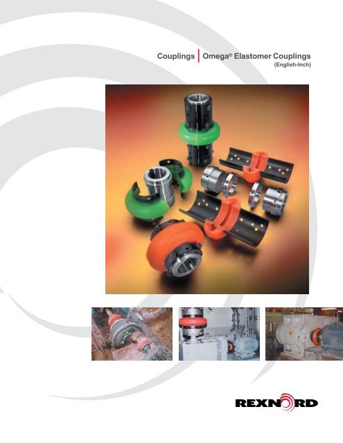
Couplings<strong>Omega</strong> ® Elastomer Couplings(English-Inch)
<strong>Omega</strong> ® Elastomeric CouplingsOEM Performance and CoverageThe unique split-in-half flex element and reversible hubssignificantly reduce total costs by reducing inventory andassembly time.<strong>Rex</strong>nord <strong>Omega</strong> couplings are non-lubricated, material-flexingcouplings utilizing a specially formulated polyurethane materialengineered for maximum durabilty, strength and fatigueresistance.The <strong>Rex</strong> <strong>Omega</strong> HSU coupling (green) is specifically designedfor hot and humid conditions.<strong>Rex</strong>nord is the leading coupling provider in the industry with afull-line of available solutions supported by trained customerservice and application engineering professionals focused onlyon our coupling product line. For more information, contactyour local <strong>Rex</strong>nord account executive.Features and Benefits• Split-in-half flex elementdesign for simplifiedassembly and disassembly• Our selection softwaremakes choosing theright coupling a snapTorsionally SoftFlex ElementRadial BoltingSplit-in-Half Design• Interchangeable hubs allowfor reduced inventory• High misalignment capacityaccommodates unavoidablemisalignment with lowreactionary forces• Torsionally soft flexelement cushions shockloads and vibrationextending equipment life• Polyurethane flex elementdoes not require lubrication• <strong>Rex</strong>nord field specialists arelocally based experts availableto support key end-users• The <strong>Rex</strong>nord <strong>Omega</strong>HSU coupling (green) isspecifically designed for hotand humid environments.In addition, the HSU materialperforms well in causticand acidic environments.Consult <strong>Rex</strong>nord engineeringfor your application.Polyurethane-to-Metal BondInterchangeable Hubs• Polyurethane-to-metalbond eliminates assemblyand slippage problemsassociated with mechanicallyclamped designsTable Of ContentsDESCRIPTIONPAGEInstallation and Misalignment Ratings 3Standard Close Coupled Design 4 – 5Spacer Design 6 – 7Spacing Options and Extended Spacer Design 8 – 9Mill Motor Design 10Special Designs 11Selection 12–14Bore Specifications and Finished Stock Bore Hubs 15<strong>Rex</strong>nord <strong>Omega</strong> couplings operate ineither horizontal or vertical applicationswithout any additional components.Ease of installation, ease ofmaintenance, and visual inspectionmake these couplings a must formany applications such as this mashcooker in a brewery.Never operatecoupling without an OSHA approved guard.Ordering 162
InstallationMount one hub to shaft, leave otherhub loose for adjustment of spacing.Place half of the <strong>Rex</strong>nord ® <strong>Omega</strong> ®element around hubs and secure withself-locking capscrews. <strong>Omega</strong>element will space the other hub.Now secure the other hub.Mount other half of the <strong>Omega</strong>element. Tighten all capscrews torecommended torques below andyou’re done! Refer to the installationinstruction for further details.Severe static testing (5 × rating)shows element flexibility, ruggeddesign and positive adhesivebond to the metal shoes.Angular4°3°2°1°0°Size 2-10<strong>Omega</strong> ® CouplingAllowable MisalignmentSize 20-50OMEGAHUBSize 60-80Tested ToughRigorous testing demonstrates thatthe <strong>Rex</strong>nord <strong>Omega</strong> coupling protectsconnected equipment from the damagingeffects of misalignment, vibration andgross overload. Where other couplingdesigns might allow equipmentdamage, the super flexible element of<strong>Rex</strong>nord <strong>Omega</strong> couplings minimizesthe reactionary forces on equipmentbearings under severe misalignmentconditions and reduces the effectsof excessive shock overloads.ParallelOMEGAHUBOMEGAHUBSize 100-140AngularOMEGAHUB1/32 1/16 3/32 1/8 3/16ParallelNote:Any combination of parallel and angular misalignment which falls under the trianglewill not cause a premature fatigue failure of the flexible element in normal use.Demonstrates coupling’s ability toaccept severe misalignment.- Important-Recommended Capscrew TourqueFor Proper InstallationCoupling Torque - DrySize In. Lbs. Ft. Lbs.234 204 17510203040360 30506070 900 75801001203240 270140 7080 590NOTE: Capscrews have self locking patches whichshould not be reused more than twice. Capscrews canbe further used if a thread locking adhesive is applied.Do NOT Lubricate Capscrew ThreadsImportant Note:Coupling alignment is directly related tosmooth, efficient equipment operation. Careshould be taken for best possible alignment.3
With Straight Bore HubsBC BB CBNote: Hub/shoulder designvaries per couplingsize. Consult <strong>Rex</strong>nordfor specific sizeassembly drawings.D(OUT) (OUT) (IN) (IN)AF(HUBS OUTBOARD)F(HUBS INBOARD)Recom.Dimensions In Inches<strong>Omega</strong>Continuous ContinuousMax.Max.WeightCouplingHP/100 TorqueCFBoreRPM A BD(Lb.)SizeRPM (In. Lbs.)(In.) (In.) (Out) (In.) (Out)E2 1.13 0.30 190 7500 3.5 0.94 1.34 1.90 1.85 3.22 3.78 1.2E3 1.38 0.58 365 7500 4.00 1.50 0.81 1.31 2.32 3.81 4.31 2.4E4 1.63 0.88 550 7500 4.56 1.69 0.44 1.31 2.60 3.81 4.69 3.0E5 1.88 1.48 925 7500 5.38 1.75 0.81 1.81 3.13 4.31 5.31 5.4E10 2.13 2.30 1450 7500 6.38 1.88 0.56 1.81 3.65 4.31 5.56 8.2E20 2.38 3.65 2300 6600 7.25 2.06 0.50 2.38 4.48 4.62 6.50 13.0E30 2.88 5.79 3650 5800 8.25 2.31 0.56 2.44 5.42 5.19 7.06 21E40 3.38 8.85 5500 5000 9.50 2.50 0.56 2.68 6.63 5.56 7.68 35E50 3.63 12.14 7650 4200 11.00 2.75 0.63 3.38 8.13 6.13 8.88 54E60 4 19.84 12,500 3800 12.50 3.25 0.69 3.44 8.75 7.19 9.94 72E70 4.5 35.12 22,125 3600 14.00 3.62 0.75 3.75 9.25 8.00 11.00 86E80 6 62.7 39,500 2000 16.00 4.87 0.75 5.00 11.25 10.50 14.75 170E100 6.75 135 85,050 1900 21.00 5.50 1.75 3.75 14.13 12.75 14.75 244E120 7.5 270 170,100 1800 25.00 6.00 2.25 4.88 17.63 14.24 16.88 425E140 11 540 340,200 1500 30.00 7.00 3.00 5.00 20.88 17.00 19.00 746 See page 14 for larger bore capacities with shallow keyways• Split-In-Half Flex ElementAllows disassembly and replacement withoutdisturbing hubs or connected equipment.• Reversible HubsAccommodates different shaft spacingrequirements, and allows compression bushingsto be installed from either side of the hub.Straight Bore Hubs QD Hubs and Bushings TAPER-LOCK ® Hubs and Bushings4Note: Dimensions subject to change. Certified dimensions of ordered material furnished on request.
With Compression Bushed HubsBFCBFCB(OUT)(IN)DA(OUT)(IN)DANOTE: Bushings are NOTQD TAPER LOCK ®included with hubs(E3-E80 Dwg. Only)S p ecificatio n D ata With Q D H u b sD imensio ns In In chesO megaRecom. C o n tin uous C ontin uousC o uplin g QD Max. B ore H P /100 To rq u e Max.CF Weig h tS iz e B ush. No. (In.) R P M (In . Lbs.) R P M A B ( In.) ( O u t)D ( In. ) (O u t)(L b .)E 4 JA1.19. 8855075004.561.001.221.882.603.223.882. 1E 5 S H 1.631.4892575005.381.251.751.883.134.254.503. 6E 10 S D S 1.942.30145075006.381.311.192.313.653.814.944. 8E 20 S K 2.503.65230066007.251.880.622.624.484.256.388. 5E 30 S F 2.945.79365058008.252.001.442.195.425.446.1914. 0E 40 E 3.508.85550050009.502.631.251.756.636.507.0023. 8E 50 E 3.5012.147650420011.002.631.372.888.136.638.1337. 6E 60 F 3.9419.8412,500380012.503.631.501.898.758.759.1345. 5E 70 J 4.5035.1222,125360014.004.501.311.439.2513.3110.4368. 1E 80 M 5.5062.7039,500200016.006.750.751.2511.2514.2514.75140E 100 M 5.5013585,050190021.006.801.751.1614.1315.3414.75250E 120 N 6.00270150,000180025.008.121.741.1617.6317.9616.88475E 140 P 7.00540250,000150030.009.360.303.0020.8819.0021.78782NO TE : D imensions may vary depending on bushing manufacturer.S p ecificatio n D ata With TA P E R -L O C K®H u b sO megaRecom. C o n tin uous C ontin uousD imensio ns In In chesC o uplin gS iz eTLB ush. No.Max. B ore(In.)H P /100R P MTo rq u e(In . Lbs.)Max.R P M A B C D FWeig h t(L b .)E 3 10081.00. 5836575004.00. 881.682.323.441. 8E 4 10081.00. 8855075004.56. 881.682.603.442. 6E 5 11081.131.4892575005.38. 882.193.133.944. 0E 10 13101.44*2.30145075006.381.002.063.654.066. 0E 20 16101.69*3.65230066007.251.002.504.484.509. 0E 30 20122.12*5.79365058008.251.252.565.425.0613. 6E 40 25172.69*8.85550050009.501.752.386.635.8821. 8E 50 25172.69*12.147650420011.001.753.008.136.5031. 5E 60 30203.25*19.8412,500380012.502.003.318.757.3146. 6E 70 35353.9435.1222,125360014.003.502.389.259.3866. 7E 80 40404.4462.7039,500200016.004.003.7511.2511.7582( In.) ( O u t)( In. ) (O u t)E 100 45454.9413585,050190021.004.501.506.0014.1310.5015.00250E 120 50505.00270126,000180025.005.002.007.1317.6312.0017.13408E 140 70607.00540340,200150030.006.003.007.0020.8815.0019.00660With shallow keyway.Service factor = 1.0. This rating may be lower is limited by the bushing rating, particularly if severe service conditions exist. C onsult bushing manufacturer.Without compression bushings.Inboard hub mounting (see drawing on page 4) requires bushing installation from coupling ends. A llow space (extra “B ” dimension) betweencoupling ends and equipment for bushing assembly/disassembly. Reverse taper hubs are available; consult <strong>Rex</strong>nord.A size 8065 bushing hub with 8.00" max bore is also available. C onsult <strong>Rex</strong>nord.Maximum bushing rating.*With steel bushingsNote: Dimensions subject to change. Certified dimensions of ordered material furnished on request. 5
With Straight Bore HubsBFCNote: Hub/shoulder designvaries per couplingsize. Consult <strong>Rex</strong>nordfor specific sizeassembly drawings.DAS p ecificatio n D ata With S traig h t B o re H u b sD imensio n s In In chesO mega Recom. C o n tinuous C o n tinuousC o u p lin g Max. B ore H P /100 To rq u e Max.CF W eightS iz e (In.) R P M (In . L b s.) R P M A B ( In .) ( O u t)D ( In .)(O u t)(L b. )E S 2-R 1.13. 3019075003.50. 943.504.001.855.755.922. 3E S 3-R 1.38. 5836575004.001.503.505.002.327.258.004. 0E S 4-R 1.63. 8855075004.561.693.505.002.607.258.385. 1E S 5-R 1.881.4892575005.381.753.505.003.137.258.507. 5E S 10-R 2.132.30145075006.381.883.505.003.657.258.7510. 3E S 20 2.383.65230048007.252.062.557.004.489.3811.1215. 6E S 30 2.885.79365042008.252.312.057.005.429.3811.6225. 1E S 40 3.388.85550036009.502.501.677.006.639.3812.0040E S 50 3.6312.147650310011.002.751.177.008.139.3812.5060E S 60 4.0019.8412,500280012.503.252.679.758.7512.5016.2584E S 70 4.5035.1222,125260014.003.621.999.759.2512.5017.00102E S 80 6.0062.7039,500180016.004.872.189.7511.2512.5019.50180Suffix “R” designates high speed ring design. Rings are furnished standard for sizes E S2-R to E S10-R, optional for sizes E S20 to E S80.Service factor = 1.0.Spacer coupling furnished with optional high speed rings (sizes E S 20 to E S 80) can be operated up to maximum allowable speeds for standardseries couplings. S ee RP M Ratings on page 4.Minimum shaft spacing is 0.25 inch. S ee page 8 for additional information.O verall length of element.With max bore hubs. See page 14 for larger bore capacities with shallow keyways.• Adjustable Spacer DesignOptional hole mounting positions and reversiblehub features allow adjustment to accommodatemost shaft spacing requirements (see page 8)• Universal HubsStraight bore and compression bushed hubdesigns are identical and interchangeable for boththe spacer and standard couplings. This meansmaximum utilization of off the shelf inventory.Straight Bore Hubs QD Hubs and Bushings TAPER-LOCK ® Hubs and Bushings6Note: Dimensions subject to change. Certified dimensions of ordered material furnished on request.
“Adjustability”Shaft Spacing Possibilities(Using Straight Bore Hubs)The <strong>Rex</strong>nord ® <strong>Omega</strong> ® spacer coupling design (pages 6-7) provides clear space between hubs. There are no interfering centermembers or spools which allows shaft spacing as small as 1 /4”; however, for such small spacings, use of the standard <strong>Omega</strong> couplingwould be recommended. The maximum shaft spacing for each coupling is shown of pages 6-7. Any ANSI, ISO or DIN spacing between1/4 inch and the maximum listed can be achieved without any additional parts. Hubs can be placed on the shafts as shown below.(OUT) (OUT) (OUT) (IN)Figure ABoth hubs mounted outboardFigure BOne hub mounted inboardOne hub mounted outboard(IN)(IN)Figure CBoth hubs mounted inwardUse one half of the flex element to establish shaft spacing and appropriate mounting position. Optional hole mounting positionsand reversible hubs allow adjustments as needed. Select the combination which most closely matches the dimensionsdesired between shafts (Figure D). Drawings with specific mounting positions/dimensions are available from <strong>Rex</strong>nord.Figure DNote: Optional capscrew hole mounting positionsallow easy on-site adjustment to meetvarious shaft spacing requirements.Hubs can be flush with the shaft end (not shown), extended beyond the end of the shaft (Figure E) or recessedbehind the shaft end provided there is sufficient keyway engagement (Figure F). Special sleeve extensions(see page 9) are available for spacing requirements in excess of those listed on pages 6-7.8Note: Shaft engagement should be equal to orgreater than .8 times shaft diameter.100% shaft engagement is suggested forcompression bushed hubs.Figure EFigure F
Special Designs<strong>Rex</strong>nord ® <strong>Omega</strong> ® HSU ElementHydrolytically Stable Urethane for superior resistance to hot andhumid conditions in addition to acidic and alkaline environments.The <strong>Omega</strong> HSU element in interchangeable with existing hubs.StainlessSteel<strong>Rex</strong>nord ® <strong>Omega</strong> ® Positive DriveCouplingWith interlocking drive fail safe requirements.<strong>Rex</strong>nord ® <strong>Omega</strong> ® Stainless SteelElementCorrosion resistant 303/304 stainless steel shoes for severeenvironments.Stainless steel hubs also available.<strong>Rex</strong>nord ® <strong>Omega</strong> ® Keyless Hub/Bushing DesignSeveral optional keyless Hub/Bushing designs are availablefor increased bore end shaft gap requirements.<strong>Rex</strong>nord ® <strong>Omega</strong> ® Spline Bore Hub1. Number of Teeth – Ex. 14T2. Pitch Fraction – Ex. 12/24 Pitch3. Pressure Angle – 30° P.A.4. Type of Tooth Shape – Ex. Involute or Straight Side5. Type of Root – Ex. Fillet or Flat Root6. Tolerance – Ex. Class I thru VII7. Type of Fit – Ex. Side Fit or Major Diameter Fit<strong>Rex</strong>nord ® <strong>Omega</strong> ® Light Duty ElementAvailable in size E2LD only. Minimum O.D. (2.5”) for lowprofile applications. Max torque rating of 100 In. Lbs.Note: Dimensions subject to change. Certified dimensions of ordered material furnished on request. 11
Selection Procedures1. Determine HP/100RPM: HP/100 RPM = Horsepower x 100RPM2. Determine Service Factor:Select the proper Service Factor from Table on page13. If not listed, see Load Classification Table.Remember to consider both driver and drivenequipment and temperature requirements.3. Multiply HP/100 by the service factor to get equivalent HP/100 RPM.4. Select the Coupling Size:From Table 1, with a rating equal to or greater than theequivalent HP/100 RPM determined in Step 3.5. Check Limiting Conditions:Be sure that the operating speed of the coupling doesnot exceed maximum RPM listed on page 4-7.6. Select Desired Hub Type:Select desired hub type and check maximumallowable coupling bore on page 14.OR1. Determine Operating Torque:( 63,000 x HP RPM )2. Multiply by Service FactorSelect the proper Service Factor from Table on page 13.3. Select the Coupling Size:Select coupling size from Table 2 with a capacityequal to or greater than determined in Step 2.4. Follow Steps 5 & 6 AboveTable 1SizeEquivalentStandard Spacer HP/100 RPME2 ES2 0.3E3 ES3 0.58E4 ES4 0.88E5 ES5 1.48E10 ES10 2.3E20 ES20 3.65E30 ES30 5.79E40 ES40 8.85E50 ES50 12.14E60 ES60 19.84E70 ES70 35.12E80 ES80 62.7E100 NA 135E120 NA 270E140 NA 540Table 2Torque CapacitySizeContinuousTorque(In. Lbs.)SizeContinuousTorque(In. Lbs.)2 190 40 5,5003 365 50 7,6504 550 60 12,5005 925 70 22,12510 1,450 80 39,50020 2,300 100 85,05030 3,650 120 170,100140 340,200Service FactorsService Factors are a means of classifying different equipment and applications into various load classifications.Due to variations in application of equipment, service factors are used to adjust equipment ratings to accommodatefor variable loading conditions. This is a general guide. More specific factors are given on page 13.Load ClassificationsService FactorsContinuous service and running loads vary only slightly. 1.0Torque loading varies during operation of the equipment. 1.5Torque loading varies during operation, frequent stop/2.0start cycles are encountered.<strong>Omega</strong> ® ElementTemperature Range (Ambient)-40°F+200°Fto-40°C+93°CHigh TemperatureService Factor Adjustment*Ambient Temp. S.F. Adjust.+150°F (66°C) 0.025+165°F (74°C) 0.05+180°F (82°C) 0.75+200°F (93°C) 1*Added to application service factorFor shock loading and substantial torque variations. 2.5For heavy shock loading or light reversing drives. 3.0Reversing torque loads do not necessarily mean reversalof rotation. Depending upon severity of torque reversal,Consult <strong>Rex</strong>nordsuch loads must be classified between “medium” and“extreme.”The service factor adjustmentfor high temperature is inaddition to the service factorconsideration for the driver anddriven equipment. However, ifhigh temperatures are typical fora specific application, maximumtemperature consideration isincorporated into the “typical”service factor listing on page 13.i.e., steel mill runout tables.12
13Typical Service Factors – Motor And Turbine Driven Equipment AGITATORSVertical and Horizontal Screw Propeller, Paddle . . . . . . . . . . . . . . . . . . . . . . . 1.5BLOWERSCentrifugal . . . . . . . . . . . . . . . . . . . . . . . . . . . . . . . . . . . . . . . . . . . . . . . . . . . . 1.0Lobe or Vane . . . . . . . . . . . . . . . . . . . . . . . . . . . . . . . . . . . . . . . . . . . . . . . . . . 1.5CAR DUMPER AND PULLER. . . . . . . . . . . . . . . . . . . . . . . . . . . . . . . . . . . . . . . 2.0COMPRESSORSCentrifugal . . . . . . . . . . . . . . . . . . . . . . . . . . . . . . . . . . . . . . . . . . . . . . . . . . . . 1.0Rotary, Lobe, or Vane . . . . . . . . . . . . . . . . . . . . . . . . . . . . . . . . . . . . . . . . . . . 2.0Rotary, Screw. . . . . . . . . . . . . . . . . . . . . . . . . . . . . . . . . . . . . . . . . . . . . . . . . 1.25Reciprocating . . . . . . . . . . . . . . . . . . . . . . . . . . . . . . . . . . . . . . . . . . . . . . . . . . . ÁCONVEYORSApron, Assembly, Belt, Chain, Flight, Oven . . . . . . . . . . . . . . . . . . . . . . . . . . . 1.5Reciprocating . . . . . . . . . . . . . . . . . . . . . . . . . . . . . . . . . . . . . . . . . . . . . . . . . . . Screw . . . . . . . . . . . . . . . . . . . . . . . . . . . . . . . . . . . . . . . . . . . . . . . . . . . . . . . 1.25CRANES AND HOISTSMain Hoist – Medium Duty . . . . . . . . . . . . . . . . . . . . . . . . . . . . . . . . . . . . . . . . 2.0Main Hoist – Heavy Duty . . . . . . . . . . . . . . . . . . . . . . . . . . . . . . . . . . . . . . . . . 2.5Skip Hoist . . . . . . . . . . . . . . . . . . . . . . . . . . . . . . . . . . . . . . . . . . . . . . . . . . . . . 2.0Bridge, Travel or Trolley . . . . . . . . . . . . . . . . . . . . . . . . . . . . . . . . . . . . . . . . . . 2.0DREDGESCable Reel, Conveyor . . . . . . . . . . . . . . . . . . . . . . . . . . . . . . . . . . . . . . . . . . . 2.0Cutter Head Drive, Jig Drive . . . . . . . . . . . . . . . . . . . . . . . . . . . . . . . . . . . . . . . 3.0Pump, Screen, Drive, Stacker, Utility Winch. . . . . . . . . . . . . . . . . . . . . . . . . . . 2.0DYNAMOMETER . . . . . . . . . . . . . . . . . . . . . . . . . . . . . . . . . . . . . . . . . . . . . . . . 1.0ELEVATORSBucket, Freight . . . . . . . . . . . . . . . . . . . . . . . . . . . . . . . . . . . . . . . . . . . . . . . . . 2.5EXCITER, GENERATOR . . . . . . . . . . . . . . . . . . . . . . . . . . . . . . . . . . . . . . . . . . 1.0EXTRUDER, PLASTIC . . . . . . . . . . . . . . . . . . . . . . . . . . . . . . . . . . . . . . . . . . . . 2.0FANSCentrifugal . . . . . . . . . . . . . . . . . . . . . . . . . . . . . . . . . . . . . . . . . . . . . . . . . . . . 1.0Cooling Tower . . . . . . . . . . . . . . . . . . . . . . . . . . . . . . . . . . . . . . . . . . . . . . . . . 2.0Forced Draft and Induced Draft . . . . . . . . . . . . . . . . . . . . . . . . . . . . . . . . . . . . 1.5Large Mine . . . . . . . . . . . . . . . . . . . . . . . . . . . . . . . . . . . . . . . . . . . . . . . . . . . . 2.0Propeller . . . . . . . . . . . . . . . . . . . . . . . . . . . . . . . . . . . . . . . . . . . . . . . . . . . . . . 1.5GENERATORSEven Load . . . . . . . . . . . . . . . . . . . . . . . . . . . . . . . . . . . . . . . . . . . . . . . . . . . . 1.0Hoist or Railway Service. . . . . . . . . . . . . . . . . . . . . . . . . . . . . . . . . . . . . . . . . . 2.0Welder Load . . . . . . . . . . . . . . . . . . . . . . . . . . . . . . . . . . . . . . . . . . . . . . . . . . . 2.5PRINTING PRESS. . . . . . . . . . . . . . . . . . . . . . . . . . . . . . . . . . . . . . . . . . . . . . . . 2.0PUMPSCentrifugal . . . . . . . . . . . . . . . . . . . . . . . . . . . . . . . . . . . . . . . . . . . . . . . . . . . . 1.0Positive Displacement . . . . . . . . . . . . . . . . . . . . . . . . . . . . . . . . . . . . . . . . . . . 1.5Rotary – Gear, Lobe, Vane. . . . . . . . . . . . . . . . . . . . . . . . . . . . . . . . . . . . . . . . 1.5Reciprocating . . . . . . . . . . . . . . . . . . . . . . . . . . . . . . . . . . . . . . . . . . . . . . . . . . . Progressive Cavity . . . . . . . . . . . . . . . . . . . . . . . . . . . . . . . . . . . . . . . . . . . . . 1.25Peristaltic . . . . . . . . . . . . . . . . . . . . . . . . . . . . . . . . . . . . . . . . . . . . . . . . . . . . . 1.5SCREENSAir Washing . . . . . . . . . . . . . . . . . . . . . . . . . . . . . . . . . . . . . . . . . . . . . . . . . . . 3.0Grizzly. . . . . . . . . . . . . . . . . . . . . . . . . . . . . . . . . . . . . . . . . . . . . . . . . . . . . . . . 1.0Coal and Sand (Rotary) . . . . . . . . . . . . . . . . . . . . . . . . . . . . . . . . . . . . . . . . . . 2.0Vibrating . . . . . . . . . . . . . . . . . . . . . . . . . . . . . . . . . . . . . . . . . . . . . . . . . . . . . . 5.0SEWAGE DISPOSAL EQUIPMENT . . . . . . . . . . . . . . . . . . . . . . . . . . . . . . . . . . 1.5STOKER . . . . . . . . . . . . . . . . . . . . . . . . . . . . . . . . . . . . . . . . . . . . . . . . . . . . . . . 1.5AGGREGATE PROCESSING, CEMENTConcrete Mixers . . . . . . . . . . . . . . . . . . . . . . . . . . . . . . . . . . . . . . . . . . . . . . . . 2.0Crushers, Ore or Stone. . . . . . . . . . . . . . . . . . . . . . . . . . . . . . . . . . . . . . . . . . . 3.0Dryer, Rotary . . . . . . . . . . . . . . . . . . . . . . . . . . . . . . . . . . . . . . . . . . . . . . . . . . 2.0Grizzly. . . . . . . . . . . . . . . . . . . . . . . . . . . . . . . . . . . . . . . . . . . . . . . . . . . . . . . . 3.0Hammermill . . . . . . . . . . . . . . . . . . . . . . . . . . . . . . . . . . . . . . . . . . . . . . . . . . . 2.5Mining Kilns . . . . . . . . . . . . . . . . . . . . . . . . . . . . . . . . . . . . . . . . . . . . . . . . . . . 2.5Tube, Rod and Ball Mills . . . . . . . . . . . . . . . . . . . . . . . . . . . . . . . . . . . . . . . . . . 2.5Tumbling Mill or Barrel . . . . . . . . . . . . . . . . . . . . . . . . . . . . . . . . . . . . . . . . . . . 2.0BREWERY AND DISTILLINGBottling and Can Filling Machinery, Brew Kettle, Cooker, Mash Tub . . . . . . . . 1.0Scale Hopper (frequent peaks). . . . . . . . . . . . . . . . . . . . . . . . . . . . . . . . . . . . . 2.0FOOD INDUSTRYBottle and Can Filling . . . . . . . . . . . . . . . . . . . . . . . . . . . . . . . . . . . . . . . . . . . . 1.0Cereal Cooker . . . . . . . . . . . . . . . . . . . . . . . . . . . . . . . . . . . . . . . . . . . . . . . . . 1.0Dough Mixer, Meat Grinder . . . . . . . . . . . . . . . . . . . . . . . . . . . . . . . . . . . . . . . 2.0LUMBER INDUSTRYBand Resaw, Circular Resaw. . . . . . . . . . . . . . . . . . . . . . . . . . . . . . . . . . . . . . 2.0Edger, Head Rig, Hog, Log Haul. . . . . . . . . . . . . . . . . . . . . . . . . . . . . . . . . . . . 2.5Planer . . . . . . . . . . . . . . . . . . . . . . . . . . . . . . . . . . . . . . . . . . . . . . . . . . . . . . . . 2.0Rolls, Non-Reversing . . . . . . . . . . . . . . . . . . . . . . . . . . . . . . . . . . . . . . . . . . . . 2.0Rolls, Reversing . . . . . . . . . . . . . . . . . . . . . . . . . . . . . . . . . . . . . . . . . . . . . . . . 2.5Sawdust Conveyor . . . . . . . . . . . . . . . . . . . . . . . . . . . . . . . . . . . . . . . . . . . . . . 1.5Slab Conveyor, Sorting Table. . . . . . . . . . . . . . . . . . . . . . . . . . . . . . . . . . . . . . 2.0OIL INDUSTRYChiller . . . . . . . . . . . . . . . . . . . . . . . . . . . . . . . . . . . . . . . . . . . . . . . . . . . . . . . . 1.0POWER INDUSTRYAsh Handling Conveyors . . . . . . . . . . . . . . . . . . . . . . . . . . . . . . . . . . . . . . . . . 1.5Baghouse Air Handling Fans . . . . . . . . . . . . . . . . . . . . . . . . . . . . . . . . . . . . . . 1.5Ball Mill . . . . . . . . . . . . . . . . . . . . . . . . . . . . . . . . . . . . . . . . . . . . . . . . . . . . . . . 2.5Belt Conveyors . . . . . . . . . . . . . . . . . . . . . . . . . . . . . . . . . . . . . . . . . . . . . . . . . 1.5Circulating pumps (centrifugal). . . . . . . . . . . . . . . . . . . . . . . . . . . . . . . . . . . . . 1.0Coal Grinders and Crushers. . . . . . . . . . . . . . . . . . . . . . . . . . . . . . . . . . . . . . . 2.5Coal Pulverizers and Hammermills . . . . . . . . . . . . . . . . . . . . . . . . . . . . . . . . . 2.5Cooling Tower Fans . . . . . . . . . . . . . . . . . . . . . . . . . . . . . . . . . . . . . . . . . . . . . 2.0FGD Slurry Pumps (centrifugal) . . . . . . . . . . . . . . . . . . . . . . . . . . . . . . . . . . . . 1.0Forced Draft Fan and Induced Draft Fan . . . . . . . . . . . . . . . . . . . . . . . . . . . . . 1.5Primary Air, Recycling Fans . . . . . . . . . . . . . . . . . . . . . . . . . . . . . . . . . . . . . . . 1.5Traveling Water Screens . . . . . . . . . . . . . . . . . . . . . . . . . . . . . . . . . . . . . . . . . 1.0PULP & PAPER MILLSAgitator . . . . . . . . . . . . . . . . . . . . . . . . . . . . . . . . . . . . . . . . . . . . . . . . . . . . . . . 1.5Barking Drum . . . . . . . . . . . . . . . . . . . . . . . . . . . . . . . . . . . . . . . . . . . . . . . . . . 3.0Beater and Pulper. . . . . . . . . . . . . . . . . . . . . . . . . . . . . . . . . . . . . . . . . . . . . . . 2.0Bleacher . . . . . . . . . . . . . . . . . . . . . . . . . . . . . . . . . . . . . . . . . . . . . . . . . . . . . . 1.0Calendar. . . . . . . . . . . . . . . . . . . . . . . . . . . . . . . . . . . . . . . . . . . . . . . . . . . . . . 2.5Chipper. . . . . . . . . . . . . . . . . . . . . . . . . . . . . . . . . . . . . . . . . . . . . . . . . . . . . . . 3.5Couch, Cylinder Dryer . . . . . . . . . . . . . . . . . . . . . . . . . . . . . . . . . . . . . . . . . . . 2.0Felt Stretcher . . . . . . . . . . . . . . . . . . . . . . . . . . . . . . . . . . . . . . . . . . . . . . . . . . 1.0Fourdrinier . . . . . . . . . . . . . . . . . . . . . . . . . . . . . . . . . . . . . . . . . . . . . . . . . . . . 2.0Jordan. . . . . . . . . . . . . . . . . . . . . . . . . . . . . . . . . . . . . . . . . . . . . . . . . . . . . . . . 2.5Press . . . . . . . . . . . . . . . . . . . . . . . . . . . . . . . . . . . . . . . . . . . . . . . . . . . . . . . . 2.5Pulp Grinder . . . . . . . . . . . . . . . . . . . . . . . . . . . . . . . . . . . . . . . . . . . . . . . . . . . 2.5Stock Chests . . . . . . . . . . . . . . . . . . . . . . . . . . . . . . . . . . . . . . . . . . . . . . . . . . 1.5Stock PumpCentrifugal . . . . . . . . . . . . . . . . . . . . . . . . . . . . . . . . . . . . . . . . . . . . . . . . . . . 1.0Reciprocating . . . . . . . . . . . . . . . . . . . . . . . . . . . . . . . . . . . . . . . . . . . . . . . . . 2.5Rotary. . . . . . . . . . . . . . . . . . . . . . . . . . . . . . . . . . . . . . . . . . . . . . . . . . . . . . . 2.0Suction Roll. . . . . . . . . . . . . . . . . . . . . . . . . . . . . . . . . . . . . . . . . . . . . . . . . . . . 2.5Winder . . . . . . . . . . . . . . . . . . . . . . . . . . . . . . . . . . . . . . . . . . . . . . . . . . . . . . . 2.0RUBBER INDUSTRYBanbury Mixer . . . . . . . . . . . . . . . . . . . . . . . . . . . . . . . . . . . . . . . . . . . . . . . . . 3.0Calendar. . . . . . . . . . . . . . . . . . . . . . . . . . . . . . . . . . . . . . . . . . . . . . . . . . . . . . 2.5Cracker, Mix Mill, Plasticator, Refiner, Sheeter, Tire Building Machine . . . . . . 2.0Tire and Tube Press Opener . . . . . . . . . . . . . . . . . . . . . . . . . . . . . . . . . . . . . . 1.0Tiber and Strainer. . . . . . . . . . . . . . . . . . . . . . . . . . . . . . . . . . . . . . . . . . . . . . . 2.0Warming Mill. . . . . . . . . . . . . . . . . . . . . . . . . . . . . . . . . . . . . . . . . . . . . . . . . . . 2.5Washer . . . . . . . . . . . . . . . . . . . . . . . . . . . . . . . . . . . . . . . . . . . . . . . . . . . . . . . 3.0STEEL INDUSTRYCoilers . . . . . . . . . . . . . . . . . . . . . . . . . . . . . . . . . . . . . . . . . . . . . . . . . . . . . . . 2.0Draw Benches . . . . . . . . . . . . . . . . . . . . . . . . . . . . . . . . . . . . . . . . . . . . . . . . . 2.0Edger Drives. . . . . . . . . . . . . . . . . . . . . . . . . . . . . . . . . . . . . . . . . . . . . . . . . . . 2.0Reel Drives . . . . . . . . . . . . . . . . . . . . . . . . . . . . . . . . . . . . . . . . . . . . . . . . . . . . 2.0Runout Tables (Non-Reversing). . . . . . . . . . . . . . . . . . . . . . . . . . . . . . . . . . . . 3.0Runout Tables (Reversing). . . . . . . . . . . . . . . . . . . . . . . . . . . . . . . . . . . . . . . . 4.5Soaking Pit Cover Drives . . . . . . . . . . . . . . . . . . . . . . . . . . . . . . . . . . . . . . . . . 3.0Tube Conveyor Rolls . . . . . . . . . . . . . . . . . . . . . . . . . . . . . . . . . . . . . . . . . . . . 2.5Wire Drawing . . . . . . . . . . . . . . . . . . . . . . . . . . . . . . . . . . . . . . . . . . . . . . . . . . 2.0TEXTILE MILLSBatcher, Calender, Card Machine, Dry Can . . . . . . . . . . . . . . . . . . . . . . . . . . . 2.0Dyeing Machinery. . . . . . . . . . . . . . . . . . . . . . . . . . . . . . . . . . . . . . . . . . . . . . . 1.0Loom. . . . . . . . . . . . . . . . . . . . . . . . . . . . . . . . . . . . . . . . . . . . . . . . . . . . . . . . . 2.0Mangle, Napper, Soaper . . . . . . . . . . . . . . . . . . . . . . . . . . . . . . . . . . . . . . . . . 1.5Spinner, Tenter Frame . . . . . . . . . . . . . . . . . . . . . . . . . . . . . . . . . . . . . . . . . . . 2.0TypicalGeneral ApplicationService FactorTypicalIndustry Application (cont’d)Service FactorThe Service Factors listed are intended only as a general guide and for smoothpower sources such as electric motors. For reciprocating prime movers, such asdiesel or gas engines, add the following service factor:For 8 or more cylinders, add 0.5For 6 cylinders, add 1.0For 4 cylinders, add 1.5For less than 4 cylinders, consult <strong>Rex</strong>nordIf both driver and driven equipment are reciprocating, consult <strong>Rex</strong>nord.Add 0.5 to service factor if drive is a hydraulic motor.<strong>Omega</strong> couplings are not recommended for turbine drives if the coupling cannot beprotected from steam leakage or from speeds in excess of the coupling’s publishedspeed rating (pages 4-7). Consult <strong>Rex</strong>nord EngineeringIMPORTANT NOTE – The coupling selection criteria is intended for thedetermination of the coupling and style only. It is also recommended that the systembe analyzed for torsional and lateral stability using the specific coupling mass-elasticdata available from <strong>Rex</strong>nord. This analysis is the responsibility of the user since thecoupling is only a single component in the system.CAUTION – In the drive systems sensitive to axial movement (i.e. sleeve bearingequipment), it may be necessary to limit axial force and/or displacement. Consult<strong>Rex</strong>nord for proper installation procedure.
Coupling SelectionB o re R angesStraightB oreT APE R-LOCK®Q DH u b S iz e Min . B o re Max. B o reB ushin gN u mb erMin imu mB o reMaximu mB o reB u shin gN u mb erMinimu mB o reMaximu mB o re2 NoMin.1 3 / 16NANA3 3/8 1 3 /8 10081/2 1 NA4 3/8 1 3 /4 10081/2 1 JA3/8 1 3 /165 3 /8 1 / 1611081 /2 1 1 /8SH 1 /2 1 5 /8103 /8 2 1 /4 13101 /2 1 7 /16 S D S1 /21 15 /16203 /4 2 3 /4 16101 /2 1 11 /16 S K1 /2 2 1 /2303 /4 3 1 /4 20121 /2 2 1 /8SF 1 /2 2 / 16403 /4 3 3 /4 25171 /2 2 11 /16E 7 /8 3 1 /2501 1 /8 4 25171 /2 2 11 /16E7 /8 3 1 /2601 1 /8 4 1 /2 30201 5/ 163 1 /4F1 3 / 16701 3 /8 4 7 /8 35351 3 / 163 15 /16J 1 7 / 164 1 /2801 7 /8 6 3 /4 40401 7 / 164 7 /16M1 / 165 1 /21001 7 /8 7 1 /4 45451 / 164 15 /16 M 1 / 165 1 /21201 7 /8 8 1 /4 50502 5 / 166 N 2 7 / 1661401 7 /8 9 1 /4 70604 9 / 167 P 2 / 167Bushings are not included with bushed hubs. Bushing bore ranges may vary, check with bushing manufacturer.Rough bores are slightly undersized to conform with minimum bore specifications.With shallow keyway and steel hub<strong>Rex</strong>nord <strong>Omega</strong> ® Couplings Interchange D o d g e L o vejo y TB WoodsF alk G ridK o p -F lexO megaP ara-F lex (R u b ber) (Rubber) 1000T10TFG ear2 L-0955 1020T20T3 1H3 L-099,L-1006 1030T30T4 1H4 L-1107 1040T40T4 1H5 50L-1108 1040T,1050T40T,50T5,61H,1/2H1060L-150,L-1909 1050T,1060T50T,60T7,81 1 /2H2070L-225101060T,1070T60T,70T8,91 1 /2H,2H3080L-276111070T,1080T70T,80T9,102H,2/2H4090121090T90T102 1 /2H501101090T90T112 1 /2H60120131090T90T112 1 /2H70140141100T100T133H80160161110T110T143H100200NA1120T120T15120240NA1130T,1140T130T,140T16, 17140280NA1150T150T18C AUTION should be applied when using any interchange chart (particularly with respect to gear and grid couplings) since each product has differentdimensions, benefits and service factor recommendations. This interchange is based on typical specifications for centrifugal pump applications at 1750RPM. F or specific applications, consult <strong>Rex</strong>nord, refer to page 12 ,or ask for our free Slide Selector. Use this chart as a general guide.C onsult <strong>Rex</strong>nord.14
ShaftDia.Class 1Clearance FitInterferenceFitShaftDia.Class 1Clearance FitBore SpecificationCouplings will be bored in accordance with AGMA Standard 9002 for flexible couplings.Finished bore hubs will be Class 1 clearance fit unless otherwise specified.InterferenceFit1/2 .500-.501 .4990-.4995 2 3/8 2.3750-2.3765 2.373-2.3745/8 .625-.626 .6240-.6245 2 1/2 2.5000-2.5015 2.498-2.4993/4 .750-.751 .7490-.7495 2 5/8 2.6250-2.6265 2.623-2.6247/8 .875-.876 .8740-.8745 2 3/4 2.7500-2.7515 2.748-2.7491 1.000-1.001 .9990-.9995 2 7/8 2.8750-2.8765 2.873-2.8741 1/8 1.125-1.126 1.1240-1.1245 3 3.0000-3.0015 2.998-2.9991 1/4 1.250-1.251 1.2490-1.2495 3 1/4 3.2500-3.2515 3.2470-3.24851 3/8 1.375-1.376 1.3740-1.3745 3 1/2 3.5000-3.5015 3.4970-3.49851 1/2 1.500-1.501 1.4990-1.4995 3 5/8 3.6250-3.6265 3.6220-3.62351 5/8 1.625-1.626 1.623-1.624 3 3/4 3.7500-3.7515 3.7470-3.74851 3/4 1.750-1.751 1.748-1.749 4 4.0000-4.0015 3.9970-3.99851 7/8 1.875-1.876 1.873-1.874 4 1/2 4.500-4.502 4.4965-4.49802 2.000-2.001 1.998-1.999 5 5.000-5.002 4.9965-4.99802 1/8 2.1250-2.1265 2.123-2.124 5 1/2 5.500-5.502 5.4960-5.49752 1/4 2.2500-2.2515 2.248-2.249 6 6.000-6.002 5.9960-5.9975B o re S iz esN o min al K eyw ay S etscrewS h aftD ia. C lassD iameterD epthWid th2B N CO ver T h ruS q.R ect.Thread5 / 167 / 167/ 169/ 169/ 167/87 /8 1 1 /4Finished Stock Bore Hubs Available (listed by part number)(STRAIGHT BORE HUBS BORED IN ACCORDANCE WITH AGMA STANDARD 9002 CLASS 1 CLEARANCE FIT)RecommendedTightenin gTo rq u e(In . L b s.)Size Bore 2 HSB 3 HSB 4 HSB 5 HSB 10 HSB 20 HSB 30 HSB 40 HSB 50 HSB 60 HSB5/8 7300218 7300242 73002723/4 7300220 7300244 7300274 73003067/8 7300225 7300245 7300275 7300308 738582115/16 … … … 73003091 7300230 7300250 7300280 7300310 73858201-1/16 … … … 73003121-1/8 7300235 7300255 7300285 7300315 7300345 7300649 73858251-3/16 … … 7300286 73003181-1/4 … 7300260 7300290 7300320 7300350 7300651 73858221-5/16 … … … 73003221-3/8 … 7300265 7300295 7300325 7300355 7300963 73858231-7/16 … … 7300296 7300326 73003561-1/2 … … 7300298 7300328 7300358 7300652 7300661 73006691-5/8 … … 7300300 7300330 7300360 7300653 7369351 73693521-11/16 … … … 7300332 7300361 7300656 73009641-3/4 … … … 7300333 7300362 7300654 7300663 7300672 73006811-7/8 … … … 7300335 7300365 7300655 7300662 7300671 73006841-15/16 … … … … 7300366 73904102 … … … … 7300368 7390411 739041373904172-1/8 … … … … 7300370 7300657 7300664 7300673 7300961 73904182-3/16 … … … … … 73904122-1/4 … … … … … 7300658 7300665 7300674 73006822-3/8 … … … … … 7300659 7300666 7300675 7300962 73006912-1/2 … … … … … … 7300667 73006762-11/16 … … … … … … 7300965 73006782-3/4 … … … … … … 7390414 73904152-7/8 … … … … … … 7300668 7300677 7300683 73006923-5/16 … … … … … … … … … 73006933-3/8 … … … … … … … 7300679 7300686 73006943 / 321/83/ 161 /45/ 163 /81 /25 /83 /47 /83 / 64–1/ 163/ 643/ 321/ 161 /83 / 325/ 321/83 / 161 /81 /43 / 165 / 167 / 323 /81 /47 / 165 / 163 /85 /87 / 163 /41 /27 /83 /41/4-20871 1 /4 1 3 /83/8-162901 3 /8 1 3 /41 3 /4 2 1 /41 /2-136202 1 /4 2 3 /45 /8-1113252 3 /4 3 1 /43 /4-1024003 1 /4 3 3 /47 /8-952003 3 /4 4 1 /2 1 1 /24 1 /2 5 1 /2 1 1 /45 1 /2 6 1 /2 1 1 /21-872006 1 /2 7 1 /2 1 3 /47 1 /2 9 2 1 3/4Maximum setscrew diameter is 1/4-20UNC for size #2 hub.Maximum setscrew size for hub sizes #3 thru #10 is/8-16 UNC .15
Ordering InstructionsStandard and Spacer CouplingsWhen ordering a complete coupling, specify size/type of element and hubs (two hubs per complete coupling) options include:Element[E2 – E140] standard (close coupled)[ES2-R – ES80] spacerHub1. Drawing of HUB showing completebore and keyway details.— O R —2. Drawing of SHAFT with dimensions shown(LD) Large Diameter, Specify in Decimals.(S)(T)(P)[2HRB – 140HRB] straight hub-rough bore[2HSB – 60HSB] straight hub-stock bore (specify bore size from table on page 15)[2HCB – 140HCB] straight hub-custom bore (specify bore and keyway)[4HQD – 140HQD] hub-QD (bushing not included)[3HTL – 140HTL] hub-TAPER-LOCK ® (bushing not included)[10HMM – 140HMM] straight hub-mill motor (specify mill motor number, rough or custom bore)Order Example:Complete E50 standard (close coupled) coupling with one finished bore 2 1 /8” hub w/standard keyway and one QD hub less bushing.Order description:1 ea. E50 element1 ea. 50HSB – 2 1 /8” – std.1 ea. 50 HQD – steelWKEYWAYWNKEYWAY LD NWTKEYWAYNPLD NPE SETNLD NP TPE SEPPbelow, allowing E S<strong>Rex</strong>nord to bore hubs to suit. ELength of Taper, Measure parallel to Shaft centerline.Taper per Foot, Difference in Diameter in one foot length.Clearance space for drawing Hub up on tapered shaft.Usually 1 /8” or 1 /4”, depending on shaft size and taper.Keyway: Width, Depth.Note: Specify if keyway is parallel to Taper or if parallel to shaftcenter line.Specify depth at larger diameter of Taper ifkeyway is parallel to shaft center line.Tapered BoresWith connected equipment in fixed position, thefollowing additional information is necessary:Dimensions “V” and “X” must be given when one or bothconnected machines are fixed on their bases. Advise ifAVAILABLEdimension “X” is LENGTH fixed, OF or if variable between what limits.SHAFTAVAILABLELENGTH OFAVAILABLE SHAFTLENGTH OFCSHAFTVVXCCXV XA fixed “X” dimension may require altered or special couplingHUB hubs. COUNTERBORED Often the straight SHAFT bored PROJECTS hub can be HUB positioned SHORTENED on its shaftallowing the use of a standard coupling. See illustrations below.HUB COUNTERBORED SHAFT PROJECTS HUB SHORTENEDHUB COUNTERBOREDSHAFT PROJECTSConsult A.G.M.A. Standard 9002 “Taper Boresfor Flexible Couplings” for new applications.HUB SHORTENED16
World Class Customer ServiceFor more than 100 years, the dedicated people of <strong>Rex</strong>nordhave delivered excellence in quality and service to ourcustomers around the globe. <strong>Rex</strong>nord is a trustedname when it comes to providing skillfully engineeredproducts that improve productivity and efficiency forindustrial applications worldwide. We are committedto exceeding customer expectations in everyarea of our business: product design, applicationengineering, operations, and customer service.Because of our customer focus, we are able tothoroughly understand the needs of your businessand have the resources available to work closely withyou to reduce maintenance costs, eliminate redundantinventories and prevent equipment down time.<strong>Rex</strong>nord represents the most comprehensive portfolioof power transmission and conveying componentsin the world with the brands you know and trust.<strong>Omega</strong> and <strong>Rex</strong>nord are registered trademarks of <strong>Rex</strong>nord Industries, LLC. Falk is a trademarkof <strong>Rex</strong>nord. Dodge, Paraflex, Lovejoy, TB Woods, and Kopflex are trademarks of their respectivecompanies. Taper-Lock is a trademark of a bushing under license. All rights reserved.WORLDWIDE CUSTOMER SERVICEAUSTRALIA<strong>Rex</strong>nord Australia Pty. Ltd.Picton, New South WalesPhone: 61-2-4677-3811Fax: 61-2-4677-3812BRAZIL<strong>Rex</strong>nord Correntes Ltda.Sao Leopoldo - RSPhone: 55-51-579-8022Fax: 55-51-579-8029CANADA<strong>Rex</strong>nord Canada Ltd.Scarborough, OntarioPhone: 1-416-297-6868Fax: 1-416-297-6873CHINA<strong>Rex</strong>nord ChinaShanghai, ChinaPhone: 86-21-62701942Fax: 86-21-62701943EUROPE<strong>Rex</strong>nord NV/SAMechelen, BelgiumPhone: 32-15-.443811Fax: 32-15-443860<strong>Rex</strong>nord Kette GmbHBetzdorf, GermanyPhone: 49-2741-2840Fax: 49-2741-284-385LATIN AMERICA<strong>Rex</strong>nord International, Inc.Milwaukee, WisconsinPhone: 1-414-643-2366Fax: 1-414-643-3222E-mail: international2@rexnord.comMEXICO<strong>Rex</strong>nord S.A. de C.V.Queretaro, Qro.Phone: 52-442-218.5000Fax: 52-.442-218-1090SINGAPORE<strong>Rex</strong>nord International, Inc.Singapore City, SingaporePhone: 65-6338-5622Fax: 65-6338-5422UNITED STATESCustomer ServicePhone: 1-866-REXNORD(1-866-739-6673)Fax: 1-614-675-1898E-mail: rexnordcs(state)@rexnord.comExample: rexnordcsohio@rexnord.comALL COUNTRIES NOT LISTED<strong>Rex</strong>nord InternationalMilwaukee, WisconsinPhone: 1-414-643-2366Fax: 1-414-643-3222E-mail: international1@rexnord.com<strong>Rex</strong>nord Industries, LLC, Coupling Group, 5555 South Moorland Road, New Berlin WI 53151-7953 USAPhone: 262-796-4060 Fax: 262-796-40644000 07/2009 Delzer Litho Printed in USA© 2009 <strong>Rex</strong>nord Industries LLC