Rex Linkbelt Roller Chain Catalog - Norfolkbearings.com
Rex Linkbelt Roller Chain Catalog - Norfolkbearings.com
Rex Linkbelt Roller Chain Catalog - Norfolkbearings.com
- No tags were found...

You also want an ePaper? Increase the reach of your titles
YUMPU automatically turns print PDFs into web optimized ePapers that Google loves.
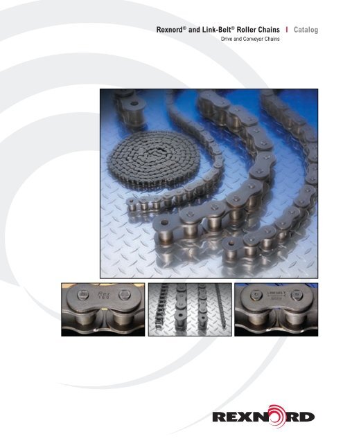
Link-Belt ® and <strong>Rex</strong>nord ® <strong>Roller</strong> <strong>Chain</strong>The best. By choice.AMany diverse elements go into eachlink of roller chain. Engineeringability. Material quality. Manufacturingtechnologies. Worker skills. And, everychain manufacturer has the sameopportunity to select the elementswhich constitute this product.<strong>Rex</strong>nord has chosen to produce onlythe best.Doing that requires the highest qualitymaterials, designed and improvedby the best engineering minds, andmanufactured by the industry’s mostadvanced and precise processes.It requires never standing still, butconstantly striving to improve ... andbacking that effort with the financial<strong>com</strong>mitment a continuing investment inquality requires.It requires insisting on tough internalquality standards that exceed even thedemanding minimums required by theAmerican National Standards Institute.It requires staying constantly in touchwith individual needs for roller chainthat will deliver long life and reliableperformance, even in the most limitedspace and under the harshest ofhostile environments.And it requires building on more than acentury of experience and tradition, toprovide products which deliver an extraedge in performance. Time after timeafter time.All of these factors add up to yourassurance that only the highest qualityroller chain bears the familiar Link-Belt ®and <strong>Rex</strong>nord ® symbol on its sidebars.It’s the best by choice.Superior qualitysupport for superiorquality productsNo matter how good it is, any rollerchain falls short of being the best ifit isn’t available when and where it’sneeded.So a wide network of stock-carryingdistributors maintain immediatelyavailable quantities of Link-Belt ® and<strong>Rex</strong>nord ® roller chain. To give you thebest, when and where you need it.In turn, vast Link-Belt ® and <strong>Rex</strong>nord ®warehouse inventories supportdistributor stocks, allowing for overnightdelivery in many cases.Further supplementing these efforts,strategically located Sales Offices andService Centers provide for direct,in-depth consultation. Each is staffedwith knowledgeable customer servicerepresentatives and sales specialists,who are able to aid in matters fromthe simplest application questions todeveloping <strong>com</strong>plete power transmissionsystems for specific applications.11A-1
Link-Belt ® and <strong>Rex</strong>nord ® <strong>Roller</strong> <strong>Chain</strong> Features and BenefitsAFeaturesBenefitsLink-Belt ® <strong>Rex</strong>nord ® Link-Belt ® <strong>Rex</strong>nord ®Holes quality is critical to maintaining the overall fatiguestrength of the chain.Precision pierced holesThis results in higher pin and bushing push outs andimproves fatigue strength.Extends chain life.Precision-controlled heat treatment processCritical for performance both in wear conditions andfatigue life.Consistent, high quality.Automatically assembled & preloadedEnsures precision <strong>com</strong>ponents, tight tolerances, anduniformity.Easy installation and alignment.Pre-lubricant is the most important lubrication a chainundergoes. All chains are hot dipped in a special chainlubricant that penetrates chain joints.Factory pre-lubricationProvides for minimal lubrication required at installation.Improves chain life in use or on the shelf.Through-hardened pins(from 80 pitch and upward)Case-hardened pinsProvides maximumstrength.Maximum wear life.Shot-peened <strong>com</strong>ponents &Drifted sidebars (ONLY forAPI Certified <strong>Chain</strong>s.)Improves overall fatiguestrength.Increased chain life.A-2
Link-Belt ® and <strong>Rex</strong>nord ® <strong>Roller</strong> <strong>Chain</strong>sDrivesStandard roller chain is broadly used inpower transmission applications rangingfrom general industrial applications todemanding oil field service to operationin such specialized areas as foodprocessing and heavy constructionequipment.Single and multiple standard rollerchains, available in many sizes, meetmost drive requirements. Specificationsare shown on pages B-1 through B-3.Double-pitch drive chains frequentlyprove the economical choice for slowerspeed drives on relatively long centers.For details, see page B-6.Modifications of these chains,developed for special operatingconditions, are described below.Corrosion resistance—Standard rollerchain made of stainless steel providesexcellent performance in applicationsrequiring high resistance to corrosiveattack. See page B-7.Shock resistance—Link-Belt ® SU and<strong>Rex</strong>nord ® Heavy "H" series roller chainprovides additional capacity to withstandintermittent shock loading. Featuresinclude improved fatigue resistance,thicker sidebars, and heat-treated pins.See page B-4.Extra clearance—Trans-Flex ® chain isdesigned for severe duty applications,such as in transit mixers, crawler drives,and other uses requiring delivery offull power despite recurrent sprocketmisalignment. See page B-6.1Available only in Link-Belt ® BrandULTR-O-LIFE TM O-ring roller chain 1 —Uses square cross sectional O-rings toseal in special lube while sealing outdirt, moisture and other contaminants.Available in 5/8” thru 11/4” pitch singlepitch series. Runs on standard ANSIsprockets. See page B-8.Side bow roller chain 1 —Extraclearance chain with ability to flex andtwist. Ideal for use on curved conveyorsor to transmit power under misalignedsprocket conditions. Available in 3/8” to 1”single pitch. See page D-15.Block chain 1 —Used in light load, lowspeed conveyors. Consisting of blocklinks (solid or laminated) and link platesjoined by pins, all block chains are 1”pitch and vary in width of block from3/16” to 1/2”. See page D-16.Hollow pin chain 1 —The truly versatileconveyor chain. Constructed withspecial pin links which have hollow pinsassembled in the pin plates. This uniquedesign allows easy insertion of crossrods or attachments to preassembledchain at desired spacings. Attachmentscan be repositioned without removingchain from conveyor. It is available insingle and double-pitch with or withoutCarrier <strong>Roller</strong>s. Full line of standardattachments available. 33 See page D-11.REDI-LUBE TM chain 1 —Self-lubricating,heavy walled, oil-impregnated, sinteredsteel bushings replace bushing androller of standard ANSI chain. Availablein single and double-pitch. Full rangeof standard attachments also available.See page D-9.Standard roller chain/single strandStandard roller chain/multiple strandDouble-pitch drive chainA-3A
AConveyorsStandard and double-pitch conveyor chains are availablewith a selection of attachments to ac<strong>com</strong>modate slats,angles, rollers, crossroads, and other conveying devices.You’ll find details on these widely used conveyor chains andattachments on pages D-3 through D-8.Conveyor chain design modifications to meet specificapplication requirements are described below.Restricted lubricationDouble-pitch roller chain with large-diameter rollers <strong>com</strong>binessmooth, quiet operation and long life. This modificationproves particularly useful in applications requiring minimumlubrication or where conditions make lubrication difficult. Seepage D-6.A-4
Link-Belt ® and <strong>Rex</strong>nord ® Drive <strong>Chain</strong>sStandard roller chainsGK K K KTPITCHEDCQuintuple StrandFAFig. 6448BB<strong>Chain</strong>Number<strong>Chain</strong>pitch,inchesAverageUltimatestrength,poundsMin.ANSIUTS,poundsWeightper foot,poundsDimensions, inchesA B C D E F G K TPage referencesHPratingsSprocketdata35-5 ∆ .375 10,500 8,790 1.06 1.03 1.11 .141 .200 s .19 .31 .35 .399 .05 C-11 C-1240-5 ∆ .500 18,500 15,625 1.97 1.45 1.52 .156 .313 .31 .41 .47 .566 .06 C-13 C-1450-5 ∆ .625 30,500 24,410 3.15 1.84 1.90 .200 .400 .38 .52 .59 .713 .08 C-17 C-1860-5 .750 42,500 35,150 5.02 2.30 2.40 .234 .469 .50 .60 .71 .897 .09 C-19 C-2080-5 1.000 72,500 62,500 8.21 2.92 3.03 .313 .625 .63 .75 .91 1.153 .13 C-21 C-22100-5 1.250 130,000 97,650 12.7 3.56 3.69 .375 .750 .75 .97 1.13 1.408 .16 C-23 C-24120-5 1.500 182,500 140,625 18.4 4.52 4.70 .438 .875 1.00 1.13 1.38 1.789 .19 C-25 C-26140-5 1.750 242,500 191,400 22.9 4.86 5.05 .500 1.000 1.00 1.31 1.56 1.924 .22 C-27 C-28160-5 2.000 340,000 250,000 31.9 5.82 6.00 .563 1.125 1.25 1.56 1.81 2.305 .25 C-29 C-30180-5 2.250 430,000 316,400 44.7 6.57 6.74 .688 1.406 1.41 1.85 2.14 2.592 .28 C-31 C-32200-5 2.500 500,000 390,625 53.9 7.22 7.56 .781 1.563 1.50 1.94 2.31 2.817 .31 C-33 C-34240-5 3.000 761,000 562,500 82.0 8.76 9.11 .938 1.875 1.88 2.44 2.81 3.458 .38 C-35 C-36Note: Dimensions and other Engineering Data are subject to change. Certified specifications of ordered product furnished upon request.GKK K K K TPITCHEDCFABSextuple StrandFig. 6449<strong>Chain</strong>Number<strong>Chain</strong>pitch,inchesAverageUltimatestrength,poundsMin.ANSIUTS,poundsWeightper foot,poundsDimensions, inchesA B C D E F G K TPage referencesHPratings35-6 ∆ .375 12,600 10,548 1.27 1.23 1.31 .141 .200 s .19 .31 .35 .399 .05 C-11 C-1240-6 ∆ .500 22,200 18,750 2.36 1.73 1.80 .156 .313 .31 .41 .47 .566 .06 C-13 C-1450-6 ∆ .625 36,600 29,292 3.77 2.19 2.25 .200 .400 .38 .52 .59 .713 .08 C-17 C-1860-6 .750 51,000 42,180 6.02 2.75 2.85 .234 .469 .50 .60 .71 .897 .09 C-19 C-2080-6 1.000 87,000 75,000 9.84 3.50 3.61 .313 .625 .63 .75 .91 1.153 .13 C-21 C-22100-6 1.250 156,000 117,180 15.2 4.26 4.39 .375 .750 .75 .97 1.13 1.408 .16 C-23 C-24120-6 1.500 219,000 168,750 22.0 5.42 5.59 .438 .875 1.00 1.13 1.38 1.789 .19 C-25 C-26140-6 1.750 291,000 229,680 27.4 5.82 6.01 .500 1.000 1.00 1.31 1.56 1.924 .22 C-27 C-28160-6 2.000 408,000 300,000 38.3 6.97 7.15 .563 1.125 1.25 1.56 1.81 2.305 .25 C-29 C-30180-6 2.250 516,000 379,680 53.6 7.87 8.04 .688 1.406 1.41 1.85 2.14 2.592 .28 C-31 C-32200-6 2.500 600,000 468,750 64.6 8.64 8.98 .781 1.563 1.50 1.94 2.31 2.817 .31 C-33 C-34240-6 3.000 913,200 675,000 98.4 10.50 10.84 .938 1.875 1.88 2.44 2.81 3.458 .38 C-35 C-36Sprocketdata∆ Available only in riveted construction. All other sizes may be furnished cottered or riveted.s Bushing diameter. <strong>Chain</strong> is rollerless.Minimum order quantities may be required in some parts.B-3
SU (Super Ultimate) and H (Heavy) Series <strong>Chain</strong>sBLink-Belt ® SU and <strong>Rex</strong>nord ® H series chains differ from standard roller chains in sidebar thickness and in pin material and heattreatment. The <strong>com</strong>bination of increased sidebar thickness and high hardness alloy through hardened pins results in greateraverage ultimate tensile strength ratings for the SU and H series chains. The SU and H chains are capable of withstandinghigher operating and intermittent shock loading without reduction of pin-bushing wear life.Multiple width SU and H series chains are available.SU and H series single strand roller chains operate on standard series roller chain sprockets. However, multiple strand heavyseries chains require sprockets with rows of teeth with wider spacing to ac<strong>com</strong>modate the thicker chain sidebars. See page B-5.GTPITCHEDFCABSU seriesFig. 6453<strong>Chain</strong> NumberAverage Min.<strong>Chain</strong>WeightDimensions, inchesUltimate ANSIpitch,per foot,Link-strength, UTS,<strong>Rex</strong>nord inchespoundsBelt ® A B C D E F G T® pounds poundsPagereferencesSprocketdata60H∆ 60H∆ .750 8,500 .176 1.23 .56 .65 .234 .469 .50 .60 .69 .13 C-2080SU 80H 1.000 17,500 .295 1.95 .69 .81 .313 .625 .63 .75 .91 .16 C-22100SU 100H 1.250 29,000 .427 2.84 .83 .95 .375 .750 .75 .97 1.13 .19 C-24120SU 120H 1.500 41,000 .636 4.14 1.02 1.19 .438 .875 1.00 1.13 1.38 .22 C-26140SU 140H 1.750 56,000 .759 5.17 1.08 1.27 .500 1.000 1.00 1.31 1.56 .25 C-28160SU 160H 2.000 70,000 1.028 6.92 1.29 1.47 .563 1.125 1.16 1.56 1.81 .28 C-30180SU 180H 2.250 95,000 1.413 9.54 1.45 1.62 .688 1.406 1.41 1.85 2.14 .31 C-32264 n 64S 2.500 135,000 2.023 12.45 1.674 2.018 .875 1.562 1.50 2.05 2.38 .38 C-34∆ Case hardened pin. 60n Replaces 250S and runs on 200 sprockets. Have dimensions certified for installation purposes.Note: Dimensions and other Engineering Data are subject to change. Certified specifications of ordered product furnished upon request.B-4
Sprocket Tooth Profile - Heavy Series <strong>Roller</strong> <strong>Chain</strong>Single strand heavy series roller chain can be used with ANSI standard series roller chain sprockets of corresponding pitch.However, multiple strand heavy series roller chain cannot be used with the standard series sprockets, be cause of the extrathickness of link plates on the heavy series. Sprockets for multiple strand heavy series roller chain must be made to order.Single StrandDimensions, inches<strong>Chain</strong> No. Pitch B E F R60H .750 0.459 0.375 0.272 0.79680SU 1.000 0.575 0.500 0.325 1.062100SU 1.250 0.692 0.625 0.380 1.327120SU 1.500 0.924 0.750 0.549 1.593140SU 1.750 0.924 0.875 0.487 1.858160SU 2.000 1.156 1.000 0.656 2.124180SU 2.250 1.301 1.125 0.740 2.392264 2.500 1.389 1.250 0.764 2.654SINGLEBFREPITCH DIA.BDouble StrandDimensions, inches<strong>Chain</strong> No. Pitch A B D E F G60H-2 .750 1.471 0.444 0.583 0.375 0.257 1.02780SU-2 1.000 1.839 0.556 0.727 0.500 0.306 1.283100SU-2 1.250 2.210 0.670 0.870 0.625 0.358 1.540120SU-2 1.500 2.820 0.894 1.032 0.750 0.519 1.926140SU-2 1.750 2.949 0.894 1.161 0.875 0.457 2.055160SU-2 2.000 3.555 1.119 1.317 1.000 0.619 2.436180SU-2 2.250 4.248 1.259 1.730 1.125 0.700 2.989264-2 2.500 4.426 1.344 1.738 1.250 0.719 3.082DOUBLEBADGEFTriple StrandDimensions, inches<strong>Chain</strong> No. Pitch A B D E F G60H-3 .750 2.498 0.444 0.583 0.375 0.257 1.02780SU-3 1.750 3.122 0.556 0.727 0.500 0.306 1.283100SU-3 1.250 3.750 0.670 0.870 0.625 0.358 1.540120SU-3 1.500 4.746 0.894 1.032 0.750 0.519 1.926140SU-3 1.750 5.004 0.894 1.161 0.875 0.457 2.055160SU-3 2.000 5.991 1.119 1.317 1.000 0.619 2.436180SU-3 2.250 7.237 1.259 1.730 1.125 0.700 2.989264-3 2.500 7.508 1.344 1.738 1.250 0.719 3.082TRIPLEBDGEAGFQuadruple StrandDimensions, inches<strong>Chain</strong> No. Pitch A B D E F G60H-4 .750 3.499 0.418 0.609 0.375 0.231 1.02780SU-4 1.000 4.375 0.526 0.757 0.500 0.276 1.283100SU-4 1.250 5.253 0.633 0.907 0.625 0.321 1.540120SU-4 1.500 6.626 0.848 1.078 0.750 0.473 1.926140SU-4 1.750 7.013 0.848 1.207 0.875 0.411 2.055160SU-4 2.000 8.371 1.063 1.373 1.000 0.563 2.436180SU-4 2.250 10.170 1.203 1.786 1.125 0.640 2.989264-4 2.500 10.524 1.278 1.804 1.250 0.653 3.082QUADRUPLEBADG G GEFNote: Dimensions subject to change. Certified dimensions of ordered material furnished on request.B-5
Link-Belt ® and <strong>Rex</strong>nord ® Drive <strong>Chain</strong>sDouble-pitch drive chainsCHAINPITCHBDouble-pitch drive chains are dimensionally identical to standard roller chains ofthe same strength, except for pitch length, which is “doubled”. With only one-halfthe number of pins, bushings , and rollers, double-pitch chains are lighter and moreeconomical than standard roller chains and are ideal for slow and moderate speedapplications, particularly when shaft centers are relatively long.Sprockets • Sprockets for double-pitch drive chains are normally furnished with twotimes the number of teeth required to contact the chain. As illustrated at right, therelationship between chain pitch and roller diameter results in adequate space for asecond set of teeth, which substantially increases sprocket life.ABCDETPITCHPITCHFGFig. 7031<strong>Chain</strong>Number<strong>Chain</strong>pitch,inchesAverageUltimatestrength,poundsMin.ANSIUTS,poundsWeightper foot,poundsDimensions, inchesA B C D E F G T2040 ∆ 1.000 3,900 .068 .28 .32 .38 .156 .313 .31 .39 .45 .06 C-37 C-382050 ∆ 1.250 6,300 .108 .41 .41 .48 .200 .400 .38 .48 .55 .08 C-39 C-402060 1.500 8,500 .162 .65 .50 .60 .234 .469 .50 .60 .71 .09 C-41 C-422060 H 1.500 8,500 .176 .79 .56 .64 .234 .469 .50 .60 .71 .13 C-41 C-422080 2.000 16,000 .275 1.10 .63 .74 .313 .625 .63 .75 .91 .13 C-43 C-44∆ Available only in riveted construction. All other sizes may be furnished cottered or riveted.Note: Dimensions and other Engineering Data are subject to change. Certified specifications of ordered product furnished upon request.Page referencesHPratingsSprocketdataExtra Clearance <strong>Chain</strong>sTrans-Flex ® straight-sidebar, extra-clearance roller chain is specially designed for severeservice on transit mixers and on crawler drives for shovels and cranes. Trans-Flex ® rollerchain permits twist of 8° and sidebend of 4" per 4-foot length. It delivers full power despiterecurrent sprocket misalignment. Trans-Flex ® chain operates on standard roller chainsprockets.ABCPITCHDTEFGFig. 8618C<strong>Chain</strong>Number<strong>Chain</strong>pitch,inchesAverageUltimatestrength,poundsMin.ANSIUTS,poundsWeightper foot,poundsDimensions, inchesA B C D E F G TPage referencesHPratingsSprocketdata140TF 1.750 48,500 .726 5.13 1.02 1.21 .500 1.000 1.00 1.43 1.56 .22 C-27 C-28160TF 2.000 68,000 .991 6.70 1.23 1.41 .563 1.125 1.25 1.64 1.81 .25 C-29 C-30160SU TF 2.000 70,000 s 1.028 7.40 1.29 1.47 .563 1.125 1.25 1.64 1.81 .28 C-31 C-32Cottered chains standard. Riveted construction can be furnished.n Horsepower ratings for flex-joint chains are 75% of the values shown in the rating tables.s Higher strength due to thru-hardened pins and side bars of heavier section.B-6
Link-Belt ® and <strong>Rex</strong>nord ® Drive <strong>Chain</strong>sCorrosion resistant chainsStainless Steel <strong>Chain</strong>s: Stainless steel chain sideplates are manufactured from AISI Type 300 chrome nickel stainless steel,with pins, bushings and rollers manufactured from AISI Type 400 stainless steel providing a balanced <strong>com</strong>bination of wear,corrosion and heat resistance adequate for most operating conditions.Where increased corrosion, wear and/or heat resistance is required, chains may be custom designed and manufactured with<strong>com</strong>ponents made from other grades of stainless steel <strong>com</strong>patible with the specific operating conditions.Plated <strong>Chain</strong>s: Standard carbon steel chain, assembled from parts individually plated with nickel, zinc or chrome, can befurnished to provide improved corrosion and/or wear characteristics <strong>com</strong>pared to a standard, unprotected carbon steel chain.Assembled carbon steel chains should not be plated because <strong>com</strong>ponent failure may occur.Sprockets: Standard carbon steel sprockets may be suitable for many applications; however, sprockets can be made from avariety of corrosion-resistant materials to suit application conditions. They are manufactured to the same applicable standardsand dimensions as sprockets for standard precision roller chains.BGTPITCHEDCFABFig. 6453Stainless Steel<strong>Chain</strong>Number<strong>Chain</strong>pitch,inchesAverageUltimatestrength,poundsMin.ANSIUTS,poundsWeightper foot,poundsDimensions, inchesA B C D E F G TPage referencesHPratingsSprocketdata25 SS ∆ .250 650 .017 .10 .15 .19 .091 .130 s .13 .20 .23 .03 C-09 C-1035 SS ∆ .375 1,550 .041 .22 .24 .27 .141 .200 s .19 .31 .34 .05 C-11 C-1240 SS ∆ .500 2,800 .068 .40 .32 .38 .156 .313 .31 .41 .45 .06 C-13 C-1441 SS ∆ .500 1,550 .049 .27 .27 .32 .141 .306 .25 .32 .38 .05 C-15 C-1650 SS ∆ .625 5,000 .108 .66 .41 .48 .200 .400 .38 .52 .59 .08 C-17 C-1860 SS .750 7,000 .162 1.03 .50 .60 .234 .469 .50 .60 .71 .09 C-19 C-2080 SN 1.000 12,000 .275 1.70 .63 .74 .313 .625 .63 .75 .91 .13 C-21 C-22100 SN 1.250 18,750 .401 2.82 .76 .89 .375 .750 .75 .97 1.13 .16 C-23 C-24∆ Available only in riveted construction. All other sizes may be furnished cottered or riveted.s Bushing diameter, chain is rollerless.V Horsepower ratings for stainless steel chains, when lubricated and operated at normal temperatures,are 25% of the values shown in the rating tables. See Table 3, page C-7.hCarbon Steel sprockets. Sprockets made from corrosion-resistant materials can be furnished on order.Note: Dimensions and other Engineering Data are subject to change. Certified specifications of ordered product furnished upon request.B-7
Link-Belt ® ULTR-O-LIFE O-Ring <strong>Chain</strong>Link-Belt ® ULTR-O-LIFE O-ring chain is built for applications where relubrication is nearly impossible or where contaminants areexcessive resulting in frequent and costly maintenance.BConstruction:Link-Belt ® O-ring chain uses O-rings to seal in special lubricants protecting the pin/bushing area virtually eliminating the need forrelubrication. The O-rings seal out dirt, moisture and other contaminants offering the ultimate protection against accelerated wear.Advantages:Link-Belt ® O-ring chain is easily maintained lasting three to ten times longer than standard series roller chains. Productivityand overall chain economy is dramatically increased while life-cycle costs are decreased. O-ring chains provide greater wearresistance, superior toughness and better operating performance in addition to enhancing equipment maintainability.HCDWABET<strong>Chain</strong>NumberPitchWidth<strong>Roller</strong>BushingDiam.Riv.EndtoCenterLineConn.EndtoOver-AllCenterLineDimensions, InchesOver-AllWidthLinkHeightPlateThicknessPinDiameterMinimumUltimateStrengthW D A B C H T E Lbs. Lbs.50-OR 0.625 0.38 0.40 0.47 0.55 0.94 0.59 0.08 0.20 4,882 0.7160-OR 0.750 0.50 0.47 0.56 0.66 1.13 0.70 0.09 0.23 7,030 1.0780-OR 1.000 0.63 0.63 0.72 0.81 1.44 0.95 0.13 0.31 12,500 1.8100-OR 1.250 0.75 0.75 0.86 0.98 1.70 1.16 0.16 0.38 19,530 2.0Note: Dimensions and other Engineering Data are subject to change. Certified specifications of ordered product furnished upon request.Aver.Wt.PerFootB-8
Drive EngineeringEngineering re<strong>com</strong>mendationsSeveral drive selections can usually be made for a givenapplication. Consideration of life expectancy, space, speed,cost and similar factors often suggest the better selection.Use the following re<strong>com</strong>mendations as a guide whenselecting roller chain drives.Horsepower ratings • The horsepower ratings listed onpages C-9 to C-35 apply directly to lubricated, single strand,standard and heavy series roller chains. Multiple strandchains are selected from the same rating tables by applyingthe factors in Table 2, page C-7. Stainless steel chain andother variations of standard roller chain are also selectedfrom the rating tables by applying the appropriate material ordesign variation factor from Table 3, page C-7.<strong>Chain</strong> pitch • Use the smallest pitch chain that will handlethe horsepower and load requirements. Single strand chainssatisfy most requirements and are usually more economical.Use small pitch multiple strand chains for high speed drivesor when quietness is desirable. This permits a larger numberof teeth in the driver sprocket and results in smoother driveoperation.Number of teeth for small sprockets • The re<strong>com</strong>mendedminimum number of teeth for the small sprocket varies withoperating conditions. The re<strong>com</strong>mended minimums are:Very slow speed drives........... 12 teethSlow speed drives.................. 17 teethModerate speed drives........... 21 teethHigh speed drives................... 25 teethHardened teeth • It is good practice to harden sprockets with25 teeth or less when applied to:Very low speed, heavily loaded drivesHigh speed drivesLarge ratio drivesAbrasive or corrosive conditionsFor additional information consult <strong>Rex</strong>nord Industries,Industrial <strong>Chain</strong> Chart North A : Variations America in chain speed due to chordal actionChart A : Variations in chain speed due to chordal actionV 2 - VPERCENT SPEED VARIATION = V 2 - 1 V 1 X 100 X 100V2 V2 V2R = PITCH RADIUS OF SPROCKET WHEELChart A : Variations in chain speed due to chordal actionR r = R XPITCH COS RADIUS 180°T OF SPROCKET WHEELTr =RNUMBERX COS 180° OF TEETHR = PITCH RADIUS T14N = RPM OF SPROCKET WHEELr = T R NUMBERX COS 180° OF TEETHMINIMUMTN = RPMCHAIN SPEED14 13T = NUMBER OF TEETHA MINIMUM14N = RPMMINIMUM CHAIN SPEED13 12A rA R CHAIN SPEED1312Vr1 =112πrN180°12Rr RV111= 2πrN V 1 = 2πrN1211 10T180° 12180° 1210T910T98MAXIMUMCHAIN SPEED8A7MAXIMUM MAXIMUMCHAIN CHAIN SPEED SPEEDA A76r R65r RV 2 = 2πRN180° r RV 2= 2πRN5180°12 V 2 = 2πRN124T12T180°43T3CHORDAL RISE AND32CHORDAL RISE AND2FALL OF CHAIN = R - rFALL CHORDAL OF CHAIN = RISE R - r AND211FALL OF CHAIN = R - r10055101015152020252530303535404045450NUMBER NUMBER OF OF TEETH TEETH IN SPROCKET IN SPROCKET0 5 10 15 20 25 30 35 40 45NUMBER OF TEETH IN SPROCKETChart A • Variations in chain speed due to chordal actionPERCENT SPEED VARIATION = V 2 - V 1 X 100CHAIN WEAR PER PITCH IN % OF PITCH7:1 RATIO7:1 RATIO(TWO 7:1 RATIO DRIVES)7:1 RATIO(TWO DRIVES)7:1 RATIOFig. 64607:1 RATIO(TWO DRIVES)Fig. 6460Chart B Chart • B : Variations in in useful chain life based life based on pitch Fig. on 6460 pitchelongation and number of teeth in large sprocketelongation Chart B and : Variations in useful chain life in based large on sprocketpitchChart B : Variations elongation in useful and chain number life of based teeth on in pitch large sprocketelongation and number of teeth in large sprocketELONGATION PER PITCH IN % OF PITCH = 200T6ELONGATION PER PITCH IN % INCHES OF PITCH = 2 = X P 2006ELONGATION PER PITCH IN % OF PITCH = 200T TT6ELONGATION P = CHAIN PITCH PER IN PITCH INCHESINCHES = 2 X PELONGATION PER PITCH IN INCHES = 2 X PT5T = NUMBER OF TEETH IN T LARGE SPROCKETP CHAIN PITCH IN INCHESP = CHAIN PITCH IN INCHES55T = NUMBERTOF= NUMBERTEETH IN LARGEOF TEETHSPROCKETIN LARGE SPROCKET4432100Chordal action • The rise and fall of each pitch of chain asit engages a sprocket is termed chordal action and causesrepeated chain speed variations. As illustrated by chart A,chordal action and speed variation decrease as the numberof teeth in the small sprocket is increased. Chordal actionbe<strong>com</strong>es negligible when 25 or more teeth are used andresults in smoother drive operation.Quietness • Speed and horsepower usually determine chainpitch. When quietness is essential, select a smaller pitch,wider chain and a driver sprocket with at least 25 teeth.Number of teeth for large sprockets • The number of teethin the large sprocket has an appreciable effect on the amountof joint wear (or pitch elongation) that can be ac<strong>com</strong>modatedby the chain before it tends to jump or ride over the teeth. Thisis illustrated by Chart B. Generally, a roller chain has reachedits useful wear life when the elongation per pitch is in therange of 2% to 3% of pitch. As show in the chart, this wouldresult in a maximum of 65-100 teeth for the large sprocket.This suggested maximum can be exceeded by making a moreconservative chain selection.When space limits the diameter of the large sprocket, it maybe necessary to select a smaller pitch, multiple strand chainto provide a sufficient number of teeth for the small sprocket.Drive ratio • The drive ratio is determined by the speeds ofthe driving and driven shafts. Properly engineered, drives withratios up to 10:1 will perform satisfactorily. However, doublereductiondrives with smaller ratios have better operatingcharacteristics and are often more economicalthan a large ratio, single-reduction drive.CHAIN CHAIN WEAR WEAR PER PER PITCH PITCH IN % IN OF % PITCH OF PITCH433221100 10 20 30 40 50 60 70 80 90 100 110 120 130 140 150 160 17010 20 30 40 50 60 70 80 90 100 110 120 130 140 150 160 17000 10 NUMBER 20 30 OF NUMBER TEETH 40 50IN OF 60 LARGE TEETH 70 SPROCKET 80IN 90 LARGE 100 110 SPROCKET 120 130 140 150 160 170NUMBER OF TEETH IN LARGE SPROCKETFig. 7314 Fig. 7314Fig. 7314C - 1C
CSelect relatively large diameter sprockets for 1:1 and 2:1 ratiodrives, especially if required to operate on horizontal centers.This will assure adequate distance between the two spans ofchain and prevent them from striking as wear accumulates.This is particularly important for drives on long, fixed centerswith the slack chain span on top.120° +RECOMMENDED NOT RECOMMENDEDFig. 6459Small pitch, multiple strand chains are Fig. 6459RECOMMENDED NOT RECOMMENDED generally moreFig. 6459economical RECOMMENDED Fig. 6459RECOMMENDED for large ratio drives NOT NOT on RECOMMENDED minimum RECOMMENDED centers. Largepitch, single strand chains are usually most economical forsmall ratio drives on long centers.Center distance • Sprocket centers must be more than 1/2the sum of the sprocket outside diameters to avoid toothinterference.A suggested minimum center distance would equal thediameter of the large sprocket plus half the diameter ofthe small sprocket. Drives so proportioned also assure theminimum suggested chain wrap of 120° on the small sprocket.120° +120°120°++TAUT SPANdD + dd 2ddD + d 2DMOVEMENTDDDFig. 6461D + d Fig.Fig.64616461Fig. 6461<strong>Chain</strong> tension • 2To obtain Fig. maximum 6461 chain life, makeD + d 2provisions to maintain proper chain tension. Make an initialadjustment after approximately the first 100 hours of operationto remove slack caused by initial elongation. Thereafter, thefrequency of periodic adjustments is governed by operatingconditions.Fig. 6458Fig. 6457Fig. 6457Fig. 6457Fig. 6457Fig. 6457The simplest method of adjusting chain tension is to providefor movement of one shaft. This method is <strong>com</strong>monly used fordrives operating from electric motors or internal <strong>com</strong>bustionengines since they can be mounted on adjustable baseplatesor slide rails.For fixed center drives, chain tension may be maintained byan automatic or manually adjusted chain tightener. Manuallyoperated chain tighteners must be frequently checked forproper adjustment.The idler sprocket should have a minimum of 17 teeth andshould be located adjacent to the driving sprocket so that atleast 3 teeth are in full engagement with the non-load-carryingspan of chain.If possible, provide enough adjustment of the chain tightenerto permit removal of two pitches of chain.AGTypical drive arrangements using chain tighteners are shownin the preferred drive arrangements below.Offset links may be used to adjust chain length when othermeans are not available. Single-pitch offset links and twopitchoffset assemblies can be supplied. Offset assembliesare re<strong>com</strong>mended for high speed or heavily loaded drives.<strong>Chain</strong> tension should be carefully maintained when thefollowing operating conditions exist:AAAFixed centersVertical or near vertical centersShock or pulsating loadsReversals in direction of rotation<strong>Chain</strong> length • When possible use a chain length with an evennumber of pitches to eliminate the need for an offset linkFixed centers • When sprocket centers cannot be adjusted,make a conservative drive selection by using a larger servicefactor than indicated. Also, provide good lubrication.Low speed drives • Ratings are not shown in the horsepowertables for extremely low speeds. For operation at thesespeeds, select drives on a chain strength basis. The ratio ofultimate chain strength to working load should be at least 6:1.Drives that operate at varying speeds such as powertake-off drives from a torque converter, from an engine with amulti-speed gear transmission, or from a constant horsepower,variable speed electric motor, should be selected on a chainstrength basis. The ratio of ultimate strength to maximumpeak load should not be less than 6:1. The selection shouldbe checked against the horsepower table for sufficient ratingat the normal operating speed.Drives operating from variable speed, variable horsepowerelectric motors should be selected to meet the maximum loadrequirements. In selecting the chain pitch, consideration mustbe given to the range of speeds involved.Preferred drive arrangements • The drive arrangementsillustrated below are desirable for optimum life of the drive.The preferred direction of rotation is indicated for eacharrangement, although arrangements A, B and C will operateBsatisfactorily in either direction.CFFFFEBBBDFig. 6455DDDCCCTAUT SPANTAUT SPANTAUT SPANTAUT SPANMOVEMENTMOVEMENTMOVEMENTMOVEMENTFig. 6458Fig. 6458Fig. 6458Fig. 6458GGGEEEFig. 6455Fig. 6455Fig. 6455Fig. 6455C - 2
Drive EngineeringOther arrangements • These arrangements are not generallyre<strong>com</strong>mended but they will give satisfactory service if carefullyattended and chain tension is accurately maintained.Operating conditions • The service factors listed in Table1 page C-7 are for normal operating conditions. Increasethese service factors to <strong>com</strong>pensate for any of the followingconditions:Heavy starting loadsFrequent starts and stopsLubrication inferior to method re<strong>com</strong>mendedShort or fixed centersVertical centers, particularly if the small sprocketis in the low positionTwo or more driven shaftsPeriodic load variation in a single revolutionReversals of drive rotationInertia strainsLarge ratiosLubrication • Adequate lubrication is necessary for optimumdrive life. A general guide to the re<strong>com</strong>mended method oflubrication is indicated in the horsepower rating tables. Thesere<strong>com</strong>mendations are based primarily on chain speed. For<strong>com</strong>plete lubrication data, refer to pages C-45 and C-46.Useful formulas • Formulas for calculating horsepower,torque, chain speed, working load and similar values are givenon page H-1.Drive selection procedureAlthough horsepower and speed are the prime considerationsfor selecting a drive, the following information is alsonecessary:Source of powerHorsepower to be transmittedSize and speed of driving shaftDriven equipmentSize and speed of driven shaftApproximate center distance between shaftsRelative position of shaftsSpace limitationsWith this information the selection procedure is as follows:Fig. 6456Establish the service factor • Select a service factor fromTable 1, page C-7, to <strong>com</strong>pensate for the loads imposedon the chain by the type of input power and the type ofequipment to be driven. If the exact driven equipment isnot listed, use the factor for equipment with similar opertingcharacteristics. Increase the service factor, if necessary, inaccordance with the instructions under “Operating Conditions”above.Establish the material or design variation factor • When avariation of standard roller chain is being selected (such asstainless steel chain for corrosion resistance), refer to Table3 on page C-7 and determine the appropriate variation factor.This factor <strong>com</strong>pensates for either the design or materialdifference so that a selection can be made from the standardroller chain rating table.Calculate the equivalent horsepower • Multiply thehorsepower to be transmitted by the service factor (and by thevariation factor, if applicable). This product is the equivalenthorsepower or the value on which the chain selection isbased.Select a trial chain • Standard roller chains are most<strong>com</strong>monly used and are selected from Chart C, page C-5.Single strand chains satisfy most drive requirements; however,multiple strand chains are often required for high speed drives,where space limits sprocket diameters, or where horsepowerrequirements exceed the capacity of single strand chains.Double-pitch chains are often used for slow speed,<strong>com</strong>paratively low horsepower drives on long centers. UseChart D, page C-6, to make a trial chain selection.To make a tentative chain selection, project a horizontal linefrom the horsepower scale and a vertical line from the speedscale based on the equivalent horsepower and the RPM ofthe small sprocket. The area in which the two lines intersectindicates the probable chain requirement.It is often desirable to evaluate selections based on the nextsmaller or next larger chain size, especially if the point ofintersection is near the border of an area.Determine the number of teeth for the small sprocket •The ratings in the horsepower tables apply to single strandchains.If a single strand standard roller chain or a double-pitchroller chain has been tentatively selected, refer directly tothe horsepower rating table for the trial chain (see pagesC-9 to C-43). In the column corresponding to the RPM ofthe small sprocket, find the rating nearest to the equivalenthorsepower. Follow this line horizontally to the left to findthe number of teeth required for the small sprocket.If a single multiple strand trial chain has been selected, therequired rating per strand must be determined in order touse the rating tables. The required table rating per strandis calculated by dividing the equivalent horsepower by theappropriate multiple strand factor from Table 2, page C-7.Now, refer to the horsepower rating table for the trial chain. Inthe column corresponding to the RPM of the small sprocket,find the rating nearest to the required rating per strand justcalculated. Follow this line horizontally to the left to find thenumber of teeth for the small sprocket.Check the small sprocket • Check the bore capacity of thesprocket selected, making sure it will ac<strong>com</strong>modate the drivingshaft. If the initial selection does not have adequate borecapacity, use a sprocket with larger number of teeth, or selecta drive using the next larger pitch of chain.Determine the drive ratio • Divide the speed of the fasterturning shaft by the speed of the slower turning shaft.C - 3C
CDetermine the number of teeth for the large sprocket •Multiply the drive ration by the number of teeth in the smallsprocket.If the drive is to operate in a restricted location, check thesprocket radii against the space limitation. Radial clearancerequired for each sprocket is equal to one-half the sum of itspitch diameter and the chain pitch. Encased drives requirean additional 3" radial clearance. If sufficient space is notavailable, consider a smaller pitch, multiple strand drive.Calculate exact center distance and chain length •Formulas for these calculations are on page C-8.Lubrication • The methods of lubrication shown in thehorsepower rating tables are based primarily on chain speed;however, the relative position of driving and driven shafts ofteninfluence the method of lubrication. Re<strong>com</strong>mendations and<strong>com</strong>plete lubrication information are given on pages C-45and C-46.Drive selection exampleProblemSelect a roller chain drive for the following conditions:Source of powerGearmotorHorsepower to betransmitted10 HPSize of driving shaft 2.438" diameterSpeed of driving shaft 100 RPMDriven equipmentBucket elevator uniformly fedSize of driven shaft 2.938" diameterSpeed of driven shaft 42 RPMApproximate center distance 24.00"Relative position of shafts On same horizontal planeSpace limitationsNoneSolutionService factor • The service factor listed in Table 1 on pageC-7 for a uniformly fed bucket elevator driven by a gearmotoris 1.0.Material or design variation factor • Since the listedconditions do not indicate the need for a variation in chainmaterial or design, select a standard roller chain. Therefore, avariation factor does not apply.Equivalent horsepower • The equivalent horsepower equals:10 x 1.0 = 10 HPTrial <strong>Chain</strong> • From Chart C, page C-5, note that theintersection of the 100 RPM vertical line and the 10 HPhorizontal line falls in the area for No. 100 chain. Thus, the trialchain is No. 100 single strand.Small sprocket • In the No. 100 rating table, page C-23, the100 RPM column lists 10.3 horsepower which correspondsclosely to the equivalent horsepower of 10 required for thisapplication. This rating is for single strand chain when usedwith a 17-tooth sprocket.Check the small sprocket • As shown in the rating table,the maximum bore of a 17-tooth No. 100 sprocket is largerthan the 2.438" bore required; therefore, the selection issatisfactory. Stock sprockets are readily available and areoften more economical.Drive ratio • The drive ratio equals:100 RPM = 2.38 to 142 RPMNumber of teeth in large sprocket • The number of teethin the large sprocket equals: 2.38 x 17 = 40.4 teeth. Use a40-tooth sprocket.Center distance and chain length • Using the formula onpage C-8, calculate the chain length as follows:A = 15.932-6.803 = .190002 x 24From Table 4, page C-8, select the next higher listed valueof .19081 for A. Corresponding factors for B, C and D are1.9633, .4389, and .5611, respectively. The chain length inpitches equals:1.9633 x 24 + (.4389 x 17) + (.5611 x 40) x 1.25 = 67.6011.25Use 68 pitches, which is the nearest even number.Calculate the exact center distance, using 68 pitches:E = 68 -(.4389 x 17) – (.5611 x 40) x 1.25 = 24.254"1.9633Lubrication • The No. 100 rating table specifies Type B bathor disc lubrication. For lubrication and bathing details, seepages C-45 to C-46.The drive selected for this application consists of:17-tooth No. 100 driving sprocket40-tooth No. 100 driven sprocket68 pitches of No. 100 roller chain for 24.254” shaft centers,and an oil-retaining casing foroil bath lubrication.C - 4
Drive Engineering ChartChart C • Trail selection of standard roller chainsEQUIVALENT HORSEPOWERNUMBER OF STRANDS4 3 2 120001000900800700600500400300200100908070605040302010987654321.9.8.7.6.515001000900800700600500400300200100908070605040302010987654321.9.8.7.6.5.41000900800700600500400300200100908070605040302010987654321.9.8.7.6.5.4.3600500400300200100908070605040302010987654321.9.8.7.6.5.4.3.2RPM OF SMALL SPROCKET100020 30 40 50 60 70 80 90100 200 300 400 500 600 700 8009002402001801601401201008060502000 3000 4000 5000 6000 8000CONSULT REXNORDiNDUSTRIAL CHAINFOR DRIVES IN THIS AREA403525C.4.3.2.11020 30 40 50 60 70 80 90100 200 300 400 500 600 700 80090010002000 3000 4000 5000 6000 8000 10000RPM OF SMALL SPROCKETFig. 7395C - 5
Chart D • Trial selection of double-pitch roller chains1300RPM OF SMALL SPROCKET100020 30 40 50 60 70 80 90100 200 300 400 500 600 700 8009002000 3000 4000 5000 6000 8000200C1009080706050403020CONSIDER STANDARD ROLLER CHAINOR CONSULT REXNORDINDUSTRIAL CHAINFOR DRIVES IN THIS AREAEQUIVALENT HORSEPOWER1098765432080220601.9.8.7.6.5.420502040.3.2.11020 30 40 50 60 70 80 90100 200 300 400 500 600 700 80090010002000 3000 4000 5000 6000 8000 10000C - 6RPM OF SMALL SPROCKETFig. 7396
Drive EngineeringTable 1 • Service FactorsDriven equipmentService FactorsInput powerInternal <strong>com</strong>bustion Electric motor Internal <strong>com</strong>bustionengine with or engine withhydraulic drive turbine mechanical driveAgitators, liquid stock................................................................... 1.0 1.0 1.2Beaters......................................................................................... 1.2 1.3 1.4Blowers, centrifugal...................................................................... 1.0 1.0 1.2Boat propellers............................................................................. 1.4 1.5 1.7Compressorscentrifugal................................................................................. 1.2 1.3 1.4reciprocating, 3 or more cylinders............................................ 1.2 1.3 1.4reciprocating, singular, 2 cylinders........................................... 1.4 1.5 1.7Conveyorsuniformly loaded or fed............................................................. 1.0 1.0 1.2not uniformly loaded or fed....................................................... 1.2 1.3 1.4reciprocating............................................................................. 1.4 1.5 1.7Cookers, cereal............................................................................. 1.0 1.0 1.2Crushers....................................................................................... 1.4 1.5 1.7Elevators, bucketuniformly loaded or fed............................................................. 1.0 1.0 1.2not uniformly loaded or fed....................................................... 1.2 1.3 1.4Fans, centrifugal........................................................................... 1.0 1.0 1.2Feedersrotary table................................................................................ 1.0 1.0 1.2apron, belt, screw, rotary vane................................................. 1.2 1.3 1.4reciprocating............................................................................. 1.4 1.5 1.7Generators.................................................................................... 1.0 1.0 1.2Grinders........................................................................................ 1.2 1.3 1.4Hoists............................................................................................ 1.2 1.3 1.4Kettles, brew................................................................................. 1.0 1.0 1.2Kilns and dryers, rotary................................................................ 1.2 1.3 1.4Lineshaftslight or normal service.............................................................. 1.0 1.0 1.2heavy service............................................................................ 1.2 1.3 1.4Machineryuniform load, nonreversing....................................................... 1.0 1.0 1.2moderate pulsating load, nonreversing.................................... 1.2 1.3 1.4severe impact or variable load, reversing................................ 1.4 1.5 1.7Millsball, pebble and tube................................................................ 1.2 1.3 1.4hammer, rolling......................................................................... 1.4 1.5 1.7Pumpscentrifugal................................................................................. 1.0 1.0 1.2reciprocating, 3 or more cylinders............................................ 1.2 1.3 1.4Screens, rotary, uniformly fed...................................................... 1.2 1.3 1.4CUniform load....................................... 1.0 1.0 1.2Basis for service factors: Moderate shock load........................ 1.2 1.3 1.4Heavy shock load............................... 1.4 1.5 1.7Table 2 • Multiple strand factorsNumber ofMultiple strandstrandsfactor2 1.73 2.54 3.35 4.16 5.07 or more Consult <strong>Rex</strong>nord Industrial <strong>Chain</strong>Table 3 • Material or design variation factorsVariationType of chain factor Speed limitationsTrans-Flex ® 1.00Stainless steel 4.00* Limit to slower operating speeds.* Assuming good lubrication; otherwise, make a conservative selection by using a largerfactor, or consult <strong>Rex</strong>nord Industrial <strong>Chain</strong>.C - 7
<strong>Chain</strong> length and center distance<strong>com</strong>putationsA center distance equal to the diameterof the large sprocket plus one-halfthe diameter of the small sprocket isthe suggested minimum for averageapplications.An even number of pitches is desirable.However, if an odd number of pitches isrequired, offset links are provided.These symbols are used for thefollowing formulas:e = desired sprocket centers ininchesE = exact sprocket centers in inchesg = pitch diameter of small sprocketin inchesG=pitch diameter of large sprocket ininchesN=actual length of chain in pitchesP=chain pitch in inchest=number of teeth in small sprocketT=number of teeth in large sprocketTo determine the sprocket centers andchain length of a given drive, calculatefactor A using the formula:A =G-g2 eRefer to Table 4 and select factors B, Cand D corresponding to value A or thenext higher value.The number of pitches in the chainequals the sum of the pitches betweensprockets and the pitches around thesprockets, orNumber of pitches = B e + C t + D TPThe chain length should equal an evennumber of pitches so that the chain willcouple without the use of an offset link.Therefore, select an even whole numbernearest to the calculated number ofpitches. Using this value as N, theexact sprocket centers is found by thefollowing formula:(N - C t - D T) PE =BCTable 4 • Factors for sprocket centers and chain lengthA B C D A B C D A B C D A B C D.00000 2.0000 .5000 .5000 .19937 1.9598 .4361 .5639 .39073 1.8410 .3722 .6278 .56641 1.6483 .3083 .6917.00436 2.0000 .4986 .5014 .20364 1.9581 .4347 .5653 .39474 1.8376 .3708 .6292 .57000 1.6433 .3069 .6931.00873 1.9999 .4972 .5028 .20791 1.9563 .4333 .5667 .39875 1.8341 .3694 .6306 .57358 1.6383 .3056 .6944.01309 1.9998 .4958 .5042 .21218 1.9545 .4319 .5681 .40275 1.8306 .3681 .6319 .57715 1.6333 .3042 .6958.01745 1.9997 .4944 .5056 .21644 1.9526 .4306 .5694 .40674 1.8271 .3667 .6333 .58070 1.6282 .3028 .6972.02181 1.9995 .4931 .5069 .22070 1.9507 .4292 .5708 .41072 1.8235 .3653 .6347 .58425 1.6231 .3014 .6986.02618 1.9993 .4917 .5083 .22495 1.9487 .4278 .5722 .41469 1.8199 .3639 .6361 .58779 1.6180 .3000 .7000.03054 1.9991 .4903 .5097 .22920 1.9468 .4264 .5736 .41866 1.8163 .3625 .6375 .59131 1.6129 .2986 .7014.03490 1.9988 .4889 .5111 .23345 1.9447 .4250 .5750 .42262 1.8126 .3611 .6389 .59482 1.6077 .2972 .7028.03926 1.9985 .4875 .5125 .23769 1.9427 .4236 .5764 .42657 1.8089 .3597 .6403 .59832 1.6025 .2958 .7042.04362 1.9981 .4861 .5139 .24192 1.9406 .4222 .5778 .43051 1.8052 .3583 .6417 .60182 1.5973 .2944 .7056.04798 1.9977 .4847 .5153 .24615 1.9385 .4208 .5792 .43445 1.8014 .3569 .6431 .60529 1.5920 .22931 .7069.05234 1.9973 .4833 .5167 .25038 1.9363 .4194 .5806 .43837 1.7976 .3556 .6444 .60876 1.5867 .2917 .7083.05669 1.9968 .4819 .5181 .25460 1.9341 .4181 .5819 .44229 1.7937 .3542 .6458 .61222 1.5814 .2903 .7097.06105 1.9963 .4806 .5194 .25882 1.9319 .4167 .5833 .44620 1.7899 .3528 .6472 .61566 1.5760 .2889 .7111.06540 1.9957 .4792 .5208 .26303 1.9296 .4153 .5847 .45010 1.7860 .3514 .6486 .61909 1.5706 .2875 .7125.06976 1.9951 .4778 .5222 .26724 1.9273 .4139 .5861 .45399 1.7820 .3500 .6500 .62251 1.5652 .2861 .7139.07411 1.9945 .4764 .5236 .27144 1.9249 .4125 .5875 .45787 1.7780 .3486 .6514 .62592 1.5598 .2847 .7153.07846 1.9938 .4750 .5250 .27564 1.9225 .4111 .5889 .46175 1.7740 .3472 .6528 .62932 1.5543 .2833 .7167.08281 1.9931 .4736 .5264 .27983 1.9201 .4097 .5903 .46561 1.7700 .3458 .6542 .63271 1.5488 .2819 .7181.08716 1.9924 .4722 .5278 .28402 1.9176 .4083 .5917 .46947 1.7659 .3444 .6556 .63608 1.5432 .2806 .7194.09150 1.9916 .4708 .5292 .28820 1.9151 .4069 .5875 .47332 1.7618 .3431 .6569 .63944 1.5377 .2792 .7208.09585 1.9908 .4694 .5306 .29237 1.9126 .4056 .5944 .47716 1.7576 .3417 .6583 .64279 1.5321 .2778 .7222.10019 1.9899 .4681 .5319 .29654 1.9100 .4042 .5958 .48099 1.7535 .3403 .6597 .64612 1.5265 .2764 .7236.10453 1.9890 .4667 .5333 .30071 1.9074 .4028 .5972 .48481 1.7492 .3389 .6611 .64945 1.5208 .2750 .7250.10887 1.9881 .4653 .5347 .30486 1.9048 .4014 .5986 .48862 1.7450 .3375 .6625 .65276 1.5151 .2736 .7264.11320 1.9871 .4639 .5361 .30902 1.9021 .4000 .6000 .49242 1.7407 .3361 .6639 .65606 1.5094 .2722 .7278.11754 1.9861 .4625 .5375 .31316 1.8994 .3986 .6014 .49622 1.7364 .3347 .6653 .65935 1.5037 .2708 .7292.12187 1.9851 .4611 .5389 .31730 1.8966 .3972 .6028 .50000 1.7321 .333 .6667 .66262 1.4979 .2694 .7306.12620 1.9840 .4597 .5403 .32144 1.8939 .3958 .6042 .50377 1.7277 .3319 .6681 .66588 1.4921 .2681 .7319.13053 1.9829 .4583 .5417 .32557 1.8910 .3944 .6056 .50754 1.7233 .3306 .6694 .66913 1.4863 .2667 .7333.13485 1.9817 .4569 .5431 .32969 1.8882 .3931 .6069 .51129 1.7188 .3292 .6708 .67237 1.4804 .2653 .7347.13917 1.9805 .4556 .5444 .33381 1.8853 .3917 .6083 .51504 1.7143 .3278 .6722 .67559 1.4746 .2639 .7361.14349 1.9793 .4542 .5458 .33792 1.8824 .3903 .6097 .51877 1.7098 .3264 .6736 .67880 1.4686 .2625 .7375.14781 1.9780 .4528 .5472 .34202 1.8794 .3889 .6111 .52250 1.7053 .3250 .6750 .68200 1.4627 .2611 .7389.15212 1.9767 .4514 .5486 .34612 1.8764 .3875 .6125 .52621 1.7007 .3236 .6764 .68518 1.4567 .2597 .7403.15643 1.9754 .4500 .5500 .35021 1.8733 .3861 .6139 .52992 1.6961 .3222 .6778 .68835 1.4507 .2583 .7417.16074 1.9740 .4486 .5514 .35429 1.8703 .3847 .6153 .53361 1.6915 .3208 .6792 .69151 1.4447 .2569 .7431.16505 1.9726 .4472 .5528 .35837 1.8672 .3833 .6167 .53730 1.6868 .3194 .6806 .69466 1.4387 .2556 .7444.16935 1.9711 .4458 .5542 .36244 1.8640 .3819 .6181 .54097 1.6821 .3181 .6819 .69779 1.4326 .2542 .7458.17365 1.9696 .4444 .5556 .36650 1.8608 .3806 .6194 .54464 1.6773 .3167 .6833 .70091 1.4265 .2528 .7472.17794 1.9681 .4431 .5569 .37056 1.8576 .3792 .6208 .54829 1.6726 .3153 .6847 .70401 1.4204 .2514 .7486.18224 1.9665 .4417 .5583 .37461 1.8544 .3778 .6222 .55194 1.6678 .3139 .6861 .70711 1.4142 .2500 .7500.18652 1.9649 .4403 .5597 .37865 1.8511 .3764 .6236 .55557 1.6629 .3125 .6875.19081 1.9633 .4389 .5611 .38268 1.8478 .3750 .6250 .55919 1.6581 .3111 .6889.19509 1.9616 .4375 .5625 .38671 1.8444 .3736 .6264 .56280 1.6532 .3097 .6903C - 8
Drive EngineeringNo. 25 chain • .250" pitchGTPITCHEDCFABFig. 6453Specifications and dimensions<strong>Chain</strong>NumberAverageultimatestrength,JointbearingareaWeightper footDimensions, inchespound ssq. in. pounds A B C D E F G T25 940 .017 .08 .15 .19 .090 .130∆ .13 .20 .23 .03Available only in riveted construction. All other sizes may be furnished cottered or riveted.∆ Bushing Diameter. <strong>Chain</strong> is rollerless.Note: Dimensions and other Engineering Data are subject to change. Certified specifications of ordered product furnished upon request.CRatingsNumber ofHorsepower for single strand chain sMaximumteeth,boreRPM of small sprocketin smallinchessprocket100 500 900 1200 1800 2500 3000 3500 4000 4500 5000 5500 6000 6500 7000 7500 8000 8500 9000 1000011 .313 0.05 0.23 0.39 0.50 0.73 0.98 1.15 1.32 1.38 1.16 0.99 0.86 0.75 0.67 0.60 0.54 0.49 0.45 0.41 0.3512 .375 0.06 0.25 0.43 0.55 0.80 1.07 1.26 1.45 1.57 1.32 1.12 0.97 0.86 0.76 0.68 0.61 0.56 0.51 0.47 0.4013 .438 0.06 0.27 0.47 0.60 0.87 1.17 1.38 1.58 1.77 1.49 1.27 1.10 0.96 0.86 0.77 0.69 0.63 0.57 0.53 0.4514 .563 0.07 0.30 0.50 0.65 0.94 1.27 1.49 1.71 1.93 1.66 1.42 1.23 1.08 0.96 0.86 0.77 0.70 0.64 0.59 0.5015 .563 0.08 0.32 0.54 0.70 1.01 1.36 1.61 1.85 2.08 1.84 1.57 1.36 1.20 1.06 0.95 0.86 0.78 0.71 0.65 0.5616 .563 0.08 0.34 0.58 0.76 1.09 1.46 1.72 1.98 2.23 2.03 1.73 1.50 1.32 1.17 1.05 0.94 0.86 0.78 0.72 0.6117 .625 0.09 0.37 0.62 0.81 1.16 1.56 1.84 2.11 2.38 2.22 1.90 1.64 1.44 1.28 1.14 1.03 0.94 0.86 0.79 0.6718 .750 0.09 0.39 0.66 0.86 1.24 1.66 1.96 2.25 2.53 2.42 2.07 1.79 1.57 1.39 1.25 1.12 1.02 0.93 0.86 0.7319 .813 0.10 0.41 0.70 0.91 1.31 1.76 2.07 2.38 2.69 2.62 2.24 1.94 1.70 1.51 1.35 1.22 1.11 1.01 0.93 0.7920 .875 0.10 0.44 0.74 0.96 1.38 1.86 2.19 2.52 2.84 2.83 2.42 2.10 1.84 1.63 1.46 1.32 1.20 1.09 1.00 0.8621 .875 0.11 0.46 0.78 1.01 1.46 1.96 2.31 2.66 2.99 3.05 2.60 2.26 1.98 1.76 1.57 1.42 1.29 1.17 1.08 0.9222 .938 0.11 0.48 0.82 1.07 1.53 2.06 2.43 2.79 3.15 3.27 2.79 2.42 2.12 1.88 1.69 1.52 1.38 1.26 1.16 0.9923 1.000 0.12 0.51 0.86 1.12 1.61 2.16 2.55 2.93 3.30 3.50 2.98 2.59 2.27 2.01 1.80 1.62 1.47 1.35 1.24 1.0624 1.063 0.13 0.53 0.90 1.17 1.69 2.27 2.67 3.07 3.46 3.73 3.18 2.76 2.42 2.15 1.92 1.73 1.57 1.44 1.32 1.1225 1.188 0.13 0.56 0.94 1.22 1.76 2.37 2.79 3.21 3.61 3.96 3.38 2.93 2.57 2.28 2.04 1.84 1.67 1.53 1.40 1.2028 1.250 0.15 0.63 1.07 1.38 1.99 2.68 3.15 3.62 4.09 4.54 4.01 3.47 3.05 2.70 2.42 2.18 1.98 1.81 1.66 1.4230 1.313 0.16 0.68 1.15 1.49 2.15 2.88 3.40 3.90 4.40 4.89 4.45 3.85 3.38 3.00 2.68 2.42 2.20 2.01 1.84 1.5732 1.500 0.17 0.73 1.23 1.60 2.30 3.09 3.64 4.18 4.72 5.25 4.90 4.25 3.73 3.30 2.96 2.67 2.42 2.21 2.03 1.7335 1.688 0.19 0.80 1.36 1.76 2.53 3.41 4.01 4.61 5.20 5.78 5.60 4.86 4.26 3.78 3.38 3.05 2.77 2.53 2.32 1.9840 1.875 0.22 0.92 1.57 2.03 2.93 3.93 4.64 5.32 6.00 6.68 6.85 5.93 5.21 4.62 4.13 3.73 3.38 3.09 2.83 2.42Lubrication type n A B Cs Ratings are based on a service factor of 1. For a <strong>com</strong>plete list of service factors, refer to Table 1, page C-7.The ratings listed above apply directly to lubricated, single strand, standard roller chains.To select chains that vary in design or material from standard roller chain, use the factors in Table 3, page C-7.n Type A: Manual or drip (Maximum chain speed 500 FPM)]Type B: Bath or disc (Maximum chain speed 3500 FPM)Type C: Forced (pump)C - 9
No. 25 sprockets • .250" pitchCDimensionsMaximumMaximum bore withOutside hub and standard Outside OutsideNumber Pitch Root diameter, groove keyseat, S Number Pitch Root diameter, Number Pitch Root diameter,of diameter, diameter, inches diameter, inches max., of diameter, diameter, inches of diameter, diameter, inchesteeth inches inches ∆ inches s inches teeth inches inches ∆ teeth inches inches ∆8 .653 .523 .754 .31 .250 .125 46 3.664 3.805 3.534 84 6.686 6.556 6.8329 .731 .601 .837 .41 .250 .125 47 3.743 3.885 3.613 85 6.766 6.636 6.91110 .809 .679 .919 .48 .250 .125 48 3.823 3.964 3.693 86 6.845 6.715 6.99111 .887 .757 1.002 .56 .313 .156 49 3.902 4.044 3.772 87 6.925 6.795 7.07012 .966 .836 1.083 .64 .375 .219 50 3.982 4.124 3.852 88 7.004 6.874 7.15013 1.045 .915 1.167 .73 .438 .219 51 4.061 4.203 3.931 89 7.084 6.954 7.23014 1.124 .994 1.246 .81 .563 .313 52 4.141 4.283 4.011 90 7.164 7.034 7.30915 1.203 1.073 1.326 .89 .563 .328 53 4.220 4.363 4.090 91 7.243 7.113 7.38916 1.282 1.152 1.407 .97 .563 .344 54 4.300 4.442 4.170 92 7.323 7.193 7.46817 1.361 1.231 1.487 1.06 .625 .375 55 4.379 4.522 4.249 93 7.402 7.272 7.54818 1.440 1.310 1.568 1.13 .750 .469 56 4.459 4.602 4.329 94 7.482 7.352 7.62819 1.519 1.389 1.648 1.22 .813 .500 57 4.538 4.681 4.408 95 7.561 7.431 7.70720 1.598 1.468 1.729 1.30 .875 .531 58 4.618 4.761 4.488 96 7.641 7.511 7.78721 1.678 1.548 1.809 1.38 .875 .563 59 4.697 4.841 4.567 97 7.720 7.590 7.86622 1.757 1.627 1.889 1.45 .938 .594 60 4.777 4.920 4.647 98 7.800 7.670 7.94623 1.836 1.706 1.969 1.53 1.000 .625 61 4.857 4.727 5.000 99 7.880 7.750 8.02624 1.915 1.785 2.049 1.61 1.063 .656 62 4.936 4.806 5.080 100 7.959 7.829 8.10525 1.995 1.865 2.129 1.69 1.188 .719 63 5.016 4.886 5.159 101 8.039 7.882 8.18526 2.074 1.944 2.209 1.77 1.250 .734 64 5.095 4.965 5.239 102 8.118 7.962 8.26427 2.154 2.024 2.289 1.86 1.250 .750 65 5.175 5.045 5.319 103 8.198 8.042 8.34428 2.233 2.103 2.389 1.94 1.250 .766 66 5.254 5.124 5.398 104 8.277 8.121 8.42429 2.312 2.182 2.449 2.02 1.250 .781 67 5.334 5.204 5.478 105 8.357 8.201 8.50330 2.392 2.262 2.529 2.09 1.313 .813 68 5.413 5.283 5.558 106 8.437 8.280 8.58331 2.471 2.341 2.609 2.19 1.375 .844 69 5.493 5.363 5.637 107 8.516 8.360 8.66232 2.551 2.421 2.688 2.25 1.500 .938 70 5.572 5.442 5.717 108 8.596 8.439 8.74233 2.630 2.500 2.768 2.34 1.563 .969 71 5.652 5.522 5.796 109 8.675 8.519 8.82234 2.710 2.580 2.848 2.41 1.625 1.000 72 5.732 5.602 5.876 110 8.755 8.599 8.90135 2.789 2.659 2.928 2.48 1.688 1.031 73 5.811 5.681 5.956 111 8.834 8.678 8.98136 2.869 2.739 3.008 2.58 1.750 1.063 74 5.891 5.761 6.035 112 8.914 8.758 9.06037 2.948 2.818 3.087 2.66 1.750 1.094 75 5.970 5.840 6.115 113 8.994 8.837 9.14038 3.028 2.898 3.167 2.73 1.813 1.156 76 6.050 5.920 6.195 114 9.073 8.917 9.22039 3.107 2.977 3.247 2.81 1.813 1.172 77 6.129 5.999 6.274 115 9.153 8.996 9.29940 3.187 3.057 3.327 2.89 1.875 1.188 78 6.209 6.079 6.354 116 9.232 9.076 9.37941 3.266 3.136 3.406 2.97 1.938 1.219 79 6.288 6.158 6.433 117 9.312 9.156 9.45842 3.346 3.216 3.486 3.05 2.000 1.250 80 6.368 6.238 6.513 118 9.391 9.235 9.53843 3.425 3.295 3.566 3.13 2.125 1.313 81 6.448 6.318 6.593 119 9.471 9.315 9.61844 3.505 3.375 3.646 3.20 2.188 1.344 82 6.527 6.397 6.672 120 9.550 9.394 9.69745 3.584 3.454 3.725 3.30 2.250 1.375 83 6.607 6.477 6.752 Larger sizes availableHub length thru boreRe<strong>com</strong>mended standard bore tolerances, keyseatdimensions, eccentricity tolerances, and similar data,page G-2.∆ Non-functional dimension that may vary with thetype of cutter used.s Based on maximum hub diameter.C - 10SprocketTypeNumberof teethLengththru bore,inches8 to 19 .50B 20 to 35 .6336 to 73 .7574 to 100 .88Tooth dimensionsT = .110” + .000”, –.007”
Drive EngineeringNo. 35 chain • .375" pitchGTKKKTPITCHEDEDCCFSpecifications and dimensions<strong>Chain</strong>Number<strong>Chain</strong>width,number ofstrandsAverageultimatestrength,poundsJointbearingarea, sq.in.AFig. 6453BWeightper foot,poundsABDimensions, inchesFig. 6447A B C D E F G K T35 Single 2,100 .041 .22 .24 .3135-2 Double 4,200 .082 .42 .45 .5035-3 Triple 6,450 .123 .62 .63 .70 .141 .200 ∆ .19 .31 .35 .399 .0535-4 Quadruple 8,600 .164 .82 .78 .9135-5 Quintuple 10,750 .205 1.06 1.03 1.1135-6 Sextuple 12,900 .246 1.27 1.23 1.31CAvailable only in riveted construction.∆ Bushing Diameter. <strong>Chain</strong> is rollerless.Note: Dimensions and other Engineering Data are subject to change. Certified specifications of ordered product furnished upon request.RatingsNumber ofHorsepower for single strand chain sMaximumteeth,boreRPM of small sprocketin smallinchessprocket100 500 900 1200 1800 2500 3000 3500 4000 4500 5000 5500 6000 6500 7000 7500 8000 8500 9000 1000011 .563 0.18 0.77 1.31 1.70 2.45 3.30 2.94 2.33 1.91 1.60 1.37 1.18 1.04 0.92 0.82 0.74 0.67 0.62 0.57 0.4812 .625 0.20 0.85 1.44 1.87 2.70 3.62 3.35 2.66 2.17 1.82 1.56 1.35 1.18 1.05 0.94 0.85 0.77 0.70 0.64 0.5513 .688 0.22 0.93 1.57 2.04 2.94 3.95 3.77 3.00 2.45 2.05 1.75 1.52 1.33 1.18 1.06 0.95 0.87 0.79 0.73 0.6214 .813 0.24 1.01 1.71 2.21 3.18 4.28 4.22 3.35 2.74 2.30 1.96 1.70 1.49 1.32 1.18 1.07 0.97 0.88 0.81 0.6915 .875 0.25 1.08 1.84 2.38 3.43 4.61 4.68 3.71 3.04 2.55 2.17 1.88 1.65 1.47 1.31 1.18 1.07 0.98 0.90 0.7716 .938 0.27 1.16 1.97 2.55 3.68 4.94 5.15 4.09 3.35 2.81 2.40 2.08 1.82 1.62 1.45 1.30 1.18 1.08 0.99 0.8517 1.063 0.29 1.24 2.10 2.73 3.93 5.28 5.64 4.48 3.67 3.07 2.62 2.27 2.00 1.77 1.58 1.43 1.30 1.18 1.09 0.9318 1.188 0.31 1.32 2.24 2.90 4.18 5.61 6.15 4.88 3.99 3.35 2.86 2.48 2.17 1.93 1.73 1.56 1.41 1.29 1.18 1.0119 1.250 0.33 1.40 2.37 3.07 4.43 5.95 6.67 5.29 4.33 3.63 3.10 2.69 2.36 2.09 1.87 1.69 1.53 1.40 1.28 1.1020 1.313 0.35 1.48 2.51 3.25 4.68 6.29 7.20 5.72 4.68 3.92 3.35 2.90 2.55 2.26 2.02 1.82 1.65 1.51 1.39 1.1821 1.438 0.37 1.56 2.64 3.42 4.93 6.63 7.75 6.15 5.03 4.22 3.60 3.12 2.74 2.43 2.17 1.96 1.78 1.62 1.49 1.2722 1.563 0.38 1.64 2.78 3.60 5.19 6.97 8.21 6.59 5.40 4.52 3.86 3.35 2.94 2.61 2.33 2.10 1.91 1.74 1.60 1.3723 1.688 0.40 1.72 2.92 3.78 5.44 7.31 8.62 7.05 5.77 4.83 4.13 3.58 3.14 2.79 2.49 2.25 2.04 1.86 1.71 1.4624 1.750 0.42 1.80 3.05 3.96 5.70 7.66 9.02 7.51 6.15 5.15 4.40 3.81 3.35 2.97 2.66 2.40 2.17 1.99 1.82 1.5625 1.813 0.44 1.88 3.19 4.13 5.95 8.00 9.43 7.99 6.54 5.48 4.68 4.05 3.56 3.16 2.82 2.55 2.31 2.11 1.94 1.6528 2.125 0.50 2.12 3.61 4.67 6.73 9.05 10.7 9.47 7.75 6.49 5.55 4.81 4.22 3.74 3.35 3.02 2.74 2.50 2.30 1.9630 2.281 0.54 2.29 3.89 5.03 7.25 9.74 11.5 10.5 8.59 7.20 6.15 5.33 4.68 4.15 3.71 3.35 3.04 2.77 2.55 2.1732 2.500 0.58 2.45 4.17 5.40 7.77 10.4 12.3 11.6 9.47 7.93 6.77 5.87 5.15 4.57 4.09 3.69 3.35 3.06 2.81 035 2.781 0.64 2.70 4.59 5.95 8.56 11.5 13.6 13.2 10.8 9.08 7.75 6.72 5.90 5.23 4.68 4.22 3.83 3.50 3.21 040 3.250 0.73 3.12 5.30 6.87 9.89 13.3 15.7 16.2 13.2 11.1 9.47 8.21 7.20 6.39 5.72 5.15 4.68 0Lubrication type n A B Cs Ratings are based on a service factor of 1. For a <strong>com</strong>plete list of service factors, refer to Table 1, page C-7.The ratings listed above apply directly to lubricated, single strand, standard roller chains.For multiple strand chains, apply the factors shown in the table at right. To select chains that vary in designor material from standard roller chain, use the factors in Table 3, page C-7.n Type A: Manual or drip (Maximum chain speed 370 FPM)]Type B: Bath or disc (Maximum chain speed 2800 FPM)Type C: Forced (pump)Multiple strand factorsNumber of Multiple strandstrandsfactor2 1.73 2.54 3.35 4.16 5.07 or more Consult <strong>Rex</strong>nordIndustrial <strong>Chain</strong>C - 11
No. 35 sprockets • .375" pitchDimensionsCMaximumMaximum bore withOutside hub and standard Outside OutsideNumber Pitch Root diameter, groove keyseat, S Number Pitch Root diameter, Number Pitch Root diameter,of diameter, diameter, inches diameter, inches max., of diameter, diameter, inches of diameter, diameter, inchesteeth inches inches ∆ inches s inches teeth inches inches ∆ teeth inches inches ∆8 .980 .780 1.130 .50 .250 .125 46 5.495 5.295 5.708 84 10.029 9.829 10.2479 1.096 .896 1.255 .63 .375 .250 47 5.614 5.414 5.827 85 10.148 9.948 10.36710 1.214 1.014 1.379 .75 .500 .313 48 5.734 5.534 5.946 86 10.268 10.086 10.48611 1.331 1.131 1.502 .86 .563 .344 49 5.853 5.653 6.066 87 10.387 10.187 10.60612 1.449 1.249 1.625 .98 .625 .406 50 5.972 5.772 6.186 88 10.506 10.306 10.72513 1.567 1.367 1.746 1.11 .688 .438 51 6.091 5.891 6.305 89 10.626 10.426 10.84414 1.685 1.485 1.868 1.23 .813 .500 52 6.211 6.011 6.425 90 10.745 10.545 10.96415 1.804 1.604 1.989 1.36 .875 .531 53 6.330 6.130 6.544 91 10.864 10.664 11.08316 1.922 1.722 2.110 1.47 .938 .594 54 6.449 6.249 6.664 92 10.984 10.784 11.20317 2.041 1.841 2.231 1.59 1.063 .656 55 6.569 6.369 6.783 93 11.103 10.903 11.32218 2.159 1.959 2.352 1.72 1.188 .719 56 6.688 6.488 6.903 94 11.222 11.022 11.44119 2.278 2.078 2.472 1.84 1.250 .750 57 6.807 6.607 7.022 95 11.342 11.142 11.56120 2.397 2.197 2.593 1.95 1.313 .813 58 6.927 6.727 7.142 96 11.461 11.261 11.68021 2.516 2.316 2.713 2.08 1.438 .906 59 7.046 6.846 7.261 97 11.580 11.380 11.80022 2.635 2.435 2.833 2.20 1.563 .969 60 7.165 6.965 7.381 98 11.700 11.500 11.91923 2.754 2.554 2.953 2.31 1.688 1.031 61 7.284 7.084 7.500 99 11.819 11.619 12.03824 2.873 2.673 3.074 2.44 1.750 1.094 62 7.404 7.204 7.619 100 11.938 11.738 12.15825 2.992 2.792 3.194 2.56 1.813 1.156 63 7.523 7.323 7.739 101 12.058 11.858 12.27726 3.111 2.911 3.314 2.67 1.938 1.219 64 7.642 7.442 7.858 102 12.177 11.977 12.39727 3.230 3.030 3.434 2.80 2.000 1.250 65 7.762 7.562 7.978 103 12.297 12.097 12.51928 3.349 3.149 3.553 2.92 2.125 1.313 66 7.881 7.681 8.097 104 12.416 12.216 12.63529 3.468 3.268 3.673 3.03 2.250 1.375 67 8.000 7.800 8.217 105 12.535 12.335 12.75530 3.588 3.388 3.793 3.16 2.281 1.438 68 8.120 7.920 8.336 106 12.655 12.455 12.87431 3.707 3.507 3.913 3.28 2.375 1.500 69 8.239 8.039 8.456 107 12.774 12.574 12.99432 3.826 3.626 4.032 3.39 2.500 1.563 70 8.358 8.158 8.575 108 12.893 12.693 13.11333 3.945 3.745 4.152 3.52 2.625 1.625 71 8.478 8.278 8.695 109 13.013 12.813 13.23234 4.064 3.864 4.272 3.64 2.750 1.688 72 8.597 8.397 8.814 110 13.132 12.932 13.35235 4.183 3.983 4.392 3.75 2.781 1.750 73 8.716 8.516 8.934 111 13.251 13.051 13.47136 4.303 4.103 4.511 3.88 2.875 1.813 74 8.836 8.636 9.053 112 13.371 13.171 13.59037 4.422 4.222 4.631 4.00 3.000 1.875 75 8.955 8.755 9.172 113 13.490 13.290 13.71038 4.541 4.341 4.751 4.11 3.125 1.938 76 9.074 8.874 9.291 114 13.609 13.409 13.82939 4.660 4.460 4.870 4.23 3.188 1.969 77 9.194 8.994 9.411 115 13.729 13.529 13.94940 4.780 4.580 4.990 4.36 3.250 2.000 78 9.313 9.113 9.531 116 13.848 13.648 14.06841 4.899 4.699 5.109 4.47 3.281 2.063 79 9.432 9.232 9.650 117 13.969 13.768 14.18742 5.018 4.818 5.229 4.59 3.375 2.125 80 9.552 9.352 9.770 118 14.087 13.887 14.30743 5.137 4.937 5.349 4.72 3.438 2.156 81 9.671 9.471 9.889 119 14.206 14.006 14.42644 5.257 5.507 5.468 4.83 3.500 2.188 82 9.790 9.590 10.008 120 14.326 14.126 14.54645 5.376 5.176 5.588 4.95 3.625 2.250 83 9.910 9.710 10.128 Larger sizes availableHub length thru bore, inchesSprocketTypeBCC - 12Number<strong>Chain</strong> width, number of strandsof teeth 1 2 3 4 5 68 to 19 .75 1.25 1.75 2.13 2.63 3.1320 to 44 .88 1.38 1.88 2.25 2.75 3.2545 to 102 1.00 1.50 2.00 2.38 2.88 3.38103 to 120 1.25 1.75 2.25 2.63 3.13 3.6341 to 80 1.75 2.00 2.25 2.50 2.75 3.0081 to 120 2.00 2.25 2.50 2.75 3.00 3.25Tooth dimensions, inchesDimension<strong>Chain</strong> width, number of strands1 2 3 4 5 6T .168 .162 .162 .149 .149 .149L ... .560 .958 1.343 1.741 2.139K ... .399 .399 .399 .399 .399Tolerancesfor T and LRe<strong>com</strong>mended standard bore tolerances, keyseat dimensions, eccentricity tolerances, and similar data, page G-2.∆ Non-functional dimension that may vary with the type of cutter used.s Based on maximum hub diameter.Machined sprockets ......... +.000”, –.008”Hot rolled steel plate sprockets orunfinished forgings ....... +.000”, –.027”
Drive engineeringNo. 40 chain • .500" pitchGTKKKTPITCHEDEDCCFABABFig. 6447Fig. 6453Specifications and dimensions<strong>Chain</strong>Number<strong>Chain</strong> width,number ofstrandsAverageultimatestrength,poundsJointbearingarea,sq.in.Weightper foot,poundsDimensions, inchesA B C D E F G K T40 Single 3,700 .068 .39 .32 .3840-2 Double 7,400 .136 .79 .60 .6740-3 Triple 11,100 .204 1.18 .89 .95 .156 .313 .31 .41 .47 .566 .0640-4 Quadruple 14,800 .272 1.57 1.17 1.2340-5 Quintuple 18,500 .340 1.97 1.45 1.5240-6 Sextuple 22,200 .408 2.36 1.73 1.80Available only in riveted construction.Note: Dimensions and other Engineering Data are subject to change. Certified specifications of ordered product furnished upon request.CRatingsNumber ofteeth,in smallsprocketMaximumboreinchesHorsepower for single strand chain sRPM of small sprocket50 100 200 300 400 500 700 1000 1200 1400 1600 1800 2400 3000 3500 4000 5000 6000 7000 800011 .750 0.23 0.43 0.80 1.16 1.50 1.83 2.48 3.42 4.03 4.63 5.22 4.66 3.03 2.17 1.72 1.41 1.01 0.77 0.61 0.5012 .844 0.25 0.47 0.88 1.27 1.65 2.01 2.73 3.76 4.43 5.09 5.74 5.31 3.45 2.47 1.96 1.60 1.15 0.87 0.69 0.5713 1.000 0.28 0.52 0.96 1.39 1.80 2.20 2.97 4.10 4.83 5.55 6.26 5.99 3.89 2.79 2.21 1.81 1.29 0.98 0.78 0.6414 1.188 0.30 0.56 1.04 1.50 1.95 2.38 3.22 4.44 5.23 6.01 6.78 6.70 4.35 3.11 2.47 2.02 1.45 1.10 0.87 0.7115 1.250 0.32 0.60 1.12 1.62 2.10 2.56 3.47 4.78 5.64 6.47 7.30 7.43 4.82 3.45 2.74 2.24 1.60 1.22 0.97 0.7916 1.375 0.35 0.65 1.20 1.74 2.25 2.75 3.72 5.13 6.04 6.94 7.83 8.18 5.31 3.80 3.02 2.47 1.77 1.34 1.07 0.8717 1.500 0.37 0.69 1.29 1.85 2.40 2.93 3.97 5.48 6.45 7.41 8.36 8.96 5.82 4.17 3.31 2.71 1.94 1.47 1.17 0.9618 1.625 0.39 0.73 1.37 1.97 2.55 3.12 4.22 5.82 6.86 7.88 8.89 9.76 6.34 4.54 3.60 2.95 2.11 1.60 1.27 019 1.750 0.42 0.78 1.45 2.09 2.71 3.31 4.48 6.17 2.27 8.36 9.42 10.5 6.88 4.92 3.91 3.20 2.29 1.74 1.38 020 1.875 0.44 0.82 1.53 2.21 2.86 3.50 4.73 6.53 7.69 8.83 9.96 11.1 7.43 5.31 4.22 3.45 2.47 1.88 1.49 021 2.063 0.46 0.87 1.62 2.33 3.02 3.69 4.99 6.88 8.11 9.31 10.5 11.7 7.99 5.72 4.54 3.71 2.66 2.02 1.60 022 2.188 0.49 0.91 1.70 2.45 3.17 3.88 5.25 7.23 8.52 9.79 11.0 12.3 8.57 6.13 4.87 3.98 2.85 2.17 1.72 023 2.250 0.51 0.96 1.78 2.57 3.33 4.07 5.51 7.59 8.94 10.3 11.6 12.9 9.16 6.55 5.20 4.26 3.05 2.32 1.84 024 2.250 0.54 1.00 1.87 2.69 3.48 4.26 5.76 7.95 9.36 10.8 12.1 13.5 9.76 6.99 5.54 4.54 3.25 2.47 1.96 025 2.281 0.56 1.05 1.95 2.81 3.64 4.45 6.02 8.30 9.78 11.2 12.7 14.1 10.4 7.43 5.89 4.82 3.45 2.63 028 2.625 0.63 1.18 2.20 3.18 4.11 5.03 6.81 9.39 11.1 12.7 14.3 15.9 12.3 8.80 6.99 5.72 4.09 3.11 030 2.750 0.68 1.27 2.38 3.42 4.43 5.42 7.33 10.1 11.9 13.7 15.4 17.2 13.6 9.76 7.75 6.34 4.54 3.45 032 3.000 0.73 1.36 2.55 3.67 4.75 5.81 7.86 10.8 12.8 14.7 16.5 18.4 15.0 10.8 8.54 6.99 5.00 035 3.563 0.81 1.50 2.81 4.04 5.24 6.40 8.66 11.9 14.1 16.2 18.2 20.3 17.2 12.3 9.76 7.99 5.72 040 3.781 0.93 1.74 3.24 4.67 6.05 7.39 10.0 13.8 16.3 18.7 21.1 23.4 21.0 15.0 11.9 9.76 6.99 0Lubrication type n A B Cs Ratings are based on a service factor of 1. For a <strong>com</strong>plete list of service factors.Refer to Table 1, page C-7.The ratings listed above apply directly to lubricated, single strand, standard roller chains.For multiple strand chains, apply the factors shown in the table at right. To select chains that vary in designor material from standard roller chain, use the factors in Table 3, page C-7.n Type A: Manual or drip (Maximum chain speed 300 FPM)Type B: Bath or disc (Maximum chain speed 2300 FPM)Type C: Forced (pump)Multiple strand factorsNumber ofstrandsMultiple strandfactor2 1.73 2.54 3.35 4.16 5.07 or more Consult <strong>Rex</strong>nordIndustrial <strong>Chain</strong>C - 13
No. 40 sprockets • .500" pitchDimensionsCMaximumMaximum bore withOutside hub and standard Outside OutsideNumber Pitch Root diameter, groove keyseat, S Number Pitch Root diameter, Number Pitch Root diameter,of diameter, diameter, inches diameter, inches max., of diameter, diameter, inches of diameter, diameter, inchesteeth inches inches ∆ inches s inches teeth inches inches ∆ teeth inches inches ∆8 1.307 .995 1.507 .67 .375 .188 46 7.327 7.015 7.609 84 13.372 13.060 13.6639 1.462 1.150 1.674 .84 .500 .313 47 7.486 7.174 7.769 85 13.531 13.219 13.82210 1.618 1.306 1.839 1.00 .625 .406 48 7.645 7.333 7.927 86 13.690 13.378 13.98211 1.775 1.463 2.003 1.17 .750 .469 49 7.804 7.492 8.088 87 13.849 13.537 14.14112 1.932 1.620 2.166 1.33 .844 .516 50 7.963 7.651 8.247 88 14.008 13.696 14.30013 2.089 1.777 2.329 1.50 1.000 .625 51 8.122 7.810 8.407 89 14.168 13.856 14.45914 2.247 1.935 2.491 1.66 1.188 .719 52 8.281 7.969 8.566 90 14.327 14.015 14.61815 2.405 2.093 2.653 1.81 1.250 .750 53 8.440 8.128 8.725 91 14.486 14.174 14.77716 2.563 2.251 2.814 1.98 1.375 .844 54 8.599 8.287 8.885 92 14.645 14.333 14.93717 2.721 2.409 2.975 2.14 1.500 .938 55 8.758 8.446 9.044 93 14.804 14.492 15.09618 2.879 2.567 3.136 2.30 1.625 1.000 56 8.917 8.605 9.203 94 14.963 14.651 15.25519 3.038 2.726 3.297 2.45 1.750 1.063 57 9.076 8.764 9.363 95 15.122 14.810 15.41420 3.196 2.884 3.457 2.63 1.875 1.188 58 9.236 8.924 9.522 96 15.281 14.969 15.57321 3.355 3.043 3.618 2.78 2.063 1.281 59 9.395 9.083 9.681 97 15.440 15.128 15.73322 3.513 3.201 3.778 2.94 2.188 1.344 60 9.554 9.242 9.841 98 15.600 15.288 15.89223 3.672 3.360 3.938 3.09 2.250 1.375 61 9.713 9.401 10.000 99 15.759 15.447 16.05124 3.831 3.519 4.098 3.27 2.250 1.406 62 9.872 9.560 10.159 100 15.918 15.606 16.21025 3.989 3.677 4.258 3.42 2.281 1.438 63 10.031 9.719 10.318 101 16.077 15.765 16.37026 4.148 3.836 4.418 3.58 2.313 1.469 64 10.190 9.878 10.478 102 16.236 15.924 16.52927 4.307 3.995 4.578 3.73 2.375 1.500 65 10.349 10.037 10.637 103 16.395 16.083 16.68828 4.466 4.154 4.738 3.91 2.625 1.625 66 10.508 10.196 10.796 104 16.555 16.243 16.84729 4.625 4.313 4.898 4.06 2.750 1.688 67 10.667 10.355 10.956 105 16.714 16.402 17.00630 4.783 4.471 5.057 4.22 2.750 1.750 68 10.826 10.514 11.115 106 16.873 16.561 17.16631 4.942 4.630 5.217 4.38 2.813 1.781 69 10.986 10.674 11.274 107 17.032 16.720 17.32432 5.101 4.789 5.377 4.55 3.000 1.875 70 11.145 10.833 11.434 108 17.191 16.879 17.48333 5.260 4.948 5.536 4.70 3.375 2.125 71 11.304 10.992 11.593 109 17.350 17.038 17.64334 5.419 5.107 5.696 4.86 3.438 2.156 72 11.463 11.151 11.752 110 17.509 17.197 17.80335 5.578 5.266 5.856 5.02 3.563 2.219 73 11.622 11.310 11.911 111 17.669 17.357 17.96136 5.737 5.425 6.015 5.17 3.625 2.250 74 11.781 11.469 12.071 112 17.828 17.516 18.12037 5.896 5.584 6.175 5.34 3.688 2.281 75 11.940 11.628 12.230 113 17.987 17.675 18.28038 6.055 5.743 6.334 5.50 3.750 2.313 76 12.099 11.787 12.389 114 18.146 17.834 18.43939 6.214 5.902 6.494 5.66 3.750 2.344 77 12.258 11.946 12.548 115 18.305 17.993 18.59840 6.373 6.061 6.653 5.81 3.781 2.375 78 12.417 12.105 12.708 116 18.464 18.152 18.75741 6.532 6.220 6.813 5.97 3.813 2.406 79 12.577 12.265 12.867 117 18.623 18.311 18.91742 6.691 6.379 6.972 6.14 4.000 2.500 80 12.736 12.424 13.026 118 18.783 18.471 19.07643 6.850 6.538 7.132 6.30 4.250 2.625 81 12.895 12.583 13.185 119 18.942 18.630 19.23544 7.009 6.697 7.291 6.45 4.500 2.750 82 13.054 12.742 13.345 120 19.101 18.789 19.39445 7.168 6.856 7.451 6.61 4.750 2.875 83 13.213 12.901 13.504 Larger sizes availableHub length thru bore, inchesSprocketTypeBCC - 14Number ofteeth<strong>Chain</strong> width, number of strands1 2 3 4 5 68 to 19 .88 1.50 2.13 2.75 3.38 4.0020 to 46 1.00 1.63 2.25 2.88 3.50 4.1347 to 76 1.13 1.75 2.38 3.00 3.63 4.2577 to 90 1.25 2.00 2.63 3.25 3.88 4.5091 to 120 1.38 2.25 2.88 3.50 4.13 4.7530 to 60 1.75 2.13 2.50 3.25 3.63 4.0061 to 82 2.00 2.38 2.75 3.50 3.88 4.2583 to 120 2.25 2.63 3.00 3.75 4.13 4.50Tooth dimensions, inchesDimension<strong>Chain</strong> width, number of strands1 2 3 4 5 6T .284 .275 .275 .256 .256 .256L ... .841 1.407 1.954 2.520 3.086K ... .566 .566 .566 .566 .566Tolerancesfor T and LRe<strong>com</strong>mended standard bore tolerances, keyseat dimensions, eccentricity tolerances, and similar data, page G-2.∆ Non-functional dimension that may vary with the type of cutter used.s Based on maximum hub diameter.Machined sprockets ......... +.000”, –.009”Hot rolled steel plate sprockets orunfinished forgings ....... +.000”, –.035”
Drive EngineeringNo. 41 chain • .500" pitchGGTTPITCHPITCHEEDDCCFA FBABFig. 6453Fig. 6453Specifications and dimensionsC<strong>Chain</strong>numberAverageultimatestrength,poundsJointbearingareaSq. in.Weightper foot,poundsDimensions, inchesA B C D E F G T41 2,000 .049 .27 .27 .32 .141 .306 .25 .32 .38 .05Available only in riveted construction.Note: Dimensions and other Engineering Data are subject to change. Certified specifications of ordered product furnished upon request.RatingsNumber ofteeth,in smallsprocketMaximumboreinchesHorsepower for single strand chain sRPM of small sprocket50 100 200 300 400 500 700 1000 1200 1400 1600 1800 2400 3000 3500 4000 5000 6000 7000 800011 .875 0.13 0.24 0.44 0.64 0.82 1.01 1.37 1.88 1.71 1.36 1.11 0.93 0.61 0.43 0.34 0.28 0.20 0.15 0.12 0.1012 .969 0.14 0.26 0.49 0.70 0.91 1.11 1.50 2.07 1.95 1.55 1.27 1.06 0.69 0.49 0.39 0.32 0.23 0.17 0.14 0.1113 1.125 0.15 0.28 0.53 0.76 0.99 1.21 1.63 2.25 2.20 1.75 1.43 1.20 0.78 0.56 0.44 0.36 0.26 0.20 0.16 0.1314 1.250 0.16 0.31 0.57 0.83 1.07 1.31 1.77 2.44 2.46 1.95 1.60 1.34 0.87 0.62 0.49 0.40 0.29 0.22 0.17 0.1415 1.313 0.18 0.33 0.62 0.89 1.15 1.41 1.91 2.63 2.73 2.17 1.77 1.49 0.96 0.69 0.55 0.45 0.32 0.24 0.19 0.1616 1.438 0.19 0.36 0.66 0.95 1.24 1.51 2.05 2.82 3.01 2.39 1.95 1.64 1.06 0.76 0.60 0.49 0.35 0.27 0.21 0.1717 1.563 0.20 0.38 0.71 1.02 1.32 1.61 2.18 3.01 3.29 2.61 2.14 1.79 1.16 0.83 0.66 0.54 0.39 0.29 0.23 0.1918 1.688 0.22 0.40 0.75 1.08 1.40 1.72 2.32 3.20 3.59 2.85 2.33 1.95 1.27 0.91 0.72 0.59 0.42 0.32 0.25 019 1.813 0.23 0.43 0.80 1.15 1.49 1.82 2.46 3.40 3.89 3.09 2.53 2.12 1.38 0.98 0.78 0.64 0.46 0.35 0.28 020 1.875 0.24 0.45 0.84 1.21 1.57 1.92 2.60 3.59 4.20 3.33 2.73 2.29 1.49 1.06 0.84 0.69 0.49 0.38 0.30 021 2.063 0.26 0.48 0.89 1.28 1.66 2.03 2.74 3.78 4.46 3.59 2.94 2.46 1.60 1.14 0.91 0.74 0.53 0.40 0.32 022 2.188 0.27 0.50 0.93 1.35 1.74 2.13 2.89 3.98 4.69 3.85 3.15 2.64 1.71 1.23 0.97 0.80 0.57 0.43 0.34 023 2.250 0.28 0.53 0.98 1.41 1.83 2.24 3.03 4.17 4.92 4.11 3.37 2.82 1.83 1.31 1.04 0.85 0.61 0.46 0.37 024 2.250 0.29 0.55 1.03 1.48 1.92 2.34 3.17 4.37 5.15 4.38 3.59 3.01 1.95 1.40 1.11 0.91 0.65 0.49 0.39 025 2.313 0.31 0.57 1.07 1.55 2.00 2.45 3.31 4.57 5.38 4.66 3.81 3.20 2.08 1.49 1.18 0.96 0.69 0.53 028 2.625 0.35 0.65 1.21 1.75 2.26 2.77 3.74 5.16 6.08 5.52 4.52 3.79 2.46 1.76 1.40 1.14 0.82 0.62 030 2.813 0.38 0.70 1.31 1.88 2.44 2.98 4.03 5.56 6.55 6.13 5.01 4.20 2.73 1.95 1.55 1.27 0.91 0.69 032 3.125 0.40 0.75 1.40 2.02 2.61 3.20 4.33 5.96 7.03 6.75 5.52 4.63 3.01 2.15 1.71 1.40 1.00 035 3.563 0.44 0.83 1.54 2.22 2.88 3.52 4.76 6.57 7.74 7.72 6.32 5.29 3.44 2.46 1.95 1.60 1.14 040 3.875 0.51 0.96 1.78 2.57 3.33 4.07 5.50 7.59 8.94 9.43 7.72 6.47 4.20 3.01 2.39 1.95 1.40 0Lubrication type n A B Cs Ratings are based on a service factor of 1. For a <strong>com</strong>plete list of service factors, refer to Table 1, page C-7.The ratings listed above apply directly to lubricated, single strand, standard roller chains.To select chains that vary in design or material from standard roller chain, use the factors in Table 3, page C-7.n Type A: Manual or drip (Maximum chain speed 300 FPM)Type B: Bath or disc (Maximum chain speed 2300 FPM)Type C: Forced (pump)C - 15
No. 41 sprockets • .500" pitchDimensionsCMaximumMaximum bore withOutside hub and standard Outside OutsideNumber Pitch Root diameter, groove keyseat, S Number Pitch Root diameter, Number Pitch Root diameter,of diameter, diameter, inches diameter, inches max., of diameter, diameter, inches of diameter, diameter, inchesteeth inches inches ∆ inches s inches teeth inches inches ∆ teeth inches inches ∆8 1.307 1.001 1.507 .77 .500 .313 46 7.327 7.021 7.609 84 13.372 13.066 13.6639 1.462 1.156 1.674 .94 .625 .406 47 7.486 7.180 7.769 85 13.531 13.225 13.82210 1.618 1.312 1.839 1.09 .750 .469 48 7.645 7.339 7.927 86 13.690 13.384 13.98211 1.775 1.469 2.003 1.27 .875 .531 49 7.804 7.498 8.088 87 13.849 13.543 14.14112 1.932 1.626 2.166 1.42 .969 .609 50 7.963 7.657 8.247 88 14.008 13.702 14.30013 2.089 1.783 2.329 1.59 1.125 .688 51 8.122 7.816 8.407 89 14.168 13.862 14.45914 2.247 1.941 2.491 1.75 1.250 .750 52 8.281 7.975 8.566 90 14.327 14.021 14.61815 2.405 2.099 2.653 1.91 1.313 .813 53 8.440 8.134 8.725 91 14.486 14.180 14.77716 2.563 2.257 2.814 2.08 1.438 .906 54 8.599 8.293 8.885 92 14.645 14.339 14.93717 2.721 2.415 2.975 2.23 1.563 .969 55 8.758 8.452 9.044 93 14.804 14.498 15.09618 2.879 2.573 3.136 2.39 1.688 1.031 56 8.917 8.611 9.203 94 14.963 14.657 15.25519 3.038 2.732 3.297 2.55 1.813 1.156 57 9.076 8.770 9.363 95 15.122 14.816 15.41420 3.196 2.890 3.457 2.72 1.875 1.188 58 9.236 8.930 9.522 96 15.281 14.975 15.57321 3.355 3.049 3.618 2.88 2.063 1.281 59 9.395 9.089 9.681 97 15.440 15.134 15.73322 3.513 3.207 3.778 3.03 2.188 1.344 60 9.554 9.248 9.841 98 15.600 15.294 15.89223 3.672 3.366 3.938 3.19 2.250 1.375 61 9.713 9.407 10.000 99 15.759 15.453 16.05124 3.831 3.525 4.098 3.36 2.250 1.438 62 9.872 9.566 10.159 100 15.918 15.612 16.21025 3.989 3.683 4.258 3.52 2.313 1.469 63 10.031 9.725 10.318 101 16.077 15.771 16.37026 4.148 3.842 4.418 3.67 2.375 1.500 64 10.190 9.884 10.478 102 16.236 15.930 16.52927 4.307 4.001 4.578 3.83 2.563 1.594 65 10.349 10.043 10.637 103 16.395 16.089 16.68828 4.466 4.160 4.738 4.00 2.625 1.625 66 10.508 10.202 10.796 104 16.555 16.249 16.84729 4.625 4.319 4.898 4.16 2.750 1.750 67 10.667 10.361 10.956 105 16.714 16.408 17.00630 4.783 4.477 5.057 4.31 2.813 1.781 68 10.826 10.520 11.115 106 16.873 16.567 17.16631 4.942 4.636 5.217 4.47 2.938 1.844 69 10.986 10.680 11.274 107 17.032 16.726 17.32432 5.101 4.795 5.377 4.64 3.125 1.938 70 11.145 10.839 11.434 108 17.191 16.885 17.48333 5.260 4.954 5.536 4.80 3.375 2.125 71 11.304 10.998 11.593 109 17.350 17.044 17.64334 5.419 5.113 5.696 4.95 3.438 2.156 72 11.463 11.157 11.752 110 17.509 17.203 17.80335 5.578 5.272 4.856 5.11 3.563 2.219 73 11.622 11.316 11.911 111 17.669 17.363 17.96136 5.737 5.431 6.015 5.27 3.625 2.250 74 11.781 11.475 12.071 112 17.828 17.522 18.12037 5.896 5.590 6.175 5.44 3.750 2.313 75 11.940 11.634 12.230 113 17.987 17.681 18.28038 6.055 5.749 6.334 5.59 3.750 2.344 76 12.099 11.793 12.389 114 18.146 17.840 18.43939 6.214 5.908 6.494 5.75 3.781 2.375 77 12.258 11.952 12.548 115 18.305 17.999 18.59840 6.373 6.067 6.653 5.91 3.875 2.438 78 12.417 12.111 12.708 116 18.464 18.158 18.75741 6.532 6.226 6.813 6.06 4.000 2.500 79 12.577 12.271 12.867 117 18.623 18.317 18.91742 6.691 6.385 6.972 6.23 4.250 2.625 80 12.736 12.430 13.026 118 18.783 18.477 19.07643 6.850 6.544 7.132 6.39 4.375 2.688 81 12.895 12.589 13.185 119 18.942 18.636 19.23544 7.009 6.703 7.291 6.55 4.625 2.750 82 13.054 12.748 13.345 120 19.101 18.795 19.39445 7.168 6.862 7.451 6.70 4.875 2.938 83 13.213 12.907 13.504 Larger sizes availableHub length thru bore, inchesSprockettypeC - 16Number Hub Number Hubof length, Sprocket of length,teeth inches type teeth inches8 to 19 .88 30 to 60 1.75B 20 to 46 1.00 C 61 to 82 2.0047 to 76 1.13 83 to 120 2.2577 to 90 1.2591 to 120 1.38Re<strong>com</strong>mended standard bore tolerances, keyseat dimensions, eccentricity tolerances, and similar data, page G-2.∆ Non-functional dimension that may vary with the type of cutter used.s Based on maximum hub diameter.Tooth dimensions, inchesT = .227” + .000”, –.009” for machined sprockets.T = .227” + .000”, –.032” for hot rolled steelplate sprockets or unfinished forgings.
Drive EngineeringNo. 50 chain • .625" pitchGTKKKTPITCHEDEDCCFABABFig. 6447Fig. 6453Specifications and dimensions<strong>Chain</strong>number<strong>Chain</strong> width,number ofstrandsAverageultimatestrength,poundsJointbearingareaSq. in.Weightper foot,poundsDimensions, inchesA B C D E F G K T50 Single 6,100 .108 .70 .41 .4850-2 Double 12,000 .216 1.39 .76 .8350-3 Triple 18,300 .324 2.09 1.12 1.19 .200 .400 .38 .52 .59 .713 .0850-4 Quadruple 24,400 .432 2.76 1.48 1.5450-5 Quintuple 30,500 .540 3.15 1.84 1.9050-6 Sextuple 36,600 .648 3.77 2.19 2.25Available only in riveted construction.Note: Dimensions and other Engineering Data are subject to change. Certified specifications of ordered product furnished upon request.CRatingsNumberofteeth,in smallsprocketMaximumboreinchesHorsepower for single strand chain sRPM of small sprocket50 100 300 500 900 1000 1200 1400 1600 1800 2100 2400 2700 3000 3500 4000 4500 5000 5500 600011 .969 0.45 0.84 2.25 3.57 6.06 6.66 7.85 8.13 6.65 5.58 4.42 3.62 3.04 2.59 2.06 1.68 1.41 1.20 1.04 0.9212 1.125 0.49 0.92 2.47 3.92 6.65 7.31 8.62 9.26 7.58 6.35 5.04 4.13 3.46 2.95 2.34 1.92 1.61 21.37 1.19 1.0413 1.313 0.54 1.00 2.70 4.27 7.25 7.97 9.40 10.4 8.55 7.16 5.69 4.65 3.90 3.33 2.64 2.16 1.81 1.55 1.34 014 1.438 0.58 1.09 2.92 4.63 7.86 8.64 10.2 11.7 9.55 8.01 6.35 5.20 4.36 3.72 2.95 2.42 2.03 1.73 1.50 015 1.625 0.63 1.17 3.15 4.99 8.47 9.31 11.0 12.6 10.6 8.88 7.05 5.77 4.83 4.13 3.27 2.68 2.25 1.92 1.66 016 1.750 0.67 1.26 3.38 5.35 9.08 9.98 11.8 13.5 11.7 9.78 7.76 6.35 5.32 4.55 3.61 2.95 2.47 2.11 1.83 017 1.875 0.72 1.34 3.61 5.71 9.69 10.7 12.6 14.4 12.8 10.7 8.50 6.96 5.83 4.98 3.95 3.23 2.71 2.31 2.01 018 2.063 0.76 1.43 3.83 6.07 10.3 11.3 13.4 15.3 13.9 11.7 9.26 7.58 6.35 5.42 4.30 3.52 2.95 2.52 019 2.250 0.81 1.51 4.07 6.44 10.9 12.0 14.2 16.3 15.3 12.7 10.0 8.22 6.89 5.88 4.67 3.82 3.20 2.73 020 2.375 0.86 1.60 4.30 6.80 11.5 12.7 15.0 17.2 16.3 13.7 10.8 8.88 7.44 6.35 5.04 4.13 3.46 2.95 021 2.563 0.90 1.69 4.53 7.17 12.2 13.4 15.8 18.1 17.6 14.7 11.7 9.55 8.01 6.84 5.42 4.44 3.72 3.18 022 2.688 0.95 1.77 4.76 7.54 12.8 14.1 16.6 19.1 18.8 15.8 12.5 10.2 8.59 7.33 5.82 4.76 3.99 3.41 023 2.813 1.00 1.86 5.00 7.91 13.4 14.8 17.4 20.0 20.1 16.9 13.4 11.0 9.18 7.84 6.22 5.09 4.27 024 2.875 1.04 1.95 5.23 8.29 14.1 15.5 18.2 20.9 21.4 18.0 14.3 11.7 9.78 8.35 6.63 5.42 4.55 025 2.906 1.09 2.03 5.47 8.66 14.7 16.2 19.0 21.9 22.8 19.1 15.2 12.4 10.4 8.88 7.05 5.77 4.83 028 3.250 1.23 2.30 6.18 9.79 16.6 18.3 21.5 24.7 27.0 22.6 18.0 14.7 12.3 10.5 8.35 6.84 5.73 030 3.563 1.33 2.48 6.66 10.5 17.9 19.7 23.2 26.6 30.0 25.1 19.9 16.3 13.7 11.7 9.26 7.58 032 3.750 1.42 2.66 7.14 11.3 19.2 21.1 24.9 28.6 32.2 27.7 22.0 18.0 15.1 12.9 10.2 8.35 035 4.125 1.57 2.93 7.86 12.5 21.1 23.2 27.4 31.5 35.5 31.6 25.1 20.6 17.2 14.7 11.7 9.55 040 5.125 1.81 3.38 9.08 14.4 24.4 26.8 31.6 36.3 41.0 38.7 30.7 25.1 21.0 18.0 14.3 0Lubrication type n A B Cs Ratings are based on a service factor of 1. For a <strong>com</strong>plete list of service factors, refer to Table 1, page C-7.The ratings listed above apply directly to lubricated, single strand, standard roller chains.For multiple strand chains, apply the factors shown in the table at right. To select chains that vary in designor material from standard roller chain, use the factors in Table 3, page C-7.n Type A: Manual or drip (Maximum chain speed 250 FPM)Type B: Bath or disc (Maximum chain speed 2000 FPM)Type C: Forced (pump)Multiple strand factorsNumber of Multiple strandstrandsfactor2 1.73 2.54 3.35 4.16 5.07 or more Consult <strong>Rex</strong>nordIndustrial <strong>Chain</strong>C - 17
No. 50 sprockets • .625" pitchCDimensionsMaximumMaximum bore withOutside hub and standard Outside OutsideNumber Pitch Root diameter, groove keyseat, S Number Pitch Root diameter, Number Pitch Root diameter,of diameter, diameter, inches diameter, inches max., of diameter, diameter, inches of diameter, diameter, inchesteeth inches inches ∆ inches s inches teeth inches inches ∆ teeth inches inches ∆8 1.633 1.233 1.884 .84 .563 .344 46 9.159 8.759 9.512 84 16.715 16.315 17.0799 1.827 1.427 2.092 1.06 .688 .438 47 9.357 8.957 9.711 85 16.914 16.514 17.27810 2.023 1.623 2.299 1.27 .875 .531 48 9.556 9.156 9.911 86 17.113 16.713 17.47611 2.219 1.819 2.504 1.47 .969 .609 49 9.755 9.355 10.110 87 17.312 16.912 17.67612 2.415 2.015 2.708 1.67 1.125 .688 50 9.954 9.554 10.309 88 17.511 17.111 17.87413 2.612 2.212 2.911 1.88 1.313 .813 51 10.153 9.753 10.508 89 17.710 17.310 18.07414 2.809 2.409 3.114 2.08 1.438 .906 52 10.351 9.951 10.708 90 17.909 17.509 18.27315 3.006 2.606 3.316 2.28 1.625 1.000 53 10.550 10.150 10.907 91 18.107 17.707 18.47116 3.204 2.804 3.517 2.48 1.750 1.063 54 10.749 10.349 11.106 92 18.306 17.906 18.67117 3.401 3.001 3.719 2.69 1.875 1.188 55 10.948 10.548 11.305 93 18.505 18.105 18.86918 3.599 3.199 3.919 2.89 2.063 1.281 56 11.147 10.747 11.504 94 18.704 18.304 19.06919 3.797 3.397 4.121 3.08 2.250 1.375 57 11.346 10.946 11.703 95 18.903 18.503 19.26820 3.995 3.595 4.321 3.28 2.375 1.500 58 11.544 11.144 11.903 96 19.102 18.702 19.46621 4.194 3.794 4.522 3.48 2.563 1.594 59 11.743 11.343 12.102 97 19.301 18.901 19.66622 4.392 3.992 4.722 3.69 2.688 1.656 60 11.942 11.542 12.301 98 19.500 19.100 19.86423 4.590 4.190 4.922 3.89 2.813 1.719 61 12.141 11.741 12.500 99 19.699 19.299 20.06424 4.788 4.388 5.123 4.08 2.875 1.781 62 12.340 11.940 12.699 100 19.898 19.498 20.26325 4.987 4.587 5.323 4.28 2.906 1.813 63 12.539 12.139 12.898 101 20.096 19.696 20.46326 5.185 4.785 5.523 4.48 2.938 1.875 64 12.738 12.338 13.097 102 20.295 19.895 20.66127 5.384 4.984 5.723 4.69 3.125 1.938 65 12.936 12.536 13.296 103 20.494 20.094 20.86028 5.582 5.182 5.922 4.89 3.250 2.000 66 13.135 12.735 13.496 104 20.693 20.293 21.05929 5.781 5.381 6.122 5.08 3.313 2.094 67 13.334 12.934 13.694 105 20.892 20.492 21.25830 5.979 5.579 6.321 5.28 3.563 2.219 68 13.533 13.133 13.894 106 21.091 20.691 21.45731 6.178 5.778 6.521 5.48 3.719 2.313 69 13.732 13.332 14.093 107 21.290 20.890 21.65632 6.376 5.976 6.721 5.69 3.750 2.344 70 13.931 13.531 14.292 108 21.489 21.089 21.85533 6.575 6.175 6.920 5.89 3.781 2.375 71 14.130 13.730 14.491 109 21.688 21.288 22.05434 6.774 6.374 7.120 6.08 3.875 2.438 72 14.329 13.929 14.690 110 21.887 21.487 22.25335 6.972 6.572 7.319 6.28 4.125 2.500 73 14.527 14.127 14.889 111 22.086 21.686 22.45236 7.171 6.771 7.519 6.48 4.313 2.625 74 14.726 14.326 15.088 112 22.285 21.885 22.65137 7.370 6.970 7.718 6.69 4.375 2.688 75 14.925 14.525 15.287 113 22.484 22.084 22.85038 7.569 7.169 7.918 6.88 4.500 2.750 76 15.124 14.724 15.486 114 22.683 22.283 23.04939 7.767 7.367 8.117 7.08 4.750 3.000 77 15.323 14.923 15.685 115 22.881 22.481 23.24840 7.966 7.566 8.316 7.28 5.125 3.125 78 15.522 15.122 15.884 116 23.080 22.680 23.44741 8.165 7.765 8.516 7.48 5.250 3.250 79 15.721 15.321` 16.083 117 23.279 22.879 23.64642 8.363 7.963 8.715 7.67 5.500 3.375 80 15.920 15.520 16.283 118 23.478 23.078 23.84543 8.562 8.162 8.914 7.88 5.750 3.625 81 16.118 15.718 16.481 119 23.677 23.277 24.03844 8.761 8.361 9.114 8.08 5.875 3.688 82 16.317 15.917 16.681 120 23.876 23.476 24.24345 8.960 8.560 9.313 8.28 6.125 3.750 83 16.516 16.116 16.879 Larger sizes availableHub length thru bore, inchesSprocketTypeBCNumber ofteeth<strong>Chain</strong> width, number of strands1 2 3 4 5 68 to 19 1.00 1.75 2.50 3.25 4.00 4.7520 to 39 1.13 1.88 2.63 3.38 4.13 4.8840 to 61 1.38 2.13 2.88 3.63 4.38 5.1362 to 90 1.63 2.38 3.13 3.88 4.63 5.3891 to 120 1.88 2.63 3.38 4.13 4.88 5.6326 to 48 2.00 2.50 3.00 3.75 4.25 4.7549 to 60 2.25 2.75 3.25 4.00 4.50 5.0061 to 80 2.50 3.00 3.50 4.25 4.75 5.2581 to 120 2.75 3.25 3.75 4.50 5.00 5.50Tooth dimensions, inchesDimension<strong>Chain</strong> width, number of strands1 2 3 4 5 6T 3.43 .332 .332 .311 .311 .311L ... 1.045 1.758 2.450 3.163 3.876K ... .713 .713 .713 .713 .713TolerancesforT and LMachined sprockets+.000”, –.010”Hot rolled steel plate sprockets orunfinished forgings +.000”, –.036”Re<strong>com</strong>mended standard bore tolerances, keyseat dimensions, eccentricitytolerances, and similar data, page G-2.∆ Non-functional dimension that may vary with the type of cutter used.s Based on maximum hub diameter.C - 18
Drive EngineeringNo. 60 chain • .750" pitchGTKKKTPITCHEDEDCCFABABFig. 6447Fig. 6453Specifications and dimensions<strong>Chain</strong>number<strong>Chain</strong> width,number ofstrandsAverageultimatestrength,poundsJointbearingareaSq. in.Weightper foot,poundsDimensions, InchesA B C D E F G K T60 Single 8,500 .162 1.02 .50 .6060-2 Double 17,000 .324 2.00 .95 1.0560-3 Triple 25,500 .486 3.00 1.40 1.50 .234 .469 .50 .60 .71 .897 .0960-4 Quadruple 34,000 .648 3.83 1.84 1.9560-5 Quintuple 42,500 .810 5.02 2.30 2.4060-6 Sextuple 51,000 .972 6.02 2.69 2.85Available in riveted or cottered construction.Note: Dimensions and other Engineering Data are subject to change. Certified specifications of ordered product furnished upon request.CRatingsNumber ofteeth,in smallsprocketMaximumboreinchesHorsepower for single strand chain sRPM of small sprocket25 50 100 200 300 500 700 900 1000 1100 1200 1400 1600 1800 2000 2500 3000 3500 4000 450011 1.250 0.41 0.77 1.44 2.69 3.87 6.13 8.30 10.4 11.4 12.5 11.9 9.4 7.70 6.45 5.51 3.94 3.00 2.38 1.95 1.6312 1.344 0.45 0.85 1.58 2.95 4.25 6.74 9.12 11.4 12.6 13.7 13.5 10.7 8.77 7.35 6.28 4.49 3.42 2.71 2.22 1.8613 1.500 0.50 0.92 1.73 3.22 4.64 7.34 9.94 12.5 13.7 14.9 15.2 12.1 9.89 8.29 7.08 5.06 3.85 3.06 2.50 014 1.750 0.54 1.00 1.87 3.49 5.02 7.96 10.8 13.5 14.8 16.2 17.0 13.5 11.1 9.26 7.91 5.66 4.31 3.42 2.80 015 1.938 0.58 1.08 2.01 3.76 5.41 8.57 11.6 14.5 16.0 17.4 18.8 15.0 12.3 10.3 8.77 6.28 4.77 3.79 3.10 016 2.125 0.62 1.16 2.16 4.03 5.80 9.19 12.4 15.6 17.1 18.7 20.2 16.5 13.5 11.3 9.66 6.91 5.26 4.17 3.42 017 2.313 0.66 1.24 2.31 4.30 6.20 9.81 13.3 16.7 18.3 19.9 21.6 18.1 14.8 12.4 10.6 7.57 5.76 4.57 3.74 018 2.500 0.70 1.31 2.45 4.58 6.59 10.4 14.1 17.7 19.5 21.2 22.9 19.7 16.1 13.5 11.5 8.25 6.28 4.98 4.08 019 2.688 0.75 1.39 2.60 4.85 6.99 11.1 15.0 18.8 20.6 22.5 24.3 21.4 17.5 14.6 12.5 8.95 6.81 5.40 4.42 020 2.813 0.79 1.47 2.75 5.13 7.38 11.7 15.8 19.8 21.8 23.8 25.7 23.1 18.9 15.8 13.5 9.66 7.35 5.83 021 3.063 0.83 1.55 2.90 5.40 7.78 12.3 16.7 20.9 23.0 25.1 27.1 24.8 20.3 17.0 14.5 10.4 7.91 6.28 022 3.250 0.87 1.63 3.05 5.68 8.19 13.0 17.5 22.0 24.2 26.4 28.5 26.6 21.8 18.2 15.6 11.1 8.48 6.73 023 3.438 0.92 1.71 3.19 5.96 8.59 13.6 18.4 23.1 25.4 27.7 29.9 28.4 23.3 19.5 16.7 11.9 9.07 7.19 024 3.625 0.96 1.79 3.35 6.24 8.99 14.2 19.3 24.2 26.6 29.0 31.3 30.3 24.8 20.8 17.8 12.7 9.66 7.67 025 3.750 1.00 1.87 3.50 6.52 9.40 14.9 20.1 25.3 27.8 30.3 32.7 32.2 26.4 22.1 18.9 13.5 10.3 8.15 028 4.188 1.13 2.12 3.95 7.37 10.6 16.8 22.8 28.5 31.4 34.2 37.0 38.2 31.3 26.2 22.4 16.0 12.2 030 4.500 1.22 2.28 4.26 7.94 11.4 18.1 24.5 30.8 33.8 36.8 39.8 42.4 34.7 29.1 24.8 17.8 13.5 032 4.750 1.31 2.45 4.56 8.52 12.3 19.4 26.3 33.0 36.3 39.5 42.7 46.7 38.2 32.0 27.3 19.6 14.9 035 5.500 1.44 2.69 5.03 9.38 13.5 21.4 29.0 36.3 39.9 43.5 47.1 53.4 43.7 36.6 31.3 22.4 17.0 040 6.250 1.67 3.11 5.81 10.8 15.6 24.7 33.5 42.0 46.1 50.3 54.4 62.5 53.4 44.7 38.2 27.3 0Lubrication type n A B Cs Ratings are based on a service factor of 1. For a <strong>com</strong>plete list of service factors, refer to Table 1, page C-7.The ratings listed above apply directly to lubricated, single strand, standard and heavy series roller chains.For multiple strand chains, apply the factors shown in the table at right. To select chains that vary in designor material from standard roller chain, use the factors in Table 3, page C-7.n Type A: Manual or drip (Maximum chain speed 220 FPM)Type B: Bath or disc (Maximum chain speed 1800 FPM)Type C: Forced (pump)Multiple strand factorsNumber of Multiple strandstrandsfactor2 1.73 2.54 3.35 4.16 5.07 or more Consult <strong>Rex</strong>nordIndustrial <strong>Chain</strong>C - 19
No. 60 sprockets • .750" pitchCDimensionsMaximumMaximum bore withOutside hub and standard Outside OutsideNumber Pitch Root diameter, groove keyseat, S Number Pitch Root diameter, Number Pitch Root diameter,of diameter, diameter, inches diameter, inches max., of diameter, diameter, inches of diameter, diameter, inchesteeth inches inches ∆ inches s inches teeth inches inches ∆ teeth inches inches ∆8 1.960 1.491 2.261 1.03 .625 .406 46 10.990 10.522 11.414 84 20.058 19.589 20.4959 2.193 1.724 2.510 1.28 .875 .531 47 11.229 10.760 11.654 85 20.297 19.828 20.73310 2.427 1.958 2.759 1.52 1.000 .625 48 11.467 10.999 11.893 86 20.536 20.067 20.97211 2.662 2.193 3.005 1.77 1.250 .750 49 11.706 11.237 12.132 87 20.774 20.305 21.21112 2.898 2.429 3.249 2.02 1.344 .828 50 11.945 11.476 12.371 88 21.013 20.544 21.44913 3.134 2.665 3.493 2.25 1.500 .938 51 12.183 11.714 12.610 89 21.252 20.783 21.68914 3.371 2.902 3.737 2.50 1.750 1.063 52 12.422 11.953 12.849 90 21.490 21.021 21.92715 3.607 3.139 3.979 2.75 1.938 1.219 53 12.660 12.192 13.088 91 21.729 21.260 22.16616 3.844 3.376 4.220 2.98 2.125 1.313 54 12.899 12.430 13.327 92 21.968 21.499 22.40517 4.082 3.613 4.463 3.22 2.313 1.469 55 13.137 12.669 13.566 93 22.206 21.737 22.64318 4.319 3.850 4.703 3.47 2.500 1.563 56 13.376 12.907 13.805 94 22.445 21.976 22.88319 4.557 4.088 4.945 3.70 2.688 1.656 57 13.615 13.146 14.044 95 22.683 22.214 23.12120 4.794 4.326 5.186 3.95 2.813 1.719 58 13.853 13.385 14.283 96 22.922 22.453 23.36021 5.032 4.563 5.426 4.19 3.063 1.906 59 14.092 13.623 14.522 97 23.161 22.692 23.59922 5.270 4.801 5.666 4.44 3.250 2.000 60 14.331 13.862 14.761 98 23.400 22.931 23.83723 5.508 5.039 5.906 4.67 3.438 2.156 61 14.569 14.100 15.000 99 23.638 23.169 24.07724 5.746 5.277 6.147 4.91 3.625 2.250 62 14.808 14.339 15.239 100 23.877 23.408 24.31525 5.984 5.515 6.387 5.16 3.750 2.313 63 15.046 14.577 15.478 101 24.116 23.647 24.55426 6.222 5.753 6.627 5.39 3.875 2.438 64 15.285 14.816 15.716 102 24.354 23.885 24.79327 6.460 5.992 6.867 5.63 4.000 2.500 65 15.524 15.055 15.956 103 24.593 24.124 25.03228 6.699 6.230 7.106 5.88 4.188 2.594 66 15.762 15.293 16.195 104 24.832 24.363 25.27129 6.937 6.468 7.346 6.11 4.375 2.688 67 16.001 15.532 16.433 105 25.071 24.602 25.50930 7.175 6.706 7.586 6.34 4.500 2.750 68 16.240 15.771 16.673 106 25.309 24.840 25.74831 7.413 6.945 7.826 6.59 4.563 2.906 69 16.478 16.009 16.911 107 25.548 25.079 25.98732 7.652 7.183 8.065 6.83 4.750 3.000 70 16.717 16.248 17.150 108 25.787 25.318 26.22633 7.890 7.421 8.304 7.06 5.125 3.188 71 16.956 16.487 17.389 109 26.025 25.556 26.46534 8.129 7.660 8.544 7.31 5.375 3.313 72 17.194 16.725 17.628 110 26.264 25.795 26.70435 8.367 7.898 8.783 7.55 5.500 3.375 73 17.433 16.964 17.867 111 26.503 26.034 26.94236 8.605 8.137 9.023 7.78 5.625 3.563 74 17.671 17.203 18.106 112 26.742 26.273 27.18137 8.844 8.375 9.262 8.03 5.875 3.688 75 17.910 17.441 18.344 113 26.980 26.511 27.42038 9.082 8.613 9.501 8.27 6.000 3.750 76 18.149 17.680 18.584 114 27.219 26.750 27.65939 9.321 8.852 9.740 8.50 6.125 3.813 77 18.387 17.918 18.822 115 27.458 26.989 27.89840 9.559 9.090 9.980 8.75 6.250 3.875 78 18.626 18.157 19.061 116 27.697 27.228 28.13641 9.798 9.329 10.219 8.98 6.375 3.938 79 18.865 18.396 19.300 117 27.936 27.467 28.37542 10.036 9.567 10.458 9.22 6.500 4.000 80 19.103 18.635 19.539 118 28.174 27.705 28.61443 10.275 9.806 10.697 9.47 6.875 4.188 81 19.342 18.873 19.778 119 28.413 27.944 28.85344 10.513 10.044 10.937 9.70 7.125 4.313 82 19.581 19.112 20.017 120 28.651 28.182 29.09145 10.752 10.283 11.176 9.94 7.375 4.438 83 19.819 19.350 20.255 Larger sizes availableHub length thru bore, inchesSprocketTypeBCNumber of <strong>Chain</strong> width, number of strandsteeth 1 2 3 4 5 68 to 30 1.25 2.13 3.00 4.00 4.88 5.7531 to 50 1.50 2.38 3.25 4.25 5.13 6.0051 to 83 1.75 2.63 3.50 4.50 5.38 6.2584 to 120 2.00 2.88 3.75 4.75 5.63 6.5020 to 40 2.25 2.75 3.75 4.75 5.50 6.2541 to 80 2.50 3.00 3.75 4.75 5.50 6.2581 to 120 3.00 3.50 4.00 5.00 5.75 6.50Tooth dimensions, inchesDimension<strong>Chain</strong> width, number of strands1 2 3 4 5 6T .459 .444 .444 .418 .418 .418L ... 1.342 2.240 3.112 4.010 4.908K ... .897 .897 .897 .897 .897Tolerancesfor T and LMachined sprockets +.000”, –.011”Hot rolled steel plate sprockets orunfinished forgings +.000”, –.036”Re<strong>com</strong>mended standard bore tolerances, keyseat dimensions, eccentricity tolerances, and similar data, page G-2.∆ Non-functional dimension that may vary with the type of cutter used.s Based on maximum hub diameter.C - 20
Drive EngineeringNo. 80 chain • 1.000" pitchGTKKKTPITCHEDEDCCFABABFig. 6447Fig. 6453Specifications and dimensions<strong>Chain</strong>number<strong>Chain</strong> width,number ofstrandsAverageultimatestrength,poundsJointbearingareaSq. in.Weightper foot,poundsDimensions, InchesA B C D E F G K T80 Single 14,500 .275 1.67 .63 .7480-2 Double 29,000 .550 3.31 1.21 1.3080-3 Triple 43,500 .825 4.97 1.78 1.87 .313 .625 .63 .75 .91 1.153 .1380-4 Quadruple 58,000 1.100 6.76 2.35 2.4480-5 Quintuple 72,500 1.375 8.21 2.92 3.0380-6 Sextuple 87,000 1.650 9.84 3.50 3.61CAvailable in riveted or cottered construction.Note: Dimensions and other Engineering Data are subject to change. Certified specifications of ordered product furnished upon request.RatingsNumber ofteeth,in smallsprocketMaximumbore inchesHorsepower for single strand chain sRPM of small sprocket25 50 100 200 300 400 500 700 900 1000 1200 1400 1600 1800 2000 2200 2400 2700 3000 340011 1.625 0.97 1.80 3.36 6.28 9.04 11.7 14.3 19.4 23.0 19.6 14.9 11.8 9.69 8.12 6.93 6.01 5.27 4.42 3.77 1.7012 1.750 1.06 1.98 3.69 6.89 9.93 12.9 15.7 21.3 26.2 22.3 17.0 13.5 11.0 9.25 7.90 6.85 6.01 5.04 4.30 013 2.000 1.16 2.16 4.03 7.52 10.8 14.0 17.1 23.2 29.1 25.2 19.2 15.2 12.5 10.4 8.91 7.72 6.78 5.68 4.85 014 2.250 1.25 2.34 4.36 8.14 11.7 15.2 18.6 25.1 31.5 28.2 21.4 17.0 13.9 11.7 9.96 8.63 7.57 6.35 5.42 015 2.563 1.35 2.52 4.70 8.77 12.6 16.4 20.0 27.1 34.0 31.2 23.8 18.9 15.4 12.9 11.0 9.57 8.40 7.04 6.01 016 2.875 1.45 2.70 5.04 9.41 13.5 17.6 21.5 29.0 36.4 34.4 26.2 20.8 17.0 14.2 12.2 10.5 9.25 7.76 6.62 017 3.125 1.55 2.88 5.38 10.0 14.5 18.7 22.9 31.0 38.9 37.7 28.7 22.7 18.6 15.6 13.3 11.5 10.1 8.49 7.25 018 3.375 1.64 3.07 5.72 10.7 15.4 19.9 24.4 33.0 41.4 41.1 31.2 24.8 20.3 17.0 14.5 12.6 11.0 9.25 7.90 019 3.688 1.74 3.25 6.07 11.3 16.3 21.1 25.8 35.0 43.8 44.5 33.9 26.9 22.0 18.4 15.7 13.6 12.0 10.0 8.57 020 3.813 1.84 3.44 6.41 12.0 17.2 22.3 27.3 37.0 46.3 48.1 36.6 29.0 23.8 19.9 17.0 14.7 12.9 10.8 021 4.125 1.94 3.62 6.76 12.6 18.2 23.5 28.8 39.0 48.9 51.7 39.4 31.2 25.6 21.4 18.3 15.9 13.9 11.7 022 4.438 2.04 3.81 7.11 13.3 19.1 24.8 30.3 41.0 51.4 55.5 42.2 33.5 27.4 23.0 19.6 17.0 14.9 12.5 023 4.625 2.14 4.00 7.46 13.9 20.1 26.0 31.8 43.0 53.9 59.3 45.1 35.8 29.3 24.6 21.0 18.2 15.9 13.4 024 4.688 2.24 4.19 7.81 14.6 21.0 27.2 33.2 45.0 56.4 62.0 48.1 38.2 31.2 26.2 22.3 19.4 17.0 14.2 025 4.750 2.34 4.37 8.16 15.2 21.9 28.4 34.7 47.0 59.0 64.8 51.1 40.6 33.2 27.8 23.8 20.6 18.1 15.1 028 5.375 2.65 4.94 9.23 17.2 24.8 32.1 39.3 53.2 66.7 73.3 60.6 48.1 39.4 33.0 28.2 24.4 21.4 030 5.750 2.85 5.33 9.94 18.5 26.7 34.6 42.3 57.3 71.8 78.9 67.2 53.3 43.6 36.6 31.2 27.1 23.8 032 6.313 3.06 5.71 10.7 19.9 28.6 37.1 45.4 61.4 77.0 84.6 74.0 58.7 48.1 40.3 34.4 29.8 26.2 035 7.750 3.37 6.29 11.7 21.9 31.6 40.9 50.0 67.6 84.8 93.3 84.7 67.2 55.0 46.1 39.4 34.1 040 9.375 3.89 7.27 13.6 25.3 36.4 47.2 57.7 78.1 99.01 108 103 82.1 67.2 56.3 48.1 20.0 0Lubrication type n A B CThe dotted line indicates the point at which pin and bushing galling is likely to begin. When the desiredselection falls within the shaded area, consult <strong>Rex</strong>nord Industrial <strong>Chain</strong> for guidance.s Ratings are based on a service factor of 1. For a <strong>com</strong>plete list of service factors, refer to Table 1, page C-7.The ratings listed above apply directly to lubricated, single strand, standard and heavy series roller chains.For multiple strand chains, apply the factors shown in the table at right. To select chains that vary indesign or material from standard roller chain, use the factors in Table 3, page C-7.n Type A: Manual or drip (Maximum chain speed 170 FPM)Type B: Bath or disc (Maximum chain speed 1500 FPM)Type C: Forced (pump)Multiple strand factorsNumber ofstrandsMultiple strandfactor2 1.73 2.54 3.35 4.16 5.07 or more Consult <strong>Rex</strong>nordIndustrial <strong>Chain</strong>C - 21
No. 80 sprockets • 1.000" pitchDimensionsCMaximumMaximum bore withOutside hub and standard Outside OutsideNumber Pitch Root diameter, groove keyseat, S Number Pitch Root diameter, Number Pitch Root diameter,of diameter, diameter, inches diameter, inches max. of diameter, diameter, inches of diameter, diameter, inchesteeth inches inches ∆ inches s inches teeth inches inches ∆ teeth inches inches ∆8 2.613 1.988 3.014 1.38 .875 .563 46 14.654 14.029 15.219 84 26.744 26.119 27.3269 2.924 2.299 3.347 1.72 1.188 .719 47 14.972 14.347 15.538 85 27.063 26.437 27.64410 3.236 2.611 3.678 2.05 1.313 .813 48 15.290 14.665 15.857 86 27.381 26.756 27.96211 3.549 2.924 4.006 2.38 1.625 1.000 49 15.608 14.983 16.176 87 27.699 27.074 28.28112 3.864 3.239 4.332 2.70 1.750 1.063 50 15.926 15.301 16.495 88 28.017 27.392 28.59913 4.179 3.554 4.657 3.02 2.000 1.250 51 16.244 15.619 16.813 89 28.335 27.710 28.91814 4.494 3.869 4.982 3.34 2.250 1.375 52 16.562 15.937 17.132 90 28.654 28.029 29.23615 4.810 4.185 5.305 3.67 2.563 1.594 53 16.880 16.255 17.451 91 28.972 28.347 29.55416 5.126 4.501 5.627 3.98 2.875 1.813 54 17.198 16.573 17.769 92 29.290 28.665 29.87317 5.442 4.817 5.950 4.31 3.125 1.938 55 17.517 16.892 18.088 93 29.608 28.983 30.19118 5.759 5.134 6.271 4.54 3.375 2.125 56 17.836 17.210 18.406 94 29.926 29.301 30.51019 6.076 5.451 6.593 4.95 3.688 2.281 57 18.153 17.528 18.725 95 30.245 29.620 30.82820 6.393 5.768 6.914 5.28 3.813 2.344 58 18.471 17.846 19.044 96 30.563 29.938 31.14621 6.710 6.085 7.235 5.59 4.125 2.563 59 18.789 18.164 19.363 97 30.881 30.256 31.46522 7.027 6.402 7.555 5.92 4.438 2.719 60 19.107 18.482 19.681 98 31.199 30.574 31.78323 7.344 6.719 7.875 6.23 4.625 2.813 61 19.426 18.800 20.000 99 31.518 30.893 32.10224 7.661 7.035 8.196 6.56 4.688 2.938 62 19.744 19.119 20.318 100 31.836 31.211 32.42025 7.979 7.354 8.516 6.88 4.750 3.000 63 20.062 19.347 20.637 101 32.154 31.529 32.73926 8.296 7.671 8.836 7.20 5.063 3.156 64 20.380 19.755 20.955 102 32.473 31.848 33.05727 8.614 7.989 9.156 7.52 5.125 3.188 65 20.698 20.073 21.274 103 32.791 32.166 33.37628 8.932 8.307 9.475 7.84 5.375 3.313 66 21.016 20.391 21.593 104 33.109 32.484 33.69429 9.249 8.624 9.795 8.16 5.625 3.563 67 21.335 20.710 21.911 105 33.427 32.802 34.01230 9.567 8.942 10.114 8.48 5.750 3.625 68 21.653 21.028 22.230 106 33.746 33.121 34.33131 9.885 9.260 10.434 8.80 6.000 3.750 69 21.971 21.346 22.548 107 34.064 33.439 34.64932 10.202 9.577 10.753 9.11 6.313 3.906 70 22.289 21.664 22.867 108 34.382 33.757 34.96833 10.520 9.895 11.072 9.44 7.000 4.250 71 22.607 21.982 23.185 109 34.701 34.076 35.28634 10.838 10.213 11.392 9.75 7.563 4.656 72 22.926 22.301 23.504 110 35.019 34.394 35.60535 11.156 10.531 11.711 10.08 7.750 4.750 73 23.244 22.619 23.822 111 35.337 34.712 35.92336 11.474 10.849 12.030 10.39 8.063 4.906 74 23.562 22.937 24.141 112 35.655 35.030 36.24137 11.792 11.167 12.349 10.72 8.250 5.000 75 23.880 23.255 24.459 113 35.974 35.349 36.56038 12.110 11.485 12.668 11.03 8.500 5.125 76 24.198 23.573 24.778 114 36.292 35.667 36.87839 12.428 11.803 12.987 11.34 9.125 5.438 77 24.517 23.892 25.096 115 36.610 35.985 37.19740 12.746 12.121 13.306 11.67 9.375 5.563 78 24.835 24.210 25.415 116 36.929 36.304 37.51541 13.064 12.439 13.625 11.98 9.500 5.625 79 25.153 24.528 25.733 117 37.247 36.622 37.83342 13.382 12.757 13.944 12.31 9.625 5.688 80 25.471 24.846 26.052 118 37.565 36.940 38.15243 13.700 13.075 14.263 12.63 9.750 5.750 81 25.790 25.165 26.370 119 37.883 37.258 38.47044 14.018 13.393 14.582 12.94 9.813 5.906 82 26.108 25.483 26.689 120 38.201 37.576 38.78845 14.336 13.711 14.901 13.27 9.875 5.938 83 26.426 25.801 27.007 Larger sizes availableHub length thru bore, inchesSprocketTypeBCC - 22Number of <strong>Chain</strong> width, number of strandsteeth 1 2 3 4 5 68 to 15 1.38 2.50 3.63 4.75 5.88 7.0016 to 24 1.63 2.75 3.88 5.00 6.13 7.2525 to 37 1.88 3.00 4.13 5.25 6.38 7.5038 to 60 2.13 3.25 4.38 5.50 6.63 7.7561 to 88 2.38 3.50 4.63 5.75 6.88 8.0089 to 120 2.63 3.75 4.88 6.00 7.13 8.2518 to 36 2.50 3.25 4.50 5.75 6.50 7.2537 to 64 3.00 3.75 4.50 5.75 6.50 7.2565 to 80 3.25 4.00 4.75 6.00 6.75 7.5081 to 120 3.50 4.25 5.00 6.25 7.00 7.75Tooth dimensions, inchesDimension<strong>Chain</strong> width, number of strands1 2 3 4 5 6T .575 .557 .557 .526 .526 .526L ... 1.709 2.861 3.982 5.134 6.286K ... 1.153 1.153 1.153 1.153 1.153Tolerancesfor T and LMachined sprockets +.000”, –.012”Hot rolled steel plate sprockets orunfinished forgings +.000”, –.040”Re<strong>com</strong>mended standard bore tolerances, keyseat dimensions, eccentricitytolerances, and similar data, page G-2.∆ Non-functional dimension that may vary with the type of cutter used.s Based on maximum hub diameter.
Drive EngineeringNo. 100 chain • 1.250" pitchGTKKKTPITCHEDEDCCFABABFig. 6447Fig. 6453Specifications and dimensions<strong>Chain</strong>number<strong>Chain</strong> width,number ofstrandsAverageultimatestrength,poundsJointbearingareaSq. in.Weightper foot,poundsDimensions, inchesA B C D E F G K T100 Single 26,000 .401 2.72 .76 .89100-2 Double 52,000 .802 5.19 1.46 1.59100-3 Triple 78,000 1.203 7.67 2.16 2.29 .375 .750 .75 .97 1.13 1.408 .16100-4 Quadruple 104,000 1.604 10.1 2.86 2.99100-5 Quintuple 130.000 2.005 12.7 3.56 3.69100-6 Sextuple 156,000 2.406 15.2 4.26 4.39Available in riveted and cottered construction.Note: Dimensions and other Engineering Data are subject to change. Certified specifications of ordered product furnished upon request.CRatingsNumber ofteeth,in smallsprocketMaximumboreinchesHorsepower for single strand chain sRPM of small sprocket25 50 100 200 300 400 500 600 700 800 900 1000 1200 1400 1600 1800 2000 2200 2400 260011 2.000 1.85 3.45 6.44 12.0 17.3 22.4 27.4 32.3 37.1 32.8 27.5 23.4 17.8 14.2 11.6 9.71 8.29 7.19 6.31 1.2912 2.250 2.03 3.79 7.08 13.2 19.0 24.6 30.1 35.5 40.8 37.3 31.3 26.7 20.3 16.1 13.2 11.1 9.45 8.19 7.19 013 2.500 2.22 4.13 7.72 14.4 20.7 26.9 32.8 38.7 44.5 42.1 35.3 30.1 22.9 18.2 14.9 12.5 10.6 9.23 8.10 014 2.813 2.40 4.48 8.36 15.6 22.5 29.1 35.6 41.9 48.2 47.0 39.4 33.7 25.6 20.3 16.6 13.9 11.9 10.3 9.05 015 3.250 2.59 4.83 9.01 16.8 24.2 31.4 38.3 45.2 51.9 52.2 43.7 37.3 28.4 22.5 18.4 15.5 13.2 11.4 10.0 016 3.500 2.77 5.17 9.66 18.0 26.0 33.6 41.1 48.4 55.6 57.5 48.2 41.1 31.3 24.8 20.3 17.0 14.5 12.6 11.1 017 3.813 2.96 5.52 10.3 19.2 27.7 35.9 43.9 51.7 59.4 63.0 52.8 45.0 34.3 27.2 22.3 18.7 15.9 13.8 0.79 018 4.188 3.15 5.88 11.0 20.5 29.5 38.2 46.7 55.0 62.3 68.6 57.5 49.1 37.3 29.6 24.2 20.3 17.4 15.0 019 4.563 3.34 6.23 11.6 21.7 31.2 40.5 49.5 58.3 67.0 74.4 62.3 53.2 40.5 32.1 26.3 22.0 18.8 16.3 020 4.875 3.53 6.58 12.3 22.9 33.0 42.8 52.3 61.6 70.8 79.8 67.3 57.5 43.7 34.7 28.4 23.8 20.3 17.6 021 5.250 3.72 6.94 13.0 24.2 34.8 45.1 55.1 65.0 74.6 84.2 72.4 61.8 47.0 37.3 30.6 25.6 21.9 19.0 022 5.625 3.91 7.30 13.6 25.4 36.6 47.4 58.0 68.3 78.5 88.5 77.7 66.3 50.4 40.0 32.8 27.5 23.4 20.3 023 5.813 4.10 7.66 14.3 26.7 38.4 49.8 60.8 71.7 82.3 92.8 83.0 70.9 53.9 42.8 35.0 29.4 25.1 7.74 024 6.000 4.30 8.02 15.0 27.9 40.2 52.1 63.7 75.0 86.2 97.2 88.5 75.6 57.5 45.6 37.3 31.3 26.7 025 6.125 4.49 8.38 15.6 29.2 42.0 54.4 66.6 78.4 90.1 102 94.1 80.3 61.1 48.5 39.7 33.3 28.4 028 7.000 5.07 9.47 17.7 33.0 47.5 61.5 75.2 88.6 102 115 112 95.2 72.4 57.5 47.0 39.4 33.7 030 7.625 5.47 10.2 19.0 35.5 51.2 66.3 81.0 95.5 110 124 124 106 80.3 63.7 52.2 43.7 10.0 032 8.250 5.86 10.9 20.4 38.1 54.91 71.1 86.9 102 118 133 136 116 88.5 70.2 57.5 45.2 035 9.125 6.46 12.0 22.5 42.0 60.4 78.3 95.7 113 130 146 156 133 101 80.3 65.8 55.1 040 7.46 13.9 26.0 48.5 69.8 90.4 111 130 150 169 188 163 124 98.1 80.3 0Lubrication type n A B CThe dotted line indicates the point at which pin and bushing galling is likely to begin. When theselection falls within the shaded area, consult <strong>Rex</strong>nord Industrial <strong>Chain</strong> for guidance.desireds Ratings are based on a service factor of 1. For a <strong>com</strong>plete list of service factors, refer to Table 1, page C-7.The ratings listed above apply directly to lubricated, single strand, standard and heavy series roller chains.For multiple strand chains, apply the factors shown in the table at right. To select chains that vary in designor material from standard roller chain, use the factors in Table 3, page C-7.n Type A: Manual or drip (Maximum chain speed 150 FPM)Type B: Bath or disc (Maximum chain speed 1300 FPM)Type C: Forced (pump)Multiple strand factorsNumber of Multiple strandstrandsfactor2 1.73 2.54 3.35 4.16 5.07 or more Consult <strong>Rex</strong>nordIndustrial <strong>Chain</strong>C - 23
No. 100 sprockets • 1.250" pitchCDimensions Type A Type B Type C Multiple WidthMaximumMaximum bore withOutside hub and standard Outside OutsideNumber Pitch Root diameter, groove keyseat, S Number Pitch Root diameter, Number Pitch Root diameter,of diameter, diameter, inches diameter, inches max., of diameter, diameter, inches of diameter, diameter, inchesteeth inches inches ∆ inches s inches teeth inches inches ∆ teeth inches inches ∆8 3.266 2.516 3.768 1.73 1.188 .719 46 18.317 17.567 19.024 84 33.430 32.680 34.1589 3.655 7.905 4.184 2.14 1.375 .844 47 18.715 17.965 19.423 85 33.828 33.078 34.55510 4.045 3.295 4.598 2.56 1.625 1.000 48 19.122 18.362 19.821 86 34.226 33.476 34.95311 4.437 3.687 5.008 2.97 2.000 1.250 49 19.510 18.760 20.220 87 34.624 33.874 35.35112 4.830 4.080 5.415 3.38 2.250 1.375 50 19.908 19.168 20.619 88 35.021 34.271 35.74913 5.223 4.473 5.821 3.78 2.500 1.563 51 20.305 19.555 21.016 89 35.419 34.669 36.14814 5.617 4.867 6.228 4.19 2.813 1.719 52 20.703 19.953 21.415 90 35.817 35.067 36.54515 6.012 5.262 6.631 4.59 3.250 2.000 53 21.100 20.350 21.814 91 36.215 35.465 36.94316 6.407 5.657 7.034 5.00 3.500 2.188 54 21.498 20.748 22.211 92 36.612 35.862 37.34117 6.803 6.053 7.438 5.41 3.813 2.344 55 21.896 21.146 22.610 93 37.010 36.260 37.73918 7.198 6.448 7.839 5.80 4.188 2.594 56 22.293 21.543 23.008 94 37.408 36.658 38.13819 7.595 6.845 8.241 6.20 4.563 2.781 57 22.691 21.941 23.406 95 37.806 37.056 38.53520 7.991 7.241 8.643 6.61 4.875 3.063 58 23.089 22.339 23.805 96 38.203 37.453 38.93321 8.387 7.637 9.044 7.00 5.250 3.250 59 23.486 22.736 24.204 97 38.601 37.851 39.33122 8.783 8.033 9.444 7.41 5.625 3.438 60 23.884 23.134 24.601 98 38.999 38.249 39.72923 9.180 8.430 9.844 7.81 5.813 3.656 61 24.282 25.532 25.000 99 39.397 38.647 40.12824 9.577 8.827 10.245 8.20 6.000 3.750 62 24.680 23.930 25.398 100 39.795 39.045 40.52525 9.973 9.223 10.645 8.61 6.125 3.813 63 25.077 24.327 25.796 101 40.193 39.443 40.92426 10.370 9.620 11.045 9.02 6.188 3.844 64 25.475 24.725 26.194 102 40.591 39.841 41.32127 10.767 10.017 11.445 9.41 6.375 4.063 65 25.873 25.123 26.592 103 40.989 40.239 41.72028 11.164 10.414 11.844 9.81 7.000 4.250 66 26.271 25.521 26.991 104 41.386 40.636 42.11829 11.561 10.811 12.244 10.20 7.250 4.375 67 26.668 25.918 27.389 105 41.784 41.034 42.51530 11.958 11.208 12.643 10.61 7.625 4.563 68 27.066 26.316 27.788 106 42.182 41.432 42.91431 12.356 11.606 13.043 11.00 7.750 4.750 69 27.464 26.714 28.185 107 42.580 41.820 43.31132 12.753 12.003 13.441 11.41 8.250 5.000 70 27.862 27.112 25.584 108 42.978 42.228 43.71033 13.150 12.400 13.840 11.80 8.375 5.063 71 28.259 27.509 28.981 109 43.376 42.626 44.10834 13.547 12.797 14.240 12.20 9.000 5.375 72 28.657 27.907 29.380 110 43.774 43.024 44.50635 13.945 12.195 14.639 12.61 9.125 5.438 73 29.055 28.305 29.778 111 44.171 43.421 44.90436 14.342 13.592 15.038 13.00 74 29.453 28.703 30.176 112 44.569 43.819 45.30137 14.740 13.990 15.436 13.41 75 29.850 29.100 30.574 113 44.967 44.217 45.70038 15.137 14.387 15.835 13.80 76 30.248 29.498 30.973 114 45.365 44.615 46.09839 15.534 14.784 16.234 14.20 77 30.646 29.896 31.370 115 45.763 45.013 46.49640 15.932 15.182 16.633 14.59 78 31.044 30.294 31.769 116 46.161 45.411 46.89441 16.329 15.579 17.031 15.00 79 31.441 30.691 32.166 117 46.559 45.809 47.29142 16.727 15.977 17.430 15.39 80 31.839 31.089 32.565 118 46.957 46.027 47.69043 17.124 16.374 17.829 15.80 81 32.237 31.487 32.963 119 47.354 46.604 48.08844 17.522 16.772 18.228 16.19 82 32.635 31.885 33.361 120 47.752 47.002 48.48545 17.920 17.170 18.626 16.59 83 33.033 32.283 33.759 Larger sizes available..Hub length thru bore, inchesSprocket Number of <strong>Chain</strong> width, number of strandsType teeth 1 2 3 4 5 68 to 13 1.50 2.88 4.25 5.75 7.13 8.5014 to 18 1.75 3.13 4.50 6.00 7.38 8.7519 to 38 2.00 3.38 4.75 6.25 7.63 9.00B 39 to 53 2.25 3.63 5.00 6.50 7.88 9.2554 to 68 2.50 3.88 5.25 6.75 8.13 9.5069 to 88 2.75 4.13 5.50 7.00 8.38 9.7589 to 120 3.00 4.38 5.75 7.25 8.63 10.0015 to 26 3.00 4.25 5.25 6.25 7.25 8.2527 to 40 3.25 4.25 5.25 6.25 7.25 8.2541 to 60 3.50 4.50 5.25 6.25 7.25 8.25C 61 to 72 3.75 4.75 5.50 6.50 7.50 8.5073 to 80 4.00 5.00 5.75 6.75 7.75 8.7581 to 100 4.25 5.25 6.00 7.00 8.00 9.00101 to 120 4.50 5.50 6.25 7.25 8.25 9.25C - 24Tooth dimensions, inchesDimensions<strong>Chain</strong> width, number of strands1 2 3 4 5 6T .692 .669 .669 .633 .633 .633L ... 2.077 3.485 4.857 6.265 7.673K ... 1.408 1.408 1.408 1.408 1.408Tolerancesfor T and LMachined sprockets +.000", –.014"Hot rolled steel plate sprockets orunfinished forgings +.000", –.046"Re<strong>com</strong>mended standard bore tolerances, keyseat dimensions,eccentricity tolerances, and similar data, page G-2.∆ Non-functional dimension that may vary with the type of cutter used.s Based on maximum hub diameter.
Drive EngineeringNo. 120 chain • 1.500" pitchGTKKKTPITCHEDEDCCFABABFig. 6447Fig. 6453Specifications and dimensions<strong>Chain</strong>number<strong>Chain</strong> width,number ofstrandsAverageultimatestrength,poundsJointbearingareaSq. in.Weightper foot,poundsDimensions, inchesA B C D E F G K T120 Single 36,500 .606 3.72 .96 1.13120-2 Double 73,000 1.212 7.38 1.84 2.02120-3 Triple 109,500 1.818 11.0 2.74 2.91 .438 .875 1.00 1.13 1.38 1.789 .19120-4 Quadruple 146,000 2.424 14.7 3.63 3.81120-5 Quintuple 182,500 3.030 18.4 4.52 4.70120-6 Sextuple 219,000 3.636 22.0 5.42 5.59Available in riveted and cottered construction.Note: Dimensions and other Engineering Data are subject to change. Certified specifications of ordered product furnished upon request.CRatingsNumberHorsepower for single strand chain sof Maximumteeth bore, RPM of small sprocketin small inchessprocket 10 25 50 100 200 300 400 500 600 700 800 900 1000 1100 1200 1300 1400 1600 1800 200011 2.438 1.37 3.12 5.83 10.9 20.3 29.2 37.9 46.3 54.6 46.3 37.9 31.8 27.1 23.5 20.6 18.3 16.4 13.4 11.2 9.5912 2.750 1.50 3.43 6.40 11.9 22.3 32.1 41.6 50.9 59.9 52.8 43.2 36.2 30.9 26.8 23.5 20.9 18.7 15.3 12.8 10.913 3.188 1.64 3.74 6.98 13.0 24.3 35.0 45.4 55.5 65.3 59.5 48.7 40.8 34.9 30.2 26.5 23.5 21.0 17.2 14.4 12.314 3.625 1.78 4.05 7.56 14.1 26.3 37.9 49.1 60.1 70.8 66.5 54.4 45.6 39.0 33.8 29.6 26.3 23.5 19.2 16.1 8.9415 4.000 1.91 4.37 8.15 15.2 28.4 40.9 53.0 64.7 76.3 73.8 60.4 50.6 43.2 37.4 32.9 29.1 26.1 21.3 17.9 016 4.438 2.05 4.68 8.74 16.3 30.4 43.8 56.8 69.4 81.8 81.3 66.5 55.7 47.6 41.2 36.2 32.1 28.7 23.5 19.7 017 4.688 2.19 5.00 9.33 17.4 32.5 46.8 60.6 74.1 87.3 89.0 72.8 61.0 52.1 45.2 39.6 35.2 31.5 25.8 21.6 018 5.188 2.33 5.32 9.92 18.5 34.6 49.8 64.5 78.8 92.9 97.0 79.4 66.5 56.8 49.2 43.2 38.3 34.3 28.1 23.5 019 5.563 2.47 5.64 10.5 19.6 36.6 52.8 68.4 83.6 98.5 105 86.1 72.1 61.6 53.4 46.8 41.5 37.2 30.4 25.5 020 5.938 2.61 5.96 11.1 20.7 38.7 55.8 72.2 88.3 104 114 92.9 77.9 66.5 57.6 50.6 44.9 40.1 32.9 27.5 021 6.375 2.75 6.28 11.7 21.9 40.8 58.8 76.2 93.1 110 122 100 83.8 71.6 62.0 54.4 48.3 43.2 35.4 29.6 022 6.500 2.90 6.60 12.3 23.0 42.9 61.8 80.1 97.9 115 131 107 89.9 76.7 66.5 58.4 51.8 46.3 37.9 16.6 023 6.688 3.04 6.93 12.9 24.1 45.0 64.9 84.0 103 121 139 115 96.1 82.0 71.1 62.4 55.3 49.5 40.5 024 7.000 3.18 7.25 13.5 25.3 47.1 67.9 88.0 108 127 146 122 102 87.4 75.8 66.5 59.0 52.8 43.2 025 7.250 3.32 7.58 14.1 26.4 49.3 71.0 91.9 112 132 152 130 109 92.9 80.6 70.7 62.7 56.1 45.9 028 8.375 3.76 8.57 16.0 29.8 55.7 80.2 104 127 150 172 154 129 110 95.5 83.8 74.3 66.5 54.4 030 9.250 4.05 9.23 17.2 32.1 60.0 86.4 112 137 161 185 171 143 122 106 92.9 82.4 73.8 42.4 032 10.000 4.34 9.90 18.5 34.5 64.3 92.6 120 147 173 199 188 158 135 117 102 90.8 81.3 035 4.78 10.9 20.3 38.0 70.9 102 132 162 190 219 215 180 154 133 117 104 92.9 040 5.52 12.6 23.5 43.9 81.8 118 153 187 220 253 263 220 188 163 143 127 59.5 0Lubrication type n A B CThe dotted line indicates the point at which pin and bushing galling is likely to begin. When the desiredselection falls within the shaded area, consult <strong>Rex</strong>nord Industrial <strong>Chain</strong> for guidance.s Ratings are based on a service factor of 1. For a <strong>com</strong>plete list of service factors, refer to Table 1, page C-7.The ratings listed above apply directly to lubricated, single strand, standard and heavy series roller chains.For multiple strand chains, apply the factors shown in the table at right. To select chains that vary in designor material from standard roller chain, use the factors in Table 3, page C-7.n Type A: Manual or drip (Maximum chain speed 130 FPM)Type B: Bath or disc (Maximum chain speed 1200 FPM)Type C: Forced (pump)Multiple strand factorsNumber of Multiple strandstrandsfactor2 1.73 2.54 3.35 4.16 5.07 or more Consult <strong>Rex</strong>nordIndustrial <strong>Chain</strong>C - 25
No. 120 sprockets • 1.500" pitchCDimensions Type A Type B Type C Multiple WidthMaximumMaximum bore withOutside hub and standard Outside OutsideNumber Pitch Root diameter, groove keyseat, S Number Pitch Root diameter, Number Pitch Root diameter,of diameter, diameter, inches diameter, inches max., of diameter, diameter, inches of diameter, diameter, inchesteeth inches inches ∆ inches s inches teeth inches inches ∆ teeth inches inches ∆8 3.920 3.045 4.521 2.08 1.313 .813 39 18.641 17.766 19.481 70 33.434 32.559 34.3019 4.386 3.511 5.021 2.58 1.625 1.000 40 19.118 18.243 19.959 71 33.911 33.036 34.77810 4.854 3.979 5.517 3.08 2.063 1.281 41 19.595 18.720 20.438 72 34.388 33.513 35.25611 5.324 4.449 6.009 3.58 2.438 1.531 42 20.072 19.197 20.916 73 34.866 33.991 35.73312 5.796 4.921 6.498 4.06 2.750 1.688 43 20.549 19.674 21.395 74 35.343 34.468 36.21213 6.268 5.393 6.986 4.55 3.188 1.969 44 21.026 20.151 21.873 75 35.820 34.945 36.68914 6.741 5.866 7.473 5.03 3.625 2.250 45 21.503 20.628 22.352 76 36.298 35.423 37.16715 7.215 6.340 7.958 5.52 4.000 2.500 46 21.980 21.105 22.829 77 36.766 35.900 37.64416 7.689 6.814 8.441 6.00 4.438 2.719 47 22.458 21.583 23.307 78 37.252 36.377 38.12317 8.163 7.288 8.925 6.48 4.688 2.844 48 22.935 22.060 23.786 79 37.730 36.855 38.60018 8.638 7.763 9.407 6.97 5.188 3.219 49 23.412 22.537 24.264 80 38.207 37.332 39.07819 9.113 8.238 9.890 7.45 5.563 3.406 50 23.889 23.014 24.743 81 38.684 37.809 39.55520 9.589 8.714 10.371 7.94 5.938 3.719 51 24.366 23.491 25.220 82 39.162 38.287 40.03421 10.064 9.189 10.853 8.42 6.375 3.938 52 24.843 23.968 25.698 83 39.639 38.764 40.51122 10.540 9.665 11.333 8.89 6.500 4.000 53 25.320 24.445 26.177 84 40.116 39.241 40.98923 11.016 10.141 11.813 9.38 6.688 4.094 54 25.798 24.923 26.654 85 40.594 39.719 41.46624 11.492 10.617 12.294 9.86 7.000 4.250 55 26.275 25.400 27.132 86 41.071 40.196 41.94325 11.968 11.093 12.774 10.34 7.250 4.375 56 26.752 25.877 27.609 87 41.548 40.673 42.42226 12.444 11.569 13.254 10.81 7.625 4.688 57 27.229 26.354 38.088 88 42.026 41.151 42.89927 12.921 12.046 13.734 11.30 8.000 4.875 58 27.707 26.832 28.566 89 42.503 41.628 43.37728 13.397 12.522 14.212 11.78 8.375 4.938 59 28.184 27.309 29.045 90 42.981 42.106 43.85429 13.874 12.999 14.693 12.25 8.750 5.250 60 28.661 27.786 29.522 91 43.458 42.583 44.33130 14.350 13.475 15.171 12.73 9.250 5.500 61 29.138 28.263 30.000 92 43.935 43.060 44.81031 14.827 13.952 15.651 13.22 9.750 5.750 62 29.616 28.741 30.477 93 44.412 43.537 45.28732 15.303 14.428 16.130 13.69 10.000 6.000 63 30.093 29.218 30.956 94 44.889 44.014 45.76533 15.780 14.905 16.608 14.17 64 30.570 29.695 31.433 95 45.367 44.492 46.24234 16.257 15.382 17.088 14.66 65 31.047 30.172 31.911 96 45.844 44.969 46.71935 16.734 15.859 17.567 15.13 66 31.525 30.650 32.390 97 46.321 45.446 47.19836 17.211 16.336 18.045 15.61 67 32.002 31.127 32.867 98 46.799 45.924 47.65737 17.687 16.812 18.524 16.09 68 32.479 31.604 33.345 99 47.277 46.402 48.15338 18.164 17.289 19.002 16.56 69 32.957 32.082 33.822 100 47.754 46.879 48.630Hub length thru bore, inchesSprocketTypeBCNumber<strong>Chain</strong> width, number of strandsof teeth 1 2 3 4 5 68 to 12 2.00 3.75 5.50 7.38 9.13 10.8813 to 16 2.25 4.00 5.75 7.63 9.38 11.1317 to 34 2.50 4.13 5.88 7.75 9.50 11.2535 to 52 2.75 4.38 6.13 8.00 9.75 11.5053 to 73 3.00 4.63 6.38 8.25 10.00 11.7574 to 100 3.25 4.88 6.63 8.50 10.25 12.0014 to 21 3.50 4.75 5.25 6.25 ... ...22 to 27 3.50 4.75 5.50 6.50 ... ...28 to 36 3.50 4.75 5.75 6.75 ... ...37 to 46 3.75 4.75 6.00 7.00 8.00 ...47 to 60 4.00 5.00 6.25 7.25 8.25 9.2561 to 72 4.25 5.25 6.50 7.50 8.50 9.5073 to 80 4.50 5.50 6.75 7.75 8.75 9.7581 to 94 5.00 6.00 7.25 8.25 9.25 10.2595 to 100 5.50 6.50 7.75 8.75 9.75 10.75Tooth dimensions, inchesRe<strong>com</strong>mended standard bore tolerances, keyseat dimensions, eccentricity tolerances, and similar data, page G-2.∆ Non-functional dimension that may vary with the type of cutter used.s Based on maximum hub diameter.Larger sizes available.Dimensions<strong>Chain</strong> width, number of strands1 2 3 4 5 6T .924 .894 .894 .848 .848 .848L ... 2.683 4.472 6.215 8.004 9.793K ... 1.789 1.789 1.789 1.789 1.789Tolerancesfor T and LMachined sprockets.+.000", –.016"Hot rolled steel plate sprockets orunfinished forgings +.000", –.057"C - 26
Drive EngineeringNo. 140 chain • 1.750" pitchGTKKKTPITCHEDEDCCFABABFig. 6447Fig. 6453Specifications and dimensions<strong>Chain</strong>number<strong>Chain</strong>width,number ofstrandsAverageultimatestrength,poundsJointbearingareaSq. in.Weightper foot,pounds140 Single 48,500 .726 4.69 1.02 1.21Dimensions, inchesA B C D E F G K T140-2 Double 97,000 1.452 9.25 1.98 2.17140-3 Triple 145,500 2.178 13.8 2.94 3.13140-4 Quadruple 194,000 2.904 18.4 3.90 4.09 .500 1.000 1.00 1.31 1.56 1.924 .22140-5 Quintuple 242,500 3.630 22.9 4.86 5.05140-6 Sextuple 291,000 4.356 27.4 5.82 6.01Available in riveted and cottered construction.Note: Dimensions and other Engineering Data are subject to change. Certified specifications of ordered product furnished upon request.CRatingsNumberHorsepower for single strand chain sof Maximumteeth bore, RPM of small sprocketin small inchessprocket10 25 50 100 150 200 250 300 350 400 450 500 550 600 700 800 1000 1200 1400 160011 2.750 2.12 4.83 9.02 16.8 24.2 31.4 38.4 45.2 52.0 58.6 65.2 71.6 75.2 66.0 52.4 42.9 30.7 23.3 18.5 15.212 3.125 2.33 5.31 9.91 18.5 26.6 34.5 42.2 49.7 57.1 64.4 71.6 78.7 85.7 75.2 59.7 48.9 35.0 26.6 21.1 17.313 3.625 2.54 5.79 10.8 20.2 29.0 37.6 46.0 54.2 62.2 70.2 78.0 85.8 93.5 84.8 67.3 55.1 39.4 30.0 23.8 19.514 4.063 2.75 6.27 11.7 21.8 31.5 40.8 49.8 58.7 67.4 76.0 84.5 93.0 101 94.8 75.2 61.6 44.1 33.5 26.6 21.815 4.688 2.96 6.76 12.6 23.5 33.9 43.9 53.7 63.2 72.7 81.9 91.1 100 109 105 83.4 68.3 48.9 37.2 29.5 016 5.063 3.18 7.24 13.5 25.2 36.3 47.1 57.5 67.8 77.9 87.8 97.7 107 117 116 91.9 75.2 53.8 41.0 32.5 017 5.625 3.39 7.73 14.4 26.9 38.8 50.3 61.4 72.4 83.2 93.8 104 115 125 127 101 82.4 59.0 44.9 35.6 018 5.938 3.61 8.23 15.4 28.6 41.3 53.5 65.3 77.0 88.5 99.8 111 122 133 138 110 89.8 64.2 48.9 38.8 019 6.250 3.82 8.72 16.3 30.4 43.7 56.7 69.3 81.6 93.8 106 118 129 141 150 119 97.4 69.7 53.0 42.1 020 6.688 4.04 9.22 17.2 32.1 46.2 59.9 73.2 86.3 99.1 112 124 137 149 161 128 105 75.2 57.2 45.4 021 7.125 4.26 9.72 18.1 33.8 48.7 63.1 77.2 91.0 104 118 131 144 157 170 138 113 80.9 61.6 48.9 022 7.438 4.48 10.2 19.1 35.6 51.3 66.4 81.2 95.6 110 124 138 151 165 178 148 121 86.8 66.0 52.4 023 8.125 4.70 10.7 20.0 37.3 53.8 69.7 85.2 100 115 130 145 159 173 187 158 130 92.8 70.6 56.0 024 8.625 4.92 11.2 20.9 39.1 56.3 72.9 89.2 105 121 136 151 166 181 196 169 138 98.9 75.2 59.7 025 8.813 5.14 11.7 21.9 40.8 58.8 76.2 93.2 110 126 142 158 174 189 205 180 147 105 80.0 63.5 028 10.000 5.81 13.3 24.7 46.2 66.5 86.2 105 124 143 161 179 197 214 232 213 174 125 94.8 030 6.26 14.3 26.7 49.7 71.6 92.8 113 134 154 173 193 212 231 249 236 193 138 105 032 6.71 15.3 28.6 53.3 76.8 99.5 122 143 165 186 206 227 247 267 260 213 152 116 035 7.40 16.9 31.5 58.7 84.6 110 134 158 181 205 227 250 272 295 297 243 174 130 040 8.54 19.5 36.4 67.9 97.7 127 155 182 210 236 263 289 315 340 363 297 213 0Lubrication type n A B CThe dotted line indicates the point at which pin and bushing galling is likely to begin. When the desiredselection falls within the shaded area, consult <strong>Rex</strong>nord Industrial <strong>Chain</strong> for guidance.s Ratings are based on a service factor of 1. For a <strong>com</strong>plete list of service factors, refer to Table 1, page C-7.The ratings listed above apply directly to lubricated, single strand, standard and heavy series roller chains.For multiple strand chains, apply the factors shown in the table at right. To select chains that vary in designor material from standard roller chain, use the factors in Table 3, page C-7.n Type A: Manual or drip (Maximum chain speed 130 FPM)Type B: Bath or disc (Maximum chain speed 1200 FPM)Type C: Forced (pump)Multiple strand factorsNumber of Multiple strandstrandsfactor2 1.73 2.54 3.35 4.16 5.07 or more Consult <strong>Rex</strong>nordIndustrial <strong>Chain</strong>C - 27
No. 140 sprockets • 1.750" pitchDimensions Type A Type B Type C Multiple WidthMaximumMaximum bore withOutside hub and standard Outside OutsideNumber Pitch Root diameter, groove keyseat, S Number Pitch Root diameter, Number Pitch Root diameter,of diameter, diameter, inches diameter, inches max., of diameter, diameter, inches of diameter, diameter, inchesteeth inches inches ∆ inches s inches teeth inches inches ∆ teeth inches inches ∆C8 4.573 3.573 5.275 2.44 1.688 1.031 39 21.748 20.748 22.727 70 39.006 38.006 40.0179 5.117 4.117 5.857 3.02 1.750 1.063 40 22.305 21.305 23.286 71 39.583 38.563 40.57410 5.663 4.663 6.437 3.59 2.250 1.375 41 22.861 21.861 23.844 72 40.120 39.120 41.13211 6.212 5.212 7.011 4.17 2.750 1.688 42 23.418 22.418 24.402 73 40.677 39.677 41.68912 6.762 5.762 7.581 4.75 3.125 1.938 43 23.974 22.974 24.960 74 41.233 40.233 42.24713 7.313 6.313 8.150 5.31 3.625 2.250 44 24.531 23.531 25.519 75 41.790 40.790 42.80314 7.864 6.864 8.719 5.88 4.063 2.531 45 25.087 24.087 26.077 76 42.347 41.347 43.36215 8.417 7.417 9.284 6.45 4.688 2.844 46 25.644 24.644 26.663 77 42.904 41.904 43.91816 8.970 7.970 9.847 7.02 5.063 3.156 47 26.201 25.201 27.192 78 43.461 42.461 44.47617 9.524 8.524 10.413 7.58 5.625 3.438 48 26.757 25.757 27.750 79 44.018 43.018 45.03318 10.078 9.078 10.974 8.14 5.938 3.906 49 27.314 26.314 28.308 80 44.575 43.575 45.59119 10.632 9.632 11.538 8.70 6.250 4.000 50 27.871 26.871 28.866 81 45.132 44.132 46.14820 11.187 10.187 12.100 9.27 6.688 4.094 51 28.427 27.427 29.423 82 45.689 44.689 46.70621 11.742 10.742 12.661 9.83 7.125 4.313 52 28.984 27.984 29.981 83 46.246 45.246 47.26222 12.297 11.297 13.221 10.39 7.438 4.594 53 29.541 28.541 30.539 84 46.802 45.802 47.82123 12.852 11.852 13.781 10.94 8.125 4.938 54 30.097 29.097 31.096 85 47.359 46.359 48.37724 13.407 12.407 14.343 11.50 8.625 5.063 55 30.654 29.654 31.654 86 47.915 46.915 48.93425 13.963 12.963 14.903 12.06 8.813 5.281 56 31.211 30.211 32.211 87 48.472 47.472 49.49226 14.518 13.518 15.463 12.63 9.188 5.469 57 31.768 30.768 32.769 88 49.029 48.029 50.04827 15.074 14.074 16.023 13.19 9.750 5.750 58 32.324 31.324 33.327 89 49.586 48.586 50.60728 15.630 14.630 16.581 13.75 10.000 6.000 59 32.881 31.881 33.885 90 50.144 49.144 51.16329 16.186 15.186 17.141 14.30 60 33.438 32.438 34.442 91 50.700 49.700 51.72030 16.742 15.742 17.700 14.86 61 33.995 32.995 35.000 92 51.257 50.257 52.27831 17.298 16.298 18.260 15.42 62 34.551 33.551 35.557 93 51.814 50.814 52.83432 17.854 16.854 18.818 15.98 63 35.108 34.108 36.115 94 52.371 51.371 53.39333 18.410 17.410 19.376 16.55 64 35.665 34.665 36.671 95 52.928 51.928 53.94934 18.966 17.966 19.936 17.09 65 36.222 35.222 37.230 96 53.485 52.485 54.50635 19.523 18.523 20.494 17.66 66 36.779 35.779 37.788 97 54.042 53.042 55.06436 20.079 19.079 21.053 18.22 67 37.336 36.336 38.344 98 54.599 53.599 55.62037 20.635 19.635 21.611 18.78 68 37.892 36.892 38.903 99 55.156 54.156 56.17938 21.192 20.192 22.169 19.33 69 38.449 37.449 39.459 100 55.713 54.713 56.735Larger sizes availableHub length thru bore, inchesSprocketTypeNumberof teeth<strong>Chain</strong> width, number of strands1 2 3 4 5 68 to 10 2.13 4.13 6.00 7.88 9.75 11.6311 to 14 2.38 4.38 6.25 8.13 10.00 11.8815 to 21 2.50 4.50 6.38 8.25 10.13 12.00B 22 to 35 2.75 4.75 6.63 8.50 10.38 12.2536 to 50 3.00 5.00 6.88 8.75 10.63 12.5051 to 75 3.25 5.25 7.13 9.00 10.88 12.7576 to 100 3.50 5.50 7.38 9.25 11.13 13.0012 to 17 ... 5.00 5.75 6.75 ... ...18 to 30 3.50 5.00 6.00 7.00 ... ...31 to 38 3.75 5.00 6.25 7.25 ... ...39 to 52 4.00 5.25 6.50 7.50 8.75 10.00C 53 to 60 4.25 5.50 6.75 7.75 9.00 10.2561 to 70 4.50 5.75 7.00 8.00 9.25 10.5071 to 80 5.00 6.25 7.50 8.50 9.75 11.0081 to 100 5.50 6.75 8.00 9.00 10.25 11.50Tooth dimensions, inchesDimensions<strong>Chain</strong> width, number of strands1 2 3 4 5 6T .924 .894 .894 .848 .848 .848L ... 2.818 4.742 6.620 8.544 10.468K ... 1.924 1.924 1.924 1.924 1.924Tolerancesfor T and LRe<strong>com</strong>mended standard bore tolerances, keyseat dimensions, eccentricity tolerances, and similar data, page G-2.∆ Non-functional dimension that may vary with the type of cutter used.s Based on maximum hub diameter.Machined sprockets +.000", –.016"Hot rolled plate sprockets orunfinished forgings +.000", –.057"C - 28
Drive EngineeringNo. 160 chain • 2.000" pitchGTKKKTPITCHEDEDCCFABABFig. 6447Fig. 6453Specifications and dimensions<strong>Chain</strong>number<strong>Chain</strong> width,number ofstrandsAverageultimatestrength,poundsJointbearingareaSq. in.Weightper foot,pounds160 Single 68,000 .991 6.12 1.23 1.41160-2 Double 136,000 1.982 12.5 2.38 2.56160-3 Triple 204,000 2.973 18.6 3.52 3.71Dimensions, inchesA B C D E F G K T160-4 Quadruple 272,000 3.964 24.8 4.67 4.86 .563 1.125 1.25 1.56 1.81 2.305 .25160-5 Quintuple 340,000 4.955 31.9 5.82 6.00160-6 Sextuple 408,000 5.946 38.3 6.97 7.15Available in riveted and cottered construction.Note: Dimensions and other Engineering Data are subject to change. Certified specifications of ordered product furnished upon request.CRatingsNumberofteeth,in smallsprocketMaximumboreinchesHorsepower for single strand chain sRPM of small sprocket10 25 50 100 150 200 250 300 350 400 450 500 550 600 700 800 900 1000 1100 120011 3.250 3.07 7.01 13.1 24.4 35.2 45.6 55.7 65.6 75.4 85.0 94.5 96.6 83.7 73.5 58.3 47.7 40.0 34.1 29.6 26.012 3.500 3.38 7.70 14.4 26.8 38.6 50.1 61.2 72.1 82.8 93.4 104 110 95.4 83.7 66.4 54.4 45.6 38.9 33.7 29.613 4.000 3.68 8.40 15.7 29.2 42.1 54.6 66.7 78.6 90.3 102 113 124 108 94.4 74.9 61.3 51.4 43.9 38.0 33.414 4.563 3.99 9.10 17.0 31.7 45.6 59.1 72.3 85.2 97.8 110 123 135 120 105 83.7 68.5 57.4 49.0 42.5 37.315 5.000 4.30 9.80 18.3 34.1 49.2 63.7 77.9 91.7 105 119 132 145 133 117 92.8 76.0 63.7 54.4 47.1 41.416 5.625 4.61 10.5 19.6 36.6 52.7 68.3 83.5 98.4 113 127 142 156 147 129 102 83.7 70.2 59.9 51.9 45.617 6.313 4.92 11.2 20.9 39.1 56.3 72.9 89.1 105 121 136 151 166 161 141 112 91.7 76.8 65.6 56.9 49.918 6.500 5.23 11.9 22.3 41.6 59.9 77.6 94.8 112 128 145 161 177 175 154 122 99.9 83.7 71.5 62.0 54.419 7.063 5.55 12.7 23.6 44.1 63.5 82.2 101 118 136 153 171 188 190 167 132 108 90.8 77.5 67.2 59.020 7.250 5.86 13.4 25.0 46.6 67.1 86.9 106 125 144 162 180 198 205 180 143 117 98.1 83.7 72.6 63.721 7.750 6.18 14.1 26.3 49.1 70.7 91.6 112 132 152 171 190 209 221 194 154 126 105 90.1 78.1 68.522 8.125 6.50 14.8 27.7 51.6 74.4 96.3 118 139 159 180 200 220 237 208 165 135 113 96.6 83.7 023 8.750 6.82 15.6 29.0 54.2 78.0 101 124 146 167 189 210 231 251 222 176 144 121 103 89.5 024 9.625 7.14 16.3 30.4 56.7 81.7 106 129 152 175 197 220 241 263 237 188 154 129 110 95.4 025 7.46 17.0 31.8 59.3 85.4 111 135 159 183 206 229 252 275 252 200 164 137 117 101 028 8.43 19.2 35.9 67.0 96.5 125 153 180 207 233 259 285 311 298 237 194 162 139 120 030 9.08 20.7 38.7 72.2 104 135 165 194 223 251 279 307 336 331 263 215 180 154 032 9.74 22.2 41.5 77.4 111 144 176 208 239 269 300 329 359 365 289 237 198 169 035 10.7 24.5 45.7 85.2 123 159 194 229 263 297 330 363 395 417 331 271 227 180 040 12.4 28.3 52.8 98.5 142 184 225 265 304 343 381 419 457 494 404 331 257 0Lubrication type n A B CThe dotted line indicates the point at which pin and bushing galling is likely to begin. When the desiredselection falls within the shaded area, consult <strong>Rex</strong>nord Industrial <strong>Chain</strong> for guidance.Multiple strand factorsNumber of Multiple strands Ratings are based on a service factor of 1. For a <strong>com</strong>plete list of service factors, refer to Table 1, page C-7.The ratings listed above apply directly to lubricated, single strand, standard and heavy series roller chains.For multiple strand chains, apply the factors shown in the table at right. To select chains that vary in designor material from standard roller chain, use the factors in Table 3, page C-7.n Type A: Manual or drip (Maximum chain speed 130 FPM)Type B: Bath or disc (Maximum chain speed 1200 FPM)Type C: Forced (pump)strandsfactor2 1.73 2.54 3.35 4.16 5.07 or more Consult <strong>Rex</strong>nordIndustrial <strong>Chain</strong>C - 29
No. 160 sprockets • 2.000" pitchDimensions Type A Type B Type C Multiple WidthCMaximumMaximum bore withOutside hub and standard Outside OutsideNumber Pitch Root diameter, groove keyseat, S Number Pitch Root diameter, Number Pitch Root diameter,of diameter, diameter, inches diameter, inches max., of diameter, diameter, inches of diameter, diameter, inchesteeth inches inches ∆ inches s inches teeth inches inches ∆ teeth inches inches ∆8 5.226 4.101 6.028 2.80 1.750 1.063 39 24.855 23.730 25.974 70 44.578 43.453 45.7349 5.848 4.723 6.694 3.45 2.250 1.375 40 25.491 24.366 26.612 71 45.215 44.090 46.37010 6.472 5.347 7.356 4.13 2.750 1.688 41 26.127 25.002 27.250 72 45.851 144.726 47.00811 7.099 5.974 8.012 4.78 3.250 2.000 42 26.763 25.638 27.888 73 46.488 45.363 47.64412 7.727 6.602 8.664 5.42 3.500 2.188 43 27.399 26.274 28.526 74 47.124 45.999 48.28213 8.357 7.232 9.314 6.08 4.000 2.500 44 28.035 26.910 29.164 75 47.760 46.635 48.91814 8.988 7.863 9.964 6.72 4.563 2.781 45 28.671 27.546 29.802 76 48.397 47.272 49.55615 9.620 8.495 10.610 7.38 5.000 3.125 46 29.307 28.182 30.438 77 49.033 47.908 50.19216 10.252 9.127 11.254 8.02 5.625 3.438 47 29.943 28.818 31.076 78 49.670 48.545 50.83017 10.885 9.760 11.900 8.66 6.313 3.906 48 30.580 29.455 31.714 79 50.306 49.181 51.46618 11.518 10.393 12.542 9.31 6.500 4.000 49 31.216 30.091 32.352 80 50.943 49.818 52.10419 12.151 11.026 13.186 9.95 7.063 4.281 50 31.852 30.727 32.990 81 51.579 50.454 52.74020 12.785 11.660 13.828 10.59 7.250 4.375 51 32.488 31.363 33.626 82 52.216 51.091 53.37821 13.419 12.294 14.470 11.23 7.750 4.750 52 33.124 31.999 34.264 83 52.852 51.727 54.01422 14.053 12.928 15.110 11.88 8.188 4.938 53 33.761 32.636 34.902 84 53.489 52.364 54.65223 14.688 13.563 15.750 12.52 8.750 5.250 54 34.397 33.272 35.538 85 54.125 53.000 55.28824 15.323 14.198 16.392 13.16 9.625 5.688 55 35.033 33.908 36.176 86 54.761 53.637 55.92425 15.958 14.833 17.032 13.80 56 35.669 34.544 36.812 87 55.398 54.273 56.56226 16.593 15.468 17.672 14.44 57 36.306 35.181 37.450 88 56.034 54.909 57.19827 17.228 16.103 18.312 15.08 58 36.942 35.817 38.088 89 56.671 55.546 57.83628 17.863 16.738 18.950 15.72 59 37.578 36.453 38.726 90 57.307 56.182 58.47229 18.498 17.373 19.590 16.36 60 38.215 37.090 39.362 91 57.944 56.819 59.11030 19.134 18.009 20.228 17.00 61 38.851 37.726 40.000 92 58.580 57.455 59.75031 19.769 18.644 20.868 17.63 62 39.487 38.362 40.636 93 59.216 58.091 60.38032 20.405 19.280 21.506 18.27 63 40.124 38.999 41.274 94 59.853 58.728 61.02033 21.040 19.915 22.144 18.91 64 40.760 39.635 41.910 95 60.489 59.364 61.66034 21.676 20.551 22.784 19.55 65 41.396 40.271 42.548 96 61.126 60.001 62.29035 22.312 21.187 23.422 20.19 66 42.033 40.908 43.186 97 61.762 60.637 62.93036 22.947 21.822 24.060 20.83 67 42.669 41.544 43.822 98 62.399 61.274 63.57037 23.583 22.458 24.698 21.47 68 43.306 42.181 44.460 99 63.035 61.910 64.20038 24.219 23.094 25.336 22.09 69 43.942 42.817 45.096 100 63.672 62.547 64.840Larger sizes available.Hub length thru bore, inchesSprocketTypeBCC - 30Numberof teeth<strong>Chain</strong> width, number of strands1 2 3 4 5 68 to 12 2.25 4.50 6.88 9.13 11.38 13.6313 to 15 2.50 4.75 7.13 9.38 11.63 13.8816 to 25 2.75 5.00 7.38 9.63 11.88 14.1326 to 35 3.00 5.25 7.63 9.88 12.13 14.3836 to 51 3.25 5.50 7.88 10.13 12.38 14.6352 to 79 3.50 5.75 8.13 10.38 12.63 14.8880 to 100 3.75 6.00 8.38 10.63 12.88 15.1319 to 27 4.00 5.75 7.00 8.25 ... ...28 to 37 4.25 5.75 7.25 8.50 ... ...38 to 46 4.50 6.00 7.50 8.75 10.25 11.7547 to 70 5.00 6.50 8.00 9.25 10.75 12.2571 to 81 5.50 7.00 8.50 9.75 11.25 12.7582 to 100 6.00 7.50 9.00 10.25 11.75 13.25Tooth dimensions, inchesDimensions<strong>Chain</strong> width, number of strands1 2 3 4 5 6T 1.156 1.119 1.119 1.063 1.063 1.063L ... 3.424 5.729 7.978 10.283 12.588K ... 2.305 2.305 2.305 2.305 2.305Tolerancesfor T and LRe<strong>com</strong>mended standard bore tolerances, keyseat dimensions, eccentricity tolerances, and similar data, page G-2.∆ Non-functional dimension that may vary with the type of cutter used.s Based on maximum hub diameter.Machined sprockets +.000", –.019"Hot rolled steel plate sprockets orunfinished forgings +.000", –.062"
Drive EngineeringNo. 180 chain • 2.250" pitchGTKKKTPITCHEDEDCCFABABFig. 6447Fig. 6453Specifications and dimensions<strong>Chain</strong>Number<strong>Chain</strong>width,number ofstrandsAverageultimatestrength,poundsJointbearingarea, sq.in.Weightper foot,poundsDimensions, inchesA B C D E F G K T180 Single 86,000 1.364 9.06 1.39 1.56180-2 Double 172,000 2.728 17.6 2.69 2.86180-3 Triple 258,000 4.092 26.9 3.98 4.15180-4 Quadruple 344,000 5.456 35.8 5.28 5.45 .688 1.406 1.41 1.85 2.14 2.592 .28180-5 Quintuple 430,000 6.820 44.7 6.57 6.74180-6 Sextuple 516,000 8.184 53.6 7.87 8.04CAvailable in riveted or cottered construction.Note: Dimensions and other Engineering Data are subject to change. Certified specifications of ordered product furnished upon request.RatingsNumberHorsepower for single strand chain sof Maximumteeth bore, RPM of small sprocketin small inchessprocket 10 25 50 100 150 200 250 300 350 400 450 500 550 600 650 700 800 900 1000 110011 3.375 4.24 9.68 18.1 33.7 48.6 62.9 76.9 90.6 104 117 124 106 92.0 80.7 71.6 64.1 52.4 46.9 37.5 32.512 4.000 4.66 10.6 19.8 37.0 53.4 69.1 84.5 99.6 114 129 142 121 105 92.0 81.6 73.0 59.7 50.1 42.8 37.113 4.500 5.08 11.6 21.6 40.4 58.2 75.4 92.1 109 125 141 156 136 118 104 92.0 82.3 67.4 56.5 48.2 014 5.375 5.51 12.6 23.4 43.7 63.0 81.6 99.8 118 135 152 169 152 132 116 103 92.0 75.3 63.1 53.9 015 5.875 5.93 13.5 25.3 47.1 67.9 88.0 108 127 146 164 182 169 146 129 114 102 83.5 70.0 59.7 016 6.250 6.36 14.5 27.1 50.5 72.8 94.3 115 136 156 176 196 186 161 142 126 112 92.0 77.1 65.8 017 6.688 6.79 15.5 28.9 54.0 77.7 101 123 145 167 188 209 204 177 155 138 123 101 84.4 72.1 018 7.375 7.22 16.5 30.8 57.4 82.7 107 131 154 177 200 222 222 193 169 150 134 110 92.0 78.5 019 7.750 7.66 17.5 32.6 60.8 87.6 114 139 164 188 212 236 241 209 183 163 145 119 99.8 85.2 020 8.250 8.10 18.5 34.5 64.3 92.6 120 147 173 199 224 249 260 226 198 176 157 129 108 92.0 021 9.313 8.53 19.5 36.3 67.8 97.6 126 155 182 209 236 262 280 243 213 189 169 138 116 99.0 022 8.97 20.5 38.2 71.3 103 133 163 192 220 248 276 300 260 228 203 181 148 124 023 9.41 21.5 40.1 74.8 108 140 171 201 231 260 290 318 278 244 216 194 159 133 024 9.86 22.5 42.0 78.3 113 146 179 210 242 273 303 333 296 260 231 206 169 142 025 10.3 23.5 43.9 81.8 118 153 187 220 253 285 317 348 315 277 245 220 180 151 028 11.6 26.6 49.6 92.5 133 173 211 249 286 322 358 394 374 328 291 260 213 178 030 12.5 28.6 53.4 99.6 144 186 227 268 308 347 386 424 414 364 322 289 236 198 032 13.4 30.7 57.2 107 154 199 244 287 330 372 414 455 456 401 355 318 260 035 14.8 33.8 63.1 118 170 220 268 316 363 410 458 501 522 458 406 364 291 040 17.1 39.0 72.9 136 196 254 310 365 420 473 526 579 575 524 465 398 244 0Lubrication type n A B CThe dotted line indicates the point at which pin and bushing galling is likely to begin. When the desiredselection falls within the shaded area, consult <strong>Rex</strong>nord industrial <strong>Chain</strong> for guidance.s Ratings are based on a service factor of 1. For a <strong>com</strong>plete list of service factors, refer to Table 1, page C-7.The ratings listed above apply directly to lubricated, single strand, standard and heavy series roller chains.For multiple strand chains, apply the factors shown in the table at right. To select chains that vary in designor material from standard roller chain, use the factors in Table 3, page C-7.n Type A: Manual or drip (Maximum chain speed 95 FPM)Type B: Bath or disc (Maximum chain speed 950 FPM)Type C: Forced (pump)Multiple strand factorsNumber of Multiple strandstrandsfactor2 1.73 2.54 3.35 4.16 5.07 or more Consult <strong>Rex</strong>nordindustrial <strong>Chain</strong>C-31
No. 180 sprockets • 2.250" pitchDimensions Type A Type B Type C Multiple WidthCMaximumMaximum bore withOutside hub and standard Outside OutsideNumber Pitch Root diameter, groove keyseat, S Number Pitch Root diameter, Number Pitch Root diameter,of diameter, diameter, inches diameter, inches max., of diameter, diameter, inches of diameter, diameter, inchesteeth inches inches ∆ inches s inches teeth inches inches ∆ teeth inches inches ∆8 5.879 4.473 6.782 3.14 2.000 1.250 39 27.962 26.556 29.221 70 50.151 48.745 51.4519 6.579 5.173 7.533 3.89 2.250 1.375 40 28.677 27.271 29.939 71 50.866 49.460 52.16610 7.281 5.875 8.276 4.64 2.875 1.813 41 29.393 27.987 30.656 72 51.583 50.177 52.88411 7.986 6.580 9.014 5.38 3.375 2.125 42 30.108 28.702 31.374 73 52.299 50.893 53.60012 8.693 7.287 9.747 6.11 4.000 2.500 43 30.824 29.418 32.092 74 53.015 51.609 54.31713 9.402 7.996 10.478 6.84 4.500 2.750 44 31.539 30.133 32.810 75 53.730 52.324 55.03314 10.112 8.706 11.207 7.58 5.375 3.313 45 32.255 30.849 33.527 76 54.446 53.040 55.75115 10.822 9.416 11.934 8.30 5.875 3.688 46 32.971 31.565 24.243 77 55.162 53.746 56.46616 11.533 10.127 12.661 9.03 6.250 3.875 47 33.686 32.280 34.961 78 55.879 54.473 57.18417 12.245 10.839 13.385 9.75 6.688 4.094 48 34.402 32.996 35.678 79 56.594 55.188 57.89918 12.957 11.551 14.110 10.47 7.375 4.438 49 35.118 33.712 36.396 80 57.310 55.904 58.61719 13.670 12.264 14.834 11.20 7.750 4.750 50 35.834 34.428 37.114 81 58.027 56.621 59.33320 14.383 12.977 15.557 11.92 8.250 5.000 51 36.549 35.143 37.829 82 58.743 57.337 60.05021 15.096 13.690 16.279 12.64 9.313 5.531 52 37.265 35.859 38.547 83 59.459 58.053 60.76622 15.810 14.404 16.999 13.36 53 37.981 36.575 39.265 84 60.175 58.769 61.48423 16.524 15.118 17.721 14.08 54 38.696 37.290 39.980 85 60.891 59.485 62.19924 17.238 15.832 18.441 14.80 55 39.412 38.006 40.698 86 61.607 60.201 62.91525 17.952 16.546 19.161 15.52 56 40.128 38.722 41.416 87 62.323 60.917 63.63226 18.666 17.260 19.881 16.25 57 40.844 39.438 42.131 88 63.039 61.633 64.34827 19.381 17.975 20.601 16.97 58 41.560 40.154 42.849 89 63.755 62.349 65.06628 20.096 18.690 21.319 17.69 59 42.276 40.870 43.567 90 64.471 63.065 65.78129 20.810 19.404 22.039 18.41 60 42.991 41.585 44.282 91 65.187 63.781 66.49930 21.525 20.119 22.757 19.13 61 43.707 42.301 45.000 92 65.903 64.497 67.21431 22.240 20.834 23.477 19.84 62 44.423 43.017 45.716 93 66.619 65.213 67.93232 22.955 21.549 24.194 20.56 63 45.139 43.733 46.433 94 67.335 65.929 68.64833 23.670 22.264 24.914 21.28 64 45.855 44.449 47.151 95 68.051 66.645 69.36334 24.385 22.979 25.632 22.00 65 46.571 45.165 47.867 96 68.767 67.361 70.08135 25.101 23.695 26.350 22.72 66 47.287 45.881 48.584 97 69.483 68.077 70.79636 25.816 24.410 27.068 23.44 67 48.003 46.597 49.300 98 70.199 68.793 71.51437 26.531 25.125 27.785 24.16 68 48.719 47.313 50.018 99 70.916 69.510 72.23038 27.246 25.840 28.503 24.86 69 49.435 48.029 50.733 100 71.631 70.225 72.947Larger sizes available.Hub length thru bore, inchesTooth dimensions, inchesC-32Sprocket Number <strong>Chain</strong> width, number of strandsType of teeth 1 2 3 4 5 67 to 10 2.50 5.00 7.50 10.00 12.50 15.0011 to 13 2.75 5.25 7.75 10.25 12.75 15.2514 to 17 3.00 5.50 8.00 10.50 13.00 15.5018 to 23 3.25 5.75 8.25 10.75 13.25 15.75B 24 to 34 3.50 6.00 8.50 11.00 13.50 16.0035 to 52 4.00 6.50 9.00 11.50 14.00 16.5053 to 72 4.50 7.00 9.50 12.00 14.50 17.0073 to 90 5.00 7.50 10.00 12.50 15.00 17.5091 to 100 5.50 8.00 10.50 13.00 15.50 18.0024 to 34 4.50 6.25 7.75 9.50 ... ...35 to 52 5.00 6.75 8.25 10.00 11.75 13.50C 53 to 72 5.50 7.25 8.75 10.50 12.25 14.0073 to 90 6.25 8.00 9.50 11.25 13.00 14.7591 to 100 7.00 8.75 10.25 12.00 13.75 15.50Re<strong>com</strong>mended standard bore tolerances, keyseat dimensions, eccentricity tolerances, and similar data, page G-2.∆ Non-functional dimension that may vary with the type of cutter used.s Based on maximum hub diameter.<strong>Chain</strong> width, number of strandsDimension1 2 3 4 5 6T 1.301 1.259 1.259 1.198 1.198 1.198L ... 3.851 6.443 8.974 11.566 14.158K ... 2.592 2.592 2.592 2.592 2.592Tolerances Machined sprockets................. +.000", –.020"forHot rolled plate sprockets orT and L unfinished forgings.................. +.000", –.068"
Drive EngineeringNo. 200 chain • 2.500" pitchGTKKKTPITCHEDEDCCFABABFig. 6447Fig. 6453Specifications and dimensions<strong>Chain</strong>Number<strong>Chain</strong>width,number ofstrandsAverageultimatestrength,poundsJointbearingarea, sq.in.Weightper foot,poundsDimensions, inchesA B C D E F G K T200-2 Single 100,000 1.681 10.9 1.54 1.89200-2 Double 200,000 3.362 21.0 2.96 3.31200-3 Triple 300,000 5.043 31.5 4.38 4.73200-4 Quadruple 400,000 6.724 43.2 5.80 6.14 .781 1.563 1.50 1.94 2.31 2.817 .31200-5 Quintuple 500,000 8.405 53.9 7.22 7.56200-6 Sextuple 600,000 10.086 64.6 8.64 8.98CAvailable in riveted or cottered construction.Note: Dimensions and other Engineering Data are subject to change. Certified specifications of ordered product furnished upon request.RatingsNumberHorsepower for single strand chain sof Maximumteeth bore, RPM of small sprocketin small inchessprocket 10 15 20 30 40 50 70 100 150 200 250 300 350 400 450 500 550 600 650 7009 2.625 4.54 6.54 8.47 12.2 15.8 19.3 26.1 36.0 51.9 67.3 82.2 96.9 111 119 100 85.4 74.1 65.0 57.6 010 3.125 5.08 7.32 9.49 13.7 17.7 21.6 29.3 40.4 58.2 75.4 92.1 109 125 140 117 100 86.7 76.1 67.5 011 3.750 5.64 8.12 10.5 15.1 19.6 24.0 32.5 44.8 64.5 83.5 102 120 138 156 135 115 100 87.8 77.9 012 4.625 6.19 8.92 11.6 16.6 21.6 26.4 35.7 49.2 70.8 91.8 112 132 152 171 154 132 114 100 013 5.250 6.75 9.72 12.6 18.1 23.5 28.7 38.9 53.6 77.2 100 122 144 166 187 174 148 129 113 014 5.875 7.31 10.5 13.6 19.7 25.5 31.1 42.1 58.1 83.7 108 132 156 179 202 194 166 144 126 015 6.125 7.88 11.3 14.7 21.2 27.4 33.5 45.4 62.6 90.1 117 143 168 193 218 215 184 159 140 016 6.688 8.45 12.2 15.8 22.7 29.4 36.0 48.7 67.1 96.6 125 153 180 207 234 237 203 176 154 017 7.688 9.02 13.0 16.8 24.2 31.4 38.4 52.0 71.6 103 134 163 193 221 249 260 222 192 169 018 8.375 9.59 13.8 17.9 25.8 33.4 40.8 55.3 76.2 110 142 174 205 235 265 283 242 209 184 019 9.125 10.2 14.6 19.0 27.3 35.4 43.3 58.6 80.8 116 151 184 217 249 281 307 262 227 199 020 9.750 10.7 15.5 20.1 28.9 37.4 45.8 61.9 85.4 123 159 195 229 264 297 331 283 245 021 11.3 16.3 21.1 30.5 39.5 48.2 65.3 90.0 130 168 205 242 278 313 348 305 264 022 11.9 17.2 22.2 32.0 41.5 50.7 68.7 94.6 136 177 216 254 292 330 366 327 283 023 12.5 18.0 23.3 33.6 43.5 53.2 72.0 99.3 143 185 226 267 307 346 384 349 303 024 13.1 18.9 24.4 35.2 45.6 55.7 75.4 104 150 194 237 279 321 362 402 372 323 025 13.7 19.7 25.5 36.8 47.6 58.2 78.8 109 156 203 248 292 335 378 421 396 343 026 14.3 20.6 26.6 38.4 49.7 60.7 82.2 113 163 212 259 305 350 395 439 420 364 0Lubrication type n A B CThe dotted line indicates the point at which pin and bushing galling is likely to begin. When the desiredselection falls within the shaded area, consult <strong>Rex</strong>nord Industrial <strong>Chain</strong> for guidance.s Ratings are based on a service factor of 1. For a <strong>com</strong>plete list of service factors, refer to Table 1, page C-7.The ratings listed above apply directly to lubricated, single strand, standard and heavy series roller chains.For multiple strand chains, apply the factors shown in the table at right. To select chains that vary in designor material from standard roller chain, use the factors in Table 3, page C-7.n Type A: Manual or drip (Maximum chain speed 95 FPM)Type B: Bath or disc (Maximum chain speed 950 FPM)Type C: Forced (pump)Multiple strand factorsNumber of Multiple strandstrandsfactor2 1.73 2.54 3.35 4.16 5.07 or more Consult <strong>Rex</strong>nordindustrial <strong>Chain</strong>C-33
No. 200 sprockets • 2.500" pitchDimensions Type A Type B Type C Multiple WidthCMaximumMaximum bore withOutside hub and standard Outside OutsideNumber Pitch Root diameter, groove keyseat, S Number Pitch Root diameter, Number Pitch Root diameter,of diameter, diameter, inches diameter, inches max., of diameter, diameter, inches of diameter, diameter, inchesteeth inches inches ∆ inches s inches teeth inches inches ∆ teeth inches inches ∆8 6.532 4.970 7.535 3.50 2.250 1.375 39 31.070 29.508 32.468 70 55.722 54.160 57.1689 7.310 5.748 8.368 4.33 2.625 1.625 40 31.865 30.303 33.265 71 56.517 54.955 57.96310 8.090 6.528 9.195 5.16 3.125 1.938 41 32.660 31.098 34.063 72 57.315 55.753 58.76011 8.872 7.310 10.015 5.98 3.750 2.313 42 33.455 31.893 34.860 73 58.110 56.548 59.55512 9.660 8.098 10.830 6.80 4.625 2.813 43 34.250 32.688 35.658 74 58.905 57.343 60.35313 10.447 8.885 11.643 7.61 5.250 3.250 44 35.045 33.483 36.455 75 59.700 58.438 61.14814 11.235 9.673 12.455 8.42 5.875 3.688 45 35.840 34.278 37.253 76 60.495 58.933 61.94515 12.025 10.463 13.263 9.22 6.125 3.828 46 36.635 35.073 38.048 77 61.292 59.730 62.74016 12.815 11.253 14.068 10.03 6.688 4.094 46 37.430 35.868 38.845 78 62.087 60.525 63.53817 13.605 12.043 14.875 10.84 7.688 4.719 48 38.225 36.663 39.643 79 62.882 61.320 64.33318 14.397 12.835 15.678 11.64 8.375 5.063 49 39.020 37.458 40.440 80 63.677 62.115 65.13019 15.190 13.628 16.483 12.44 9.125 5.438 50 39.815 38.253 41.238 81 64.475 62.913 65.92520 15.982 14.420 17.285 13.25 9.750 5.750 51 40.610 39.048 42.033 82 65.270 63.708 66.72321 16.775 15.213 18.088 14.05 52 41.405 39.843 42.830 83 66.065 64.503 67.51822 17.567 16.005 18.888 14.84 53 42.200 40.638 43.628 84 66.860 65.298 68.31523 18.360 16.798 19.688 15.66 54 42.995 41.433 44.423 85 67.657 66.095 69.11024 19.152 17.590 20.490 16.45 55 43.792 42.230 45.220 86 68.452 66.890 69.90525 19.947 18.385 21.290 17.25 56 44.587 43.025 46.015 87 69.247 67.685 70.70326 20.740 19.178 22.090 18.05 57 45.382 43.820 46.813 88 70.042 68.480 71.49827 21.535 19.973 22.890 18.86 58 46.177 44.615 47.610 89 70.837 69.275 72.29528 22.330 20.768 23.688 19.59 59 46.972 45.410 48.408 90 71.635 70.073 73.09029 23.122 21.560 24.488 20.45 60 47.767 46.205 49.203 91 72.430 70.868 73.89030 23.917 22.355 25.285 21.25 61 48.565 47.003 50.000 92 73.225 71.663 74.68031 24.712 23.150 26.085 22.05 62 49.360 47.798 50.795 93 74.020 72.458 75.48032 25.505 23.943 26.883 22.84 63 50.155 48.593 51.593 94 74.815 73.253 76.28033 26.300 24.738 27.680 23.64 64 50.950 49.388 52.388 95 75.612 74.050 77.07034 27.095 25.533 28.480 24.44 75 51.745 50.183 53.185 96 76.407 74.845 77.87035 27.890 26.328 29.278 25.23 66 52.540 50.978 53.983 97 77.202 75.640 78.66036 28.685 27.123 30.075 26.03 67 53.337 51.775 54.778 98 77.997 76.435 79.46037 29.480 27.918 30.873 26.84 68 54.132 52.570 55.575 99 78.795 77.233 80.26038 30.275 28.713 31.670 27.64 69 54.927 53.365 56.370 100 79.590 78.028 81.050Larger sizes available.Hub length thru bore, inchesTooth dimensions, inchesC-34Sprocket Number <strong>Chain</strong> width, number of strandsType of teeth 1 2 3 4 5 68 to 11 3.00 5.75 8.75 11.50 14.25 17.0012 to 22 3.50 6.25 9.25 12.00 14.75 17.5023 to 36 4.00 6.75 9.75 12.50 15.25 18.00B 37 to 47 4.50 7.25 10.25 13.00 15.75 18.5048 to 60 5.00 7.75 10.75 13.50 16.25 19.0061 to 78 5.50 8.25 11.25 14.00 16.75 19.5079 to 100 6.00 8.75 11.75 14.50 17.25 20.0016 to 22 4.50 6.25 8.00 9.75 ... ...23 to 35 5.00 6.75 8.50 10.25 12.00 13.7536 to 50 5.50 7.25 9.00 10.75 12.50 14.25C 51 to 64 6.00 7.75 9.50 11.25 13.00 14.7565 to 75 6.50 8.25 10.00 11.75 13.50 15.2576 to 82 7.00 8.75 10.50 12.25 14.00 15.7583 to 100 7.50 9.25 11.00 12.75 14.50 16.25DimensionRe<strong>com</strong>mended standard bore tolerances, keyseat dimensions, eccentricity tolerances, and similar data, page G-2.∆ Non-functional dimension that may vary with the type of cutter used.s Based on maximum hub diameter.<strong>Chain</strong> width, number of strands1 2 3 4 5 6T 1.389 1.344 1.344 1.278 1.278 1.278L ... 4.161 6.978 9.729 12.546 15.363K ... 2.817 2.817 2.817 2.817 2.817Tolerances Machined sprockets............ +.000", –.021"for Hot rolled steel plate sprockets orT and L unfinished forgings.............. +.000", –.072"
Drive EngineeringNo. 240 chain • 3.000" pitchGTKKKTPITCHEDEDCCFABABFig. 6447Fig. 6453Specifications and dimensions<strong>Chain</strong>Number<strong>Chain</strong>width,number ofstrandsAverageultimatestrength,poundsJointbearingarea, sq.in.Weightper foot,pounds240 Single 152,200 2.488 16.4 1.85 2.20240-2 Double 304,400 4.976 32.2 3.58 3.93240-3 Triple 456,600 7.464 49.4 5.31 5.75240-4 Quadruple 608,800 9.952 65.7 7.04 7.38240-5 Quintuple 761,000 10.440 82.0 8.76 9.11240-6 Sextuple 913,200 14.928 98.4 10.50 10.84Dimensions, inchesA B C D E F G K T.938 1.875 1.88 2.44 2.81 3.458 .38CAvailable in riveted and cottered construction.Note: Dimensions and other Engineering Data are subject to change. Certified specifications of ordered product furnished upon request.RatingsNumberHorsepower for single strand chain sof Maximumteeth bore, RPM of small sprocketin small inchessprocket 5 10 15 20 25 30 40 50 60 80 100 125 150 175 200 250 300 350 400 4509 3.250 3.92 7.31 10.5 13.6 16.7 19.6 25.4 31.1 36.7 47.5 58.1 71.0 83.6 96.1 108 132 156 169 138 11610 4.000 4.39 8.19 11.8 15.3 18.7 22.0 28.5 34.9 41.1 53.2 65.0 79.5 93.7 108 121 148 175 198 162 13611 4.500 4.86 9.08 13.1 16.9 20.7 24.4 31.6 38.6 45.5 59.0 72.1 88.1 104 119 135 164 194 223 187 15612 5.500 5.34 9.97 14.4 18.6 22.7 26.8 34.7 42.4 50.0 64.8 79.2 96.8 114 131 148 181 213 245 213 013 6.250 5.83 10.9 15.7 20.3 24.8 29.2 37.9 46.3 54.5 70.6 86.4 106 124 143 161 197 232 267 240 014 7.875 6.31 11.8 17.0 22.0 26.9 31.7 41.0 50.1 59.1 76.5 93.6 114 135 155 175 213 251 289 268 015 8.813 6.80 12.7 18.3 23.7 28.9 34.1 44.2 54.0 63.6 82.4 101 123 145 167 188 230 271 311 297 016 9.688 7.29 13.6 19.6 25.4 31.0 36.6 47.4 57.9 68.2 88.4 108 132 156 179 202 247 290 334 328 017 7.78 14.5 20.9 27.1 33.1 39.0 50.6 61.8 72.9 94.4 115 141 166 191 215 263 310 356 359 018 8.28 15.4 22.3 28.8 35.2 41.5 53.8 65.8 77.5 100 123 150 177 203 229 280 330 379 377 019 8.78 16.4 23.6 30.6 37.4 44.0 57.0 69.7 82.2 106 130 159 187 215 243 297 350 402 393 020 9.28 17.3 24.9 32.3 39.5 46.5 60.3 73.7 86.8 112 138 168 198 228 257 314 370 423 407 021 9.78 18.2 26.3 34.1 41.6 49.0 63.5 77.7 91.5 119 145 177 209 240 270 331 390 439 421 022 10.3 19.2 27.6 35.8 43.8 51.6 66.8 81.7 96.2 125 152 186 220 252 284 348 410 454 435 023 10.8 20.1 29.0 37.6 45.9 54.1 70.1 85.7 101 131 160 195 230 265 298 365 430 469 448 024 11.3 21.1 30.4 39.3 48.1 56.7 73.4 89.7 106 137 167 205 241 277 312 382 450 483 025 11.8 22.0 31.7 41.1 50.3 59.2 76.7 93.8 110 143 175 214 252 290 327 399 470 496 026 12.3 23.0 33.1 42.9 52.4 61.8 80.0 97.8 115 149 183 223 263 302 341 416 491 509 0Lubrication type n A B CThe dotted line indicates the point at which pin and bushing galling is likely to begin. When the desiredselection falls within the shaded area, consult <strong>Rex</strong>nord Industrial <strong>Chain</strong> for guidance.Multiple strand factorss Ratings are based on a service factor of 1. For a <strong>com</strong>plete list of service factors, refer to Table 1, page C-7.The ratings listed above apply directly to lubricated, single strand, standard and heavy series roller chains.For multiple strand chains, apply the factors shown in the table at right. To select chains that vary in designor material from standard roller chain, use the factors in Table 3, page C-7.n Type A: Manual or drip (Maximum chain speed 95 FPM)Type B: Bath or disc (Maximum chain speed 950 FPM)Type C: Forced (pump)Number of Multiple strandstrandsfactor2 1.73 2.54 3.35 4.16 5.07 or more Consult <strong>Rex</strong>nordindustrial <strong>Chain</strong>C-35
No. 240 sprockets • 3.000" pitchDimensions Type A Type B Type C Multiple WidthCMaximumMaximum bore withOutside hub and standard Outside OutsideNumber Pitch Root diameter, groove keyseat, S Number Pitch Root diameter, Number Pitch Root diameter,of diameter, diameter, inches diameter, inches max., of diameter, diameter, inches of diameter, diameter, inchesteeth inches inches ∆ inches s inches teeth inches inches ∆ teeth inches inches ∆8 7.893 5.964 9.042 4.20 2.983 1.844 39 37.283 35.408 38.961 70 66.868 64.993 68.6019 8.771 6.896 10.044 5.20 3.250 2.000 40 38.237 36.362 39.918 71 67.822 69.947 69.55510 9.708 7.833 11.034 6.20 4.000 2.500 41 39.191 37.316 40.875 72 68.777 66.902 70.51211 10.649 8.774 12.018 7.19 4.500 2.750 42 40.145 38.270 41.832 73 69.731 67.856 71.46612 11.591 9.716 12.996 8.16 5.500 3.375 43 41.099 39.224 42.789 74 70.686 68.811 72.42313 12.536 10.661 13.971 9.14 6.250 3.875 44 42.053 40.178 43.746 75 71.641 69.766 73.37714 13.482 11.607 14.943 10.11 7.875 4.688 45 43.007 41.132 44.703 76 72.595 70.720 74.33415 14.492 12.554 15.912 11.08 8.813 5.281 46 43.961 42.086 45.657 77 73.550 71.675 75.28816 15.377 13.502 16.881 12.05 9.688 5.719 47 44.915 43.040 46.614 78 74.505 72.630 76.24517 16.327 14.452 17.847 13.02 48 45.869 43.994 47.571 79 75.459 73.584 77.19918 17.276 15.401 18.813 13.98 49 46.824 44.949 48.528 80 76.414 74.539 78.15619 18.227 16.352 19.779 14.94 50 47.778 45.903 49.485 81 77.369 75.494 79.11020 19.177 17.302 20.742 15.91 51 48.732 45.857 50.439 82 78.323 76.448 80.06721 20.129 18.254 21.705 16.88 52 49.687 47.812 51.396 83 79.278 77.403 80.02122 21.080 19.205 22.665 17.83 53 50.641 48.766 52.353 84 80.233 78.358 81.97823 22.032 20.157 23.628 18.80 54 51.595 49.720 53.307 85 81.188 79.313 82.93224 22.984 21.109 24.588 19.75 55 52.550 50.675 54.264 86 82.142 80.267 83.88625 23.936 22.061 25.548 20.70 56 53.504 51.629 55.221 87 83.097 81.222 84.84326 24.889 23.014 26.508 21.67 57 54.458 52.583 56.175 88 84.052 82.177 85.79727 25.841 23.966 27.468 22.63 58 55.413 53.538 57.132 89 85.006 83.131 86.75428 26.794 24.919 28.425 23.59 59 56.368 54.493 58.089 90 85.961 84.086 87.70829 27.747 25.872 29.385 24.55 60 57.322 55.447 59.043 91 86.916 85.041 88.66530 28.700 26.825 30.342 25.50 61 58.277 56.402 60.000 92 87.871 85.996 89.61931 29.654 27.779 31.302 26.47 62 59.231 57.356 60.954 93 88.825 86.950 90.57632 30.607 28.732 32.259 27.42 63 60.185 58.310 61.911 94 89.780 87.905 91.53033 31.560 29.685 33.129 28.38 64 61.140 59.265 62.868 95 90.375 88.860 92.48434 32.514 30.639 34.176 29.34 65 62.095 60.220 63.822 96 91.690 89.815 93.44135 33.467 31.592 35.133 30.30 66 63.049 61.174 64.779 97 92.645 90.770 94.39536 34.421 32.546 36.090 31.25 67 64.004 62.192 65.733 98 93.599 91.724 95.35237 35.375 33.500 37.047 32.22 68 64.958 63.083 66.690 99 94.554 92.679 96.30638 36.329 34.454 38.004 33.17 69 65.913 64.038 67.644 100 95.509 93.634 97.263Larger sizes available.Hub length thru bore, inchesC-36SprocketTypeNumber OfEffective Teeth<strong>Chain</strong> width, number of strands1 2 3 4 5 67 to 10 3.25 6.75 10.25 13.75 17.25 20.7511 to 15 4.00 7.50 11.00 14.50 18.00 21.5016 to 22 4.50 8.00 11.50 15.00 18.50 22.0023 to 31 5.00 8.50 12.00 15.50 19.00 22.50B 32 to 38 5.50 9.00 12.50 16.00 19.50 23.0039 to 52 6.00 9.50 13.00 16.50 20.00 23.5053 to 65 6.50 10.00 13.50 17.00 20.50 24.0066 to 82 7.00 10.50 14.00 17.50 21.00 24.5083 to 100 7.50 11.00 14.50 18.00 21.50 25.0023 to 31 6.25 8.50 10.50 12.75 15.00 17.2532 to 38 7.00 9.25 11.25 13.50 15.75 18.00C 39 to 52 7.75 10.00 12.00 14.25 16.50 18.7553 to 65 8.50 10.75 12.75 15.00 17.25 19.5066 to 82 9.00 11.25 13.25 15.50 17.75 20.0083 to 100 9.75 12.00 14.00 16.25 18.50 20.75Tooth dimensions, inchesDimensionRe<strong>com</strong>mended standard bore tolerances, keyseat dimensions, eccentricity tolerances, and similar data, page G-2.∆ Non-functional dimension that may vary with the type of cutter used.s Based on maximum hub diameter.<strong>Chain</strong> width, number of strands1 2 3 4 5 6T 1.738 1.682 1.682 1.601 1.601 1.601L ... 5.139 8.596 11.972 15.429 18.886K ... 3.458 3.458 3.458 3.458 3.458Tolerances Machined sprockets............ +.000", –.025"for Hot rolled steel plate sprockets orT and L unfinished forgings............. +.000", –.088"
Drive EngineeringNo. 2040 chain • 1.000" pitchACDEBTPITCHPITCHFFig. 7031Specifications and dimensions<strong>Chain</strong>NumberAverageultimatestrength,poundsJointbearing area,sq.in.Weight perfoot, poundsDimensions, inchesA B C D E F G TC2040 3700 .068 .28 .32 .41 .156 .313 .31 39 .47 .06*Available only in riveted or cottered construction.Note: Dimensions and other Engineering Data are subject to change. Certified specifications of ordered product furnished upon request.RatingsNumberof teethin smallsprocketMaximumbore,inchesHorsepower sRPM of small sprocket25 50 100 150 200 250 300 400 500 600 700 800 900 1000 1100 1200 130011 2.188 .202 .379 .687 .958 1.19 1.41 1.59 1.89 2.14 2.3212 2.250 .233 .419 .766 1.07 1.34 1.58 1.81 2.16 2.46 2.71 2.8813 2.281 .243 .458 .842 1.18 1.48 1.76 2.00 2.44 2.79 3.08 3.31 3.5814 2.625 .263 .497 .914 1.28 1.63 1.93 2.20 2.67 3.09 3.44 3.70 3.91 4.1015 2.750 .283 .535 .989 1.39 1.76 2.09 2.40 2.93 3.38 3.77 4.08 4.32 4.52 4.6716 3.000 .303 .572 1.06 1.49 1.89 2.25 2.59 3.17 3.67 4.09 4.44 4.73 4.96 5.1317 3.438 .322 .611 1.13 1.59 2.02 2.41 2.77 3.41 3.95 4.41 4.80 5.10 5.38 5.57 5.7218 3.625 .342 .648 1.20 1.70 2.15 2.57 2.94 3.63 4.21 4.71 5.13 5.48 5.76 5.97 6.1519 3.750 .361 .687 1.27 1.80 2.28 2.72 3.14 3.86 4.49 5.02 5.48 5.85 6.17 6.41 6.61 6.7020 3.781 .380 .720 1.34 1.90 2.40 2.87 3.29 4.07 4.72 5.29 5.76 6.17 6.50 6.77 6.98 7.1321 4.000 .399 .758 1.41 1.99 2.52 3.01 3.47 4.27 4.97 5.57 6.07 6.50 6.86 7.13 7.35 7.5022 4.500 .419 .794 1.48 2.08 2.64 3.15 3.63 4.48 5.20 5.83 6.37 6.81 7.18 7.48 7.71 7.8723 .437 .829 1.54 2.18 2.76 3.30 3.79 4.68 5.42 6.09 6.64 7.11 7.49 7.80 8.04 8.21 8.3024 .456 .866 1.60 2.27 2.88 3.44 3.96 4.87 5.67 6.35 6.92 7.40 7.80 8.12 8.37 8.54 8.6325 .475 .902 1.67 2.36 3.00 3.58 4.11 5.07 5.90 6.60 7.19 7.73 8.10 8.42 8.67 8.84 8.9430 .568 1.076 1.99 2.81 3.56 4.24 4.86 5.95 6.93 7.76 8.40 8.90 9.38 9.72 9.95 10.09 10.1535 .657 1.247 2.30 3.24 4.09 4.86 5.56 6.81 7.86 8.71 9.42 9.99 10.43 10.72 10.93 10.9740 .748 1.413 2.60 3.65 4.59 5.44 6.22 7.57 8.67 9.60 10.31 10.86 11.23 11.49 11.61Lubrication type n 1 2 3s Ratings based on service factor of 1. For <strong>com</strong>plete listing service factors, refer to Table 1, page C-7.n Type 1: Manual drip (4 to 10 drops per minute), or splash.Type 2: Rapid drip (20 drops per minute minute minimum); splash, or disc.Type 3: Disc or forced.C-37
SprocketsNo. 2040 sprockets • 1.000" pitchSprockets are usually furnished with twicethe required number of teeth, virtuallydoubling sprocket life. Sprockets with onlythe required number of teeth, can also befurnishedTTLENGTHTHRUBORETCHAINPITCHSCHAINPITCHROOT DIAMETERPIITCH DIAMETEROUTSIDE DIAMETERMAXIMUMHUBDIAMETERCHAINPITCHFig. 6446MAXIMUMBOREFig. 6450Type AType BType CFig. 8382CMaximumNumber bore with Number Numberof Outside Maximum standard of Outside of Outsideeffective Pitch Root diameter, hub keyseat, S effective Pitch Root diameter, effective Pitch Root diameter,teeth diameter, diameter, inches diameter, inches max., teeth diameter, diameter, inches teeth diameter, diameter, inchesN inches inches ∆ inches s inches N inches inches ∆ N inches inches ∆6 2.000 1.688 2.166 1.19 .750 .469 23 1 / 2 7.502 7.190 7.768 48 15.290 14.978 15.576 1 / 2 2.152 1.840 2.318 1.38 .844 .516 24 7.661 7.349 7.928 49 15.608 15.296 15.897 2.305 1.993 2.491 1.55 1.000 .625 24 1 / 2 7.820 7.508 8.087 50 15.926 15.614 16.217 1 / 2 2.458 2.146 2.644 1.70 1.188 .719 25 7.979 7.667 8.248 51 16.244 15.932 16.538 2.613 2.301 2.811 1.88 1.250 .750 25 1 / 2 8.137 7.825 8.406 52 16.562 16.250 16.858 1 / 2 2.768 2.456 2.968 2.05 1.375 .844 26 8.296 7.984 8.566 53 16.880 16.568 17.179 2.924 2.612 3.136 2.20 1.438 .969 26 1 / 2 8.455 8.143 8.725 54 17.198 16.886 17.489 1 / 2 3.080 2.768 3.292 2.38 1.688 1.031 27 8.614 8.302 8.885 55 17.516 17.205 17.8010 3.236 2.924 3.457 2.55 1.813 1.125 27 1 / 2 8.772 8.460 9.043 56 17.835 17.523 18.1210 1 / 2 3.392 3.080 3.613 2.70 1.938 1.219 28 8.931 8.620 9.204 57 18.153 17.841 18.4411 3.549 3.237 3.777 2.88 2.188 1.344 28 1 / 2 9.090 8.778 9.362 58 18.471 18.159 18.7611 1 / 2 3.706 3.394 3.934 3.03 2.250 1.375 29 9.249 8.937 9.521 59 18.789 18.477 19.0812 3.864 3.552 4.098 3.19 2.250 1.406 29 1 / 2 9.408 9.096 9.680 60 19.107 18.795 19.3912 1 / 2 4.021 3.709 4.255 3.36 2.281 1.438 30 9.567 9.255 9.841 61 19.426 19.114 19.7113 4.179 3.867 4.419 3.52 2.281 1.469 30 1 / 2 9.725 9.413 9.999 62 19.744 19.432 20.0313 1 / 2 4.336 4.024 4.576 3.69 2.375 1.500 31 9.885 9.573 10.160 63 20.062 19.750 20.3514 4.494 4.182 4.738 3.84 2.625 1.625 31 1 / 2 10.043 9.731 10.318 64 20.380 20.068 20.6714 1 / 2 4.652 4.340 4.896 4.00 2.688 1.656 32 10.202 9.890 10.478 65 20.698 20.386 20.9915 4.810 4.498 5.057 4.17 2.750 1.750 32 1 / 2 10.361 10.049 10.637 66 21.016 20.704 21.3015 1 / 2 4.968 4.656 5.215 4.33 2.813 1.781 33 10.520 10.208 10.796 67 21.335 21.023 21.6216 5.126 4.814 5.377 4.48 3.000 1.875 33 1 / 2 10.679 10.367 10.955 68 21.653 21.341 21.9416 1 / 2 5.284 4.972 5.535 4.66 3.375 2.125 34 10.838 10.526 11.12 69 21.971 21.659 22.2617 5.442 5.130 5.696 4.81 3.438 2.156 35 11.156 10.844 11.43 70 22.289 21.977 22.5817 1 / 2 5.600 5.288 5.854 4.97 3.563 2.219 36 11.474 11.162 11.75 71 22.607 22.295 22.9018 5.759 5.447 6.015 5.14 3.625 2.250 37 11.792 11.480 12.07 72 22.926 22.614 23.2118 1 / 2 5.917 5.605 6.173 5.30 3.688 2.281 38 12.110 11.798 12.39 73 23.244 22.932 23.5319 6.076 5.764 6.334 5.45 3.750 2.313 39 12.428 12.116 12.71 74 23.562 23.250 23.8519 1 / 2 6.233 5.921 6.491 5.61 3.750 2.344 40 12.746 12.434 13.03 75 23.880 23.568 24.1720 6.392 6.081 6.654 5.78 3.781 2.375 41 13.064 12.752 13.35 76 24.198 23.886 24.4920 1 / 2 6.551 6.239 6.812 5.94 3.813 2.406 42 13.382 13.070 13.66 77 24.517 24.205 24.8121 6.710 6.398 6.972 6.09 4.000 2.500 43 13.700 13.388 13.98 78 24.835 24.523 25.1321 1 / 2 6.868 6.556 7.130 6.27 4.250 2.625 44 14.018 13.706 14.30 79 25.153 24.841 25.4522 7.027 6.715 7.292 6.42 4.500 2.750 45 14.336 14.024 14.62 80 25.471 25.159 25.7722 1 / 2 7.185 6.873 7.450 6.58 4.750 2.875 46 14.654 14.342 14.9423 7.344 7.032 7.610 6.73 47 14.972 14.660 15.26 Larger sizes available.Hub length thru bore, inchesSprocketNumber Of Hub Length,TypeEffective Thru Bore,Teeth InchesRe<strong>com</strong>mended standard bore tolerances, keyseat dimensions, eccentricity tolerances, and similar data, page G-2.N “Effective” describes the number of teeth that engage the chain rollers during each revolution of the sprocket. See Fig. 8382 above. The effective numberis used to calculate chain speed. Sprockets are normally furnished with twice the effective number listed. When the actual number of teeth is 24 or more,sprockets for No. 40 roller chain may be used. See page C-13 for sprocket data.∆ Non-functional dimension that may vary with the type of cutter used.s Based on maximum hub diameter.C-38SprocketTypeNumber OfEffectiveTeethHub LengthThru Bore,Inches6 to 9 1 / 2 .88 15 to 30 1.7510 to 23 1.00 30 1 / 2 to 41 2.00B 23 1 / 2 to 38 1.13 C 42 to 60 2.2539 to 45 1.25 61 to 80 2.5046 to 80 1.38Tooth dimensions, inchesT = .284” + .000”, – .009” for machined sprockets.T = .284” + .000”, – .035” for hot rolled steelplate sprockets or unfinished forgings.
Drive EngineeringNo. 2050 chain • 1.250" pitchACDEBTPITCHPITCHFSpecifications and dimensions<strong>Chain</strong>NumberAverageultimatestrength,poundsFig. 7031Jointbearing area,sq.in.Weight perfoot, poundsDimensions, inchesA B C D E F G TC2050 6100 .108 .41 .41 .48 .200 .400 .38 .48 .59 .08Available only in riveted construction.Note: Dimensions and other Engineering Data are subject to change. Certified specifications of ordered product furnished upon request.RatingsNumberHorsepowersof Maximumteeth bore, RPM of small sprocketin small inchessprocket 25 50 100 150 200 250 300 350 400 450 500 550 600 700 800 90011 2.625 .385 .72 1.29 1.78 2.19 2.56 2.85 3.12 3.33 3.5312 2.875 .428 .80 1.44 1.99 2.48 2.90 3.26 3.58 3.86 4.10 4.3113 2.938 .467 .87 1.59 2.20 2.74 3.23 3.65 4.03 4.36 4.66 4.91 5.11 5.3014 3.250 .506 .95 1.73 2.41 3.01 3.55 4.02 4.45 4.84 5.17 5.48 5.73 5.9615 3.563 .544 1.02 1.87 2.61 3.27 3.86 4.39 4.88 5.31 5.68 6.02 6.31 6.57 6.9416 3.750 .582 1.09 2.00 2.81 3.52 4.16 4.74 5.26 5.73 6.16 6.55 6.87 7.19 7.6117 3.875 .620 1.16 2.14 2.99 3.77 4.46 5.09 5.66 6.17 6.63 7.05 7.42 7.75 8.24 8.6218 4.313 .658 1.23 2.27 3.19 4.01 4.75 5.41 6.03 6.58 7.09 7.54 7.94 8.31 8.84 9.2819 4.500 .696 1.31 2.41 3.39 4.25 5.05 5.76 6.42 7.00 7.55 8.04 8.46 8.87 9.42 9.9020 5.125 .732 1.38 2.54 3.56 4.48 5.32 6.07 6.75 7.38 7.95 8.46 8.92 9.35 9.97 10.4921 5.500 .769 1.45 2.66 3.75 4.70 5.59 6.38 7.10 7.77 8.37 8.90 9.39 9.84 10.50 11.06 11.4422 5.875 .806 1.52 2.79 3.92 4.92 5.86 6.69 7.45 8.14 8.76 9.33 9.84 10.31 11.01 11.59 12.0023 .842 1.58 2.91 4.09 5.16 6.12 6.98 7.78 8.50 9.15 9.74 10.27 10.76 11.50 12.10 12.5224 .879 1.65 3.05 4.27 5.37 6.38 7.28 8.10 8.85 9.54 10.16 10.70 11.21 11.97 12.59 13.0325 .914 1.72 3.17 4.45 5.59 6.62 7.58 8.42 9.20 9.91 10.55 11.12 11.64 12.42 13.05 13.5030 1.092 2.06 3.77 5.28 6.63 7.84 8.93 9.92 10.82 11.62 12.35 12.99 13.57 14.39 15.06 15.4835 1.267 2.38 4.35 6.07 7.59 8.96 10.18 11.27 12.26 13.14 13.92 14.59 15.17 16.00 16.62 16.9440 1.44 2.70 4.91 6.82 8.51 10.00 11.33 12.51 13.57 14.49 15.28 15.95 16.57 17.29 17.78Lubrication type n 1 2 3s Ratings are based on a service factor of 1. For a <strong>com</strong>plete list of service factors, refer to Table 1, page C-7.n Type 1: Manual drip (4 to 10 drops per minute), or splash.Type 2: Rapid drip (20 drops per minute minute minimum); splash, or disc.Type 3: Disc or forced.C-39
SprocketsNo. 2050 sprockets • 1.250" pitchTTLENGTHTHRUBORESprockets are usually furnished with twicethe required number of teeth, virtuallydoubling sprocket life. Sprockets with onlythe required number of teeth, can also befurnishedTCHAINPITCHSCHAINPITCHROOT DIAMETERPIITCH DIAMETEROUTSIDE DIAMETERMAXIMUMHUBDIAMETERCHAINPITCHCMAXIMUMBOREFig. 6450Fig. 6446Type AType BType CType A Type B Type CMaximumNumber bore with Number Numberof Outside Maximum standard of Outside of Outsideeffective Pitch Root diameter, hub keyseat, S effective Pitch Root diameter, effective Pitch Root diameter,teeth diameter, diameter, inches diameter, inches max., teeth diameter, diameter, inches teeth diameter, diameter, inchesN inches inches ∆ inches s inches N inches inches ∆ N inches inches ∆Fig. 83826 2.500 2.100 2.708 1.50 .969 .609 23 1 / 2 9.378 8.978 9.710 48 19.112 18.712 19.476 1 / 2 2.690 2.290 2.898 1.72 1.125 .688 24 9.577 9.177 9.911 49 19.510 19.110 19.877 2.881 2.481 3.112 1.94 1.375 .844 24 1 / 2 9.775 9.375 10.111 50 19.908 19.508 20.367 1 / 2 3.073 2.673 3.305 2.14 1.438 .906 25 9.973 9.573 10.308 51 20.305 19.905 20.668 3.266 2.866 3.517 2.36 1.625 1.000 25 1 / 2 10.172 9.772 10.507 52 20.703 20.303 21.068 1 / 2 3.460 3.060 3.711 2.56 1.813 1.094 26 10.370 9.970 10.707 53 21.100 20.700 21.469 3.655 3.255 3.920 2.77 1.938 1.219 26 1 / 2 10.569 10.169 10.906 54 21.498 21.098 21.869 1 / 2 3.850 3.450 4.115 2.98 2.125 1.313 27 10.767 10.367 11.105 55 21.896 21.496 22.2510 4.045 3.645 4.321 3.19 2.313 1.438 27 1 / 2 10.966 10.566 11.304 56 22.293 21.893 22.6510 1 / 2 4.241 3.841 4.517 3.39 2.438 1.531 28 11.164 10.764 11.504 57 22.691 22.291 23.0511 4.437 4.037 4.722 3.59 2.625 1.625 28 1 / 2 11.362 10.962 11.702 58 23.089 22.689 23.4511 1 / 2 4.633 4.233 4.918 3.80 2.750 1.688 29 11.561 11.161 11.902 59 23.486 23.086 23.8512 4.830 4.430 5.123 4.00 2.875 1.781 29 1 / 2 11.760 11.360 12.101 60 23.884 23.484 24.2412 1 / 2 5.026 4.626 5.319 4.20 2.906 1.813 30 11.958 11.558 12.300 61 24.282 23.882 24.6413 5.223 4.823 5.522 4.41 2.934 1.875 30 1 / 2 12.157 11.757 12.499 62 24.680 24.280 25.0413 1 / 2 5.420 5.020 5.719 4.61 3.125 1.934 31 12.356 11.956 12.699 63 25.077 24.677 25.4414 5.617 5.217 5.921 4.81 3.250 2.000 31 1 / 2 12.554 12.154 12.897 64 25.475 25.075 25.8414 1 / 2 5.815 5.415 6.119 5.02 3.313 2.094 32 12.753 12.353 13.098 65 25.873 25.473 26.2315 6.012 5.612 6.321 5.22 3.563 2.219 32 1 / 2 12.952 12.552 13.297 66 27.464 25.871 26.6315 1 / 2 6.210 5.810 6.519 5.42 3.719 2.313 33 13.150 12.750 13.495 67 26.668 26.268 27.0316 6.407 6.007 6.720 5.63 3.750 2.313 33 1 / 2 13.349 12.949 13.691 68 27.066 26.666 27.4316 1 / 2 6.605 6.205 6.918 5.83 3.781 2.375 34 13.547 13.147 13.893 69 27.464 27.064 27.8217 6.803 6.403 7.121 6.03 3.875 2.438 35 13.945 13.545 14.290 70 27.862 27.462 28.2217 1 / 2 7.001 6.601 7.319 6.22 4.125 2.500 36 14.342 13.942 14.790 71 28.259 27.859 28.6218 7.198 6.798 7.519 6.42 4.313 2.625 37 14.740 14.340 15.090 72 28.657 28.257 29.0218 1 / 2 7.396 6.996 7.717 6.63 4.375 2.688 38 15.137 14.737 15.490 73 29.055 28.655 29.4219 7.595 7.195 7.918 6.83 4.500 2.750 39 15.534 15.134 15.880 74 29.453 29.053 29.8119 1 / 2 7.792 7.392 8.115 7.03 4.750 3.000 40 15.932 15.532 16.28 75 29.850 29.450 30.2120 7.991 7.591 8.317 7.23 5.125 3.125 41 16.329 15.929 16.68 76 30.248 29.848 30.6120 1 / 2 8.189 7.789 8.515 7.44 5.250 3.250 42 16.727 16.327 17.08 77 30.646 30.246 31.0121 8.387 7.987 8.715 7.63 5.500 3.375 43 17.124 16.724 17.48 78 31.044 30.644 31.4121 1 / 2 8.585 8.185 8.913 7.83 5.750 3.625 44 17.522 17.122 17.88 79 31.441 31.041 31.8122 8.783 8.383 9.113 8.03 5.875 3.688 45 17.920 17.520 18.27 80 31.839 31.439 32.2122 1 / 2 8.982 8.582 9.312 8.23 6.125 3.750 46 18.317 17.917 18.6723 9.180 8.780 9.512 8.44 47 18.715 18.315 19.07 Larger sizes available.Hub length thru bore, inchesSprocketTypeBNumber of Hub length,SprocketNumber of Hub length,effective thru bore,Typeeffective thru bore,teeth inches teeth inches6 to 9 1 / 2 1.00 13 to 24 2.0010 to 19 1 / 2 1.13 24 1 / 2 to 30 2.2520 to 30 1 / 2 1.38C30 1 / 2 to 40 2.5031 to 45 1.63 41 to 60 2.7546 to 80 1.88 61 to 72 3.0073 to 80 3.25Tooth dimensions, inchesT = .343” + .000”, – .010” for machined sprockets.T = .343” + .000”, – .036” for hot rolled steelplate sprockets or unfinished forgings.Re<strong>com</strong>mended standard bore tolerances, keyseat dimensions, eccentricity tolerances, and similar data, page G-2.N “Effective” describes the number of teeth that engage the chain rollers during each revolution of the sprocket. See Fig. 8382 above. The effective numberis used to calculate chain speed. Sprockets are normally furnished with twice the effective number listed. When the actual number of teeth is 24 or more,sprockets for No. 50 roller chain may be used. See page C-17 for sprocket data.∆ Non-functional dimension that may vary with the type of cutter used.s Based on maximum hub diameter.C-40
Drive EngineeringNo. 2060 and 2060H • 1.500" pitchACDEBTPITCHPITCHFFig. 7031Specifications and dimensions<strong>Chain</strong>NumberAverageultimatestrength,poundsJointbearing area,sq.in.Weight perfoot, poundsDimensions, inchesA B C D E F G T2060 8,500 .162 .65 .50 .59 .234 .469 .50 .60 .69 .092060H 8,500 .162 .79 .59 .65 .234 .469 .50 .60 .69 .13Available in riveted or cottered construction.Note: Dimensions and other Engineering Data are subject to change. Certified specifications of ordered product furnished upon request.CRatingsNumberof teethin smallsprocketMaximumbore,inchesHorsepower sRPM of small sprocket25 50 75 100 125 150 200 250 300 350 400 450 500 550 600 650 70011 3.125 .66 1.21 1.70 2.15 2.54 2.93 3.58 4.12 4.56 4.9312 3.563 .73 1.34 1.90 2.41 2.85 3.30 4.05 4.70 5.24 5.71 6.0813 3.813 .79 1.48 2.09 2.65 3.15 3.65 4.52 5.27 5.91 6.46 6.92 7.3214 4.125 .86 1.60 2.27 2.90 3.45 4.00 4.97 5.79 6.54 7.17 7.72 8.18 8.5815 4.500 .92 1.72 2.45 3.14 3.74 4.34 5.39 6.32 7.14 7.86 8.48 9.01 9.4816 4.688 .99 1.85 2.64 3.36 4.01 4.66 5.82 6.82 7.73 8.52 9.21 9.80 10.34 10.7717 5.250 1.05 1.97 2.82 3.59 4.28 4.98 6.22 7.32 8.29 9.14 9.91 10.56 11.14 11.64 12.0618 5.563 1.12 2.10 2.99 3.82 4.56 5.31 6.63 7.82 8.85 9.78 10.60 11.31 11.96 12.50 12.9719 5.938 1.18 2.23 3.17 4.05 4.83 5.62 7.03 8.29 9.42 10.41 11.29 12.08 12.76 13.35 13.87 14.3020 6.188 1.25 2.34 3.34 4.26 5.09 5.93 7.41 8.74 9.92 10.97 11.91 12.74 13.46 14.08 14.64 15.1021 6.438 1.31 2.46 3.51 4.49 5.36 6.24 7.80 9.19 10.43 11.55 12.52 13.40 14.14 14.83 15.42 15.9022 7.000 1.37 2.58 3.67 4.70 5.62 6.54 8.16 9.62 10.93 12.08 13.13 14.04 14.84 15.55 16.15 16.6723 1.44 2.69 3.83 4.90 5.86 6.83 8.53 10.06 11.42 12.62 13.71 14.67 15.49 16.22 16.87 17.38 17.8324 1.50 2.80 4.00 5.11 6.11 7.12 8.90 10.47 11.90 13.16 14.28 15.27 16.14 16.89 17.56 18.11 18.5725 1.56 2.92 4.17 5.32 6.36 7.41 9.27 10.89 12.37 13.67 14.84 15.86 16.76 17.53 18.21 18.79 19.2430 1.86 3.48 4.96 6.32 7.55 8.78 10.94 12.76 14.55 16.05 17.38 18.54 19.53 20.38 21.11 21.70 22.1635 2.16 4.03 5.73 7.29 8.67 10.06 12.52 14.67 16.54 18.17 19.61 20.80 21.88 22.73 23.40 23.9940 2.45 4.55 6.46 8.20 9.70 11.31 13.99 16.33 18.35 20.08 21.57 22.84 23.86 24.64 25.42Lubrication type n 1 2 3s Ratings are based on a service factor of 1. For a <strong>com</strong>plete list of service factors, refer to Table 1, page C-7.n Type1: Manual drip (4 to 10 drops per minute), or splash.Type 2: Rapid drip (20 drops per minute minute minimum); splash, or disc.Type 3: Disc or forced.C-41
SprocketsNo. 2060, 2060H, sprockets • 1.500" pitchTTLENGTHTHRUBORESprockets are usually furnished with twicethe required number of teeth, virtuallydoubling sprocket life. Sprockets with onlythe required number of teeth, can also befurnishedTCHAINPITCHSCHAINPITCHROOT DIAMETERPIITCH DIAMETEROUTSIDE DIAMETERMAXIMUMHUBDIAMETERCHAINPITCHFig. 6446MAXIMUMBOREFig. 6450Type AType BType CFig. 8382CMaximumNumber bore with Number Numberof Outside Maximum standard of Outside of Outsideeffective Pitch Root diameter, hub keyseat, S effective Pitch Root diameter, effective Pitch Root diameter,teeth diameter, diameter, inches diameter, inches max., teeth diameter, diameter, inches teeth diameter, diameter, inchesN inches inches ∆ inches s inches N inches inches ∆ N inches inches ∆C-426 3.000 2.531 3.249 1.81 1.250 .750 23 1 / 2 11.254 10.785 11.653 48 22.935 22.466 23.366 1 / 2 3.228 2.759 3.477 2.08 1.344 .828 24 11.492 11.023 11.896 49 28.412 22.943 23.847 3.457 2.988 3.735 2.33 1.563 .969 24 1 / 2 11.730 11.261 12.131 50 23.889 23.420 24.327 1 / 2 3.688 3.219 3.964 2.58 1.750 1.063 25 11.968 11.499 12.371 51 24.366 23.897 24.798 3.920 3.451 4.221 2.83 1.935 1.219 25 1 / 2 12.206 11.737 12.609 52 24.843 24.374 25.278 1 / 2 4.152 3.683 4.453 3.08 2.188 1.375 26 12.444 11.975 12.849 53 25.320 24.851 25.759 4.386 3.917 4.704 3.33 2.313 1.469 26 1 / 2 12.682 12.213 13.087 54 25.798 25.329 26.239 1 / 2 4.620 4.151 4.938 3.58 2.500 1.563 27 12.921 12.452 13.328 55 26.275 25.806 26.7010 4.854 4.385 5.185 3.83 2.750 1.688 27 1 / 2 13.159 12.690 13.566 56 26.752 26.283 27.1810 1 / 2 5.089 4.620 5.420 4.08 2.938 1.813 28 13.397 13.928 13.805 57 27.229 26.760 27.6611 5.324 4.855 5.666 4.33 3.125 1.934 28 1 / 2 13.635 13.166 14.043 58 27.707 27.238 28.1411 1 / 2 5.560 5.091 5.902 4.56 3.375 2.094 29 13.874 13.405 14.238 59 28.184 27.715 28.6112 5.796 5.327 6.147 4.81 3.563 2.219 29 1 / 2 14.112 13.643 14.521 60 28.661 28.192 29.0912 1 / 2 6.032 5.563 6.383 5.06 3.688 2.281 30 14.350 13.881 14.761 61 29.138 28.669 29.5713 6.268 5.799 6.627 5.30 3.813 2.375 30 1 / 2 14.588 14.119 14.999 62 29.616 29.147 30.0513 1 / 2 6.504 6.035 6.863 5.55 4.000 2.500 31 14.827 14.358 15.239 63 30.093 29.624 30.5314 6.741 6.272 7.106 5.78 4.125 2.563 31 1 / 2 15.065 14.596 15.477 64 30.570 30.010 31.0014 1 / 2 6.978 6.509 7.343 6.03 4.250 2.625 32 15.303 14.834 15.716 65 31.047 30.578 31.4815 7.215 6.746 7.587 6.27 4.500 2.750 32 1 / 2 15.542 15.073 15.955 66 31.525 31.056 31.9615 1 / 2 7.452 6.983 7.824 6.52 4.563 2.906 33 15.780 15.311 16.194 67 32.002 31.533 32.4316 7.689 7.220 8.066 6.75 4.688 2.969 33 1 / 2 16.018 15.549 16.432 68 32.479 32.010 32.9116 1 / 2 7.926 7.457 8.303 7.00 5.000 3.125 34 16.257 15.788 16.672 69 32.957 32.488 33.3917 8.163 7.694 8.543 7.23 5.250 3.250 35 16.734 16.265 17.150 70 33.434 32.965 33.8717 1 / 2 8.401 7.932 8.781 7.48 5.500 3.6375 36 17.211 16.742 17.630 71 33.611 33.451 34.3418 8.638 8.169 9.023 7.72 5.563 3.469 37 17.687 17.218 18.110 72 34.388 33.919 34.8218 1 / 2 8.875 8.406 9.260 7.97 5.750 3.625 38 18.164 17.695 18.580 73 34.866 34.397 35.3019 9.113 8.644 9.501 8.20 5.938 3.719 39 18.641 18.172 19.060 74 35.343 34.874 35.7819 1 / 2 9.350 8.881 9.738 8.44 6.063 3.781 40 19.118 18.649 19.540 75 35.820 35.351 36.2520 9.589 9.120 9.980 8.69 6.188 3.844 41 19.595 19.126 20.020 76 36.298 35.829 36.7320 1 / 2 9.826 9.357 10.217 8.92 6.313 3.906 42 20.072 19.603 20.490 77 36.775 36.306 37.2121 10.064 9.595 10.458 9.17 6.438 3.969 43 20.549 20.080 20.970 78 37.252 36.783 37.6921 1 / 2 10.302 9.833 10696 9.41 6.750 4.125 44 21.026 20.557 21.450 79 37.730 37.261 38.1722 10.540 10.071 10.936 9.64 7.000 4.250 45 21.503 21.034 21.930 80 38.207 37.738 38.6522 1 / 2 10.778 10.309 11.174 9.89 7.188 4.344 46 21.980 21.511 22.41023 11.016 10.547 11.415 10.13 47 22.458 21.989 22.880 Larger sizes available.Hub length thru bore, inchesSprocketTypeNumber of Hub length Number of Hub lengthSprocketeffective thru bore, effective thru bore,Typeteeth inches teeth inches6 to 15 1.25 10 to 20 2.2515 1 / 2 to 25 1.50 20 1 / 2 to 40 2.50B 25 1 / 2 to 41 1.75 C 41 to 60 3.0042 to 60 2.00 61 to 80 3.2561 to 80 2.25T = .459" + .000”, –.010” for machined sprockets.T = .459” + .000”, –.036” for hot rolled steelplate sprockets or unfinished forgings.Re<strong>com</strong>mended standard bore tolerances, keyseat dimensions, eccentricity tolerances, and similar data, page G-2.N “Effective” describes the number of teeth that engage the chain rollers during each revolution of the sprocket. See Fig. 8382 above. The effective numberis used to calculate chain speed. Sprockets are normally furnished with twice the effective number listed. When the actual number of teeth is 24 or more,sprockets for No. 60 roller chain may be used. See page C-19 for sprocket data.∆ Non-functional dimension that may vary with the type of cutter used.s Based on maximum hub diameter.
Drive EngineeringNo. 2080 chain • 2.000" pitchACDEBTPITCHPITCHFFig. 7031Specifications and dimensions<strong>Chain</strong>NumberAverageultimatestrength,poundsJointbearing area,sq.in.Weight perfoot, poundsDimensions, inchesA B C D E F G T2080 14,500 .275 1.10 .66 .74 .312 .625 .63 .75 .88 .13CAvailable in riveted or cottered construction.Note: Dimensions and other Engineering Data are subject to change. Certified specifications of ordered product furnished upon request.RatingsNumberof teethin smallsprocketMaximumbore,inchesHorsepower sRPM of small sprocket10 20 30 40 50 60 70 80 90 100 150 200 250 300 350 400 45011 4.250 .66 1.24 1.78 2.26 2.76 3.20 3.60 3.99 4.38 4.78 6.36 7.6012 4.625 .72 1.37 1.96 5.52 3.08 3.56 4.03 4.48 4.92 5.36 7.20 8.68 9.8213 4.938 .79 1.49 2.15 2.77 3.36 3.91 4.44 4.95 5.45 5.93 8.02 9.73 11.0814 5.250 .85 1.62 2.33 3.01 3.66 4.26 4.85 5.42 5.96 6.49 8.82 10.75 12.29 13.6015 5.688 .91 1.74 2.52 3.25 3.95 4.60 5.25 5.86 6.45 7.03 9.60 11.74 13.46 14.9416 6.188 .98 1.87 2.70 3.48 4.24 4.94 5.64 6.29 6.93 7.56 10.36 12.70 14.59 16.24 17.6517 7.375 1.04 1.99 2.88 3.71 4.52 5.28 6.02 6.72 7.40 8.09 11.10 13.63 15.69 17.50 19.0418 7.938 1.11 2.11 3.05 3.94 4.80 5.61 6.40 7.14 7.87 8.60 11.82 14.53 16.76 18.72 20.38 21.7719 8.438 1.17 2.23 3.23 4.17 5.09 5.94 6.77 7.56 8.33 9.10 12.52 15.40 17.80 19.90 21.67 23.1820 9.313 1.23 2.35 3.40 4.40 5.36 6.26 7.13 7.98 8.78 9.60 13.20 16.25 18.81 21.04 22.91 24.5221 9.563 1.29 2.47 3.57 4.62 5.62 6.58 7.49 8.39 9.23 10.09 13.87 17.08 19.79 22.14 24.11 25.8022 9.813 1.36 2.58 3.74 4.84 5.90 6.89 7.84 8.79 9.67 10.57 14.53 17.90 20.74 23.20 25.27 27.0323 1.42 2.70 3.90 5.06 6.16 7.20 8.19 9.18 10.10 11.05 15.18 18.71 21.66 24.23 26.40 28.2224 1.48 2.82 4.05 5.27 6.43 7.51 8.54 9.56 10.53 11.52 15.82 19.51 22.55 25.23 27.50 29.38 30.9825 1.54 2.93 4.20 5.48 6.69 7.81 8.89 9.94 10.95 11.98 16.45 20.30 23.42 26.20 28.57 30.52 32.1630 1.84 3.50 5.02 6.54 7.96 9.29 10.59 11.74 12.97 14.23 19.46 23.91 27.52 30.70 33.56 35.52 37.2635 2.14 4.07 5.82 7.56 9.19 10.71 12.21 13.48 14.92 16.35 22.26 27.23 31.21 34.65 37.57 39.6640 2.43 4.61 6.60 8.55 10.38 12.09 13.76 15.17 16.80 18.36 24.88 30.28 34.52 28.09 40.96 43.07Lubrication type n 1 2 3s Ratings are based on a service factor of 1. For a <strong>com</strong>plete list of service factors, refer to Table 1, page C-7.n Type1: Manual drip (4 to 10 drops per minute), or splash.Type 2: Rapid drip (20 drops per minute minute minimum); splash, or disc.Type 3: Disc or forced.C-43
Sprockets2080 sprockets • 2.000" pitchTTLENGTHTHRUBORESprockets are usually furnished with twicethe required number of teeth, virtuallydoubling sprocket life. Sprockets with onlythe required number of teeth, can also befurnishedTCHAINPITCHSCHAINPITCHROOT DIAMETERPIITCH DIAMETEROUTSIDE DIAMETERMAXIMUMHUBDIAMETERCHAINPITCHFig. 6446MAXIMUMBOREFig. 6450Type AType BType CFig. 8382CMaximumNumber bore with Number Numberof Outside Maximum standard of Outside of Outsideeffective Pitch Root diameter, hub keyseat, S effective Pitch Root diameter, effective Pitch Root diameter,teeth diameter, diameter, inches diameter, inches max., teeth diameter, diameter, inches teeth diameter, diameter, inchesN inches inches ∆ inches s inches N inches inches ∆ N inches inches ∆6 4.000 3.375 4.332 2.42 1.625 1.000 23 1 / 2 15.005 14.380 15.536 48 30.580 29.955 31.256 1 / 2 4.304 3.679 4.636 2.78 1.750 1.063 24 15.323 14.698 15.858 49 31.216 30.591 31.787 4.610 3.985 4.982 3.11 2.063 1.281 24 1 / 2 15.640 15.015 16.175 50 31.852 31.227 32.427 1 / 2 4.917 4.292 5.289 3.45 2.250 1.375 25 15.958 15.333 16.495 51 32.488 31.863 33.068 5.226 4.601 5.627 3.80 2.688 1.688 25 1 / 2 16.275 15.650 16.812 52 33.124 32.499 33.698 1 / 2 5.536 4.911 5.937 4.13 3.000 1.875 26 16.593 15.968 17.133 53 33.761 33.136 34.339 5.848 5.223 6.271 4.45 3.250 2.031 26 1 / 2 16.910 16.285 17.450 54 34.397 33.772 34.979 1 / 2 6.160 5.535 6.583 4.80 3.500 2.188 27 17.228 16.603 17.770 55 35.033 34.408 35.6110 6.472 5.847 6.914 5.13 3.750 2.313 27 1 / 2 17.545 16.920 18.087 56 3.669 35.044 36.2410 1 / 2 6.785 6.160 7.227 5.45 3.938 2.438 28 17.863 17.238 18.406 57 36.306 35.681 36.8811 7.099 6.474 7.556 5.78 4.250 2.625 28 1 / 2 18.180 17.555 18.723 58 36.942 36.317 37.5211 1 / 2 7.413 6.788 7.870 6.09 4.500 2.750 29 18.498 17.873 19.044 59 37.578 36.953 38.1512 7.727 7.102 8.195 6.42 4.625 2.875 29 1 / 2 18.816 18.191 19.362 60 38.215 37.590 38.7912 1 / 2 8.042 7.417 8.510 6.75 4.688 2.969 30 19.134 18.509 19.681 61 38.851 38.226 39.4313 8.357 7.732 8.835 7.08 4.938 3.094 30 1 / 2 19.451 18.826 19.998 62 39.487 38.862 40.0613 1 / 2 8.672 8.047 9.150 7.41 5.063 3.156 31 19.769 19.144 20.318 63 40.124 39.499 40.7014 8.988 8.363 9.476 7.72 5.250 3.250 31 1 / 2 20.087 19.462 20.636 64 40.760 40.135 41.3414 1 / 2 9.304 8.679 9.792 8.05 5.500 3.438 32 20.405 19.780 20.956 65 41.396 40.771 41.9715 9.620 8.995 10.115 8.38 5.688 3.594 32 1 / 2 20.723 20.098 21.274 66 42.033 41.408 42.6115 1 / 2 9.936 9.311 10.431 8.69 5.875 3.688 33 21.040 20.415 21.592 67 42.669 42.044 43.2416 10.252 9.627 10.753 9.02 6.188 3.844 33 1 / 2 21.358 20.733 21.910 68 43.306 42.681 43.8816 1 / 2 10.568 9.943 11.069 9.34 6.813 4.156 34 21.676 21.051 22.230 69 43.942 43.371 44.5217 10.885 10.260 11.392 9.66 7.375 4.500 35 22.312 21.687 22.870 70 44.578 43.953 45.1617 1 / 2 11.201 10.576 11.708 9.98 7.688 4.719 36 22.947 22.322 23.500 71 45.215 44.590 45.7918 11.518 10.893 12.030 10.31 7.938 4.844 37 23.583 22.958 24.140 72 45.851 45.226 46.4318 1 / 2 11.834 11.209 12.346 10.63 8.188 4.969 38 24.219 23.594 24.780 73 46.488 45.863 47.0719 12.151 11.526 12.668 10.95 8.438 5.094 39 24.855 24.230 25.410 74 47.124 46.499 47.7019 1 / 2 12.467 11.842 12.984 11.27 8.875 5.313 40 25.491 24.866 26.050 75 47.760 47.135 48.3420 12.785 12.160 13.306 11.59 9.313 5.531 41 26.127 25.502 26.690 76 48.397 47.772 48.9820 1 / 2 13.102 12.477 13.623 11.91 9.438 5.594 42 26.763 26.138 27.330 77 49.033 48.408 49.6121 13.419 12.794 13.944 12.23 9.563 5.656 43 27.399 26.774 27.960 78 49.670 49.045 50.2521 1 / 2 13.736 13.111 14.261 12.55 9.688 5.719 44 28.035 27.410 28.600 79 50.306 49.681 50.8922 14.053 13.428 14.581 12.88 9.813 5.875 45 28.671 28.046 29.240 80 50.943 50.318 51.5322 1 / 2 14.371 13.746 14.899 13.19 9.875 5.938 46 29.307 28.682 29.87023 14.688 14.063 15.219 13.52 47 29.943 29.318 30.510 Larger sizes available.Hub length thru bore, inchesRe<strong>com</strong>mended standard bore tolerances, keyseat dimensions, eccentricity tolerances, and similar data, page G-2.N “Effective” describes the number of teeth that engage the chain rollers during each revolution of the sprocket. See Fig. 8382 above. The effective numberis used to calculate chain speed. Sprockets are normally furnished with twice the effective number listed. When the actual number of teeth is 24 or more,sprockets for No. 80 roller chain may be used. See page C-21 for sprocket data.∆ Non-functional dimension that may vary with the type of cutter used.s Based on maximum hub diameter.C-44SprocketTypeNumber of Hub length Number of Hubeffective thru bore, Sprocket effective length,teeth inches Typeteeth inches6 to 7 1 / 2 1.38 9 to 18 2.508 to 12 1.63 18 1 / 2 to 32 3.0012 1 / 2 to 18 1 / 2 1.88 32 1 / 2 to 40 3.25B 19 to 30 2.13 C 41 to 60 3.5030 1 / 2 to 44 2.38 61 to 72 4.0045 to 72 2.63 73 to 80 4.2573 to 80 2.75Tooth dimensions, inchesT = .575" + .000”, –.012” for machined sprockets.T = .575” + .000”, –.040” for hot rolled steelplate sprockets or unfinished forgings.
Drive EngineeringLubricationGenerally, chains should be lubricatedto achieve and maintain high operatingefficiency and provide long service life.Factors such as operating conditions,chain size, type of service, and method oflubrication influence the life of chain. Manylow-speed drives perform successfullywith little lubrication, but where operatingconditions permit, longer chain life will resultfrom adequate lubrication.The primary purpose of chain lubrication is toprovide a clean film of oil at all load-carryingpoints where relative motion occurs. Toeffectively lubricate the chain joints, oil mustbe delivered to the spaces indicated in Figure7913. The oil should be directed to the insideof the lower span of chain so that it will notbe thrown off by centrifugal force before itpenetrates the chain joint.INSIDE THE ROLLERFactory ROLLER prelubricationCHAINFig. 7913Laboratory tests and actual experience showthat chain joint ROLLER friction CHAIN is greatest during therun-in period, the span of time between drivestart-up and the point at which the lubricationsystem begins to function effectively. Tominimize joint friction during this criticalperiod of operation, <strong>Rex</strong>nord roller chains arefactory prelubricated.Laboratory tests show that prelubricationreduces joint wear during the critical run-inperiod by approximately 50%. The result islonger operating life for the chain.Subsequent maintenance of a clean oilfilm between all bearing surfaces is equallyimportant for high operating efficiency.Selection of the lubricantDrives operating at room temperaturesshould be lubricated with an S.A.E. 30mineral oil. For operation at high or lowtemperature extremes, oils with higher orlower viscosity numbers should be used,such as those listed below.Temperature of atmospheresurrounding drive,degrees FahrenheitS.A.E.viscositynumber–20 to 402040 to 10030100 to 12040120 to 14050BETWEEN THE SIDEINSIDE THE ROLLERBARS TO THE PINPetroleum oils should not be used to lubricateBETWEEN THE drive SIDE chains operating in temperaturesINSIDE THE ROLLER BARS TO THE PIN above 300°F (149° Celsius). Under certainoperating conditions, chains operating inBETWEEN THE high SIDE temperature atmospheres can beBARS TO THE effectively PIN lubricated with colloidal graphiteFig. 7913ROLLER CHAINFig. 7913dispersed in a suitable volatile carrier. Thesesolutions penetrate the chain joints and, uponevaporation of the carrier, leave a thin depositof graphite on the chain joint surfaces.This type of lubricant may be applied bydrip-feed or wick-feed oil cups. Consult alubricant manufacturer for re<strong>com</strong>mendationswhen chains are required to operate attemperatures between 300°F and 700°F(149° and 371°C).Suggested methodsof lubricationSeveral methods for lubricating chain driveshave been developed, each fitting a particularrange of operating conditions. Horsepower,chain speed, and the relative position ofshafts are primary considerations. Thevarious methods suggested and their rangeof application are described below.Manual or drip lubrication may be usedfor open running drives (those enclosed by asafety guard) which operate in a non-abrasiveatmosphere. These methods should beconfined to low horsepower drives operatingat low chain speeds. The lubricant may beapplied to the clearances between sidebarswith a brush, oil can, or drip-cup oiler.Drip-cups are usually mounted on a pipewith drilled holes spaced to distribute oilbetween the sidebars in the lower span ofchain. About 4 to 10 drops per minute aresufficient to lubricate very slow speed drives,while a minimum of 20 drops per minute isre<strong>com</strong>mended for higher speeds.The relative position of shafts is not a factorwhen these methods of lubrication are used.Bath lubrication is the simplest automaticmethod of lubricating encased chain drivesand is highly satisfactory for low or moderatespeeds.OIL LEVELOIL LEVELFig. 6579OIL LEVELThe chain dips into an oil reservoir to a depthof about one-half inch, forcing the lubricantinto the chain joints. Only a short length ofchain should run through the oil, preferablyonly that portion on the bottom of the lowersprocket.The relative shaft positions illustrated beloware re<strong>com</strong>mended when oil bath lubricationis used:OIL LEVELFig. 5243Fig. 6579Fig. 6579COIL LEVELFig. 5245Fig. 5243OIL LEVEL OIL LEVELFig. 5243Fig. 5245Fig. 5245OIL LEVELOIL LEVELC-45
Disc lubrication is very effective formoderately high-speed drives and isfrequently used when the drive arrangementis not suitable for oil bath lubrication.Forced lubrication is re<strong>com</strong>mended forlarge horsepower drives, heavily loadeddrives, high speed drives, or where oil bath oroil disc lubrication cannot be used.COIL LEVELAn oil disc mounted on the lower sprocketdips about one-half inch into an oil reservoir.The oil is thrown off the disc by centrifugalforce, automatically lubricating the chainwhich is kept above the oil level. This methodof lubrication is ineffective at high speeds aswell as at very low speeds.Oil disc lubrication is applicable to the relativeshaft positions illustrated below:Fig. 4454An oil pump is provided to supply acontinuous spray of oil to the inside of thelower span of chain. The circulation of thelubricant aids in the dissipation of heat andresults in a well-lubricated, cooler operatingdrive.Fig. 4245OIL LEVELFig. 5248Small ratio with with horizontal horizontal centers centersThe pump is usually direct-connected to afractional horsepower motor as illustrated inFigure 4245. A chain driven pump, operatingfrom either the driving or driven shaft may beused where electric power is not available.Pumps of about one-gallon-per-minutecapacity are adequate for most drives under200 hp.The relative position of shafts is not a factorwhen forced lubrication is used.<strong>Chain</strong> casingsOil-retaining casings are an integral part ofthe lubricating system when the oil bath, disc,or forced methods of lubrication are used.As a safety feature, guard-type casings arerequired for drives lubricated by the manual ordrip-cup methods.OIL LEVELFig. 5247Large Large ratio ratio with with small small sprocket sprocket low lowC-46
Drive EngineeringDrive InstallationAccurate alignment, proper chain tension, good lubrication, and periodicinspection are required to obtain maximum chain and sprocket life.To assist you in safely installation chain and sprockets, careful attention should begiven to the following instructions.Caution: Shut off all power to the equipment so that it cannot be startedaccidentally during these installation steps. Failure to do so can result in seriouspersonal injury.33635Shaft alignment • Mount the sprockets on their respective shafts. As illustratedin Photo 33635, align the shafts horizontally with a machinist’s level, and adjustthe shafts for parallel alignment with a vernier, caliper, or feeler bar. The distancebetween shafts on both sides of the sprockets must be equal. When shafts havebeen accurately aligned, the motor, bearings, etc., should be bolted securely inplace so that alignment will be maintained during operation.Sprocket alignment • Sprockets must be in axial alignment for correct chain andsprocket tooth engagement. Apply a straight edge, or heavy cord to the machinedsprocket surfaces as shown in Photo 33636. When a shaft is subject to end flat,the sprocket should be aligned for the normal running position. Tighten set screwsin sprocket hubs to guard against lateral movement and to hold key in position.Aligning shaftsC<strong>Chain</strong> installation • Inspect chain to make sure it is free from dirt or grit before itis installed. Fit the chain around both sprockets bringing the free ends together onone sprocket as shown in Photo 33637. Insert connecting link and secure in place.33636Note: Due to their flexibility, chains can be somewhat difficult to handle. Wheninstalling the chain, pick it up by the end links to avoid the possibility of pinchingfingers or hands. Failure to do so may result in personal injury.Aligning sprockets<strong>Chain</strong> tension • Adjust drive centers for proper chain tension, as outlined below.Normally, horizontal and inclined drives should be installed with an initial sag equalto approximately 2% of sprocket centers.Vertical center drives, and those subject to shock loading, reversal of rotation,or dynamic braking, should be operated with both spans of chain almost taught.Periodic inspection of such drives should be made to avoid operation withexcessive slack and to maintain proper chain tension.To determine the amount of sag, pull one side of the chain taught allowing all theexcess chain to accumulate in the opposite span. As illustrated in Photo 33638,place a straight edge over the slack span and, pulling the chain down at the center,measure the amount of sag. If necessary, adjust drive centers for proper sag thatwill result in correct chain tension.Shaftcenters,inchesSag,InchesSag in inches based on 2% of sprocket centers20 30 40 50 60 70 80 90 100 125 150.50 .63 .88 1.00 1.25 1.50 1.63 1.88 2.00 2.50 3.00Inserting connecting link33637Caution: To avoid serious personal injury, the drive should be enclosed in acasing or safety guard. Consult <strong>Rex</strong>nord Industrial <strong>Chain</strong> for casing installationprocedures. If the drive is not enclosed, clear the area of tools and otherinstallation equipment before reconnecting the power.33638Determining chain sagC-47
NOTESCC-48
Link-Belt ® and <strong>Rex</strong>nord ® <strong>Chain</strong>sfor Conveyor ApplicationsA broad selection of Link-Belt ® and <strong>Rex</strong>nord ® chains and attachments, designed specifically for conveying service,satisfying a wide range of application requirements. Attachment designs ac<strong>com</strong>modate slats, angles, rollers,crossroads, and many other conveying devices.Standard <strong>Roller</strong> <strong>Chain</strong>Standard <strong>Roller</strong> chains, with suitableattachments, are the most widely usedproducts for applications requiring<strong>com</strong>pactness or extra-smooth operation.Their capabilities include uses where theconveyor operates as an integral part of themachine. See pages B-1 through B-3.Redi-Lube TM <strong>Chain</strong> 1Self-lubricating, heavy walled, oil-impregnated,sintered steel bushings replace bushing and rollerof standard ANSI chain. Available in single andDouble-Pitch. Full range of standard attachmentsalso available. See page D-9.Side Bow <strong>Roller</strong> <strong>Chain</strong>Extra clearance chain with ability to flex andtwist. Ideal for use on curved conveyors orto transmit power under misaligned sprocketconditions Available in 3 / 8 " to 1" single pitch.See page D-15.DDouble-Pitch Conveyor <strong>Chain</strong>Lower in cost than standard roller chains,Double-Pitch Conveyor chains aregenerally re<strong>com</strong>meded for applications withrelatively long shaft centers. Availablevariations include large diameter rollers anda hollow pin design. See pages D-3 throughD-8.Hollow Pin <strong>Chain</strong> 1The truly versatile conveyor chain. Constructedwith special pin links which have hollow pinsassembled in the pin plates. This uniquedesign allows easy insertion of cross rods orattachments to preassembled chain at desiredspacings. Attachments can be repositionedwithout removing chain from conveyor. It isavailable in single and Double-Pitch with orwithout Carrier <strong>Roller</strong>s. Full line of standardattachments available. See page D-11.Block <strong>Chain</strong> 1Used in light load, low speed conveyors.Consisting of block links (solid or laminated)and link plates joined by pins, all Block chainsare 1" pitch and vary in width of block from3 / 16 " to 1 / 2 ". See page D-16.1 Available only in Link-Belt ® brand.D-1
Conveyor <strong>Chain</strong>sStandard <strong>Roller</strong> <strong>Chain</strong>sHHGGTTFor conveyor applications, Standard <strong>Roller</strong> chains find their widest use where<strong>com</strong>pactness or extra-smooth operation is a paramount requirement.The feature of <strong>com</strong>pactness is of particular advantage on applications wherethe conveyor is an integral part of a machine. Smooth operation may beachieved with standard roller chains because sprockets, with sufficient teeth toavoid chordal disturbance, are relatively small in diameter. In addition, precisionconstruction provides accurate timing where this is an essential requirement.PITCH PITCHFFEDCAEDCABBDouble-Pitch chains and attachments for long conveyors are listed on pagesD-6 through D-7.Fig. 6453Fig. 6453<strong>Chain</strong>number<strong>Chain</strong> pitch,inchesAverageultimatestrength,poundsJoint bearingarea, squareinchesWeight perfoot poundsDimensions, inchesA B C D E F G TSprocketData,Pages35∆ .375 2,100 .041 .22 .24 .27 .141 .200s .19 .31 .35 .05 C-1140∆ .500 3,700 .068 .39 .32 .38 .156 .313 .31 .41 .47 .06 C-1350∆ .625 6,100 .108 .70 .41 .48 .200 .400 .38 .51 .59 .08 C-1760 .750 8,500 .162 1.02 .50 .60 .234 .469 .50 .60 .71 .09 C-19D80 1.000 14,500 .275 1.67 .63 .74 .313 .625 .63 .75 .91 .13 C-21100 1.250 26,000 .401 2.72 .76 .89 .375 .750 .75 .97 1.13 .16 C-23120 1.500 36,500 .606 3.72 .96 1.13 .438 .875 1.00 1.13 1.38 .19 C-25140 1.750 48,500 .726 4.69 1.02 1.21 .500 1.000 1.00 1.31 1.56 .22 C-27160 2.000 68,000 .991 6.12 1.23 1.41 .563 1.125 1.25 1.56 1.81 .25 C-29Note: Dimensions and other Engineering Data are subject to change. Certified specifications of ordered product furnished upon request.Standard <strong>Roller</strong> <strong>Chain</strong> AttachmentsPPBBAAAAAAFFPPFFPPHOLES-DHOLES-DHEETTHOLES-DHOLES-DHETETGGGGA1 and K1 attachmentsA1A1Fig. 4379Fig. 4379A1K1K1K1Fig. 4380Fig. 4380<strong>Chain</strong>number<strong>Chain</strong>pitch,inchesDimensions, inchesA B D E F G H P T35∆ .375 .38 .27 .11 .31 .13 .25 .19 .13 .0540∆ .500 .50 .38 .14 .38 .17 .31 .25 .17 .0650∆ .625 .63 .48 .20 .50 .31 .41 .31 .31 .0860 .750 .75 .60 .20 .63 .34 .47 .38 .34 .0980 1.000 1.00 .74 .27 .75 .41 .63 .50 .41 .13100 1.250 1.25 .89 .33 1.00 .45 .78 .63 .45 .16120 1.500 1.50 1.13 .39 1.13 .55 .91 .75 .55 .19140 1.750 1.75 1.21 .45 1.38 .48 1.13 .88 .48 .22160 2.000 2.00 1.41 .52 1.50 .67 1.25 1.00 .67 .25∆ Available only in riveted construction. All other sizes may be furnished cottered or riveted.s Bushing diameter. <strong>Chain</strong> is rollerless.D-2
Standard <strong>Roller</strong> <strong>Chain</strong> AttachmentsTTTTTTTTPAEHHOLES-DPAEFAHHOLES-DFABM35Fig. 4382BM35Fig. 4382BM1BM1Fig. 4381Fig. 4381M35 and M1 attachments<strong>Chain</strong>number<strong>Chain</strong>Dimensions, inchespitch,inches A B D E F H P T35∆ .375 .38 .27 .11 .31 .21 .19 .21 .0540∆ .500 .50 .38 .14 .38 .19 .25 .25 .0650∆ .625 .63 .48 .20 .56 .34 .31 .37 .0860 .750 .72 .60 .20 .63 .44 .38 .44 .0980 1.000 .97 .74 .27 .75 .53 .50 .41 .13100 1.250 1.25 .89 .33 1.00 .58 .63 .42 .16120 1.500 1.44 1.13 .39 1.13 .69 .75 .50 .19140 1.750 1.75 1.21 .45 1.38 .72 .88 .50 .22160 2.000 2.00 1.41 .52 1.50 .88 1.00 .61 .25DCKACKACKCKCKCKD1 and D100BFig. 4391D1 and D100Fig. C-216 BFig. 4391D3Fig. C-216D3D1 and D100D3D1, D3 and D100 attachments<strong>Chain</strong>number<strong>Chain</strong>pitch,inchesDimensions, inchesKA B CD1s D3 D100†35∆ .375 .24 .27 .141 .38 .38 .4440∆ .500 .32 .38 .156 .38 .38 .5950∆ .625 .40 .48 .200 .47 .47 .7760 .750 .50 .60 .234 .56 .56 .9480 1.000 .63 .74 .313 .75 .75 1.20100 1.250 .76 .89 .375 .94 .94 1.47120 1.500 .96 1.13 .438 1.13 1.13 1.84140 1.750 1.02 1.21 .500 1.31 1.31 1.98160 2.000 1.23 1.41 .563 1.50 1.50 2.38∆ Available only in riveted construction. All other sizes may be furnished cottered or riveted.s Conforms to ANSI Standard B29.1 and will be furnished unless otherwise specified.† Formerly furnished as D1 attachment.Note: Dimensions and other Engineering Data are subject to change. Certified specifications of ordered productfurnished upon request.D-3
Conveyor <strong>Chain</strong>sDouble Pitch <strong>Roller</strong> <strong>Chain</strong>sDouble-Pitch Conveyor chains are lower in cost than standard roller chains and are ideallysuited for conveyor applications, particularly when shaft centers are relatively long. Double-Pitch conveyor chains have straight side-bars of equal height and can be furnished withstandard diameter or large diameter rollers.CHAINPITCHCHAINPITCHStandard diameter rollers are for applications where the chain slides along the conveyorpath. The straight, equal height sidebars provide ample sliding surfaces to resist wear.Fig. 6553AFig. 6553A<strong>Chain</strong>s with rollers larger in diameter than the height of the sidebars are used whererolling action along the conveyor path is desired. Large Delrin rollers can be furnished forapplications that require minimum or no lubrication.Sprockets • Sprockets for Double-Pitch Conveyor chains with standard diameter rollersare normally furnished with two times the number of teeth required. As illustratedin Fig. 6553-A, the relationship between chain pitch and roller diameter results inadequate space for a second set of teeth which substantially increases sprocket life.CHAINPITCHCHAINPITCHWhen the total number of teeth in the sprocket is 24 or more, stock sprockets forstandard roller chains of one-half the conveyor chain pitch may be used.Sprockets for conveyor chains with large diameter rollers can only be furnished with therequired number of teeth as illustrated in Fig. 6553-B.Fig. 6553BFig. 6553BDStandard Diameter Steel <strong>Roller</strong>sABCDABCEPITCHTDPITCHETPITCHPITCHFGCarbon SteelFGFig. 5074<strong>Chain</strong>number<strong>Chain</strong> pitch,inchesAverageultimatestrength,poundsJoint bearingarea, squareinchesWeight perfoot poundsFig. 5074Dimensions, inchesA B C D E F G TSprocketData,PagesC 2040∆ 1.000 3,700 .068 .32 .32 .38 .156 .313 .31 .47 .47 .06 E-10C 2050∆ 1.250 6,100 .108 .51 .41 .48 .200 .400 .38 .59 .59 .08 E-12C 2060H 1.500 8,500 .176 1.05 .56 65 .234 .469 .50 .68 .68 .13 E-14C 2080H 2.000 12,500 .295 1.67 .69 .81 .313 .625 .63 .91 .91 .16 E-16C 2100H 2.500 26,000 .427 2.55 .83 .95 .375 .750 .75 1.13 1.13 .19 E-18C 2120H 3.000 36,500 .636 3.57 1.02 1.19 .438 .875 1.00 1.38 1.38 .22 E-20C 2160H 4.000 68,000 1.014 6.18 1.30 1.48 .562 1.125 1.25 1.87 1.87 .28 E-22Stainless Steel<strong>Chain</strong>number<strong>Chain</strong> pitch,inchesAverageultimatestrength,poundsJoint bearingarea, squareinchesWeight perfoot poundsDimensions, inchesA B C D E F G TSprocketData,PagesC 2040 SS∆ 1.000 3,000 .068 .32 .32 .38 .156 .313 .31 .45 .45 .06 E-10C 2050 SS∆ 1.250 5,000 .108 .51 .41 .48 .200 .400 .38 .55 .55 .08 E-12C 2060H SS 1.500 6,800 .176 1.05 .56 65 .234 .469 .50 .71 .71 .13 E-14C 2080H SN 2.000 12,000 .295 1.67 .69 .81 .313 .625 .63 .91 .91 .16 E-16C 2100H SN 2.500 18,750 .427 2.55 .83 .95 .375 .750 .75 1.13 1.13 .19 E-18C 2120H SN 3.000 27,000 .636 3.57 1.02 1.19 .438 .875 1.00 1.38 1.38 .22 E-20C 2160H SN 4.000 47,000 1.014 6.18 1.30 1.48 .562 1.125 1.25 1.87 1.87 .28 E-22∆ Available only in riveted construction. All other sizes may be furnished cottered or riveted.Note: Dimensions and other Engineering Data are subject to change. Certified specifications of ordered product furnished upon request.D-4
Large Diameter Steel Or Delrin # <strong>Roller</strong>sABCDETDPITCHPITCHFGCarbon SteelFig. 4383<strong>Chain</strong>number<strong>Chain</strong>pitch,inchesAverageultimatestrength,poundsJointbearingarea,squareinchesWeight perfoot poundsDimensions, inchesA B C D E F G TC 2042∆ 1.000 3,700 .068 .56 .32 .38 .156 .625 .31 .47 .47 .06 E-11C 2052∆ 1.250 6,100 .108 .83 .41 .48 .200 .750 .38 .59 .59 .08 E-13C 2062H 1.500 8,500 .176 1.55 .56 65 .234 .875 .50 .68 .68 .13 E-15C 2082H 2.000 12,500 .295 2.35 .69 .81 .313 1.125 .63 .91 .91 .16 E-17C 2102H 2.500 26,000 .427 3.85 .83 .95 .375 1.563 .75 1.13 1.13 .19 E-19C 2122H 3.000 36,500 .636 6.22 1.02 1.19 .438 1.750 1.00 1.38 1.38 .22 E-21C 2162H 4.000 68,000 1.014 9.34 1.30 1.48 .562 2.250 1.25 1.87 1.87 .28 E-23SprocketData,PagesStainless Steel<strong>Chain</strong>number<strong>Chain</strong>pitch,inchesAverageultimatestrength,poundsJointbearingarea,squareinchesWeight perfoot poundsDimensions, inchesA B C D E F G TSprocketData,PagesC 2042 SS∆ 1.000 3,000 .068 .56 .32 .38 .156 .625 .31 .47 .47 .06 E-11C 2052 SS∆ 1.250 5,000 .108 .83 .41 .48 .200 .750 .38 .59 .59 .08 E-13C 2062H SS 1.500 6,800 .176 1.55 .56 65 .234 .875 .50 .68 .68 .13 E-15C 2082H SN 2.000 12,000 .295 2.35 .69 .81 .313 1.125 .63 .91 .91 .16 E-17C 2102H SN 2.500 18,750 .427 3.85 .83 .95 .375 1.563 .75 1.13 1.13 .19 E-19C 2122H SN 3.000 27,000 .636 6.22 1.02 1.19 .438 1.750 1.00 1.38 1.38 .22 E-21C 2162H SN 4.000 47,000 1.014 9.34 1.30 1.48 .562 2.250 1.25 1.87 1.87 .28 E-23∆ Available only in riveted construction. All other sizes may be furnished cottered or riveted.# When ordering chains and attachments with large Delrin rollers, add the suffix “DR” to the chain number listed above.Note: Dimensions and other Engineering Data are subject to change. Certified specifications of ordered product furnished upon request.D-5
Conveyor <strong>Chain</strong>sDouble Pitch <strong>Chain</strong> AttachmentsFFPPBBAAAAAAPPPPHOLES-D HOLES-DHHFFHOLES-D HOLES-DHHFFEETTEETTGGGGFig. Fig. 4385 4385 Fig. Fig. 4387 4387A1 A1K1 K1A1 and K1 attachmentsA1K1Standard<strong>Roller</strong>s<strong>Chain</strong> numberLarge<strong>Roller</strong>s<strong>Chain</strong>pitch,inchesDimensions, inchesA B D E F G H P TC 2040∆ C 2042∆ 1.000 .50 .38 .14 .75 .25 .36 .50 .22 .06C 2050∆ C 2052∆ 1.250 .63 .48 .20 .94 .34 .44 .63 .26 .08C 2060H C 2062H 1.500 .84 .65 .20 1.13 .50 .58 .75 .37 .13C 2080H C 2082H 2.000 1.09 .81 .27 1.50 .48 .75 1.00 .30 .16DC 2100H C 2102H 2.500 1.31 .95 .33 1.88 .67 .92 1.25 .44 .19C 2120H C 2122H 3.000 1.56 1.19 .39 2.25 .83 1.09 1.50 .55 .22C 2160H C 2162H 4.000 2.06 1.48 .52 3.00 .72 1.44 2.00 .70 .28Note: Dimensions and other Engineering Data are subject to change. Certified specifications of ordered product furnished upon request.FFPPBBAAAAAAPPPPHOLES-D HOLES-DHHMMFFHOLES-D HOLES-DHHMMFFEETTEETTGGGGFig. 4386 Fig. 4386 Fig. 4388 Fig. 4388A2 A2K2 K2A2 and K2 attachments A2 K2Standard<strong>Roller</strong>s<strong>Chain</strong> numberLarge<strong>Roller</strong>s<strong>Chain</strong>pitch,inchesDimensions, inchesA B D E F G H R P TC 2040∆ C 2042∆ 1.000 .50 .38 .14 .75 .25 .36 .31 .38 .22 .06C 2050∆ C 2052∆ 1.250 .63 .48 .20 1.00 .34 .44 .39 .47 .26 .08C 2060H C 2062H 1.500 .84 .65 .20 1.13 .50 .58 .47 .56 .37 .13C 2080H C 2082H 2.000 1.09 .81 .27 1.50 .48 .75 .63 .75 .31 .16C 2100H C 2102H 2.500 1.31 .95 .33 1.88 .67 .92 .78 .94 .47 .19C 2120H C 2122H 3.000 1.56 1.19 .39 2.25 .77 1.09 .94 1.13 .59 .22C 2160H C 2162H 4.000 2.06 1.48 .52 3.00 .72 1.44 1.25 1.50 .70 .28For stainless steel chains and attachments, contact <strong>Rex</strong>nord Industrial <strong>Chain</strong>.∆ Available only in riveted construction. All other sizes may be furnished cottered or riveted.# When ordering chains and attachments with large Deirin rollers, add the suffix “DR” to the chain number listed above.D-6
EHHOLES-DTTTFFEHPHOLES-DAPATTBTFig. 4390TBTFig. 4389M35 and M1 attachmentsM35BM35Fig. 4390M1 BFig. 4389M1Standard<strong>Roller</strong>s<strong>Chain</strong> numberLarge<strong>Roller</strong>s<strong>Chain</strong>pitch,inchesDimensions, inchesA B D E F H P TC 2040∆ C 2042∆ 1.000 .44 .38 .20 .75 .37 .50 .37 .06C 2050∆ C 2052∆ 1.250 .56 .48 .27 1.00 .42 .63 .42 .08C 2060H C 2062H 1.500 .69 .65 .33 1.13 .61 .75 .61 .13C 2080H C 2082H 2.000 .88 .81 .39 1.50 .70 1.00 .70 .16C 2100H C 2102H 2.500 1.13 .95 .52 1.88 .88 1.25 .88 .19C 2120H C 2122H 3.000 1.31 1.19 .58 2.25 1.06 1.50 1.06 .22C 2160H C 2162H 4.000 1.75 1.48 .75 3.00 1.08 2.00 1.08 .28DCCCCKCKC KKAKKD1, D3 and D100 attachmentsFig. 4392D1 and D100D1 and D100D1 and D100Fig. 4392C 2040∆ C 2042∆ 1.000 .32 .38 .156 .38 .38 .59C 2050∆ C 2052∆ 1.250 .40 .48 .200 .47 .47 .77C 2060H C 2062H 1.500 .56 .65 .234 .56 .56 .81C 2080H C 2082H 2.000 .69 .81 .313 .75 .75 1.08B ABFig. C-217<strong>Chain</strong> number<strong>Chain</strong>Dimensions, inchesStandard<strong>Roller</strong>sLarge<strong>Roller</strong>spitch,inches A B C D1 s D3 D100 †Fig. C-217D3D3D3C 2100H C 2102H 2.500 .83 .95 .375 .94 .94 1.33C 2120H C 2122H 3.000 1.02 1.19 .438 1.13 1.13 1.72C 2160H C 2162H 4.000 1.30 1.48 .562 1.50 1.50 2.52For stainless steel chains and attachments, contact <strong>Rex</strong>nord Industrial <strong>Chain</strong>.∆ Available only in riveted construction. All other sizes may be furnished cottered or riveted.• When ordering chains and attachments with large Delrin rollers, add the suffix “DR” to the chainnumber listed above.† Formerly furnished as D1 attachment.s Conforms to ANSI Standard B29.1 and will be furnished unless otherwise specified.Note: Dimensions and other Engineering Data are subject to change. Certified specifications of ordered productfurnished upon request.D-7
DConveyor <strong>Chain</strong>sLink-Belt ® Redi-Lube <strong>Chain</strong>ABECONN. LINKSPRING CLIPTYPE SCCLKTCONN. LINKCOTTERTYPE CTCLKCTPDPITCHPIN LINKSOLID LONGCOTTERTYPE SLCStandard GroupPIN LINKLONG SINGLECOTTERTYPE LCPITCHPIN LINKSPLITCOTTERTYPE DCDouble-Pitch Group—Drive SeriesWPIN LINKRIVETEDTYPE RIVCOFFSETLINKTYPE OLKCTPLink-Belt ® Redi-Lube chain is built for service <strong>com</strong>parable tothat of ANSI roller chain and is interchangeable with the ANSIchain. How ever, Redi-Lube chain is self-lubricating. Like the ANSIchain, Redi-Lube is made in standard, single and multiple widthsand Double-Pitch; the latter in two series—drive and conveyor.Construction. Heavy-walled, oil-impregnated, sintered-steel bushingsreplace the conventional rollers and bushings of ANSI rollerchain. Controlled interference fits between the bushings and linkplates prevent tight chain joints, caused by the link plates backingoff the bushings.Advantages. Redi-Lube chain, being self-lubricating, assureslong wear life when lubrication is not possible or practical. Thisadvan tage in Redi-Lube chain only applies to chain speed rangesshown in the “Speed Range” table on following page.Maximum operating temperature for Redi-Lube chain is 200°Fahr enheit. Built-in clearances and self-lubrication guard againstcorro sion and abrasion. Although these destructive elementscannot be entirely over<strong>com</strong>e, the constant presence of a lubricatingfilm in the pin-bushing contact area minimizes their effect.Attachments. A, K, M and D Type Attachments are available forthe pin links only for Redi-Lube chain. Dimensionally these pinlink attachments are the same as those for corresponding ANSIsingle pitch chains thru 3 / 4 " pitch and Double Pitch Conveyor serieschains thru 1 1 / 2 " pitch.Sprockets. Single pitch Redi-Lube chain uses Standard <strong>Roller</strong>chain sprockets. Double-Pitch Redi-Lube chain uses Double-Pitch sprockets.ABEDW CPITCHPITCHTHCONNECTING LINKSPRING CLIPTYPE SCCLK<strong>Chain</strong> numberCONNECTING LINKCOTTERTYPECTCLKCTPPIN LINKRIVETEDTYPE RIVDimensions—InchesNote: Dimensions subject to change. Certified dimensions of ordered material furnished on request.D-8OFFSETLINKTYPEOLKCTPDimensions, Strengths, and WeightsRiv. Conn.Average Std.Bushings End End Over-All Link PlateAverage MinimumSingle DoublePinWeight Type Type ofto to WidthUltimate UltimatePitch PitchDiam.Per of ConnectingPitchWidth Diam.Center Center CStrength, Strength,Height ThicknessLbs. LinkFoot, Pin LinkDrive DriveLine LineLbs. Lbs.Series SeriesW D A B Riv. Cot. H T E45LJ . . . 10.500 0.31 0.31 0.33 0.41 0.66 0.73 0.47 0.06 0.16 2,650 2,500 0.39 Riv. SCCLK. . . 2045LJ 1.000 0.31 0.31 0.33 0.41 0.66 0.73 0.47 0.06 0.16 2,650 2,500 0.32 Riv. SCCLK55LJ . . . 0.625 0.38 0.40 .041 0.48 0.81 0.89 0.59 0.08 0.20 5,200 4,130 0.65 Riv. SCCLK. . . 2055LJ 1.250 0.38 0.40 .041 0.48 0.81 0.89 0.59 0.08 0.20 5,200 4,130 0.42 Riv. SCCLK65LJ . . . 10.750 0.50 0.47 0.50 0.59 1.00 1.09 0.70 0.09 0.23 7,800 5,980 0.99 Riv. SCCLK. . . 2065LJ 1.500 0.50 0.47 0.50 0.59 1.00 1.09 0.69 0.09 0.23 7,800 5,980 0.61 Riv. SCCLK65HLJ . . . 10.750 0.50 0.47 0.58 0.67 1.11 1.25 0.69 0.13 0.23 8,500 7,080 1.09 Riv. SCCLK. . . 2065HLJ 1.500 0.50 0.47 0.59 0.66 1.13 1.25 0.69 0.13 0.23 8,500 7,080 0.97 Riv. SCCLK85LJ . . . 1.000 0.63 0.63 0.66 0.75 1.31 1.41 0.95 0.13 0.31 13,000 11,000 1.8 SLC DC85HLJ . . . 1.000 0.63 0.63 0.72 0.81 1.44 1.53 0.95 0.16 0.31 14,000 12,000 2.1 SLC DC105LJ . . . 1.250 0.75 0.75 0.80 0.92 1.58 1.72 1.19 0.16 0.38 20,000 17,000 2.7 SLC DC
Conveyor <strong>Chain</strong>sCarrier <strong>Roller</strong> GroupWith Carrier <strong>Roller</strong>sWithout Carrier <strong>Roller</strong>sRedi-Lube <strong>Chain</strong> Speed Ranges<strong>Chain</strong> numberSpeed RangeFPM40L...................................................................................... 0-200050L...................................................................................... 0-150060L...................................................................................... 0-100060HL.................................................................................... 0-100080L...................................................................................... 0-75080HL.................................................................................... 0-750100L.................................................................................... 0-2501, 1 1 / 4 , 1 1 / 2 - inch double pitch............................................ 0-5002-inch double pitch.............................................................. 0-350ABEDW CTPITCHPITCHABEDW CDTPITCHPITCHCONNECTING LINKSPRING CLIPTYPE SCCLKPIN LINKRIVETEDTYPE RIVPIN LINKDOUBLE COTTERTYPE DCCONNECTING LINCOTTERTYPE CTCLKCTPPIN LINKLONG SINGLE COTTERTYPE LCOFFSET LINKTYPEOLKCTPNOTE: EXCEPT FOR CARRIER ROLLER, DRAWINGALSO APPLIES TO ROLLERLESS TYPE<strong>Chain</strong> numberWithoutCarrier<strong>Roller</strong>sWithCarrier<strong>Roller</strong>sPitchBushingor <strong>Roller</strong>Width Diam.Dimensions, Strengths, and WeightsDimensions—InchesRiv. Conn.End Endto toCenter CenterLine LineOver-AllWidthCLink PlateHeight ThicknessPinDiam.W D A B Riv.Conn.H T ELinkAverageUltimateStrength,Lbs.MinimumUltimateStrength,Lbs.Average Std.Weight Type Type ofPer of ConnectingFoot, Pin LinkLbs. LinkC2045LJ . . . 1.000 0.31 0.31 0.33 0.41 0.66 0.73 0.47 0.06 0.16 3,000 2,500 0.33 Riv. SCCLK. . . C2042LJ 1.000 0.31 0.63 0.33 0.41 0.66 0.73 0.47 0.06 0.16 3,000 2,500 0.56 Riv. SCCLKC2055LJ . . . 1.250 0.38 0.40 0.41 0.48 0.81 0.89 0.59 0.08 0.20 5,200 4,130 0.56 Riv. SCCLK. . . C2052LJ 1.250 0.38 0.75 0.41 0.48 0.81 0.89 0.59 0.08 0.20 5,200 4,130 0.87 Riv. SCCLKC2065LJ . . . 1.500 0.50 0.47 0.50 0.59 1.00 1.09 0.69 0.09 0.23 7,000 5,980 0.61 Riv. SCCLKC2065HLJ . . . 1.500 0.50 0.47 0.59 0.66 1.13 1.25 0.69 0.13 0.23 8,500 7,080 0.97 Riv. SCCLK. . . C2062HLJ 1.500 0.50 0.88 0.59 0.66 1.13 1.25 0.69 0.13 0.23 8,500 7,080 1.45 Riv. SCCLKC2085HLJ . . . 2.000 0.63 0.63 0.72 0.81 1.44 1.53 0.95 0.16 0.31 12,500 12,000 2.10 DC DC. . . C2082HLJ 2.000 0.63 1.13 0.72 0.81 1.44 1.53 0.95 0.16 0.31 12,500 12,000 2.60 DC DCNote: Dimensions subject to change. Certified dimensions of ordered material furnished on request.D-9
Conveyor <strong>Chain</strong>sHollow Pin <strong>Chain</strong>Link-Belt ® Hollow Pin chain is identical to ANSI Standard <strong>Roller</strong><strong>Chain</strong> in pitch, roller width, and roller diameter. It is quality designedfor long wear life in conveyor applications. The “hollow pin” featureprovides unlimited conveyor design versatility.Link-Belt Hollow Pin chain is available in single pitch series orDouble-Pitch series. The Double-Pitch series is furnished eitherrollerless or with large-diameter carrier rollers constructed of steelor Delrin.Single PitchCarrier <strong>Roller</strong> TypeAdvantages: Attachments or crossrods can be inserted at anydesired spacing, which provides great design versatility. Changescan be made without removing the chain from the conveyor.Ease of assembly of attachments or crossrods reduces assemblycosts and maintenance time. There is less down-time in the eventof a conveyor jam-up.ABEPITCHDTWStandard ANSI sprockets can be used except on large-diametercarrier roller chain.The type of connecting link used for all Hollow Pin chain is retainingring (RR).I.D.HSprockets: Single pitch Hollow Pin chain uses standard stocksprockets. Double-Pitch Hollow Pin chain uses Double-Pitchsprockets.DCONN LINKRETAINING RING TYPERRCLK HOLLOWPINLINKDouble PitchCarrier <strong>Roller</strong> TypeNote:Attachments: Attachments of the A, K, M and D types areavailable as full extra connecting links with normal pins which insertthrough the hollow pins and are fastened on the other side byspring clips. This means that attachment assemblies are wider thanthe standard chain as shown on the attachment pages following.There are no attachments available for the inside (roller) links.Since the connecting link for the Hollow Pin chain is in itself a widerassembly than the standard Hollow Pin chain, the connecting linkwill not accept an attachment.ABEDW CTPITCHPITCHABEDW CTPITCHPITCHCONNECTING LINKSPRING CLIPTYPE SCCLK<strong>Chain</strong> NumbersCarrierSingle <strong>Roller</strong>-less <strong>Roller</strong>Pitch Double DoublePitch PitchPIN LINKRIVETEDTYPE RIVPIN LINKDOUBLE COTTERTYPE DCCONNECTING LINCOTTERTYPE CTCLKCTPDimensions, Strengths, and WeightsNOTE: Riv. EXCEPT Conn. FOR CARRIER ROLLER, DRAWINGBushingLink PlateEnd ALSO APPLIES End TO ROLLERLESS TYPEOver-Allto to WidthPitch Width Diam. Center Center C Height ThicknessLine LineRetW D A B Riv. Ring H T E Min.45HP . . . . . . 0.500 0.31 0.31 0.33 0.38 0.66 0.69 0.47 0.06 0.22 0.16 2,500 1,750 0.38. . . C2045HP . . . 1.000 0.31 0.31 0.33 0.38 0.66 0.69 0.47 0.06 0.22 0.16 2,500 1,750 0.31. . . . . . C2042HP 1.000 0.31 0.63 0.33 0.38 0.66 0.69 0.47 0.06 0.22 0.16 2,500 1,750 0.5455HP . . . . . . 0.625 0.38 0.40 0.41 0.44 0.80 0.84 0.59 0.08 0.28 0.20 4,400 2,540 0.63. . . C2055HP . . . 1.250 0.38 0.40 0.41 0.44 0.80 0.84 0.59 0.08 0.28 0.20 4,400 2,540 0.51. . . . . . C2052HP 1.250 0.38 0.75 0.41 0.44 0.80 0.84 0.59 0.08 0.28 0.20 4,400 2,540 0.8465HP . . . . . . 0.750 0.50 0.47 0.50 0.55 0.98 1.03 0.69 0.09 0.33 0.24 6,000 5,100 0.88. . . C2065HP . . . 1.500 0.50 0.47 0.50 0.55 0.98 1.03 0.69 0.09 0.33 0.24 6,000 5,100 0.75. . . . . . C2062HP 1.500 0.50 0.88 0.50 0.55 0.98 1.03 0.69 0.09 0.33 0.24 6,000 5,100 1.2085HP . . . . . . 1.000 0.63 0.63 0.61 0.70 1.22 1.32 0.94 0.13 0.44 0.31 12,000 11,750 1.60. . . C2085HP . . . 2.000 0.63 0.63 0.67 0.77 1.34 1.44 0.94 0.16 0.44 0.31 12,000 11,750 1.50. . . . . . C2082HP 2.000 0.63 1.13 0.67 0.77 1.34 1.44 0.94 0.16 0.44 0.31 12,000 11,750 2.25Note: Dimensions subject to change. Certified dimensions of ordered material furnished on request.D-10PIN LINKLONG SINGLE COTTERTYPE LCPin DiameterOutDiam.InsideDiam.OFFSET LINKTYPEOLKCTPAverageUltimateStrength,Lbs.MinimumUltimateStrength,Lbs.AverageWeightPerFoot,Lbs.
Hollow Pin <strong>Chain</strong> AttachmentsStandard types of attachments are available forLink-Belt ® Hollow Pin chain in both single and Double-Pitch types. Special attach ments and variations of thestandards can be supplied on a made-to-order basis.Standard attachments are separate, <strong>com</strong>plete linkshaving long pins which are inserted thru the hollowpins of the chain. All stan dard attachments will fitchains with or without large diameter carri er rollers. Itis re<strong>com</strong>mended that all attachments be inserted in thepin link position of the chain.Hollow Pin chain provides great versatility in conveyordesign. Various types of attachments may be stockedfor use on the same chain. <strong>Chain</strong> may be purchasedin any desired length and assem bled into a conveyorusing loose attachments, adaptors, and/or cross rodsin any desired spacing or arrangement. Attachmentsor cross rods may be inserted into any link in the chainwithout chain disassembly. Changes in attachmentsand in attachment spacing can be quickly ac<strong>com</strong>plishedwhile the chain remains on its sprockets.Standard attachments for Hollow Pin chain are similarto the A, K, M and D, ANSI standard single and Double-Pitch attachments. Pages D-13 and D-14 describetypical examples of standard attachment applications.The attachments and the uses pictured on this page,while not standard, are typical of the versatility providedfor by the unique features of Hollow Pin chain.Wire mesh conveyor, using cross rods assembled to parallel strands of Hollow Pin <strong>Chain</strong>.Rod conveyor made by assembling cross rods with parallel strands of Hollow Pin <strong>Chain</strong>.DNote: Attachment applicationson this page are examples oftypical uses and should notbe construed as beingsupplied by <strong>Rex</strong>nordVertical pins assembled in Hollow Pin <strong>Chain</strong> for locating and conveying.Pivoting pusher attachment assembled into Hollow Pin <strong>Chain</strong> (special).D-11
For Single Pitch <strong>Chain</strong>CCLZNTMA-1 BENT LUG ANDONE HOLE, ONE SIDEJ K<strong>Chain</strong>numberDimensions and WeightsA-1 Connecting Link AttachmentsAve.Dimensions—InchesWtperAttach.,Pitch J K L M N T CC Z Lbs.45HP 0.500 0.61 0.78 0.31 0.38 0.14 0.06 0.89 0.23 0.02155HP 0.625 0.75 1.19 0.41 0.56 0.20 0.08 1.09 0.30 0.04565HP 0.750 0.84 1.25 0.47 0.63 0.20 0.09 1.33 0.34 0.074DCCNTLZMJJKK<strong>Chain</strong>numberK-1 Connecting Link AttachmentsAve.Dimensions—InchesWtperAttach.,Pitch JJ KK L M N T CC Z Lbs.45HP 0.500 1.22 1.56 0.31 0.38 0.14 0.06 0.89 0.23 0.02455HP 0.625 1.50 2.13 0.41 0.56 0.20 0.08 1.09 0.30 0.05465HP 0.750 1.75 2.50 0.47 0.63 0.20 0.09 1.33 0.34 0.086K-1 BENT LUGS ANDONE HOLE , BOTH SIDESDimensions and WeightsSRZMNM-1 STRAIGHT LUGS,BOTH SIDESM-35 STRAIGT LUG,ONE SIDETCCM-1 and M-35 Connecting Link AttachmentsAve. Wt. perDimensions—InchesAttach., Lbs.<strong>Chain</strong>number Lug LugPitch M S T CC Z R N One BothSide Sides45HP 0.500 0.38 0.69 0.06 0.89 0.23 0.50 0.14 0.021 0.02455HP 0.625 0.56 0.94 0.06 0.89 0.30 0.63 0.20 0.045 0.05465HP 0.750 0.63 1.06 0.08 1.09 0.34 0.72 0.20 0.074 0.086Dimensions and WeightsCCZTEUK<strong>Chain</strong>numberD-1 and D-3 Connecting Link AttachmentsDimensions-InchesAve. Wt. perAttach., LbsPitch E K T CC U Z D-1 D-345HP 0.500 0.16 0.78 0.06 0.89 0.38 0.23 0.020 0.02355HP 0.625 0.20 1.19 0.06 0.89 0.47 0.30 0.040 0.04565HP 0.750 0.23 1.25 0.08 1.09 0.56 0.34 0.068 0.075D-1 ONE EXTENDED PININ A PIN LINKD-3 TWO EXTENDED PINSIN A PIN LINKNote: Dimensions subject to change. Certified dimensions of ordered material furnished on request. Attachmentdimensions shown are nominal. If specific dimensions are required, or if flatness, alignment, or other dimensionalrequirements of attachments are critical, please contact <strong>Rex</strong>nord Industrial <strong>Chain</strong>.D-12
For Double Pitch <strong>Chain</strong>Dimensions and WeightsA-1 and A-2 Connecting Link AttachmentsDimensions—InchesAve.<strong>Chain</strong>Wgt. Pernumber G Attach.,Pitch J K L M N T CC (A-2) Z ZZ Lbs.ZZ ZLCCNTMNGJKC2045HP 1.000 0.61 0.84 0.36 0.75 0.14 0.06 0.89 0.38 0.23 . . . 0.036C2042HP 1.000 0.61 0.84 0.36 0.75 0.14 0.06 0.89 0.38 0.23 0.31 0.036C2055HP 1.250 0.75 1.06 0.44 1.00 0.81 0.08 1.09 0.47 0.30 . . . 0.075C2052HP 1.250 0.75 1.06 0.44 1.00 0.81 0.08 1.09 0.47 0.30 0.38 0.075C2065HP 1.500 0.94 1.31 0.58 1.13 0.81 0.13 1.39 0.56 0.34 . . . 0.154C2062HP 1.500 0.94 1.31 0.58 1.13 0.81 0.13 1.39 0.56 0.34 0.44 0.154A-1 BENT LUG,ONE HOLE, ONE SIDEA-2 BENT LUGTWO HOLES, ONE SIDEDimensions and WeightsK-1 and K-2 Connecting Link AttachmentsDimensions—InchesAve.<strong>Chain</strong>Wgt. Pernumber G Attach.,Pitch JJ KK L M N T CC (K-2) Z ZZ Lbs.C2045HP 1.000 1.22 1.69 0.36 0.75 0.14 0.06 0.89 0.38 0.23 . . . 0.042C2042HP 1.000 1.22 1.69 0.36 0.75 0.14 0.06 0.89 0.38 0.23 0.31 0.042C2055HP 1.250 1.50 2.13 0.44 1.00 0.81 0.08 1.09 0.47 0.30 . . . 0.090C2052HP 1.250 1.50 2.13 0.44 1.00 0.81 0.08 1.09 0.47 0.30 0.38 0.090C2065HP 1.500 1.88 2.63 0.58 1.13 0.81 0.13 1.39 0.56 0.34 . . . 0.184C2062HP 1.500 1.88 2.63 0.58 1.13 0.81 0.13 1.39 0.56 0.34 0.44 0.184ZZZLCCNTMNK-1 BENT LUG,ONE HOLE, BOTH SIDESK-2 BENT LUGTWO HOLES, BOTH SIDESMNGGNJJKKTDS RM-Type Connecting Link AttachmentsAve. Wt. PerDimensions—InchesAttach., Lbs.<strong>Chain</strong>number One Hole Two Holes Lug LugPitch M S T CC Z ZZ One BothR N R G N Side SidesC2045HP 1.000 0.75 0.77 0.06 0.89 0.23 . . . 0.44 0.20 0.53 0.38 0.14 0.035 0.042C2042HP 1.000 0.75 0.77 0.06 0.89 0.23 0.31 0.44 0.20 0.53 0.38 0.14 0.035 0.042C2055HP 1.250 1.00 0.97 0.08 1.09 0.30 . . . 0.56 0.25 0.63 0.47 0.20 0.075 0.090C2052HP 1.250 1.00 0.97 0.08 1.09 0.30 0.38 0.56 0.25 0.63 0.47 0.20 0.075 0.090C2065HP 1.500 1.13 1.20 0.13 1.39 0.34 . . . 0.69 0.33 0.75 0.56 0.20 0.154 0.184C2062HP 1.500 1.13 1.20 0.13 1.39 0.34 0.44 0.69 0.33 0.75 0.56 0.20 0.154 0.184ZZZZZZS RM-35 STRAIGHT LUG,ONE HOLE, ONE SIDEM-35-2 STRAIGHT LUGTWO HOLES, ONE SIDEMNM-1 STRAIGHT LUG,ONE HOLE, BOTH SIDESM-2 STRAIGHT LUGTWO HOLES, BOTH SIDESGNCCTCCD-1 and D-3 Connecting Link Attachments<strong>Chain</strong>numberDimensions—InchesAve. Wt. PerAttach., Lbs.Pitch E K T CC U Z ZZ D-1 D-3CCTEUKC2045HP 1.000 0.16 0.77 0.06 0.89 0.38 0.23 . . . 0.034 0.037C2042HP 1.000 0.16 0.77 0.06 0.89 0.38 0.23 0.31 0.034 0.037C2055HP 1.250 0.20 0.95 0.08 1.09 0.47 0.30 . . . 0.066 0.071C2052HP 1.250 0.20 0.95 0.08 1.09 0.47 0.30 0.38 0.066 0.071C2065HP 1.500 0.23 1.17 0.13 1.39 0.56 0.34 . . . 0.133 0.140C2062HP 1.500 0.23 1.17 0.13 1.39 0.56 0.34 0.44 0.133 0.140ZZ ZD-1 ONE EXTENDED PIN IN A PIN LINKD-3 TWO EXTENDED PINS IN A PIN LINKNote: Dimensions subject to change. Certified dimensions of ordered material furnished on request. Attachmentdimensions shown are nominal. If specific dimensions are required, or if flatness, alignment, or other dimensionalrequirements of attachments are critical, please contact <strong>Rex</strong>nord Industrial <strong>Chain</strong>.D-13
DConveyor <strong>Chain</strong>sSide Bow <strong>Roller</strong> <strong>Chain</strong>AB<strong>Roller</strong>Riv. Cot.Link PlateAverageTypeEnd End Over-AllWeightType oftotoPitch Width Diameter PinPerofConnectingHeight ThicknessPin. Center Center Riv.Diam. Foot,LinkLine LineLbs.LinkSide Bow <strong>Roller</strong> chain is an extra-clearance chain with the abilityEDW Cto permit side flexing and twisting. It is made of the same highqualitymaterials and specifications, and undergoes the samemanufacturing processes and precision finishing, as ANSI standardroller chain.This chain is constructed of standard ANSI roller links <strong>com</strong>binedwith special pin links designed to allow greater clearance betweenthe pins and bushings and between the roller link and pin-linkplates. Compensation of the pin-link pitch results in uniform chainpitch throughout.Sprockets. For most applications, stock standard ANSI cuttooth sprockets or existing sprockets may be used. For specialapplications, sprockets may be made-to-order.Side Bow <strong>Roller</strong> chain is designed for curved conveyor applicationTon bottling, packaging, canning, and conveying machinery. SomePITCH PITCHtypical applications for this chain are:1. To operate a live-roll conveyor on a power curve.H2. To carry materials around a curve by use of attachments orslats.CONN. LINK CONN. LINKPIN LINK3. To transmit power where abnormal chain twist may beCOTTER SPRING CLIPRIVETEDTYPE CTCLKCTP TYPE SCCLKTYPE RIVencountered.The use of Side Bow chain for this type of service results insubstantial savings in chain replacement costs, in down time, and inmaintenance costs.Attachments. <strong>Roller</strong>-link attachments are same as ANSI standard.Pin-link attachments are made-to-order.Selection of this chain not included in the selection procedure ofthis catalog. For assistance in selection contact <strong>Rex</strong>nord.Dimensions, Strengths, and WeightsDimensions—Inches<strong>Chain</strong>numberRW D A B C H T E35TF 0.375 0.19 0.20 0.27 0.34 0.48 0.36 0.05 0.125 0.20 Riv CTCLKCTP40TF 0.500 0.31 0.31 0.36 0.44 0.64 0.47 0.06 0.136 0.38 Riv CTCLKCTP50TF 0.625 0.38 0.40 0.45 0.55 0.81 0.59 0.08 0.172 0.66 Riv SCCLK60TF 0.750 0.50 0.47 0.55 0.63 1.02 0.70 0.09 0.200 0.95 Riv CTCLKCTP80TF 1.000 0.63 0.63 0.67 0.75 1.34 0.95 0.13 0.283 1.61 Riv CTCLKCTP<strong>Chain</strong>numberRe<strong>com</strong>mended Maximum Working Load (Pounds)MaximumMaximum Working Load ForMinimum Twist Side Bow Conditions (Pounds) Average MinimumPitch Radius, Inches Per Foot Ultimate Ultimate(Inches) of Center <strong>Chain</strong> Speed – Feet Per Minute Strgth., Strgth.,Distance* Lbs. Lbs.R (Degrees) 0-100 100-200 200-30035TF .375 10 80 125 75 45 1,800 1,70040TF .500 14 50 250 150 90 2,400 2,20050TF .625 16 40 450 240 145 4,600 3,55060TF .750 20 30 600 360 220 6,100 4,93080TF 1.000 28 20 1,000 600 360 11,000 9,200* Because this condition results in abnormal wear and strain on the chain parts, substantial reduction of normal service life must be expected.Available Attachments<strong>Chain</strong> number <strong>Roller</strong> Link <strong>Chain</strong> number <strong>Roller</strong> Link35TF A1, K1, M1, M35 60TF A1, K1, M1, M3540TF A1, K1, M1, M35 80TF A1, K1, M1, M3550TFA1, K1, M1, M35D-14Note: Dimensions are subject to change. Certified dimensions of ordered material furnished upon request.
Conveyor <strong>Chain</strong>sBlock <strong>Chain</strong>Link-Belt ® Block chain is precision-finished chain consisting ofal ternate block links and link plates, joined by pins. Solid blocksare made of sintered metal. Laminated blocks are made oflaminated steel plates. All chain is 1-inch pitch, with block linksvarying from 3 /16 - inch to 1 /2 - inch in width. Pitch is measuredbetween centers of alternate pins in a taut chain, instead ofbetween centers of adjacent pins.This chain is used in light-load, low-speed conveyors. Its broadsurface can be dragged along a guide to reduce the catenary loadon sprockets. Block chain length tolerance is –0 to + 1 /16" per foot.NOTE: NONCORROSIVE AND HEAT-RESISTANT BLOCKCHAIN—Stainless steel chains can be furnished on amade-to-order basis with laminated blocks only in rivetedconstruction with cottered type connecting links.Sprockets. All Block <strong>Chain</strong> sprockets are made to order.ABABEESPRING CLIPTYPE SCCLKLAMINATEDTSOLIDTPITCHRIVETEDTYPE RIVW CW C0.325” 0.325”<strong>Chain</strong> NumberSolidLaminatedPitchBlockWidthPinHeadto Ctr.LineDimensions - inchesPinEndto Ctr.LineOver-allWidth CLinkPlateThicknessPin.Diam.Re<strong>com</strong>. Max.Working Load,Lbs<strong>Chain</strong> Speed FPMW A B Riv. SCCLK T E 0-100 101-200B‐502 L‐502 1.000 0.19 0.19 0.25 0.38 0.44 0.06 0.17 200 182 143 0.3B‐503 L‐503 1.000 0.25 0.22 0.28 0.44 0.50 0.06 0.17 230 209 164 0.3B‐504 L‐504 1.000 0.31 0.28 0.33 0.56 0.61 0.08 0.19 230 209 164 0.4B‐505 L‐505 1.000 0.38 0.31 0.36 0.63 0.67 0.08 0.19 300 273 214 0.4B‐506 L‐506 1.000 0.50 0.38 0.42 0.75 0.80 0.08 0.19 300 273 214 0.5— L505SS 1.000 0.38 0.31 0.39 0.61 CTCLK 0.08 0.19 0.40.70201-300Ave.Wgt.PerFootLbsDNote: Dimensions subject to change. Certified dimensions of ordered material furnished on request.D-15
DD-16
Conveyor EngineeringEngineering Re<strong>com</strong>mendationsIn keeping with modern machinery design, roller chains arewidely used for conveyor service because of their appearance,availability, durability, and performance. Precision manufacturingassures long, dependable operation and economical service,while <strong>com</strong>pactness and light weight result in minimum space andpower requirements.Standard <strong>Roller</strong> chains used for conveyor and elevator serviceare the same as those used for power transmission drives. TheDouble Pitch Conveyor chains are similar to the drive chainseries, differing principally in sidebar style.Compared to power transmission applications, chains forconveyor service operate at relatively slow speeds on longercenters and are not exposed to heavy sprocket impact fromhigh velocity, or to the high frequency of joint articulation.Consequently, different methods are used in selecting chains forconveyors than for power transmission service.The procedure for selecting conveyor chains is outlined onpage E-4. Use the following re<strong>com</strong>mendations as a guide whenselecting roller chains for conveyors.<strong>Chain</strong> types • Three general types of roller chains are used forconveyor applications:Standard <strong>Roller</strong> chains with suitable attachments areusually applied where sprocket diameters are restricted andsmoothness of operation is essential. Most sizes are readilyavailable in stainless steel for corrosive conditions.Double Pitch Conveyor chains are more economicalthan Standard <strong>Roller</strong> chains and are available with eitherstandard diameter or large diameter rollers. <strong>Chain</strong>s withstandard diameter rollers are furnished for vertical conveyorsor for applications where the chain slides on the edgeof the sidebars. <strong>Chain</strong>s with large diameter rollers arere<strong>com</strong>mended when it is advantageous to reduce the powerrequired to operate the conveyor.Flat-top chains in numerous styles are available fortransporting containers of all types, small parts, packages,and countless other items through various processingoperations. Top-plates attached to the chain form the carryingsurface.<strong>Chain</strong> pitch • Although conveyor chains are usually selected onthe basis of ultimate strength, it is often necessary to considerchain pitch. <strong>Chain</strong> pitch may govern, or be governed by, the sizeof the carrier or the attachment spacing.Consider short pitch Standard <strong>Roller</strong> chains, 35 through 80,for short conveyors or where smooth operation is required. Fora given sprocket diameter, smaller pitch chains permit a largenumber of sprocket teeth; hence, less chain speed variation.See Chart A, page E-2. For longer conveyors, consider DoublePitch <strong>Roller</strong> chains.Larger pitch standard roller chains, numbers 100 through 160,are used for more heavily loaded conveyors. For long conveyorswith heavy loading, consider Steel Engineering chains. Consult<strong>Rex</strong>nord Industrial <strong>Chain</strong> for specifications.Multiple strand conveyors • When two or more strands ofchains must operate abreast, strands are matched for uniformlength and attachment location. Each 10-foot length is tagged toindicate the proper sequence of assembly. Sprockets should bekeyseated in line with respect to a tooth or tooth space to assurean equal distribution of the load in all strands of chain.182It is not necessary to couple the strands in numerical sequenceunless more than one type of attachment is used in variablespacing.Operating temperature • <strong>Roller</strong> chains may be operatedin moderately elevated temperature zones, as in baking andenameling ovens. The working factors listed in the table on pageE-4 may be used when the chain temperature is below 350° F.Consult <strong>Rex</strong>nord Industrial <strong>Chain</strong> for operation at temperatureabove 350° F. Refer to page E-9 for information regardinglubrication at elevated temperatures.<strong>Chain</strong> joint bearing area • <strong>Chain</strong> joint bearing area is the pindiameter multiplied by the bushing length.Although this value is not directly used in the chain selectionprocedure, it can serve as an indicator of <strong>com</strong>parative wear lifebetween two chains. For this reason, bearing area values areshown in the conveyor chain specification tables, pages D-3to D-6.Catenary tension and chain sag • The formulas applyingto the conveyor layouts on pages E-6 and E-7 do not considercatenary tension since most roller chain conveyors aredesigned to support the return span of chain. However,for short conveyors, it is not un<strong>com</strong>mon or undesirable topermit the return run to hang free. Longer conveyors aresometimes designed so that the major portion of the returnrun is supported, thus allowing the catenary tension in theunsupported section of chain to act as a takeup.When the return run of chain on a long conveyor is unsupported,11 calculate the catenary tension due to chain weight and add itto the chain pull so that the selection will be based on the totalworking load.Catenary tension should not exceed the chain pull and mustbe considered when calculating bearing loads and necessaryshaft diameters, but is not a factor in determining the requiredhorsepower to operate the conveyor.182Fig C-166EE-1
Conveyor EngineeringEngineering Re<strong>com</strong>mendationsEIt is often desirable to determine the amount of sag to beexpected in the unsupported slack span of a conveyor chain sothat required clearances can be established. Table 5 below liststhe approximate sag for various center distances.Use the following formulas to calculate chain sag and catenarytension, where:E=Excess chain, inches, or arc AB minus straight line ABU=Unsupported horizontal length of catenary, inchesW=Weight of conveyor <strong>com</strong>ponents (chain, slats, flights,etc.) per conveyor footZ=Sag, inchesPc=Catenary tension, poundsZ = √.375 UEWU 2 WZ+Pc =96Z 12AADRIVEN DRIVEN SPROCKETUNSUPPORTEDCATENARY LENGTH UUNSUPPORTEDCATENARY LENGTH USAG ZSAG ZAABBUNSUPPORTEDUNSUPPORTEDCATENARY LENGTH U UDRIVER SPROCKETSAG ZSAG ZFig. C-158Fig. C-158Sprockets • Sprockets for conveyor and elevator applicationsare usually the same diameter at both the head and foot ends.Use sprockets with as many teeth as practical to achieve smoothoperation and minimize chain and sprocket wear.BBV 2 - V 1X100Sprockets with at least 15 teeth are re<strong>com</strong>mended; however,where greater operating smoothness is required, use sprocketswith 21 or more teeth. Chart A illustrates the relationshipbetween chordal action and the number of teeth in sprockets.Driving power • The driving power is usually applied to thehead, or discharge, end of the conveyor. This arrangement isre<strong>com</strong>mended so that only R = the PITCH carrying RADIUS run of OF the SPROCKET conveyor WHEELchain is under maximum tension.r = R X COS 180°TChart A • Variations in chain T = NUMBER speed due OF to TEETH chordal actionR = PITCH RADIUS OF SPROCKET WHEEL14N = RPMr = R X COS 180°T13 T = NUMBER OF TEETH A14N = RPMPERCENT SPEED VARIATION =V 213V 2 - V 1 X 100121110PERCENT SPEED VARIATION =987654321V 200121110987654321rr180°T180°TARrrMINIMUMCHAIN SPEEDRV 1 = 2πrN180° 12V 1 = T 2πrN12ARV180°1 = 2πrN12TMAXIMUMMAXIMUM CHAIN SPEEDCHAIN SPEEDV 1 = 2πrN12MINIMUMCHAIN SPEEDCHORDAL RISE CHORDAL AND RISE ANFALL OF CHAIN = R - rFALL OF CHAIN =0 5 10 15 20 25 30 35 40 450 NUMBER 5 10 OF 15 TEETH 20 IN SPROCKET 25 30 35 40 45NUMBER OF TEETH IN SPROCKETRAFig. 5059Table 5 • <strong>Chain</strong> sag–equal size sprockets–horizontal centersSprocketCenter ininchesApproximate sag in inchesExcess chain in inches1/ 16 1/ 8 3/ 8 1/ 2 3/ 4 1 1 1 / 2 2 2 1 / 2 3 3 1 / 2 410 .484 .684 1.19 1.37 1.68 1.94 2.37 2.74 3.06 3.35 3.62 3.8720 .685 .968 1.68 1.94 2.37 2.74 3.35 3.84 4.33 4.74 5.12 5.4730 .839 1.19 2.06 2.38 2.90 3.35 4.11 4.74 5.30 5.81 6.27 6.7140 .968 1.37 2.38 2.74 3.35 3.87 4.74 5.48 6.12 6.70 7.25 7.7550 1.08 1.53 2.65 3.06 3.75 4.33 5.30 6.12 6.85 7.50 8.10 8.6660 1.19 1.68 2.91 3.35 4.10 4.74 5.81 6.71 7.50 8.20 8.87 9.4970 1.28 1.81 3.14 3.63 4.44 5.12 6.27 7.25 8.10 8.87 9.58 10.280 1.37 1.94 3.35 3.87 4.74 5.48 6.71 7.75 8.66 9.49 10.2 11.090 1.45 2.04 3.56 4.11 5.03 5.81 7.11 8.21 9.19 10.1 10.9 11.6100 1.53 2.17 3.75 4.33 5.30 6.12 7.50 8.66 9.68 10.6 11.4 12.2125 1.71 2.42 4.19 4.84 5.93 6.85 8.39 9.68 11.1 11.9 12.8 13.7150 1.88 2.65 4.60 5.30 6.49 7.50 9.19 10.6 11.9 13.0 14.0 15.0175 2.03 2.86 4.96 5.73 7.02 8.10 9.92 11.4 12.8 14.0 15.2 16.2200 2.71 3.06 5.31 6.12 7.50 8.66 10.6 12.2 13.7 15.0 16.2 17.3E-2
Takeups • Locate takeups at the foot, or loading, end of theconveyor whenever practical. Screw takeups are ordinarily usedbut where fixed tension is required, such as on long conveyorssubject to wide temperature variations, spring, gravity, orcatenary takeups are re<strong>com</strong>mended.Takeups should have sufficient travel to permit removal of 2pitches of chain.Fig. 7970Fig. 7970Fig. 7970Fig. Fig. 7970 7970 Fig. 7970Fig. 7970Screw takeupUsed where periodic manual adjustments are sufficient.Fig. 7970When operating in a clean atmosphere, lubricate the chain witha neutral grade of straight mineral oil that is fluid enough topenetrate the chain joint.When operating in an abrasive atmosphere lubricate the chainwith a neutral petroleum jelly or a soft grease which, whenheated, be<strong>com</strong>es sufficiently fluid to penetrate into the chainjoint, but at operating temperature is solid enough to hinder theentrance of abrasive materials.When operating at elevated temperatures lubricate the chainwith colloidal graphite dispersed in a suitable carrier.Complete data on lubrication methods and re<strong>com</strong>mendationsare on page E-9.Typical arrangements • The three arrangements illustratedare most <strong>com</strong>monly used to attach slats, pans, crossrods, andsimilar carriers to conveyor chains. Although the illustrationsshow the chains rolling on large diameter rollers, the samearrangements may be used for chains with standard diameterrollers where the chains slide on the edges of the sidebars.Fig. 7971Fig. 7971Fig. 7971Fig. 7971Fig. 7971Fig. Fig. 7971 7971Fig. 7971Gravity takeupUsed where constant adjustment is desirable to <strong>com</strong>pensate forchain wear.Fig. 4706Fig. 4706 Fig.Fig. 47064706Fig. Fig. 4706 4706Fig. 4706Arrangement 1 illustrates the use of A attachments to whichthe carriers are fastened. This arrangement permits rolling onboth the carrying and return runs.EFig. 7972Fig. 7972Fig. 7972Fig. 7972Fig. 7972Fig. Fig. 7972 7972Fig. 7972Spring takeupEspecially useful for shock loading conditions. Due to limitedtravel of the spring, manual adjustments are also necessary.Fig. 7973Fig. 7973Fig. 7973Fig. 7973Fig. 7973Fig. Fig. 7973Fig. 79737973Catenary takeupUseful in long conveyors where the catenary can follow the drivesprocket, thereby relieving chain tension throughout the rest ofthe conveyor. The catenary provides “automatic” tensioning ofthe chain.Lubrication • Conveyor chains must be properly lubricated togive long, trouble-free service.33Fig. 4705Fig. 5075Fig. 4705Fig. 4705Fig. Fig. 4705 4705Fig. Fig. 4705 4705 Fig. 4705Arrangement 2 illustrates a conveyor chain with K attachments.This arrangement gives greater chain stability to wide conveyorsbut permits rolling on only the carrying run. Slide rails supportthe carrier and chain on the return run.Fig. 5075Fig. 5075 Fig. 5075Fig. Fig. 5075 5075Fig. Fig. 5075 5075Arrangement 3 shows the re<strong>com</strong>mended method of attachingcrossrods to a conveyor chain. Tubular crossrods riveted to theextended chain pin, or D attachment, allow some flexibility inchain alignment and may prevent overloading of one strand.E-3
Conveyor EngineeringSelection ProcedureEither standard or Double Pitch <strong>Roller</strong> chains, with suitableattachments, are most often used for conveying applications.Numerous attachments are available to ac<strong>com</strong>modate slats,crossrods, and other <strong>com</strong>monly used conveying devices. Theprocedure for selecting the roller chains listed in Table 6 follows.<strong>Roller</strong> chain selection procedurePreliminary information • Although chain pull and speed arethe prime considerations in selecting a roller chain for conveyorservice, the following information is also required.Type of conveyorConveyor speed, feet per minute (FPM)Approximate center distance between shafts, feetApproximate diameter and bore of sprockets, inchesWeight of material to be conveyed, per conveyor footKind of material to be conveyedWeight of carriers (slats, pans), per conveyor footSize and spacing of carriersType of attachmentWith this information, the selection procedure is as follows:Select the layout • Refer to pages E-6 and E-7 and select theappropriate conveyor layout.Calculate the approximate conveyor pull • Calculate theapproximate conveyor pull from the formula ac<strong>com</strong>panyingthe layout. Since a chain has not yet been selected, value Wwill include the weight of slats, pans, or other carriers, and anapproximate chain weight of 2 pounds per foot for each strand.Also, assume a takeup tension of 40 pounds for each strand ofchain.Establish the working factor • Select a working factor basedon the operating speed of the conveyor. The factors listed belowapply to evenly loaded, well lubricated chains operating in aclean, non-abrasive atmosphere, and in a normal temperatureenvironment. Increase the listed factors to <strong>com</strong>pensate for anydeviation from the operating conditions specified above.<strong>Chain</strong> speed, Working factor <strong>Chain</strong> speed, Working factorfeet per Carbon† Stainless + feet per Carbon† Stainless +minute steel chain steel chain minute steel chain steel chainUp to 50 7 28 150 to 200 12 4850 to 100 8 32 200 to 250 14 56100 to 150 10 40 250 to 300 16 64† Assumes good lubrication.+ Assumes minimum lubrication.ETable 6 • Ultimate strengths and weightsType of chainStandarddiameterrollersAverage ultimate strength,<strong>Chain</strong> NumberWeight per foot, pounds<strong>Chain</strong>poundsLarge diameterpitch,StandardrollersCarbon StainlessLarge diameter rollersinchesdiametersteel chain steel chainSteel Delrin rollers Steel Delrin35 . . . . . . . . . . . . 3.75 2,100 1,550 .22 . . . . . .40 . . . . . . . . . . . . .500 3,700 2,800 .39 . . . . . .50 . . . . . . . . . . . . .625 6,100 5,000 .70 . . . . . .Standard 60 . . . . . . . . . . . . .750 8,500 7,000 1.02 . . . . . .<strong>Roller</strong> 80 . . . . . . . . . . . . 1.000 14,500 12,000 1.67 . . . . . .chain 100 . . . . . . . . . . . . 1.250 26,000 18,750 2.72 . . . . . .120 . . . . . . . . . . . . 1.500 34,500 . . . 3.72 . . . . . .140 . . . . . . . . . . . . 1.750 48,500 . . . 4.69 . . . . . .160 . . . . . . . . . . . . 2.000 68,000 . . . 6.12 . . . . . .C 2040 C 2042 C 2042 DR 1.000 3,700 3,000 .32 .56 .33Double- C 2050 C 2052 C 2052 DR 1.250 6,100 5,000 .51 .83 .65Pitch C 2060H C 2062H C 2062H DR 1.500 8,500 6,800 1.05 1.55 1.04Conveyor C 2080H C 2082H C 2082H DR 2.000 12,500 12,000 1.67 2.35 1.63chain C 2100H C 2102H C 2102H DR 2.500 29,000 18,750 2.55 3.85 2.43C 2120H C 2122H C 2122H DR 3.000 41,500 27,000 3.57 6.22 3.47C 2160H C 2162H C 2162H DR 4.000 70,000 47,000 6.18 9.34 5.60° Maxmimum safe working load. The safe working load varies with chain speed. Consult <strong>Rex</strong>nord Industrial <strong>Chain</strong> for selection.† Re<strong>com</strong>mended maximum working load.E-4
<strong>Roller</strong> chain selection procedure (cont.)Determine the minimum conveyor strength required• Multiply the working factor by the approximate conveyorpull. The product is the minimum ultimate conveyor strengthrequired.Determine the minimum chain strength required • Dividethe minimum conveyor strength by the number of strandscarrying the load.When the conveyor is designed to use two or more parallelstrands of chain the required chain strength should reflect thedistribution of load on each strand. If equal load distributionis assured, base the required chain strength for double strandconveyors on 1 / 2the minimum conveyor strength requirement,1/ 3for triple strand, etc. If the strands are not evenly loaded,divide the calculated minimum conveyor requirement by thenumber of strands that will normally handle the imposed load.For example, the chain selected for a four-strand conveyor mayhave to be based on two or three strands taking the full load attimes, due to its distribution on the conveyor.Select the conveyor chain • Refer to Table 6 on page E-4and select a chain with an ultimate strength slightly greater thanthe minimum requirement just calculated.The size of slats or pans, or the required spacing ofattachments govern chain pitch. Make sure that the chainselected meets both pitch and strength requirements.Check the chain selection • Refer to the formula previouslyused and <strong>com</strong>pute the actual chain pull, considering chainweight (Table 6 on page E-4 ) and takeup tension now that achain has been selected.Multiply the actual chain pull by the working factor to determinethe minimum ultimate strength requirement. Check the resultagainst the ultimate strength of the chain selected. If equal toor greater than the minimum requirement, the chain selection issatisfactory.Determine the number of teeth in the sprockets • Usesprocket pitch diameters listed for drive series Double Pitchchains (pages E-10 through E-23) for determining the numberof teeth in the desired sprocket for use with conveyor seriesextended pitch chains.If possible, use sprockets with 15 teeth or more. Smoothness ofconveyor chain operation is dependent upon adequate teeth inthe driving sprockets, as illustrated in Chart A, page E-2.Calculate chain length and sprocket centers • When thenumber of teeth in the sprockets is equal, calculate chain lengthfrom the formula:chain length, in pitches= T + 2cPwhere c = center distance between shafts, inchesP = chain pitch, inchesT = number of teeth per sprocket<strong>Chain</strong> length should equal an even number of pitches. Using thenearest even number of pitches as value N, calculate the exactsprocket centers from the formula:C = N – T × P2where C = exact sprocket centers, inchesN = nearest even number of pitchesP = chain pitch, inchesT = number of teeth per sprocketWhen the number of teeth in the head and foot sprockets isunequal, chain length and exact sprocket centers are calculatedfrom the formula on page C-8.<strong>Chain</strong> sag • The amount of sag in the slack span of chain iscalculated from the formula on page E-2.Lubrication • It is usually advisable to lubricate conveyorchains. See page E-9 for methods and re<strong>com</strong>mendations.Calculate the conveyor horsepower requirement • Tocalculate the horsepower required to operate the conveyor,use the formula in the appropriate conveyor layout, pages E-6and E-7.55EE-5
Conveyor EngineeringLayouts and FormulasELayouts and formulasThe layouts on this page and page E-7 represent the most<strong>com</strong>mon conveyor arrangements. For layouts not shown,consult <strong>Rex</strong>nord Industrial <strong>Chain</strong>.If the conveyor design involves both a horizontal and aninclined section, the total conveyor pull (P CV) is determined bycalculating separate conveyor pulls for each section, using theformulas in Layouts A & B, and adding them together.The symbols used in the formulas and layouts are:F = Friction factor, Tables 7 and 8HP = Horsepower at head shaftL = Length of conveyor or elevator centers, feetM = Weight of material carried per foot of conveyor orelevator, poundsP = <strong>Chain</strong> pitch, inchesP B= Pull due to digging material from elevator boot,poundsP C= Conveyor pull due to catenary tension, pounds(See page E-2 for formula.)P L= Conveyor or elevator pull on loaded run, poundsP O= Conveyor pull from other sources, poundsP R= Conveyor pull on return run, poundsP T= Total calculated chain pull per strand, poundsP CV= Total calculated conveyor pull, poundsP EL= Total calculated elevator pull, poundsP TU= Conveyor take-up pull, poundsR = Vertical rise of elevator or inclined portion ofconveyor, feetS = <strong>Chain</strong> speed, feet per minuteT = Number of teeth in drive sprocketW = Weight of chain and conveying member (slats,buckets, etc.), pounds per foot of conveyorY = Horizontal length of inclined portion of conveyor orelevator, feetCoefficients of frictionThe factors in Tables 7 and 8 refer to roller chains operating onsmooth, flat, clean tracks at normal operating temperatures.The factors should be increased when tracks cannot be keptclean.The coefficients of sliding friction in Table 7 apply when theconveyed load is carried by the edges of the chain sidebars orby the top plates of flat-top roller chains.The coefficients of rolling friction in Table 8 apply when theconveyed load is carried by double-pitch conveyor chains withlarge diameter rollers. <strong>Chain</strong>s with standard diameter rollersare not re<strong>com</strong>mended for rolling conveyors since the rollersmay not always turn due to the small ratio between outside andinside diameters.<strong>Chain</strong> rolling or sliding and material carriedLayout ATAKE-UPThe total conveyor pull is the sum of the following:Pull on loaded run P L= (W + M)LFPull on return runP R= WLFTake-up pull ∆P TUor P UPull to operate tail sprocket P R× .1Pull from other factors P OTotal conveyor pull P CVCalculate the total chain pull per strand (P T) by dividing P CVbythe number of strands taking the load.∆ Usually, the takeup pull is known. If not, use 0.3% of thechain’s ultimate strength as a reasonable estimate.Horsepower required to operate the conveyorHP = (P CV– P TUor P C) × 1.2 × S33,000Table 7 • Coefficient of sliding friction(Conveyed load carried by chain sidebars or top plates)Non-lubricated steel track<strong>Chain</strong>numberTRACKLubricated steel track.33 .24Table 8 • Coefficient of rolling friction s(Conveyed load carried by large diameter rollers)<strong>Chain</strong>pitch,inchesLTRAVELNon-lubricatedchainTRACKLubricatedchainnC 2042 1.000 .17 .12C 2052 1.250 .16 .11C 2062H 1.500 .16 .11C 2082H 2.000 .15 .10C 2102H 2.500 .14 .09C 2122H 3.000 .14 .09DRIVEFig. 5068Fig. 5068s When calculating the approximate chain pull, use a trial rolling friction factor of.17 for non-lubricated chains or .12 for lubricated chains.n These factors should be used only when an adequate oil film will bemaintained between rollers and bushings. Otherwise, use the factors fornon- lubricated chain.P CVE-6
<strong>Chain</strong> rolling or sliding and material carriedLayout BDRIVEP CVVertical elevator with material carriedLayout CP ELDRIVETRAVELLTRACKRTAKE-UPTRACKYFig. 5069TRAVELRThe total conveyor pull (P CV) is the sum of the following:Pull on loaded run:to move load = (W + M)YF PL = (W + M)YF + (W + M)Rto lift load = (W + M)RPull on return run NP R= WYFTake-up pull ∆P TUor P CPull to operate tail sprocket P R× .1Pull from other factors P OCalculate the total chain pull per strand (P T) by dividing P CVbythe number of strands taking the load.RM Disregard when is greater than factor F.Y∆ Usually, the takeup pull is known. If not, use 0.3% of the chain’s ultimatestrength as a reasonable estimate.Horsepower required to operate the conveyorHP = (P CV- P TUor P C) × 1.2 × S33,000TAKE-UPFig. 5073The total elevator pull (P EL) is the sum of the following:Pull on loaded runP L= (W + M)RTake-up pullP TUDigging pullP B= M × sPull to operate tail sprocket P TU× .1Calculate the total chain pull per strand (P T) by dividing P ELbythe number of chain strands used in the elevator.∆ Usually, the takeup pull is known. If not, use 0.3% of the chain’s ultimatestrength as a reasonable estimate.s For material with small lumps, multiply M by the sprocket diameter. For fine orfluffy materials, multiply M by the sprocket radius.Horsepower required to operate the elevatorHP = P EL– (P TU+ WR) × 1.2 × S33,000E77E-7
Conveyor EngineeringESelection ExampleThis example illustrates the method of selecting a conveyorchain solely on the basis of ultimate chain strength. Attachmentspacing, appearance, or other factors may make it desirable touse a larger, higher strength chain than the minimum indicatedby the conveyor pull formula and working factor.ProblemSelect a conveyor chain for the following application:Type of conveyor . . . . . . . . .Double-strand horizontal slatconveyor, evenly loaded, withchain rolling and materialcarried. <strong>Chain</strong> lubricated andsupported on carrying andreturn runs.Conveyor speed . . . . . . . . . .200 FPMApprox. center distancebetween shafts . . . . . . . . .60 feetApprox. sprocketdiameters . . . . . . . . . . . . .8.250"Sprocket bores . . . . . . . . . . .1.938"Weight of material . . . . . . . .70 pounds per conveyor footKind of material . . . . . . . . . .35 pound cans, 10" diameter,spaced 2" apart, 2 cans perconveyor foot.Weight of slats . . . . . . . . . . .5 pounds per conveyor footSize and spacing of slats . . .Will be designed in relation topitch of chain selected.SolutionSelect the layout • Layout A on page E-6 illustrates ahorizontal conveyor with chain rolling and material carried.Calculate the approximate conveyor pull • As indicated inthe selection procedure, certain assumed values are used in thelayout formula at this point.<strong>Chain</strong> weight = 2 lbs. per foot per strandTake-up tension = 40 lbs. per strandRolling friction factor = .12Using these values, the approximate conveyor pull is the sum ofthe following:Pull on loaded run P L= (W + M)LF= (5 + 4 + 70)60 × .12 =569Pull on return run P R= WLF= 9 × 60 × .12 = 65Takeup pull P TU= 40 x 2 = 80Pull to operate tail sprocket P R× .1 = 65 × .1 = 7Total conveyor pull P CV=721Establish the working factor • The working factor listed onpage E-4 for a chain speed of 200 feet per minute is 14.Determine the minimum conveyor strength required • Theminimum requirement is:721 x 14 = 10,094 poundsDetermine the minimum chain strength required • Sincethis is a double-strand conveyor, with each strand evenly loaded,the minimum chain strength per strand is 10,094 ÷ 2 or 5,047pounds ultimate strength.Select the chain • Since a rolling chain is desired, refer toTable 6 and tentatively select C 2052 chain which has largediameter rollers and an average ultimate strength of 6100poundsCheck the chain selection • From Layout A, <strong>com</strong>pute theactual conveyor pull, using the weight of C 2052 chain shown inTable 6. Since the actual takeup pull is not known, use .3% ofthe ultimate strength of C 2052 chain for each strand. Also usethe rolling friction factor for C 2052 shown in Table 8. The actualconveyor pull is the sum of the following:P L= [5 + (2 x .83) + 70] 60 × .11 = 506#P R= [5 + (2 x .83)] 60 × .11 = 44#P TU= .003 × 2 × 6100 = 37#P R× .1 = 44 × .1 = 4#Total conveyor pull (P CV) = 591#Minimum conveyor strength = 591 × 14 = 8274#Minimum chain strength per strand = 8274÷ 2 = 4137#The selection of C 2052 chain with an ultimate strength of 6100pounds is satisfactory.Determine the number of teeth in the sprockets • Refer tothe listing for 2050 sprockets on page E-12. Note that a 19-toothsprocket has a pitch diameter of 7.595" which is slightly lessthan the appropriate outside diameter of 8.250" desired, andthat they will readily ac<strong>com</strong>modate the 1.938" bore requirement.If a distance of 8.240" between the carrying and return runs issatisfactory, use 19-tooth sprockets.Calculate the chain length and sprocket chains • Since thenumber of teeth in the sprockets are equal, the chain lengthfrom the formula on page E-5 is:19 + 2(60 × 12) = 1171 pitches. Use 1172.1.25Exact sprocket centers, based on 1172 pitches, are:C = 1172 - 19 × 1.25 = 720.625", or 60' .625"2Lubrication • Refer to page E-9 for re<strong>com</strong>mendations.Calculate the horsepower requirement • Use the formulaac<strong>com</strong>panying Layout A to determine the horsepowerrequirement of the conveyor drive.HP = (591 - 37) × 1.2 × 200 = 4.0333,000E-8
LubricationThe primary purpose of chain lubricationis to provide a clean film of oil at all loadcarrying points where relative motionoccurs. This is particularly importantduring the initial break-in period whenthe wear characteristics of the chain arebeing established. Consequently, mostchains are pre-lubricated at the factoryunless otherwise specified.To be effective, subsequent lubricationmust be directed to the bearing surfacesas shown in Figure C-147.Between the sidebars to thepin-bushing bearing surface<strong>Roller</strong> chainsall typesInside the rollerAs a general rule, lubrication of conveyorand elevator chains is necessary toobtain adequate chain life. However,there may be some applications wherelittle or no lubrication is permissible. Meatpacking and food processing plants aretypical examples where contamination ofthe conveyed material must be avoided.Likewise, the presence of lubricant in avery dusty or abrasive environment couldbe a deterrent to long chain life. In thesecases, lubrication decisions must oftenbe based on actual experience.Selection of the lubricantFig. C-147Conveyor and elevator chains operatingat room temperature should generallybe lubricated with a straight mineral oilof S.A.E. viscosity number 30. Lower orhigher ambient temperatures require oilswith lower or higher viscosity numbers,respectively.The following operating conditionsrequire special lubricants:Elevated temperatures • Petroleumoils should not be used to lubricateconveyor or elevator chains operating intemperatures exceeding 300°F (149°C).Under certain conditions, chainsoperating in high-temperatureatmospheres can be effectivelylubricated with colloidal graphitedispersed in a suitable volatile carrier.The solution penetrates the chain jointsand, upon evaporation of the carrier,leaves a thin deposit of graphite on thechain joint surfaces. The lubricant maybe applied by drip-feed cups, providedagitation is used.Consult a lubricant manufacturerfor re<strong>com</strong>mendations when chainsare required to operate at elevatedtemperatures.Corrosion • The effect of unusualcorrosion conditions can sometimes bereduced with special lubricants. Consult alubricant manufacturer for a material thatis not soluble in the corrosive element.High loads • When chain joints aresubject to high unit bearing loads, usean “EP” oil. This type of lubricant hasan extreme pressure additive that helpsmaintain a cushioning film of oil betweenjoint <strong>com</strong>ponents.Methods of lubricationIt is difficult and generally impractical toprovide protective housings for chainsapplied to conveyors and elevators. Theyare usually operated in the open andexposed to the material being conveyed.Therefore, applying a lubricant is difficultunder some operating conditions.Various methods are used to lubricateconveyor and elevator chains. The natureof the surrounding atmosphere is theprincipal consideration in selecting thebest method to use.Clean atmosphere • <strong>Chain</strong>s operatingin a relatively clean atmosphere canbe lubricated manually or by a semiautomaticmethod using drip cups.The lubricant may be applied manually99with a brush or spout-type oil can to thespaces shown in Figure C-147.With the semi-automatic method,dripcups are usually mounted on a pipewith drilled holes spaced to distribute oilbetween the sidebars in the lower spanof chain. About 4 to 10 drops per minuteare usually sufficient to lubricate slowspeedconveyors. It will take about onehour to drop one ounce of oil at the rateof 10 drops per minute.Atmosphere laden with lint or nonabrasivedust • Where large volumesof lint or non-abrasive dust are present, abrush or wiper can be used to clean thechain and apply the lubricant. Otherwise,the lint or dust will clog the chain jointclearances and prevent the oil frompenetrating into the joints. This typeof lubrication can be made to operateautomatically.Abrasive atmosphere • If abrasives<strong>com</strong>e in contact with the chain,lubrication be<strong>com</strong>es more difficult. Whenlubricants are applied externally, abrasiveparticles tend to adhere to the chainsurfaces and act as a lapping or grinding<strong>com</strong>pound. Under extreme conditions,it is sometimes advisable to avoid chainlubrication.<strong>Chain</strong>s operating in an abrasiveatmosphere can often be lubricatedwith a neutral petroleum jelly such aspetrolatum, or with various other nonfluidlubricants such as greases with orwithout molybdenum disulfide or colloidalgraphite additives. When properlyheated, these lubricants are sufficientlyfluid to penetrate the chain joints, but atnormal temperatures are solid enoughto hinder the entrance of abrasivematerials.To lubricate a chain with petroleum jellyor non-fluid greases, heat the lubricantuntil fluid. Immerse the chain and allowit to soak until air bubbles cease to rise,thus indicating that the lubricant haspenetrated the chain joints. Allow thechain to remain submerged until thelubricant is partially solidified to preventthe lubricant from draining out of thejoints when the chain is removed. Beforerelubricating, thoroughly clean chain toremove all dirt and abrasives.EE-9
SprocketsC 2040 sprockets • 1.000" pitchSprockets are usually furnished withtwice the required number of teeth,virtually doubling sprocket life. Sprocketswith only the required number of teeth,can also be furnished.TTLENGTHTHRUBORETCHAINPITCHSCHAINPITCHROOT DIAMETERPIITCH DIAMETEROUTSIDE DIAMETERMAXIMUMHUBDIAMETERCHAINPITCHMAXIMUMBOREFig. 6450Type AType BFig. 6446Type CFig. 8382MaximumNumber Outside Maximum bore with Number Outside Number Outsideof Pitch Root dia., hub standard S of Pitch Root dia., of Pitch Root dia.,effective dia., dia., inches diameter, keyseat, max., effective dia., dia., inches effective dia., dia., inchesteeth inches inches ∆ inches inches inches teeth inches inches ∆ teeth inches inches ∆hsh hE6 2.000 1.688 2.166 1.19 .750 .469 23 1 / 27.502 7.190 7.768 48 15.290 14.978 15.576 1 / 22.152 1.840 2.318 1.38 .844 .516 24 7.661 7.349 7.928 49 15.608 15.296 15.897 2.305 1.993 2.491 1.55 1.000 .625 24 1 / 27.820 7.508 8.087 50 15.926 15.614 16.217 1 / 22.458 2.146 2.644 1.70 1.188 .719 25 7.979 7.667 8.248 51 16.244 15.932 16.538 2.613 2.301 2.811 1.88 1.250 .750 25 1 / 28.137 7.825 8.406 52 16.562 16.250 16.858 1 / 22.768 2.456 2.968 2.05 1.375 .844 26 8.296 7.984 8.566 53 16.880 16.568 17.179 2.924 2.612 3.136 2.20 1.438 .969 26 1 / 28.455 8.143 8.725 54 17.198 16.886 17.489 1 / 23.080 2.768 3.292 2.38 1.688 1.031 27 8.614 8.302 8.885 55 17.516 17.205 17.8010 3.236 2.924 3.457 2.58 1.813 1.125 27 1 / 28.772 8.460 9.043 56 17.835 17.523 18.1210 1 / 23.392 3.080 3.613 2.70 1.938 1.219 28 8.931 8.620 9.204 57 18.153 17.841 18.4411 3.549 3.237 3.777 2.88 2.188 1.344 28 1 / 29.090 8.778 9.362 58 18.471 18.159 18.7611 1 / 23.706 3.394 3.934 3.03 2.250 1.375 29 9.249 8.937 9.521 59 18.789 18.477 19.0812 3.864 3.552 4.098 3.19 2.250 1.406 29 1 / 29.408 9.096 9.680 60 19.107 18.795 19.3912 1 / 24.021 3.709 4.255 3.36 2.281 1.438 30 9.567 9.255 9.841 61 19.426 19.114 19.7113 4.179 3.867 4.419 3.52 2.281 1.469 30 1 / 29.725 9.413 9.999 62 19.744 19.432 20.0313 1 / 24.336 4.024 4.576 3.69 2.375 1.500 31 9.885 9.573 10.160 63 20.062 19.750 20.3514 4.494 4.182 4.738 3.84 2.625 1.625 31 1 / 210.043 9.731 10.318 64 20.380 20.068 20.6714 1 / 24.652 4.340 4.896 4.00 2.688 1.656 32 10.202 9.890 10.478 65 20.698 20.386 20.9915 4.810 4.498 5.057 4.17 2.750 1.750 32 1 / 210.361 10.049 10.637 66 21.016 20.704 21.3015 1 / 24.968 4.656 5.215 4.33 2.813 1.781 33 10.520 10.208 10.796 67 21.335 21.023 21.6216 5.126 4.814 5.377 4.48 3.000 1.875 33 1 / 210.679 10.367 10.955 68 21.653 21.341 21.9416 1 / 25.284 4.972 5.535 4.66 3.375 2.125 34 10.838 10.526 11.12 69 21.971 21.659 22.2617 5.442 5.130 5.696 4.81 3.438 2.156 35 11.156 10.844 11.43 70 22.289 21.977 22.5817 1 / 25.600 5.288 5.854 4.97 3.563 2.219 36 11.474 11.162 11.75 71 22.607 22.295 22.9018 5.759 5.447 6.015 5.14 3.625 2.250 37 11.792 11.480 12.07 72 22.926 22.614 23.2118 1 / 25.917 5.605 6.173 5.30 3.688 2.281 38 12.110 11.798 12.39 73 23.244 22.932 23.5319 6.076 5.764 6.334 5.45 3.750 2.313 39 12.428 12.116 12.71 74 23.562 23.250 23.8519 1 / 26.233 5.921 6.491 5.61 3.750 2.344 40 12.746 12.434 13.03 75 23.880 23.568 24.1720 6.392 6.081 6.654 5.78 3.781 2.375 41 13.064 12.752 13.35 76 24.198 23.886 24.4920 1 / 26.551 6.239 6.812 5.94 3.813 2.406 42 13.382 13.070 13.66 77 24.517 24.205 24.8121 6.710 6.398 6.972 6.09 4.000 2.500 43 13.700 13.388 13.98 78 24.835 24.523 25.1321 1 / 26.868 6.556 7.130 6.27 4.250 2.625 44 14.018 13.706 14.30 79 25.153 24.841 25.4522 7.027 6.715 7.292 6.42 4.500 2.750 45 14.336 14.024 14.62 80 25.471 25.159 25.7722 1 / 27.185 6.873 7.450 6.58 4.750 2.875 46 14.654 14.342 14.94 Larger sizes available.23 7.344 7.032 7.610 6.73 47 14.972 14.660 15.26 Consult <strong>Rex</strong>nord.Hub length thru boreE-10SprockettypeNumber of Hub length Sprocket Number of Hub lengtheffective thru bore, typeeffective thru bore,teeth inches teeth inchesTooth dimensionsT = .284" + .000", –.009" for machined sprockets.T = .284" + .000", –.035" for hot rolledplate sprockets or unfinished forgings.6 to 9 1 / 2.88 15 to 30 1.7510 to 23 1.00 30 1 / 2to 41 2.00B 23 1 / 2to 38 1.13 C 42 to 60 2.2539 to 45 1.25 61 to 80 2.5046 to 80 1.38Re<strong>com</strong>mended standard bore tolerances, keyseat dimensions, eccentricity tolerances, and similar data, page G-2.h “Effective” describes the number of teeth that engage the chain rollers during each revolution of the sprocket. See Fig. 8382 above. The effective number is usedto calculate chain speed. Sprockets are normally furnished with twice the effective number listed. When the actual number of teeth is 24 or more, sprockets forNo.40 roller chain may be used. See page C-13 for sprocket data.∆ Non-functional dimension that may vary with the type of cutter used.s Based on maximum hub diameter.
C 2042 sprockets • 1.000" pitchSprockets for large diameter roller chainscan be furnished only with the actualnumber of teeth required.TTLENGTHTHRUBORETCHAINPITCHSCHAINPITCHROOT DIAMETERPIITCH DIAMETEROUTSIDE DIAMETERMAXIMUMHUBDIAMETERCHAINPITCHMAXIMUMBOREFig. 6450Type AType BFig. 6446Type CFig. 8382MaximumNumber Pitch Root Outside Maximum bore with S Number Pitch Root Outsideof diameter, diameter, diameter, hub standard max., of diameter, diameter, diameter,teeth inches inches inches diameter, keyseat, inches teeth inches inches inches∆ inches inches ∆s6 2.000 1.375 2.330 1.19 .750 .469 24 7.661 7.036 8.2007 2.305 1.680 2.680 1.55 1.000 .625 25 7.979 7.354 8.5208 2.613 1.988 3.010 1.88 1.250 .750 26 8.296 7.671 8.8409 2.924 2.299 3.350 2.20 1.438 .969 27 8.614 7.989 9.16010 3.236 2.611 3.680 2.55 1.813 1.125 28 8.932 8.307 9.48011 3.549 2.924 4.010 2.88 2.188 1.344 29 9.249 8.624 9.80012 3.864 3.239 4.330 3.19 2.250 1.406 30 9.567 8.942 10.11013 4.179 3.554 4.660 3.52 2.281 1.469 31 9.885 9.260 10.43014 4.494 3.869 4.980 3.84 2.625 1.625 32 10.202 9.577 10.75015 4.810 4.185 5.310 4.17 2.750 1.750 33 10.520 9.895 11.07016 5.126 4.501 5.630 4.48 3.000 1.875 34 10.838 10.213 11.39017 5.442 4.817 5.950 4.81 3.438 2.156 35 11.156 10.531 11.71018 5.759 5.134 6.270 5.14 3.625 2.250 36 11.474 10.849 12.03019 6.076 5.451 6.590 5.45 3.750 2.313 37 11.792 11.167 12.35020 6.393 5.768 6.910 5.78 3.781 2.375 38 12.110 11.485 12.67021 6.710 6.085 7.240 6.09 4.000 2.500 39 12.428 11.803 12.99022 7.027 6.402 7.560 40 12.746 12.121 13.31023 7.344 6.719 7.880 Larger sizes available.EHub length thru boreSprocketNumber of Hub length Sprocket Number of Hub lengthtypeteeththru bore, typeteeth thru boreinchesinches6 to 9 .88 15 to 30 1.7510 to 23 1.00 C 31 to 40 2.00B 24 to 38 1.1339 to 40 1.25Standard bore tolerances, keyseat dimensions, eccentricity tolerances, andsimilar data, page G-2.Tooth dimensionsT = .284" + .000", –.009" for machined sprockets.T = .284" + .000", –.035" for hot rolled platesprockets or unfinished forgings.∆ Non-functional dimension that may vary with the type of cutter used.s Based on maximum hub diameter.1111E-11
SprocketsC 2050 sprockets • 1.250" pitchTTLENGTHTHRUBORESprockets are usually furnished withtwice the required number of teeth,virtually doubling sprocket life. Sprocketswith only the required number of teeth,can also be furnished.TCHAINPITCHSCHAINPITCHROOT DIAMETERPIITCH DIAMETEROUTSIDE DIAMETERMAXIMUMHUBDIAMETERCHAINPITCHMAXIMUMBOREFig. 6450Type AType BFig. 6446Type CMaximumNumber Outside Maximum bore with Number Outside Number Outsideof Pitch Root dia., hub standard S of Pitch Root dia., of Pitch Root dia.,effective dia., dia., inches diameter, keyseat, max., effective dia., dia., inches effective dia., dia., inchesteeth inches inches ∆ inches inches inches teeth inches inches ∆ teeth inches inches ∆hsh hFig. 8382E6 2.500 2.100 2.708 1.50 .969 .609 23 1 / 29.378 8.978 9.710 48 19.112 18.712 19.476 1 / 22.690 2.290 2.898 1.72 1.125 .688 24 9.577 9.177 9.911 49 19.510 19.110 19.877 2.881 2.481 3.112 1.94 1.375 .844 24 1 / 29.775 9.375 10.111 50 19.908 19.508 20.367 1 / 23.073 2.673 3.305 2.14 1.438 .906 25 9.973 9.573 10.308 51 20.305 19.905 20.668 3.266 2.866 3.517 2.36 1.625 1.000 25 1 / 210.172 9.772 10.507 52 20.703 20.303 21.068 1 / 23.460 3.060 3.711 2.56 1.813 1.094 26 10.370 9.970 10.707 53 21.100 20.700 21.469 3.655 3.255 3.920 2.77 1.938 1.219 26 1 / 210.569 10.169 10.906 54 21.498 21.098 21.869 1 / 23.850 3.450 4.115 2.98 2.125 1.313 27 10.767 10.367 11.105 55 21.896 21.496 22.2510 4.045 3.645 4.321 3.19 2.313 1.438 27 1 / 210.966 10.566 11.304 56 22.293 21.893 22.6510 1 / 24.241 3.841 4.517 3.39 2.438 1.531 28 11.164 10.764 11.504 57 22.961 22.291 23.0511 4.437 4.037 4.722 3.59 2.625 1.625 28 1 / 211.362 10.962 11.702 58 23.089 22.689 23.4511 1 / 24.633 4.233 4.918 3.80 2.750 1.688 29 11.561 11.161 11.902 59 23.486 23.086 23.8512 4.830 4.430 5.123 4.00 2.875 1.781 29 1 / 211.760 11.360 12.101 60 23.884 23.484 24.2412 1 / 25.026 4.626 5.319 4.20 2.906 1.813 30 11.958 11.558 12.300 61 24.282 23.882 24.6413 5.223 4.823 5.522 4.41 2.934 1.875 30 1 / 212.157 11.757 12.499 62 24.680 24.280 25.0413 1 / 25.420 5.020 5.719 4.61 3.125 1.934 31 12.356 11.956 12.699 63 25.077 24.677 25.4414 5.617 5.217 5.921 4.81 3.250 2.000 31 1 / 212.554 12.154 12.897 64 25.475 25.075 25.8414 1 / 25.815 5.415 6.119 5.02 3.313 2.094 32 12.753 12.353 13.098 65 25.873 25.473 26.2315 6.012 5.612 6.321 5.22 3.563 2.219 32 1 / 212.952 12.552 13.297 66 26.271 25.871 26.6315 1 / 26.210 5.810 6.519 5.42 3.719 2.313 33 13.150 12.750 13.495 67 26.668 26.268 27.0316 6.407 6.007 6.720 5.63 3.750 2.313 33 1 / 213.349 12.949 13.691 68 27.066 26.666 27.4316 1 / 26.605 6.205 6.918 5.83 3.781 2.375 34 13.547 13.147 13.893 69 27.464 27.064 27.8217 6.803 6.403 7.121 6.03 3.875 2.438 35 13.945 13.545 14.290 70 27.862 27.462 28.2217 1 / 27.001 6.601 7.319 6.22 4.125 2.500 36 14.342 13.942 14.790 71 28.259 27.859 28.6218 7.198 6.798 7.519 6.42 4.313 2.625 37 14.740 14.340 15.090 72 28.657 28.257 29.0218 1 / 27.396 6.996 7.717 6.63 4.375 2.688 38 15.137 14.737 15.490 73 29.055 28.655 29.4219 7.595 7.195 7.918 6.83 4.500 2.750 39 15.534 15.134 15.880 74 29.453 29.053 29.8119 1 / 27.792 7.392 8.115 7.03 4.750 3.000 40 15.932 15.532 16.28 75 29.850 29.450 30.2120 7.991 7.591 8.317 7.23 5.125 3.125 41 16.329 15.929 16.68 76 30.248 29.848 30.6120 1 / 28.189 7.789 8.515 7.44 5.250 3.250 42 16.727 16.327 17.08 77 30.646 30.246 31.0121 8.387 7.987 8.715 7.63 5.500 3.375 43 17.124 16.724 17.48 78 31.044 30.644 31.4121 1 / 28.585 8.185 8.913 7.83 5.750 3.625 44 17.522 17.122 17.88 79 31.441 31.041 31.8122 8.783 8.383 9.113 8.03 5.875 6.688 45 17.920 17.520 18.27 80 31.839 31.439 32.2122 1 / 28.982 8.582 9.312 8.23 6.125 3.750 46 18.317 17.917 18.6723 9.180 8.780 9.512 8.44 47 18.715 18.315 19.07 Larger sizes available.Hub length thru boreSprockettypeNumber of Hub length Sprocket Number of Hub lengtheffective thru bore, typeeffective thru bore,teeth inches teeth inches6 to 9 1 / 21.00 13 to 24 2.0010 to 19 1 / 21.13 24 1 / 2to 30 2.25B 20 to 30 1 / 21.38 C 30 1 / 2to 40 2.5031 to 45 1.63 41 to 60 2.7546 to 80 1.88 61 to 72 3.0073 to 80 3.25Tooth dimensionsT = .343" + .000", –.010" for machined sprockets.T = .343" + .000", –.036" for hot rolled platesprockets or unfinished forgings.Re<strong>com</strong>mended standard bore tolerances, keyseat dimensions, eccentricity tolerances, and similar data, page G-2.h “Effective” describes the number of teeth that engage the chain rollers during each revolution of the sprocket. See Fig. 8382 above. The effective number is usedto calculate chain speed. Sprockets are normally furnished with twice the effective number listed. When the actual number of teeth is 24 or more, sprockets forNo. 50 roller chain may be used. See page C-17 for sprocket data.∆ Non-functional dimension that may vary with the type of cutter used.s Based on maximum hub diameter.E-12
C 2052 sprockets • 1.250" pitchSprockets for large diameter roller chainscan be furnished only with the actualnumber of teeth required.TTLENGTHTHRUBORETCHAINPITCHSCHAINPITCHROOT DIAMETERPIITCH DIAMETEROUTSIDE DIAMETERMAXIMUMHUBDIAMETERCHAINPITCHFig. 6446Fig. 6450Fig. 8382MAXIMUMBOREType AType BType CMaximumNumber Pitch Root Outside Maximum bore with S Number Pitch Root Outsideof diameter, diameter, diameter, hub standard max., of diameter, diameter, diameter,teeth inches inches inches diameter, keyseat, inches teeth inches inches inches∆ inches inches ∆s6 2.500 1.750 2.920 1.50 .969 .609 24 9.577 8.827 10.2507 2.881 2.131 3.350 1.94 1.375 .844 25 9.973 9.223 10.6408 3.266 2.516 3.770 2.36 1.625 1.000 26 10.370 9.620 11.0509 3.655 2.905 4.180 2.77 1.938 1.219 27 10.767 10.017 11.44010 4.045 3.295 4.600 3.19 2.313 1.438 28 11.164 10.414 11.84011 4.437 3.687 5.010 3.59 2.625 1.625 29 11.561 10.811 12.24012 4.830 4.080 5.420 4.00 2.875 1.781 30 11.958 11.208 12.64013 5.223 4.473 5.820 4.41 2.938 1.875 31 12.356 11.606 13.04014 5.617 4.867 6.230 4.81 3.250 2.000 32 12.753 12.003 13.44015 6.012 5.262 6.630 5.22 3.563 2.219 33 13.150 12.400 13.84016 6.407 5.657 7.030 5.63 3.750 2.313 34 13.547 12.797 14.24017 6.803 6.053 7.440 6.03 3.875 2.438 35 13.945 13.195 14.64018 7.198 6.448 7.840 6.42 4.313 2.625 36 14.342 13.592 15.04019 7.595 6.845 8.240 6.83 4.500 2.750 37 14.740 13.990 15.44020 7.991 7.241 8.640 7.23 5.125 3.125 38 15.137 14.387 15.84021 8.387 7.637 9.040 7.63 5.500 3.375 39 15.534 14.784 16.23022 8.783 8.033 9.440 40 15.932 15.182 16.63023 9.180 8.430 9.840 Larger sizes available.EHub length thru boreSprocketNumber of Hub length Sprocket Number of Hub lengthtypeteeth thru bore,typeteeth thru bore,inchesinches6 to 9 1.00 13 to 24 2.00B 10 to 19 1.13 C 25 to 30 2.2520 to 30 1.38 31 to 40 2.5031 to 40 1.63Standard bore tolerances, keyseat dimensions, eccentricity tolerances, andsimilar data, page G-2.Tooth dimensionsT = .343" + .000", –.010" for machined sprockets.T = .343" + .000", –.036" for hot rolled platesprockets or unfinished forgings.∆ Non-functional dimension that may vary with the type of cutter used.s Based on maximum hub diameter.1313E-13
SprocketsC 2060H, FT 2060 • 1.500" pitchTTLENGTHTHRUBORESprockets are usually furnished withtwice the required number of teeth,virtually doubling sprocket life. Sprocketswith only the required number of teeth,can also be furnished.TCHAINPITCHSCHAINPITCHROOT DIAMETERPIITCH DIAMETEROUTSIDE DIAMETERMAXIMUMHUBDIAMETERCHAINPITCHEMAXIMUMBOREFig. 6450Type AType BMaximumNumber Outside Maximum bore with Number Outside Number Outsideof Pitch Root dia., hub standard S of Pitch Root dia., of Pitch Root dia.,effective dia., dia., inches diameter, keyseat, max., effective dia., dia., inches effective dia., dia., inchesteeth inches inches ∆ inches inches inches teeth inches inches ∆ teeth inches inches ∆h s h h6 3.000 2.531 3.249 1.81 1.250 .750 23 1 / 211.254 10.785 11.653 48 22.935 22.466 23.366 1 / 23.228 2.759 3.477 2.08 1.344 .828 24 11.492 11.023 11.893 49 23.412 22.943 23.847 3.457 2.988 3.735 2.33 1.563 .969 24 1 / 211.730 11.261 12.131 50 23.889 23.420 24.327 1 / 23.688 3.219 3.964 2.58 1.750 1.063 25 11.968 11.499 12.371 51 24.366 23.897 24.798 3.920 3.451 4.221 2.83 1.938 1.219 25 1 / 212.206 11.737 12.609 52 24.843 24.374 25.278 1 / 24.152 3.683 4.453 3.08 2.188 1.375 26 12.444 11.975 12.849 53 25.320 24.851 25.759 4.386 3.917 4.704 3.33 2.313 1.469 26 1 / 212.682 12.213 13.087 54 25.798 25.329 26.239 1 / 24.620 4.151 4.938 3.58 2.500 1.563 27 12.921 12.452 13.328 55 26.275 25.806 26.7010 4.854 4.385 5.185 3.83 2.750 1.688 27 1 / 213.159 12.690 13.566 56 26.752 26.283 27.1810 1 / 25.089 4.620 5.420 4.08 2.938 1.813 28 13.397 13.928 13.805 57 27.229 26.760 27.6611 5.324 4.855 5.666 4.33 3.125 1.934 28 1 / 213.635 13.166 14.043 58 27.707 27.238 28.1411 1 / 25.560 5.091 5.902 4.56 3.375 2.094 29 13.874 13.405 14.238 59 28.184 27.715 28.6112 5.796 5.327 6.147 4.81 3.563 2.219 29 1 / 214.112 13.643 14.521 60 28.661 28.192 29.0912 1 / 26.032 5.563 6.383 5.06 3.688 2.281 30 14.350 13.881 14.761 61 29.138 29.669 29.5713 6.268 5.799 6.627 5.30 3.813 2.375 30 1 / 214.588 14.119 14.999 62 29.616 29.147 30.0513 1 / 26.504 6.035 6.863 5.55 4.000 2.500 31 14.827 14.358 15.239 63 30.093 29.624 30.5314 6.741 6.272 7.106 5.78 4.125 2.563 31 1 / 215.065 14.596 15.477 64 30.570 30.010 31.0014 1 / 26.978 6.509 7.343 6.03 4.250 2.625 32 15.303 14.834 15.716 65 31.047 30.578 31.4815 7.215 6.746 7.587 6.27 4.500 2.750 32 1 / 215.542 15.073 15.955 66 31.525 31.056 31.9615 1 / 27.452 6.983 7.824 6.52 4.563 2.906 33 15.780 15.311 16.194 67 32.002 31.533 32.4316 7.689 7.220 8.066 6.75 4.688 2.969 33 1 / 216.018 15.549 16.432 68 32.479 32.010 32.9116 1 / 27.926 7.457 8.303 7.00 5.000 3.125 34 16.257 15.788 16.672 69 32.957 32.488 33.3917 8.163 7.694 8.543 7.23 5.250 3.250 35 16.734 16.265 17.150 70 33.434 32.965 33.8717 1 / 28.401 7.932 8.781 7.48 5.500 3.375 36 17.211 16.742 17.630 71 33.911 33.451 34.3418 8.638 8.169 9.023 7.72 5.563 3.469 37 17.687 17.218 18.110 72 34.388 33.919 34.8218 1 / 28.875 8.406 9.260 7.97 5.750 3.625 38 18.164 17.695 18.580 73 34.866 34.397 35.3019 9.113 8.644 9.501 8.20 5.938 3.719 39 18.641 18.172 19.060 74 35.343 34.874 35.7819 1 / 29.350 8.881 9.738 8.44 6.063 3.781 40 19.118 18.649 19.540 75 35.820 35.351 36.2520 9.589 9.120 9.980 8.69 6.188 3.844 41 19.595 19.126 20.020 76 36.298 35.829 36.7320 1 / 29.826 9.357 10.217 8.92 6.313 3.906 42 20.072 19.603 20.490 77 36.775 36.306 37.2121 10.064 9.595 10.458 9.17 6.438 3.969 43 20.549 20.080 20.970 78 37.252 36.783 37.6921 1 / 210.302 9.833 10.696 9.41 6.750 4.125 44 21.026 20.557 21.450 79 37.730 37.261 38.1722 10.540 10.071 10.936 9.64 7.000 4.250 45 21.503 21.034 21.930 80 38.207 37.738 38.6522 1 / 210.778 10.309 11.174 9.89 7.188 4.344 46 21.980 21.511 22.4123 11.016 10.547 11.415 10.13 47 22.458 21.989 22.88 Larger sizes available.Fig. 6446Type CFig. 8382Hub length thru boreSprockettypeE-14Number of Hub length Sprocket Number of Hub lengtheffective thru bore, type effective thru bore,teeth inches teeth inchesTooth dimensionsT = .459" + .000", –.011" for machined sprockets.T = .459" + .000", –.036" for hot rolled steelplate sprockets or unfinished forgings.6 to 15 1.25 10 to 20 2.2515 1 / 2to 25 1.50 20 1 / 2to 40 2.50B 25 1 / 2to 41 1.75 C 41 to 60 3.0042 to 60 2.00 61 to 80 3.2561 to 80 2.25Re<strong>com</strong>mended standard bore tolerances, keyseat dimensions, eccentricity tolerances, and similar data, page G-2.h “Effective” describes the number of teeth that engage the chain rollers during each revolution of the sprocket. See Fig. 8382 above. The effective number is used tocalculate chain speed. Sprockets are normally furnished with twice the effective number listed. When the actual number of teeth is 24 or more, sprockets for No. 60roller chain may be used. See page C-19 for sprocket data.∆ Non-functional dimension that may vary with the type of cutter used.s Based on maximum hub diameter.
C 2062 sprockets • 1.500" pitchSprockets for large diameter roller chainscan be furnished only with the actualnumber of teeth required.TTLENGTHTHRUBORETCHAINPITCHSCHAINPITCHROOT DIAMETERPIITCH DIAMETEROUTSIDE DIAMETERMAXIMUMHUBDIAMETERCHAINPITCHFig. 6446Fig. 6450Fig. 8382MAXIMUMBOREType AType BType CMaximumNumber Pitch Root Outside Maximum bore with S Number Pitch Root Outsideof diameter, diameter, diameter, hub standard max., of diameter, diameter, diameter,teeth inches inches inches diameter, keyseat, inches teeth inches inches inches∆ inches inches ∆s6 3.000 2.125 3.500 1.81 1.250 .750 24 11.492 10.617 12.2907 3.457 2.582 4.020 2.33 1.563 .969 25 11.968 11.093 12.7708 3.920 3.045 4.520 2.83 1.934 1.219 26 12.444 11.569 13.2509 4.386 3.511 5.020 3.33 2.313 1.469 27 12.921 12.046 13.73010 4.854 3.979 5.520 3.83 2.750 1.688 28 13.397 12.522 14.21011 5.324 4.449 6.010 4.33 3.125 1.938 29 13.874 12.999 14.69012 5.796 4.921 6.500 4.81 3.563 2.219 30 14.350 13.475 15.17013 6.268 5.393 6.990 5.30 3.813 2.375 31 14.827 13.952 15.65014 6.741 5.866 7.470 5.78 4.125 2.563 32 15.303 14.428 16.13015 7.215 6.340 7.960 6.27 4.500 2.750 33 15.780 14.905 16.61016 7.689 6.814 8.440 6.75 4.688 2.969 34 16.257 15.382 17.09017 8.163 7.288 8.920 7.23 5.250 3.250 35 16.734 15.859 17.57018 8.638 7.763 9.410 7.72 5.563 3.469 36 17.211 16.336 18.05019 9.113 8.238 9.890 8.20 5.938 3.719 37 17.687 16.812 18.52020 9.589 8.714 10.370 8.69 6.188 3.844 38 18.164 17.289 19.00021 10.064 9.189 10.850 9.17 6.438 3.969 39 18.641 17.766 19.48022 10.540 9.665 11.330 40 19.118 18.243 19.96023 11.016 10.141 11.810 Larger sizes available.EHub length thru boreSprocketNumber of Hub length Sprocket Number of Hub lengthtypeteeththru bore, typeteeththru bore,inchesinches6 to 15 1.25 10 to 20 2.25B 16 to 25 1.50 C 21 to 40 2.5026 to 40 1.75Standard bore tolerances, keyseat dimensions, eccentricity tolerances, andsimilar data, page G-2.Tooth dimensionsT = .459" + .000", –.011" for machined sprockets.T = .459" + .000", –.036" for hot rolled steelplate sprockets or unfinished forgings.∆ Non-functional dimension that may vary with the type of cutter used.s Based on maximum hub diameter.1515E-15
SprocketsC 2080H sprockets • 2.000" pitchTTLENGTHTHRUBORETSprockets are usually furnished withtwice the required number of teeth,virtually doubling sprocket life. Sprocketswith only the required number of teeth,can also be furnished.CHAINPITCHSCHAINPITCHROOT DIAMETERPIITCH DIAMETEROUTSIDE DIAMETERMAXIMUMHUBDIAMETERCHAINPITCHFig. 6446MAXIMUMBOREFig. 6450Type AType BType CFig. 8382EMaximumNumber Outside Maximum bore with Number Outside Number Outsideof Pitch Root dia., hub standard S of Pitch Root dia., of Pitch Root dia.,effective dia., dia., inches diameter, keyseat, max., effective dia., dia., inches effective dia., dia., inchesteeth inches inches ∆ inches inches inches teeth inches inches ∆ teeth inches inches ∆h s h h6 4.000 3.375 4.332 2.42 1.625 1.000 23 1 / 215.005 14.380 15.536 48 30.580 29.955 31.256 1 / 24.304 3.679 4.636 2.78 1.750 1.063 24 15.323 14.698 15.858 49 31.216 30.591 31.787 4.610 3.985 4.982 3.11 2.063 1.281 24 1 / 215.640 15.015 16.175 50 31.852 31.227 32.427 1 / 24.917 4.292 5.289 3.45 2.250 1.375 25 15.958 15.333 16.495 51 32.488 31.863 33.068 5.226 4.601 5.627 3.80 2.688 1.688 25 1 / 216.275 15.650 16.812 52 33.124 32.499 33.698 1 / 25.536 4.911 5.937 4.13 3.000 1.875 26 16.593 15.968 17.133 53 33.761 33.136 34.339 5.848 5.223 6.271 4.45 3.250 2.031 26 1 / 216.910 16.285 17.450 54 34.397 33.772 34.979 1 / 26.160 5.535 6.583 4.80 3.500 2.188 27 17.228 16.603 17.770 55 35.033 34.408 35.6110 6.472 5.847 6.914 5.13 3.750 2.313 27 1 / 217.545 16.920 18.087 56 35.669 35.044 36.2410 1 / 26.785 6.160 7.227 5.45 3.938 2.438 28 17.863 17.238 18.406 57 36.306 35.681 36.8811 7.099 6.474 7.556 5.78 4.250 2.625 28 1 / 218.180 17.555 18.723 58 36.942 36.317 37.5211 1 / 27.413 6.788 7.870 6.09 4.500 2.750 29 18.498 17.873 19.044 59 37.578 39.953 38.1512 7.727 7.102 8.195 6.42 4.625 2.875 29 1 / 218.816 18.191 19.362 60 38.215 37.590 38.7912 1 / 28.042 7.417 8.510 6.75 4.688 2.969 30 19.134 18.509 19.681 61 38.851 38.226 39.4313 8.357 7.732 8.835 7.08 4.938 3.094 30 1 / 219.451 18.826 19.998 62 39.487 38.862 40.0613 1 / 28.672 8.047 9.150 7.41 5.063 3.156 31 19.769 19.144 20.318 63 40.124 39.499 40.7014 8.988 8.363 9.476 7.72 5.250 3.250 31 1 / 220.087 19.462 20.636 64 40.760 40.135 41.3414 1 / 29.304 8.679 9.792 8.05 5.500 3.438 32 20.405 19.780 20.956 65 41.396 40.771 41.9715 9.620 8.995 10.115 8.35 5.688 3.594 32 1 / 220.723 20.098 21.274 66 42.033 41.408 42.6115 1 / 29.936 9.311 10.431 8.69 5.875 3.688 33 21.040 20.415 21.592 67 42.669 42.044 43.2416 10.252 9.627 10.753 9.02 6.188 3.844 33 1 / 221.358 20.733 24.910 68 43.306 42.681 43.8816 1 / 210.568 9.943 11.069 9.34 6.813 4.156 34 21.676 21.051 22.230 69 43.942 43.371 44.5217 10.885 10.260 11.392 9.66 7.375 4.500 35 22.312 21.687 22.870 70 44.578 43.953 45.1617 1 / 211.201 10.576 11.708 9.98 7.688 4.719 36 22.947 22.322 23.500 71 45.215 44.590 45.7918 11.518 10.893 12.030 10.31 7.938 4.844 37 23.583 22.958 24.140 72 45.851 45.226 46.4318 1 / 211.834 11.209 12.346 10.63 8.188 4.969 38 24.219 23.594 24.780 73 46.488 45.863 47.0719 12.151 11.526 12.668 10.95 8.438 5.094 39 24.855 24.230 25.410 74 47.124 46.499 47.7019 1 / 212.467 11.842 12.984 11.27 8.875 5.313 40 25.491 24.866 26.050 75 47.760 47.135 48.3420 12.785 12.160 13.306 11.59 9.313 5.531 41 26.127 25.502 26.690 76 48.397 47.772 48.9820 1 / 213.102 12.477 13.623 11.91 9.438 5.594 42 26.763 26.138 27.330 77 49.033 48.408 49.6121 13.419 12.794 13.944 12.23 9.563 5.656 43 27.399 26.774 27.960 78 49.670 49.045 50.2521 1 / 213.736 13.111 14.261 12.55 9.688 5.719 44 28.035 27.410 28.600 79 50.306 49.681 50.8922 14.053 13.428 14.581 12.88 9.813 5.875 45 28.671 28.046 29.240 80 50.943 50.318 51.5322 1 / 214.371 13.746 14.899 13.19 9.875 5.938 46 29.307 28.682 29.87023 14.688 14.063 15.219 13.52 47 29.943 29.318 30.510 Larger sizes available.Hub length thru bore6 to 7 1 / 21.38 9 to 18 2.508 to 12 1.63 18 1 / 2to 32 3.0012 1 / 2to 18 1 / 21.88 32 1 / 2to 40 3.25B 19 to 30 2.13 C 41 to 60 3.5030 1 / 2to 44 2.38 61 to 72 4.0045 to 72 2.63 73 to 80 4.2573 to 80 2.75Re<strong>com</strong>mended standard bore tolerances, keyseat dimensions, eccentricity tolerances, and similar data, page G-2.h “Effective” describes the number of teeth that engage the chain rollers during each revolution of the sprocket. See Fig. 8382 above. The effective number is used tocalculate chain speed. Sprockets are normally furnished with twice the effective number listed. When the actual number of teeth is 24 or more, sprockets for No. 80roller chain may be used. See page C-21 for sprocket data.∆ Non-functional dimension that may vary with the type of cutter used.s Based on maximum hub diameter.E-16SprockettypeNumber of Hub length Sprocket Number of Hub lengtheffective thru bore, type effective thru bore,teeth inches teeth inchesTooth dimensionsT = .575" + .000", –.012" for machined sprockets.T = .575" + .000", –.040" for hot rolled platesprockets or unfinished forgings.
C 2082 sprockets • 2.000" pitchSprockets for large diameter roller chainscan be furnished only with the actualnumber of teeth required.TTLENGTHTHRUBORETCHAINPITCHSCHAINPITCHROOT DIAMETERPIITCH DIAMETEROUTSIDE DIAMETERMAXIMUMHUBDIAMETERCHAINPITCHFig. 6446MAXIMUMBOREFig. 6450Type AType BType CFig. 8382Ma ximumNumber Pitch Root Outside Maximum bore with S Number Pitch Root Outsideof diameter, diameter, diameter, hub standard max., of diameter, diameter, diameter,teeth inches inches inches diameter, keyseat, inches teeth inches inches inches∆ inches inches ∆s6 4.000 2.875 4.660 2.42 1.625 1.000 24 15.323 14.198 16.3907 4.610 3.485 5.350 3.11 2.063 1.281 25 15.958 14.833 17.0308 5.226 4.101 6.030 3.80 2.688 1.688 26 16.593 15.468 17.6709 5.848 4.723 6.700 4.45 3.250 2.031 27 17.228 16.103 18.31010 6.472 5.347 7.360 5.13 3.750 2.313 28. 17.863 16.738 18.95011 7.099 5.974 8.010 5.78 4.250 2.625 29 18.498 17.373 19.59012 7.727 6.602 8.660 6.42 4.625 2.875 30 19.134 18.009 20.23013 8.357 7.232 9.320 7.08 4.938 3.094 31 19.769 18.644 20.87014 8.988 7.863 9.960 7.72 5.250 3.250 32 20.405 19.280 21.51015 9.620 8.495 10.610 8.38 5.688 3.594 33 21.040 19.915 22.15016 10.252 9.127 11.260 9.02 6.188 3.844 34 21.676 20.551 22.78017 10.885 9.760 11.900 9.66 7.375 4.500 35 22.312 21.187 23.42018 11.518 10.393 12.540 10.31 7.938 4.844 36 22.947 21.822 24.06019 12.151 11.026 13.190 10.95 8.438 5.094 37 23.583 22.458 24.70020 12.785 11.660 13.830 11.59 9.313 5.531 38 24.219 23.094 25.34021 13.419 12.294 14.470 12.23 9.563 5.656 39 24.855 23.730 25.98022 14.053 12.928 15.110 40 25.491 24.366 26.61023 14.688 13.563 15.750 Larger sizes available.EHub length thru boreSprockettypeNumber ofteethHub lengththru bore,inchesSprockettypeHub lengththru bore,inches6 to 7 1.38 9 to 18 2.508 to 12 1.63 19 to 32 3.00B 13 to 18 1.88 C 33 to 40 3.2519 to 30 2.1331 to 40 2.38Standard bore tolerances, keyseat dimensions, eccentricity tolerances, andsimilar data, page G-2.Number ofteethTooth dimensionsT = .575" + .000", –.012" for machined sprockets.T = .575" + .000", –.040" for hot rolled platesprockets or unfinished forgings.∆ Non-functional dimension that may vary with the type of cutter used.s Based on maximum hub diameter.1717E-17
SprocketsC 2100H sprockets • 2.500" pitchTTLENGTHTHRUBORESprockets are usually furnished withtwice the required number of teeth,virtually doubling sprocket life. Sprocketswith only the required number of teeth,can also be furnished.TCHAINPITCHSCHAINPITCHROOT DIAMETERPIITCH DIAMETEROUTSIDE DIAMETERMAXIMUMHUBDIAMETERCHAINPITCHFig. 6446MAXIMUMBOREFig. 6450Type AType BType CFig. 8382MaximumNumber Outside Maximum bore with Number Outsideof Pitch Root diameter, hub standard S of Pitch Root diameter,effective diameter, diameter, inches diameter, keyseat, max., effective diameter, diameter, inchesteeth inches inches ∆ inches inches inches teeth inches inches ∆hshE6 5.000 4.250 5.415 3.11 2.063 1.281 22 17.567 16.817 18.2286 1 / 25.380 4.630 5.795 3.55 2.375 1.469 22 1 / 217.964 17.214 18.6257 5.762 5.012 6.227 3.97 2.625 1.625 23 18.360 17.610 19.0247 1 / 26.146 5.396 6.611 4.39 3.000 1.844 23 1 / 218.756 18.006 19.4208 6.523 5.782 7.034 4.81 3.375 2.094 24 19.152 18.402 19.8208 1 / 26.920 6.170 7.422 5.23 3.688 2.281 24 1 / 219.550 18.800 20.2189 7.130 6.560 7.839 5.64 4.000 2.469 25 19.947 19.197 20.6199 1 / 27.700 6.950 8.229 6.06 4.438 2.719 25 1 / 220.344 19.594 21.01610 8.090 7.340 8.642 6.47 4.750 3.000 26 20.740 19.990 21.41510 1 / 28.481 7.731 9.033 6.88 5.125 3.188 26 1 / 221.138 20.388 21.81311 8.872 8.122 9.442 7.27 5.500 3.375 27 21.535 20.785 22.21211 1 / 29.266 8.516 9.836 7.70 5.750 3.625 27 1 / 221.931 21.181 22.60812 9.660 8.910 10.245 8.05 5.875 3.688 28 22.330 21.580 23.01012 1 / 210.053 9.303 10.638 8.52 6.063 3.781 28 1 / 222.725 21.975 23.40513 10.447 9.697 11.045 8.83 6.188 3.844 29 23.122 22.372 23.80513 1 / 210.840 10.090 11.438 9.33 6.313 4.000 29 1 / 223.520 22.770 24.20314 11.235 10.485 11.845 9.63 6.750 4.156 30 23.917 23.167 24.60214 1 / 211.630 10.880 12.240 10.13 7.188 4.344 30 1 / 224.314 23.564 24.99915 12.025 11.275 12.644 10.41 7.438 4.469 31 24.712 23.962 25.39915 1 / 212.420 11.670 13.039 10.94 7.750 4.750 31 1 / 225.109 24.359 25.79616 12.815 12.065 13.442 11.20 8.000 4.875 32 25.505 24.755 26.19416 1 / 213.210 12.460 13.837 11.75 8.375 5.063 32 1 / 225.904 25.154 26.59317 13.605 12.855 14.239 12.00 8.750 5.219 33 26.300 25.550 26.99117 1 / 214.001 13.251 14.635 12.55 9.063 5.406 34 27.095 26.345 27.78818 14.397 13.647 15.038 12.78 35 27.890 27.140 28.58018 1 / 214.793 14.043 15.434 13.36 36 28.685 27.935 29.38019 15.190 14.440 15.836 13.58 37 29.480 28.730 30.18019 1 / 215.584 14.834 16.230 14.16 38 30.275 29.525 30.97020 15.982 15.232 16.633 14.38 39 31.070 30.320 31.77020 1 / 216.378 15.628 17.029 14.97 40 31.865 31.115 32.57021 16.775 16.025 17.431 15.1621 1 / 217.170 16.420 17.826 Larger sizes available.Hub length thru boreSprockettypeNumber of Hub length Sprocket Number of Hub lengtheffective thru bore, type effective thru boreteeth inches teeth inchesTooth dimensionsT = .692" + .000", –.014" for machined sprockets.T = .692" + .000", –.046" for hot rolled platesprockets or unfinished forgings.6 to 6 1 / 21.50 7 1 / 2to 13 3.007 to 9 1.75 131/2 to 20 3.25B 91/2 to 19 2.00 C 201/2 to 30 3.50191/2 to 261/2 2.25 301/2 to 36 3.7527 to 34 2.50 37 to 40 4.0035 to 40 2.75Standard bore tolerances, keyseat dimensions, eccentricity tolerances, and similar data, page G-2.h “Effective” describes the number of teeth that engage the chain rollers during each revolution of the sprocket. See Fig. 8382 above.The effective number is used to calculate chain speed. Sprockets are normally furnished with twice the effective number listed. When the actual number of teethis 24 or more, sprockets for No. 100 roller chain may be used. See page C-23.∆ Non-functional dimension that may vary with the type of cutter used.s Based on maximum hub diameter.E-18
C 2102H sprockets • 2.500" pitchSprockets for large diameter roller chainscan be furnished only with the actualnumber of teeth required.TTLENGTHTHRUBORETCHAINPITCHSCHAINPITCHROOT DIAMETERPIITCH DIAMETEROUTSIDE DIAMETERMAXIMUMHUBDIAMETERCHAINPITCHFig. 6446MAXIMUMBOREFig. 6450Type AType BType CFig. 8382MaximumNumber Pitch Root Outside Maximum bore with S Number Pitch Root Outsideof diameter, diameter, diameter, hub standard max., of diameter, diameter, diameter,teeth inches inches inches diameter, keyseat, inches teeth inches inches inches∆ inches inches ∆s6 5.000 3.438 5.830 3.11 2.063 1.281 24 19.152 17.590 20.4907 5.762 4.200 6.690 3.97 2.625 1.625 25 19.947 18.385 21.2908 6.532 4.970 7.540 4.81 3.375 2.094 26 20.740 19.178 22.0909 7.310 5.748 8.370 5.64 4.000 2.469 27 21.535 19.973 22.89010 8.090 6.528 9.300 6.47 4.750 3.000 28 22.330 20.768 23.69011 8.872 7.310 10.020 7.27 5.500 3.375 29 23.122 21.560 24.49012 9.660 8.098 10.830 8.05 5.875 3.688 30 23.917 22.355 25.29013 10.447 8.885 11.640 8.83 6.188 3.844 31 24.712 23.151 26.09014 11.235 9.673 12.460 9.63 6.750 4.156 32 25.505 23.943 26.88015 12.025 10.463 13.260 10.41 7.138 4.469 33 26.300 24.738 27.68016 12.815 11.253 14.070 11.20 8.000 4.875 34 27.095 25.533 28.48017 13.605 12.043 14.870 12.00 8.750 5.219 35 27.890 26.328 29.28018 14.397 12.835 15.680 12.78 36 28.685 27.123 30.08019 15.190 13.628 16.480 13.58 37 29.480 27.918 30.87020 15.982 14.420 17.290 14.38 38 30.275 28.713 31.67021 16.775 15.213 18.090 15.16 39 31.070 29.508 32.47022 17.567 16.005 18.890 40 31.865 30.303 33.27023 18.360 16.798 19.690 Larger sizes available.EHub length thru boreSprockettypeNumber ofteethHub lengththru bore,inchesSprockettypeHub lengththru bore,inches6 1.50 8 to 13 3.007 to 9 1.75 14 to 20 3.25B 10 to 19 2.00 C 21 to 30 3.5020 to 26 .25 31 to 36 3.7527 to 34 2.50 37 to 40 4.0035 to 40 2.75Standard bore tolerances, keyseat dimensions, eccentricity tolerances, andsimilar data, page G-2.Number ofteethTooth dimensionsT = .692" + .000", –.014" for machined sprockets.T = .692" + .000", –.046" for hot rolled platesprockets or unfinished forgings.∆ Non-functional dimension that may vary with the type of cutter used.s Based on maximum hub diameter.1919E-19
SprocketsC 2120H sprockets • 3.000" pitchSprockets are usually furnished withtwice the required number of teeth,virtually doubling sprocket life. Sprocketswith only the required number of teeth,can also be furnished.TTLENGTHTHRUBORETCHAINPITCHSCHAINPITCHROOT DIAMETERPIITCH DIAMETEROUTSIDE DIAMETERMAXIMUMHUBDIAMETERCHAINPITCHFig. 6446MAXIMUMBOREFig. 6450Type AType BType CFig. 8382EMaximumNumber Outside Maximum bore with Number Outsideof Pitch Root diameter, hub standard S of Pitch Root diameter,effective diameter, diameter, inches diameter, keyseat, max., effective diameter, diameter, inchesteeth inches inches ∆ inches inches inches teeth inches inches ∆h s h6 6.000 5.125 6.498 3.66 2.438 1.531 22 21.080 20.205 21.8726 1 / 26.456 5.581 6.954 4.19 2.875 1.781 22 1 / 221.557 20.682 22.3697 6.915 6.040 7.473 4.69 3.188 1.969 23 22.032 21.157 22.8297 1 / 27.376 6.501 7.934 5.20 3.750 2.344 23 1 / 222.508 21.633 23.30588 7.839 6.964 8.440 5.70 4.188 2.594 24 22.985 22.110 23.7878 1 / 28.304 7.429 8.905 6.20 4.563 2.781 24 1 / 223.460 22.585 24.2629 8.772 7.897 9.407 6.70 4.938 3.031 25 23.937 23.062 24.7439 1 / 29.240 8.365 9.875 7.20 5.375 3.313 25 1 / 224.413 23.538 25.21910 9.708 8.833 10.370 7.70 5.750 3.563 26 24.890 24.015 25.70010 1 / 210.178 9.303 10.840 8.19 6.125 3.813 26 1 / 225.365 24.490 26.17511 10.649 9.774 11.333 8.69 6.438 3.969 27 25.842 24.967 26.65411 1 / 211.120 10.245 11.804 9.17 6.625 4.125 27 1 / 226.318 25.443 27.13012 11.591 10.716 12.293 9.66 6.875 4.188 28 26.795 25.920 27.61112 1 / 212.063 11.188 12.765 10.14 7.125 4.313 28 1 / 227.270 26.395 28.08613 12.536 11.661 13.254 10.64 7.500 4.563 29 27.747 26.872 28.56513 1 / 213.008 12.133 13.726 11.13 7.875 4.813 29 1 / 228.224 27.349 29.04214 13.482 12.607 14.213 11.61 8.250 4.906 30 28.701 27.826 29.52314 1 / 213.956 13.081 14.687 12.09 8.625 5.125 30 1 / 229.177 28.302 29.99915 14.430 13.555 15.172 12.58 9.125 5.438 31 29.654 28.779 30.47815 1 / 214.904 14.029 15.646 13.06 9.625 5.688 31 1 / 230.131 29.256 30.95516 15.378 14.503 16.130 13.58 9.938 5.938 32 30.608 29.733 31.43516 1 / 215.852 14.977 16.604 14.03 32 1 / 231.085 30.210 31.91217 16.328 15.453 17.089 14.52 33 31.560 30.685 32.38917 1 / 216.802 15.927 17.563 15.00 34 32.514 31.639 33.34518 17.277 16.402 18.046 15.48 35 33.468 32.593 34.30018 1 / 217.751 16.876 18.520 15.95 36 34.421 33.546 35.26019 18.227 17.352 19.003 16.44 37 35.375 34.500 36.21019 1 / 218.701 17.826 19.477 16.92 38 36.329 35.454 37.17020 19.178 18.303 19.958 17.41 39 37.283 36.408 38.12020 1 / 219.653 18.778 20.434 17.89 40 38.237 37.362 39.08021 20.129 19.254 20.916 18.3621 1 / 220.604 19.729 21.391 Consult <strong>Rex</strong>nord.Hub length thru boreSprockettypeNumber of Hub length Sprocket Number of Hub lengtheffective thru bore, type effective thru boreteeth inches teeth inches6 2.00 7 to 18 3.506 1 / 2to 8 2.25 18 1 / 2to 23 3.75B 81/2 to 17 2.50 C 231/2 to 30 4.00171/2 to 26 2.75 301/2 to 36 4.25261/2 to 36 3.00 37 to 40 4.5037 to 40 3.25Tooth dimensionsT = .924" + .000", –.016" for machined sprockets.T = .924" + .000", –.057" for hot rolled platesprockets or unfinished forgings.Standard bore tolerances, keyseat dimensions, eccentricity tolerances, and similar data, page G-2.h “Effective” describes the number of teeth that engage the chain rollers during each revolution of the sprocket. See Fig. 8382 above. The effective number isused to calculate chain speed. Sprockets are normally furnished with twice the effective number listed. When the actual number of teeth is 24 or more,sprockets for No. 120 roller chain may be used. See page C-25 for sprocket data.∆ Non-functional dimension that may vary with the type of cutter used.s Based on maximum hub diameter.E-20
C 2122H sprockets • 3.000" pitchSprockets for large diameter roller chainscan be furnished only with the actualnumber of teeth required.TTLENGTHTHRUBORETCHAINPITCHSCHAINPITCHROOT DIAMETERPIITCH DIAMETEROUTSIDE DIAMETERMAXIMUMHUBDIAMETERCHAINPITCHFig. 6446MAXIMUMBOREFig. 6450Type AType BType CFig. 8382MaximumNumber Pitch Root Outside Maximum bore with S Number Pitch Root Outsideof diameter, diameter, diameter, hub standard max., of diameter, diameter, diameter,teeth inches inches inches diameter, keyseat, inches teeth inches inches inches∆ inches inches ∆s6 6.000 4.250 7.000 3.66 2.438 1.531 24 22.985 21.235 24.5887 6.915 5.164 8.030 4.69 3.188 1.969 25 23.937 22.187 25.5488 7.839 6.089 9.040 5.70 4.188 2.594 26 24.890 23.140 26.5079 8.772 7.022 10.042 6.70 4.938 3.031 27 25.842 24.092 27.46710 9.708 7.958 11.033 7.70 5.750 3.563 28 26.795 25.045 28.42711 10.649 8.899 12.017 8.69 6.438 3.969 29 27.747 25.997 29.38512 11.591 9.841 12.996 9.66 6.875 4.188 30 28.701 26.951 30.34413 12.536 10.786 13.971 10.64 7.500 4.563 31 29.654 27.904 31.30214 13.482 11.732 14.945 11.61 8.250 4.906 32 30.608 28.858 32.25915 14.430 12.680 15.914 12.58 9.125 5.438 33 31.560 29.810 33.21616 15.378 13.628 16.883 13.58 9.938 5.938 34 32.514 30.764 34.17617 16.328 14.578 17.849 14.52 35 33.468 31.718 35.13318 17.277 15.527 18.815 15.48 36 34.421 32.671 36.09019 18.227 16.477 19.778 16.44 37 35.375 33.625 37.04720 19.178 17.428 20.742 17.41 38 36.329 34.579 38.00421 20.129 18.379 21.705 18.36 39 37.283 35.533 38.96122 21.080 19.330 22.665 40 38.237 36.487 39.91823 22.032 20.282 23.627 Larger sizes available.EHub length thru boreSprockettypeNumber ofteethHub lengththru bore,inchesSprockettypeNumber ofteethHub lengththru bore,inches6 2.00 7 to 18 3.507 to 8 2.25 19 to 23 3.75B 9 to 17 2.50 C 24 to 30 4.0018 to 26 2.75 31 to 36 4.2527 to 36 3.00 37 to 40 4.5037 to 40 3.25Tooth dimensionsT = .924" + .000", –.016" for machined sprockets.T = .924" + .000", –.057" for hot rolled platesprockets or unfinished forgings.Standard bore tolerances, keyseat dimensions, eccentricity tolerances, andsimilar data, page G-2.∆ Non-functional dimension that may vary with the type of cutter used.s Based on maximum hub diameter.2121E-21
SprocketsC 2160H sprockets • 4.000" pitchSprockets are usually furnished withtwice the required number of teeth,virtually doubling sprocket life. Sprocketswith only the required number of teeth,can also be furnished.TTLENGTHTHRUBORETCHAINPITCHSCHAINPITCHROOT DIAMETERPIITCH DIAMETEROUTSIDE DIAMETERMAXIMUMHUBDIAMETERCHAINPITCHFig. 6446MAXIMUMBOREFig. 6450Type AType BType CFig. 8382EMaximumNumber Outside Maximum bore with Number Outsideof Pitch Root diameter, hub standard S of Pitch Root diameter,effective diameter, diameter, inches diameter, keyseat, max., effective diameter, diameter, inchesteeth inches inches ∆ inches inches inches teeth inches inches ∆h s h6 8.000 6.875 8.664 4.891 3.438 2.156 20 25.570 24.445 26.6136 1 / 28.608 7.483 9.272 5.578 3.750 2.344 20 1 / 226.204 25.079 27.2477 9.220 8.095 9.963 6.266 4.250 2.625 21 26.839 25.713 27.8897 1 / 29.834 8.709 10.577 6.953 4.938 3.031 21 1 / 227.472 26.347 28.5238 10.452 9.327 11.252 7.625 5.500 3.375 22 28.106 26.981 29.1638 1 / 211.072 9.947 11.874 8.281 6.125 3.813 22 1 / 228.742 27.617 29.7999 11.696 10.571 12.543 8.953 6.313 3.969 23 29.376 28.251 30.4399 1 / 212.320 11.195 13.167 9.609 6.875 4.188 23 1 / 230.010 28.885 31.03710 12.944 11.819 13.827 10.266 7.188 4.344 24 30.646 29.521 61.71510 1 / 213.570 12.445 14.453 10.938 7.750 4.750 24 1 / 231.280 30.155 32.34911 14.198 13.073 15.110 11.578 8.250 4.906 25 31.916 30.791 32.99011 1 / 214.826 13.701 15.738 12.234 8.625 5.125 25 1 / 232.550 31.425 33.62412 15.454 14.329 16.391 12.891 9.125 5.438 26 33.186 32.061 34.26412 1 / 216.084 14.959 17.021 13.547 9.938 5.938 26 1 / 233.820 32.695 34.89813 16.714 15.589 17.671 14.155 27 34.456 33.331 35.53913 1 / 217.344 16.219 18.305 14.844 27 1 / 235.090 33.965 36.17314 17.976 16.851 18.951 15.484 28 36.360 35.235 37.44814 1 / 218.608 17.483 19.583 16.141 28 1 / 236.360 35.235 37.44815 19.240 18.115 20.229 16.781 29 36.996 36.871 38.08815 1 / 219.872 18.747 20.861 17.422 29 1 / 237.632 36.507 38.72416 20.504 19.379 21.507 18.078 30 38.268 37.143 39.36316 1 / 221.136 20.011 22.139 18.719 30 1 / 238.902 37.777 39.99717 21.770 20.645 22.784 19.359 31 39.538 38.413 40.63717 1 / 222.402 21.277 23.416 20.000 31 1 / 240.174 39.049 41.27318 23.039 21.941 24.061 20.650 32 40.810 39.685 41.94118 1 / 223.668 22.543 24.693 21.297 32 1 / 241.446 40.321 42.54719 24.302 23.177 25.336 21.938 33 42.080 40.955 43.18519 1 / 229.934 23.809 25.968 22.578 33 1 / 242.716 41.591 43.82134 43.352 42.227 44.460Larger sizes available.Hub length thru boreSprockettypeNumber of Hub length Number of Hub lengthSprocketeffective thru bore, effective thru boretypeteeth inches teeth inches6 2.25 6 to 13 1 / 24.0061/2 to 71/2 2.50 14 to 181/2 4.25B 8 to 121/2 2.75 C 19 to 23 4.5013 to 171/2 3.00 231/2 to 24 5.0018 to 251/2 3.2526 to 34 3.50Tooth dimensionsT = 1.156" + .000", –.019" for machined sprockets.T = 1.156" + .000", –.062" for hot rolled platesprockets or unfinished forgings.Re<strong>com</strong>mended standard bore tolerances, keyseat dimensions, eccentricity tolerances, and similar data, page G-2.h “Effective” describes the number of teeth that engage the chain rollers during each revolution of the sprocket. See Fig. 8382 above. The effective number is used tocalculate chain speed. Sprockets are normally furnished with twice the effective number listed. When the actual number of teeth is 24 or more, sprockets for No. 160roller chain may be used. See page C-29 for sprocket data.∆ Non-functional dimension that may vary with the type of cutter used.s Based on maximum hub diameter.E-22
C 2162H sprockets • 4.000" pitchSprockets for large diameter roller chainscan also be furnished only with the actualnumber of teeth required.TTLENGTHTHRUBORETCHAINPITCHSCHAINPITCHROOT DIAMETERPIITCH DIAMETEROUTSIDE DIAMETERMAXIMUMHUBDIAMETERCHAINPITCHFig. 6446MAXIMUMBOREFig. 6450Type AType BType CFig. 8382MaximumNumber Pitch Root Outside Maximum bore with S Number Pitch Root Outisideof diameter, diameter, diameter, hub standard max., of diameter, diameter, diameter,teeth inches inches inches diameter, keyseat, inches teeth inches inches inchesh ∆ inches inches h ∆s6 8.000 5.750 9.33 4.891 3.438 2.156 20 25.570 23.320 27.667 9.220 6.970 10.71 6.266 4.250 2.625 21 26.838 24.588 28.948 10.452 8.202 12.06 7.625 5.500 3.375 22 28.106 25.856 30.229 11.696 9.446 13.39 8.953 6.313 3.969 23 29.376 27.126 31.5010 12.944 10.694 14.71 10.266 7.188 4.344 24 30.646 28.396 32.7811 14.198 11.948 16.02 11.578 8.250 4.906 25 31.916 29.666 34.0612 15.454 13.204 17.33 12.891 9.125 5.438 26 33.186 30.936 35.3413 16.714 14.464 18.63 14.188 27 34.456 32.206 36.6214 17.976 15.726 19.93 15.484 28 35.726 33.476 37.9015 19.240 16.990 21.22 16.781 29 36.996 34.746 39.1816 20.504 18.254 22.51 18.078 30 38.268 36.018 40.4617 21.770 19.520 23.80 19.359 31 39.538 37.288 41.7418 23.036 20.786 25.08 20.650 32 40.810 38.560 43.0119 24.302 22.053 26.37 21.938 33 42.080 39.830 44.2934 43.352 41.102 45.57Larger sizes available.EHub length thru boreSprockettypeNumber of Hub length Sprocket Number of Hub lengtheffective thru bore, type effective thru boreteeth inches teeth inches6 2.25 6 to 13 4.007 2.50 14 to 18 4.25B 8 to 12 2.75 C 19 to 23 4.5013 to 17 3.00 24 to 24 5.0018 to 25 3.2526 to 34 3.50Standard bore tolerances, keyseat dimensions, eccentricity tolerances, andsimilar data, page G-2.Tooth dimensionsT = 1.156" + .000", –.019" for machined sprockets.T = 1.156" + .000", –.062" for hot rolled platesprockets or unfinished forgings.∆ Non-functional dimension that may vary with the type of cutter used.s Based on maximum hub diameter.2323E-23
NotesEE-24
Link-Belt ® and <strong>Rex</strong>nord ® British Standard <strong>Roller</strong> <strong>Chain</strong>Single Strand (DIN 8187/ISO 606)GTPITCHEDFCABFig. 6453ISONo.PitchBearingAreaRequiredUltimateStrengthminWeightDimensions, Millimetersinch mm cm 2 N Lb/ftA maxmm04 6.0 0.08 3 000 0.08 7.4 10.3 1.85 4.0 2.8 5.0 4.105 B - 1 8.0 0.11 5 000 0.12 8.6 11.7 2.31 5.0 3.0 7.1 4.7706 B - 1 0.375 9.525 0.28 9 000 0.28 13.5 16.8 3.28 6.35 5.72 8.3 8.53081 0.50 12.7 0.21 8 200 0.19 10.2 11.7 3.66 7.75 3.3 9.9 5.80083 0.50 12.7 0.32 12 000 0.28 12.9 14.4 4.09 7.75 4.88 10.3 7.9084 0.50 12.7 0.326 16 000 0.40 14.8 16.3 4.09 7.75 4.88 11.1 8.8085 0.50 12.7 0.32 6 800 0.26 14.0 16.0 3.58 7.77 6.38 9.9 9.0708 B - 1 0.50 12.7 0.50 1 8000 0.47 17.0 19.0 4.45 8.51 7.75 11.6 11.310 B - 1 0.625 15.875 0.67 22 400 0.60 19.6 22.0 5.08 10.16 9.65 14.6 13.2812 B - 1 0.75 19.05 0.89 29 000 0.77 22.7 25.1 5.72 12.07 11.68 15.9 15.6216 B - 1 1.00 25.4 2.1 60 000 1.75 36.1 42.4 8.28 15.88 17.02 20.5 25.420 B - 1 1.25 31.75 2.96 95 000 2.49 40.4 47.6 10.19 19.05 19.56 25.7 29.024 B - 1 1.50 38.1 5.54 160 000 4.64 53.8 60.6 14.63 25.4 25.4 33.0 37.928 B - 1 1.75 44.45 7.39 200 000 5.78 63.3 72.8 15.90 27.94 3.99 37.0 46.532 B - 1 2.00 50.8 8.1 250 000 6.38 65.1 73.6 17.81 29.21 30.8 41.2 45.540 B - 1 2.50 63.5 12.75 355 000 10.15 78.9 91.3 22.89 39.37 38.1 51.5 55.748 B - 1 3.00 76.2 20.61 560 000 16.46 98.5 124.0 29.24 48.26 45.72 63.5 70.556 B - 1 3.50 88.9 27.90 850 000 24.53 114.7 140.0 34.32 53.98 53.34 77.0 81.3B maxmmC max.mmD max.mmE minmmG maxmmT minmmFNote: Dimensions subject to change. Certified dimensions of ordered material furnished on request.Minimum order quantities may be required on some parts. Other sizes available upon request.F-1
Double Strand (DIN 8187/ISO 606)GKTPITCHEDCFABFig. 6445ISONo.PitchBearingAreaRequiredUltimateStrengthminWeightinch mm cm 2 N Lb/ftA maxmmB maxmmC max.mmDimensions, Millimeters06 B - 2 0.375 9.525 0.56 16 900 0.52 23.8 27.1 3.28 6.35 5.72 8.2 10.24 8.5308 B - 2 0.50 12.7 1.01 32 000 0.94 31.0 33.0 4.45 8.51 7.75 11.6 13.92 11.310 B - 2 0.625 15.875 1.34 44 500 1.21 36.2 38.6 5.08 10.16 9.65 14.6 16.59 13.2812 B - 2 0.75 19.05 1.79 57 800 1.55 42.2 44.4 5.72 12.07 11.68 15.9 19.46 15.6216 B - 2 1.00 25.4 4.21 106 000 3.56 68.0 74.0 8.28 15.88 17.02 20.5 31.88 25.420 B - 2 1.25 31.75 5.91 170 000 4.87 76.9 83.6 10.19 1905 19.56 25.7 36.45 29.024 B - 2 1.50 38.1 11.09 280 000 9.24 102.2 112.7 14.63 25.4 25.4 33.0 48.36 37.928 B - 2 1.75 44.45 14.79 360 000 11.63 122.8 132.7 15.90 27.94 30.99 37.0 59.56 46.532 B - 2 2.00 50.8 16.21 450 000 12.63 123.6 132.4 17.81 29.21 30.8 41.2 58.55 45.540 B - 2 2.50 63.5 25.5 630 000 20.09 151.2 163.8 22.89 39.37 38.1 51.5 72.29 55.748 B - 2 3.00 76.2 41.23 1 000 000 32.66 189.7 215.2 29.24 48.26 45.72 63.5 91.21 70.556 B - 2 3.50 88.9 55.8 1 600 000 48.72 221.3 246.5 34.32 53.98 53.34 77.0 106.6 81.3D max.mmE minmmG maxmmKmmT minmmTriple Strand (DIN 8187/ISO 606)GKKTPITCHEFCDFABF-2ISO No.PitchBearingAreaRequiredUltimateStrengthminWeightinch mm cm 2 N Lb/ftA maxmmB maxmmFig. 6446Dimensions, Millimeters06 B - 3 0.375 9.525 0.84 24 900 0.79 34.0 37.3 3.28 6.35 5.72 8.3 10.24 8.5308 B - 3 0.50 12.7 1.51 47 500 1.41 44.9 47.2 4.45 8.51 7.75 11.6 13.92 11.310 B - 3 0.625 15.875 2.02 66 700 1.75 52.8 55.6 5.08 10.16 9.65 14.6 16.59 13.2812 B - 3 0.75 19.05 2.68 86 700 2.28 61.7 65.2 5.72 12.07 11.68 15.9 19.46 15.6216 B - 3 1.00 25.4 6.31 16 0000 5.24 99.9 107.2 8.28 15.88 17.02 20.5 31.88 25.420 B - 3 1.25 31.75 8.87 25 0000 7.29 113.4 121.2 10.19 1905 19.56 25.7 36.45 29.024 B - 3 1.50 38.1 16.63 42 5000 13.78 150.5 160.4 14.63 25.4 25.4 33.0 48.36 37.928 B - 3 1.75 44.45 22.18 530 000 17.30 182.3 192.2 15.90 27.94 30.99 37.0 59.56 46.532 B - 3 2.00 50.8 24.31 670 000 18.78 182.2 181.0 17.81 29.21 30.8 41.2 58.55 45.540 B - 3 2.50 63.5 38.25 950 000 30.10 223.5 236.1 22.89 39.37 38.1 51.5 72.29 55.748 B - 3 3.00 76.2 61.84 1 500 000 48.72 281.0 306.5 29.24 48.26 45.72 63.5 91.21 70.556 B - 3 3.50 88.9 83.71 2 240 000 73.24 328.0 353.2 34.32 53.98 53.34 77.0 106.6 81.3C max.mmD max.mmNote: Dimensions subject to change. Certified dimensions of ordered material furnished on request.Minimum order quantities may be required on some parts. Other sizes available upon request.E minmmG maxmmKmmT minmm
Metric StandardGTPITCHEDFCABFig. 6453ISO No.PitchBearingAreaRequiredUltimateStrengthminWeightinch mm cm 2 N Lb/ftA maxmmB maxmmC max.mmDimensions, MillimetersRe 217 0.50 12.7 0.44 18 000 0.45 15.4 18.9 4.45 8.51 6.4 11.6 - 9.93Re 317 0.625 15.875 0.51 23 600 0.54 16.0 20.0 5.08 10.16 6.48 14.7 - 10.08Re 425 0.75 19.05 1.12 33 500 1.05 27.0 31.8 5.72 12.07 13.5 16.8 - 19.4Re 480 0.75 19.05 1.05 40 000 0.97 25.0 29.5 6.10 12.07 11.68 16.8 - 17.23Re 487 0.787 20.0 1.35 35 500 1.34 32.1 35.9 6.0 12.0 16.0 19.0 - 22.5He 488 0.787 20.0 1.80 35 500 1.34 32.5 37.3 8.0 12.0 1 ) 16.0 19.0 - 22.5Re 514 1.00 25.4 1.33 45 000 1.17 27.3 33.1 7.0 14.0 12.7 19.7 - 19.07Re 516 1.00 25.4 1.74 63 000 1.61 30.8 37.6 8.28 15.88 12.7 1 ) 20.6 - 21.07Re 519 1.00 25.4 2.29 80 000 2.12 36.0 39.8 9.0 15.88 17.02 24.1 - 25.4Rz 519 1.00 25.4 4.58 160 000 4.20 67.8 72.0 9.0 15.88 17.02 24.1 31.88 25.4Re 525 1.00 25.4 1.33 45 000 1.07 27.4 32.5 7.0 12.7 12.7 20.8 - 19.07Re 626 1.18 30.0 2.10 63 000 1.57 35.5 41.9 8.28 15.88 17.02 20.5 - 25.4D max.mmE minmmG maxmmKmmT minmmFNote: Dimensions subject to change. Certified dimensions of ordered material furnished on request.Minimum order quantities may be required on some parts. Other sizes available upon request.F-3
<strong>Roller</strong> <strong>Chain</strong>s for Heavy Drives and Lifting ApplicationsGTPITCHEDCCHAINPITCHFABFig. 6453Fig. 6553AISO No.inchPitchmmBearingAreaRequiredUltimateStrengthminWeightcm 2 N Lb/ftA maxmmB maxmmC max.mmDimensions, MillimetersD max.mmCHAINPITCHE minmmKRV 12 1.00 25.4 2.61 117 500 2.96 40.1 - 10.19 19.5 12.7 24.00 25.7R 38 SH 1.50 38.1 5.85 235 000 5.24 56.7 - 14.63 25.4 25.4 37.2 40.0R 44 SH 1.75 44.45 7.39 270 000 6.59 66.3 - 15.90 27.94 30.99 40.8 46.5G maxmmT minmmBritish Standard with Straight Link PlatesFig. 6553BBCDE T APITCHPITCHGFig. 5074bFISONo.PitchBearingAreaRequiredUltimateStrengthminWeightinch mm cm 2 N Lb/ftA maxmmB maxmmC max.mmDimensions, Millimeters○ 6 B - 1 GL 0.375 9.525 0.28 9 000 0.28 12.8 15.8 3.28 6.35 5.72 8.1 - 8.53○ 6 B - 2 GL 0.375 9.525 0.56 16 000 0.52 23.1 26.0 3.28 6.35 5.72 8.1 10.24 8.538 B - 1 GL 0.50 12.7 0.50 18 000 0.50 17.0 19.0 4.45 8.51 7.75 12.0 - 11.310 B - 1 GL 0.625 15.875 0.67 22 400 0.67 18.9 22.0 5.08 10.16 9.65 13.9 - 13.2810 B - 2 GL 0.625 15.875 1.34 44 500 1.28 35.5 38.6 5.08 10.16 9.65 13.9 16.59 13.2812 B - 1 GL 0.75 19.05 0.89 29 000 0.89 22.3 25.1 5.72 12.07 11.68 15.9 - 15.6212 B - 2 GL 0.75 19.05 1.79 57 800 1.75 41.7 44.4 5.72 12.07 11.68 15.9 19.46 15.6216 B - 1 GL 1.00 25.4 2.10 60 000 1.92 35.4 42.4 8.28 15.88 17.02 20.3 - 25.416 B - 2 GL 1.00 25.4 4.21 106 000 3.90 37.4 74.0 8.28 15.88 17.02 20.3 31.88 25.420 B - 1 GL 1.25 31.75 2.96 95 000 2.69 40.4 47.6 10.19 19.05 19.56 25.8 - 29.024 B - 1 GL 1.50 38.1 5.54 160 000 5.04 53.8 60.6 14.63 25.4 25.4 33.0 - 37.932 B - 1 GL 2.00 50.8 7.10 250 000 6.99 65.1 73.6 17.81 29.21 30.8 41.2 - 45.5D max.mmE minmmG maxmmKmmT minmmF-4Note: Dimensions subject to change. Certified dimensions of ordered material furnished on request.Minimum order quantities may be required on some parts. Other sizes available upon request.
Link-Belt ® and <strong>Rex</strong>nord ® British Standard <strong>Roller</strong> <strong>Chain</strong>with Thermoplastic BearingsSingle StrandGTPITCHEDFCABFig. 6453ISO No.PitchBearingAreaRequiredUltimateStrengthminWeightDimensions, Millimetersinch mm cm 2 N Lb/ftA maxmm08 B - 1 KL 0.50 12.7 0.5 14 000 0.46 16.7 20.3 4.45 8.51 7.75 11.6 - 11.310 B - 1 KL 0.625 15.875 0.67 19 000 0.60 18.9 23.2 5.08 10.16 9.65 14.7 - 13.2812 B - 1 KL 0.75 1905 0.89 25 000 0.77 22.3 25.0 5.72 12.07 11.68 15.9 - 15.6216 B - 1 KL 1.00 25.4 2.1 53 000 1.75 35.4 41.9 8.28 15.88 17.02 20.6 - 25.45B maxmmC max.mmD max.mmE minmmG maxmmKmmT minmmDouble StrandISO No.PitchBearingAreaRequiredUltimateStrengthminWeightinch mm cm 2 N Lb/ftA maxmmB maxmmC max.mmDimensions, Millimeters08 B - 2 KL 0.50 12.7 1.01 28 000 0.86 30.6 34.3 4.45 8.51 7.75 11.6 13.62 11.310 B - 2 KL 0.625 15.875 1.34 38 000 1.16 35.5 40.0 5.08 10.16 9.65 14.7 16.59 13.2812 B - 2 KL 0.75 1905 1.79 50 000 1.53 41.7 45.5 5.72 12.07 11.68 15.9 19.46 15.6216 B - 2 KL 1.00 25.4 4.21 106 000 3.43 67.4 73.9 8.28 15.88 17.02 20.6 31.88 25.45D max.mmE minmmG maxmmKmmT minmmFNote: Dimensions subject to change. Certified dimensions of ordered material furnished on request.Minimum order quantities may be required on some parts. Other sizes available upon request.F-5
Hollow Pin <strong>Chain</strong>sABEDWPITCHTI.D.HCONN LINKRETAINING RING TYPERRCLK HOLLOWPINLINKSingle StrandMain Dimensions acc. to European and American StandardISO No.PitchBearingAreaRequiredUltimateStrengthminWeightRivetWidthOverallWidthBushingDiameterPin DiameterLink PlateHeightTransverseInnerWidthBushingWidthinch mm cm 2 N Lb/ftA maxmmC maxmm10 B - 1 HB 0.625 15.875 1.14 17 000 0.54 19.3 21.1 10.16 5.94 4 14.7 - 13.9 9.6512 B - 1 HB 0.75 19.05 1.06 21 000 0.74 22.4 24.0 12.07 6.5 4 15.9 - 16.3 11.68D max.mmE max.mmI. DmmH maxmmKmmT minmmW minmmFDouble StrandMain Dimensions acc. to European and American StandardISO No.PitchBearingAreaRequiredUltimateStrengthminWeightRivetWidthOverallWidthBushingDiameterPinDiameterLink PlateHeightTransverseInnerWidthBushingWidthinch mm cm 2 N Lb/ftA maxmmC maxmm10 B - 2 HB 0.625 15.875 2.08 33 500 1.08 37.3 39.0 10.16 5.94 4 14.7 17.08 13.9 9.6512 B - 2 HB 0.75 19.05 2.12 42 500 1.48 43.0 45.0 12.07 6.5 4 15.9 20.6 16.3 11.68D max.mmE max.mmI. DmmH maxmmKmmT minmmW minmmF-6Note: Dimensions subject to change. Certified dimensions of ordered material furnished on request.Minimum order quantities may be required on some parts. Other sizes available upon request.
Side Bow <strong>Roller</strong> <strong>Chain</strong>s, Main Dimensions acc. to European Standard (DIN 8188)ABEDWCTPITCH PITCHHCONN. LINK CONN. LINKCOTTER SPRING CLIPTYPE CTCLKCTP TYPE SCCLKPIN LINKRIVETEDTYPE RIVRISO No.PitchRequiredUltimateStrengthminWeightPinWidthOverallWidth<strong>Roller</strong>DiameterPin Link PlateDiameter Heightinch mm N Lb/ftA max B max D max. E max. H max R T min W minmm mm mm mm mm min. mm mm08 B - 1 SB 0.50 12.7 11 200 0.48 17.1 18.3 8.51 4.45 11.8 315 11.3 7.7510 B - 1 SB 0.625 15.875 15 000 .062 19.4 20.6 10.16 5.08 14.7 400 13.28 9.6512 B - 1 SB 0.75 19.05 20 000 0.81 22.5 23.7 12.07 5.72 15.9 500 15.61 11.68Connecting links and offset are also available for all the chains.RadiusInnerWidth<strong>Roller</strong>WidthFNote: Dimensions subject to change. Certified dimensions of ordered material furnished on request.Minimum order quantities may be required on some parts. Other sizes available upon request.F-7
TYPE SCCLK TYPE CTCLKCTP COTTERTYPE SLCCOTTERTYPE LCCOTTERTYPE DCTYPE RIVTYPE OLKCTPDouble-Pitch <strong>Roller</strong> <strong>Chain</strong>sABEDWCPITCHPITCHTHCONNECTING LINKSPRING CLIPTYPE SCCLKCONNECTING LINKCOTTERTYPECTCLKCTPPIN LINKRIVETEDTYPE RIVOFFSETLINKTYPEOLKCTPBritish StandardISO No.PitchBearingAreaRequiredUltimateStrengthminWeightRivetWidthOverallWidthBushingDiameterPinDiameterLink PlateHeightInnerWidthBushingWidthFinch mm cm 2 N Lb/ftA maxmm208 B 1.00 25.4 0.50 18000 0.30 16.7 19.0 8.51 4.45 11.5 11.3 7.75210 B 1.25 31.75 0.67 22400 0.40 18.9 21.9 10.16 5.08 14.5 13.28 9.65212 B 1.50 38.1 0.89 29000 0.50 22.3 24.7 12.07 5.72 15.9 15.62 11.68216 B 2.00 50.8 2.10 60000 1.15 35.4 38.5 15.88 8.28 21.4 25.4 17.02B maxmmD max.mmE max.mmH maxmmT minmmW minmmF-8Note: Dimensions subject to change. Certified dimensions of ordered material furnished on request.Minimum order quantities may be required on some parts. Other sizes available upon request.
SprocketsGeneral SpecificationsThe standard sprockets used with <strong>Rex</strong>nord chains, both physical and dimensional,are based on sound engineering principles. They reflect the practical experiencegained from applying drives over the last century.Material and hardnessSprocket materials and tooth hardness along with accurate machining, are asimportant to drive life as proper chain selection or adequate lubrication. Materialand hardness have a strong influence on the rate of tooth wear and, therefore, themaintenance of optimum chain and sprocket interaction.The severity and frequency of tooth loading, environment, and similar operatingconditions form the basis for material selection. For example, the small sprocket isusually made of higher carbon, more wear-resistant steel because its teeth contactthe chain more often than those on the large sprocket. The frequency of contact isin direct proportion to the speeds of the driving and driven shafts. With these andother operating conditions in mind, the following standards have been established.Re<strong>com</strong>mended SprocketMaterials are indicated in the table below. Material and tooth hardnessre<strong>com</strong>mendations are based on chain speed, number of teeth, and operatingconditions. When drives are designed for short-term operation, it may be desirableto specify a lower hardness than indicated in the table.<strong>Chain</strong> NumberRe<strong>com</strong>mended material and hardnessspeed ofFPM teeth Normal operating conditions s Severe operating conditions n25 or less Medium carbon steel with an approximate Medium carbon steel with teeth hardened to 35Chardness of 170 BrinellRockwell minimumUp to 600 Medium carbon steel with an approximate Medium carbon steel with teeth hardened to 35C26 or more hardness of 170 Brinell; or cast iron with a Rockwell minimum; or Alloy cast ironminimum hardness of 183 Brinell25 or less Medium carbon steel with teeth hardened Medium carbon steel with teeth hardened to 35Cto 35C Rockwell minimumRockwell minimumOver 600 Medium carbon steel with an approximate Medium carbon steel with teeth hardened to 35C26 or more hardness of 170 Brinell; or cast iron with a Rockwell minimum; or Alloy cast ironminimum hardness of 183 Brinells Operating conditions are considered normal when drives are enclosed andadequately lubricated, or when open drives operated in a clean atmospherewith ample lubrication.11n Operating conditions are considered severe when drives are subject to frequentheavy overloads, shock or pulsating loads, inadequate lubrication, or whenopen running drives operate in an abrasive or corrosive atmosphere.GG-1
Sprocket Reference DataBore tolerancesBores will be furnished within the standard tolerances listedbelow, unless otherwise specified.Bore diameter, Tolerance, Maximum boreinches inches length, inchesNUp to and including 1" +.001 –.000 41 1 / 16" to 2" +.002 –.000 62 1 / 16" to 3" +.003 –.000 7Over 3 1 / 16" +.004 –.000 8N Applies to tolerances listed. For greater bore lengths, consult <strong>Rex</strong>nordIndustrial <strong>Chain</strong>Standard keyseat and setscrew sizesDiameter Keyway Setscrew Diameter Keyway Setscrewof Shaft Width × Depth of Shaft Width × Depth1/ 2– 9 / 161/ 8× 1 / 1610 – 24 2 5 / 16– 2 3 / 45/ 8× 5 / 165/ 8*5/ 8– 7 / 83/ 16× 3 / 321/ 42 13 / 16– 3 1 / 43/ 4× 3 / 85/ 8*15/ 16– 1 1 / 41/ 4× 1 / 85/ 163 5 / 16– 3 3 / 47/ 8× 7 / 163/ 41 5 / 16– 1 3 / 85/ 16× 5 / 325/ 163 13 / 16– 4 1 / 21 × 1 / 23/ 41 7 / 16– 1 3 / 43/ 8× 3 / 163/ 84 9 / 16– 5 1 / 21 1 / 4× 5 / 83/ 41 13 / 16– 2 1 / 41/ 2× 1 / 41/ 2* 5 9 / 16– 6 1 / 21 1 / 2× 3 / 43/ 4* Hub size may require smaller setscrews in some cases.Maximum face run-out tolerancesRoot diameterof sprocket,Maximum face run-outtotal indicator reading, inchesinches Fully machined Sprockets with unfiinished facessprockets (forged or hot-rolled steel plate)Up to 10.000 .010.001 .003 × root diameter10.001 to 40.000 per inch of (.020 minimum, .090 maximum)root dia.40.001 or more .040Maximum pitch line eccentricity tolerancesCommercial sprockets will be furnished within the eccentricitytolerances tabled below.Root diameterof sprocket,Maximum eccentricity,total indicator reading, inchesinches Fully machined Sprockets with unfiinished facessprockets (forged or hot-rolled steel plate)Up to 4.000 .0064.001 to 6.000 .0086.001 to 10.000 .010 .001" × root diameter + .010".001 (.030" maximum)10.001 to 26.000 per inch ofroot dia.26.001 or more .026Standard keyseat tolerancesKeyseats will be furnished within these standard tolerances,unless otherwise specified.DimensionTolerance, inchesWidth of keyseat +.002 – .000Depth of straight keyseat +.010 – .000Depth of taper keyseat +.000 – .010Sprockets for high speed drives or other applications requiringa minimum amount of pitch line eccentricity can be furnishedwithin the following tolerances at a reasonable extra cost.Root diameter of sprocket,inchesMaximum eccentricitytotal indicator reading,inchesUp to 4.000 .0044.001 to 8.000 .0068.001 to 30.000 .008Negative tolerance on root diameters NGNumber<strong>Chain</strong> numberofteeth 25 35 40 41 50 60 80 100 120 140 160 180 200 240G-2Up to 15 .004 .004 .004 .004 .005 .005 .006 .007 .007 .008 .009 .010 .010 .01216 to 24 .004 004 .005 .005 .005 .006 .007 .008 .009 .010 .011 .012 .013 .01525 to 35 .004 .004 .005 .005 .006 .007 .008 .009 .010 .012 .013 .014 .015 .01836 to 48 .005 .005 .006 .006 .007 .008 .009 .010 .012 .013 .015 .016 .018 .02149 to 63 .005 .005 .006 .006 .008 .009 .010 .012 .013 .015 .017 .018 .020 .02464 to 80 .005 .006 .007 .007 .009 .010 .011 .013 .015 .017 .019 .012 .023 .02781 to 99 .005 .006 .007 .007 .009 .010 .012 .014 .016 .019 .021 .023 .025 .030100 to 120 .006 .006 .008 .008 .009 .011 .013 .016 .018 .020 .023 .025 .028 .033121 to 143 .006 .007 .008 .008 .010 .012 .014 .017 .019 .022 .025 .028 .030 .036144 and up .006 .007 .009 .009 .011 .013 .015 .018 .021 .024 .027 .030 .033 .039N No plus tolerances
<strong>Chain</strong> and parts packaging<strong>Roller</strong> chains, chain parts, and sprocketsare packaged for protection againstdamage and for convenience in handlingand storing. Products remain factoryfresh,ready for immediate use.Packages are individually labeled with a<strong>com</strong>plete description of contents, in orderto simplify receiving and warehousingoperations.<strong>Chain</strong>s10' lengths are packaged in uniquedouble-walled boxes, telescoping boxes,or slotted cartons, depending on sizeand weight. Each container is designedfor excellent stacking strength andfor protection against dust and/or dirtpenetration.50' and 100' lengths are woundon expendable reels and sealed inprotective cartons. Carton flaps havean opening in the center to make reelcenter holes accessible for lifting with arod or hook.<strong>Chain</strong> partsConnecting, roller, and offset links forall standard and Double Pitch chainsare individually sealed in air andmoisture-tight plastic bags for maximumprotection against dirt and rust. Partsfor the more popular chain sizes areboxed in convenient quantities for easeof ordering and storage.See table on following page for sizesavailable and quantity per box.<strong>Chain</strong> • 10' coiled and boxed<strong>Chain</strong> • 50' and 100' reeled andcartoned<strong>Chain</strong>numberWeight,pounds25 .925SS .935 2.335-2 4.635-3 6.935-4 8.935SS 2.340 4.240-2 8.440-3 12.540-4 16.540SS 4.241 2.841SS 2.850 7.250-2 14.350-3 21.550-4 28.750SS 7.260 10.660-2 20.960-3 31.160-4 41.0<strong>Chain</strong>Weight,numberpounds60H 12.660SS 10.680 17.680-2 34.480-3 50.980-4 67.880SU 20.180SN 17.6100 26.6100-2 52.4100-3 79.8100-4 104.8100SU 30.2120 38.6120-2 78.2120-3 116.0120-4 151.5120SU 42.4140 47.2140-2 95.8140-3 136.9140SU 51.2140TF 49.8<strong>Chain</strong>number33Weight,pounds160 63.9160-2 131.5160-3 192.0160SU 70.6160TF 67.0160SU-TF 73.1180 93.0200 108.2200-2 210.3C 200-3 315.3C 240 163.6C 264 122.0C 2040 3.1C 2040 3.5C 2040SS 3.5C 2050 4.4C 2050 5.4C 2050SS 5.4C 2060 6.9C 2060 8.4C 2060H 10.9C 2060H-SS 10.9<strong>Chain</strong>Weight, poundsnumber 50' 100'25 . . . 10.335 13.8 25.440 23.2 44.041 15.5 29.850 38.1 78.560 58.2 116.060H 68.7 137.080 95.2 180.0s2040 15.6s 30.0sC 2040 . . . 39.8s2050 24.0s 47.0sC 2050 . . . 57.0s2060 . . . 67.5C 2060H 58.8s 111.3sC 2080H 89.8s . . .s Reeled only, not cartoned.Connecting links furnished withriveted chain • One connecting linkfor each 10 feet of chain is furnishedin all packages of riveted chain toreplace the loss of a pin link eachtime the strand is cut.GG-3
<strong>Chain</strong> part standardsAttachmentsAll standard and double pitchattachments listed in this book areindividually packaged in plastic bags.<strong>Chain</strong> parts • packaged and boxedSlip-fit connecting linksSpring clip type isstandard for all single andmultiple strand standardroller chains from .250" to.750" pitch.Cotter type is standardfor all single strandStandard <strong>Roller</strong> chainsfrom 1.000" to 2.000"pitch, and for all DoublePitch chains.Press-fit connecting linksCotter type is standardfor all single strandStandard <strong>Roller</strong> chains of2.250" pitch and larger,and for all multiple strandStandard <strong>Roller</strong> chains of.750" pitch and larger.Offset linksOffset links are standardfor all single and multiplestrand Standard <strong>Roller</strong>chains except .250" pitch,and for all Double Pitchchains.Offset assembliesOffset assemblies arestandard for .250" pitchStandard <strong>Roller</strong> chain andare furnished on requestfor all other Standard<strong>Roller</strong> chains.<strong>Roller</strong> links<strong>Roller</strong> links, Standard<strong>Roller</strong> chain <strong>com</strong>ponents,can be furnishedindividually. For multiplestrand chains, one rollerlink is required for eachstrand.Slip-fit connecting links<strong>Chain</strong> Spring clip type Cotter typePress-fit connecting <strong>Roller</strong> links Offset linkslinks, cotter typenumber Quantity Weight, Quantity Weight, Quantity Weight, Quantity Weight, Quantity Weight,per box pounds per box pounds per box pounds per box pounds per box poundsGC 25 25 .3 … … … … 25 .2 25 s .3C 35 25 .4 … … … … 25 .4 25 .4C 40 25 .6 … … … … 25 .7 25 .5C 41 25 .5 … … … … 25 .5 25 .5C 50 25 1.1 … … … … 25 1.2 25 1.2C 60 25 1.7 25 1.7 … … 25 2.0 25 2.0C 80 10 1.6 10 1.6 … … 10 1.9 10 1.8C 100 … … 10 2.7 … … 10 3.3 10 3.3C 120 … … 10 4.2 … … 10 5.7 10 5.5C 140 … … 10 6.3 … … 10 8.1 10 7.8C 160 … … 5 4.9 … … 5 6.4 5 6.2C 35-2 25 .9 … … … … Double strand 25 .6C 40-2 25 1.0 … … … … chains use 25 1.1C 50-2 25 1.9 … … … … two standard 25 2.1C 60-2 … … … … 20 2.4 roller links 20 2.9C 80-2 … … … … 10 2.5 per pitch 10 3.2C 2040 25 .8 25 .8 … … 25 .8 25 .7C 2050 25 1.3 25 1.3 … … 25 1.4 25 1.4C 2060 25 2.1 25 2.1 … … 25 2.9 25 2.4C 2060H … … 25 2.5 … … 25 2.9 25 2.9C 2080 … … 10 1.9 … … 10 2.4 10 2.3C 2040 25 .9 25 .9 … … 25 .9 25 .9C 2050 25 1.4 25 1.4 … … 25 1.6 25 1.6C 2060 … … 25 2.8 … … 25 2.8 25 1.9C 2060H 25 3.5 25 3.4 … … 25 3.4 25 3.4C 2080H … … 10 3.0 … … 10 3.1 10 3.0C 2100H … … 5 2.8 … … 5 2.9 5 2.8C 2120H … … 5 4.4 … … 5 4.7 5 4.6s Two-pitch offset assembly.G-4
<strong>Chain</strong> Repair Tools<strong>Chain</strong> Breakers<strong>Chain</strong> Breakers are quality tools with forged jaws. The "push-out'' pins are of tempered alloy steel. They simplify the disassembly of roller chainand are available in two sizes.Overall length.......................................................................6 inchesOverall width........................................................................3 inchesWeight..................................................................................11 oz.For disassembly of:Single pitch chains Nos. 25 through 60 ( 1 / 4-, 3 / 8-, 1 / 2-, 5 / 8-,and 3 / 4-inch pitch)Double-Pitch chains, 1- and 1 1 / 4-inch pitch.Overall length................................................................. 10 3 / 4inchesOverall width.................................................................. 3 inchesWeight............................................................................ 26 oz.For disassembly of:Single pitch chains Nos. 60 through 100 ( 3 / 4-, 1-, 1 / 4-inch pitch)Double-Pitch chains, 1 1 / 2- and 2-inch pitch.<strong>Chain</strong> Vises<strong>Chain</strong> Vises are used in disassembly or connecting single or multiple strand roller chain with the use of a hammer and punch. The vises aremade of forged steel with hardened jaws specially shaped for adapting to various chain sizes. Two sizes are available.For single strand standard chain 1 / 2- through 1-inch pitch.For Double Pitch chain of 1-, 1 1 / 4 -, and 1 1 / 2-inch pitch.For double strand chain of 1 / 2-, 5 / 8-, and 3 / 4-inch pitch.Net weight each, 5 1 / 2pounds.Note: Breakers and Vises cannot be used with Carrier <strong>Roller</strong> <strong>Chain</strong>.To avoid personal injury or property damage, persons connecting ordisconnecting chain, and other personnel in the vicinity, must:• Always lock out equipment power switches before removing orinstalling chains.• Always use safety glasses to protect eyes. Wear protective clothing,gloves and safety shoes.• Support the chain to prevent uncontrolled movement of the chainand parts.WARNING*55For single strand chain from 1- through 2-inch pitch.For double strand chain of 1-, 2-inch pitch.Net weight each, 28 1 / 2pounds (including ratchet wrench).• Maintain tools in proper condition and assure their proper use.Use of pressing equipment is re<strong>com</strong>mended.• Not attempt to connect or disconnect chain unless chain constructionis clearly known and understood.• Use only subassemblies, as opposed to individual <strong>com</strong>ponentparts, built by the chain manufacturer for assembling chainstrands.• Not use any sections of damaged chains because they may havebeen overloaded and yielded.GG-5
NotesGG-6
Technical DataFormulas for engineeringcalculationsThe following formulas cover thebasic calculations used in chain driveand chain conveyor engineering. Forconvenience, the formulas are expressedin both English and metric units ofmeasure.In the International System of Units (S.I.system), which is the official scientificmetric standard, power is expressedin watts and both weight and force areexpressed in newtons. Nevertheless,English horsepower and kilograms aremore <strong>com</strong>monly used today to expressthese values.For this reason, the chain ratings shownin this catalog are given in Englishhorsepower, or pound-feet/second.English-metric conversion factors,however, are tabled on page H-2 so thatEnglish values can be translated to S.I.metric units.Convenient engineering formulasDesired Formula Formulacalculation English units Metric unitsPowerLSH = = LTPN = QN = KN W = LS = LTPN = QN33,000 396,000 63,025 5252 60 60,000 9.549Q = 63,025H = LRTorqueNK = 5252H Q = 9.549W =LRLRN 1000=N 12Working LoadL = 33,000H = 396,000H = Q L = 1000Q = 60W = 60,000WS TPN R R S TPNS (exact) = TPN S (exact) = TPN<strong>Chain</strong> Speed 12 1000S (approx.) = 3.14NDS (approx.) = 3.14ND12 1000N (exact) = 12SN (exact) = 1000SSprocket Speed TP TPN (approx.) = 12S N (approx.) = 1000S3.14D 3.14DPPSprocketD =D =180° 180°Pitch Diametersin T sin T( )( )Factor of SafetyCenter Distance<strong>Chain</strong> Sag andCatenary PullUF = LSee page E-1.UF = LSymbols used in formulas English units Metric unitsD = Sprocket pitch diameter Inches MillimetersF = Factor of safety . . . . . .H = Power Horsepower . . .K = Torque Pound-feet Newton-metersL = Working load Pounds NewtonsN = Sprocket speed Revolutions per minute Revolutions per minuteP = <strong>Chain</strong> pitch Inches MillimetersQ = Torque Pound-inches Newton-metersR = Sprocket pitch radius Inches Millimeters 11S = <strong>Chain</strong> speed Feet per minute Meters per minuteT = Number of sprocket teeth . . . . . .U = Ultimate chain strength Pounds NewtonsW = Power . . . Watts (Nm per second)HH-1
English-metric conversions factorsMultiply the base unit by the factor shown to obtain the desired conversionBase unit Factor Conversioninch in 25.4 millimeter mmmillimeter mm .03937 inch infoot ft .3048 meter mmeter m 3.281 foot ftpound lb 4.448 newton Nnewton N .225 pound lbpound lb .454 kilogram kgkilogram kg 2.205 pound lbkilogram kg 9.807 newton Nnewton N .102 kilogram kgpounds per foot lb/ft 1.488 kilograms per meter kg/mkilograms per meter kg/m .672 pounds per foot lb/ftpound-feet lb-ft 1.356 newton-meter Nmnewton-meter Nm .737 pound-feet lb-ftpound-feet lb-ft .1384 kilogram-meter kg mkilogram-meter kg m 7.234 pound-feet lb-fthorsepower (English) hp 745.7 watt Wwatt W .00134 horsepower hpDecimal equivalents of fractionsDecimal equivalent, Decimal equivalent, Decimal equivalent,inches Fraction,inchesFraction,inches2-place 3-placeinchesinches2-place 3-place 2-place 3-placeFraction,inches.02 .016 1/ 64.39 .39125/ 64.70 .70345/ 64.03 .031 1/ 32.41 .40613/ 32.72 .71923/ 32.05 .047 3/ 64.42 .42227/ 64.73 .73447/ 64.06 .063 1/ 16.44 .438 7/ 16.75 .750 3/ 4.08 .078 5/ 64.45 .45329/ 64.77 .76649/ 64.09 .094 3/ 32.47 .46915/ 32.78 .78125/ 32.11 .109 7/ 64.48 .48431/ 64.80 .79751/ 64.13 .125 1/ 8.50 .500 1/ 2.81 .81313/ 16.14 .141 9/ 64.52 .51633/ 64.83 .82853/ 64.16 .156 5/ 32.53 .53117/ 32.84 .84427/ 32.17 .17211/ 64.55 .54735/ 64.86 .85955/ 64.19 .188 3/ 16.56 .563 9/ 16.88 .875 7/ 8.20 .20313/ 64.58 .57837/ 64.89 .89157/ 64.22 .219 7/ 32.59 .59419/ 32.91 .90629/ 32.23 .23415/ 64.61 .60939/ 64.92 .92259/ 64.25 .250 1/ 4.63 .625 5/ 8.94 .93815/ 16.27 .26617/ 64.64 .64141/ 64.95 .95361/ 64.28 .281 9/ 32.66 .65621/ 32.97 .96931/ 32.30 .29719/ 64.67 .67243/ 64.98 .98463/ 64.31 .313 5/ 16.69 .68811/ 161.00 1.000 1H.33 .32821/ 64.34 .34411/ 32.36 .35922/ 64.38 .375 3/ 8H-2
<strong>Chain</strong> and Sprocket IndexPage references Page references Page references<strong>Chain</strong> number<strong>Chain</strong> Sprocket<strong>Chain</strong> number<strong>Chain</strong> Sprocket<strong>Chain</strong> number<strong>Chain</strong> Sprocketdatadatadata25 B-1 C-1025SS B-6 C-1035 B-1, D-3, G-3 C-1235-2 B-1 C-1235-3 B-2 C-1235-4 B-2 C-1235-5 B-3 C-1235-6 B-3 C-1235 SB D-15 C-1235 SS B-6 C-1240 B-1, D-3 C-1440-2 B-1 C-1440-3 B-2 C-1440-4 B-2 C-1440-5 B-3 C-1440-6 B-4 C-1440 L D-9 C-1440 SB D-15 C-1440 SS B-6 C-1441 B-1 C-1641 SS B-6 C-1645 G-3 *50 B-1, D-3 C-1850-2 B-1 C-1850-3 B-2 C-1850-4 B-3 C-1850-5 B-3 C-1850-6 B-3 C-1850 L D-9 C-1850 OR B-7 C-1850 SB D-15 C-1850 SS B-6 C-1855 G-3 *60 B-1, D-3 C-2060-2 B-1 C-2060-3 B-2 C-2060-4 B-2 C-2060-5 B-3 C-2060-6 B-3 C-2060 EC D-22 C-2060 H B-4 B-460 HL D-9 C-2060 L D-9 C-2060 OR B-7 C-2060 SB D-15 C-2060 SS B-6 C-2065 G-3 *80 B-1, D-3 C-2280-2 B-1 C-2280-3 B-2 C-2280-4 B-2 C-2280-5 B-3 C-2280-6 B-3 C-2280 HL D-9 C-2280 L D-9 C-2280 OR B-7 C-2280 SB D-15 C-2280 SN B-6 C-2280 SU B-4 B-485 G-3 *100 B-1, D-3 C-24100-2 B-1 C-24100-3 B-2 C-24100-4 B-2 C-24100-5 B-3 C-24100-6 B-3 C-24100 L D-9 C-24100 OR B-7 C-24100 SN B-6 C-24100 SU B-4 B-4105 G-3 *120 B-1, D-3 C-26120-2 B-1 C-26120-3 B-2 C-26120-4 B-2 C-26120-5 B-3 C-26120-6 B-3 C-26120 SU B-4 B-4125 G-3 *140 B-1, D-3 C-28140-2 B-1 C-28140-3 B-2 C-28140-4 B-2 C-28140-5 B-3 C-28140-6 B-3 C-28140 SU B-4 B-4140 TF B-5 C-28145 G-3 *160 B-1, D-3 C-30160-2 B-1 C-30160-3 B-2 C-30160-4 B-2 C-30160-5 B-3 C-30160-6 B-3 C-30160 SU B-4 B-4160 TF B-5 C-30160 SUTF B-5 B-4165 G-3 *180 B-1 C-32180-2 B-1 C-32180-3 B-2 C-32180-4 B-2 C-32180-5 B-3 C-32180-6 B-3 C-32180 SU B-4 B-4185 G-3 *200 B-1 C-34200-2 B-1 C-34200-3 B-2 C-34200-4 B-2 C-34200-5 B-3 C-34200-6 B-3 C-34205 G-3 *240 B-1 C-36240-2 B-1 C-36240-3 B-2 C-36240-4 B-2 C-36240-5 B-3 C-36240-6 B-3 C-36245 G-3 *264 B-4 B-4B 502 D-16 *B 503 D-16 *B 504 D-16 *B 505 D-16 *B 506 D-16 *1048 D-11 C-14C 2048 D-11 E-10C 2049 D-11 E-111058 D-11 C-18C 2058 D-11 E-12C 2059 D-11 E-131068 D-11 C-20C 2068 D-11 E-14C 2069 D-11 E-151088 D-11 C-22C 2088 H D-1133E-16C 2089 H D-11 E-172040 B-5 C-382040 L D-9 C-38C 2040 D-5 E-10C 2040 L D-10 E-10C 2040 SS D-5 E-10C 2042 D-6 E-11C 2042 L D-10 E-11C 2042 SS D-6 E-112050 B-5 C-402050 L D-9 C-40C 2050 D-5 E-12C 2050 L D-10 E-12C 2050 SS D-5 E-12C 2052 D-5 E-12C 2052 L D-10 E-12C 2052 SS D-6 E-132060 B-5 C-422060 L D-9 C-422060 H B-5 C-422060 HL D-9 C-42C 2060 H D-5 E-14C 2060 HL D-10 E-14C 2060 HSS D-5 E-14C 2060 L D-10 C-42C 2062 H D-6 E-15C 2062 HL D-10 E-15C 2062 HSS D-6 E-152080 B-5 C-44C 2080 H D-5 E-16C 2080 HL D-10 E-16C 2080 HSN D-5 E-16C 2082 H D-6 E-17C 2082 HL D-10 E-17C 2082 HSN D-6 E-17C 2100 H D-5 E-18C 2100 HSN D-5 E-18C 2102 H D-6 E-19C 2102 HSN D-6 E-19C 2120 H D-5 E-20C 2120 HSN D-5 E-20C 2122 H D-6 E-21C 2122 HSN D-6 E-21C 2160 H D-5 E-22C 2160 HSN D-5 E-22C 2162 H D-6 E-23C 2162 HSN D-6 E-23L 502 D-16 *L 503 D-16 *L 504 D-16 *L 505 D-16 *L 505 SS D-16 *L 506 D-16 *HH-3
NotesHH-4
World Class Customer ServiceFor more than 100 years, the dedicated people of <strong>Rex</strong>nordhave delivered excellence in quality and service to ourcustomers around the globe. <strong>Rex</strong>nord is a trusted name whenit <strong>com</strong>es to providing skillfully engineered products thatimprove productivity and efficiency for industrial applicationsworldwide. We are <strong>com</strong>mitted to exceeding customerexpectations in every area of our business: product design,application engineering, operations, and customer service.Because of our customer focus, we are able to thoroughlyunderstand the needs of your business and have the resourcesavailable to work closely with you to reduce maintenancecosts, eliminate redundant inventories and prevent equipmentdown time.<strong>Rex</strong>nord represents the most <strong>com</strong>prehensive portfolio of powertransmission and conveying <strong>com</strong>ponents in the world with thebrands you know and trust.<strong>Rex</strong>nord and Link-Belt are registered trademarks of <strong>Rex</strong>nord Industries, LLC. All rights reserved.WORLDWIDE CUSTOMER SERVICEAUSTRALIA<strong>Rex</strong>nord Australia Pty. Ltd.Picton, New South WalesPhone: 61-2-4677-3811Fax: 61-2-4677-3812Falk-<strong>Rex</strong>nord Australia Pty. Ltd.Broadmeadow New South WalesPhone: 61-2-4962-8000Fax: 61-2-4962-8001BRAZIL<strong>Rex</strong>nord Correntes Ltda.Sao Leopoldo - RSPhone: 55-51-579-8022Fax: 55-51-579-8029CANADA<strong>Rex</strong>nord Canada Ltd.Scarborough, OntarioPhone: 1-416-297-6868Fax: 1-416-297-6873CHINA<strong>Rex</strong>nord ChinaShanghai, ChinaPhone: 86-21-62701942Fax: 86-21-62701943EUROPE<strong>Rex</strong>nord NV/SAMechelen, BelgiumPhone: 32-15-443881Fax: 32-15-443860LATIN AMERICA<strong>Rex</strong>nord International, IncMilwaukee, WisconsinPhone: 1-414-643-2366Fax: 1-414-643-2525E-mail: international1@rexnord.<strong>com</strong>MEXICOMecanica Falk, S. A. de C. V.Mexico DF, MexicoPhone: 52-55-9140-3500Fax: 52-55-9140-3550SINGAPORE<strong>Rex</strong>nord International, IncSingapore City, SingaporePhone: 65-6338-5622Fax: 65-6338-5422UNITED STATESCustomer ServicePhone: 866-<strong>Rex</strong>nord(866-739-6673)E-mail: rexnordcs(state)@rexnord.<strong>com</strong>Example: rexnordcsohio@rexnord.<strong>com</strong>ALL COUNTRIES NOT LISTED ABOVE<strong>Rex</strong>nord International, IncMilwaukee, WisconsinPhone: 1-414-643-2366Fax: 1-414-643-3222E-mail: international1@rexnord.<strong>com</strong><strong>Rex</strong>nord Industries, LLC, 4800 West Mitchell Street Milwaukee, WI 53214P 414-643-2200 F 414-643-2600 Website: www.rexnord.<strong>com</strong>© 2009 <strong>Rex</strong>nord Industries, LLC7010 9/2009 Delzer Litho Printed in USA