Rod Ends, Sphericals, Rolling Element Bearings - RBC Bearings
Rod Ends, Sphericals, Rolling Element Bearings - RBC Bearings
Rod Ends, Sphericals, Rolling Element Bearings - RBC Bearings

Create successful ePaper yourself
Turn your PDF publications into a flip-book with our unique Google optimized e-Paper software.
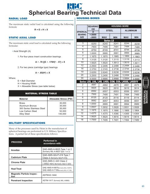
MISALIGNMENT SPECIFICATIONS<br />
The angle of misalignment in a spherical bearing is calculated<br />
somewhat differently from that of the rod end because the<br />
housing is not spherical. There are three different types of<br />
mountings in which these bearings may be used as shown,<br />
and the angle of misalignment is governed by the type of<br />
mounting adopted.<br />
b 1<br />
Sleeve <strong>Bearings</strong><br />
General Information<br />
Sleeve <strong>Bearings</strong><br />
SPHERICAL<br />
BEARINGS<br />
50<br />
Shown below are the common mountings for spherical<br />
bearings and the corresponding formula for calculating the<br />
angle of misalignment.<br />
SPHERICAL<br />
BEARING<br />
PART NUMBER<br />
Reference Letters<br />
B = Bore of ball<br />
C = Chamfer on outer race<br />
D = Head diameter or diameter<br />
of outer race<br />
MAXIMUM MISALIGNMENT<br />
(+/- DEGREES)<br />
LS<br />
3<br />
9.0 16.5 34.5<br />
4<br />
8.0 14.5 29.0<br />
5<br />
9.0 14.0 30.0<br />
6<br />
8.0 12.5 27.0<br />
7<br />
6.5 11.0 25.0<br />
8<br />
7.5 12.5 23.0<br />
10<br />
8.0 12.0 23.0<br />
12<br />
9.0 15.0 27.0<br />
16<br />
6.5 10.0 25.0<br />
19<br />
6.0 8.5 23.5<br />
24<br />
5.0 7.0 23.0<br />
30<br />
5.0 7.0 25.0<br />
LSS, LHA, LHB, LHSS, COM, COS, LHSSE, LHSSVV<br />
2<br />
8.5 13.5 28.0<br />
3<br />
7.0 11.0 29.5<br />
4<br />
9.0 13.0 30.0<br />
5<br />
8.0 12.0 26.0<br />
6<br />
7.5 10.5 23.5<br />
7<br />
6.5 9.5 20.5<br />
8<br />
7.0 10.0 20.0<br />
9<br />
7.5 10.0 20.0<br />
10<br />
7.0 9.0 19.0<br />
12<br />
7.0 9.0 21.0<br />
14<br />
7.0 9.0 16.0<br />
16<br />
7.5 9.5 16.0<br />
LH D<br />
16<br />
19<br />
20<br />
24<br />
28<br />
32<br />
b 1<br />
6.5<br />
6.0<br />
6.0<br />
6.0<br />
6.0<br />
6.0<br />
b 2<br />
8.5<br />
8.0<br />
8.0<br />
8.0<br />
8.0<br />
8.5<br />
b 3<br />
26.0<br />
25.5<br />
23.0<br />
21.0<br />
19.0<br />
19.0<br />
E = Ball diameter<br />
H = Housing width<br />
V = √ (D - 2C) 2 + H 2<br />
W= Ball width<br />
b 1 = SIN -1 W – SIN<br />
V<br />
V<br />
b 2 = SIN -1 W – SIN H<br />
E<br />
E<br />
b 3 = COS -1 B<br />
E<br />
– SIN -1H<br />
E<br />
b 2<br />
b 3<br />
Heim manufactures sleeve bearings in<br />
a wide range of materials and sizes<br />
for industrial, agricultural, and<br />
aerospace applications. Pages 52 and<br />
53 describe two standard series of<br />
self-lubricating bearings that utilize<br />
UNIFLON ® Type E liner material.<br />
This liner meets the requirements of<br />
SAE-AS81820 (formerly MIL-B-81820).<br />
In addition to these standard plain<br />
and flanged series, Heim designs and<br />
manufactures “specials” to meet<br />
specific customer requirements.<br />
Working either from a drawing,<br />
application description or sample<br />
part, Heim also applies UNIFLON ®<br />
liners to customer supplied bearings.<br />
Lined Sleeve <strong>Bearings</strong><br />
(Bushings) - Characteristics<br />
UNIFLON ® liners in sleeve bearings<br />
eliminate the need for lubricating the<br />
bearings during their useful life. The<br />
UNIFLON ® liner is a cost effective<br />
solution to many design problems<br />
where lubrication is impractical or<br />
undesirable. UNIFLON ® lined sleeve<br />
bearings are ideal for applications<br />
where periodic shock loads or vibrations<br />
are encountered. Heim’s new<br />
Type E liner is recommended for<br />
sleeve bearing applications where<br />
temperatures range from -65°F to<br />
350°F. UNIFLON ® liners are highly<br />
resistant to most chemical solvents<br />
encountered in bearing applications.<br />
UNIFLON ® lined sleeve bearings<br />
have a lower coefficient of friction<br />
than metal-to-metal lubricated<br />
bearings. For additional information<br />
on UNIFLON ® liner characteristics see<br />
page 54. You are encouraged to<br />
consult Heim’s engineering department<br />
for recommendations on specific<br />
application problems.<br />
Shaft Data<br />
An important factor influencing the<br />
life of UNIFLON ® lined sleeve bearings<br />
is the condition of the mating<br />
shaft. It is recommended that the<br />
shaft have a surface finish of 8 RMS or<br />
better and a minimum surface hardness<br />
of Rc 40. Commonly preferred<br />
shaft materials are hardened corrosion<br />
resistant steels, hard anodized<br />
aluminum and any metal accepting<br />
hard chrome or nickel plate. The<br />
mating component should be designed<br />
such that there are not sharp<br />
edges which could damage the liner<br />
during assembly of the sleeve bearing.<br />
Cross binding or edge loading on the<br />
bearing should be avoided.<br />
Design Inquiry<br />
To request an engineering design on a<br />
specific application, submit either a<br />
drawing or sketch or submit the<br />
pertinent information. All requests<br />
will receive prompt design engineering<br />
attention and follow-up.<br />
SLEEVE<br />
BEARINGS<br />
51