Rod Ends, Sphericals, Rolling Element Bearings - RBC Bearings
Rod Ends, Sphericals, Rolling Element Bearings - RBC Bearings
Rod Ends, Sphericals, Rolling Element Bearings - RBC Bearings

You also want an ePaper? Increase the reach of your titles
YUMPU automatically turns print PDFs into web optimized ePapers that Google loves.
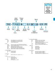
ROD<br />
ENDS<br />
STATIC RADIAL LOAD<br />
The maximum static radial load permissible for a rod end depends<br />
on three factors: race material compressive strength; rod<br />
end head strength; and shank strength. The maximum static<br />
radial load is determined by taking the lowest of the three<br />
following values:<br />
• Race material compressive strengths (R)<br />
• <strong>Rod</strong> end head strength (T)<br />
angle of<br />
H<br />
D<br />
R = E x H x X<br />
insert construction<br />
T = [D - (E + .176 H)] x H x X<br />
cartridge type construction<br />
expressed in radians<br />
• Shank Strength (S)<br />
Where:<br />
male threaded rod end<br />
S = [(root diameter of thread 2 x .78) - (N 2 x .78)] x X<br />
female threaded rod end<br />
S 1 = [(J 2 x .78) - (major diameter of thread 2 x .78)] x X<br />
E = Ball Diameter<br />
H = Housing Width<br />
X = Allowable Stress (see table)<br />
D = Head Diameter<br />
N = Diameter of Drilled Hole in Shank of Male <strong>Rod</strong> <strong>Ends</strong><br />
J = Shank Diameter of Female <strong>Rod</strong> End<br />
Technical Data<br />
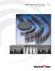
MISALIGNMENT<br />
The angle of misalignment in a rod end is controlled by the outside<br />
diameter of the head. The maximum degree of misalignment is<br />
obtained when the head contacts the side of the fork or clevis in<br />
which it is mounted.<br />
Maximum misalignment is calculated by the following formula.<br />
• <strong>Rod</strong> End Angle (α):<br />
Where:<br />
Material<br />
α = SIN -1 – SIN -1<br />
D = Head diameter or diameter of outer race<br />
H = Housing width<br />
W= Ball width<br />
α<br />
MATERIAL STRESS TABLE<br />
W<br />
D<br />
Allowable Stress (PSI)<br />
Brass 30,000<br />
Aluminum Bronze 35,000<br />
300 Series Stainless Steel 35,000<br />
Low Carbon Steel 52,000<br />
Alloy Steel 140,000<br />
H<br />
D<br />
• Angles of misalignment for series:<br />
HM HF CMHD CFHD<br />
HM C HF C M CR F CR<br />
HM M HF M HMX G HFX G<br />
HME M HFE M BHM BHF<br />
ROD END<br />
SIZE<br />
2<br />
2A<br />
3<br />
4<br />
5<br />
6<br />
7<br />
8<br />
10<br />
12<br />
16<br />
• Angles of misalignment for series:<br />
M M<br />
MD M<br />
ROD END<br />
SIZE<br />
3414<br />
3514<br />
3614<br />
3616<br />
4414<br />
4615<br />
4616<br />
MISALIGNMENT<br />
+/- DEGREES<br />
8.5<br />
7.0<br />
6.5<br />
8.0<br />
7.0<br />
6.0<br />
7.0<br />
6.0<br />
8.0<br />
7.0<br />
8.5<br />
MISALIGNMENT<br />
+/- DEGREES<br />
9.5<br />
8.0<br />
9.5<br />
9.5<br />
10.5<br />
11.0<br />
12.5<br />
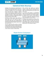
STUDS<br />
Studs are used in combination with Heim rod ends to simplify<br />
mounting. Studs are compatible with the following Heim rod<br />
end series:<br />
M CR<br />
HM C<br />
HM<br />
CMHD<br />
F CR<br />
HF C<br />
HF<br />
CFHD<br />
The stud is designed to accommodate up to ±25° misalignment<br />
in any direction and has a wrench flat to facilitate tightening.<br />
Add letter “Y” to suffix to indicate stud. Example: CMHD10Y<br />
S<br />
T<br />
R<br />
25°<br />
M<br />
right hand<br />
thread only<br />
ROD<br />
ENDS<br />
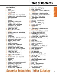
STATIC AXIAL LOAD<br />
• Angles of misalignment for series:<br />
STUD DIMENSIONS<br />
The maximum available axial load for a rod end is determined<br />
by the following formula. This formula does not take into<br />
consideration bending of the shank due to a moment of force.<br />
Also, this formula does not consider the strength of the stake in<br />
cartridge type of construction.<br />
• Axial Strength (A)<br />
Where:<br />
A = .78 [(E + .176 H) 2 – E 2 ] x X<br />
X = Allowable Stress (See Table)<br />
E = Ball Diameter<br />
H = Housing Width<br />
F M<br />
ROD END<br />
SIZE<br />
3414<br />
34714<br />
3416<br />
3514<br />
4414<br />
4519<br />
MISALIGNMENT<br />
+/- DEGREES<br />
9.5<br />
9.5<br />
10.5<br />
9.5<br />
10.5<br />
11.5<br />
TO FIT<br />
ROD END<br />
SIZE<br />
3<br />
4<br />
5<br />
6<br />
7<br />
8<br />
10<br />
12<br />
R<br />
+.010<br />
-.010<br />
.500<br />
.562<br />
.687<br />
.906<br />
1.125<br />
1.125<br />
1.500<br />
1.812<br />
DIMENSIONS IN INCHES<br />
S<br />
M<br />
+.030<br />
-.030<br />
UNF-2A<br />
.969<br />
.1900-32<br />
1.047<br />
.2500-28<br />
1.234<br />
.3125-24<br />
1.540<br />
.3750-24<br />
1.930<br />
.4375-20<br />
2.000<br />
.5000-20<br />
2.500<br />
.6250-18<br />
3.000<br />
.7500-16<br />
28<br />
29