
You also want an ePaper? Increase the reach of your titles
YUMPU automatically turns print PDFs into web optimized ePapers that Google loves.
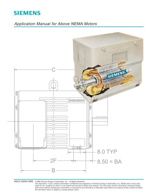
<strong>Application</strong> <strong>Manual</strong> for <strong>Above</strong> <strong>NEMA</strong> <strong>Motor</strong>s<br />
C<br />
2F<br />
B<br />
8.0 TYP<br />
8.50 = BA<br />
ANCD-40000-0996<br />
©1996 Siemens Energy & Automation, Inc. All Rights Reserved<br />
This document, in part, contains information confidential and proprietary to Siemens Energy & Automation, Inc. (SE&A) and is to be used<br />
solely for the purpose for which it is furnished and returned to SE&A upon request. This document and the information contained therein<br />
shall not be altered, reproduced, transmitted, or disclosed to any third party or otherwise used without the express written consent of SE&A.<br />
All information herein is subject to change without notice.
<strong>Application</strong> <strong>Manual</strong> for <strong>Above</strong> <strong>NEMA</strong> <strong>Motor</strong>s<br />
Table of Contents<br />
Section<br />
Part<br />
Page<br />
Date<br />
0<br />
0<br />
Index<br />
9/96<br />
Section 1 Dimension Prints<br />
Section 2 Product Information<br />
Section 3 Electrical & Noise Theories<br />
Section 4 Literature<br />
Section 5 Electrical Information<br />
Section 6 Mechanical Information<br />
Section 7 Accessories<br />
Section 8 Standards<br />
Section 9 Tests<br />
Section 10 Special <strong>Application</strong>s<br />
Section 11 Vertical <strong>Motor</strong>s
<strong>Application</strong> <strong>Manual</strong> for <strong>Above</strong> <strong>NEMA</strong> <strong>Motor</strong>s<br />
Index of Dimension Prints<br />
Section<br />
Part<br />
Page<br />
Date<br />
1<br />
0<br />
Index<br />
9/96<br />
Part 1.1 Horizontal - ODP / WPI Enclosure Page Date<br />
Anti-Friction Bearing<br />
Standard Type IG - 505 / 508 Frames 1 9/96<br />
Custom Type CG - 507 / 509 / 5011 Frames 2 9/96<br />
Custom Type CG - 588 / 5810 Frames - 3600 and 1800 RPM 3 9/96<br />
Custom Type CG - 588 / 5810 Frames - 1200 RPM and Slower 4 9/96<br />
Custom Type CG - 6811 / 6813 Frames - 1800 RPM 5 9/96<br />
Custom Type CG - 6811 / 6813 Frames - 1200 RPM and Slower 6 9/96<br />
Sleeve Bearing<br />
Custom Type CG - 507 / 509 / 5011 Frames 7 9/96<br />
Custom Type CG - 588 / 5810 Frames - 3600 and 1800 RPM 8 9/96<br />
Custom Type CG - 588 / 5810 Frames - 1200 RPM and Slower 8.1 9/96<br />
Custom Type CG - 6811 / 6813 Frames - 3600 RPM 9 9/96<br />
Custom Type CG - 6811 / 6813 Frames - 1800 RPM 10 9/96<br />
Custom Type CG - 6811 / 6813 Frames - 1200 RPM and Slower 11 9/96<br />
Custom Type RG - 809 / 8010 / 8011 / 8012 Frames 12 9/96<br />
Custom Type CG - 1122 / 1124 Frames - 3600 and 1800 RPM 13 9/96<br />
Custom Type CG - 1122 / 1124 Frames - 1200 RPM and Slower 14 9/96<br />
Part 1.2 Horizontal - WPII Enclosure<br />
Anti-Friction Bearing<br />
Custom Type CGII - 507 / 509 / 5011 Frames 2 9/96<br />
Custom Type CGII - 588 / 5810 Frames 3 9/96<br />
Custom Type CGII - 6811 / 6813 Frames - 1800 RPM and Slower 5 9/96<br />
Sleeve Bearing<br />
Custom Type CGII - 507 / 509 / 5011 Frames 6 9/96<br />
Custom Type CGII - 588 / 5810 Frames 7 9/96<br />
Custom Type CGII - 6811 / 6813 Frames - 3600 RPM 8 9/96<br />
Custom Type CGII - 6811 / 6813 Frames - 1800 RPM 9 9/96<br />
Custom Type CGII - 6811 / 6813 Frames - 1200 RPM and Slower 10 9/96<br />
Custom Type FOD - 809 / 8010 / 8011 / 8012 Frames 11 9/96<br />
Custom Type CGII - 1122 / 1124 Frames - 3600 and 1800 RPM 12 9/96<br />
Custom Type CGII - 1122 / 1124 Frames - 1200 RPM and Slower 13 9/96<br />
Part 1.3 Horizontal - TEFC Enclosure<br />
Anti-Friction Bearing<br />
Custom Type CGZ - 449 Frame 1 9/96<br />
Custom Type CGZ - 507 / 509 / 5011 Frames 2 9/96<br />
Custom Type CGZ - 588 / 5810 Frames 3 9/96<br />
Custom Type CGZ - 708 Frame - 1800 RPM and Slower 4 9/96<br />
Custom Type CGZ - 788 Frame - 1800 RPM and Slower 5 9/96<br />
Custom Type CGZ - 880 Frame - 1800 RPM and Slower 6 9/96
<strong>Application</strong> <strong>Manual</strong> for <strong>Above</strong> <strong>NEMA</strong> <strong>Motor</strong>s<br />
Index of Dimension Prints<br />
Section<br />
Part<br />
Page<br />
Date<br />
1<br />
0<br />
Index<br />
9/96<br />
Part 1.3 Horizontal - TEFC Enclosure (Cont'd)<br />
Sleeve Bearing<br />
Custom Type CGZ - 507 / 509 Frames - 3600 RPM 7 9/96<br />
Custom Type CGZ - 507 / 509 / 5011 Frames - 1800 RPM and Slower 8 9/96<br />
Custom Type CGZ - 588 / 5810 Frames 10 9/96<br />
Custom Type CGZ - 708 Frame 11 9/96<br />
Custom Type CGZ - 788 Frame 12 9/96<br />
Part 1.4 Horizontal - Explosion-Proof Enclosure<br />
Anti-Friction Bearing<br />
Custom Type RGZZ - 505 / 507 / 509 Frames 1 9/96<br />
Custom Type CGZZ - 507 / 509 / 5011 Frames 2 9/96<br />
Custom Type AZZ - 30 Frames - Short Shaft - 1800 RPM and Slower 3 9/96<br />
Custom Type AZZ - 30 Frames - Long Shaft - 1200 RPM and Slower 4 9/96<br />
Sleeve Bearing<br />
Custom Type AZZ - 30 Frames 5 9/96<br />
Part 1.5 Vertical - ODP / WPI Enclosure<br />
Custom Type CGV - Solid Shaft - 507 / 509 Frames 1 9/96<br />
Custom Type CGV - Solid Shaft - 588 / 5810 Frames - 3600 and 1800 RPM 2 9/96<br />
Custom Type CGV - Solid Shaft - 588 / 5810 Frames - 1200 RPM and Slower 3 9/96<br />
Custom Type RGV - Solid Shaft - 30 Frames - 1800 RPM and Slower 4 9/96<br />
Custom Type CGHS - Hollow Shaft - 507 / 509 Frames - 1800 RPM and Slower 5 9/96<br />
Custom Type CGHS - Hollow Shaft - 588 / 5810 Frames - 1800 RPM 6 9/96<br />
Custom Type CGHS - Hollow Shaft - 588 / 5810 Frames - 1200 RPM and Slower 7 9/96<br />
Custom Type HSHG - Hollow Shaft - 30 Frames - 1800 RPM and Slower 8 9/96<br />
Part 1.6 Vertical - WPII Enclosure<br />
Custom Type CGIIV - Solid Shaft - 507 / 509 Frames 1 9/96<br />
Custom Type CGIIV - Solid Shaft - 588 / 5810 Frames - 3600 and 1800 RPM 2 9/96<br />
Custom Type FODV - Solid Shaft - 30 Frames - 1800 RPM and Slower 4 9/96<br />
Custom Type CGIIHS - Hollow Shaft - 507 / 509 Frames - 1800 RPM and Slower 5 9/96<br />
Custom Type CGHS - Hollow Shaft - 588 / 5810 Frames - 1800 RPM and Slower 6 9/96<br />
Custom Type HSFOD - Hollow Shaft - 30 Frames - 1800 RPM and Slower 8 9/96
<strong>Application</strong> <strong>Manual</strong> for <strong>Above</strong> <strong>NEMA</strong> <strong>Motor</strong>s<br />
Index of Dimension Prints<br />
Section<br />
Part<br />
Page<br />
Date<br />
1<br />
0<br />
Index<br />
9/96<br />
Part 1.7 Vertical - TEFC Enclosure<br />
Custom Type CGZV - Solid Shaft - 507 / 509 Frames 1 9/96<br />
Custom Type CGZV - Solid Shaft - 588 / 5810 Frames 2 9/96<br />
Custom Type AZV - Solid Shaft - 30 Frames - 1800 RPM and Slower 3 9/96<br />
Custom Type CGZHS - Hollow Shaft - 507 / 509 Frames - 1800 RPM and Slower 4 9/96<br />
Custom Type CGZHS - Hollow Shaft - 588 / 5810 Frames - 1800 RPM and Slower 5 9/96<br />
Custom Type HSZ - Hollow Shaft - 30 Frames - 1800 RPM and Slower 6 9/96<br />
Part 1.8 Vertical - Explosion-Proof Enclosure<br />
Custom Type AZZV - Solid Shaft - 30 Frames - 1800 RPM and Slower 3 9/96
<strong>Application</strong> <strong>Manual</strong> for <strong>Above</strong> <strong>NEMA</strong> <strong>Motor</strong>s<br />
Section<br />
Part<br />
Page<br />
Date<br />
Type IG — Horizontal Standard — Open Drip-Proof — Weather Protected Type I<br />
Anti-Friction Bearing<br />
Frames 505-508<br />
1<br />
1.1<br />
1<br />
9/96<br />
Supersedes Page 10 Date 9/92<br />
C<br />
P<br />
26.25<br />
12.50<br />
2F<br />
B<br />
8.0 TYP<br />
8.50 = BA<br />
N-W<br />
N<br />
ES<br />
U<br />
E<br />
24.50<br />
E<br />
5.00 TYP<br />
Standard Dimensions in Inches<br />
Shaft Frame RPM B C E 2F N N-W P R(2) S(3) U V(1) ES<br />
Approx.<br />
Ship Wt. (Lbs.)<br />
Short 505S 3600 29 40.3 10.0 18 5.5 5.25 28.3 2.275 .625 2.625 5.0 3.5 2900<br />
Short 505S 1800 & Slower 29 41.8 10.0 18 7.0 6.75 28.3 2.88 .875 3.375 6.5 5.0 2900<br />
Short 508S 3600 36 48.8 10.0 25 5.5 5.25 28.3 2.275 .625 2.625 5.0 3.5 3500<br />
Short 508S 1800 & Slower 36 48.8 10.0 25 7.0 6.75 28.3 2.88 .875 3.375 6.5 5.0 3500<br />
Long 505 1800 & Slower 29 44.5 10.0 18 9.75 9.5 28.3 3.436 1.0 4.0 9.25 8.0 2900<br />
Long 508 1800 & Slower 36 52.1 10.0 25 9.75 9.5 28.3 3.436 1.0 4.0 9.25 8.0 3500<br />
Notes<br />
See Section 6 for selection of main terminal box.<br />
R(2)=Bottom of key to opposite side of shaft<br />
S(3)=Width of keyset<br />
V(1)=Length of shaft available for coupling or pully.<br />
Jack screw holes and dowel holes are provided at each foot.<br />
Shims may be necessary under motor feet for direct connection.<br />
3600 RPM machines rotate in one direction only.<br />
1800 RPM and slower machines may rotate in either direction.<br />
Short shaft is for direct connection only.<br />
Long shaft may be either belt drive or direct connect depending on bearing<br />
installed in motor.<br />
Certification<br />
Customer P.O. S.O. Item<br />
HP RPM FR. PH/HZ/Volts<br />
Rotating Facing Shaft Extension CW CCW Either<br />
By<br />
Not for construction, installation or application purposes unless certified.<br />
Date
<strong>Application</strong> <strong>Manual</strong> for <strong>Above</strong> <strong>NEMA</strong> <strong>Motor</strong>s<br />
Type CG — Horizontal Custom — Open Drip Proof — Weather Protected Type I<br />
Anti-Friction Bearing<br />
Frames 507-509-5011<br />
Section<br />
Part<br />
Page<br />
Date<br />
1<br />
1.1<br />
2<br />
9/96<br />
Supersedes Page 11 Date 9/92<br />
C<br />
N-W<br />
N<br />
ES<br />
P<br />
U<br />
26.8<br />
12.50<br />
2F<br />
6.0 TYP<br />
8.50 = BA<br />
E<br />
20.00<br />
E<br />
5.0 TYP<br />
B<br />
Standard Dimensions in Inches<br />
Shaft Frame RPM B C E 2F N N-W P R(2) S(3) U V(1) ES<br />
Approx.<br />
Ship Wt. (Lbs.)<br />
Short 507S 3600 28 44.0 10.0 22 5.5 5.25 28.8 2.275 .625 2.625 5.0 3.5 3000<br />
Short 507S 1800 & Slower 28 45.5 10.0 22 7.0 6.75 28.8 2.88 .875 3.375 6.5 5.0 3100<br />
Short 509S 3600 34 50.0 10.0 28 5.5 5.25 28.8 2.275 .625 2.625 5.0 3.5 3500<br />
Short 509S 1800 & Slower 34 51.5 10.0 28 7.0 6.75 28.8 2.88 .875 3.375 6.5 5.0 3600<br />
Short 5011S 1800 & Slower 42 59.5 10.0 36 7.0 6.75 28.8 2.88 .875 3.375 6.5 5.0 4700<br />
Long 507 1800 & Slower 28 48.3 10.0 22 9.75 9.5 28.8 3.436 1.0 4.0 9.25 8.0 3200<br />
Long 509 1800 & Slower 34 54.3 10.0 28 9.75 9.5 28.8 3.436 1.0 4.0 9.25 8.0 3700<br />
Long 5011 1800 & Slower 42 62.3 10.0 36 9.75 9.5 28.8 3.436 1.0 4.0 9.25 8.0 4700<br />
Notes<br />
See Section 6 for selection of main terminal box.<br />
R(2)=Bottom of key to opposite side of shaft<br />
S(3)=Width of keyset<br />
V(1)=Length of shaft available for coupling or pully.<br />
Jack screw holes and dowel holes are provided at each foot.<br />
Shims may be necessary under motor feet for direct connection.<br />
3600 RPM machines rotate in one direction only.<br />
1800 RPM and slower machines may rotate in either direction.<br />
Short shaft is for direct connection only.<br />
Long shaft may be either belt drive or direct connect depending on bearing<br />
installed in motor.<br />
Certification<br />
Customer P.O. S.O. Item<br />
HP RPM FR. PH/HZ/Volts<br />
Rotating Facing Shaft Extension CW CCW Either<br />
By<br />
Not for construction, installation or application purposes unless certified.<br />
Date
<strong>Application</strong> <strong>Manual</strong> for <strong>Above</strong> <strong>NEMA</strong> <strong>Motor</strong>s<br />
Type CG — Horizontal Custom — Open Drip Proof — Weather Protected Type I<br />
Anti-Friction Bearing<br />
Frames 588-5810 — 3600 and 1800 RPM<br />
Section<br />
Part<br />
Page<br />
Date<br />
1<br />
1.1<br />
3<br />
9/96<br />
Supersedes Page 12 Date 5/96<br />
C<br />
N-W<br />
N<br />
ES<br />
P<br />
U<br />
48.0<br />
14.50<br />
2F<br />
B<br />
10.5 TYP.<br />
10.00 = BA<br />
E<br />
29.0<br />
E<br />
5.50 TYP<br />
Standard Dimensions in Inches<br />
Shaft Frame RPM B C E 2F N N-W P R(2) S(3) U V(1) ES<br />
Approx.<br />
Ship Wt. (Lbs.)<br />
Short 588S 3600 43 55.1 11.5 28 7.0 6.75 53.5 2.45 .75 2.875 6.50 5.0 5400<br />
Short 588S 1800 43 56.4 11.5 28 8.25 8.0 53.5 3.436 1.0 4.0 7.75 6.0 5600<br />
Short 5810S 3600 51 63.1 11.5 36 7.0 6.75 53.5 2.45 .75 2.875 6.5 5.0 6350<br />
Short 5810S 1800 51 64.4 11.5 36 8.25 8.0 53.5 3.436 1.0 4.0 7.75 6.0 6550<br />
Long 588 1800 43 63.0 11.5 28 14.9 14.62 53.5 4.169 1.25 4.875 14.38 13.0 5600<br />
Long 5810 1800 51 71.0 11.5 36 14.9 14.62 53.5 4.169 1.25 4.875 14.38 13.0 6550<br />
Notes<br />
See Section 6 for selection of main terminal box.<br />
R(2)=Bottom of key to opposite side of shaft<br />
S(3)=Width of keyset<br />
V(1)=Length of shaft available for coupling or pully.<br />
Jack screw holes and dowel holes are provided at each foot.<br />
Shims may be necessary under motor feet for direct connection.<br />
3600 RPM machines rotate in one direction only.<br />
1800 RPM and slower machines may rotate in either direction.<br />
Short shaft is for direct connection only.<br />
Long shaft may be either belt drive or direct connect depending on bearing<br />
installed in motor.<br />
Certification<br />
Customer P.O. S.O. Item<br />
HP RPM FR. PH/HZ/Volts<br />
Rotating Facing Shaft Extension CW CCW Either<br />
By<br />
Not for construction, installation or application purposes unless certified.<br />
Date
<strong>Application</strong> <strong>Manual</strong> for <strong>Above</strong> <strong>NEMA</strong> <strong>Motor</strong>s<br />
Type CG — Horizontal Custom — Open Drip Proof — Weather Protected Type I<br />
Anti-Friction Bearing<br />
Frames 588-5810 — 1200 RPM and Slower<br />
Section<br />
Part<br />
Page<br />
Date<br />
1<br />
1.1<br />
4<br />
9/96<br />
Supersedes Page 12.1 Date 3/93<br />
C<br />
N-W<br />
N<br />
ES<br />
P<br />
U<br />
48.0<br />
14.50<br />
2F<br />
B<br />
10.5 Typ<br />
10.00 = BA<br />
E E 5.50<br />
Typ<br />
29.00<br />
Standard Dimensions in Inches<br />
Shaft Frame RPM B C E 2F N N-W P R(2) S(3) U V(1) ES<br />
Approx.<br />
Ship Wt. (Lbs.)<br />
Short 588S 1200 & Slower 43 56.4 11.5 28 8.25 8.0 33.3 3.436 1.0 4.0 7.75 6.0 5400<br />
Short 5810S 1200 & Slower 51 64.4 11.5 36 8.25 8.0 33.3 3.436 1.0 4.0 7.75 6.0 6400<br />
Long 588 1200 & Slower 43 63.0 11.5 28 14.87 14.62 33.3 4.169 1.25 4.875 14.37 13.0 5400<br />
Long 5810 1200 & Slower 51 71.0 11.5 36 14.87 14.62 33.3 4.169 1.25 4.875 14.37 13.0 6400<br />
Notes<br />
See Section 6 for selection of main terminal box.<br />
R(2)=Bottom of key to opposite side of shaft<br />
S(3)=Width of keyset<br />
V(1)=Length of shaft available for coupling or pully.<br />
Jack screw holes and dowel holes are provided at each foot.<br />
Shims may be necessary under motor feet for direct connection.<br />
Machines may rotate in either direction.<br />
Short shaft is for direct connection only.<br />
Long shaft may be either belt drive or direct connect depending on bearing<br />
installed in motor.<br />
Certification<br />
Customer P.O. S.O. Item<br />
HP RPM FR. PH/HZ/Volts<br />
Rotating Facing Shaft Extension CW CCW Either<br />
By<br />
Not for construction, installation or application purposes unless certified.<br />
Date
<strong>Application</strong> <strong>Manual</strong> for <strong>Above</strong> <strong>NEMA</strong> <strong>Motor</strong>s<br />
Type CG — Horizontal Custom — Open Drip Proof — Weather Protected Type I<br />
Anti-Friction Bearing — Direct Connected<br />
Frames 6811-6813 — 1800 RPM<br />
Section<br />
Part<br />
Page<br />
Date<br />
1<br />
1.1<br />
5<br />
9/96<br />
C<br />
N-W<br />
N<br />
ES<br />
P<br />
U<br />
61.7<br />
17.00<br />
2F<br />
B<br />
11.0 TYP<br />
11.50 = BA<br />
E<br />
34.80<br />
E<br />
6.60 TYP<br />
Standard Dimensions in Inches<br />
Shaft Frame RPM B C E 2F N N-W P R(2) S(3) U V(1) ES<br />
Approx.<br />
Ship Wt. (Lbs.)<br />
Short 6811 1800 61 80.6 13.5 50 10.45 9.25 62.3 4.169 1.25 4.875 9.0 8.0 12000<br />
Short 6813 1800 74 93.6 13.5 63 10.45 9.25 62.3 4.169 1.25 4.875 9.0 8.0 14700<br />
Notes<br />
See Section 6 for selection of main terminal box.<br />
R(2)=Bottom of key to opposite side of shaft<br />
S(3)=Width of keyset<br />
V(1)=Length of shaft available for coupling or pully.<br />
Jack screw holes and dowel holes are provided at each foot.<br />
Shims may be necessary under motor feet for direct connection.<br />
Machines may rotate in either direction.<br />
Long shaft may be either belt drive or direct connect depending on bearing<br />
installed in motor.<br />
Certification<br />
Customer P.O. S.O. Item<br />
HP RPM FR. PH/HZ/Volts<br />
Rotating Facing Shaft Extension CW CCW Either<br />
By<br />
Not for construction, installation or application purposes unless certified.<br />
Date
<strong>Application</strong> <strong>Manual</strong> for <strong>Above</strong> <strong>NEMA</strong> <strong>Motor</strong>s<br />
Type CG — Horizontal Custom — Open Drip Proof — Weather Protected Type I<br />
Anti-Friction Bearing — Direct Connected<br />
Frames 6811-6813 — 1200 RPM and Slower<br />
Section<br />
Part<br />
Page<br />
Date<br />
1<br />
1.1<br />
6<br />
9/96<br />
C<br />
N-W<br />
N<br />
ES<br />
P<br />
U<br />
61.7<br />
17.0<br />
2F<br />
B<br />
11.0 TYP<br />
11.50 = BA<br />
E<br />
40.0<br />
E<br />
6.6 TYP<br />
Standard Dimensions in Inches<br />
Shaft Frame RPM B C E 2F N N-W P R(2) S(3) U V(1) ES<br />
Approx.<br />
Ship Wt. (Lbs.)<br />
Short 6811 1200 & Slower 61 80.6 13.5 50 10.45 9.25 43.0 4.676 1.25 5.375 9.0 8.0 11800<br />
Short 6813 1200 & Slower 74 93.6 13.5 63 10.45 9.25 43.0 4.676 1.25 5.375 9.0 8.0 14200<br />
Notes<br />
See Section 6 for selection of main terminal box.<br />
R(2)=Bottom of key to opposite side of shaft<br />
S(3)=Width of keyset<br />
V(1)=Length of shaft available for coupling or pully.<br />
Jack screw holes and dowel holes are provided at each foot.<br />
Shims may be necessary under motor feet for direct connection.<br />
Machines may rotate in either direction.<br />
Certification<br />
Customer P.O. S.O. Item<br />
HP RPM FR. PH/HZ/Volts<br />
Rotating Facing Shaft Extension CW CCW Either<br />
By<br />
Not for construction, installation or application purposes unless certified.<br />
Date
<strong>Application</strong> <strong>Manual</strong> for <strong>Above</strong> <strong>NEMA</strong> <strong>Motor</strong>s<br />
Section<br />
Part<br />
Page<br />
Date<br />
1<br />
1.1<br />
7<br />
9/96<br />
Supersedes Page 21 Date 9/92<br />
Type CG — Horizontal Custom — Drip Proof — Weather Protected Type I<br />
Sleeve Bearing — Direct Connected<br />
Frames 507-509-5011<br />
C*<br />
P<br />
26.8<br />
12.50<br />
2F<br />
B<br />
6.0 TYP<br />
8.50 = BA*<br />
N-W<br />
N<br />
ES<br />
E<br />
25.00<br />
E<br />
5.0 TYP.<br />
U<br />
Standard Dimensions in Inches<br />
Shaft Frame RPM B C E 2F N N-W P R(2) S(3) U V(1) ES<br />
Approx.<br />
Ship Wt. (Lbs.)<br />
Short 507S 3600 28 44.0 10.0 22 5.5 5.25 28.8 2.275 .625 2.625 5.0 3.5 3000<br />
Short 507S 1800 & Slower 28 45.5 10.0 22 7.0 6.75 28.8 2.880 .875 3.375 6.5 5.0 3100<br />
Short 509S 3600 34 50.0 10.0 28 5.5 5.25 28.8 2.275 .625 2.625 5.0 3.5 3500<br />
Short 509S 1800 & Slower 34 51.5 10.0 28 7.0 6.75 28.8 2.880 .875 3.375 6.5 5.0 3600<br />
Short 5011S 1800 & Slower 42 59.5 10.0 36 7.0 6.75 28.8 2.880 .875 3.375 6.5 5.0 4700<br />
Notes<br />
See Section 6 for selection of main terminal box.<br />
R(2)=Bottom of key to opposite side of shaft.<br />
S(3)=Width of keyset.<br />
V(1)=Length of shaft available for coupling or pully.<br />
Jack screw holes and dowel holes are provided at<br />
each foot.<br />
Shims may be necessary under motor feet for direct<br />
connection.<br />
3600 RPM machines rotate in one direction only.<br />
1800 RPM and slower may rotate in either direction.<br />
* On machines equipped with provisions for or with<br />
proximity type probes the BA and C dimensions<br />
will change. Consult factory for specific<br />
dimensions.<br />
Rotor end float = 0.5"<br />
End float of LEF coupling = 0.19"<br />
Lubrication<br />
3600 RPM 1800 RPM & Slower<br />
140-160 SUS @ 100˚ F 290-350 SUS @ 100˚ F<br />
0.8 qt. capacity 0.8 qt. capacity<br />
Certification<br />
Customer P.O. S.O. Item<br />
HP RPM FR. PH/HZ/Volts<br />
Rotating Facing Shaft Extension CW CCW Either<br />
By<br />
Not for construction, installation or application purposes unless certified.<br />
Date
<strong>Application</strong> <strong>Manual</strong> for <strong>Above</strong> <strong>NEMA</strong> <strong>Motor</strong>s<br />
Section<br />
Part<br />
Page<br />
Date<br />
1<br />
1.1<br />
8<br />
9/96<br />
Supersedes Page 22 Date 9/92<br />
Type CG — Horizontal Custom — Open Drip Proof — Weather Protected Type I<br />
Sleeve Bearing — Direct Connected<br />
Frames 588-5810 — 3600 and 1800 RPM<br />
C*<br />
N-W<br />
N<br />
ES<br />
P<br />
U<br />
48.0<br />
14.50<br />
2F<br />
B<br />
10.5 TYP<br />
10.00 = BA*<br />
E E<br />
29.00<br />
5.50 TYP<br />
Standard Dimensions in Inches<br />
Shaft Frame RPM B C E 2F N N-W P R(2) S(3) U V(1) ES<br />
Approx.<br />
Ship Wt. (Lbs.)<br />
Short 588S 3600 43 55.0 11.5 28 7.13 6.75 53.5 2.88 .875 3.375 6.5 5.0 5400<br />
Short 588S 1800 43 56.2 11.5 28 8.38 8.0 53.5 3.436 1.0 4.0 7.75 6.0 5600<br />
Short 5810S 3600 51 63.0 11.5 36 7.13 6.75 53.5 2.88 .875 3.375 6.5 5.0 6500<br />
Short 5810S 1800 51 64.2 11.5 36 8.83 8.0 53.5 3.436 1.0 4.0 7.75 6.0 6600<br />
Notes<br />
See Section 6 for selection of main terminal box.<br />
R(2)=Bottom of key to opposite side of shaft.<br />
S(3)=Width of keyset.<br />
V(1)=Length of shaft available for coupling or pully.<br />
Jack screw holes and dowel holes are provided at<br />
each foot.<br />
Shims may be necessary under motor feet for direct<br />
connection.<br />
3600 RPM machines rotate in one direction only.<br />
1800 RPM may rotate in either direction.<br />
* On machines equipped with provisions for or with<br />
proximity type probes the BA and C dimensions<br />
will change. Consult factory for specific<br />
dimensions.<br />
Rotor end float = 0.5"<br />
End float of LEF coupling = 0.19"<br />
Lubrication<br />
3600 RPM 1800 RPM<br />
140-160 SUS @ 100˚ F 290-350 SUS @ 100˚ F<br />
3.5 qt. capacity 3.5 qt. capacity<br />
Certification<br />
Customer P.O. S.O. Item<br />
HP RPM FR. PH/HZ/Volts<br />
Rotating Facing Shaft Extension CW CCW Either<br />
By<br />
Not for construction, installation or application purposes unless certified.<br />
Date
<strong>Application</strong> <strong>Manual</strong> for <strong>Above</strong> <strong>NEMA</strong> <strong>Motor</strong>s<br />
Section<br />
Part<br />
Page<br />
Date<br />
1<br />
1.1<br />
8.1<br />
9/96<br />
Supersedes Page 22 Date 9/92<br />
Type CG — Horizontal Custom — Open Drip Proof — Weather Protected Type I<br />
Sleeve Bearing — Direct Connected<br />
Frames 588-5810 — 1200 RPM and Slower<br />
C*<br />
N-W<br />
N<br />
ES<br />
P<br />
U<br />
48.0<br />
14.50<br />
2F<br />
10.5 TYP<br />
10.00 = BA*<br />
E<br />
E<br />
5.50<br />
TYP<br />
B<br />
29.0<br />
Standard Dimensions in Inches<br />
Shaft Frame RPM B C E 2F N N-W P R(2) S(3) U V(1) ES<br />
Approx.<br />
Ship Wt. (Lbs.)<br />
Short 588S 1200 & Slower 43 57.8 11.5 28 8.38 8.0 33.3 3.436 1.0 4.0 7.75 6.0 5100<br />
Short 5810S 1200 & Slower 51 65.8 11.5 36 8.83 8.0 33.3 3.436 1.0 4.0 7.75 6.0 6000<br />
Notes<br />
See Section 6 for selection of main terminal box.<br />
R(2)=Bottom of key to opposite side of shaft.<br />
S(3)=Width of keyset.<br />
V(1)=Length of shaft available for coupling or pully.<br />
Jack screw holes and dowel holes are provided at<br />
each foot.<br />
Shims may be necessary under motor feet for direct<br />
connection.<br />
Machines may rotate in either direction.<br />
* On machines equipped with provisions for or with<br />
proximity type probes the BA and C dimensions<br />
will change. Consult factory for specific<br />
dimensions.<br />
Rotor end float = 0.5"<br />
End float of LEF coupling = 0.19"<br />
Lubrication<br />
290-350 SUS @ 100˚ F<br />
3.5 qt. capacity<br />
Certification<br />
Customer P.O. S.O. Item<br />
HP RPM FR. PH/HZ/Volts<br />
Rotating Facing Shaft Extension CW CCW Either<br />
By<br />
Not for construction, installation or application purposes unless certified.<br />
Date
<strong>Application</strong> <strong>Manual</strong> for <strong>Above</strong> <strong>NEMA</strong> <strong>Motor</strong>s<br />
Section<br />
Part<br />
Page<br />
Date<br />
1<br />
1.1<br />
9<br />
9/96<br />
Type CG — Horizontal Custom — Open Drip Proof — Weather Protected Type I<br />
Sleeve Bearing — Direct Connected<br />
Frames 6811-6813 — 3600 RPM<br />
C*<br />
P<br />
61.7<br />
17.00<br />
2F<br />
B<br />
12.5 TYP<br />
11.50 = BA*<br />
N-W<br />
N<br />
ES<br />
E<br />
34.80<br />
E<br />
6.60 TYP<br />
U<br />
Standard Dimensions in Inches<br />
Shaft Frame RPM B C E 2F N N-W P R(2) S(3) U V(1) ES<br />
Approx.<br />
Ship Wt. (Lbs.)<br />
Short 6811 3600 61 79.0 13.5 50 7.97 7.0 62.3 3.007 .875 3.50 6.75 5.5 11200<br />
Short 6813 3600 74 92.0 13.5 63 7.97 7.0 62.3 3.007 .875 3.50 6.75 5.5 13900<br />
Notes<br />
See Section 6 for selection of main terminal box.<br />
R(2)=Bottom of key to opposite side of shaft.<br />
S(3)=Width of keyset.<br />
V(1)=Length of shaft available for coupling or pully.<br />
Jack screw holes and dowel holes are provided at each foot.<br />
Shims may be necessary under motor feet for direct<br />
connection.<br />
3600 RPM machines rotate in one direction only.<br />
* On machines equipped with provisions for or with proximity<br />
type probes the BA and C dimensions will change. Consult<br />
factory for specific dimensions.<br />
Rotor end float = 0.5"<br />
End float of LEF coupling = 0.19"<br />
Lubrication<br />
3600 RPM<br />
140-160 SUS @ 100˚ F<br />
3 qt. capacity<br />
Certification<br />
Customer P.O. S.O. Item<br />
HP RPM FR. PH/HZ/Volts<br />
Rotating Facing Shaft Extension CW CCW Either<br />
By<br />
Not for construction, installation or application purposes unless certified.<br />
Date
<strong>Application</strong> <strong>Manual</strong> for <strong>Above</strong> <strong>NEMA</strong> <strong>Motor</strong>s<br />
Section<br />
Part<br />
Page<br />
Date<br />
1<br />
1.1<br />
10<br />
9/96<br />
Type CG — Horizontal Custom — Open Drip Proof — Weather Protected Type I<br />
Sleeve Bearing — Direct Connected<br />
Frames 6811-6813 — 1800 RPM<br />
C*<br />
P<br />
61.7<br />
17.00<br />
2F<br />
B<br />
12.5 TYP<br />
11.50 = BA*<br />
N-W<br />
N<br />
ES<br />
E<br />
34.80<br />
E<br />
6.60 TYP<br />
U<br />
Standard Dimensions in Inches<br />
Shaft Frame RPM B C E 2F N N-W P R(2) S(3) U V(1) ES<br />
Approx.<br />
Ship Wt. (Lbs.)<br />
Short 6811 1800 61 81.3 13.5 50 10.22 9.25 62.3 4.169 1.25 4.875 9.0 8.0 12000<br />
Short 6813 1800 74 94.5 13.5 63 10.22 9.25 62.3 4.169 1.25 4.875 9.0 8.0 14700<br />
Notes<br />
See Section 6 for selection of main terminal box.<br />
R(2)=Bottom of key to opposite side of shaft.<br />
S(3)=Width of keyset.<br />
V(1)=Length of shaft available for coupling or pully.<br />
Jack screw holes and dowel holes are provided at each foot.<br />
Shims may be necessary under motor feet for direct<br />
connection.<br />
1800 RPM machines may rotate in either direction.<br />
* On machines equipped with provisions for or with proximity<br />
type probes the BA and C dimensions will change. Consult<br />
factory for specific dimensions.<br />
Rotor end float = 0.5"<br />
End float of LEF coupling = 0.19"<br />
Lubrication<br />
1800 RPM<br />
290-350 SUS @ 100˚ F<br />
3.0 qt. capacity<br />
Certification<br />
Customer P.O. S.O. Item<br />
HP RPM FR. PH/HZ/Volts<br />
Rotating Facing Shaft Extension CW CCW Either<br />
By<br />
Not for construction, installation or application purposes unless certified.<br />
Date
<strong>Application</strong> <strong>Manual</strong> for <strong>Above</strong> <strong>NEMA</strong> <strong>Motor</strong>s<br />
Section<br />
Part<br />
Page<br />
Date<br />
1<br />
1.1<br />
11<br />
9/96<br />
Type CG — Horizontal Custom — Open Drip Proof — Weather Protected Type I<br />
Sleeve Bearing — Direct Connected<br />
Frames 6811-6813 — 1200 RPM and Slower<br />
C*<br />
N-W<br />
N<br />
ES<br />
P<br />
U<br />
61.7<br />
17.0<br />
11.0 TYP<br />
6.6 TYP<br />
2F<br />
11.50 = BA*<br />
E<br />
40.0<br />
E<br />
B<br />
Standard Dimensions in Inches<br />
Shaft Frame RPM B C E 2F N N-W P R(2) S(3) U V(1) ES<br />
Approx.<br />
Ship Wt. (Lbs.)<br />
Short 6811 1200 & Slower 61 81.3 13.5 50 10.22 9.25 43.0 4.676 1.25 5.375 9.0 8.0 11800<br />
Short 6813 1200 & Slower 74 94.3 13.5 63 10.22 9.25 43.0 4.676 1.25 5.375 9.0 8.0 14200<br />
Notes<br />
See Section 6 for selection of main terminal box.<br />
R(2)=Bottom of key to opposite side of shaft.<br />
S(3)=Width of keyset.<br />
V(1)=Length of shaft available for coupling or pully.<br />
Jack screw holes and dowel holes are provided at each foot.<br />
Shims may be necessary under motor feet for direct<br />
connection.<br />
Machines may rotate in either direction.<br />
* On machines equipped with provisions for or with proximity<br />
type probes the BA and C dimensions will change. Consult<br />
factory for specific dimensions.<br />
Rotor end float = 0.5"<br />
End float of LEF coupling = 0.19"<br />
Lubrication<br />
290-350 SUS @ 100˚ F<br />
3.0 qt. capacity<br />
Certification<br />
Customer P.O. S.O. Item<br />
HP RPM FR. PH/HZ/Volts<br />
Rotating Facing Shaft Extension CW CCW Either<br />
By<br />
Not for construction, installation or application purposes unless certified.<br />
Date
<strong>Application</strong> <strong>Manual</strong> for <strong>Above</strong> <strong>NEMA</strong> <strong>Motor</strong>s<br />
Type RG — Horizontal Custom — Open Drip Proof — Weather Protected Type I<br />
Sleeve Bearing — Direct Connected<br />
Frames 809-8012<br />
Section<br />
Part<br />
Page<br />
Date<br />
1<br />
1.1<br />
12<br />
9/96<br />
Supersedes Page 19 Date 9/92<br />
C*<br />
N-W<br />
N<br />
ES<br />
P<br />
U<br />
86.5<br />
20.00<br />
20.1 TYP<br />
2F<br />
B<br />
15.75 = BA*<br />
E E<br />
40.0<br />
8.00 TYP<br />
Standard Dimensions in Inches<br />
Shaft Frame RPM B C E 2F N N-W P R(2) S(3) U V(1) ES<br />
Approx.<br />
Ship Wt. (Lbs.)<br />
Short 809 3600 69 90.5 17.0 50 10.0 9.25 50.0 4.803 1.25 5.5 8.85 7.0 15000<br />
Short 809 1800 & Slower 69 92.25 17.0 50 11.75 11.0 50.0 5.662 1.5 6.5 10.6 9.0 16000<br />
Short 8010 3600 75 96.0 17.0 56 10.0 9.25 50.0 4.803 1.25 5.5 8.85 7.0 16000<br />
Short 8010 1800 & Slower 75 97.75 17.0 56 11.75 11.0 50.0 5.662 1.5 6.5 10.6 9.0 17000<br />
Short 8011 3600 82 103.0 17.0 63 10.0 9.25 50.0 4.803 1.25 5..5 8.85 7.0 17000<br />
Short 8011 1800 & Slower 82 104.75 17.0 63 11.75 11.0 50.0 5.662 1.5 6.5 10.6 9.0 18000<br />
Short 8012 3600 90 111.5 17.0 71 10.0 9.25 50.0 4.803 1.25 5.5 8.85 7.0 19000<br />
Short 8012 1800 & Slower 90 113.25 17.0 71 11.75 11.0 50.0 5.662 1.5 6.5 10.6 9.0 20000<br />
Notes<br />
See Section 6 for selection of main terminal box.<br />
R(2)=Bottom of key to opposite side of shaft.<br />
S(3)=Width of keyset.<br />
V(1)=Length of shaft available for coupling or pully.<br />
Jack screw holes and dowel holes are provided at<br />
each foot.<br />
Shims may be necessary under motor feet for direct<br />
connection.<br />
3600 RPM machines rotate in one direction only.<br />
1800 RPM and slower may rotate in either direction.<br />
* On machines equipped with provisions for or with<br />
proximity type probes the BA and C dimensions<br />
will change. Consult factory for specific<br />
dimensions.<br />
Rotor end float = 0.5"<br />
End float of LEF coupling = 0.19"<br />
Lubrication<br />
3600 RPM 1800 RPM & Slower<br />
140-160 SUS @ 100˚ F 290-350 SUS @ 100˚ F<br />
10.4 qt. capacity 10.4 qt. capacity<br />
Certification<br />
Customer P.O. S.O. Item<br />
HP RPM FR. PH/HZ/Volts<br />
Rotating Facing Shaft Extension CW CCW Either<br />
By<br />
Not for construction, installation or application purposes unless certified.<br />
Date
<strong>Application</strong> <strong>Manual</strong> for <strong>Above</strong> <strong>NEMA</strong> <strong>Motor</strong>s<br />
Type CG — Horizontal Custom — Open Drip Proof — Weather Protected Type I<br />
Sleeve Bearing — Direct Connected<br />
Frames 1122-1124 — 3600 and 1800 RPM<br />
Section<br />
Part<br />
Page<br />
Date<br />
1<br />
1.1<br />
13<br />
9/96<br />
C*<br />
N-W<br />
N<br />
ES<br />
P<br />
U<br />
96.5<br />
28.00<br />
2F<br />
18.0 TYP<br />
BA*<br />
E E<br />
B<br />
51.2<br />
5.0 TYP<br />
Standard Dimensions in Inches<br />
Shaft Frame RPM B C E 2F N N-W P R(2) S(3) U V(1) ES<br />
Approx.<br />
Ship Wt. (Lbs.)<br />
Short 1122 3600 88 23.25 76 65.0 28500<br />
Short 1122 1800 88 23.25 76 65.0 29500<br />
Short 1124 3600 96 23.25 84 65.0 30500<br />
Short 1124 1800 96 23.25 84 65.0 31500<br />
Notes<br />
See Section 6 for selection of main terminal box.<br />
V(1)=Length of shaft available for coupling or pully.<br />
R(2)=Bottom of key to opposite side of shaft.<br />
S(3)=Width of keyset.<br />
Jack screw holes and dowel holes are provided at<br />
each foot.<br />
Shims may be necessary under motor feet for direct<br />
connection.<br />
Machines rotate in one direction only.<br />
* On machines equipped with provisions for or with<br />
proximity type probes the BA and C dimensions<br />
will change. Consult factory for specific<br />
dimensions.<br />
Rotor end float = 0.5"<br />
End float of LEF coupling = 0.19"<br />
Lubrication<br />
3600 RPM 1800 RPM<br />
140-160 SUS @ 100˚ F 290-350 SUS @ 100˚ F<br />
8.4 qt. capacity 8.4 qt. capacity<br />
Certification<br />
Customer P.O. S.O. Item<br />
HP RPM FR. PH/HZ/Volts<br />
Rotating Facing Shaft Extension CW CCW Either<br />
By<br />
Not for construction, installation or application purposes unless certified.<br />
Date
<strong>Application</strong> <strong>Manual</strong> for <strong>Above</strong> <strong>NEMA</strong> <strong>Motor</strong>s<br />
Type CG — Horizontal Custom — Open Drip Proof — Weather Protected Type I<br />
Sleeve Bearing — Direct Connected<br />
Frames 1122-1124 — 1200 RPM and Slower<br />
Section<br />
Part<br />
Page<br />
Date<br />
1<br />
1.1<br />
14<br />
9/96<br />
C*<br />
N-W<br />
N<br />
ES<br />
P<br />
U<br />
96.5<br />
28.00<br />
2F<br />
18.0 TYP<br />
BA*<br />
E E<br />
B<br />
51.2<br />
5.0 TYP<br />
Standard Dimensions in Inches<br />
Shaft Frame RPM B C E 2F N N-W P R(2) S(3) U V(1) ES<br />
Approx.<br />
Ship Wt. (Lbs.)<br />
Short 1122 1200 & Slower 88 23.25 76 65.0 29500<br />
Short 1124 1200 & Slower 96 23.25 84 65.0 31500<br />
Notes<br />
See Section 6 for selection of main terminal box.<br />
R(2)=Bottom of key to opposite side of shaft<br />
S(3)=Width of keyset<br />
V(1)=Length of shaft available for coupling or pully.<br />
Jack screw holes and dowel holes are provided at each foot.<br />
Shims may be necessary under motor feet for direct<br />
connection.<br />
Machines rotate in one direction only.<br />
* On machines equipped with provisions for or with proximity<br />
type probes the BA and C dimensions will change.<br />
Consult factory for specific dimensions.<br />
Rotor end float = 0.5"<br />
End float of LEF coupling = 0.19"<br />
Lubrication<br />
290-350 SUS @ 100˚ F<br />
13.6 qt. capacity<br />
Certification<br />
Customer P.O. S.O. Item<br />
HP RPM FR. PH/HZ/Volts<br />
Rotating Facing Shaft Extension CW CCW Either<br />
By<br />
Not for construction, installation or application purposes unless certified.<br />
Date
<strong>Application</strong> <strong>Manual</strong> for <strong>Above</strong> <strong>NEMA</strong> <strong>Motor</strong>s<br />
Type CGII — Horizontal Custom — Weather Protected Type II<br />
Anti-Friction Bearing<br />
Frames 507-509-5011<br />
Section<br />
Part<br />
Page<br />
Date<br />
1<br />
1.2<br />
2<br />
9/96<br />
Supersedes Page 7 Date 9/92<br />
C<br />
P<br />
43.2<br />
12.50<br />
2F<br />
B<br />
8.50<br />
6.0 TYP<br />
N-W<br />
N<br />
ES<br />
U<br />
E<br />
25.00<br />
E<br />
5.0 TYP<br />
Standard Dimensions in Inches<br />
Shaft Frame RPM B C E 2F N N-W P R(2) S(3) U V(1) ES<br />
Approx.<br />
Ship Wt. (Lbs.)<br />
Short 507S 3600 28 44.7 10.0 22 5.5 5.25 44.0 2.275 .625 2.625 5.0 3.5 3500<br />
Short 507S 1800 & Slower 28 46.2 10.0 22 7.0 6.75 44.0 2.88 .875 3.375 6.5 5.0 3500<br />
Short 509S 3600 34 50.7 10.0 28 5.5 5.25 44.0 2.275 .625 2.625 5.0 3.5 4000<br />
Short 509S 1800 & Slower 34 52.2 10.0 28 7.0 6.75 44.0 2.88 .875 3.375 6.5 5.0 4000<br />
Short 5011S 1800 & Slower 42 60.2 10.0 36 7.0 6.75 44.0 2.88 .875 3.375 6.5 5.0 5200<br />
Long 507 1800 & Slower 28 48.9 10.0 22 9.75 9.5 44.0 3.436 1.0 4.0 9.25 8.0 3500<br />
Long 509 1800 & Slower 34 54.9 10.0 28 9.75 9.5 44.0 3.436 1.0 4.0 9.25 8.0 4000<br />
Long 5011 1800 & Slower 42 62.9 10.0 36 9.75 9.5 44.0 3.436 1.0 4.0 9.25 8.0 5200<br />
Notes<br />
See Section 6 for selection of main terminal box.<br />
R(2)=Bottom of key to opposite side of shaft<br />
S(3)=Width of keyset<br />
V(1)=Length of shaft available for coupling or pully.<br />
Jack screw holes and dowel holes are provided at each foot.<br />
Shims may be necessary under motor feet for direct connection.<br />
3600 RPM machines rotate in one direction only.<br />
1800 RPM and slower machines may rotate in either direction.<br />
Short shaft is for direct connection only.<br />
Long shaft may be either belt drive or direct connect depending on bearing<br />
installed in motor.<br />
Certification<br />
Customer P.O. S.O. Item<br />
HP RPM FR. PH/HZ/Volts<br />
Rotating Facing Shaft Extension CW CCW Either<br />
By<br />
Not for construction, installation or application purposes unless certified.<br />
Date
<strong>Application</strong> <strong>Manual</strong> for <strong>Above</strong> <strong>NEMA</strong> <strong>Motor</strong>s<br />
Type CGII — Horizontal Custom — Weather Protected Type II<br />
Anti-Friction Bearing<br />
Frames 588-5810<br />
Section<br />
Part<br />
Page<br />
Date<br />
1<br />
1.2<br />
3<br />
9/96<br />
Supersedes Page 8 Date 5/96<br />
C<br />
N-W<br />
N<br />
ES<br />
P<br />
U<br />
52.5<br />
14.50<br />
2F<br />
B<br />
10.5 TYP<br />
10.0 = BA<br />
E<br />
29.00<br />
E<br />
5.50 TYP<br />
Standard Dimensions in Inches<br />
Shaft Frame RPM B C E 2F N N-W P R(2) S(3) U V(1) ES<br />
Approx.<br />
Ship Wt. (Lbs.)<br />
Short 588S 3600 43 55.1 11.5 28 7.0 6.75 53.5 2.45 .875 2.85 6.5 5.0 5300<br />
Short 588S 1800 & Slower 43 56.4 11.5 28 8.25 8.0 53.5 3.436 1.0 4.0 7.75 6.0 5600<br />
Short 5810S 3600 51 63.1 11.5 36 7.0 6.75 53.5 2.45 .875 2.85 6.5 5.0 6500<br />
Short 5810S 1800 & Slower 51 64.4 11.5 36 8.25 8.0 53.5 3.436 1.0 4.0 7.75 6.0 6800<br />
Long 588 1800 & Slower 43 63.0 11.5 28 14.9 14.62 53.5 4.169 1.25 4.875 14.38 13.0 5600<br />
Long 5810 1800 & Slower 51 71.0 11.5 36 14.9 14.62 53.5 4.169 1.25 4.875 14.38 13.0 6800<br />
Notes<br />
See Section 6 for selection of main terminal box.<br />
R(2)=Bottom of key to opposite side of shaft<br />
S(3)=Width of keyset<br />
V(1)=Length of shaft available for coupling or pully.<br />
Jack screw holes and dowel holes are provided at each foot.<br />
Shims may be necessary under motor feet for direct connection.<br />
3600 RPM machines rotate in one direction only.<br />
1800 RPM and slower machines may rotate in either direction.<br />
Short shaft is for direct connection only.<br />
Long shaft may be either belt drive or direct connect depending on bearing<br />
installed in motor.<br />
Certification<br />
Customer P.O. S.O. Item<br />
HP RPM FR. PH/HZ/Volts<br />
Rotating Facing Shaft Extension CW CCW Either<br />
By<br />
Not for construction, installation or application purposes unless certified.<br />
Date
<strong>Application</strong> <strong>Manual</strong> for <strong>Above</strong> <strong>NEMA</strong> <strong>Motor</strong>s<br />
Type CGII — Horizontal Custom — Weather Protected Type II<br />
Anti-Friction Bearing — Direct Connected<br />
Frames 6811-6813 — 1800 RPM and Slower<br />
Section<br />
Part<br />
Page<br />
Date<br />
1<br />
1.2<br />
5<br />
9/96<br />
Supersedes Page 8 Date 5/96<br />
C<br />
N-W<br />
N<br />
ES<br />
P<br />
U<br />
61.7<br />
17.00<br />
2F<br />
B<br />
11.0 TYP<br />
11.50 = BA<br />
E<br />
34.80<br />
E<br />
6.60 TYP<br />
Standard Dimensions in Inches<br />
Shaft Frame RPM B C E 2F N N-W P R(2) S(3) U V(1) ES<br />
Approx.<br />
Ship Wt. (Lbs.)<br />
Short 6811 1800 61 80.6 13.5 50 10.45 9.25 62.3 4.169 1.25 4.875 9.0 8.0 12000<br />
Short 6811 1200 & Slower 61 80.6 13.5 50 10.45 9.25 62.3 4.676 1.25 5.375 9.0 8.0 12000<br />
Short 6813 1800 74 93.6 13.5 63 10.45 9.25 62.3 4.169 1.25 4.875 9.0 8.0 14700<br />
Short 6813 1200 & Slower 74 93.6 13.5 63 10.45 9.25 62.3 4.676 1.25 5.375 9.0 8.0 14700<br />
Notes<br />
See Section 6 for selection of main terminal box.<br />
R(2)=Bottom of key to opposite side of shaft<br />
S(3)=Width of keyset<br />
V(1)=Length of shaft available for coupling or pully.<br />
Jack screw holes and dowel holes are provided at each foot.<br />
Shims may be necessary under motor feet for direct connection.<br />
Machines may rotate in either direction.<br />
Certification<br />
Customer P.O. S.O. Item<br />
HP RPM FR. PH/HZ/Volts<br />
Rotating Facing Shaft Extension CW CCW Either<br />
By<br />
Not for construction, installation or application purposes unless certified.<br />
Date
<strong>Application</strong> <strong>Manual</strong> for <strong>Above</strong> <strong>NEMA</strong> <strong>Motor</strong>s<br />
Type CGII — Horizontal Custom — Weather Protected Type II<br />
Sleeve Bearing — Direct Connected<br />
Frames 507-509-5011<br />
Section<br />
Part<br />
Page<br />
Date<br />
1<br />
1.2<br />
6<br />
9/96<br />
Supersedes Page 15 Date 9/92<br />
C*<br />
N-W<br />
N<br />
ES<br />
P<br />
U<br />
43.2<br />
12.50<br />
2F<br />
B<br />
6.0 TYP<br />
8.5 = BA*<br />
E E<br />
25.00<br />
5.0 TYP<br />
Standard Dimensions in Inches<br />
Shaft Frame RPM B C E 2F N N-W P R(2) S(3) U V(1) ES<br />
Approx.<br />
Ship Wt. (Lbs.)<br />
Short 507S 3600 28 44.7 10.0 22 5.5 5.25 44.0 2.275 .625 2.625 5.0 3.5 3500<br />
Short 507S 1800 & Slower 28 46.2 10.0 22 7.0 6.75 44.0 2.88 .875 3.375 6.5 5.0 3500<br />
Short 509S 3600 34 50.7 10.0 28 5.5 5.25 44.0 2.275 .625 2.625 5.0 3.5 4000<br />
Short 509S 1800 & Slower 34 52.2 10.0 28 7.0 6.75 44.0 2.88 .875 3.375 6.5 5.0 4000<br />
Short 5011S 1800 & Slower 42 60.2 10.0 36 7.0 6.75 44.0 2.88 .875 3.375 6.5 5.0 5200<br />
Notes<br />
See Section 6 for selection of main terminal box.<br />
R(2)=Bottom of key to opposite side of shaft<br />
S(3)=Width of keyset<br />
V(1)=Length of shaft available for coupling or pully.<br />
Jack screw holes and dowel holes are provided at<br />
each foot.<br />
Shims may be necessary under motor feet for direct<br />
connection.<br />
3600 RPM machines rotate in one direction only.<br />
1800 RPM and slower may rotate in either direction.<br />
* On machines equipped with provisions for or with<br />
proximity type probes the BA and C dimensions<br />
will change. Consult factory for specific<br />
dimensions.<br />
Rotor end float = 0.5"<br />
End float of LEF coupling = 0.19"<br />
Lubrication<br />
3600 RPM 1800 RPM & Slower<br />
140-160 SUS @ 100˚ F 290-350 SUS @ 100˚ F<br />
0.8 qt. capacity 0.8 qt. capacity<br />
Certification<br />
Customer P.O. S.O. Item<br />
HP RPM FR. PH/HZ/Volts<br />
Rotating Facing Shaft Extension CW CCW Either<br />
By<br />
Not for construction, installation or application purposes unless certified.<br />
Date
<strong>Application</strong> <strong>Manual</strong> for <strong>Above</strong> <strong>NEMA</strong> <strong>Motor</strong>s<br />
Type CGII — Horizontal Custom — Weather Protected Type II<br />
Sleeve Bearing — Direct Connected<br />
Frames 588-5810<br />
Section<br />
Part<br />
Page<br />
Date<br />
1<br />
1.2<br />
7<br />
9/96<br />
Supersedes Page 16 Date 9/92<br />
C* P<br />
N-W<br />
N<br />
ES<br />
U<br />
52.5<br />
14.50<br />
2F<br />
B<br />
10.5 TYP<br />
10.00 = BA*<br />
E<br />
29.00<br />
E<br />
5.50 TYP<br />
Standard Dimensions in Inches<br />
Shaft Frame RPM B C E 2F N N-W P R(2) S(3) U V(1) ES<br />
Approx.<br />
Ship Wt. (Lbs.)<br />
Short 588S 3600 43 55.0 11.5 28 7.13 6.75 53.5 2.88 .875 3.375 6.5 5.0 5300<br />
Short 588S 1800 & Slower 43 56.2 11.5 28 8.38 8.0 53.5 3.436 1.0 4.0 7.75 6.0 5600<br />
Short 5810S 3600 51 63.0 11.5 36 7.13 6.75 53.5 2.88 .875 3.375 6.5 5.0 6500<br />
Short 5810S 1800 & Slower 51 64.2 11.5 36 8.38 8.0 53.5 3.436 1.0 4.0 7.75 6.0 6800<br />
Notes<br />
See Section 6 for selection of main terminal box.<br />
R(2)=Bottom of key to opposite side of shaft<br />
S(3)=Width of keyset<br />
V(1)=Length of shaft available for coupling or pully.<br />
Jack screw holes and dowel holes are provided at<br />
each foot.<br />
Shims may be necessary under motor feet for direct<br />
connection.<br />
3600 RPM machines rotate in one direction only.<br />
1800 RPM and slower may rotate in either direction.<br />
* On machines equipped with provisions for or with<br />
proximity type probes the BA and C dimensions<br />
will change. Consult factory for specific<br />
dimensions.<br />
Rotor end float = 0.5"<br />
End float of LEF coupling = 0.19"<br />
Lubrication<br />
3600 RPM 1800 RPM & Slower<br />
140-160 SUS @ 100˚ F 290-350 SUS @ 100˚ F<br />
3.5 qt. capacity 3.5 qt. capacity<br />
Certification<br />
Customer P.O. S.O. Item<br />
HP RPM FR. PH/HZ/Volts<br />
Rotating Facing Shaft Extension CW CCW Either<br />
By<br />
Not for construction, installation or application purposes unless certified.<br />
Date
<strong>Application</strong> <strong>Manual</strong> for <strong>Above</strong> <strong>NEMA</strong> <strong>Motor</strong>s<br />
Section<br />
Part<br />
Page<br />
Date<br />
1<br />
1.2<br />
8<br />
9/96<br />
Supersedes Page 16 Date 9/92<br />
Type CGII — Horizontal Custom — Weather Protected Type II<br />
Sleeve Bearing — Direct Connected<br />
Frames 6811-6813 — 3600 RPM<br />
C*<br />
P<br />
61.7<br />
17.00<br />
2F<br />
B<br />
12.5 TYP<br />
11.50 = BA*<br />
N-W<br />
N<br />
ES<br />
E<br />
34.80<br />
E<br />
6.60 TYP<br />
U<br />
Standard Dimensions in Inches<br />
Shaft Frame RPM B C E 2F N N-W P R(2) S(3) U V(1) ES<br />
Approx.<br />
Ship Wt. (Lbs.)<br />
Short 6811 3600 61 79.0 13.5 50 7.97 7.0 62.3 3.007 .875 3.50 6.75 5.5 11200<br />
Short 6813 3600 74 92.0 13.5 63 7.97 7.0 62.3 3.007 .875 3.50 6.75 5.5 13900<br />
Notes<br />
See Section 6 for selection of main terminal box.<br />
R(2)=Bottom of key to opposite side of shaft<br />
S(3)=Width of keyset<br />
V(1)=Length of shaft available for coupling or pully.<br />
Jack screw holes and dowel holes are provided at each foot.<br />
Shims may be necessary under motor feet for direct connection.<br />
3600 RPM machines rotate in one direction only.<br />
* On machines equipped with provisions for or with proximity<br />
type probes the BA and C dimensions will change. Consult<br />
factory for specific dimensions.<br />
Rotor end float = 0.5"<br />
End float of LEF coupling = 0.19"<br />
Lubrication<br />
3600 RPM<br />
140-160 SUS @ 100˚ F<br />
3.0 qt. capacity<br />
Certification<br />
Customer P.O. S.O. Item<br />
HP RPM FR. PH/HZ/Volts<br />
Rotating Facing Shaft Extension CW CCW Either<br />
By<br />
Not for construction, installation or application purposes unless certified.<br />
Date
<strong>Application</strong> <strong>Manual</strong> for <strong>Above</strong> <strong>NEMA</strong> <strong>Motor</strong>s<br />
Section<br />
Part<br />
Page<br />
Date<br />
1<br />
1.2<br />
9<br />
9/96<br />
Supersedes Page 16 Date 9/92<br />
Type CGII — Horizontal Custom — Weather Protected Type II<br />
Sleeve Bearing — Direct Connected<br />
Frames 6811-6813 — 1800 RPM<br />
C*<br />
P<br />
61.7<br />
17.00<br />
2F<br />
B<br />
12.5 TYP<br />
11.50 = BA*<br />
N-W<br />
N<br />
ES<br />
E<br />
34.80<br />
E<br />
6.60 TYP<br />
U<br />
Standard Dimensions in Inches<br />
Shaft Frame RPM B C E 2F N N-W P R(2) S(3) U V(1) ES<br />
Approx.<br />
Ship Wt. (Lbs.)<br />
Short 6811 1800 61 81.3 13.5 50 10.22 9.25 62.3 4.169 1.25 4.875 9.0 8.0 12000<br />
Short 6813 1800 74 94.5 13.5 63 10.22 9.25 62.3 4.169 1.25 4.875 9.0 8.0 14700<br />
Notes<br />
See Section 6 for selection of main terminal box.<br />
R(2)=Bottom of key to opposite side of shaft<br />
S(3)=Width of keyset<br />
V(1)=Length of shaft available for coupling or pully.<br />
Jack screw holes and dowel holes are provided at each foot.<br />
Shims may be necessary under motor feet for direct connection.<br />
Certification<br />
Machines rotate in one direction only.<br />
* On machines equipped with provisions for or with proximity<br />
type probes the BA and C dimensions will change. Consult<br />
factory for specific dimensions.<br />
Rotor end float = 0.5"<br />
End float of LEF coupling = 0.19"<br />
Lubrication<br />
290-350 SUS @ 100˚ F<br />
3.0 qt. capacity<br />
Customer P.O. S.O. Item<br />
HP RPM FR. PH/HZ/Volts<br />
Rotating Facing Shaft Extension CW CCW Either<br />
By<br />
Not for construction, installation or application purposes unless certified.<br />
Date
<strong>Application</strong> <strong>Manual</strong> for <strong>Above</strong> <strong>NEMA</strong> <strong>Motor</strong>s<br />
Section<br />
Part<br />
Page<br />
Date<br />
1<br />
1.2<br />
10<br />
9/96<br />
Supersedes Page 16 Date 9/92<br />
Type CGII — Horizontal Custom — Weather Protected Type II<br />
Sleeve Bearing — Direct Connected<br />
Frames 6811-6813 — 1200 RPM and Slower<br />
C*<br />
P<br />
61.7<br />
17.0<br />
11.0 TYP<br />
6.6 TYP<br />
2F<br />
B<br />
11.50 = BA*<br />
N-W<br />
N<br />
ES<br />
U<br />
E<br />
40.0<br />
E<br />
Standard Dimensions in Inches<br />
Shaft Frame RPM B C E 2F N N-W P R(2) S(3) U V(1) ES<br />
Approx.<br />
Ship Wt. (Lbs.)<br />
Short 6811 1200 & Slower 61 81.3 13.5 50 10.22 9.25 62.3 4.676 1.25 5.375 9.0 8.0 12000<br />
Short 6813 1200 & Slower 74 94.3 13.5 63 10.22 9.25 62.3 4.676 1.25 5.375 9.0 8.0 14700<br />
Notes<br />
See Section 6 for selection of main terminal box.<br />
R(2)=Bottom of key to opposite side of shaft<br />
S(3)=Width of keyset<br />
V(1)=Length of shaft available for coupling or pully.<br />
Jack screw holes and dowel holes are provided at each foot.<br />
Shims may be necessary under motor feet for direct connection.<br />
Certification<br />
* On machines equipped with provisions for or with proximity<br />
type probes the BA and C dimensions will change. Consult<br />
factory for specific dimensions.<br />
Rotor end float = 0.5"<br />
End float of LEF coupling = 0.19"<br />
Lubrication<br />
290-350 SUS @ 100˚ F<br />
3.0 qt. capacity<br />
Customer P.O. S.O. Item<br />
HP RPM FR. PH/HZ/Volts<br />
Rotating Facing Shaft Extension CW CCW Either<br />
By<br />
Not for construction, installation or application purposes unless certified.<br />
Date
<strong>Application</strong> <strong>Manual</strong> for <strong>Above</strong> <strong>NEMA</strong> <strong>Motor</strong>s<br />
Type FOD — Horizontal Custom — Weather Protected Type II<br />
Sleeve Bearing — Direct Connected<br />
Frame 809-8012<br />
Section<br />
Part<br />
Page<br />
Date<br />
1<br />
1.2<br />
11<br />
9/96<br />
Supersedes Page 14 Date 9/92<br />
C*<br />
N-W<br />
N<br />
ES<br />
P<br />
U<br />
86.5<br />
20.00<br />
20.1 TYP<br />
2F<br />
B<br />
15.75 = BA*<br />
E E<br />
40.0<br />
8.00 TYP<br />
Standard Dimensions in Inches<br />
Shaft Frame RPM B C E 2F N N-W P R(2) S(3) U V(1) ES<br />
Approx.<br />
Ship Wt. (Lbs.)<br />
Short 809 3600 69 90.5 17.0 50 10.0 9.25 58.0 4.803 1.25 5.5 8.85 7.0 16000<br />
Short 809 1800 & Slower 69 92.25 17.0 50 11.75 11.0 58.0 5.662 1.5 6.5 10.6 9.0 17000<br />
Short 8010 3600 75 96.0 17.0 56 10.0 9.25 58.0 4.803 1.25 5.5 8.85 7.0 17000<br />
Short 8010 1800 & Slower 75 97.75 17.0 56 11.75 11.0 58.0 5.662 1.5 6.5 10.6 9.0 18000<br />
Short 8011 3600 82 103.0 17.0 63 10.0 9.25 58.0 4.803 1.25 5..5 8.85 7.0 18000<br />
Short 8011 1800 & Slower 82 104.75 17.0 63 11.75 11.0 58.0 5.662 1.5 6.5 10.6 9.0 19000<br />
Short 8012 3600 90 111.5 17.0 71 10.0 9.25 58.0 4.803 1.25 5.5 8.85 7.0 20000<br />
Short 8012 1800 & Slower 90 113.25 17.0 71 11.75 11.0 58.0 5.662 1.5 6.5 10.6 9.0 21000<br />
Notes<br />
See Section 6 for selection of main terminal box.<br />
R(2)=Bottom of key to opposite side of shaft.<br />
S(3)=Width of keyset.<br />
V(1)=Length of shaft available for coupling or pully.<br />
Jack screw holes and dowel holes are provided at<br />
each foot.<br />
Shims may be necessary under motor feet for direct<br />
connection.<br />
3600 RPM machines rotate in one direction only.<br />
1800 RPM and slower machines may rotate in either<br />
direction.<br />
* On machines equipped with provisions for or with<br />
proximity type probes the BA and C dimensions<br />
will change. Consult factory for specific dimensions.<br />
Rotor end float = 0.5"<br />
End float of LEF coupling = 0.19"<br />
Lubrication<br />
3600 RPM 1800 RPM & Slower<br />
140-160 SUS @ 100˚ F 290-350 SUS @ 100˚ F<br />
10.4 qt. capacity 10.4 qt. capacity<br />
Certification<br />
Customer P.O. S.O. Item<br />
HP RPM FR. PH/HZ/Volts<br />
Rotating Facing Shaft Extension CW CCW Either<br />
By<br />
Not for construction, installation or application purposes unless certified.<br />
Date
<strong>Application</strong> <strong>Manual</strong> for <strong>Above</strong> <strong>NEMA</strong> <strong>Motor</strong>s<br />
Type CGII — Horizontal Custom — Weather Protected Type II<br />
Sleeve Bearing — Direct Connected<br />
Frames 1122-1124 — 3600 and 1800 RPM<br />
Section<br />
Part<br />
Page<br />
Date<br />
1<br />
1.2<br />
12<br />
9/96<br />
C*<br />
P<br />
109.5<br />
28.00<br />
18.0<br />
TYP 2F BA*<br />
B<br />
2F<br />
6.0<br />
N-W<br />
N<br />
ES<br />
E<br />
51.2<br />
E<br />
5.0<br />
TYP<br />
U<br />
Standard Dimensions in Inches<br />
Shaft Frame RPM B C E 2F N N-W P R(2) S(3) U V(1) ES<br />
Approx.<br />
Ship Wt. (Lbs.)<br />
Short 1122 3600 88.1 23.25 76 80.0 30000<br />
Short 1122 1800 88.1 23.25 76 80.0 31000<br />
Short 1124 3600 96 23.25 84 80.0 32000<br />
Short 1124 1800 96 23.25 84 80.0 33000<br />
Notes<br />
See Section 6 for selection of main terminal box.<br />
V(1)=Length of shaft available for coupling or pully.<br />
R(2)=Bottom of key to opposite side of shaft.<br />
S(3)=Width of keyset.<br />
Jack screw holes and dowel holes are provided at<br />
each foot.<br />
Shims may be necessary under motor feet for direct<br />
connection.<br />
Certification<br />
Machines rotate in one direction only.<br />
* On machines equipped with provisions for or with<br />
proximity type probes the BA and C dimensions<br />
will change. Consult factory for specific<br />
dimensions.<br />
Rotor end float = 0.5"<br />
End float of LEF coupling = 0.19"<br />
Lubrication<br />
3600 RPM 1800 RPM<br />
140-160 SUS @ 100˚ F 290-350 SUS @ 100˚ F<br />
8.4 qt. capacity 8.4 qt. capacity<br />
Customer P.O. S.O. Item<br />
HP RPM FR. PH/HZ/Volts<br />
Rotating Facing Shaft Extension CW CCW Either<br />
By<br />
Not for construction, installation or application purposes unless certified.<br />
Date
<strong>Application</strong> <strong>Manual</strong> for <strong>Above</strong> <strong>NEMA</strong> <strong>Motor</strong>s<br />
Type CGII — Horizontal Custom — Weather Protected Type II<br />
Sleeve Bearing — Direct Connected<br />
Frames 1122-1124 — 1200 RPM and Slower<br />
Section<br />
Part<br />
Page<br />
Date<br />
1<br />
1.2<br />
13<br />
6/96<br />
C*<br />
P<br />
109.5<br />
28.00<br />
18.0<br />
TYP 2F BA*<br />
B<br />
E<br />
51.2<br />
E<br />
5.0<br />
TYP<br />
2F<br />
6.0<br />
N-W<br />
N<br />
ES<br />
U<br />
Standard Dimensions in Inches<br />
Shaft Frame RPM B C E 2F N N-W P R(2) S(3) U V(1) ES<br />
Approx.<br />
Ship Wt. (Lbs.)<br />
Short 1122 1200 & Slower 88.1 23.25 76 80.0 31000<br />
Short 1124 1200 & Slower 96 23.25 84 80.0 33000<br />
Notes<br />
See Section 6 for selection of main terminal box.<br />
R(2)=Bottom of key to opposite side of shaft<br />
S(3)=Width of keyset<br />
V(1)=Length of shaft available for coupling or pully.<br />
Jack screw holes and dowel holes are provided at each foot.<br />
Shims may be necessary under motor feet for direct<br />
connection.<br />
Certification<br />
Machines rotate in one direction only.<br />
* On machines equipped with provisions for or with proximity<br />
type probes the BA and C dimensions will change.<br />
Consult factory for specific dimensions.<br />
Rotor end float = 0.5"<br />
End float of LEF coupling = 0.19"<br />
Lubrication<br />
290-350 SUS @ 100˚ F<br />
13.6 qt. capacity<br />
Customer P.O. S.O. Item<br />
HP RPM FR. PH/HZ/Volts<br />
Rotating Facing Shaft Extension CW CCW Either<br />
By<br />
Not for construction, installation or application purposes unless certified.<br />
Date
<strong>Application</strong> <strong>Manual</strong> for <strong>Above</strong> <strong>NEMA</strong> <strong>Motor</strong>s<br />
Type CGZ — Horizontal Custom — Totally Enclosed — Fan Cooled<br />
Anti-Friction Bearing<br />
Frame 449<br />
Section<br />
Part<br />
Page<br />
Date<br />
1<br />
1.3<br />
1<br />
9/96<br />
C<br />
N-W<br />
N<br />
ES<br />
P<br />
U<br />
23.38<br />
11.00<br />
2F<br />
B<br />
6.0 TYP<br />
7.50 = BA<br />
E<br />
22.0<br />
E<br />
4.80 TYP<br />
Standard Dimensions in Inches<br />
Shaft Frame RPM B C E 2F N N-W P R(2) S(3) U V(1) ES<br />
Approx.<br />
Ship Wt. (Lbs.)<br />
Short 449S 3600 31 59.8 9.0 25 5.44 5.25 24.6 2.275 .625 2.625 5.19 3.5 3100<br />
Short 449S 1800 & Slower 31 59.8 9.0 25 5.44 5.25 24.6 2.275 .625 2.625 5.19 3.5 3500<br />
Long 449 1800 & Slower 31 63.7 9.0 25 9.31 9.12 24.6 3.134 .875 3.625 9.0 7.5 3500<br />
Notes<br />
See Section 6 for selection of main terminal box.<br />
R(2)=Bottom of key to opposite side of shaft.<br />
S(3)=Width of keyset.<br />
V(1)=Length of shaft available for coupling or pully.<br />
Jack screw holes and dowel holes are provided at each foot.<br />
Shims may be necessary under motor feet for direct connection.<br />
3600 RPM machines rotate in one direction only.<br />
1800 RPM and slower machines may rotate in either direction.<br />
Short shaft is for direct connection only.<br />
Long shaft may be either belt drive or direct connect depending on bearing<br />
installed in motor.<br />
Certification<br />
Customer P.O. S.O. Item<br />
HP RPM FR. PH/HZ/Volts<br />
Rotating Facing Shaft Extension CW CCW Either<br />
By<br />
Not for construction, installation or application purposes unless certified.<br />
Date
<strong>Application</strong> <strong>Manual</strong> for <strong>Above</strong> <strong>NEMA</strong> <strong>Motor</strong>s<br />
Type CGZ — Horizontal Custom — Totally Enclosed — Fan Cooled<br />
Anti-Friction Bearing<br />
Frames 507-509-5011<br />
Section<br />
Part<br />
Page<br />
Date<br />
1<br />
1.3<br />
2<br />
9/96<br />
Supersedes Page 11 Date 9/92<br />
C<br />
P<br />
12.50<br />
26.2<br />
2F<br />
B<br />
7.0 TYP<br />
8.50 = BA<br />
N-W<br />
N<br />
ES<br />
E E<br />
24.6<br />
4.80 TYP<br />
U<br />
Standard Dimensions in Inches<br />
Shaft Frame RPM B C E 2F N N-W P R(2) S(3) U V(1) ES<br />
Approx.<br />
Ship Wt. (Lbs.)<br />
Short 507S 3600 31 57.0 10.0 22 5.5 5.25 27.2 2.275 .625 2.625 5.0 3.5 3400<br />
Short 507S 1800 & Slower 31 57.0 10.0 22 5.5 5.25 27.2 2.275 .625 2.625 5.0 3.5 3500<br />
Short 509S 3600 37 64.0 10.0 28 5.5 5.25 27.2 2.275 .625 2.625 5.0 3.5 4000<br />
Short 509S 1800 & Slower 37 64.0 10.0 28 5.5 5.25 27.2 2.275 .625 2.625 5.0 3.5 3900<br />
Short 5011S 1800 & Slower 45 72.2 10.0 36 6.0 5.75 27.2 2.45 .75 2.875 5.5 4.0 4900<br />
Long 507 1800 & Slower 31 61.3 10.0 22 9.75 9.5 27.2 3.436 1.0 4.0 9.25 8.0 3600<br />
Long 509 1800 & Slower 37 68.3 10.0 28 9.75 9.5 27.2 3.436 1.0 4.0 9.25 8.0 3900<br />
Long 5011 1800 & Slower 45 76.3 10.0 36 9.75 9.5 27.2 3.436 1.0 4.0 9.25 8.0 5000<br />
Notes<br />
See Section 6 for selection of main terminal box.<br />
R(2)=Bottom of key to opposite side of shaft.<br />
S(3)=Width of keyset.<br />
V(1)=Length of shaft available for coupling or pully.<br />
Jack screw holes and dowel holes are provided at each foot.<br />
Shims may be necessary under motor feet for direct connection.<br />
3600 RPM machines rotate in one direction only.<br />
1800 RPM and slower machines may rotate in either direction.<br />
Short shaft is for direct connection only.<br />
Long shaft may be either belt drive or direct connect depending on bearing<br />
installed in motor.<br />
Certification<br />
Customer P.O. S.O. Item<br />
HP RPM FR. PH/HZ/Volts<br />
Rotating Facing Shaft Extension CW CCW Either<br />
By<br />
Not for construction, installation or application purposes unless certified.<br />
Date
<strong>Application</strong> <strong>Manual</strong> for <strong>Above</strong> <strong>NEMA</strong> <strong>Motor</strong>s<br />
Type CGZ — Horizontal Custom — Totally Enclosed — Fan Cooled<br />
Anti-Friction Bearing — Belted or Direct Connected<br />
Frames 588-5810<br />
Section<br />
Part<br />
Page<br />
Date<br />
1<br />
1.3<br />
3<br />
9/96<br />
Supersedes Page 12 Date 5/96<br />
C<br />
N-W<br />
N<br />
ES<br />
U<br />
P<br />
30.3<br />
14.50<br />
2F<br />
8.5 TYP<br />
10.0 = BA<br />
E<br />
E<br />
5.8 TYP<br />
B<br />
28.6<br />
Standard Dimensions in Inches<br />
Shaft Frame RPM B C E 2F N N-W P R(2) S(3) U V(1) ES<br />
Approx.<br />
Ship Wt. (Lbs.)<br />
Short 588S 3600 39 70.0 11.5 28 7.0 6.75 31.0 2.45 .75 2.875 6.5 5.0 5200<br />
Short 588S 1800 & Slower 39 71.0 11.5 28 8.0 7.75 31.0 3.309 1.0 3.875 7.5 6.0 5600<br />
Short 5810S 3600 47 78.0 11.5 36 7.0 6.75 31.0 2.45 .75 2.875 6.5 5.0 6400<br />
Short 5810S 1800 & Slower 47 79.0 11.5 36 8.0 7.75 31.0 3.309 1.0 3.875 7.5 6.0 6600<br />
Long 588 1800 & Slower 39 77.9 11.5 28 14.87 14.62 31.0 4.169 1.25 4.875 14.37 13.0 5600<br />
Long 5810 1800 & Slower 47 85.9 11.5 36 14.87 14.62 31.0 4.169 1.25 4.875 14.37 13.0 6600<br />
Notes<br />
See Section 6 for selection of main terminal box.<br />
R(2)=Bottom of key to opposite side of shaft.<br />
S(3)=Width of keyset.<br />
V(1)=Length of shaft available for coupling or pully.<br />
Jack screw holes and dowel holes are provided at each foot.<br />
Shims may be necessary under motor feet for direct connection.<br />
3600 RPM machines rotate in one direction only.<br />
1800 RPM and slower machines may rotate in either direction.<br />
Short shaft is for direct connection only.<br />
Long shaft may be either belt drive or direct connect depending on bearing<br />
installed in motor.<br />
Certification<br />
Customer P.O. S.O. Item<br />
HP RPM FR. PH/HZ/Volts<br />
Rotating Facing Shaft Extension CW CCW Either<br />
By<br />
Not for construction, installation or application purposes unless certified.<br />
Date
<strong>Application</strong> <strong>Manual</strong> for <strong>Above</strong> <strong>NEMA</strong> <strong>Motor</strong>s<br />
Type CGZ — Horizontal Custom — Totally Enclosed — Fan Cooled<br />
Anti-Friction Bearing — Direct Connected<br />
Frame 708 — 1800 RPM and Slower<br />
Section<br />
Part<br />
Page<br />
Date<br />
1<br />
1.3<br />
4<br />
9/96<br />
C<br />
P<br />
34.7<br />
17.70<br />
2F<br />
8.7 TYP<br />
9.00 = BA<br />
E<br />
E<br />
5.9 TYP<br />
B<br />
N-W<br />
N<br />
ES<br />
35.4<br />
U<br />
Standard Dimensions in Inches<br />
Shaft Frame RPM B C E 2F N N-W P R(2) S(3) U V(1) ES<br />
Approx.<br />
Ship Wt. (Lbs.)<br />
Short 708S 1800 & Slower 52 84.2 14.76 44.1 8.3 8.0 34.0 3.944 1.0 4.5 7.75 6.5 9900<br />
Notes<br />
See Section 6 for selection of main terminal box.<br />
R(2)=Bottom of key to opposite side of shaft<br />
S(3)=Width of keyset<br />
V(1)=Length of shaft available for coupling or pully.<br />
Jack screw holes and dowel holes are provided at each foot.<br />
Shims may be necessary under motor feet for direct connection.<br />
1800 RPM and slower machines may rotate in either direction.<br />
Certification<br />
Customer P.O. S.O. Item<br />
HP RPM FR. PH/HZ/Volts<br />
Rotating Facing Shaft Extension CW CCW Either<br />
By<br />
Not for construction, installation or application purposes unless certified.<br />
Date
<strong>Application</strong> <strong>Manual</strong> for <strong>Above</strong> <strong>NEMA</strong> <strong>Motor</strong>s<br />
Type CGZ — Horizontal Custom — Totally Enclosed — Fan Cooled<br />
Anti-Friction Bearing — Direct Connected<br />
Frame 788 — 1800 RPM and Slower<br />
Section<br />
Part<br />
Page<br />
Date<br />
1<br />
1.3<br />
5<br />
9/96<br />
C<br />
P<br />
38.5<br />
19.70<br />
2F<br />
B<br />
10.24 TYP<br />
9.60 = BA<br />
N-W<br />
N<br />
ES<br />
E<br />
40.6<br />
E<br />
7.1 TYP<br />
U<br />
Standard Dimensions in Inches<br />
Shaft Frame RPM B C E 2F N N-W P R(2) S(3) U V(1) ES<br />
Approx.<br />
Ship Wt. (Lbs.)<br />
Short 788S 1800 & Slower 58.7 91.5 16.75 49.2 9.3 9.0 37.7 4.296 1.25 5.0 8.75 7.5 13600<br />
Notes<br />
See Section 6 for selection of main terminal box.<br />
R(2)=Bottom of key to opposite side of shaft<br />
S(3)=Width of keyset<br />
V(1)=Length of shaft available for coupling or pully.<br />
Jack screw holes and dowel holes are provided at each foot.<br />
Shims may be necessary under motor feet for direct connection.<br />
Machines may rotate in either direction.<br />
Certification<br />
Customer P.O. S.O. Item<br />
HP RPM FR. PH/HZ/Volts<br />
Rotating Facing Shaft Extension CW CCW Either<br />
By<br />
Not for construction, installation or application purposes unless certified.<br />
Date
<strong>Application</strong> <strong>Manual</strong> for <strong>Above</strong> <strong>NEMA</strong> <strong>Motor</strong>s<br />
Type CGZ — Horizontal Custom — Totally Enclosed — Fan Cooled<br />
Anti-Friction Bearing — Direct Connected<br />
Frame 880 — 1800 RPM and Slower<br />
Section<br />
Part<br />
Page<br />
Date<br />
1<br />
1.3<br />
6<br />
9/96<br />
C<br />
P<br />
43.9<br />
2F<br />
B<br />
12.0 TYP<br />
12.00 = BA<br />
N-W<br />
N<br />
ES<br />
E<br />
45.7<br />
E<br />
8.3 TYP<br />
U<br />
Standard Dimensions in Inches<br />
Shaft Frame RPM B C E 2F N N-W P R(2) S(3) U V(1) ES<br />
Approx.<br />
Ship Wt. (Lbs.)<br />
Short 880S 1800 & Slower 66.1 102.0 18.7 55.13 10.4 10.0 43.9 4.803 1.25 5.5 9.75 8.0 19400<br />
Notes<br />
See Section 6 for selection of main terminal box.<br />
R(2)=Bottom of key to opposite side of shaft<br />
S(3)=Width of keyset<br />
V(1)=Length of shaft available for coupling or pully.<br />
Jack screw holes and dowel holes are provided at each foot.<br />
Shims may be necessary under motor feet for direct connection.<br />
1800 RPM and slower machines may rotate in either direction.<br />
Certification<br />
Customer P.O. S.O. Item<br />
HP RPM FR. PH/HZ/Volts<br />
Rotating Facing Shaft Extension CW CCW Either<br />
By<br />
Not for construction, installation or application purposes unless certified.<br />
Date
<strong>Application</strong> <strong>Manual</strong> for <strong>Above</strong> <strong>NEMA</strong> <strong>Motor</strong>s<br />
Section<br />
Part<br />
Page<br />
Date<br />
1<br />
1.3<br />
7<br />
9/96<br />
Supersedes Page 19 Date 9/92<br />
Type CGZ — Horizontal Custom — Totally Enclosed — Fan Cooled<br />
Sleeve Bearing — Direct Connected<br />
Frames 507-509 — 3600 RPM<br />
C*<br />
P<br />
26.2<br />
12.50<br />
2F<br />
B<br />
8.5 TYP<br />
12.50 = BA*<br />
N<br />
N-W<br />
ES<br />
E<br />
24.6<br />
E<br />
4.80 TYP<br />
U<br />
Standard Dimensions in Inches<br />
Shaft Frame RPM B C E 2F N N-W P R(2) S(3) U V(1) ES<br />
Approx.<br />
Ship Wt. (Lbs.)<br />
Short 507S 3600 31 57.0 10.0 22 5.63 5.25 27.2 2.275 .625 2.625 5.0 3.5 3400<br />
Short 509S 3600 37 64.0 10.0 28 5.63 5.25 27.2 2.275 .625 2.625 5.0 3.5 4000<br />
Notes<br />
See Section 6 for selection of main terminal box.<br />
R(2)=Bottom of key to opposite side of shaft.<br />
S(3)=Width of keyset.<br />
V(1)=Length of shaft available for coupling or pully.<br />
Jack screw holes and dowel holes are provided at each foot.<br />
Shims may be necessary under motor feet for direct<br />
connection.<br />
3600 RPM machines rotate in one direction only.<br />
* On machines equipped with provisions for or with proximity<br />
type probes the BA and C dimensions will change. Consult<br />
factory for specific dimensions.<br />
Rotor end float = 0.5"<br />
End float of LEF coupling = 0.19"<br />
Lubrication<br />
3600 RPM<br />
140-160 SUS @ 100˚ F<br />
2.6 qt. capacity<br />
Certification<br />
Customer P.O. S.O. Item<br />
HP RPM FR. PH/HZ/Volts<br />
Rotating Facing Shaft Extension CW CCW Either<br />
By<br />
Not for construction, installation or application purposes unless certified.<br />
Date
<strong>Application</strong> <strong>Manual</strong> for <strong>Above</strong> <strong>NEMA</strong> <strong>Motor</strong>s<br />
Section<br />
Part<br />
Page<br />
Date<br />
1<br />
1.3<br />
8<br />
9/96<br />
Supersedes Page 19 Date 9/92<br />
Type CGZ — Horizontal Custom — Totally Enclosed — Fan Cooled<br />
Sleeve Bearing — Direct Connected<br />
Frames 507-509-5011 — 1800 RPM and Slower<br />
C*<br />
P<br />
30.2<br />
14.50<br />
2F<br />
B<br />
8.5 TYP<br />
10.00 = BA*<br />
N-W<br />
N<br />
ES<br />
E<br />
28.6<br />
E<br />
5.8 TYP<br />
U<br />
Standard Dimensions in Inches<br />
Shaft Frame RPM B C E 2F N N-W P R(2) S(3) U V(1) ES<br />
Approx.<br />
Ship Wt. (Lbs.)<br />
Short 507S 1800 & Slower 31 57.0 10.0 22 5.63 5.25 27.2 2.275 .625 2.625 5.0 3.5 3500<br />
Short 509S 1800 & Slower 37 64.0 10.0 28 5.63 5.25 27.2 2.275 .625 2.625 5.0 3.5 3900<br />
Short 5011S 1800 & Slower 45 72.0 10.0 36 6.13 5.75 27.2 2.450 .75 2.875 5.5 4.0 4900<br />
Notes<br />
See Section 6 for selection of main terminal box.<br />
R(2)=Bottom of key to opposite side of shaft.<br />
S(3)=Width of keyset.<br />
V(1)=Length of shaft available for coupling or pully.<br />
Jack screw holes and dowel holes are provided at each foot.<br />
Shims may be necessary under motor feet for direct connection.<br />
Machines may rotate in either direction.<br />
* On machines equipped with provisions for or with<br />
proximity type probes the BA and C dimensions<br />
will change. Consult factory for specific dimensions.<br />
Rotor end float = 0.5"<br />
End float of LEF coupling = 0.19"<br />
Lubrication<br />
290-350 SUS @ 100˚ F<br />
1.2 qt. capacity<br />
Certification<br />
Customer P.O. S.O. Item<br />
HP RPM FR. PH/HZ/Volts<br />
Rotating Facing Shaft Extension CW CCW Either<br />
By<br />
Not for construction, installation or application purposes unless certified.<br />
Date
<strong>Application</strong> <strong>Manual</strong> for <strong>Above</strong> <strong>NEMA</strong> <strong>Motor</strong>s<br />
Section<br />
Part<br />
Page<br />
Date<br />
1<br />
1.3<br />
10<br />
9/96<br />
Supersedes Page 20 Date 9/92<br />
Type CGZ — Horizontal Custom — Totally Enclosed — Fan Cooled<br />
Sleeve Bearing — Direct Connected<br />
Frames 588-5810<br />
C*<br />
P<br />
30.0<br />
14.50<br />
8.5 TYP<br />
13.50 = BA* E<br />
2F<br />
B<br />
N-W<br />
N<br />
ES<br />
U<br />
E<br />
28.6<br />
5.8 TYP<br />
Standard Dimensions in Inches<br />
Shaft Frame RPM B C E 2F N N-W P R(2) S(3) U V(1) ES<br />
Approx.<br />
Ship Wt. (Lbs.)<br />
Short 588S 3600 39 77.0 11.5 28 7.15 6.75 31.0 2.88 .875 3.375 6.5 5.0 5200<br />
Short 588S 1800 & Slower 39 78.0 11.5 28 8.0 7.75 31.0 3.309 1.0 3.875 7.5 6.0 5600<br />
Short 5810S 3600 47 85.0 11.5 36 7.15 6.75 31.0 2.88 .875 3.375 6.5 5.0 6400<br />
Short 5810S 1800 & Slower 47 86.0 11.5 36 8.0 7.75 31.0 3.309 1.0 3.875 7.5 6.0 6600<br />
Notes<br />
See Section 6 for selection of main terminal box.<br />
R(2)=Bottom of key to opposite side of shaft.<br />
S(3)=Width of keyset.<br />
V(1)=Length of shaft available for coupling or pully.<br />
Jack screw holes and dowel holes are provided at<br />
each foot.<br />
Shims may be necessary under motor feet for direct<br />
connection.<br />
Certification<br />
3600 RPM machines rotate in one direction only.<br />
1800 RPM and slower may rotate in either direction.<br />
* On machines equipped with provisions for or with<br />
proximity type probes the BA and C dimensions<br />
will change. Consult factory for specific<br />
dimensions.<br />
Rotor end float = 0.5"<br />
End float of LEF coupling = 0.19"<br />
Lubrication<br />
3600 RPM 1800 RPM & Slower<br />
140-160 SUS @ 100˚ F 290-350 SUS @ 100˚ F<br />
2.6 qt. capacity 2.6 qt. capacity<br />
Customer P.O. S.O. Item<br />
HP RPM FR. PH/HZ/Volts<br />
Rotating Facing Shaft Extension CW CCW Either<br />
By<br />
Not for construction, installation or application purposes unless certified.<br />
Date
<strong>Application</strong> <strong>Manual</strong> for <strong>Above</strong> <strong>NEMA</strong> <strong>Motor</strong>s<br />
Type CGZ — Horizontal Custom — Totally Enclosed — Fan Cooled<br />
Sleeve Bearing — Direct Connected<br />
Frame 708<br />
Section<br />
Part<br />
Page<br />
Date<br />
1<br />
1.3<br />
11<br />
9/96<br />
C*<br />
P<br />
34.7<br />
17.70<br />
2F<br />
B<br />
8.7 TYP<br />
13.50 = BA*<br />
N-W<br />
N<br />
ES<br />
E<br />
36.00<br />
E<br />
5.90 TYP<br />
U<br />
Standard Dimensions in Inches<br />
Shaft Frame RPM B C E 2F N N-W P R(2) S(3) U V(1) ES<br />
Approx.<br />
Ship Wt. (Lbs.)<br />
Short 708S 3600 52 92.4 14.76 44.1 7.3 6.75 34.0 2.88 .875 3.375 6.25 5.0 9900<br />
Short 708S 1800 & Slower 52 93.7 14.76 44.1 8.6 8.0 34.0 3.436 1.0 4.0 7.75 6.5 9900<br />
Notes<br />
See Section 6 for selection of main terminal box.<br />
R(2)=Bottom of key to opposite side of shaft.<br />
S(3)=Width of keyset.<br />
V(1)=Length of shaft available for coupling or pully.<br />
Jack screw holes and dowel holes are provided at<br />
each foot.<br />
Shims may be necessary under motor feet for direct<br />
connection.<br />
3600 RPM machines rotate in one direction only.<br />
1800 RPM and slower may rotate in either direction.<br />
* On machines equipped with provisions for or with<br />
proximity type probes the BA and C dimensions<br />
will change. Consult factory for specific<br />
dimensions.<br />
Rotor end float = 0.5"<br />
End float of LEF coupling = 0.19"<br />
Lubrication<br />
3600 RPM 1800 RPM & Slower<br />
140-160 SUS @ 100˚ F 290-350 SUS @ 100˚ F<br />
3.0 qt. capacity 3.0 qt. capacity<br />
Certification<br />
Customer P.O. S.O. Item<br />
HP RPM FR. PH/HZ/Volts<br />
Rotating Facing Shaft Extension CW CCW Either<br />
By<br />
Not for construction, installation or application purposes unless certified.<br />
Date
<strong>Application</strong> <strong>Manual</strong> for <strong>Above</strong> <strong>NEMA</strong> <strong>Motor</strong>s<br />
Type CGZ — Horizontal Custom — Totally Enclosed — Fan Cooled<br />
Sleeve Bearing — Direct Connected<br />
Frame 788<br />
Section<br />
Part<br />
Page<br />
Date<br />
1<br />
1.3<br />
12<br />
9/96<br />
C*<br />
P<br />
38.5<br />
19.70<br />
2F<br />
B<br />
10.24 TYP<br />
14.1 = BA*<br />
N<br />
N-W<br />
ES<br />
E<br />
40.6<br />
E<br />
15.9 TYP<br />
U<br />
Standard Dimensions in Inches<br />
Shaft Frame RPM B C E 2F N N-W P R(2) S(3) U V(1) ES<br />
Approx.<br />
Ship Wt. (Lbs.)<br />
Short 788S 3600 58.7 96.2 16.75 49.2 7.3 6.75 37.7 2.88 .875 3.375 6.25 5.0 13600<br />
Short 788S 1800 & Slower 58.7 97.5 16.75 49.2 8.6 8.0 37.7 3.944 1.0 4.0 7.75 6.5 13600<br />
Notes<br />
See Section 6 for selection of main terminal box.<br />
R(2)=Bottom of key to opposite side of shaft.<br />
S(3)=Width of keyset.<br />
V(1)=Length of shaft available for coupling or pully.<br />
Jack screw holes and dowel holes are provided at<br />
each foot.<br />
Shims may be necessary under motor feet for direct<br />
connection.<br />
3600 RPM machines rotate in one direction only.<br />
1800 RPM and slower may rotate in either direction.<br />
* On machines equipped with provisions for or with<br />
proximity type probes the BA and C dimensions<br />
will change. Consult factory for specific<br />
dimensions.<br />
Rotor end float = 0.5"<br />
End float of LEF coupling = 0.19"<br />
Lubrication<br />
3600 RPM 1800 RPM & Slower<br />
140-160 SUS @ 100˚ F 290-350 SUS @ 100˚ F<br />
3.0 qt. capacity 3.0 qt. capacity<br />
Certification<br />
Customer P.O. S.O. Item<br />
HP RPM FR. PH/HZ/Volts<br />
Rotating Facing Shaft Extension CW CCW Either<br />
By<br />
Not for construction, installation or application purposes unless certified.<br />
Date
<strong>Application</strong> <strong>Manual</strong> for <strong>Above</strong> <strong>NEMA</strong> <strong>Motor</strong>s<br />
Section<br />
Part<br />
Page<br />
Date<br />
Type RGZZ — Horizontal Custom — Totally Enclosed — Fan Cooled — Explosion Proof<br />
Anti-Friction Bearing<br />
Frames 505-509<br />
1<br />
1.4<br />
1<br />
9/96<br />
Supersedes Page 2 Date 9/92<br />
C<br />
N-W<br />
N<br />
ES<br />
P<br />
U<br />
12.50<br />
26.5<br />
5.00 TYP<br />
2F<br />
B<br />
8.50 = BA<br />
4.75 TYP.<br />
E E<br />
24.50<br />
Standard Dimensions in Inches<br />
Shaft Frame RPM B C E 2F N N-W P R(2) S(3) U V(1) ES<br />
Approx.<br />
Ship Wt. (Lbs.)<br />
Short 505US 3600 & Slower 21 43.8 10.0 18 5.5 5.25 28.0 2.275 .625 2.625 5.0 3.5 3500<br />
Short 507US 3600 27 49.78 10.0 22 5.5 5.25 28.0 2.275 .625 2.625 5.0 3.5 4000<br />
Short 507US 1800 & Slower 27 47.8 10.0 22 5.5 5.25 28.0 2.275 .625 2.625 5.0 3.5 4000<br />
Short 509US 3600 33 55.78 10.0 28 5.5 5.25 28.0 2.275 .625 2.625 5.0 3.5 4500<br />
Short 509US 1800 & Slower 33 54.25 10.0 28 6.0 5.75 28.0 2.45 .75 2.875 5.5 4.5 4500<br />
Long 505U 1800 & Slower 21 48.6 10.0 18 10.4 10.12 28.0 2.88 .875 3.375 9.88 8.5 3500<br />
Long 507U 1800 & Slower 27 52.6 10.0 22 10.4 10.12 28.0 2.88 .875 3.375 9.88 8.5 4000<br />
Long 509U 1800 & Slower 33 60.12 10.0 28 11.87 11.62 28.0 3.309 1.0 3.875 11.38 10.0 4500<br />
Notes<br />
See Section 6 for selection of main terminal box.<br />
R(2)=Bottom of key to opposite side of shaft<br />
S(3)=Width of keyset<br />
V(1)=Length of shaft available for coupling or pully.<br />
Jack screw holes and dowel holes are provided at each foot.<br />
Shims may be necessary under motor feet for direct connection.<br />
3600 RPM machines rotate in one direction only.<br />
1800 RPM and slower machines may rotate in either direction.<br />
Short shaft is for direct connection only.<br />
Long shaft may be either belt drive or direct connect depending on bearing<br />
installed in motor.<br />
Certification<br />
Customer P.O. S.O. Item<br />
HP RPM FR. PH/HZ/Volts<br />
Rotating Facing Shaft Extension CW CCW Either<br />
By<br />
Not for construction, installation or application purposes unless certified.<br />
Date
<strong>Application</strong> <strong>Manual</strong> for <strong>Above</strong> <strong>NEMA</strong> <strong>Motor</strong>s<br />
Section<br />
Part<br />
Page<br />
Date<br />
Type CGZZ — Horizontal Custom — Totally Enclosed — Fan Cooled — Explosion Proof<br />
Anti-Friction Bearing<br />
Frame 507-509-5011<br />
1<br />
1.4<br />
2<br />
9/96<br />
C<br />
P<br />
2F<br />
B<br />
7.0 TYP<br />
8.50 = BA E E<br />
N<br />
N-W<br />
ES<br />
U<br />
24.6<br />
12.50<br />
26.2<br />
14.4 TYP<br />
Standard Dimensions in Inches<br />
Shaft Frame RPM B C E 2F N N-W P R(2) S(3) U V(1) ES<br />
Approx.<br />
Ship Wt. (Lbs.)<br />
Short 507S 3600 31 57.0 10.0 22 5.5 5.25 27.2 2.275 .625 2.625 5.0 3.5 4000<br />
Short 507S 1800 & Slower 31 57.0 10.0 22 5.5 5.25 27.2 2.275 .625 2.625 5.0 3.5 4100<br />
Short 509S 3600 37 64.0 10.0 28 5.5 5.25 27.2 2.275 .625 2.625 5.0 3.5 4800<br />
Short 509S 1800 & Slower 37 64.0 10.0 28 5.5 5.25 27.2 2.275 .625 2.625 5.0 3.5 4800<br />
Short 5011S 1800 & Slower 45 72.5 10.0 36 6.0 5.75 27.2 2.45 0.75 2.875 5.5 4.0 5850<br />
Long 507 1800 & Slower 31 61.3 10.0 22 9.75 9.5 27.2 3.436 1.0 4.0 9.25 8.0 4100<br />
Long 509 1800 & Slower 37 68.3 10.0 28 9.75 9.5 27.2 3.436 1.0 4.0 9.25 8.0 4800<br />
Long 5011 1800 & Slower 45 76.3 10.0 36 9.75 9.5 27.2 3.436 1.0 4.0 9.25 8.0 5850<br />
Notes<br />
See Section 6 for selection of main terminal box.<br />
R(2)=Bottom of key to opposite side of shaft<br />
S(3)=Width of keyset<br />
V(1)=Length of shaft available for coupling or pully.<br />
Jack screw holes and dowel holes are provided at each foot.<br />
Shims may be necessary under motor feet for direct connection.<br />
3600 RPM machines rotate in one direction only.<br />
1800 RPM and slower machines may rotate in either direction.<br />
Short shaft is for direct connection only.<br />
Long shaft may be either belt drive or direct connect depending on bearing<br />
installed in motor.<br />
Certification<br />
Customer P.O. S.O. Item<br />
HP RPM FR. PH/HZ/Volts<br />
Rotating Facing Shaft Extension CW CCW Either<br />
By<br />
Not for construction, installation or application purposes unless certified.<br />
Date
<strong>Application</strong> <strong>Manual</strong> for <strong>Above</strong> <strong>NEMA</strong> <strong>Motor</strong>s<br />
Section<br />
Part<br />
Page<br />
Date<br />
Type AZZ — Horizontal Custom — Totally Enclosed — Fan Cooled — Explosion Proof<br />
Anti-Friction Bearing — Direct Connected<br />
Frame 30<br />
1<br />
1.4<br />
3<br />
9/96<br />
Supersedes Page 3 Date 9/92<br />
C<br />
N-W<br />
N<br />
ES<br />
P<br />
U<br />
47.25<br />
24.0<br />
2F<br />
B<br />
13.25 = BA<br />
E<br />
44.0<br />
E<br />
7.0 TYP<br />
Standard Dimensions in Inches<br />
Shaft Frame RPM B C E 2F N N-W P R(2) S(3) U V(1) ES<br />
Approx.<br />
Ship Wt. (Lbs.)<br />
Short 30BS8 1800 32.2 79.2 18.5 27 7.1 6.75 46.5 2.88 .875 3.375 6.5 5.25 7600<br />
Short 30JJS8 1800 36.8 83.7 18.5 31.5 7.1 6.75 46.5 2.88 .875 3.375 6.5 5.25 8600<br />
Short 3020S8 1800 41.2 88.2 18.5 36 7.1 6.75 46.5 2.88 .875 3.375 6.5 5.25 10000<br />
Short 3023S8 1800 44.2 91.2 18.5 39 7.1 6.75 46.5 2.88 .875 3.375 6.5 5.25 11000<br />
Short 3030S8 1800 & Slower 51.3 103 18.5 46 8.1 7.75 46.5 3.309 1.0 3.875 7.5 6.0 11400<br />
Short 30ES8 1200 & Slower 32.2 81.6 18.5 27 8.1 7.75 46.5 3.309 1.0 3.875 7.5 6.0 7600<br />
Short 30KKS8 1200 & Slower 36.8 86.6 18.5 31.5 8.1 7.75 46.5 3.309 1.0 3.875 7.5 6.0 8600<br />
Short 30LS8 1200 & Slower 41.2 90.6 18.5 36 8.1 7.75 46.5 3.309 1.0 3.875 7.5 6.0 10000<br />
Short 30LLS8 1200 & Slower 44.2 93.6 18.5 39 8.1 7.75 46.5 3.309 1.0 3.875 7.5 6.0 11000<br />
Notes<br />
See Section 6 for selection of main terminal box.<br />
R(2)=Bottom of key to opposite side of shaft<br />
S(3)=Width of keyset<br />
V(1)=Length of shaft available for coupling or pully.<br />
Jack screw holes and dowel holes are provided at each foot.<br />
Shims may be necessary under motor feet for direct connection.<br />
Machines rotate in one direction only.<br />
Certification<br />
Customer P.O. S.O. Item<br />
HP RPM FR. PH/HZ/Volts<br />
Rotating Facing Shaft Extension CW CCW Either<br />
By<br />
Not for construction, installation or application purposes unless certified.<br />
Date
<strong>Application</strong> <strong>Manual</strong> for <strong>Above</strong> <strong>NEMA</strong> <strong>Motor</strong>s<br />
Section<br />
Part<br />
Page<br />
Date<br />
Type AZZ — Horizontal Custom — Totally Enclosed — Fan Cooled — Explosion Proof<br />
Anti-Friction Bearing<br />
Frame 30<br />
1<br />
1.4<br />
4<br />
9/96<br />
Supersedes Page 4 Date 9/92<br />
C<br />
N-W<br />
N<br />
ES<br />
P<br />
U<br />
47.25<br />
24.0<br />
2F<br />
B<br />
13.25 = BA<br />
E<br />
44.0<br />
E<br />
7.0 TYP<br />
Standard Dimensions in Inches<br />
Shaft Frame RPM B C E 2F N N-W P R(2) S(3) U V(1) ES<br />
Approx.<br />
Ship Wt. (Lbs.)<br />
Long 30E8 1200 & Slower 32.2 88.5 18.5 27 15.0 14.62 46.5 4.169 1.25 4.875 14.38 13.0 7600<br />
Long 30KK8 1200 & Slower 36.8 93.0 18.5 31.5 15.0 14.62 46.5 4.169 1.25 4.875 14.38 13.0 8600<br />
Long 30L8 1200 & Slower 41.2 97.5 18.5 36 15.0 14.62 46.5 4.169 1.25 4.875 14.38 13.0 10000<br />
Long 30LL8 1200 & Slower 44.2 100.5 18.5 39 15.0 14.62 46.5 4.169 1.25 4.875 14.38 13.0 11000<br />
Notes<br />
See Section 6 for selection of main terminal box.<br />
R(2)=Bottom of key to opposite side of shaft<br />
S(3)=Width of keyset<br />
V(1)=Length of shaft available for coupling or pully.<br />
Jack screw holes and dowel holes are provided at each foot.<br />
Shims may be necessary under motor feet for direct connection.<br />
Machines rotate in one direction only.<br />
Long Shaft may be either belt drive or direct connect depending on bearing<br />
installed in motor.<br />
Certification<br />
Customer P.O. S.O. Item<br />
HP RPM FR. PH/HZ/Volts<br />
Rotating Facing Shaft Extension CW CCW Either<br />
By<br />
Not for construction, installation or application purposes unless certified.<br />
Date
<strong>Application</strong> <strong>Manual</strong> for <strong>Above</strong> <strong>NEMA</strong> <strong>Motor</strong>s<br />
Section<br />
Part<br />
Page<br />
Date<br />
Type AZZ — Horizontal Custom — Totally Enclosed — Fan Cooled — Explosion Proof<br />
Sleeve Bearing — Direct Connected<br />
Frame 30<br />
1<br />
1.4<br />
5<br />
9/96<br />
Supersedes Page 7 Date 9/92<br />
C*<br />
N-W<br />
N<br />
ES<br />
P<br />
U<br />
47.3<br />
24.0<br />
2F<br />
18.38 = BA*<br />
E<br />
E<br />
7.0 TYP<br />
B<br />
44.0<br />
Standard Dimensions in Inches<br />
Shaft Frame RPM B C E 2F N N-W P R(2) S(3) U V(1) ES<br />
Approx.<br />
Ship Wt. (Lbs.)<br />
Short 30NS6 3600 32.2 78.1 18.5 27 8.55 5.75 46.5 2.45 .75 2.875 5.5 4.5 7600<br />
Short 30RS6 3600 36.8 82.6 18.5 31.5 8.55 5.75 46.5 2.45 .75 2.875 5.5 4.5 8600<br />
Short 3020SS6 3600 41.2 87.1 18.5 36 8.55 5.75 46.5 2.45 .75 2.875 5.5 4.5 10000<br />
Short 3023SS6 3600 44.2 90.1 18.5 39 8.55 5.75 46.5 2.45 .75 2.875 5.5 4.5 11000<br />
Short 30BS6 1800 32.2 84.3 18.5 27 9.55 6.75 46.5 2.88 .875 3.375 6.5 5.25 7600<br />
Short 30JJS6 1800 36.8 88.8 18.5 31.5 9.55 6.75 46.5 2.88 .875 3.375 6.5 5.25 8600<br />
Short 3020S6 1800 41.2 93.3 18.5 36 9.55 6.75 46.5 2.88 .875 3.375 6.5 5.25 10000<br />
Short 3023S6 1800 44.2 96.3 18.5 39 9.55 6.75 46.5 2.88 .875 3.375 6.5 5.25 11000<br />
Short 3030S6 1800 51.3 103 18.5 46 9.55 6.75 46.5 2.88 .875 3.375 6.5 5.25 11400<br />
Short 30ES6 1200 & Slower 32.2 86.8 18.5 27 10.55 7.75 46.5 3.309 1.0 3.875 7.5 6.0 7600<br />
Short 30KKS6 1200 & Slower 36.8 90.0 18.5 31.5 10.55 7.75 46.5 3.309 1.0 3.875 7.5 6.0 8600<br />
Short 30LLS6 1200 & Slower 44.2 97.5 18.5 39 10.55 7.75 46.5 3.309 1.0 3.875 7.5 6.0 11000<br />
Short 30LS6 1200 & Slower 41.2 94.3 18.5 36 10.55 7.75 46.5 3.309 1.0 3.875 7.5 6.0 10000<br />
Short 3030S6 1200 & Slower 51.3 103 18.5 46 10.55 7.75 46.5 3.309 1.0 3.875 7.5 6.0 11400<br />
Notes<br />
See Section 6 for selection of main terminal box.<br />
R(2)=Bottom of key to opposite side of shaft.<br />
S(3)=Width of keyset.<br />
V(1)=Length of shaft available for coupling or pully.<br />
Jack screw holes and dowel holes are provided at<br />
each foot.<br />
Shims may be necessary under motor feet for direct<br />
connection.<br />
* On motors equiped with provisions for or with<br />
proximity type probes the BA and C dimensions will<br />
change.<br />
Consult factory for specific dimensions.<br />
Rotor end float = 0.5"<br />
End float of LEF coupling = 0.19"<br />
Machines rotate in one direction only.<br />
Lubrication<br />
3600 RPM 1800 RPM & Slower<br />
140-160 SUS @ 100˚ F 290-350 SUS @ 100˚ F<br />
2 qt. capacity 2 qt. capacity<br />
Certification<br />
Customer P.O. S.O. Item<br />
HP RPM FR. PH/HZ/Volts<br />
Rotating Facing Shaft Extension CW CCW Either<br />
By<br />
Not for construction, installation or application purposes unless certified.<br />
Date
<strong>Application</strong> <strong>Manual</strong> for <strong>Above</strong> <strong>NEMA</strong> <strong>Motor</strong>s<br />
Section<br />
Part<br />
Page<br />
Date<br />
Type CGV — Vertical Solid Shaft — Open Drip Proof — Weather Protected Type I<br />
<strong>NEMA</strong> P Flange — Anti-Friction Bearing<br />
Frames 507-509<br />
1<br />
1.5<br />
1<br />
9/96<br />
New Issue<br />
29.40 DIA<br />
Standard Dimensions in Inches<br />
Frame 507 507 509 509<br />
RPM 3600<br />
1800 &<br />
Slower<br />
3600<br />
1800 &<br />
Slower<br />
AG(1) 58.8 58.8 64.8 64.8<br />
AH 5.25 6.75 5.25 6.75<br />
BV 36 36 42 42<br />
ES 2.75 4.25 2.75 4.25<br />
EU 2.25 3.0 2.25 3.0<br />
R 2.275 2.88 2.275 2.88<br />
AG<br />
AK DIA<br />
BD DIA<br />
BV<br />
S .625 .875 .625 .875<br />
U 2.625 3.375 2.625 3.375<br />
X .375 .375 .375 .375<br />
Standard<br />
BD 30.5 30.5 30.5 30.5<br />
AJ 26 26 26 26<br />
AK 22 22 22 22<br />
BF .812 .812 .812 .812<br />
Alternate<br />
BD 24.5 24.5 24.5 24.5<br />
AJ 14.75 14.75 14.75 14.75<br />
AK 13.5 13.5 13.5 13.5<br />
BF .688 .688 .688 .688<br />
AJ DIA<br />
Approx.<br />
Ship Wt.<br />
(Lbs.)<br />
4100 4200 4900 6400<br />
ES<br />
AH<br />
U<br />
2X<br />
BF-HOLE DIA<br />
4-HOLES<br />
Notes<br />
See Section 6 for selection of main terminal box.<br />
AG(1) dimension is a maximum value. Actual dimension will vary with<br />
bearing selection. Consult factory for specific dimension.<br />
EU<br />
3600 RPM machines rotate in one direction only.<br />
1800 RPM and slower machines may rotate in either direction.<br />
X<br />
S<br />
R<br />
Certification<br />
Customer P.O. S.O. Item<br />
HP RPM FR. PH/HZ/Volts<br />
Rotating Facing Shaft Extension CW CCW Either<br />
By<br />
Not for construction, installation or application purposes unless certified.<br />
Date
<strong>Application</strong> <strong>Manual</strong> for <strong>Above</strong> <strong>NEMA</strong> <strong>Motor</strong>s<br />
Section<br />
Part<br />
Page<br />
Date<br />
Type CGV — Vertical Solid Shaft — Open Drip Proof — Weather Protected Type I<br />
<strong>NEMA</strong> P Flange — Anti Friction Bearing — 3600 & 1800 RPM<br />
Frames 588-5810<br />
1<br />
1.5<br />
2<br />
9/96<br />
New Issue<br />
Standard Dimensions in Inches<br />
Frame 588 588 5810 5810<br />
RPM 3600 1800 3600 1800<br />
AG<br />
BV<br />
AG(1) 65 65 73 73<br />
AH 6.75 7.0 6.75 7.0<br />
BV 42 42 50 50<br />
ES 4.25 4.5 4.25 4.5<br />
EU 3.0 3.375 3.0 3.375<br />
R 2.88 3.309 2.88 3.309<br />
S .875 1.0 .875 1.0<br />
U 3.375 3.875 3.375 3.875<br />
X .375 0.5 .375 0.5<br />
AK DIA<br />
BD DIA<br />
Standard<br />
BD 30.5 30.5 30.5 30.5<br />
AJ 26 26 26 26<br />
AK 22 22 22 22<br />
BF .812 .812 .812 .812<br />
Alternate<br />
BD 24.5 24.5 24.5 24.5<br />
AJ 14.75 14.75 14.75 14.75<br />
AK 13.5 13.5 13.5 13.5<br />
BF .688 .688 .688 .688<br />
Approx.<br />
Ship Wt.<br />
(Lbs.)<br />
6400 6500 7400 4600<br />
AJ<br />
DIA<br />
31.0<br />
ES<br />
AH<br />
U<br />
2X<br />
58.6<br />
BF-HOLE DIA<br />
4-HOLES<br />
X<br />
S<br />
EU<br />
R<br />
Notes<br />
See Section 6 for selection of main terminal box.<br />
AG(1) dimension is a maximum value. Actual dimension will vary with<br />
bearing selection. Consult factory for specific dimension.<br />
3600 RPM machines rotate in one direction only.<br />
1800 RPM and slower machines may rotate in either direction.<br />
Certification<br />
Customer P.O. S.O. Item<br />
HP RPM FR. PH/HZ/Volts<br />
Rotating Facing Shaft Extension CW CCW Either<br />
By<br />
Not for construction, installation or application purposes unless certified.<br />
Date
<strong>Application</strong> <strong>Manual</strong> for <strong>Above</strong> <strong>NEMA</strong> <strong>Motor</strong>s<br />
Section<br />
Part<br />
Page<br />
Date<br />
Type CGV — Vertical Solid Shaft — Open Drip Proof — Weather Protected Type I<br />
<strong>NEMA</strong> P Flange — Anti-Friction Bearing — 1200 RPM and Slower<br />
Frames 588-5810<br />
1<br />
1.5<br />
3<br />
9/96<br />
New Issue<br />
34.00 DIA<br />
Standard Dimensions in Inches<br />
Frame 588 5810<br />
RPM 1200 & Slower 1200 & Slower<br />
AG(1) 65 73<br />
AH 7.0 7.0<br />
BV 42 50<br />
ES 4.5 4.5<br />
AG<br />
AK DIA<br />
BD DIA<br />
BV<br />
EU 3.375 3.375<br />
R 3.309 3.309<br />
S 1.0 1.0<br />
U 3.875 3.875<br />
X 0.5 0.5<br />
Standard<br />
BD 30.5 30.5<br />
AJ 26 26<br />
AK 22 22<br />
BF .812 .812<br />
Alternate<br />
BD 24.5 24.5<br />
AJ 14.75 14.75<br />
AK 13.5 13.5<br />
BF .688 .688<br />
Approx.<br />
Ship Wt.<br />
(Lbs.)<br />
6000 7100<br />
AJ DIA<br />
BF-HOLE DIA<br />
4-HOLES<br />
ES U<br />
AH<br />
X<br />
S<br />
EU<br />
R<br />
2X<br />
Notes<br />
See Section 6 for selection of main terminal box.<br />
AG(1) dimension is a maximum value. Actual dimension will vary with bearing selection. Consult factory for specific dimension.<br />
Certification<br />
Customer P.O. S.O. Item<br />
HP RPM FR. PH/HZ/Volts<br />
Rotating Facing Shaft Extension CW CCW Either<br />
By<br />
Not for construction, installation or application purposes unless certified.<br />
Date
<strong>Application</strong> <strong>Manual</strong> for <strong>Above</strong> <strong>NEMA</strong> <strong>Motor</strong>s<br />
Type RGV – Vertical Solid Shaft – Weather Protected Type I<br />
<strong>NEMA</strong> P Flange — Anti-Friction Bearing — 1800 RPM and Slower<br />
Frame 30<br />
Section<br />
Part<br />
Page<br />
Date<br />
1<br />
1.5<br />
4<br />
9/96<br />
Supersedes Page 9 Date 9/92<br />
44.0 DIA<br />
Standard Dimensions in Inches<br />
Frame 30JJ 30KK 3020 3023<br />
RPM<br />
1800 &<br />
Slower<br />
1800 &<br />
Slower<br />
1800 &<br />
Slower<br />
1800 &<br />
Slower<br />
AG(1) 60.1 60.1 64.6 67.6<br />
AH 7.0 7.0 7.0 7.0<br />
BV 27.5 27.5 29.8 31.2<br />
ES 4.5 4.5 4.5 4.5<br />
EU 3.375 3.375 3.375 3.375<br />
AK DIA<br />
BD DIA<br />
BV<br />
AG<br />
R 3.309 3.309 3.309 3.309<br />
S 1.0 1.0 1.0 1.0<br />
U 3.875 3.875 3.875 3.875<br />
X 0.5 0.5 0.5 0.5<br />
Standard<br />
BD 30.5 30.5 30.5 30.5<br />
AJ 26 26 26 26<br />
AK 22 22 22 22<br />
BF .812 .812 .812 .812<br />
Alternate<br />
BD 24.5 24.5 24.5 24.5<br />
AJ 14.75 14.75 14.75 14.75<br />
AK 13.5 13.5 13.5 13.5<br />
BF .688 .688 .688 .688<br />
Approx.<br />
Ship Wt.<br />
(Lbs.)<br />
5300 5300 6200 6800<br />
40.1 DIA<br />
BF-HOLE DIA<br />
8-HOLES<br />
ES<br />
AH<br />
U<br />
2X<br />
X<br />
EU<br />
AJ DIA<br />
S<br />
R<br />
Notes<br />
See Section 6 for selection of main terminal box.<br />
AG(1) dimension is a maximum value. Actual dimension will vary with bearing selection. Consult factory for specific dimension.<br />
Certification<br />
Customer P.O. S.O. Item<br />
HP RPM FR. PH/HZ/Volts<br />
Rotating Facing Shaft Extension CW CCW Either<br />
By<br />
Not for construction, installation or application purposes unless certified.<br />
Date
<strong>Application</strong> <strong>Manual</strong> for <strong>Above</strong> <strong>NEMA</strong> <strong>Motor</strong>s<br />
Section<br />
Part<br />
Page<br />
Date<br />
Type CGHS — Vertical Hollow Shaft — Open Drip Proof — Weather Protected Type I<br />
<strong>NEMA</strong> P Flange — Anti-Friction Bearing — 1800 RPM and Slower<br />
Frames 507-509<br />
1<br />
1.5<br />
5<br />
9/96<br />
New Issue<br />
AG<br />
29.40 DIA<br />
CD<br />
BV<br />
Standard Dimensions in Inches<br />
Frame 507 509<br />
AG(1) 66.0 72.0<br />
CD(1) 59.12 65.12<br />
BV 36.0 42.0<br />
Standard<br />
BD 30.5 30.5<br />
AK 26 26<br />
AJ 22 22<br />
BF .812 .812<br />
Alternate<br />
BD 24.5 24.5<br />
AK 14.75 14.75<br />
AJ 13.5 13.5<br />
BF .688 .688<br />
Approx. Ship<br />
Wt. (Lbs.)<br />
4200 4900<br />
AK DIA<br />
BD DIA<br />
AJ DIA<br />
BF-HOLE DIA<br />
4-HOLES<br />
Standard Bore Sizes<br />
BX BY BZ KEY<br />
1.688 .25 - 20 2.5 0.5<br />
1.938 .375 - 16 3.25 0.5<br />
2.188 .375 - 16 3.25 0.5<br />
2.438 .375 - 16 3.25 .625<br />
2.501 .375 - 16 3.25 .625<br />
2.688 .375 - 16 3.75 .625<br />
BZ<br />
dia<br />
ctr's<br />
BY<br />
4-holes<br />
eq. spaced<br />
Keyway for<br />
GIB key<br />
45°<br />
4.50<br />
Hex.<br />
4.50<br />
.88<br />
BX<br />
dia<br />
3.00<br />
Notes<br />
See Section 6 for selection of main terminal box.<br />
AG(1) & CD(1) dimension is a maximum value. Actual dimension will vary with bearing selection. Consult factory for specific dimension.<br />
Pump shaft adjusting nut and locking screws are not supplied with machine.<br />
Certification<br />
Customer P.O. S.O. Item<br />
HP RPM FR. PH/HZ/Volts<br />
Rotating Facing Shaft Extension CW CCW Either<br />
By<br />
Not for construction, installation or application purposes unless certified.<br />
Date
<strong>Application</strong> <strong>Manual</strong> for <strong>Above</strong> <strong>NEMA</strong> <strong>Motor</strong>s<br />
Section<br />
Part<br />
Page<br />
Date<br />
Type CGHS — Vertical Hollow Shaft — Open Drip Proof — Weather Protected Type I<br />
<strong>NEMA</strong> P Flange — Anti-Friction Bearing — 1800 RPM<br />
Frames 588-5810<br />
1<br />
1.5<br />
6<br />
9/96<br />
New Issue<br />
Standard Dimensions in Inches<br />
Frame 588 5810<br />
AG(1) 72.3 80.3<br />
CD(1) 65.37 73.37<br />
BV 42 50<br />
Standard<br />
AG<br />
CD<br />
BV<br />
BD 30.5 30.5<br />
AK 22 22<br />
AJ 26 26<br />
BF .812 .812<br />
Alternate<br />
BD 24.5 24.5<br />
AK 13.5 13.5<br />
AJ 14.75 14.75<br />
BF .688 .688<br />
Approx.Ship<br />
Wt. (Lbs.)<br />
6500 7600<br />
Notes<br />
Certification<br />
AK DIA<br />
BD DIA<br />
58.6<br />
AJ<br />
DIA<br />
31.0<br />
BF-HOLE DIA<br />
4-HOLES<br />
Standard Bore Sizes<br />
BX BY BZ KEY<br />
1.688 .25 - 20 2.5 0.5<br />
1.938 .375 - 16 3.25 0.5<br />
2.188 .375 - 16 3.25 0.5<br />
2.438 .375 - 16 3.25 .625<br />
2.501 .375 - 16 3.25 .625<br />
2.688 .375 - 16 3.75 .625<br />
BZ<br />
dia<br />
ctr's<br />
BY<br />
4-holes<br />
eq. spaced<br />
Keyway for<br />
GIB key<br />
45°<br />
4.50<br />
Hex.<br />
Customer P.O. S.O. Item<br />
HP RPM FR. PH/HZ/Volts<br />
Rotating Facing Shaft Extension CW CCW Either<br />
4.50<br />
.88<br />
See Section 6 for selection of main terminal box.<br />
AG(1) & CD(1) dimension is a maximum value. Actual dimension will vary with bearing selection. Consult factory for specific dimension.<br />
Pump shaft adjusting nut and locking screws are not supplied with machine.<br />
BX<br />
dia<br />
3.00<br />
By<br />
Not for construction, installation or application purposes unless certified.<br />
Date
<strong>Application</strong> <strong>Manual</strong> for <strong>Above</strong> <strong>NEMA</strong> <strong>Motor</strong>s<br />
Section<br />
Part<br />
Page<br />
Date<br />
Type CGHS — Vertical Hollow Shaft — Open Drip Proof — Weather Protected Type I<br />
<strong>NEMA</strong> P Flange — Anti-Friction Bearing — 1200 RPM and Slower<br />
Frames 588-5810<br />
1<br />
1.5<br />
7<br />
9/96<br />
New Issue<br />
34.0<br />
Standard Dimensions in Inches<br />
Frame 588 5810<br />
AG(1) 72.3 80.3<br />
CD(1) 65.37 73.37<br />
BV 42.0 50.0<br />
Standard<br />
BD 30.5 30.5<br />
AK 22 22<br />
AJ 26 26<br />
AG<br />
CD<br />
BV<br />
BF .812 .812<br />
Alternate<br />
BD 24.5 24.5<br />
AK 13.5 13.5<br />
AJ 14.75 14.75<br />
BF .688 .688<br />
Approx.<br />
Ship Wt. (Lbs.)<br />
6000 7100<br />
AK DIA<br />
Standard Bore Sizes<br />
BX BY BZ KEY<br />
1.688 .25 - 20 2.5 0.5<br />
1.938 .375 - 16 3.25 0.5<br />
2.188 .375 - 16 3.25 0.5<br />
2.438 .375 - 16 3.25 .625<br />
2.501 .375 - 16 3.25 .625<br />
2.688 .375 - 16 3.75 .625<br />
BZ<br />
dia<br />
ctr's<br />
Keyway for<br />
GIB key<br />
45°<br />
4.50<br />
.88<br />
34.00 DIA<br />
AJ DIA<br />
BF-HOLE DIA<br />
4-HOLES<br />
BY<br />
4-holes<br />
eq. spaced<br />
4.50<br />
Hex.<br />
BX<br />
dia<br />
3.00<br />
Notes<br />
See Section 6 for selection of main terminal box.<br />
AG(1) and CD(1) dimension is a maximum value. Actual dimension will<br />
vary with bearing selection. Consult factory for specific dimension.<br />
Pump shaft adjusting nut and locking screws are not supplied<br />
with machine.<br />
Certification<br />
Customer P.O. S.O. Item<br />
HP RPM FR. PH/HZ/Volts<br />
Rotating Facing Shaft Extension CW CCW Either<br />
By<br />
Not for construction, installation or application purposes unless certified.<br />
Date
<strong>Application</strong> <strong>Manual</strong> for <strong>Above</strong> <strong>NEMA</strong> <strong>Motor</strong>s<br />
Section<br />
Part<br />
Page<br />
Date<br />
Type HSHG — Vertical Hollow Shaft — Open Drip Proof — Weather Protected Type I<br />
<strong>NEMA</strong> P Flange — Anti-Friction Bearing — 1800 RPM and Slower<br />
Frames 30<br />
Standard Dimensions in Inches<br />
1<br />
1.5<br />
8<br />
9/96<br />
Supersedes Page 10 Date 9/92<br />
CD<br />
BV<br />
AG<br />
Frame 30JJ 30KK<br />
AG(1) 71.1 71.1<br />
CD(1) 63.5 63.5<br />
BV 27.5 27.5<br />
Standard<br />
BD 30.5 30.5<br />
AK 22 22<br />
AJ 26 26<br />
BF .812 .812<br />
Alternate<br />
BD 24.5 24.5<br />
AK 13.5 13.5<br />
AJ 14.75 14.75<br />
BF .688 .688<br />
Approx. Ship<br />
Wt. (Lbs.)<br />
5300 5300<br />
3020 3023<br />
75.6 78.6<br />
68.0 71.0<br />
29.8 31.2<br />
30.5 30.5<br />
22 22<br />
26 26<br />
.812 .812<br />
24.5 24.5<br />
13.5 13.5<br />
14.75 14.75<br />
.688 .688<br />
6200 6800<br />
AK DIA<br />
BD DIA<br />
Standard Bore Sizes<br />
BX BY BZ KEY<br />
1.688 .25 - 20 2.5 0.5<br />
1.938 .375 - 16 3.25 0.5<br />
2.188 .375 - 16 3.25 0.5<br />
AJ DIA<br />
2.438 .375 - 16 3.25 .625<br />
2.501 .375 - 16 3.25 .625<br />
BF-HOLE DIA<br />
8-HOLES<br />
52.00<br />
2.688 .375 - 16 3.75 .625<br />
BZ<br />
dia<br />
ctr's<br />
Keyway for<br />
GIB key<br />
45°<br />
4.50<br />
.88<br />
42.50<br />
BY<br />
4-holes<br />
eq. spaced<br />
4.50<br />
Hex.<br />
BX<br />
dia<br />
3.00<br />
Notes<br />
See Section 6 for selection of main terminal box.<br />
AG(1) & CD(1) dimension is a maximum value. Actual dimension will vary with bearing selection. Consult factory for specific dimension.<br />
Pump shaft adjusting nut and locking screws are not supplied with machine.<br />
Certification<br />
Customer P.O. S.O. Item<br />
HP RPM FR. PH/HZ/Volts<br />
Rotating Facing Shaft Extension CW CCW Either<br />
By<br />
Not for construction, installation or application purposes unless certified.<br />
Date
<strong>Application</strong> <strong>Manual</strong> for <strong>Above</strong> <strong>NEMA</strong> <strong>Motor</strong>s<br />
Type CGIIV — Vertical Solid Shaft — Weather Protected Type II<br />
<strong>NEMA</strong> P Flange — Anti-Friction Bearing<br />
Frames 507-509<br />
Section<br />
Part<br />
Page<br />
Date<br />
1<br />
1.6<br />
1<br />
9/96<br />
New Issue<br />
Standard Dimensions in Inches<br />
Frame 507 507 509 509<br />
RPM 3600<br />
1800 &<br />
Slower<br />
3600<br />
1800 &<br />
Slower<br />
AG(1) 58.8 58.8 64.8 64.8<br />
AH 5.25 6.75 5.25 6.75<br />
BV 36 36 42 42<br />
AG<br />
AK DIA<br />
BD DIA<br />
BV<br />
ES 2.75 4.25 2.75 4.25<br />
EU 2.25 3.0 2.25 3.0<br />
R 2.275 2.88 2.275 2.88<br />
S .625 .875 .625 .875<br />
U 2.625 3.375 2.625 3.375<br />
X .375 .375 .375 .375<br />
Standard<br />
BD 30.5 30.5 30.5 30.5<br />
AJ 26 26 26 26<br />
AK 22 22 22 22<br />
BF .812 .812 .812 .812<br />
Alternate<br />
BD 24.5 24.5 24.5 24.5<br />
AJ 14.75 14.75 14.75 14.75<br />
AK 13.5 13.5 13.5 13.5<br />
BF .688 .688 .688 .688<br />
Approx<br />
Ship Wt.<br />
(Lbs.)<br />
4500 4500 5100 5300<br />
AJ DIA<br />
27.0<br />
ES<br />
AH<br />
U<br />
2X<br />
BF-HOLE DIA<br />
4-HOLES<br />
X<br />
EU<br />
47.0<br />
S<br />
R<br />
Notes<br />
See Section 6 for selection of main terminal box.<br />
AG(1) dimension is a maximum value. Actual dimension will vary with<br />
bearing selection. Consult factory for specific dimension.<br />
3600 RPM machines rotate in one direction only.<br />
1800 RPM and slower machines may rotate in either direction.<br />
Certification<br />
Customer P.O. S.O. Item<br />
HP RPM FR. PH/HZ/Volts<br />
Rotating Facing Shaft Extension CW CCW Either<br />
By<br />
Not for construction, installation or application purposes unless certified.<br />
Date
<strong>Application</strong> <strong>Manual</strong> for <strong>Above</strong> <strong>NEMA</strong> <strong>Motor</strong>s<br />
Type CGIIV — Vertical Solid Shaft — Weather Protected Type II<br />
<strong>NEMA</strong> P Flange — Anti-Friction Bearing<br />
Frames 588-5810<br />
Section<br />
Part<br />
Page<br />
Date<br />
1<br />
1.6<br />
2<br />
9/96<br />
New Issue<br />
Standard Dimensions in Inches<br />
Frame 588 588 5810 5810<br />
RPM 3600<br />
1800 &<br />
Slower<br />
3600<br />
1800 &<br />
Slower<br />
AG(1) 65 61.5 73 69.5<br />
AH 6.75 7.0 6.75 7.0<br />
AG<br />
BD DIA<br />
AK DIA<br />
BV<br />
BV 42 42 50 50<br />
ES 4.25 4.5 4.25 4.5<br />
EU 3.0 3.375 3.0 3.375<br />
R 2.88 3.309 2.88 3.309<br />
S .875 1.0 .875 1.0<br />
U 3.375 3.875 3.375 3.875<br />
X .375 0.5 .375 0.5<br />
Standard<br />
BD 30.5 30.5 30.5 30.5<br />
AJ 26 26 26 26<br />
AK 22 22 22 22<br />
BF .812 .812 .812 .812<br />
Alternate<br />
BD 24.5 24.5 24.5 24.5<br />
AJ 14.75 14.75 14.75 14.75<br />
AK 13.5 13.5 13.5 13.5<br />
BF .688 .688 .688 .688<br />
Approx.<br />
Ship Wt.<br />
(Lbs.)<br />
6400 6500 7400 7600<br />
AJ<br />
DIA<br />
31.0<br />
ES<br />
AH<br />
U<br />
2X<br />
58.6<br />
BF-HOLE DIA<br />
4-HOLES<br />
X<br />
S<br />
EU<br />
R<br />
Notes<br />
See Section 6 for selection of main terminal box.<br />
AG(1) dimension is a maximum value. Actual dimension will vary with<br />
bearing selection. Consult factory for specific dimension.<br />
3600 RPM machines rotate in one direction only.<br />
1800 RPM and slower machines may rotate in either direction.<br />
Certification<br />
Customer P.O. S.O. Item<br />
HP RPM FR. PH/HZ/Volts<br />
Rotating Facing Shaft Extension CW CCW Either<br />
By<br />
Not for construction, installation or application purposes unless certified.<br />
Date
<strong>Application</strong> <strong>Manual</strong> for <strong>Above</strong> <strong>NEMA</strong> <strong>Motor</strong>s<br />
Type FODV — Vertical Solid Shaft — Weather Protected Type II<br />
<strong>NEMA</strong> P Flange — Anti-Friction Bearing — 1800 RPM and Slower<br />
Frame 30<br />
Section<br />
Part<br />
Page<br />
Date<br />
1<br />
1.6<br />
4<br />
9/96<br />
Supersedes Page 1 Date 9/92<br />
Standard Dimensions in Inches<br />
Frame 30JJ 30KK 3020 3023<br />
RPM<br />
1800 &<br />
Slower<br />
1800 &<br />
Slower<br />
1800 &<br />
Slower<br />
1800 &<br />
Slower<br />
AG(1) 63.4 63.4 67.9 70.9<br />
AH 7.0 7.0 7.0 7.0<br />
AG<br />
AK<br />
BD<br />
BV<br />
BV 28.6 28.6 30.9 32.4<br />
ES 4.5 4.5 4.5 4.5<br />
EU 3.375 3.375 3.375 3.375<br />
R 3.309 3.309 3.309 3.309<br />
S 1.0 1.0 1.0 1.0<br />
U 3.875 3.875 3.875 3.875<br />
X 0.5 0.5 0.5 0.5<br />
Standard<br />
BD 30.5 30.5 30.5 30.5<br />
AJ 26 26 26 26<br />
AK 22 22 22 22<br />
BF .812 .812 .812 .812<br />
Alternate<br />
Approx.<br />
Ship Wt.<br />
(Lbs.)<br />
7560 7560 8200 8900<br />
AJ<br />
52.00<br />
76.00<br />
BF-HOLE DIA<br />
8-HOLES<br />
ES<br />
AH<br />
U<br />
2X<br />
41.00<br />
X<br />
EU<br />
42.50<br />
S<br />
R<br />
Notes<br />
See Section 6 for selection of main terminal box.<br />
AG(1) dimension is a maximum value. Actual dimension will vary with bearing selection. Consult factory for specific dimension.<br />
Certification<br />
Customer P.O. S.O. Item<br />
HP RPM FR. PH/HZ/Volts<br />
Rotating Facing Shaft Extension CW CCW Either<br />
By<br />
Not for construction, installation or application purposes unless certified.<br />
Date
<strong>Application</strong> <strong>Manual</strong> for <strong>Above</strong> <strong>NEMA</strong> <strong>Motor</strong>s<br />
Type CGIIHS — Vertical Hollow Shaft — Weather Protected Type II<br />
<strong>NEMA</strong> P Flange — Anti-Friction Bearing — 1800 RPM and Slower<br />
Frames 507-509<br />
Section<br />
Part<br />
Page<br />
Date<br />
1<br />
1.6<br />
5<br />
9/96<br />
New Issue<br />
Standard Dimensions in Inches<br />
Frame 507 509<br />
AG(1) 66.0 72.0<br />
CD(1) 59.12 65.12<br />
BV 36.0 42.0<br />
AG<br />
CD<br />
BV<br />
Standard<br />
BD 30.5 30.5<br />
AK 22 22<br />
AJ 26 26<br />
BF .812 .812<br />
Alternate<br />
BD 24.5 24.5<br />
AK 13.5 13.5<br />
AJ 14.75 14.75<br />
BF .688 .688<br />
AK<br />
DIA<br />
BD DIA<br />
Approx.<br />
Ship Wt. (Lbs.)<br />
4500 5300<br />
Standard Bore Sizes<br />
BX BY BZ KEY<br />
1.688 .25 - 20 2.5 0.5<br />
1.938 .375 - 16 3.25 0.5<br />
2.188 .375 - 16 3.25 0.5<br />
2.438 .375 - 16 3.25 .625<br />
2.501 .375 - 16 3.25 .625<br />
27.0<br />
2.688 .375 - 16 3.75 .625<br />
47.0<br />
AJ DIA<br />
BF-HOLE<br />
4-HOLES<br />
DIA<br />
BZ<br />
dia<br />
ctr's<br />
BY<br />
4-holes<br />
eq. spaced<br />
Keyway for<br />
GIB key<br />
45°<br />
4.50<br />
Hex.<br />
4.50<br />
.88<br />
BX<br />
dia<br />
3.00<br />
Notes<br />
See Section 6 for selection of main terminal box.<br />
AG(1) & CD(1) dimension is a maximum value. Actual dimension will vary with bearing selection. Consult factory for specific dimension.<br />
Pump shaft adjusting nut and locking screws are not supplied with machine.<br />
Certification<br />
Customer P.O. S.O. Item<br />
HP RPM FR. PH/HZ/Volts<br />
Rotating Facing Shaft Extension CW CCW Either<br />
By<br />
Not for construction, installation or application purposes unless certified.<br />
Date
<strong>Application</strong> <strong>Manual</strong> for <strong>Above</strong> <strong>NEMA</strong> <strong>Motor</strong>s<br />
Type CGIIHS — Vertical Hollow Shaft — Weather Protected Type II<br />
<strong>NEMA</strong> P Flange — Anti-Friction Bearing — 1800 RPM and Slower<br />
Frames 588-5810<br />
Section<br />
Part<br />
Page<br />
Date<br />
1<br />
1.6<br />
6<br />
9/96<br />
New Issue<br />
Standard Dimensions in Inches<br />
Frame 588 5810<br />
AG(1) 72.3 80.3<br />
CD(1) 65.37 73.37<br />
BV 42.0 50.0<br />
Standard<br />
BD 30.5 30.5<br />
AK 22 22<br />
AJ 26 26<br />
AG<br />
CD<br />
BV<br />
BF .812 .812<br />
Alternate<br />
BD 24.5 24.5<br />
AK 13.5 13.5<br />
AJ 14.75 14.75<br />
BF .688 .688<br />
AK DIA<br />
Approx.<br />
Ship Wt. (Lbs.)<br />
6500 7600<br />
BD DIA<br />
Standard Bore Sizes<br />
BX BY BZ KEY<br />
1.688 .25 - 20 2.5 0.5<br />
1.938 .375 - 16 3.25 0.5<br />
2.188 .375 - 16 3.25 0.5<br />
2.438 .375 - 16 3.25 .625<br />
2.501 .375 - 16 3.25 .625<br />
2.688 .375 - 16 3.75 .625<br />
58.6<br />
AJ<br />
DIA<br />
31.0<br />
BF-HOLE<br />
4-HOLES DIA<br />
BZ<br />
dia<br />
ctr's<br />
BY<br />
4-holes<br />
eq. spaced<br />
Keyway for<br />
GIB key<br />
45°<br />
4.50<br />
Hex.<br />
4.50<br />
.88<br />
BX<br />
dia<br />
3.00<br />
Notes<br />
See Section 6 for selection of main terminal box.<br />
AG(1) & CD(1) dimension is a maximum value. Actual dimension will vary with bearing selection. Consult factory for specific dimension.<br />
Pump shaft adjusting nut and locking screws are not supplied with machine.<br />
Certification<br />
Customer P.O. S.O. Item<br />
HP RPM FR. PH/HZ/Volts<br />
Rotating Facing Shaft Extension CW CCW Either<br />
By<br />
Not for construction, installation or application purposes unless certified.<br />
Date
<strong>Application</strong> <strong>Manual</strong> for <strong>Above</strong> <strong>NEMA</strong> <strong>Motor</strong>s<br />
Type HSFOD — Vertical Hollow Shaft — Weather Protected Type II<br />
<strong>NEMA</strong> P Flange — Anti-Friction Bearing — 1800 RPM and Slower<br />
Frames 30<br />
Section<br />
Part<br />
Page<br />
Date<br />
1<br />
1.6<br />
8<br />
9/96<br />
Supersedes Page 2 Date 9/92<br />
CD<br />
AG<br />
Standard Dimensions in Inches<br />
Frame 30JJ 30KK<br />
AG(1) 71.9 71.9<br />
CD(1) 65.38 65.38<br />
BV 28.6 30.9<br />
Standard<br />
BD 30.5 30.5<br />
AK 22 22<br />
AJ 26 26<br />
BF .812 .812<br />
Approx. Ship<br />
Wt. (Lbs.)<br />
7560 7560<br />
3020 3023<br />
76.4 79.4<br />
69.88 72.88<br />
30.9 32.4<br />
30.5 30.5<br />
22 22<br />
26 26<br />
.812 .812<br />
8200 8900<br />
BV<br />
AK DIA<br />
BD DIA<br />
Standard Bore Sizes<br />
BX BY BZ KEY<br />
1.688 .25 - 20 2.5 0.5<br />
1.938 .375 - 16 3.25 0.5<br />
2.188 .375 - 16 3.25 0.5<br />
2.438 .375 - 16 3.25 .625<br />
2.501 .375 - 16 3.25 .625<br />
2.688 .375 - 16 3.75 .625<br />
52.00<br />
76.00<br />
AJ DIA<br />
BF-HOLE DIA<br />
(8) HOLES<br />
BZ<br />
dia<br />
ctr's<br />
Keyway for<br />
GIB key<br />
45°<br />
4.50<br />
.88<br />
41.00<br />
42.50<br />
Notes<br />
See Section 6 for selection of main terminal box.<br />
AG(1) & CD(1) dimension is a maximum value. Actual dimension will<br />
vary with bearing selection. Consult factory for specific dimension.<br />
BY<br />
4-holes<br />
eq. spaced<br />
4.50<br />
Hex.<br />
BX<br />
dia<br />
3.00<br />
Machines may rotate in either direction.<br />
Pump shaft adjusting nut and locking screws are not supplied with<br />
machine.<br />
Certification<br />
Customer P.O. S.O. Item<br />
HP RPM FR. PH/HZ/Volts<br />
Rotating Facing Shaft Extension CW CCW Either<br />
By<br />
Not for construction, installation or application purposes unless certified.<br />
Date
<strong>Application</strong> <strong>Manual</strong> for <strong>Above</strong> <strong>NEMA</strong> <strong>Motor</strong>s<br />
Type CGZV — Vertical Solid Shaft — Totally Enclosed — Fan Cooled<br />
<strong>NEMA</strong> P Flange — Anti-Friction Bearing<br />
Frames 507-509<br />
Section<br />
Part<br />
Page<br />
Date<br />
1<br />
1.7<br />
1<br />
9/96<br />
New Issue<br />
Standard Dimensions in Inches<br />
27.94 DIA<br />
Frame 507 507 509 509<br />
RPM 3600<br />
1800 &<br />
Slower<br />
3600<br />
1800 &<br />
Slower<br />
AG(1) 72.4 72.4 79.4 79.4<br />
AH 5.25 5.25 5.25 5.25<br />
BV 34.5 34.5 41 41<br />
ES 2.75 2.75 2.75 2.75<br />
EU 2.25 2.25 2.25 2.25<br />
R 2.275 2.275 2.275 2.275<br />
AG<br />
BD DIA<br />
BV<br />
AK DIA<br />
S .625 .625 .625 .625<br />
U 2.625 2.625 2.625 2.625<br />
X .375 .375 .375 .375<br />
Standard<br />
BD 30.5 30.5 30.5 30.5<br />
AJ 26 26 26 26<br />
AK 22 22 22 22<br />
BF .812 .812 .812 .812<br />
Alternate<br />
BD 24.5 24.5 24.5 24.5<br />
AJ 14.75 14.75 14.75 14.75<br />
AK 13.5 13.5 13.5 13.5<br />
BF .688 .688 .688 .688<br />
AJ DIA<br />
Approx.<br />
Ship Wt.<br />
(Lbs.)<br />
4500 4700 4900 4900<br />
ES<br />
AH<br />
U<br />
2X<br />
BF-HOLE DIA<br />
4-HOLES<br />
X<br />
S<br />
EU<br />
R<br />
Notes<br />
See Section 6 for selection of main terminal box.<br />
AG(1) dimension is a maximum value. Actual dimension will vary with<br />
bearing selection. Consult factory for specific dimension.<br />
3600 RPM machines rotate in one direction only.<br />
1800 RPM and slower machines may rotate in either direction.<br />
Certification<br />
Customer P.O. S.O. Item<br />
HP RPM FR. PH/HZ/Volts<br />
Rotating Facing Shaft Extension CW CCW Either<br />
By<br />
Not for construction, installation or application purposes unless certified.<br />
Date
<strong>Application</strong> <strong>Manual</strong> for <strong>Above</strong> <strong>NEMA</strong> <strong>Motor</strong>s<br />
Type CGZV — Vertical Solid Shaft — Totally Enclosed — Fan Cooled<br />
<strong>NEMA</strong> P Flange — Anti-Friction Bearing<br />
Frame 588-5810<br />
Section<br />
Part<br />
Page<br />
Date<br />
1<br />
1.7<br />
2<br />
9/96<br />
New Issue<br />
31.4 DIA<br />
Standard Dimensions in Inches<br />
Frame 588 588 5810 5810<br />
RPM 3600<br />
1800 &<br />
Slower<br />
3600<br />
1800 &<br />
Slower<br />
AG(1) 81.7 81.7 89.7 89.7<br />
AH 6.75 7.0 6.75 7.0<br />
BV 43 43 51 51<br />
ES 4.25 4.5 4.25 4.5<br />
EU 3 3.375 3 3.375<br />
R 2.88 3.309 2.88 3.309<br />
S .875 1.0 .875 1.0<br />
AG<br />
BF-HOLE DIA<br />
AK DIA<br />
BD DIA<br />
BV<br />
U 3.375 3.875 3.375 3.875<br />
X .375 0.5 .375 0.5<br />
Standard<br />
BD 30.5 30.5 30.5 30.5<br />
AJ 26 26 26 26<br />
AK 22 22 22 22<br />
BF .812 .812 .812 .812<br />
Alternate<br />
BD 24.5 24.5 24.5 24.5<br />
AJ 14.75 14.75 14.75 14.75<br />
AK 13.5 13.5 13.5 13.5<br />
BF .688 .688 .688 .688<br />
Approx.<br />
Ship Wt.<br />
(Lbs.)<br />
6300 6500 7500 7400<br />
4-HOLES<br />
AJ DIA<br />
ES<br />
AH<br />
U<br />
2X<br />
X<br />
EU<br />
S<br />
R<br />
Notes<br />
See Section 6 for selection of main terminal box.<br />
AG(1) dimension is a maximum value. Actual dimension will vary with<br />
bearing selection. Consult factory for specific dimension.<br />
3600 RPM machines rotate in one direction only.<br />
1800 RPM and slower machines may rotate in either direction.<br />
Certification<br />
Customer P.O. S.O. Item<br />
HP RPM FR. PH/HZ/Volts<br />
Rotating Facing Shaft Extension CW CCW Either<br />
By<br />
Not for construction, installation or application purposes unless certified.<br />
Date
<strong>Application</strong> <strong>Manual</strong> for <strong>Above</strong> <strong>NEMA</strong> <strong>Motor</strong>s<br />
Type AZV — Vertical Solid Shaft — Totally Enclosed — Fan-Cooled<br />
<strong>NEMA</strong> P Flange — Anti-Friction Bearing<br />
Frames 30 — 1800 RPM & Slower<br />
Section<br />
Part<br />
Page<br />
Date<br />
1<br />
1.7<br />
3<br />
9/96<br />
Supersedes Page 7 Date 9/92<br />
Standard Dimensions in Inches<br />
Frame 30B / 30E 30JJ / 30KK 30L / 3020 30LL / 3023<br />
RPM<br />
1800 &<br />
Slower<br />
1800 &<br />
Slower<br />
1800 &<br />
Slower<br />
1800 &<br />
Slower<br />
AG(1) 69.8 74.2 78.8 81.8<br />
AH 7.0 7.0 7.0 7.0<br />
BV 36 40.5 45 48<br />
ES 4.5 4.5 4.5 4.5<br />
AK DIA<br />
BD DIA<br />
BV<br />
AG<br />
EU 3.375 3.375 3.375 3.375<br />
R 3.309 3.309 3.309 3.309<br />
S 1.0 1.0 1.0 1.0<br />
U 3.875 3.875 3.875 3.875<br />
X 0.5 0.5 0.5 0.5<br />
Standard<br />
BD 30.5 30.5 30.5 30.5<br />
AJ 26 26 26 26<br />
AK 22 22 22 22<br />
BF .812 .812 .812 .812<br />
Alternate<br />
Approx.<br />
Ship Wt.<br />
(Lbs.)<br />
7200 8200 9500 10200<br />
46.6 DIA<br />
BF-HOLE DIA<br />
8-HOLES<br />
AJ DIA<br />
ES U<br />
AH<br />
X<br />
S<br />
EU<br />
R<br />
2X<br />
Notes<br />
See Section 6 for selection of main terminal box.<br />
AG(1) dimension is a maximum value. Actual dimension will vary with bearing selection. Consult factory for specific dimension.<br />
Machines rotate in one direction only.<br />
Certification<br />
Customer P.O. S.O. Item<br />
HP RPM FR. PH/HZ/Volts<br />
Rotating Facing Shaft Extension CW CCW Either<br />
By<br />
Not for construction, installation or application purposes unless certified.<br />
Date
<strong>Application</strong> <strong>Manual</strong> for <strong>Above</strong> <strong>NEMA</strong> <strong>Motor</strong>s<br />
Type CGZHS — Vertical Hollow Shaft — Totally Enclosed — Fan Cooled<br />
<strong>NEMA</strong> P Flange — Anti-Friction Bearing — 1800 RPM and Slower<br />
Frames 507-509<br />
Section<br />
Part<br />
Page<br />
Date<br />
1<br />
1.7<br />
4<br />
9/96<br />
New Issue<br />
AG<br />
CD<br />
27.94 DIA<br />
BV<br />
Standard Dimensions in Inches<br />
Frame 507 509<br />
AG(1) 72.4 79.4<br />
CD(1) 65.15 72.15<br />
BV 34.5 41.0<br />
Standard<br />
BD 30.5 30.5<br />
AK 22 22<br />
AJ 26 26<br />
BF .812 .812<br />
Alternate<br />
BD 24.5 24.5<br />
AK 13.5 13.5<br />
AJ 14.75 14.75<br />
BF .688 .688<br />
Approx.<br />
Ship Wt. (Lbs.)<br />
4700 4900<br />
AK<br />
DIA<br />
BD DIA<br />
Standard Bore Sizes<br />
BX BY BZ KEY<br />
1.501 .25 - 20 2.12 .375<br />
1.688 .25 - 20 2.5 .500<br />
1.938 .375 - 16 3.25 .500<br />
2.188 .375 - 16 3.75 .500<br />
AJ DIA<br />
BZ<br />
dia<br />
ctr's<br />
Keyway for<br />
GIB key<br />
45°<br />
4.50<br />
.88<br />
Certification<br />
BF-HOLE DIA<br />
4-HOLES<br />
BY<br />
4-holes<br />
eq. spaced<br />
4.50<br />
Hex.<br />
Notes<br />
See Section 6 for selection of main terminal box.<br />
AG(1) & CD(1) dimension is a maximum value. Actual dimension will vary with bearing selection. Consult factory for specific dimension.<br />
Pump shaft adjusting nut and locking screws are not supplied with machine.<br />
Customer P.O. S.O. Item<br />
HP RPM FR. PH/HZ/Volts<br />
Rotating Facing Shaft Extension CW CCW Either<br />
BX<br />
dia<br />
3.00<br />
By<br />
Not for construction, installation or application purposes unless certified.<br />
Date
<strong>Application</strong> <strong>Manual</strong> for <strong>Above</strong> <strong>NEMA</strong> <strong>Motor</strong>s<br />
Type CGZHS — Vertical Hollow Shaft — Totally Enclosed — Fan Cooled<br />
<strong>NEMA</strong> P Flange — Anti-Friction Bearing — 1800 RPM and Slower<br />
Frames 588-5810<br />
Section<br />
Part<br />
Page<br />
Date<br />
1<br />
1.7<br />
5<br />
9/96<br />
New Issue<br />
AG<br />
CD<br />
31.4 DIA<br />
BV<br />
Standard Dimensions in Inches<br />
Frame 588 5810<br />
AG(1) 81.7 89.7<br />
CD(1) 74.45 82.45<br />
BV 43.0 51.0<br />
Standard<br />
BD 30.5 30.5<br />
AK 22 22<br />
AJ 26 26<br />
BF .812 .812<br />
Alternate<br />
BD 24.5 24.5<br />
AK 13.5 13.5<br />
AJ 14.75 14.75<br />
BF .688 .688<br />
Approx.<br />
Ship Wt. (Lbs.)<br />
6500 7400<br />
BF-HOLE DIA<br />
4-HOLES<br />
AJ<br />
DIA<br />
AK<br />
DIA<br />
BD DIA<br />
Standard Bore Sizes<br />
BX BY BZ KEY<br />
1.501 .25 - 20 2.12 .375<br />
1.688 .25 - 20 2.5 .500<br />
1.938 .375 - 16 3.25 .500<br />
2.188 .375 - 16 3.75 .500<br />
BZ<br />
dia<br />
ctr's<br />
Keyway for<br />
GIB key<br />
45°<br />
4.50<br />
.88<br />
Notes<br />
See Section 6 for selection of main terminal box.<br />
AG(1) & CD(1) dimension is a maximum value. Actual dimension will vary with bearing selection. Consult factory for specific dimension.<br />
Pump shaft adjusting nut and locking screws are not supplied with machine.<br />
Certification<br />
BY<br />
4-holes<br />
eq. spaced<br />
4.50<br />
Hex.<br />
Customer P.O. S.O. Item<br />
HP RPM FR. PH/HZ/Volts<br />
Rotating Facing Shaft Extension CW CCW Either<br />
BX<br />
dia<br />
3.00<br />
By<br />
Not for construction, installation or application purposes unless certified.<br />
Date
<strong>Application</strong> <strong>Manual</strong> for <strong>Above</strong> <strong>NEMA</strong> <strong>Motor</strong>s<br />
Type HSZ — Vertical Hollow Shaft — Totally Enclosed — Fan Cooled<br />
<strong>NEMA</strong> P Flange — Anti-Friction Bearing — 1800 RPM and Slower<br />
Frames 30<br />
Section<br />
Part<br />
Page<br />
Date<br />
1<br />
1.7<br />
6<br />
9/96<br />
Supersedes Page 8 Date 9/92<br />
Standard Dimensions in Inches<br />
BV<br />
CD<br />
AG<br />
Frame 30B/30E 30JJ/30KK 30L/3020 3023<br />
AG(1) 69.8 74.2 78.8 81.8<br />
CD(1) 64.4 68.9 73.4 76.4<br />
BV 36.0 40.5<br />
Standard<br />
45.0 48.0<br />
BD 30.5 30.5 30.5 30.5<br />
AK 22 22 22 22<br />
AJ 26 26 26 26<br />
BF .812 .812 .812 .812<br />
Approx. Ship<br />
Wt. (Lbs.)<br />
7200 8200<br />
9500 10200<br />
AK DIA<br />
BD DIA<br />
Standard Bore Sizes<br />
BX BY BZ KEY<br />
1.688 .25 - 20 2.5 0.5<br />
1.938 .375 - 16 3.25 0.5<br />
2.188 .375 - 16 3.25 0.5<br />
2.438 .375 - 16 3.25 .625<br />
2.501 .375 - 16 3.25 .625<br />
2.688 .375 - 16 3.75 .625<br />
46.6 DIA<br />
BF-HOLE DIA<br />
8-HOLES<br />
AJ DIA<br />
BZ<br />
dia<br />
ctr's<br />
BY<br />
4-holes<br />
eq. spaced<br />
Keyway for<br />
GIB key<br />
45°<br />
4.50<br />
Hex.<br />
4.50<br />
.88<br />
BX<br />
dia<br />
3.00<br />
Notes<br />
See Section 6 for selection of main terminal box.<br />
AG(1) & CD(1) dimension is a maximum value. Actual dimension will<br />
vary with bearing selection. Consult factory for specific dimension.<br />
Machines may rotate in one direction only.<br />
Pump shaft adjusting nut and locking screws are not supplied with<br />
machine.<br />
Certification<br />
Customer P.O. S.O. Item<br />
HP RPM FR. PH/HZ/Volts<br />
Rotating Facing Shaft Extension CW CCW Either<br />
By<br />
Not for construction, installation or application purposes unless certified.<br />
Date
<strong>Application</strong> <strong>Manual</strong> for <strong>Above</strong> <strong>NEMA</strong> <strong>Motor</strong>s<br />
Type AZZV — Vertical Solid Shaft — Explosion-Proof<br />
<strong>NEMA</strong> P Flange — Anti-Friction Bearing<br />
Frames 30 — 1800 RPM and Slower<br />
Section<br />
Part<br />
Page<br />
Date<br />
Standard Dimensions in Inches<br />
1<br />
1.8<br />
3<br />
9/96<br />
New Issue<br />
Frame 30B / 30E 30JJ / 30KK 30L / 3020 30LL / 3023<br />
RPM<br />
1800 &<br />
Slower<br />
1800 &<br />
Slower<br />
1800 &<br />
Slower<br />
1800 &<br />
Slower<br />
AG(1) 69.8 74.2 78.8 81.8<br />
AH 7.0 7.0 7.0 7.0<br />
BV 36 40.5 45 48<br />
ES 4.5 4.5 4.5 4.5<br />
EU 3.375 3.375 3.375 3.375<br />
AG<br />
R 3.309 3.309 3.309 3.309<br />
S 1.0 1.0 1.0 1.0<br />
U<br />
3.875<br />
3.875<br />
3.309<br />
3.309<br />
BV<br />
X 0.5 0.5 0.5 0.5<br />
Standard<br />
BD 30.5 30.5 30.5 30.5<br />
AJ 26 26 26 26<br />
AK<br />
22<br />
22<br />
22<br />
22<br />
AK DIA.<br />
BD DIA.<br />
BF .812 .812 .812 .812<br />
Alternate<br />
Approx.<br />
Ship Wt.<br />
(Lbs.)<br />
7200 8200 9500 10200<br />
46.6 DIA.<br />
BF-HOLE DIA<br />
8-HOLES<br />
ES<br />
AH<br />
U<br />
2X<br />
AJ DIA.<br />
X<br />
EU<br />
S<br />
R<br />
Notes<br />
See Section 6 for selection of main terminal box.<br />
AG(1) dimension is a maximum value. Actual dimension will vary with bearing selection. Consult factory for specific dimension.<br />
Machines rotate in one direction only.<br />
Certification<br />
Customer P.O. S.O. Item<br />
HP RPM FR. PH/HZ/Volts<br />
Rotating Facing Shaft Extension CW CCW Either<br />
By<br />
Not for construction, installation or application purposes unless certified.<br />
Date
<strong>Application</strong> <strong>Manual</strong> for <strong>Above</strong> <strong>NEMA</strong> <strong>Motor</strong>s<br />
Index of Products<br />
Section<br />
Part<br />
Page<br />
Date<br />
2<br />
0<br />
Index<br />
9/96<br />
Part 1 Product Range and Scope Page Date<br />
Open Enclosures 1 9/96<br />
TEFC Enclosure – Anti Friction Bearing 2 9/96<br />
TEFC Enclosure – Sleeve Bearing 3 9/96<br />
Part 2 Standard Construction Features<br />
A. Horizontal Standard ODP/WPI Enclosure<br />
Type IG – 505 and 508 Frames 1-2 9/96<br />
B. Horizontal Custom ODP/WPI Enclosure<br />
Type CG – 500,580,and 680 Frames 1-2 9/96<br />
C. Horizontal Custom ODP/WPI Enclosure<br />
Type RG – 800 and 1120 Frames 1 9/96<br />
D. Horizontal Custom WPII Enclosure<br />
Type CGII – 500,580,and 680 Frames 1-2 9/96<br />
E. Horizontal Custom WPII Enclosure<br />
Type FOD – 800 and 1120 Frames 1 9/96<br />
F. Horizontal Custom TEFC (Fin-cooled) Enclosure<br />
Type CGZ – 500, 580, 708, 788, and 880 Frames 1-2 9/96<br />
G. Horizontal Custom TEFC (Tube-cooled) Enclosure<br />
Type RAZ – 680 and 800 Frames 1-2 9/96<br />
H. Horizontal Custom Explosion-Proof Enclosure<br />
Type CGZZ and RGZZ – 500 Frames 1-2 9/96<br />
I. Horizontal Custom Explosion-Proof Enclosure<br />
Type AZZ – 30 Frames 1 9/96<br />
Vertical Custom – See Section 11<br />
Part 3 Induction <strong>Motor</strong> Type Designators<br />
Electrical and Mechanical Designations, Configurations 1 9/96<br />
Part 4 <strong>NEMA</strong> <strong>Motor</strong> Dimensions<br />
<strong>NEMA</strong> and IEC Dimensions Indicated 1-11 9/96
<strong>Application</strong> <strong>Manual</strong> for <strong>Above</strong> <strong>NEMA</strong> <strong>Motor</strong>s<br />
Product Range and Scope<br />
Section<br />
Part<br />
Page<br />
Date<br />
2<br />
1<br />
1<br />
9/96<br />
Open Enclosures<br />
HP/Speed 3600<br />
100<br />
125<br />
150<br />
200<br />
250<br />
300<br />
350<br />
500<br />
400<br />
450<br />
500<br />
600<br />
700<br />
800<br />
900<br />
1000<br />
1250 580<br />
1500<br />
1750<br />
2000<br />
2250<br />
2500<br />
3000 680<br />
3500<br />
4000<br />
4500<br />
5000<br />
5500 800<br />
6000<br />
7000<br />
8000<br />
9000<br />
10000<br />
<br />
1800 1200 900 720 600 514 450<br />
500<br />
580<br />
680<br />
800<br />
1120<br />
500<br />
580<br />
680<br />
800<br />
1120<br />
500<br />
580<br />
680<br />
800<br />
1120<br />
500 500<br />
580<br />
680<br />
800<br />
1120<br />
580<br />
680<br />
800<br />
1120<br />
580<br />
680<br />
800<br />
1120<br />
680<br />
800<br />
1120<br />
Exact division between frame series is dependent<br />
on voltage, frequency, orientation and service factor<br />
of motor.
<strong>Application</strong> <strong>Manual</strong> for <strong>Above</strong> <strong>NEMA</strong> <strong>Motor</strong>s<br />
Product Range and Scope<br />
TEFC Enclosures - Anti-Friction Bearing<br />
Section<br />
Part<br />
Page<br />
Date<br />
2<br />
1<br />
2<br />
9/96<br />
HP/Speed<br />
100<br />
125<br />
150<br />
200<br />
250<br />
300<br />
350<br />
400<br />
450<br />
500<br />
600<br />
700<br />
800<br />
900<br />
1000<br />
1250<br />
1500<br />
1750<br />
2000<br />
2250<br />
2500<br />
3600<br />
1800 1200 900<br />
500<br />
500<br />
500<br />
500<br />
580<br />
580<br />
708<br />
580 580<br />
708<br />
788<br />
708<br />
788<br />
880<br />
788<br />
880<br />
880<br />
Exact division between frame series is dependent<br />
on voltage, frequency, orientation and service factor<br />
of motor.
<strong>Application</strong> <strong>Manual</strong> for <strong>Above</strong> <strong>NEMA</strong> <strong>Motor</strong>s<br />
Product Range and Scope<br />
Section<br />
Part<br />
Page<br />
Date<br />
2<br />
1<br />
3<br />
9/96<br />
TEFC Enclosures - Sleeve Bearing<br />
HP/Speed 3600 1800 1200 900 720 600<br />
100<br />
125<br />
150<br />
500<br />
200<br />
580 <br />
580<br />
250 500<br />
500<br />
500<br />
300<br />
708<br />
350<br />
580<br />
400<br />
708<br />
450<br />
788<br />
500<br />
580<br />
600<br />
708<br />
788 <br />
700<br />
580<br />
680<br />
580<br />
800<br />
708<br />
900<br />
788<br />
680<br />
1000<br />
708<br />
788<br />
800<br />
1250<br />
680<br />
1500<br />
788<br />
680<br />
1750 680<br />
800<br />
2000<br />
800<br />
2250<br />
680<br />
2500<br />
800<br />
3000<br />
3500<br />
4000<br />
800 800<br />
Exact division between frame series is dependent<br />
on voltage, frequency, orientation and service factor<br />
of motor.
<strong>Application</strong> <strong>Manual</strong> for <strong>Above</strong> <strong>NEMA</strong> <strong>Motor</strong>s<br />
Standard Construction Features<br />
Section<br />
Part<br />
Page<br />
Date<br />
2<br />
2A<br />
1<br />
9/96<br />
Horizontal Standard<br />
Open Dripproof and Weather Protected Type I Enclosure<br />
Type IG-505 and 508 Frames<br />
AlR DEFLECTORS - Fiberglass.<br />
BEARINGS:<br />
Anti-Friction - Open grease lube bearings are only available.<br />
BEARING HOUSING - Cast iron with cast ventilation openings.<br />
BEARING SEALS:<br />
Anti-Friction -<br />
Cast iron inner bearing cap.<br />
CONDUIT BOX - Cast iron, diagonally split, gasketed. Conduit box location F1 or F2.<br />
Low voltage above 540 amps will be fabricated steel.<br />
HARDWARE - Zinc plated Grade 5 steel hex head bolts and cap screws.<br />
ROTOR - Die cast aluminum rotors are standard.<br />
- Special corrosion resistant epoxy coating on rotor and shaft for added<br />
protection of rotating element. Unidirectional fans on 2-pole motors.<br />
SHAFT - Hot rolled carbon steel.<br />
SCREEN/LOUVERS - IG line has cast grills in both bearing housing and yoke.<br />
STATOR CORE - Laminations made from high grade silicon steel, stacked and<br />
compressed, and keyed in yoke. Secured in yoke by heavy retaining ring<br />
and welded snap ring.<br />
STATOR WINDING - Form wound stators are vacuum pressure impregnated and varnished.<br />
Random wound coils are dipped in polyester varnish.
<strong>Application</strong> <strong>Manual</strong> for <strong>Above</strong> <strong>NEMA</strong> <strong>Motor</strong>s<br />
Standard Construction Features<br />
Section<br />
Part<br />
Page<br />
Date<br />
2<br />
2A<br />
2<br />
9/96<br />
Horizontal Standard<br />
Open Dripproof and Weather Protected Type I Enclosure<br />
Type IG-505 and 508 Frames (Cont'd)<br />
VENTILATION - The air intakes are on the ends of the motor and<br />
discharges through openings located on sides of the motor.<br />
YOKE - Yokes are cast iron construction with integrally cast feet. Drain holes are<br />
provided, as well as provisions for dowels and vertical jackscrews in feet.<br />
505 frame feet can be drilled for 503 or 504 frame 2F dimension.<br />
508 frame feet can be drilled for 509 frame 2F dimension.
<strong>Application</strong> <strong>Manual</strong> for <strong>Above</strong> <strong>NEMA</strong> <strong>Motor</strong>s<br />
Standard Construction Features<br />
Section<br />
Part<br />
Page<br />
Date<br />
2<br />
2B<br />
1<br />
9/96<br />
Horizontal Custom<br />
Open Drip-Proof and Weather-Protected Type I<br />
Type CG-500, 580, and 680 Frames<br />
AIR DEFLECTORS - Fiberglass.<br />
BEARINGS:<br />
Anti-Friction - Open grease lube bearings standard on all frames, except 580 frame<br />
2-pole (1500 HP and higher) and 680 frame 2-pole which have sleeve<br />
bearings only.<br />
Split Sleeve - Available on all frame sizes and all speeds.<br />
BEARING HOUSING - Cast iron with ventilation openings. Air gap inspection holes on sleeve<br />
bearing units.<br />
BEARING SEALS:<br />
Anti-Friction - Cast iron inner bearing cap.<br />
Sleeve Bearing - External and Internal: Labyrinth type stationary shaft seals.<br />
Internal: Labyrinth type positive pressurized vapor seal on two-pole 680<br />
frames.<br />
CONDUIT BOX - Cast iron, diagonally split, gasketed. Conduit box location F1 or F2.<br />
Low voltage above 540 amps will be fabricated steel.<br />
HARDWARE - Zinc plated Grade 5 steel hex head bolts and cap screws.<br />
ROTOR - Die cast aluminum rotors are standard on all 500 and most 580 and<br />
on 2 & 4-pole 680 frames.<br />
- Copper bar rotors are standard on 680 6-pole & slower frames. Copper<br />
bars are induction brazed to end connectors. Steel slot liners are sized to<br />
ensure rotor bars are tight in slots<br />
- Special corrosion resistant epoxy coating on rotor and shaft for added<br />
protection of rotating element. Unidirectional fans on 2-pole motors.<br />
SHAFT - Hot rolled carbon steel.<br />
STATOR CORE - Laminations made from high grade silicon steel stacked, compressed and<br />
keyed in yoke. Secured in place by heavy retaining ring and welded snap<br />
ring.
<strong>Application</strong> <strong>Manual</strong> for <strong>Above</strong> <strong>NEMA</strong> <strong>Motor</strong>s<br />
Standard Construction Features<br />
Section<br />
Part<br />
Page<br />
Date<br />
2<br />
2B<br />
2<br />
9/96<br />
Horizontal Custom<br />
Open Drip-Proof and Weather-Protected Type I<br />
Type CG-500, 580, and 680 Frames (Cont'd)<br />
STATOR WINDING - Form wound stators are vacuum pressure impregnated and dipped in<br />
epoxy varnish.<br />
- Random wound coils are dipped in polyester varnish.<br />
VENTILATION - The air intakes are on the ends of the motor and discharges through<br />
openings located on sides of the motor. On 580 and 680 frames, all<br />
intakes and discharges have stainless steel screens and are located in<br />
the top cover.<br />
YOKE - Frame yokes are cast iron construction with integrally cast feet. Drain<br />
holes are provided, as well as provisions for dowels and vertical<br />
jackscrews in feet.
<strong>Application</strong> <strong>Manual</strong> for <strong>Above</strong> <strong>NEMA</strong> <strong>Motor</strong>s<br />
Standard Construction Features<br />
Section<br />
Part<br />
Page<br />
Date<br />
2<br />
2C<br />
1<br />
9/96<br />
Horizontal Custom<br />
Open Dripproof and Weather-Protected Type I Enclosure<br />
Type RG-800 and CG-1120 Frames<br />
AIR DEFLECTORS - Fiberglass.<br />
BEARINGS - Sleeve bearings are standard on 800 and most 1120 frames. Tilting pad<br />
bearings are required on 2 and 4 pole 1120 frames.<br />
BEARING BRACKET - Cast iron. Air gap inspection holes on sleeve bearing units.<br />
BEARING SEALS:<br />
Anti-Friction - Cast iron inner bearing cap.<br />
Sleeve Bearing - External and Internal: Labyrinth type stationary shaft seals. Internal:<br />
Labyrinth type positive pressurized vapor seal on 2-pole and 4-pole 800<br />
and 1120 frames.<br />
CONDUIT BOX - Cast iron, diagonally split, gasketed. Conduit box location F-1 or F-2.<br />
Fabricated boxes on special applications and higher horsepowers.<br />
HARDWARE - Zinc plated Grade 5 steel hex head bolts and cap screws.<br />
ROTOR - Copper bar construction. Copper bars are induction brazed into copper<br />
end connectors. Steel slot liners are sized to ensure rotor bars are tight in<br />
slots. Unidirectional fans on 2-pole motors.<br />
SHAFT - Hot rolled carbon steel.<br />
STATOR CORE - Laminations are made from high grade silicon steel stacked, compressed<br />
and keyed in yoke. Secured in place by heavy retaining ring and welded<br />
snap ring.<br />
STATOR WINDING - Form wound stators are vacuum pressure impregnated and dipped in<br />
epoxy varnish.<br />
VENTILATION - Air intake on ends and discharge through sides of top cover. All openings<br />
are louvered.<br />
YOKE - Fabricated steel plate.
<strong>Application</strong> <strong>Manual</strong> for <strong>Above</strong> <strong>NEMA</strong> <strong>Motor</strong>s<br />
Standard Construction Features<br />
Section<br />
Part<br />
Page<br />
Date<br />
2<br />
2D<br />
1<br />
9/96<br />
Horizontal Custom<br />
Weather Protected Type II Enclosure<br />
Type CGII-500, 580, and 680 Frames<br />
AIR DEFLECTORS - Fiberglass.<br />
AlR DUCTS - Steel .<br />
BEARINGS:<br />
Anti-Friction - Open grease lube bearings standard on all frames, except 580 frame<br />
2-pole (1500 HP and higher) and 680 frame 2-pole which have sleeve<br />
bearings.<br />
Split Sleeve - Available on all frame sizes and all speeds.<br />
BEARING HOUSING - Cast iron. Air gap inspection holes on sleeve bearing motors.<br />
BEARING SEALS:<br />
Anti-Friction - Cast iron inner bearing cap. Bronze rotating external shaft seal.<br />
Split Sleeve - External and Internal: Labyrinth type stationary shaft seals.<br />
Internal: Labyrinth type positive pressurized vapor seal on 2-pole<br />
680 frame motors.<br />
CONDUIT BOX<br />
Split Sleeve - Cast iron, diagonally split, gasketed. Conduit box location F1 or F2.<br />
Low voltage above 540 amps will be fabricated steel.<br />
HARDWARE - Zinc plated Grade 5 steel hex head cap screws.<br />
ROTOR - Die cast aluminum rotors are standard on all 500 and most 580 and<br />
on 2 & 4-pole 680 frames, as well as some 30 frame motors.<br />
- Copper bar rotors are standard on 680 6-pole & slower frames. Copper<br />
bars are induction brazed to end connectors. Steel slot liners are sized to<br />
ensure rotor bars are tight in slots.<br />
- Special corrosion resistant epoxy coating on rotor and shaft for added<br />
protection of rotating element. Unidirectional fans on 2-pole motors.<br />
SHAFT - Hot rolled carbon steel.
<strong>Application</strong> <strong>Manual</strong> for <strong>Above</strong> <strong>NEMA</strong> <strong>Motor</strong>s<br />
Standard Construction Features<br />
Section<br />
Part<br />
Page<br />
Date<br />
2<br />
2D<br />
2<br />
9/96<br />
Horizontal Custom<br />
Weather Protected Type II Enclosure<br />
Type CGII-500, 580, and 680 Frames (Cont'd)<br />
SCREENS/LOUVERS - Stainless steel screens are supplied on air discharge and intake.<br />
STATOR CORE - Laminations made from high grade silicon steel, stacked, compressed and<br />
secured in yoke by heavy retaining ring and welded snap ring.<br />
STATOR WINDING - Form wound stators are vacuum pressure impregnated and dipped in<br />
epoxy varnish.<br />
- Random wound coils are dipped in polyester varnish.<br />
SPACE HEATER - Standard.<br />
YOKE - Frame yokes are cast iron construction with integrally cast feet. Drain<br />
holes are provided, as well as provisions for dowels and vertical<br />
jackscrews in feet.
<strong>Application</strong> <strong>Manual</strong> for <strong>Above</strong> <strong>NEMA</strong> <strong>Motor</strong>s<br />
Standard Construction Features<br />
Section<br />
Part<br />
Page<br />
Date<br />
2<br />
2E<br />
1<br />
6/96<br />
Horizontal Custom<br />
Weather-Protected Type II Enclosure<br />
Type FOD 800 and CGII-1120 Frames<br />
AIR DEFLECTORS - Fiberglass.<br />
BEARINGS - Sleeve bearings are standard on 800 and most 1120 frames. Tilting pad<br />
bearings are required on 2 and 4 pole 1120 frames.<br />
BEARING BRACKET - Cast iron. Air gap inspection holes on sleeve bearing units.<br />
BEARING SEALS:<br />
Anti-Friction - Cast iron inner bearing cap.<br />
Sleeve Bearing - External and Internal: Labyrinth type stationary shaft seals. Internal:<br />
Labyrinth type positive pressurized vapor seal on 2-pole and 4-pole 800<br />
and 1120 frames.<br />
CONDUIT BOX - Cast iron, diagonally split, gasketed. Conduit box location F-1 or F-2.<br />
Fabricated boxes on special applications and higher horsepowers.<br />
HARDWARE - Zinc plated Grade 5 steel hex head bolts and cap screws.<br />
ROTOR - Copper bar construction. Copper bars are induction brazed into copper<br />
end connectors. Steel slot liners are sized to ensure rotor bars are tight in<br />
slots. Unidirectional fans on 2-pole motors.<br />
SHAFT - Hot rolled carbon steel.<br />
STATOR CORE - Laminations are made from high grade silicon steel stacked, compressed<br />
and keyed in yoke. Secured in place by heavy retaining ring and welded<br />
snap ring.<br />
STATOR WINDING - Form wound stators are vacuum pressure impregnated and dipped in<br />
epoxy varnish.<br />
VENTILATION - Air intake on ends and discharge through sides of top cover. All openings<br />
are louvered.<br />
YOKE - Fabricated steel plate.
<strong>Application</strong> <strong>Manual</strong> for <strong>Above</strong> <strong>NEMA</strong> <strong>Motor</strong>s<br />
Standard Construction Features<br />
Section<br />
Part<br />
Page<br />
Date<br />
2<br />
2F<br />
1<br />
9/96<br />
Horizontal Custom<br />
TEFC (Fin-cooled) Enclosure<br />
Type CGZ-500, 580, 708, 788, and 880 Frames<br />
BEARINGS:<br />
Anti-Friction - Open, grease lube bearings standard on all frames.<br />
Split Sleeve - Available on all frames, except 880 frame.<br />
BEARING HOUSING - Cast iron split sleeve construction. Air gap inspection holes on sleeve<br />
bearing units.<br />
BEARING SEALS:<br />
Anti-Friction - Cast iron inner bearing cap, bronze or non-metallic rotating external<br />
shaft seal.<br />
Split Sleeve - External and Internal: Labyrinth type stationary shaft seals.<br />
CONDUIT BOX - Cast iron, diagonally split, gasketed. Conduit box location F-1 or F-2.<br />
Fabricated boxes on special applications and higher horsepowers.<br />
EXTERNAL FAN - The fans on CGZ 2-pole line are of heavy duty plastic. All others are<br />
heavy duty aluminum. For other materials refer to factory. Fans are<br />
unidirectional on 2-pole motors.<br />
FAN HOUSING - Fiberglass is standard.<br />
HARDWARE - Zinc plated Grade 5 steel, hex headed bolts and cap screws.<br />
ROTOR - Die cast aluminum rotors are standard on most 500 and 580 frames.<br />
- Copper bar rotors are standard on 708, 788 and 880. Copper bars are<br />
induction brazed to end connectors. Steel slot liners are sized to ensure<br />
rotor bars are tight in slots.<br />
- Special corrosion resistant epoxy coating on rotor and shaft for added<br />
protection of rotating element. Unidirectional fans on 2-pole motors.<br />
SHAFT - Hot rolled carbon steel.
<strong>Application</strong> <strong>Manual</strong> for <strong>Above</strong> <strong>NEMA</strong> <strong>Motor</strong>s<br />
Standard Construction Features<br />
Section<br />
Part<br />
Page<br />
Date<br />
2<br />
2F<br />
2<br />
9/96<br />
Horizontal Custom<br />
TEFC (Fin-cooled) Enclosure<br />
Type CGZ-500, 580, 708, 788, and 880 Frames (Cont'd)<br />
STATOR WINDING - Form wound stators are vacuum pressure impregnated and dipped epoxy<br />
varnish.<br />
- Random wound coils on 500 and 580 frames are dipped in polyester<br />
varnish.<br />
STATOR CORE - Laminations are made from high silicon grade steel stacked, compressed<br />
and keyed in yoke. Secured in place by heavy retaining ring and welded<br />
snap ring.<br />
YOKE - Cast iron construction with integrally cast feet. Drain holes are provided,<br />
as well as provisions for dowels and vertical jackscrews in feet.
<strong>Application</strong> <strong>Manual</strong> for <strong>Above</strong> <strong>NEMA</strong> <strong>Motor</strong>s<br />
Standard Construction Features<br />
Section<br />
Part<br />
Page<br />
Date<br />
2<br />
2G<br />
1<br />
9/96<br />
Horizontal Custom<br />
TEFC (Tube-cooled) Enclosures<br />
Type RAZ-680 and 800 Frames<br />
BEARINGS:<br />
Split Sleeve - Are standard.<br />
Anti-Friction - Open, grease lube bearings are available on 680 frames and 30 frames,<br />
4p and slower.<br />
BEARING HOUSING - Cast iron. Air gap inspection holes on sleeve bearing units.<br />
BEARING SEALS:<br />
Split Sleeve - External and internal labyrinth type. Positive pressurized vapor seal on<br />
2-pole and 4-pole 680 and 800 frame motors.<br />
Anti-Friction - Cast iron inner bearing cap, bronze or non-metallic rotating external<br />
shaft seal.<br />
CONDUIT BOX - Cast iron, diagonally split, gasketed. Conduit box location F1 or F2.<br />
Low voltage above 540 amps will be fabricated steel.<br />
EXTERNAL FAN - Heavy duty aluminum. For other materials refer to factory.<br />
Fans are unidirectional on all motors<br />
FAN HOUSING - Sheet steel. All housings will have separate bolted on screens.<br />
HARDWARE - Zinc plated Grade 5 steel, hex headed bolts and cap screws.<br />
ROTOR - Copper bar rotors are standard. Copper bars are induction brazed to end<br />
connectors. Steel slot liners are sized to ensure rotor bars are tight in<br />
slots.<br />
- Special corrosion resistant epoxy coating on rotor and shaft for added<br />
protection of rotating element. Unidirectional fans on 2-pole motors.<br />
SHAFT - Hot rolled carbon steel.
<strong>Application</strong> <strong>Manual</strong> for <strong>Above</strong> <strong>NEMA</strong> <strong>Motor</strong>s<br />
Standard Construction Features<br />
Section<br />
Part<br />
Page<br />
Date<br />
2<br />
2G<br />
2<br />
9/96<br />
Horizontal Custom<br />
TEFC (Tube-cooled) Enclosures<br />
Type RAZ-680 and 800 Frames (Cont'd)<br />
STATOR WINDING - Form wound stators are vacuum pressure impregnated and dipped epoxy<br />
varnish.<br />
STATOR CORE - Laminations are made from high grade stacked, compressed and<br />
keyed in yoke. Secured in place by heavy retaining ring and welded<br />
snap ring. Stator core is prebuilt outside of yoke and bolted and<br />
doweled in place.<br />
TUBES - Aluminum is standard. Consult factory for other materials.<br />
YOKE - Fabricated steel plate.
<strong>Application</strong> <strong>Manual</strong> for <strong>Above</strong> <strong>NEMA</strong> <strong>Motor</strong>s<br />
Standard Construction Features<br />
Section<br />
Part<br />
Page<br />
Date<br />
2<br />
2H<br />
1<br />
9/96<br />
Horizontal Custom<br />
Explosion Proof Enclosure<br />
CGZZ and RGZZ 500 Frames<br />
BEARINGS:<br />
Anti-Friction - Open, grease lube bearings standard on all frames.<br />
Split Sleeve - Not available.<br />
BEARING HOUSING - Cast iron.<br />
BEARING SEALS:<br />
Anti-Friction - Cast iron inner bearing cap, bronze or non-metallic rotating external<br />
shaft seal.<br />
CONDUIT BOX<br />
Anti-Friction - Cast iron, diagonally split, gasketed. Conduit box location F-1 or F-2.<br />
Fabricated boxes on special applications and higher horsepowers.<br />
EXTERNAL FAN<br />
Anti-Friction - The fans on CGZZ 2-pole motors are of heavy duty plastic. All others are<br />
heavy duty aluminum. For other materials refer to factory. Fans are<br />
unidirectional on 2-pole motors.<br />
FAN HOUSING - Fiberglass used on CGZZ motors.<br />
HARDWARE - Zinc plated Grade 5 steel, hex headed bolts and cap screws.<br />
ROTOR - Die cast aluminum rotors are standard on most 500 frames.<br />
- Copper barr rotors are available. Copper bars are induction brazed to<br />
end connectors. Steel solt liners are sized to ensure rotor bars are tight<br />
in slots.<br />
- Special corrosion resistant epoxy coating on rotor and shaft for added<br />
protection of rotating element. Unidirectional fans on 2-pole motors.<br />
SHAFT - Hot rolled carbon steel.
<strong>Application</strong> <strong>Manual</strong> for <strong>Above</strong> <strong>NEMA</strong> <strong>Motor</strong>s<br />
Standard Construction Features<br />
Section<br />
Part<br />
Page<br />
Date<br />
2<br />
2H<br />
2<br />
9/96<br />
Horizontal Custom<br />
Explosion Proof Enclosure<br />
CGZZ and RGZZ 500 Frames (Cont'd)<br />
STATOR WINDING - Form wound stators are vacuum pressure impregnated and dipped epoxy<br />
varnish.<br />
- Random wound coils are dipped in polyester varnish.<br />
STATOR CORE - Laminations are made from high grade silicon steel stacked, compressed<br />
and keyed in yoke. Secured in place by heavy retaining ring and welded<br />
snap ring.<br />
YOKE - Cast iron construction with integrally cast feet. Drain holes are provided,<br />
as well as provisions for dowels and vertical jackscrews in feet.
<strong>Application</strong> <strong>Manual</strong> for <strong>Above</strong> <strong>NEMA</strong> <strong>Motor</strong>s<br />
Standard Construction Features<br />
Section<br />
Part<br />
Page<br />
Date<br />
2<br />
2I<br />
1<br />
9/96<br />
Horizontal Custom<br />
Explosion Proof Enclosure<br />
Type AZZ-30 Frames<br />
BEARINGS:<br />
Anti-Friction - Open, grease lube bearings standard on 30 frames, 4p and slower.<br />
Split Sleeve - Available on all frames.<br />
BEARING HOUSING - Cast iron. Air gap inspection holes on sleeve bearing units.<br />
BEARING SEALS:<br />
Anti-Friction - Cast iron inner bearing cap, bronze or non-metallic rotating external<br />
shaft seal.<br />
Sleeve Bearing - External and internal labyrinth type. Positive pressurized vapor seal<br />
on 2-pole 30 frames motors.<br />
CONDUIT BOX - Cast iron, diagonally split, gasketed. Conduit box location F1 or F2.<br />
Low voltage above 540 amps will be fabricated steel.<br />
EXTERNAL FAN - Heavy duty aluminum. For other materials refer to factory. Fans are<br />
unidirectional on all motors<br />
FAN HOUSING - Sheet steel. All housings will have separate bolted on screens.<br />
HARDWARE - Zinc plated Grade 5 steel, hex headed bolts and cap screws.<br />
ROTOR - Die cast aluminum rotors are standard on some 30 frames.<br />
- Copper bar rotors are standard on most 30 frames. Copper bars are<br />
induction brazed to end connectors. Steel slot liners are sized to ensure<br />
rotor bars are tight in slots.<br />
- Special corrosion resistant epoxy coating on rotor and shaft for added<br />
protection of rotating element. Unidirectional fans on 2-pole motors.<br />
SHAFT - Hot rolled carbon steel.<br />
STATOR WINDING - Form wound stators are vacuum pressure impregnated and dipped<br />
epoxy varnish.<br />
- Random wound coils on low voltage frames are dipped in polyester<br />
varnish.
<strong>Application</strong> <strong>Manual</strong> for <strong>Above</strong> <strong>NEMA</strong> <strong>Motor</strong>s<br />
Standard Construction Features<br />
Section<br />
Part<br />
Page<br />
Date<br />
2<br />
2I<br />
2<br />
9/96<br />
Horizontal Custom<br />
Explosion Proof Enclosure<br />
Type AZZ-30 Frames (Cont'd)<br />
STATOR CORE - Laminations are made from high grade stacked, compressed and keyed<br />
in yoke. Secured in place by heavy retaining ring and welded snap ring.<br />
Stator core is prebuilt outside of yoke and bolted and doweled in place.<br />
TUBES - Aluminum is standard. Consult factory for other materials.<br />
YOKE - Fabricated steel plate.
<strong>Application</strong> <strong>Manual</strong> for <strong>Above</strong> <strong>NEMA</strong> <strong>Motor</strong>s<br />
Induction <strong>Motor</strong> Type Designations<br />
Section<br />
Part<br />
Page<br />
Date<br />
2<br />
3<br />
1<br />
9/96<br />
Electrical and Insulation Features<br />
T - <strong>NEMA</strong> Design C or Similar High Starting Torque, Low Slip<br />
H - <strong>NEMA</strong> Design D or Similar High Torque, High Slip<br />
Basic Designations and Mechanical Features<br />
RG - ODP, WPI, Frames 30, 680, 800, and 1120<br />
CG - ODP, WPI Medallion 507, 509, 5011, 580,and 680 Frames<br />
IG - ODP, WPI Medallion 505, and 508 Frames<br />
A - Tube Cooled 30 Frames<br />
CGII - WPII Medallion 507, 509, 5011, 580, and 680 Frames<br />
FOD - WPII 30, 680, 800 and 1120 Frames<br />
RAZ - Totally Enclosed, Air to Air Cooled 588,5810,680, and 800 Frames<br />
RGG - Totally Enclosed Water to Air Cooled, (TEWAC), 30, 680, 800,<br />
and 1120 Frames<br />
CGG - TEWAC Medallion 507, 509, 5011, 580 and 680 Frames<br />
Z - Totally Enclosed, Fan Cooled (TEFC)<br />
ZZ - TEFC, Explosion Proof and/or Dust Ignition Proof<br />
Special Duty, Service or Configuration<br />
F - Flanged Housings, Horizontal 580 Frame, or Smaller Only<br />
I - Partial <strong>Motor</strong><br />
P - Pipe-Ventilated <strong>Motor</strong><br />
V - Vertical <strong>Motor</strong><br />
HS - Vertical <strong>Motor</strong> with Hollow Shaft<br />
M - TEFC <strong>Motor</strong> with Separate Fan <strong>Motor</strong> (TEAO), Medallion Only<br />
HSZ - Tube Cooled, TEFC, Vertical 30 Frame <strong>Motor</strong> with Hollow Shaft
<strong>Application</strong> <strong>Manual</strong> for <strong>Above</strong> <strong>NEMA</strong> <strong>Motor</strong>s<br />
<strong>NEMA</strong> <strong>Motor</strong> Dimensions<br />
Section<br />
Part<br />
Page<br />
Date<br />
2<br />
4<br />
1<br />
9/96<br />
The following material is reproduced by permission of the National Electrical Manufacturers<br />
Association from <strong>NEMA</strong> Standards Publication MG 1-1987, copyright 1987 by <strong>NEMA</strong>.<br />
Dimension sheets shall be lettered in accordance with the following (also see Figures 2.4.1<br />
through 2.4.5).<br />
Any letter dimension normally applying to the drive end of the machine will, when prefixed with the<br />
letter F, apply to the end opposite the drive.<br />
Letter dimensions other than those listed below used by individual manufacturers shall be designed<br />
by the prefix letter X followed by A, B, C, D, E, etc.<br />
<strong>NEMA</strong> IEC<br />
Letter Letter Dimension Indicated<br />
A AB Overall dimension across feet of horizontal machine (end view).<br />
B<br />
BB Overall dimension across feet of horizontal machine (side view).<br />
C L Overall length of single shaft extension machine. (For overall length of double<br />
shaft extension machine, see letter dimension FC.)<br />
D H Centerline of shaft to bottom of feet.<br />
E ... Centerline of shaft to centerline of mounting holes in feet (end view).<br />
2E A Distance between centerlines of mounting holes in feet or base of machine<br />
(end view).<br />
2F B Distance between centerlines of mounting holes in feet or base of machine<br />
(side view).<br />
G HA Thickness of mounting foot at H hole or slot.<br />
H K Diameter of holes or width of slot in feet of machine.<br />
J AA Width of mounting foot at mounting surface.<br />
K ... Length of mounting foot at mounting surface.<br />
N ... Length of shaft from end of housing to end of shaft, drive end.<br />
O HC Top of horizontal machine to bottom of feet.<br />
P AC Maximum width of machine (end view) including pole belts, fins, etc.,<br />
but excluding terminal housing, lifting devices, feet, and outside diameter<br />
of face or flange.<br />
R G Bottom of keyseat or flat to opposite side of shaft or bore.<br />
S F Width of keyseat.<br />
T ... Height of eye bolt above top of machine.
<strong>Application</strong> <strong>Manual</strong> for <strong>Above</strong> <strong>NEMA</strong> <strong>Motor</strong>s<br />
<strong>NEMA</strong> <strong>Motor</strong> Dimensions<br />
Section<br />
Part<br />
Page<br />
Date<br />
2<br />
4<br />
2<br />
9/96<br />
<strong>NEMA</strong> IEC<br />
Letter Letter Dimension Indicated<br />
U D Diameter of shaft extension. (For tapered shaft, this is diameter at a distance<br />
V from the threaded portion of the shaft.)<br />
V ... Length of shaft available for coupling, pinion, or pulley hub, drive end.<br />
(On a straight shaft extension, this is a minimum value.)<br />
W ... For straight and tapered shaft, end of housing to shoulder. (For shaft extensions<br />
without shoulders, it is a clearance to allow for all manufacturing variations<br />
in parts and assembly.)<br />
X ... Length of hub of pinion when using full length of taper, drive end.<br />
Y ... Distance from end of shaft to outer end of taper, drive end.<br />
Z ... Width across corners of nut or diameter of washer, on tapered shaft, drive end.<br />
AA ... Threaded or clearance hole for external conduit entrance (expressed in conduit<br />
size) to terminal housing.<br />
AB AD Centerline of shaft to extreme outside part of terminal housing (end view).<br />
AC ... Centerline of shaft to centerline of hole AA in terminal housing (end view).<br />
AD ... Centerline of terminal housing mounting to centerline of hole AA (side view).<br />
AE ... Centerline of terminal housing mounting to bottom of feet (end view).<br />
AF ... Centerline of terminal housing mounting to hole AA (end view).<br />
AG LB Mounting surface of face, flange, or base of machine to opposite end of<br />
housing (side view).<br />
AH ... Mounting surface of face, flange, or base of machine to end of shaft.<br />
AJ M Diameter of mounting bolt circle in face, flange, or base of machine.<br />
AK N Diameter of male or female pilot on face, flane, or base of machine.<br />
AL ... Overall length of sliding base or rail.<br />
AM ... Overall width of sliding base or outside dimensions of rails.<br />
AN ... Distance from centerline of machine to bottom of sliding base or rails.<br />
AO ... Centerline of sliding base or rail to centerline of mounting bolt holes (end view).<br />
AP ... Centerline of sliding base or rails to centerline of inner mounting bolt holes<br />
(motor end view).<br />
AR ... Distance between centerlines of mounting holes in sliding base or distance<br />
between centerlines of rail mounting bolt holes (side view).<br />
AT ... Thickness of sliding base or rail foot.<br />
AU ... Size of mounting holes in sliding base or rail.<br />
AV ... Bottom of sliding base or rail to top of horizontal machine.
<strong>Application</strong> <strong>Manual</strong> for <strong>Above</strong> <strong>NEMA</strong> <strong>Motor</strong>s<br />
<strong>NEMA</strong> <strong>Motor</strong> Dimensions<br />
Section<br />
Part<br />
Page<br />
Date<br />
2<br />
4<br />
3<br />
9/96<br />
<strong>NEMA</strong> IEC<br />
Letter Letter Dimension Indicated<br />
AW ... Centerline or rail or base mounting hole to centerline of adjacent motor mounting<br />
bolt.<br />
AX ... Height of sliding base or rail.<br />
AY ... Maximum extension of sliding base (or rail) adjusting screw.<br />
AZ ... Width of slide rail.<br />
BA C Centerline of mounting hole in nearest foot to the shoulder on drive end<br />
shaft. (For machines without a shaft shoulder, it is the centerline of mounting<br />
hole in nearest foot to the housing side of N-W dimension.)<br />
BB T Depth of male or female pilot of mounting face, flange, or base of machine.<br />
BC R Distance between mounting surface of face, flange, or base of machine to<br />
shoulder on shaft. (For machine without a shaft shoulder, it is the distance<br />
between the mounting surface of face, flange, or base of machine to housing<br />
side of N-W dimension).<br />
BD P Outside diameter of mounting face, flange, or base of machine.<br />
BE LA Thickness of mounting flange or base of machine.<br />
BF S Threaded or clearance hole in mounting face, flange, or base of machine.<br />
BH ... Outside diameter of core or shell (side view).<br />
BJ ... Overall length of coils (side view). Actual dimensions shall be permitted to be<br />
less depending on the number of poles and winding construction.<br />
BK ... Distance from centerline of stator to lead end of coils.<br />
BL ... Diameter over coils, both ends (BL = two times maximum radius).<br />
BM ... Overall length of stator shell.<br />
BN ... Diameter of stator bore.<br />
BO ... Length of rotor at bore.<br />
BP ... Length of rotor over fans.<br />
BR ... Diameter of finished surface or collar at ends of rotor.<br />
BS ... Centerline of foot mounting hole, shaft end, to centerline of terminal housing<br />
mounting (side view).<br />
BT ... Movement of horizontal motor on base or rail.<br />
BU ... Angle between centerline of terminal housing mounting and reference centerline<br />
of motor (end view).<br />
BV ... Centerline of terminal housing mounting to mounting surface of face or flange<br />
(side view).
<strong>Application</strong> <strong>Manual</strong> for <strong>Above</strong> <strong>NEMA</strong> <strong>Motor</strong>s<br />
<strong>NEMA</strong> <strong>Motor</strong> Dimensions<br />
Section<br />
Part<br />
Page<br />
Date<br />
2<br />
4<br />
4<br />
9/96<br />
<strong>NEMA</strong> IEC<br />
Letter Letter Dimension Indicated<br />
BW ... Inside diameter of rotor fan or end ring for shell-type and hermetic motors.<br />
BX ... Diameter of bore in top drive coupling for hollow-shaft vertical motor.<br />
BY ... Diameter of mounting holes in top drive coupling for hollow-shaft vertical motor.<br />
BZ ... Diameter of bolt circle for mounting holes in top drive coupling for hollow-shaft<br />
vertical motor.<br />
CA ... Rotor bore diameter.<br />
CB ... Rotor counterbore diameter.<br />
CC ... Depth of rotor counterbore.<br />
CD ... Distance from the top of coupling to the bottom of the base on Type P vertical<br />
motors.<br />
CE ... Overall diameter of mounting lugs.<br />
CF ... Distance from the end of the stator shell to the end of the rotor quill at<br />
compressor end. Where either the shell or quill is omitted, the dimension<br />
refers to the driven load end of the core.<br />
CG ... Distance from the end of the stator shell to the end of the stator coil at<br />
compressor end.<br />
CH ... Distance from the end of the stator shell to the end of the stator coil at end<br />
opposite the compressor.<br />
CL ... Distance between clamp-bolt centers for two-hole clamping of universal motor<br />
stator cores.<br />
CO ... Clearance hole for maximum size of clamp bolts for clamping universal motor<br />
stator cores.<br />
DB ... Outside diameter of rotor core.<br />
DC ... Distance from the end of stator shell (driven load end) to the end of rotor fan or<br />
end ring (opposite driven load end). Where the shell is omitted, the<br />
dimension is to the driven load end of the stator core.<br />
DD ... Distance from the end of stator shell (driven load end) to the end of rotor fan or<br />
end ring (driven load end). Where the shell is omitted the dimension is to the<br />
driven load end of the stator core.<br />
DE ... Diameter inside coils, both ends (DE = 2 times minimum radius).<br />
DF ... Distance from driven load end of stator core or shell to centerline of mounting<br />
hole in lead clip or end of lead if no clip is used.<br />
DG ... Distance from driven load end of stator core or shell to end of stator coil<br />
(opposite driven load end).
<strong>Application</strong> <strong>Manual</strong> for <strong>Above</strong> <strong>NEMA</strong> <strong>Motor</strong>s<br />
<strong>NEMA</strong> <strong>Motor</strong> Dimensions<br />
Section<br />
Part<br />
Page<br />
Date<br />
2<br />
4<br />
5<br />
9/96<br />
<strong>NEMA</strong> IEC<br />
Letter Letter Dimension Indicated<br />
DH ... Centerline of foot mounting hole (shaft end) to centerline of secondary terminal<br />
housing mounting (side view).<br />
DJ ... Centerline of secondary lead terminal housing inlet to bottom of feet (horizontal).<br />
DK ... Centerline of machine to centerline of hole “DM” for secondary lead conduit<br />
entrance (end view).<br />
DL ... Centerline of secondary lead terminal housing inlet to entrance for conduit.<br />
DM ... Diameter of conduit (pipe size) for secondary lead terminal housing.<br />
DN ... Distance from the end of stator shell to the bottom of rotor counterbore (driven<br />
load end). Where the shell is omitted, the dimension is to the driven load end<br />
of the stator core.<br />
DO ... Dimension between centerlines of base mounting grooves for resilient ring<br />
mounted motors or, on base drawings, the dimension of the base which fits<br />
the groove.<br />
DP ... Radial distance from center of Type C face at end opposite drive to center of<br />
circle defining the available area for disc brake lead opening(s).<br />
DQ ... Centerline of shaft to extreme outside part of secondary terminal housing (end<br />
view).<br />
EL ... Diameter of shaft after emergence from the mounting surface of face or flange.<br />
EM ... Diameter of shaft first step after EL.<br />
EN ... Internal threaded portion of shaft extension.<br />
EO ... Top of coupling to underside of canopy of vertical hollow-shaft motor.<br />
EP ... Diameter of shaft at emergence from bearing (face or flange end).<br />
EQ ... Length of shaft from mounting surface of face or flange to EL-EM interface.<br />
ER ... Length of shaft from EP-EL interface to end of shaft.<br />
ES ... Usable length of keyseat.<br />
ET ... Length of shaft from mounting surface of face or flange to EM-U interface.<br />
EU ... Diameter of shaft at bottom of ring groove.<br />
EV ... Distance between centerline of H hole and end of motor foot at shaft end<br />
(side view).<br />
EW ... Width of the ring groove or gib head keyseat.<br />
EX ... Distance from end of shaft to opposite side of ring groove keyseat.<br />
FC ... Overall length of double shaft extension machine. (For overall length of single<br />
shaft extension machine, see letter dimension C.)
<strong>Application</strong> <strong>Manual</strong> for <strong>Above</strong> <strong>NEMA</strong> <strong>Motor</strong>s<br />
<strong>NEMA</strong> <strong>Motor</strong> Dimensions<br />
Section<br />
Part<br />
Page<br />
Date<br />
2<br />
4<br />
6<br />
9/96<br />
Keyseat<br />
FS<br />
FES<br />
FN<br />
FN<br />
AD<br />
FC<br />
C<br />
BS<br />
W<br />
N<br />
ES<br />
Keyseat<br />
S<br />
FR<br />
FU<br />
EV<br />
U<br />
R<br />
Flat<br />
Flat<br />
FR<br />
FU<br />
U<br />
R<br />
FV<br />
FN-FW<br />
FBA<br />
FK<br />
2F<br />
B<br />
H<br />
K<br />
BA<br />
V<br />
N-W<br />
Rail Type<br />
W<br />
N<br />
X<br />
AX<br />
AT<br />
AW<br />
AM<br />
AR<br />
AZ<br />
U<br />
Z<br />
Base Type<br />
2F<br />
BA<br />
V<br />
N-W<br />
Y<br />
AX<br />
AT<br />
AR<br />
AM<br />
AW<br />
Figure 2.4.1<br />
Lettering of Dimension Sheets for foot-mounted machines-side view
<strong>Application</strong> <strong>Manual</strong> for <strong>Above</strong> <strong>NEMA</strong> <strong>Motor</strong>s<br />
<strong>NEMA</strong> <strong>Motor</strong> Dimensions<br />
Section<br />
Part<br />
Page<br />
Date<br />
2<br />
4<br />
7<br />
9/96<br />
AB<br />
AC<br />
P<br />
T<br />
O<br />
AE<br />
AF<br />
AA<br />
G<br />
D<br />
AV<br />
J<br />
2E<br />
A<br />
E<br />
AN<br />
AN<br />
2E<br />
AV<br />
AP<br />
AP<br />
AY<br />
AO<br />
AL<br />
AO<br />
2E<br />
AP<br />
AP<br />
AY<br />
AO<br />
AL<br />
AO<br />
BT<br />
Figure 2.4.2<br />
Lettering of Dimension Sheets for foot-mounted machines-drive end view
<strong>Application</strong> <strong>Manual</strong> for <strong>Above</strong> <strong>NEMA</strong> <strong>Motor</strong>s<br />
<strong>NEMA</strong> <strong>Motor</strong> Dimensions<br />
Section<br />
Part<br />
Page<br />
Date<br />
2<br />
4<br />
8<br />
9/96<br />
T<br />
O<br />
P<br />
AD<br />
C<br />
AG<br />
BS<br />
W<br />
BV<br />
AH<br />
N<br />
BB<br />
ES<br />
Mounting<br />
Surface<br />
S<br />
AB<br />
AC<br />
45°<br />
AK<br />
BD<br />
BF<br />
EV<br />
V<br />
H<br />
BC<br />
K<br />
2F BA N-W<br />
B<br />
U R<br />
AF<br />
AJ<br />
AE<br />
AA<br />
J<br />
E<br />
2E<br />
A<br />
Dimensions for<br />
frames where AJ is<br />
AG<br />
AH<br />
BB<br />
greater than AK N<br />
AJ<br />
AF Where 8 holes (BF) are<br />
W<br />
BC<br />
N-W<br />
Mounting<br />
Surface<br />
AK<br />
BU°<br />
used the additional four<br />
holes are located on the<br />
horizontal and vertical<br />
center-lines<br />
G<br />
D<br />
Figure 2.4.3<br />
Lettering of Dimension Sheets for Type C Face-mounting foot or footless machines
<strong>Application</strong> <strong>Manual</strong> for <strong>Above</strong> <strong>NEMA</strong> <strong>Motor</strong>s<br />
<strong>NEMA</strong> <strong>Motor</strong> Dimensions<br />
Section<br />
Part<br />
Page<br />
Date<br />
2<br />
4<br />
9<br />
9/96<br />
T<br />
O<br />
P<br />
AD<br />
C<br />
B<br />
H<br />
AG<br />
BV<br />
BS<br />
EV<br />
K<br />
2F<br />
BB<br />
BE<br />
BA<br />
AH<br />
N<br />
W<br />
ES<br />
V<br />
BC<br />
N-W<br />
U<br />
S<br />
R<br />
AF<br />
AE<br />
AA<br />
BU°<br />
J<br />
AF<br />
AB<br />
AC<br />
BD<br />
45°<br />
BF<br />
AK<br />
AJ<br />
2E<br />
A<br />
E<br />
Where 8 holes (BF) are<br />
used the additional four<br />
holes are located on the<br />
horizontal and vertical<br />
center-lines<br />
G<br />
D<br />
Figure 2.4.4<br />
Lettering of Dimension Sheets for Type D Flange-mounting or footless machines
<strong>Application</strong> <strong>Manual</strong> for <strong>Above</strong> <strong>NEMA</strong> <strong>Motor</strong>s<br />
<strong>NEMA</strong> <strong>Motor</strong> Dimensions<br />
Section<br />
Part<br />
Page<br />
Date<br />
2<br />
4<br />
10<br />
9/96<br />
P<br />
T<br />
By Hole<br />
EO<br />
BZ<br />
R<br />
EW<br />
CD<br />
AG<br />
BX<br />
Driven Half of Coupling<br />
Vertical Hollow Shaft<br />
AF<br />
BV<br />
BB Min.<br />
BE<br />
BD Max.<br />
AK<br />
Mounting<br />
Surface<br />
EX<br />
EW<br />
0.03R<br />
MAX.<br />
U<br />
ES<br />
V<br />
AH<br />
EU<br />
AC<br />
AB<br />
AJ<br />
BU<br />
BF<br />
R<br />
Shaft Extension<br />
Vertical Solid Shaft<br />
Figure 2.4.5<br />
Lettering of Dimension Sheets for vertical machines
<strong>Application</strong> <strong>Manual</strong> for <strong>Above</strong> <strong>NEMA</strong> <strong>Motor</strong>s<br />
<strong>NEMA</strong> <strong>Motor</strong> Dimensions<br />
Section<br />
Part<br />
Page<br />
Date<br />
2<br />
4<br />
11<br />
9/96<br />
Symbols for machine mounting assemblies<br />
Assembly symbols for floor-, wall-, and ceiling-mounting machines shall be as follows<br />
Floor Mountings<br />
Assembly F-1<br />
Assembly F-2<br />
Wall Mountings<br />
Assembly W-1 Assembly W-2 Assembly W-3 Assembly W-4<br />
Assembly W-5 Assembly W-6<br />
Assembly W-7 Assembly W-8<br />
Ceiling Mountings<br />
Assembly C-1 Assembly C-2<br />
Assembly symbols F-1, W-2, W-3, W-6, W-8, and C-2 show the terminal housing in the same relative<br />
location with respect to the mounting feet and the shaft extension.
<strong>Application</strong> <strong>Manual</strong> for <strong>Above</strong> <strong>NEMA</strong> <strong>Motor</strong>s<br />
Basic Theory Index<br />
Section<br />
Part<br />
Page<br />
Date<br />
3<br />
0<br />
Index<br />
9/96<br />
Page Date<br />
Part 1 Electric <strong>Motor</strong> Theory 1-41 9/96<br />
Part 2 Noise Theory 1-12 9/96<br />
Part 3 Noise In Induction <strong>Motor</strong>s-Causes And Treatments 1-23 9/96<br />
Part 4 Specifying and Measuring The Noise Level<br />
of Electronic <strong>Motor</strong>s in Operation 1-9 9/96
<strong>Application</strong> <strong>Manual</strong> for <strong>Above</strong> <strong>NEMA</strong> <strong>Motor</strong>s<br />
Electric <strong>Motor</strong> Theory<br />
Section<br />
Part<br />
Page<br />
Date<br />
3<br />
1<br />
1<br />
9/96<br />
Electric motors provide one of the most versatile sources of mechanical power for industry. A motor is<br />
a device which converts or transforms electrical energy into mechanical energy.<br />
In order to understand how a motor operates, it is necessary to be familiar with magnetism and the<br />
effect of magnetic fields on ferrous or iron material placed in close proximity to the magnet. Consider<br />
a common permanent bar "horseshoe" shaped magnet. If we placed a transparent paper above the<br />
magnet and sprinkled iron shavings onto the paper, we would notice that the shavings would be<br />
attracted to the ends of the magnet. We shall call these points of concentrated magnetic strength<br />
"poles". For convenience we can label these poles north and south. Separate poles actually do not<br />
exist, however, there must always be two poles (a pair of poles) in every magnet. We can see that<br />
the magnetic field is the strongest between the poles of a magnet (See Figure 3.1.1.)<br />
Just as we have named the poles north and south for sake of clarity, we can establish a means of<br />
defining the magnetic field strength. Magnetic field strength is proportional to the quantity or density<br />
of the invisible lines of force present. These lines of force are called "flux" and the number of lines of<br />
force per unit area is called "flux density" (See Figure 3.1.2).<br />
Figure 3.1.1 Figure 3.1.2<br />
By further experimentation using two magnets, we can quickly show that each pole of a magnet is<br />
different since placing the magnet together with ends touching, we will note that in one position the<br />
poles attract, whereas in the reverse position, the poles repel each other. It can quickly be deduced<br />
that like poles repel and unlike poles attract each other (See Figure 3.1.3).
<strong>Application</strong> <strong>Manual</strong> for <strong>Above</strong> <strong>NEMA</strong> <strong>Motor</strong>s<br />
Electric <strong>Motor</strong> Theory<br />
Section<br />
Part<br />
Page<br />
Date<br />
3<br />
1<br />
2<br />
9/96<br />
Figure 3.1.3 Figure 3.1.4<br />
If we now suspend an iron disk from a string and then place the "horseshoe" magnet below, without<br />
touching the disk, and rotate the magnet, we will note the disk also turns. In essence, we have<br />
induced magnetic poles into the disk and these poles cause the disk to follow the rotation of the<br />
permanent magnet (See Figure 3.1.4).<br />
A field, its lines of flux, can also be produced by passing an electric current through a wire conductor.<br />
An electric current is the flow of electric charges from one point to another. Current flows from<br />
positive to negative and is dependent upon electrical pressure, voltage, impressed across these two<br />
points. As the voltage is increased, the current is also increased. Field, and flux, can be increased by<br />
increasing the current. This can be accomplished by either increasing the voltage or increasing the<br />
number of wires carrying a current of constant magnitude. To improve flux concentration, the wires<br />
are formed into a coil (See Figure 3.1.5).<br />
Flux density is dependent upon the magnetic field present and the ability of the surrounding materials<br />
to carry the flux. The ability to carry the flux is called permeability. Since air has a very low<br />
permeability, we can increase the flux density by inserting into the coil a material having a higher<br />
permeability such as iron.
<strong>Application</strong> <strong>Manual</strong> for <strong>Above</strong> <strong>NEMA</strong> <strong>Motor</strong>s<br />
Electric <strong>Motor</strong> Theory<br />
Section<br />
Part<br />
Page<br />
Date<br />
3<br />
1<br />
3<br />
9/96<br />
North Pole<br />
Current<br />
Direction<br />
Figure 3.1.5 Figure 3.1.6<br />
The relationship of field intensity, flux density, current, and permeability can be explained as follows:<br />
1. Field intensity is directly proportional to current (H ∞ I)<br />
2. Current is directly proportional to voltage (I ∞ V)<br />
3. Flux density is directly proportional to magnetic field intensity<br />
and permeability (B µ H)<br />
where<br />
B = flux density<br />
I = current<br />
V = voltage<br />
µ = relative permeability, air equals 1 and iron is more than 1<br />
H = field intensity<br />
Experimentation shows that the polarity of the poles can be predetermined and is dependent upon<br />
the direction of current flow in the coil. If we place our right hand with the palm towards the coil so<br />
that our fingers point in the direction of current flow, our thumb will point toward the north pole (See<br />
Figure 3.1.6).<br />
Let us now make a crude motor consisting of a stationary U shaped iron bar having a wire coiled<br />
around it and another iron bar, free to turn, placed between the openings of the stationary member.<br />
The stationary member is called a stator and the rotating "free to turn" bar is called a rotor. The rotor<br />
also has a coil of wire wrapped around it, however, the rotor coil is continuous; that is, its ends are
<strong>Application</strong> <strong>Manual</strong> for <strong>Above</strong> <strong>NEMA</strong> <strong>Motor</strong>s<br />
Electric <strong>Motor</strong> Theory<br />
Section<br />
Part<br />
Page<br />
Date<br />
3<br />
1<br />
4<br />
9/96<br />
connected together. If we pass a current through the stator wire, poles will be established in the<br />
stator. The magnetic field established by the stator poles will induce a voltage in the rotor coil<br />
causing a current to flow in the rotor coil. This induced rotor current establishes its own magnetic<br />
field and poles. The inducing of current in the rotor by the stator field is called transformer action.<br />
The stator is often referred to as the "primary" and the rotor as the "secondary".<br />
The interaction of stator poles and induced rotor poles exerts a force causing the rotor to align itself<br />
or turn 90 degrees. If the stator is de-energized just as the rotor completes the first 90 degrees of<br />
rotation, it will coast. Let us allow the rotor to coast until it is slightly past the midpoint between poles.<br />
Now re-energize the stator winding or coil, however, reverse the direction of current flow. This causes<br />
the stator poles to be reversed in polarity and causes continued rotation of the rotor.<br />
Again the coil must be de-energized until the rotor coasts slightly past the midpoint between poles<br />
completing 360 degrees of rotation. Again we can change direction of current flow, reverse the<br />
polarity of the stator and continue the cycle causing the rotor to continuously turn.<br />
This is an electric motor (See Figure 3.1.7).<br />
Energize<br />
De-Energize<br />
Re-Energize<br />
Reverse current direction<br />
De-Energize<br />
Re-Energize current direction<br />
same as original<br />
Figure 3.1.7
<strong>Application</strong> <strong>Manual</strong> for <strong>Above</strong> <strong>NEMA</strong> <strong>Motor</strong>s<br />
Electric <strong>Motor</strong> Theory<br />
Section<br />
Part<br />
Page<br />
Date<br />
3<br />
1<br />
5<br />
9/96<br />
In our crude motor it was necessary to produce a magnetic field in the stator which by transformer<br />
action, caused the rotor to turn. Continuous rotation was accomplished by mechanically switching the<br />
direction of current flow in the stator coil.<br />
Let us investigate a more practical way of obtaining a pulsating electrical field by employing an<br />
alternating current source of power. Alternating current, A.C., is an electric current having a regularly<br />
changing polarity. In other words, the current is continually changing direction or cycling from positive<br />
to negative. The rapidity of polarity change per second is referred to as cycles per second or merely<br />
frequency. The rate of polarity change is constant, however, the current magnitude is constantly<br />
changing with respect to time. This can be represented by a curve-plotting current magnitude versus<br />
time (See Figure 3.1.8).<br />
In a motor, the relative direction of flux, current and motion can best be explained by Flemings left<br />
hand rule. If we place thumb, index and middle finger so as to form three axes of a coordinate<br />
system and then point the finger in the direction of the stator flux, (north to south) the middle finger in<br />
the direction of current in the rotor conductor, the thumb will indicate the direction of force and,<br />
therefore, the resulting motion. The force referred to in Flemings rule is the result of the interaction of<br />
stator poles and rotor poles. The rotor poles are caused by voltages and currents induced into the<br />
rotor by the magnetic stator field (See Figure 3.1.9).<br />
Figure 3.1.8 Figure 3.1.9<br />
The continual fluctuation of the current, both in magnitude and polarity, causes a continually<br />
changing, alternating, magnetic field and resulting force.<br />
In actual practice the winding is distributed in slots around the stator. We can consider this a<br />
concentrated coil. The stator current, stator field, and flux are all alternating in magnitude.
<strong>Application</strong> <strong>Manual</strong> for <strong>Above</strong> <strong>NEMA</strong> <strong>Motor</strong>s<br />
Electric <strong>Motor</strong> Theory<br />
Section<br />
Part<br />
Page<br />
Date<br />
3<br />
1<br />
6<br />
9/96<br />
In our crude motor stator, a disproportionate share of the flux and field strength produced by the<br />
current carrying coils is wasted or ineffective.<br />
As a material is magnetized, the internal molecular alignment changes. Small elementary magnets<br />
are set up within the material. As a magnetic field passes through a material, it induces north and<br />
south poles in the elementary fields which, in turn, align and cause the material itself to have a north<br />
and south pole. When the magnetic field is removed, the elementary magnets called dipoles will tend<br />
to return to their original position because of the inherent molecular stresses in the material itself.<br />
Each time the magnetic field is applied or removed, the dipoles change their physical position. This<br />
movement generates heat and is defined as hysteresis loss. The magnitude of this loss is dependent<br />
upon flux density and the grade and quality of the material (See Figure 3.1.10).<br />
Figure 3.1.10 Figure 3.1.11<br />
Small recirculating currents called eddy currents are induced within a material as the flux through the<br />
material is changed (either increased or decreased). These eddy currents create internal losses<br />
within the material and display themselves in heat. By constructing the stator core of thin laminations<br />
insulated from each other, these eddy currents can be restricted to each lamination. By this<br />
restriction, their magnitude can be decreased (See Figure 3.1.11).<br />
The choice of material, thickness used, and its chemical content is made by the Design Engineer<br />
based on such considerations as permeability, heat transmission, handling ease in manufacturing and<br />
cost. In general, special electrical grade sheet steel having a thickness of .01 to .03 inches is used.<br />
The insulating barrier between laminations consists of an oxidized film on the lamination itself or<br />
special plating of the lamination steel with varnishes or resins. These insulating barriers generally<br />
have a thickness of .0003 inches or less.
<strong>Application</strong> <strong>Manual</strong> for <strong>Above</strong> <strong>NEMA</strong> <strong>Motor</strong>s<br />
Electric <strong>Motor</strong> Theory<br />
Section<br />
Part<br />
Page<br />
Date<br />
3<br />
1<br />
7<br />
9/96<br />
Although it would be possible to wrap the coils of wire around the laminated stator core in order to<br />
produce the magnetic field, it is more practical to place the coils in slots formed in the inside diameter<br />
or the bore of the stator. This is done to provide a more even flux distribution, maximum flux<br />
concentration and to utilize both sides of the coil.<br />
It is necessary to isolate or insulate the current carrying members from the stacked stator laminations<br />
or stator core to prevent electrical shorting. The materials used to isolate the copper wire from the<br />
stator core are called insulators and are further defined as to their use. Insulators, materials which<br />
resist the flow of electrical currents, must be provided around each wire and within the stator slot.<br />
The coils are physically placed in the stator slot in such a manner that when energized, the magnetic<br />
field and its corresponding poles are produced.<br />
It has been determined that laminated electrical grade steel should be used to form the stator core to<br />
reduce the eddy current and hysteresis losses. For the same reasons, the rotor should be made up of<br />
laminated electrical grade steel which has been formed with grooves in the periphery. Current<br />
carrying bars or conductors are placed in these rotor grooves or slots so as to facilitate the passage<br />
of the induced currents. The bars are then connected at the ends of the rotor by means of rings<br />
which complete the electrical circuit. The bars and end rings look somewhat like an exercise cage for<br />
squirrels, hence the rotor is termed a squirrel cage type.<br />
Rotor Bars and End Rings<br />
Squirrel Cage Rotor<br />
Figure 3.1.12<br />
Laminated Core
<strong>Application</strong> <strong>Manual</strong> for <strong>Above</strong> <strong>NEMA</strong> <strong>Motor</strong>s<br />
Electric <strong>Motor</strong> Theory<br />
Section<br />
Part<br />
Page<br />
Date<br />
3<br />
1<br />
8<br />
9/96<br />
The pulsating field strength can be graphically shown by considering a coil having A.C. current<br />
flowing through it. The field will build up and collapse at right angles to the coil. At time (T1 ) the field<br />
is at maximum strength and we will assume north polarity. At time (T2) the field is still of north<br />
polarity, however, slightly reduced in magnitude. At time (T3) no current is flowing, therefore, the field<br />
is at zero strength. At time (T4) the field is again building up, however, is of south polarity because<br />
the current flow has been reserved. At time (T5) the field is at maximum strength and south polarity.<br />
North<br />
Time 1 Time 2 Time 3 Time 4 Time 5<br />
Polarity<br />
South<br />
Field Strength<br />
T1<br />
Time<br />
T2<br />
T3<br />
T4<br />
T5<br />
Time 1<br />
Time 2 Time 3 Time 4 Time 5<br />
Figure 3.1.13<br />
Field Strength with Respect to Time<br />
Since we know the field strength is pulsating at a constant rate with respect to time, it can be<br />
represented by a curve plotting field strength with respect to time.<br />
This curve, representing magnetic field strength at specific points in time, is obtained by considering<br />
the field strength as a vector, a line having both magnitude and direction. The magnetic field strength<br />
vector is stationary in space, but continually alternating with respect to time. For theoretical purposes<br />
and to better understand the operation of a motor, we can consider the field strength vector as the<br />
sum of two opposing revolving field strength vectors equal in magnitude. Since there is only one<br />
stator winding and one stator current, the same stator current must and does set up both revolving<br />
and opposing fields.
<strong>Application</strong> <strong>Manual</strong> for <strong>Above</strong> <strong>NEMA</strong> <strong>Motor</strong>s<br />
Electric <strong>Motor</strong> Theory<br />
Section<br />
Part<br />
Page<br />
Date<br />
3<br />
1<br />
9<br />
9/96<br />
When the rotor is at rest, and the stator energized, the opposing revolving fields cancel each other<br />
resulting in a pulsating field. Because the stator field is pulsating, currents are induced into the rotor<br />
by transformer action. These induced rotor currents produce a magnetic rotor field opposing the<br />
stator field. Since the stator and rotor fields are in line and opposing each other, no turning effort or<br />
torque is produced and the motor won't start. In essence, the motor is merely a transformer with a<br />
shorted secondary.<br />
If the rotor is made to turn (started by auxiliary means eg. by hand), the rotor bars or conductors<br />
pass through the flux lines produced by the stator field and voltages and currents are induced in the<br />
rotor bars. The induced rotor voltages and currents set up their own field, poles, etc. which adds to<br />
the stator flux of the stator "forward rotating field" and decreases the stator flux of the "backward<br />
rotating field".<br />
The resulting rotating stator flux is stronger in the forward direction of rotation.<br />
The resultant stator field and induced rotor field will try to align. This causes the rotor to continue to<br />
turn. The effective increase in the forward flux and decrease in the backward flux which causes the<br />
rotor to continually turn after it is mechanically started is slight at low speeds, but improved as the<br />
rotor speed increases (See Figure 3.1.14).<br />
Speed<br />
R<br />
B<br />
F<br />
Alternating<br />
Current<br />
Power<br />
Supply<br />
Torque<br />
F = Speed/Torque curve Foward Rotating Field<br />
B = Speed/Torque curve Backward Rotating Field<br />
R = Resultant or Actual Speed/Torque<br />
Simple Alternating Current<br />
Electric <strong>Motor</strong><br />
Figure 3.1.14
<strong>Application</strong> <strong>Manual</strong> for <strong>Above</strong> <strong>NEMA</strong> <strong>Motor</strong>s<br />
Electric <strong>Motor</strong> Theory<br />
Section<br />
Part<br />
Page<br />
Date<br />
3<br />
1<br />
10<br />
9/96<br />
The motor discussed in Section 3 would continually run if supplied with an A.C. current, however, this<br />
motor would not start by itself. This motor is energized by a single A.C. current source or phase<br />
supplied to the stator, hence is called a single phase A.C. motor.<br />
Let us consider multiple, separate A.C. currents supplying the stator at the same time via separate<br />
stator windings. Each current will be displaced in time from any other current. Each separate source<br />
is referred to as a phase. An A.C. 3 phase motor then actually has 3 current sources.<br />
Let us mount 6 metal bars equally spaced within a circular frame. Now place coils of wire around<br />
these bars and connect the coils which are physically spaced 180 degrees apart, together in pairs.<br />
Let us now supply each pair of stator coils with a separate alternating current. Each alternating<br />
current must be "electrically timed" so that each current reaches its positive maximum in proper<br />
sequence.<br />
Probably the easiest way to understand the electrical timing is to consider a circle (360 degrees).<br />
When the maximum current of phase A is electrically at 0 degrees, the maximum currents of phase B<br />
and C will be at 120 and 240 degrees respectively. We have already seen, that supplying the stator<br />
coils with alternating current, a pulsating magnetic field and flux resulted. This in turn produced a<br />
field which rotated simultaneously both in the forward and backward direction. If the rotor was<br />
manually turned, the energized stator would create a rotating field due to the transformer action<br />
between rotor and stator (See Figure 3.1.15).<br />
0°<br />
A<br />
C<br />
B<br />
240° 120°<br />
Figure 3.1.15<br />
Phase Relationship
<strong>Application</strong> <strong>Manual</strong> for <strong>Above</strong> <strong>NEMA</strong> <strong>Motor</strong>s<br />
Electric <strong>Motor</strong> Theory<br />
Section<br />
Part<br />
Page<br />
Date<br />
3<br />
1<br />
11<br />
9/96<br />
Our multiple or 3 phase motor is essentially 3 single phase motors combined into one unit. Each<br />
phase is providing a pulsating field in perfect time sequence (120 electrical degrees apart from the<br />
previous phase).<br />
The coils in the stator are connected so that they produce "positive" or "negative" coil groups. In<br />
other words, a positive connected coil group will produce a north pole when the current flowing<br />
through it is positive and will produce a south pole when the current flowing through it is negative.<br />
Conversely, the negative coil group produces a north pole when the current flowing is negative (See<br />
Figure 3.1.16).<br />
North<br />
+ A1<br />
North<br />
- C2 - B1<br />
North<br />
South<br />
+ B2 + C1<br />
South<br />
- A2<br />
South<br />
Figure 3.1.16<br />
Coil Identification and Connection Polarity<br />
Current Flow (Direction) Shown at Time T1<br />
The effect of magnitude and direction of the flux wave can be illustrated by a graphical display of the<br />
pulsating current for each phase at specific instants of time. We must simultaneously consider the<br />
direction of the flux produced by the current flow in each phase. This can best be seen by unfolding<br />
the coil groups shown in Figure 3.1.16 into a straight line. We will assign the same connection<br />
polarity of the coil groups as shown in Figure 3.1.16.
<strong>Application</strong> <strong>Manual</strong> for <strong>Above</strong> <strong>NEMA</strong> <strong>Motor</strong>s<br />
Electric <strong>Motor</strong> Theory<br />
Section<br />
Part<br />
Page<br />
Date<br />
3<br />
1<br />
12<br />
9/96<br />
General Power Supply Variation<br />
Induction motors will operate successfully under the following conditions of voltage and frequency<br />
variation, but not necessarily in accordance with the standards established for operating under rated<br />
conditions:<br />
1. Where the variation in voltage does not exceed 10% above or below normal, with all<br />
phases balanced<br />
2. Where the variation in frequency does not exceed 5% above or below normal.<br />
3. Where the sum of the voltage and frequency variations does not exceed 10% above or<br />
below normal (provided the frequency variation does not exceed 5%).<br />
The approximate variations in motor performance, caused by these deviations from nameplate<br />
values, are discussed on the following pages.<br />
The effect of electrical supply variations on motor performance should be considered when selecting<br />
and applying A.C. Induction <strong>Motor</strong>s. Variation in motor supply voltage and frequency may cause:<br />
1. An increase in motor torque and/or speed which may be damaging to the driven machine.<br />
2. A decrease in motor torque and/or speed which may cause a reduction in output of the<br />
driven machine.<br />
3. Damage to the motor.<br />
Although the A.C. Induction <strong>Motor</strong> is designed to successfully operate when subjected to slight<br />
variations in power supply voltage and frequency, the performance (torque, speed, operating<br />
temperature, efficiency, power factor) is optimum when the power supply voltage and frequency is in<br />
accordance with the motor nameplate values.<br />
Power supply variations may be classified into three categories:<br />
1. Frequency variation from rated.<br />
2. Unbalanced voltage between phases.<br />
3. Balanced phase voltage with voltage variation from rated value.<br />
For ease of understanding, we shall consider the singular effect each of the preceding categories has<br />
on motor performance. In actual practice, it is common to simultaneously encounter a combination of<br />
two or more of the power supply variations listed in the preceding three categories, hence the<br />
combined effect will be resultant of each singular effect; in other words, the effect of a particular<br />
variation will be superimposed upon the effect of another variation.
<strong>Application</strong> <strong>Manual</strong> for <strong>Above</strong> <strong>NEMA</strong> <strong>Motor</strong>s<br />
Electric <strong>Motor</strong> Theory<br />
Section<br />
Part<br />
Page<br />
Date<br />
3<br />
1<br />
13<br />
9/96<br />
Unbalanced Voltage Between Phases<br />
The multiple phase A.C. induction motor is designed for use on a balanced voltage system; that is,<br />
the voltage in each phase is equal. When the voltage of each phase is unequal, a small rotating<br />
magnetic field is created. This magnetic field rotates in the opposite direction of the main magnetic<br />
field, therefore, it in effect is a "bucking" field causing induced voltages and resultant high currents.<br />
To determine the effect of unbalanced phase voltages on motor performances, it is necessary to<br />
express the voltage unbalance in percent as shown in the following formula:<br />
Example:<br />
% Volts Unbalance = x 100<br />
Max. Volts deviation from avg. volts<br />
avg. volts<br />
Actual phase voltages at motor terminal of 3 phase motor are 236, 229, 225 volts.<br />
Average Voltage =<br />
236 + 229 + 225<br />
3<br />
= 230 volts<br />
Determine Maximum Voltage Deviation From Average Voltage.<br />
236 Volts<br />
230 Volts<br />
6<br />
230 Volts<br />
229 Volts<br />
1<br />
230 Volts<br />
225 Volts<br />
5<br />
Maximum Voltage Deviation from Average Voltage = 6 Volts<br />
6<br />
% Voltage Unbalanced = x 100 = 2.61%<br />
230<br />
Current<br />
In general, a small voltage unbalance on any type of induction motor results in a considerably greater<br />
current unbalance. For a given voltage deviation, the current deviation is greatest at no load and<br />
decreases with loading with the least effect being exhibited under locked conditions. This<br />
phenomenon is conveniently shown in the following graph (Figure 3.1.17).
<strong>Application</strong> <strong>Manual</strong> for <strong>Above</strong> <strong>NEMA</strong> <strong>Motor</strong>s<br />
Electric <strong>Motor</strong> Theory<br />
Section<br />
Part<br />
Page<br />
Date<br />
3<br />
1<br />
14<br />
9/96<br />
Percentage Current<br />
Unbalance<br />
20<br />
15<br />
10<br />
5<br />
No Load<br />
Rated Load<br />
Twice Rated Load<br />
Locked<br />
1 2 3<br />
Figure 3.1.17<br />
Percent Voltage Unbalanced<br />
Full Load Speed<br />
Unbalance phase voltage does not appreciably affect full load motor speed. There is a slight<br />
tendency for the full load speed to be reduced as the percentage of phase voltage unbalance<br />
increases.<br />
Torque<br />
Unbalanced phase voltages have little practical effect on A.C. induction motor torques.<br />
Torque with<br />
unbalanced<br />
phase voltage<br />
expressed as<br />
a percent of<br />
full load torque<br />
Where K =<br />
=<br />
Torque with<br />
balanced<br />
phase voltage<br />
expressed as<br />
a percent of<br />
full load torque<br />
x K x<br />
1 for locked rotor torque (LRT) and<br />
2 for breakdown torque (BDT)<br />
1 -<br />
% voltage<br />
unbalanced<br />
100<br />
2
<strong>Application</strong> <strong>Manual</strong> for <strong>Above</strong> <strong>NEMA</strong> <strong>Motor</strong>s<br />
Electric <strong>Motor</strong> Theory<br />
Section<br />
Part<br />
Page<br />
Date<br />
3<br />
1<br />
15<br />
9/96<br />
Example:<br />
Let locked rotor torque (balanced) = 150% of full load torque and voltage unbalance = 2.61%<br />
Torque with<br />
unbalanced<br />
phase voltage<br />
expressed as<br />
a percent of<br />
full load torque<br />
2<br />
1 - 2.61<br />
= 150 x 1 x = 149.9%<br />
100<br />
<strong>Motor</strong> Temperature<br />
A small unbalanced phase voltage will cause a significant increase in motor temperature. Although<br />
there is no exact formula to determine the effect of voltage phase unbalance on temperature rise,<br />
laboratory tests indicate the percentage increase in motor temperature is approximately equal to<br />
twice the square of the percentage voltage unbalance. This can be expressed by the following<br />
formula:<br />
Temp. rise on<br />
unbalanced<br />
system<br />
=<br />
Temp. rise on<br />
unbalanced<br />
system<br />
x 1+2<br />
% voltage<br />
unbalanced<br />
100<br />
2<br />
Example:<br />
Let the voltage unbalance = 2.61 % and the full load motor temperature rise at balanced voltage be<br />
equal to 80°C.<br />
Temp. rise on<br />
unbalanced<br />
system<br />
=<br />
80°C x 1+2<br />
(2.61%)<br />
100<br />
2<br />
Temp. rise on<br />
unbalanced<br />
system<br />
=<br />
80°C x 1.136 = 90.9°C
<strong>Application</strong> <strong>Manual</strong> for <strong>Above</strong> <strong>NEMA</strong> <strong>Motor</strong>s<br />
Electric <strong>Motor</strong> Theory<br />
Section<br />
Part<br />
Page<br />
Date<br />
3<br />
1<br />
16<br />
9/96<br />
Efficiency<br />
A marked reduction of motor efficiency results when unbalanced phase voltages exist. The increased<br />
currents caused by the reverse rotating "bucking magnetic field" cause a reduction in full load<br />
efficiency.<br />
Power Factor<br />
Full load power factor decreases as the degree of voltage unbalance increases.<br />
Voltage Variation From Rated Value With Balanced Phase Voltages<br />
Current<br />
Three motor currents are often used when dealing with induction motors. They are: locked-rotor or<br />
starting, no-load, and full-load current.<br />
Locked rotor current varies nearly directly with the applied voltage; a 10% voltage increase results in<br />
approximately a 10% current increase.<br />
No-load current consists primarily of magnetization current; this current establishes the magnetic field<br />
in the electrical steel within the motor. Increased applied voltages result in higher no-load currents;<br />
conversely, a reduction of no-load current results when the applied voltage is decreased. The degree<br />
of no-load or magnetization current change is a function of the motor design or geometry of electrical<br />
motor parts, type of materials used, and degree of magnetic loading.<br />
Full-load current is actually a summation of two currents; these are the no-load (magnetization)<br />
component and the load component of the full-load current.<br />
As mentioned above, the no-load (magnetization) current increases with a voltage increase; the<br />
amount of increase is a function of the motor design.<br />
The load component of the full-load current varies approximately inversely to the voltage variation.<br />
A voltage increase tends to result in a corresponding decrease in the load component of the full-load<br />
current. This phenomenon can be explained by considering the fact that electrical power is basically<br />
the product of voltage and current. Therefore, if the mechanical load of the motor remains constant,<br />
the electrical input power to the motor also remains nearly constant; hence the load component of the<br />
current is reduced when voltage is increased.<br />
Since full-load current is the summation of both the no-load and load component currents, the<br />
manner in which the full load current varies with voltage depends on the way the two currents vary<br />
with voltage.
<strong>Application</strong> <strong>Manual</strong> for <strong>Above</strong> <strong>NEMA</strong> <strong>Motor</strong>s<br />
Electric <strong>Motor</strong> Theory<br />
Section<br />
Part<br />
Page<br />
Date<br />
3<br />
1<br />
17<br />
9/96<br />
In general, the magnetizing (no-load) current of small motors is a large percent of the full load<br />
current. The motor magnetizing current increases when voltage is increased; hence an increase in<br />
impressed motor voltage on small A.C. induction motors causes an increase in full load current.<br />
As the motor HP increases, the magnetizing current becomes a lesser percent of the total full load<br />
current; therefore, the full load current tends to decrease with increased voltage.<br />
It should be pointed out that the magnetization (no-load) and load component currents are added<br />
vectorially and not arithmetically.<br />
Torque<br />
Locked, pull-up (minimum) and breakdown torque vary approximately as the square of the applied<br />
voltage.<br />
<strong>Motor</strong> Temperature<br />
<strong>Motor</strong> temperature is predominately influenced by motor current. Heating due to motor current is<br />
directly proportional to the square of the motor current.<br />
A 10% increase or decrease in voltage from the nameplate voltage may increase motor heating,<br />
however such an increase in heating will not exceed safe limits provided motor is operated at values<br />
of nameplate HP and ambient temperature or less.<br />
Efficiency (Full load)<br />
Efficiency is a measure of the amount of electrical power wasted in the form of heat compared to the<br />
mechanical power delivered to the load. Higher motor currents cause higher motor temperatures<br />
which in turn result in a lower motor efficiency.<br />
Power Factor (Full load)<br />
Power factor is directly related to magnetization or no-load current. Higher voltages cause higher<br />
magnetization currents which in turn result in a lower power factor.<br />
Speed (Full load)<br />
Full-load speed increases slightly with a voltage increase.
<strong>Application</strong> <strong>Manual</strong> for <strong>Above</strong> <strong>NEMA</strong> <strong>Motor</strong>s<br />
Electric <strong>Motor</strong> Theory<br />
Section<br />
Part<br />
Page<br />
Date<br />
3<br />
1<br />
18<br />
9/96<br />
Frequency Variation From Rated Value With Rated Balance Voltage Applied<br />
Current<br />
No load, locked rotor and full load current vary inversely with a change in applied frequency. The<br />
change in no-load and locked rotor current magnitude resulting from a change in frequency within a<br />
5% of rated frequency is approximately 5% or less, whereas the change in full load current is<br />
negligible.<br />
Torque<br />
Locked rotor, dip, and breakdown torques vary approximately inversely as the square of the<br />
frequency change.<br />
<strong>Motor</strong> Temperature<br />
<strong>Motor</strong> temperature is predominately influenced by motor current. Heating due to the motor current is<br />
directly proportional to the square of the motor current. A 5% increase or decrease in frequency from<br />
the nameplate frequency may increase motor heating, however such an increase in heating will not<br />
exceed safe limits provided motor is operated at values of nameplate HP and ambient temperature or<br />
less.<br />
Efficiency<br />
Since a variance in frequency within a 5% of rated frequency has a negligible effect on full load motor<br />
current, the effect of frequency change on full load motor efficiency is also negligible.<br />
Power Factor<br />
An increase in applied frequency causes a reduction in the magnitude of the magnetizing current<br />
component of the full load current which causes a slight increase in power factor.<br />
Speed (Full-Load)<br />
Since the full load speed is directly proportional to frequency, a 5% frequency increase will result in a<br />
correspondent 5% increase in speed.
<strong>Application</strong> <strong>Manual</strong> for <strong>Above</strong> <strong>NEMA</strong> <strong>Motor</strong>s<br />
Electric <strong>Motor</strong> Theory<br />
Section<br />
Part<br />
Page<br />
Date<br />
3<br />
1<br />
19<br />
9/96<br />
The effective flux polarity and magnitudes at time T1 through T7 are listed below.<br />
Coil Number<br />
A1<br />
B1<br />
C1<br />
A2<br />
B2<br />
C2<br />
Phase<br />
A<br />
B<br />
C<br />
A<br />
B<br />
C<br />
Coil Connection +<br />
–<br />
+ –<br />
+ –<br />
P<br />
O<br />
L<br />
A<br />
R<br />
I<br />
T<br />
Y<br />
M<br />
A<br />
G<br />
N<br />
I<br />
T<br />
U<br />
D<br />
E<br />
P<br />
O<br />
L<br />
A<br />
R<br />
I<br />
T<br />
Y<br />
M<br />
A<br />
G<br />
N<br />
I<br />
T<br />
U<br />
D<br />
E<br />
P<br />
O<br />
L<br />
A<br />
R<br />
I<br />
T<br />
Y<br />
M<br />
A<br />
G<br />
N<br />
I<br />
T<br />
U<br />
D<br />
E<br />
P<br />
O<br />
L<br />
A<br />
R<br />
I<br />
T<br />
Y<br />
M<br />
A<br />
G<br />
N<br />
I<br />
T<br />
U<br />
D<br />
E<br />
P<br />
O<br />
L<br />
A<br />
R<br />
I<br />
T<br />
Y<br />
M<br />
A<br />
G<br />
N<br />
I<br />
T<br />
U<br />
D<br />
E<br />
P<br />
O<br />
L<br />
A<br />
R<br />
I<br />
T<br />
Y<br />
M<br />
A<br />
G<br />
N<br />
I<br />
T<br />
U<br />
D<br />
E<br />
Time T1 N 1<br />
N 1/2<br />
S 1/2<br />
S 1<br />
S 1/2<br />
N 1/2<br />
T2 N 1/2<br />
S 1/2<br />
S 1<br />
S 1/2<br />
N 1/2<br />
N 1<br />
T3 S 1<br />
S 1<br />
S 1/2<br />
N 1/2<br />
N 1<br />
N 1/2<br />
T4 S 1/2<br />
S 1/2<br />
N 1/2<br />
N 1<br />
N 1/2<br />
S 1/2<br />
T5 S 1/2<br />
N 1/2<br />
N 1<br />
N 1/2<br />
S 1/2<br />
S 1<br />
T6 N 1/2<br />
N 1<br />
N 1/2<br />
S 1/2<br />
S 1<br />
S 1/2<br />
T7 N 1<br />
N 1/2<br />
S 1/2<br />
S 1<br />
S 1/2<br />
N 1/2<br />
At time T1, phase A is a maximum positive current while phase B and C are negative and 1/2 their<br />
maximums. Since the flux and field are directly proportional to the current magnitude, we can plot this<br />
flux magnitude versus time. The effective flux polarity (north or south) is dependent upon the coil<br />
connection polarity and the polarity of the current.<br />
At time T2, phase A and B are positive and 1/2 their maximum while phase C is negative maximum.<br />
At time T3, phase B is positive maximum and phase A and C are 1/2 their maximum and negative.<br />
At time T4, phase A is negative maximum and phase B and C are 1/2 their maximum and positive.<br />
At time T5, phase C is positive maximum and phase A and B are 1/2 their maximum and negative.<br />
At time T6, phase B is negative maximum and phase A and C are 1/2 their maximum and positive.<br />
At time T7, phase A is positive maximum and phase B and C are 1/2 their maximum and negative.<br />
We can see from the flux diagram plotted at time instants T1 through T7 that the maximum flux in<br />
moving toward the left.
<strong>Application</strong> <strong>Manual</strong> for <strong>Above</strong> <strong>NEMA</strong> <strong>Motor</strong>s<br />
Electric <strong>Motor</strong> Theory<br />
Section<br />
Part<br />
Page<br />
Date<br />
3<br />
1<br />
20<br />
9/96<br />
Coil # A1 B1 C1 A2 D2 C2<br />
Phase A B C A B C<br />
Coil Con. Polarity + – + – + –<br />
T 1<br />
T 2<br />
T 3<br />
T 4<br />
T 5<br />
Figure 3.1.18<br />
T 6<br />
T 7<br />
Field Strength vs. Time
S<br />
<strong>Application</strong> <strong>Manual</strong> for <strong>Above</strong> <strong>NEMA</strong> <strong>Motor</strong>s<br />
Electric <strong>Motor</strong> Theory<br />
Section<br />
Part<br />
Page<br />
Date<br />
3<br />
1<br />
21<br />
9/96<br />
C<br />
U<br />
R<br />
R<br />
E<br />
N<br />
T<br />
<br />
M<br />
A<br />
G<br />
N<br />
I<br />
T<br />
U<br />
D<br />
E<br />
A<br />
B C A<br />
T 1 T 2 T 3 T 4 T 5 T 6 T 7<br />
Time<br />
Figure 3.1.19<br />
Current Magnitude vs. Times<br />
If we now reconstruct the "coil groups" into a circle, we can pictorially show the strength of the fields<br />
at time T1 through T7. The arrow indicates the maximum strength north pole and is moving in counter<br />
clockwise direction. The entire field as well as the maximum or peak value is moving in the counterclockwise<br />
direction and is hence a revolving field.<br />
N<br />
N<br />
N<br />
S<br />
N<br />
N<br />
S<br />
N<br />
S<br />
S<br />
N<br />
N<br />
S<br />
S<br />
S<br />
S<br />
N<br />
N<br />
N<br />
S<br />
S<br />
S<br />
Time 1<br />
0°<br />
S<br />
Time 2<br />
60°<br />
N<br />
Time 3<br />
120°<br />
S<br />
S<br />
S<br />
N<br />
N<br />
N<br />
S<br />
N<br />
S<br />
N<br />
N<br />
N<br />
N<br />
S<br />
S<br />
N<br />
N<br />
N<br />
N<br />
S<br />
S<br />
S<br />
N<br />
S<br />
S<br />
N<br />
N<br />
N<br />
S<br />
S<br />
S<br />
Time 4<br />
180°<br />
Time 5<br />
240°<br />
Time 6<br />
300°<br />
Time 7<br />
360°<br />
Figure 3.1.20<br />
Magnetic Field Rotation, 3 Phase 2 Pole <strong>Motor</strong>
<strong>Application</strong> <strong>Manual</strong> for <strong>Above</strong> <strong>NEMA</strong> <strong>Motor</strong>s<br />
Section<br />
Part<br />
Page<br />
Date<br />
3<br />
1<br />
22<br />
9/96<br />
Electric <strong>Motor</strong> Theory<br />
In our two pole motor (1 pair of poles) the stator field completes<br />
one revolution each time the alternating current completes one<br />
cycle of polarity change. lf the source frequency is 60 cycles of<br />
polarity change per second, the rotational speed would then be<br />
60 cycles per second times 60 seconds per minute or 3600<br />
revolutions per minute.<br />
A4<br />
B4<br />
S<br />
S<br />
C4<br />
S<br />
A1<br />
N<br />
N<br />
B1<br />
S<br />
C1<br />
N<br />
A2<br />
The "coil groups" of a four pole motor are shown below. We can<br />
again, by referring to the curve of current versus time and the coil<br />
connection polarity for a 4 pole motor pictorially show the speed<br />
and strength of the rotating field.<br />
C3<br />
N<br />
B3<br />
S<br />
S<br />
A3<br />
N<br />
C2<br />
N<br />
B2<br />
If the stator is wound so that 4 poles (2 pairs of poles) per phase<br />
are created, the stator field or effective flux will complete only 1/2<br />
revolution as the alternating current completes one cycle of<br />
polarity change.<br />
Figure 3.1.21<br />
Coil Identification and<br />
Connection Polarity 3 Phase<br />
4 Pole <strong>Motor</strong><br />
The effective flux polarity and magnitudes are listed below for a 3 phase 4 pole motor.<br />
Coil<br />
Number<br />
A1<br />
B1<br />
C1<br />
A2<br />
B2<br />
C2<br />
A3<br />
B3<br />
C3<br />
A4<br />
B4<br />
C4<br />
Phase A B<br />
C<br />
A<br />
B<br />
C<br />
A<br />
B<br />
C<br />
A<br />
B<br />
C<br />
Coil<br />
Connector<br />
+ –<br />
+ –<br />
+ –<br />
+ –<br />
+ –<br />
+ –<br />
P<br />
O<br />
L<br />
A<br />
R<br />
I<br />
T<br />
Y<br />
M<br />
A<br />
G<br />
N<br />
I<br />
T<br />
U<br />
D<br />
E<br />
P<br />
O<br />
L<br />
A<br />
R<br />
I<br />
T<br />
Y<br />
M<br />
A<br />
G<br />
N<br />
I<br />
T<br />
U<br />
D<br />
E<br />
P<br />
O<br />
L<br />
A<br />
R<br />
I<br />
T<br />
Y<br />
M<br />
A<br />
G<br />
N<br />
I<br />
T<br />
U<br />
D<br />
E<br />
P<br />
O<br />
L<br />
A<br />
R<br />
I<br />
T<br />
Y<br />
M<br />
A<br />
G<br />
N<br />
I<br />
T<br />
U<br />
D<br />
E<br />
P<br />
O<br />
L<br />
A<br />
R<br />
I<br />
T<br />
Y<br />
M<br />
A<br />
G<br />
N<br />
I<br />
T<br />
U<br />
D<br />
E<br />
P<br />
O<br />
L<br />
A<br />
R<br />
I<br />
T<br />
Y<br />
M<br />
A<br />
G<br />
N<br />
I<br />
T<br />
U<br />
D<br />
E<br />
P<br />
O<br />
L<br />
A<br />
R<br />
I<br />
T<br />
Y<br />
M<br />
A<br />
G<br />
N<br />
I<br />
T<br />
U<br />
D<br />
E<br />
P<br />
O<br />
L<br />
A<br />
R<br />
I<br />
T<br />
Y<br />
M<br />
A<br />
G<br />
N<br />
I<br />
T<br />
U<br />
D<br />
E<br />
P<br />
O<br />
L<br />
A<br />
R<br />
I<br />
T<br />
Y<br />
M<br />
A<br />
G<br />
N<br />
I<br />
T<br />
U<br />
D<br />
E<br />
P<br />
O<br />
L<br />
A<br />
R<br />
I<br />
T<br />
Y<br />
M<br />
A<br />
G<br />
N<br />
I<br />
T<br />
U<br />
D<br />
E<br />
P<br />
O<br />
L<br />
A<br />
R<br />
I<br />
T<br />
Y<br />
M<br />
A<br />
G<br />
N<br />
I<br />
T<br />
U<br />
D<br />
E<br />
P<br />
O<br />
L<br />
A<br />
R<br />
I<br />
T<br />
Y<br />
M<br />
A<br />
G<br />
N<br />
I<br />
T<br />
U<br />
D<br />
E<br />
Time T1 N 1<br />
T2 N 1/2<br />
T3 S 1/2<br />
T4 S 1<br />
T5 S 1/2<br />
T6 N 1/2<br />
T7 N 1<br />
N 1/2<br />
S 1/2<br />
S 1<br />
S 1/2<br />
N 1/2<br />
N 1<br />
N 1/2<br />
S 1/2<br />
S 1<br />
S 1/2<br />
N 1/2<br />
N 1<br />
N 1/2<br />
S 1/2<br />
S 1<br />
S 1/2<br />
N 1/2<br />
N 1<br />
N 1/2<br />
S 1/2<br />
S 1<br />
S 1/2<br />
N 1/2<br />
N 1<br />
N 1/2<br />
S 1/2<br />
S 1<br />
S 1/2<br />
N 1/2<br />
N 1<br />
N 1/2<br />
S 1/2<br />
S 1<br />
S 1/2<br />
N 1/2<br />
N 1<br />
N 1/2<br />
S 1/2<br />
S 1<br />
S 1/2<br />
N 1/2<br />
N 1<br />
N 1/2<br />
S 1/2<br />
S 1<br />
S 1/2<br />
N 1/2<br />
N 1<br />
N 1/2<br />
S 1/2<br />
S 1<br />
S 1/2<br />
N 1/2<br />
N 1<br />
N 1/2<br />
S 1/2<br />
S 1<br />
S 1/2<br />
N 1/2<br />
N 1<br />
N 1/2<br />
S 1/2<br />
S 1<br />
S 1/2<br />
N 1/2<br />
N 1<br />
N 1/2<br />
S 1/2<br />
S 1<br />
S 1/2<br />
N 1/2<br />
N 1<br />
N 1/2<br />
S 1/2<br />
S 1<br />
S 1/2<br />
N 1/2
N<br />
<strong>Application</strong> <strong>Manual</strong> for <strong>Above</strong> <strong>NEMA</strong> <strong>Motor</strong>s<br />
Electric <strong>Motor</strong> Theory<br />
Section<br />
Part<br />
Page<br />
Date<br />
3<br />
1<br />
23<br />
9/96<br />
N<br />
N<br />
S<br />
N<br />
S<br />
N<br />
N<br />
S<br />
N<br />
S<br />
N<br />
N<br />
S<br />
N<br />
N<br />
N<br />
S<br />
N<br />
N<br />
N<br />
N<br />
N<br />
N<br />
N<br />
S<br />
S<br />
S<br />
N<br />
N<br />
S<br />
S<br />
S<br />
S<br />
S<br />
S<br />
N<br />
S<br />
S<br />
S<br />
S<br />
N<br />
S<br />
S<br />
S<br />
S<br />
S<br />
N<br />
Time 1<br />
0°<br />
Time 2<br />
30°<br />
N<br />
N<br />
N<br />
N<br />
S<br />
N<br />
S<br />
N<br />
N<br />
N<br />
S<br />
S<br />
S<br />
N<br />
N<br />
N<br />
S<br />
N<br />
N<br />
S<br />
S<br />
N<br />
S<br />
N<br />
S<br />
S<br />
S<br />
N<br />
N<br />
N<br />
S<br />
S<br />
Time 3<br />
60°<br />
S<br />
S<br />
S<br />
N<br />
N<br />
N<br />
S<br />
S<br />
S<br />
N<br />
N<br />
S<br />
N<br />
N<br />
S<br />
S<br />
S<br />
S<br />
S<br />
S<br />
N<br />
S<br />
S<br />
S<br />
N<br />
N<br />
N<br />
S<br />
S<br />
N<br />
N<br />
N<br />
Time 4<br />
90°<br />
Time 5<br />
120°<br />
Time 6<br />
150°<br />
Time 7<br />
180°<br />
Figure 3.1.22<br />
Magnetic Field Rotation, 3 Phase 4 Pole <strong>Motor</strong><br />
Note in the same complete current cycle, the 2 pole motor stator effective flux rotated through one<br />
complete revolution while the 4 pole motor stator effective flux completed only 1/2 revolution.<br />
From the preceding pictorial displays, it is easily seen that rotational speed of the stator field of a<br />
single or multiple phase motor is directly proportional to the alternating current source frequency and<br />
inversely proportional to the number of pairs of wound stator poles.<br />
If we have an alternating current source frequency of 60 cycles per second, the effective field<br />
rotational speed of the 2 pole motor (one pair of poles) is 3600 RPM and the 4 pole two pairs of<br />
poles) motor is 1800 RPM.<br />
Rotational Speed (n 1) = Frequency in Hertz (Field) x<br />
60 sec. per min.<br />
Stator Pole Pairs Per Phase<br />
2 pole motor<br />
(one pair of poles)<br />
4 pole motor<br />
(two pair of poles)<br />
n 1 =<br />
60 x 60<br />
60 x 60<br />
= 3600 RPM n 1 =<br />
1<br />
2<br />
= 1800 RPM
<strong>Application</strong> <strong>Manual</strong> for <strong>Above</strong> <strong>NEMA</strong> <strong>Motor</strong>s<br />
Electric <strong>Motor</strong> Theory<br />
Section<br />
Part<br />
Page<br />
Date<br />
3<br />
1<br />
24<br />
9/96<br />
Since it is common practice to speak not of pairs of poles, but in total poles (counting each N<br />
and S pole), the above formula can be rewritten to:<br />
60 sec. per min. x f<br />
n 1 = =<br />
Total Poles / 2<br />
60 x f<br />
P/2<br />
=<br />
120 f<br />
P<br />
Where P = Total Number of Poles<br />
f = Frequency of A.C. Source<br />
n 1<br />
= Speed of Stator Field = Synchronous (RPM)<br />
We have seen how a rotating field is set up by the stator and will now investigate how a<br />
corresponding rotating field is set up by the rotor.<br />
For a better understanding, let us first consider a basic transformer since "transformed action"<br />
induces rotor voltages and current which in turn produces a rotor field and poles. A current passing<br />
through a wire sets up a magnetic flux or field around the wire. Conversely, a flux passing around a<br />
wire also sets up a current within the wire. In a basic transformer, the primary winding is supplied<br />
with alternating current. This primary winding sets up a flux in the laminated transformer core. The<br />
flux then passes through the secondary coil and sets up or induces a current in the secondary<br />
winding.<br />
This entire cycle requires a certain amount of time; therefore, the load current or secondary current<br />
will lag the power current or primary current. The magnitude of the secondary current is dependent<br />
upon the number of turns of wire in the primary coil and secondary coil as well as the amount of load.<br />
The frequency of the secondary is identical to the frequency of the primary.<br />
Current<br />
Time<br />
Load<br />
Primary<br />
Alternating<br />
Current<br />
Primary<br />
Transformer<br />
Secondary<br />
Current<br />
Time<br />
Lag<br />
T<br />
Secondary<br />
Time<br />
Figure 3.1.23
<strong>Application</strong> <strong>Manual</strong> for <strong>Above</strong> <strong>NEMA</strong> <strong>Motor</strong>s<br />
Electric <strong>Motor</strong> Theory<br />
Section<br />
Part<br />
Page<br />
Date<br />
3<br />
1<br />
25<br />
9/96<br />
In an induction motor, the flux generated by the stator is or can be compared to the flux generated by<br />
the primary of a transformer. This stator produced flux passing through the rotor causes currents to<br />
flow in the rotor bars. These rotor currents, in turn, establish their own flux and poles. The rotor then<br />
can be compared to the secondary of a transformer.<br />
The bars of the rotor provide an easy path for the currents induced by the stator flux to follow. The<br />
rotor bars terminate in end rings which form a continuous path for the current to flow from one bar to<br />
another. If we compare this with the transformer, we can see that the rotor bars and end rings form a<br />
closed loop for the induced currents.<br />
When the stator is energized, supplied with alternating currents, with the rotor at rest or stationary,<br />
the stator field causes a corresponding rotor field which tries to align with the stator field.<br />
The stator field is rotating at speed n s and the rotor, acting as the secondary of a transformer, has an<br />
induced field rotating at the same speed n s . The torque present at the moment of starting causes the<br />
rotor to turn and accelerate until running speed is attained. When running speed is attained, we will<br />
note the rotor turns slightly slower than the speed at which the stator field is rotating (n s ). This is<br />
caused by the restriction to the flow of current inherently present in the rotor bars.<br />
This speed differential (stator field speed versus actual rotor speed) is defined as slip and generally<br />
is expressed as a percent of the stator field speed.<br />
Stator field speed –<br />
Slip in percent =<br />
Actual rotor speed<br />
Stator field speed<br />
x 100<br />
S =<br />
n 1<br />
- n<br />
n 1<br />
x 100<br />
Where S = Slip in percent of stator field speed<br />
n 1<br />
= stator field speed<br />
n = actual rotor speed
<strong>Application</strong> <strong>Manual</strong> for <strong>Above</strong> <strong>NEMA</strong> <strong>Motor</strong>s<br />
Electric <strong>Motor</strong> Theory<br />
Section<br />
Part<br />
Page<br />
Date<br />
3<br />
1<br />
26<br />
9/96<br />
We have previously determined that the stator field speed was proportional to the alternating current<br />
source frequency and the number of wound stator poles.<br />
n 1<br />
= 120 f 1<br />
P<br />
Where n 1<br />
= stator field speed in RPM<br />
f 1<br />
= frequency of alternating current source in cycles per second<br />
P = total number of poles<br />
The above equation can be rewritten for the rotor field speed with respect to the rotor itself (at the<br />
instant of starting) since at this moment the rotor, acting as the secondary of a transformer, has a<br />
frequency identical to that of the stator. The poles induced in the rotor are equal in number to the<br />
stator wound poles. Therefore, the rotor induced field speed is equal to the stator field speed.<br />
n 2<br />
= 120 f 1<br />
P<br />
n 2<br />
= n 1<br />
Where n 2<br />
= rotor field speed in RPM at the instant of starting<br />
The turning rotor as previously stated has its own field which results from the voltages and currents<br />
induced by the stator. The frequency of the rotor induced alternating current is equal to the slip in<br />
percent times the stator A.C. source frequency divided by 100.<br />
f 2<br />
= S(f 1<br />
)<br />
f 1<br />
= stator frequency<br />
f 2<br />
= rotor frequency<br />
S = slip in percent, where S in % =<br />
n 1<br />
- n 2<br />
n 1<br />
<br />
<br />
(100)<br />
f 2<br />
=<br />
100 (n 1<br />
- n 2<br />
) f 1<br />
x<br />
n 1<br />
100<br />
Where n 1<br />
= stator field speed (synchronous)<br />
n 2<br />
= actual motor mechanical speed<br />
For a 2 pole, 60 cycle, A.C. induction motor having a full speed of 3480, the rotor frequency is:<br />
3600 – 3480<br />
120<br />
f 2<br />
= x 60 = x 60 = 2 cycles per second<br />
3600<br />
3600
<strong>Application</strong> <strong>Manual</strong> for <strong>Above</strong> <strong>NEMA</strong> <strong>Motor</strong>s<br />
Electric <strong>Motor</strong> Theory<br />
Section<br />
Part<br />
Page<br />
Date<br />
3<br />
1<br />
27<br />
9/96<br />
We have noted that as the rotor commences turning and attains full speed the rotor maximum<br />
mechanical speed is less than the stator field speed. The speed difference has previously been<br />
defined as the slip speed.<br />
The currents induced in the rotor bars are dependent upon the magnitude of the voltage induced into<br />
the rotor by the stator. These induced voltages are dependent upon the rate at which the lines of<br />
force cut the rotor bars. The induced rotor voltages, currents, and rotor fields are proportional to rotor<br />
slip. As the slip increases, the rotor voltage, current, and resulting field increases.<br />
Torque is produced by the interaction of the rotor field upon the stator field. Torque is proportional to<br />
the stator field magnitude, the rotor field magnitude resulting from the rotor current, and the lag<br />
between the induced rotor field and stator field. This lag is dependent upon the induced rotor voltage<br />
and current as well as the rotor bar material and shape.<br />
As the rotor slip increases, the rotor bars are cut by more lines of stator flux, inducing greater<br />
voltages in the rotor. The increased rotor induced voltages cause increased rotor currents which<br />
increase the rotor field strength. The interaction of the rotor field of increased strength and the stator<br />
field of constant strength causes an increase in rotor torque as the fields try to align. It is this torque<br />
which causes the rotor to start and continue to run in a multiple phase A.C. induction motor.<br />
Previous sections considered the basic theory of magnetism and single and multiple phase<br />
alternating current as related to the operation of the A.C. squirrel cage induction motor. The motors<br />
previously discussed were theoretically correct but extremely impractical. Before we can discuss<br />
methods of improving these basic theoretical motors, it is necessary to examine additional properties<br />
of alternating current power and its effect on the A.C. squirrel cage induction motor.<br />
As previously stated, the motor stator or primary consists of laminated pieces of "doughnut" shaped<br />
electrical sheet steel which is notched to form slots in the "center hole" or bore. Laminated pieces,<br />
laminations, are stacked with the notched slots aligned to form grooves, and then welded together to<br />
form the stator core. Electrical conductors, generally copper wire, are wound into coils, placed into<br />
the stator slots and connected so that when energized, magnetic poles will be produced. The<br />
electrical conductors are insulated from the stator core as well as from each other.<br />
When a voltage is impressed on the windings of the stator core, a current flows through the electrical<br />
conductors. The magnitude of current that will flow for a given value of impressed voltage depends<br />
on two electrical properties known as resistance and inductive reactance. Both of these electrical<br />
properties have the effect of opposing the flow of current through the windings of the induction motor.<br />
The combined effect of resistance and inductive reactance is known as impedance.
<strong>Application</strong> <strong>Manual</strong> for <strong>Above</strong> <strong>NEMA</strong> <strong>Motor</strong>s<br />
Electric <strong>Motor</strong> Theory<br />
Section<br />
Part<br />
Page<br />
Date<br />
3<br />
1<br />
28<br />
9/96<br />
RESISTANCE<br />
The electrical property of resistance is dependent upon:<br />
1. Nature of the conductor material.<br />
2. The physical dimensions of the conductors.<br />
The nature of the material affects the degree of opposition to the flow of current through a conductor.<br />
This phenomena is called resistivity and is usually denoted by the Greek letter (rho). For example,<br />
copper has a lower resistivity than aluminum; of two conductors, one copper and the other aluminum<br />
with the same physical dimensions, the copper conductor would have less resistance.<br />
The greater the length of the conductor, the greater the resistance; a 100 foot long conductor will<br />
have twice the resistance of a 50 foot long conductor. A conductor having a greater cross sectional<br />
area will have less resistance; more current will flow through the conductors with the larger crosssectional<br />
area. This effect is similar to the flow of water through a garden hose; the hose with the<br />
larger cross-sectional area will permit more water to flow through it.<br />
R =<br />
Where R<br />
L<br />
R<br />
L<br />
A<br />
= resistance measured in ohms<br />
= resistivity measured in circular mil-foot<br />
= length measured in feet<br />
= cross-sectional area measured in square feet<br />
A conductor having a higher temperature usually results in an increase in resistance.<br />
The following formula applies:<br />
R 2<br />
=<br />
R 1<br />
(K + T 2<br />
)<br />
K + T 1<br />
Where T 1<br />
= initial conductor temerature in degree C<br />
T 2<br />
= final conductor temerature in degree C<br />
R 1<br />
= final resistance in ohms at T 1<br />
<br />
R 2<br />
= final resistance in ohms at T 2<br />
K = constant, for copper = 234.5
<strong>Application</strong> <strong>Manual</strong> for <strong>Above</strong> <strong>NEMA</strong> <strong>Motor</strong>s<br />
Electric <strong>Motor</strong> Theory<br />
Section<br />
Part<br />
Page<br />
Date<br />
3<br />
1<br />
29<br />
9/96<br />
For all practical purposes, the resistance of a conductor remains the same whether the current is<br />
changing in polarity or not.<br />
In an alternating current circuit with pure resistance, the current and voltage are in phase; that is,<br />
both voltage and the resulting current are at maximum at the same instant (See Figure 3.1.24).<br />
Power<br />
A.C. Current<br />
M<br />
A<br />
G<br />
N<br />
I<br />
T<br />
U<br />
D<br />
E<br />
Time<br />
A.C. Voltage<br />
Resistance<br />
Current<br />
Voltage<br />
Figure 3.1.24<br />
Instantaneous power is the product of the instantaneous current and voltage. The curve showing<br />
instantaneous power is shown in Figure 1. Notice that this power is at any instant always positive or<br />
zero. Instantaneous power reaches zero once every half cycle because both the current and the<br />
voltage reach zero at this point. Since the power curve is symmetrical, the average value is one half<br />
the maximum. Apparent power, however, is equal to the product of the effective current and effective<br />
voltage. The effective current and voltage are equal to the RMS value of the instantaneous current<br />
and voltages and are approximately equal to .707 times the maximum current and voltage<br />
respectively. The RMS values of current and voltage are the square root of the average of the<br />
summation of the instantaneous values of current and voltage squared respectively.
<strong>Application</strong> <strong>Manual</strong> for <strong>Above</strong> <strong>NEMA</strong> <strong>Motor</strong>s<br />
Electric <strong>Motor</strong> Theory<br />
Section<br />
Part<br />
Page<br />
Date<br />
3<br />
1<br />
30<br />
9/96<br />
I effective = RMS current = average of i<br />
2<br />
+ i<br />
2<br />
+i<br />
2<br />
etc.<br />
1 2 3<br />
E effective = RMS current = average of e<br />
2<br />
+ e<br />
2<br />
+ e<br />
2<br />
etc.<br />
1 2 3<br />
Where i<br />
2<br />
1<br />
i<br />
2<br />
2<br />
e<br />
2<br />
1<br />
e<br />
2<br />
2<br />
= value of instantaneous current at time squared<br />
1<br />
= value of instantaneous current at time<br />
2<br />
squared<br />
= value of instantaneous current at time squared<br />
1<br />
= value of instantaneous current at time squared<br />
2<br />
apparent power can be expressed as<br />
P = EI<br />
Where P = apparent power measured in volt ampres<br />
E = effective voltage measured in volts (meter reading) and<br />
I = effective current measured in amps (meter reading)<br />
In an A.C. circuit having only resistance, the power supplied is dissipated in heat. This power is often<br />
referred to as resistive, active or actual power.<br />
Inductive Reactance<br />
The electrical property of inductive reactance also has the effect of offering opposition to current flow<br />
in the conductors that make up the windings in an A.C. squirrel cage induction motor. Unlike<br />
resistance, inductive reactance is only present if the polarity of current is changing. Since an<br />
alternating current induction motor has a voltage applied to it that is always changing in magnitude<br />
and polarity the resultant current also changes in magnitude and polarity. This alternating current,<br />
therefore, causes inductive reactance or opposition to the flow of current.<br />
The amount of inductive reactance or opposition to alternating current flow is determined by:<br />
1. the inductance<br />
2. the frequency of the applied voltage<br />
The amount of inductance is dependent upon:<br />
1. geometrical factors<br />
2. materials of the magnetic circuit
<strong>Application</strong> <strong>Manual</strong> for <strong>Above</strong> <strong>NEMA</strong> <strong>Motor</strong>s<br />
Electric <strong>Motor</strong> Theory<br />
Section<br />
Part<br />
Page<br />
Date<br />
3<br />
1<br />
31<br />
9/96<br />
As previously stated, the stator of an induction motor consists of an iron core with slots that contain<br />
coils of wire. The rotor also consists of an iron core with slots containing the bars of the squirrel cage<br />
connected at their ends by rings. The rotor and stator then consist of current carrying conductors<br />
surrounded by iron.<br />
The geometrical factors that affect the amount of inductance are:<br />
1. the number of turns in the stator coils and the number of rotor bars<br />
2. the area of the iron enclosed by the coils and the rotor bars<br />
3. the length of the path of the magnetic circuit<br />
Magnetic Flux Relationships in a Polyphase Induction <strong>Motor</strong><br />
Figure 3.1.25<br />
Figure 3.1.25 shows the path of the magnetic circuit through the stator core, across the air gap,<br />
through the rotor iron core, and again across the air gap completing a closed loop in the stator iron<br />
core. Therefore, the materials used for the magnetic circuit are iron and air. The ease with which a<br />
material such as iron and steel will permit magnetic lines of force or flux to flow through them is<br />
called permeability and is designated by the Greek letter µ.
<strong>Application</strong> <strong>Manual</strong> for <strong>Above</strong> <strong>NEMA</strong> <strong>Motor</strong>s<br />
Electric <strong>Motor</strong> Theory<br />
Section<br />
Part<br />
Page<br />
Date<br />
3<br />
1<br />
32<br />
9/96<br />
Inductance is directly proportional to the permeability of the materials (iron and air) in the magnetic<br />
circuit and length of the magnetic circuit, the area the coils enclose and the square of the number of<br />
turns per coil.<br />
This can be expressed as follows:<br />
L N<br />
2<br />
I A<br />
<br />
Where L = inductance<br />
= permeability of the magnetic circuit<br />
N = turns per coil<br />
I = length of the magnetic circuit<br />
A = area that the coils enclose<br />
Although it is impossible to have a coil of wire and not have resistance, we can theoretically consider<br />
such a coil to better analyze the choking effect (inductive reactance) which occurs when an<br />
alternating voltage is impressed on the coil. Inductive reactance of a coil is directly proportional to the<br />
inductance (L) of the coil and the frequency of the voltage. This can be expressed as:<br />
X L = 2 f L <br />
<br />
Where X L = inductive reatance measured in ohms<br />
2 = a constant = 6.28<br />
f = frequency (cycles per second)<br />
L = inductance (henries)<br />
In a theoretical coil having only inductive reactance, the current lags the impressed voltage by 90<br />
degrees (out of phase by 1/4 cycle). The curve, Figure 3.1.26, for instantaneous current, voltage, and<br />
power in a theoretical coil with only inductive reactance shows current lags the voltage by 90 degrees<br />
or one quarter cycle. The average power in a circuit having pure reactive inductance is zero. This is<br />
expressed in the figure by the fact that the positive area enclosed by the power curve is equal in<br />
magnitude to the negative area.<br />
This power can be considered to be in the form of stored magnetic energy which is recoverable. In<br />
the A.C. circuit with pure inductive reactance, the source power is used to establish a magnetic field<br />
around the coil. When the magnetic field around the coil collapses, power is generated and returned<br />
to the power source. This power is termed reactive power in contrast to the ohmic or active power.
<strong>Application</strong> <strong>Manual</strong> for <strong>Above</strong> <strong>NEMA</strong> <strong>Motor</strong>s<br />
Electric <strong>Motor</strong> Theory<br />
Section<br />
Part<br />
Page<br />
Date<br />
3<br />
1<br />
33<br />
9/96<br />
Current Lags Voltage<br />
1/4 Cycle<br />
M<br />
A<br />
G<br />
N<br />
I<br />
T<br />
U<br />
D<br />
E<br />
Time<br />
Current<br />
A.C. Voltage<br />
A.C. Current<br />
Inductive<br />
Resistance<br />
Power<br />
Voltage<br />
Power curve showing instantaneous<br />
valves of power for circuit having<br />
pure inductive reactance.<br />
Electrical circuit with pure inductive<br />
reactance.<br />
Figure 3.1.26<br />
Impedance<br />
Both resistance and inductive reactance oppose the flow of an alternating current but in different<br />
ways as described above. Both resistance and inductive reactance are present in all induction<br />
motors. The net effect of the resistance and inductive reactance present in the stator and rotor coils<br />
of the induction motor is to impede the flow of alternating current; hence the net effect is called<br />
impedance. It is measured in ohms and expressed by the symbol Z.<br />
We have seen that pure resistance impedes the flow of current, but does not cause a delay of current<br />
with respect to voltage. Inductive reactance, however, causes the current to lag behind the voltage.<br />
Considering the resistive and the inductive effects as vectors with both magnitude and direction, the<br />
total impedance and the net delay of the current can be determined.<br />
By vectorially adding the resistance (measured in ohms) and the inductive reactance (measured in<br />
ohms) the total impedance of the circuit is obtained. In like manner, we can determine the actual<br />
current lag caused by the inductive reactance. This is graphically (vectorially) shown in Figure 3.1.27.
<strong>Application</strong> <strong>Manual</strong> for <strong>Above</strong> <strong>NEMA</strong> <strong>Motor</strong>s<br />
Electric <strong>Motor</strong> Theory<br />
Section<br />
Part<br />
Page<br />
Date<br />
3<br />
1<br />
34<br />
9/96<br />
Resistance R<br />
Lag 0<br />
X Inductive Reactance<br />
Impedance Z<br />
Vector<br />
Rotation<br />
The total impedance can be determined by:<br />
Figure 3.1.27<br />
Z = R<br />
2<br />
+ X<br />
2<br />
L<br />
Where Z = impedance<br />
R<br />
2<br />
= resistance squared<br />
X<br />
2<br />
= inductive reactance squared<br />
L<br />
The time lag of the current behind the voltage can be expressed either as an angle, or more<br />
conveniently by the cosine of that angle. Power factor, which is the cosine of the angle theta ( 0 ), is<br />
equal to the resistance divided by the impedance.<br />
PF = cos (0) =<br />
R Z<br />
Where cos (0) = power factor<br />
0 = the angular lag of current with the respect to voltage<br />
R = resistance<br />
Z = impedance<br />
The curve of instantaneous power in a coil with resistance and inductive reactance of equal<br />
magnitude is shown in Figure 3.1.28. Note the current lags the impressed voltage by 45 degrees, i.e.<br />
is out of phase by 1/8 of a cycle.
<strong>Application</strong> <strong>Manual</strong> for <strong>Above</strong> <strong>NEMA</strong> <strong>Motor</strong>s<br />
Electric <strong>Motor</strong> Theory<br />
Section<br />
Part<br />
Page<br />
Date<br />
3<br />
1<br />
35<br />
9/96<br />
Power<br />
M<br />
A<br />
G<br />
N<br />
I<br />
T<br />
U<br />
D<br />
E<br />
Voltage<br />
Time<br />
Current<br />
A.C. Voltage<br />
Total Current<br />
Inductive Reactance<br />
Current<br />
Inductive Reactance<br />
Resistance<br />
Current<br />
Resistance<br />
1/8 Cycle<br />
Voltage lags the current by 1/8 cycle or 45<br />
degrees. Power curve showing instantaneous<br />
values of power for circuit having equal<br />
quantity of resistance and inductive reactance<br />
Circuit showing inductive reactance<br />
and resistance<br />
Figure 3.1.28<br />
Power Factor<br />
In a circuit with both resistance and reactance, the apparent power is equal to the product of the<br />
voltage and current as measured by A.C. volt meters and ammeters. Actual power measured in watts<br />
is equal to apparent power measured in volt-amps multiplied by power factor.<br />
Actual power in watts = (PF) X (apparent power)<br />
This has been shown graphically in Figure 3.1.29 for an A.C. circuit with both resistance and<br />
inductive reactance.<br />
An A.C. induction motor having a lower power factor requires additional current to overcome the<br />
choking effect of the inductive reactance. The increased current results in increased heating. If we<br />
compare two A.C. induction motors with the same HP and the same supply voltage, frequency and<br />
number of phases but with different power factors, we will note that the motor with the higher power<br />
factor will require less current.
<strong>Application</strong> <strong>Manual</strong> for <strong>Above</strong> <strong>NEMA</strong> <strong>Motor</strong>s<br />
Electric <strong>Motor</strong> Theory<br />
Section<br />
Part<br />
Page<br />
Date<br />
3<br />
1<br />
36<br />
9/96<br />
Resistive or Actual Power<br />
0<br />
Cosine 0 = Power Factor<br />
Phase A Phase B Phase C<br />
Apparent Power<br />
Reactive Power<br />
Multiple phase power curve for circuit 3<br />
phases and equal quantity of resistance<br />
and inductive reactance<br />
Figure 3.1.29 Figure 3.1.30<br />
The discussion thus far concerning circuits with pure resistance or pure inductive reactance, or a<br />
combination of both has dealt with a singular source of power or single phase power. A multiple<br />
phase power supply operates in the same manner with the prime exception that the power curve<br />
tends to be smoothed out (See Figure 3.1.30).<br />
In the analysis of multiple phase equipment, the powers for each phase are added in order to obtain<br />
the total power. Power is equal to the product of phase voltage, plus current, power factor and<br />
number of phases.<br />
For a 3 phase system<br />
P =<br />
F • I<br />
3<br />
PF • 3 = EI • (PF) 3<br />
Where P = power (watts)<br />
E = voltage (volts)<br />
I = current (amperes)<br />
PF = power factor (pure number)
<strong>Application</strong> <strong>Manual</strong> for <strong>Above</strong> <strong>NEMA</strong> <strong>Motor</strong>s<br />
Electric <strong>Motor</strong> Theory<br />
Section<br />
Part<br />
Page<br />
Date<br />
3<br />
1<br />
37<br />
9/96<br />
We have now looked at what power factor is and some of its consequences. In order to improve the<br />
power factor of a motor, the design engineer must change the total impedance of the motor. More<br />
specifically, he must change the inductive reactance since this is the only part of the impedance<br />
which affects the "out of phase" portion of the current. Inductive reactance is affected by the A.C.<br />
power source frequency and the inductance of the motor stator and rotor. Since the frequency<br />
generally is constant, the designer must then change the inductance. This inductance by definition is<br />
the product of the permeability of the iron and air, and also the number of turns per coil, the length of<br />
the magnetic circuit and the area enclosed by the coils.<br />
The permeability of the magnetic circuit can be changed with a change in stator and rotor iron<br />
material or the density level at which the iron is worked. An iron having greater permeability or being<br />
worked at a lesser density will cause a reduction in inductance. Within reason, the number of turns<br />
per coil can be reduced so as to decrease the inductance. The length of the magnetic circuit can be<br />
reduced to produce a lower inductance by shortening the coil span, reducing the air gap or moving<br />
the current carrying conductors of stator and rotor closer to the air gap.<br />
The area the coils enclose can be reduced and will cause a reduction in inductance primarily by<br />
changing the stator tooth configuration. The greatest change in inductance can be accomplished by<br />
changing the air gap. Since the permeability of air is very low, reduction of the air gap causes the<br />
most marked decrease of inductance. Reducing the inductance in an A.C. induction motor must be<br />
balanced with other considerations such as motor torques, locked current, etc. The design engineer<br />
must compromise to produce a balanced design and the best machine for a specific application. The<br />
power factor of an A.C. motor can also be improved by applying capacitors in parallel with the A.C.<br />
power source. A capacitor is a device capable of storing electrical energy. By storing electrical<br />
energy, a capacitor, used in an A.C. circuit causes the current to lead the voltage and therefore can<br />
be used to overcome the inductive reactance effect present in all A.C. induction motors so that the<br />
power line only has to carry the active power. The motor itself, however, will still carry the same<br />
current whether or not compensating capacitors are used.<br />
Efficiency<br />
Efficiency is the measure of effectiveness of a machine. In an A.C. induction motor electrical energy<br />
is converted into mechanical energy. In the conversion process, some electrical energy is wasted and<br />
produces useless heat. The lost electrical energy, generally termed motor losses, is usually broken<br />
down into the following categories.<br />
Stator Winding or Primary Copper Losses<br />
Primary copper losses are caused by the current flowing through the stator conductors. A certain<br />
amount of electrical energy is used up merely to cause the current to flow in the windings. The<br />
stator copper loss is directly proportional to the stator resistance and the square of the current<br />
flowing in the stator windings.
<strong>Application</strong> <strong>Manual</strong> for <strong>Above</strong> <strong>NEMA</strong> <strong>Motor</strong>s<br />
Electric <strong>Motor</strong> Theory<br />
Section<br />
Part<br />
Page<br />
Date<br />
3<br />
1<br />
38<br />
9/96<br />
Rotor Winding or Secondary Copper Loss or Slip Loss<br />
As we have seen, the magnetic field created by the stator induces currents into the rotor bars<br />
and end rings. These induced currents flowing in the rotor produce losses just as the currents<br />
flowing in the stator. The rotor winding losses are directly proportional to the rotor winding<br />
resistance and the square of the current flowing within the rotor conductors. More commonly,<br />
they are expressed as the slip (in percent) times the total power produced by the motor.<br />
Iron Loss<br />
The constantly changing magnetic fields produce hysteresis and eddy current losses within the<br />
iron of the stator. Since the field changes very slowly in the rotor, its iron losses are usually<br />
negligible.<br />
Friction Loss<br />
The physical rotation of the rotor with respect to the stator produces friction in the support<br />
bearings. The friction loss in the bearings appears as heat.<br />
Windage Loss<br />
Cooling fans mounted on the motor shaft itself or directly on the rotor end ring are required to<br />
provide air movement for cooling of the motor. The energy required by the fan to move the cooling air<br />
is considered a motor loss as the energy is not available to do useful work at the motor shaft<br />
extension.<br />
Stray Load Losses<br />
All other losses within the A.C. motor are described or defined as stray load losses. Stray load losses<br />
are generally attributed to leakage flux which causes secondary eddy currents in the iron and<br />
conductors as well as adjacent metal parts.<br />
Efficiency =<br />
power output (mechanical) at shaft<br />
electrical power input<br />
= horsepower<br />
actual power
<strong>Application</strong> <strong>Manual</strong> for <strong>Above</strong> <strong>NEMA</strong> <strong>Motor</strong>s<br />
Electric <strong>Motor</strong> Theory<br />
Section<br />
Part<br />
Page<br />
Date<br />
3<br />
1<br />
39<br />
9/96<br />
Efficiency in<br />
percent for <br />
single phase<br />
A.C. motor<br />
(horsepower) (746 watts per HP)<br />
P = x 100<br />
(voltage) (current) (power factor)<br />
(HP) (746 )<br />
P = x 100<br />
(E) (I) (PF)<br />
Efficiency in<br />
percent for <br />
three phase<br />
A.C. motor<br />
(HP) (746 )<br />
P = x 100<br />
( 3 ) (E) (I) (PF)<br />
Where HP = horespower output at motor shaft<br />
E = voltage (volts)<br />
I = current (amps)<br />
PF = power factor in percent<br />
The efficiency of an A.C. induction motor is determined by dividing the power output at the shaft by<br />
the electrical power input.<br />
Speed–Torque<br />
It has been shown that the rotational sped of the stator magnetic field is a function of the power<br />
source frequency and the number of poles present in the stator winding. The manner in which the<br />
stator is made controls the motor torque to some extent. The strength of the magnetic field generated<br />
by the stator winding directly controls the torque available in the motor itself. This is a function of the<br />
flux density and is affected by the number of turns per coil, the span of the coils, the type of<br />
connection used, the source voltage and frequency.<br />
Figure 3.1.31 shows a typical speed torque curve for a 3 phase A.C. induction motor. Four specific<br />
points are identified on this curve. These are described below:<br />
A. Starting Torque - this is the amount of torque available at the instant of starting.<br />
B. Dip torque or Minimum Torque - this point is affected by frequency harmonics which occur<br />
because the windings concentrated in slots and not distributed uniformly around the periphery.<br />
C. Breakdown Point - the point at which maximum torque is developed.<br />
D. Full Load Operating Torque - the full load operating torque is developed at full load speed and<br />
is equivalent to the nameplate HP of the motor time 5252 and divided by the full load speed.<br />
Increasing the magnetic field strength of the stator, provided the rotor is unchanged, ill cause an<br />
increase in starting, minimum and breakdown torque. This is shown in Figure 3.1.32.
<strong>Application</strong> <strong>Manual</strong> for <strong>Above</strong> <strong>NEMA</strong> <strong>Motor</strong>s<br />
Electric <strong>Motor</strong> Theory<br />
Section<br />
Part<br />
Page<br />
Date<br />
3<br />
1<br />
40<br />
9/96<br />
For specific motor applications, it is desirable at times to change the shape of the speed torque curve<br />
by increasing or decreasing starting torque, minimum torque, or breakdown torque, or causing these<br />
points to occur at different speeds. This in effect changes the shape of the speed torque curve and is<br />
most economical accomplished by changes in rotor design because these torques depend greatly on<br />
the rotor bar configuration with which both rotor resistance and rotor inductive reactance can be<br />
varied. Rotor slot configuration and bar cross sections as well as the speed torque curve resulting<br />
from their use are shown in Figure 3.1.33.<br />
S<br />
P<br />
E<br />
E<br />
D<br />
C<br />
S<br />
P<br />
E<br />
E<br />
D<br />
Low Stator Field Strength<br />
High Stator Field Strength<br />
B<br />
A<br />
Torque<br />
Torque<br />
Figure 3.1.31 Figure 3.1.32<br />
Typical Speed Torque Curve<br />
Comparison of speed torque curves<br />
of two motors having different stator<br />
magnetic field strength.
<strong>Application</strong> <strong>Manual</strong> for <strong>Above</strong> <strong>NEMA</strong> <strong>Motor</strong>s<br />
Electric <strong>Motor</strong> Theory<br />
Section<br />
Part<br />
Page<br />
Date<br />
3<br />
1<br />
41<br />
9/96<br />
Variations in <strong>Motor</strong> Characteristics Obtained By Variations in Rotor Design<br />
<strong>NEMA</strong>*<br />
Design<br />
Rotor Slot<br />
Section<br />
Typical<br />
Torque Curve<br />
<strong>Motor</strong><br />
Characteristics<br />
A<br />
Useful<br />
Flux High<br />
Leakage<br />
Flux Low<br />
150%<br />
300%<br />
Locked Torque - high<br />
Locked Current - high<br />
Full Load Current - normal<br />
Breakdown Torque - high<br />
Efficiency - high<br />
Power Factor - low<br />
Full Load Slip - low<br />
B<br />
Useful<br />
Flux Medium<br />
Leakage<br />
Flux High<br />
240%<br />
175%<br />
Locked Torque - normal<br />
Locked Current - normal<br />
Full Load Current - normal<br />
Breakdown Torque - normal<br />
Efficiency - normal<br />
Power Factor - normal<br />
Full Load Slip - normal<br />
Reference<br />
C<br />
High<br />
Res.<br />
Bars<br />
Low<br />
Res.<br />
Bars<br />
Useful<br />
Flux Medium<br />
Leakage<br />
Flux High<br />
190%<br />
240%<br />
Locked Torque - high<br />
Locked Current - low<br />
Full Load Current - high<br />
Breakdown Torque - low<br />
Efficiency - normal<br />
Power Factor - low<br />
Full Load Slip - low<br />
D<br />
High<br />
Res.<br />
Bars<br />
Useful<br />
Flux High<br />
Leakage<br />
Flux Low<br />
300%<br />
Locked Torque - high<br />
Locked Current - normal<br />
Full Load Current - high<br />
Breakdown Torque - none<br />
Efficiency - low<br />
Power Factor - low<br />
Full Load Slip - high<br />
Figure 3.1.33<br />
* <strong>NEMA</strong> is The National Electrical Manufacturers Association. Standards have been established by <strong>NEMA</strong> for minimum<br />
starting and breakdown torques etc. for various designs (referred to as <strong>NEMA</strong> Design A, B, etc.) for A.C. Induction motors.
<strong>Application</strong> <strong>Manual</strong> for <strong>Above</strong> <strong>NEMA</strong> <strong>Motor</strong>s<br />
Noise Theory<br />
Section<br />
Part<br />
Page<br />
Date<br />
3<br />
2<br />
1<br />
9/96<br />
Introduction<br />
This section is intended to describe the information, data and terms used when discussing or<br />
measuring noise produced by rotating electrical machines. Among reasons for making a noise<br />
analysis are: checking for compliance with a specification, code, ordinance or acoustical criterion, as<br />
in user acceptance testing; or to obtain information on exposure of personnel or equipment to noise,<br />
as in a sound survey. Noise analysis supplies data necessary to rate the machine according to its<br />
acoustic power output, establish sound control measures or predict sound pressure levels produced<br />
by the machine in a given enclosure or environment.<br />
Also included is an IEEE paper titled "Noise in Induction <strong>Motor</strong>s - Causes and Treatment." It is<br />
included to explain the possible causes of noise in an induction motor, and how they can be predicted<br />
and reduced.<br />
In addition, an IEEE paper titled "Specifying And Measuring The Noise Level Of Electric <strong>Motor</strong>s In<br />
Operation" is included to explain a new testing procedure using the sound intensity method which we<br />
have perfected here at Norwood, and we are helping to establish it as an industry wide practice for<br />
testing motors under load.<br />
Definitions And Terminology<br />
Noise (Sound)<br />
Sound is a physical disturbance which results in a sensation in the ear of the listener. It is usually the<br />
result of a mechanical vibration transferred to the air and then airborne to the ear of the listener.<br />
If it is pleasing and acceptable to the ear of the listener it is called "SOUND". lf it is unpleasant and<br />
unwanted by the listener it is called "NOISE". Sound emanating from a recording can be "music" to a<br />
teenager while it is considered "noise" by his parents. Thus, individual judgment and difference<br />
between hearing sensitivity in individuals play a large part in the difference between sound and noise.<br />
Cause of Sound<br />
A particle moving back and forth in a specific pattern is said to be vibrating. The sequence of<br />
repeated movement is called periodic motion. Each unique sequence of motions is a cycle, and the<br />
time required to move through one cycle is called the period. The FREQUENCY of the periodic<br />
motion is the number of cycles that occur per unit of time. This is usually measured in cycles per<br />
second or "HERTZ".<br />
This vibrating motion causes the air particles near it to undergo vibration. This produces a variation in<br />
the normal atmospheric pressure. As the disturbance spreads, if it reaches the ear drum of a listener<br />
it will initiate vibration motion of the ear drum and the listener will experience the sensation of sound.
<strong>Application</strong> <strong>Manual</strong> for <strong>Above</strong> <strong>NEMA</strong> <strong>Motor</strong>s<br />
Noise Theory<br />
Section<br />
Part<br />
Page<br />
Date<br />
3<br />
2<br />
2<br />
9/96<br />
Sound travels in a wave form at a constant speed of 1127 ft./second in air. This speed is not affected<br />
by the frequency. However, the particle velocity or the rate at which a given particle of air moves to<br />
and fro when a sound wave passes, is proportional to the frequency. Therefore, the frequency of the<br />
sound must be investigated when determining the effect of sound on the human ear.<br />
Sound Pressure<br />
When a sound wave is initiated it produces a fluctuation in the atmospheric pressure. This fluctuation<br />
in air pressure around the normal atmospheric pressure is called SOUND PRESSURE.<br />
Normal atmospheric pressure is approximately 1 million dynes per cm 2 . By definition 1 dyne per cm 2<br />
is equal to 1 microbar or to .10 Pascals. Therefore, atmospheric pressure is approximately 1 million<br />
microbars or 10 5 Pascals. This is equal to 14.7 pounds per square inch which is the more common<br />
term we are used to seeing.<br />
Microphones used in noise measurement are sensitive to sound pressure, hence sound pressure has<br />
enjoyed more popularity in the acoustical field.<br />
Level<br />
In acoustics, a level is the logarithm of the ratio of a quantity to a reference quantity of the same<br />
kind. The base of the logarithm, reference quantity and kind of level must be specified.<br />
Decibel and Sound Pressure Level<br />
Sound pressure produced by different sources can vary over a wide range. Sound sources can cause<br />
pressure fluctuations as low as .0002 or as high as 200 microbars. This represents a range of<br />
200/.0002 or a million to one. Because of this extensive range it is more convenient to use<br />
logarithmetic rather than linear scales in the acoustic field. Thus, values are expressed in SOUND<br />
PRESSURE LEVEL (Lp) rather than in sound pressure.<br />
The unit used to express this Lp is called DECIBEL (dB). It is a dimensionless unit which expresses<br />
logarithmically the ratio of the quantity under consideration (in this case sound pressure) to a<br />
reference value of the same dimensions as the quantity.<br />
.0002 microbars was chosen as the reference level because it is the minimum sound pressure<br />
discernible by a sensitive human ear at 1000 Hertz.<br />
By definition<br />
LP = 20 log<br />
10<br />
P<br />
P o<br />
(dB)<br />
Where P<br />
P o<br />
= sound pressure in microbars produced by sound source<br />
= reference pressure in microbars taken as .002 microbars<br />
which is equal to .002 dynes/cm 2or 20x10 -6Pascals
<strong>Application</strong> <strong>Manual</strong> for <strong>Above</strong> <strong>NEMA</strong> <strong>Motor</strong>s<br />
Noise Theory<br />
Section<br />
Part<br />
Page<br />
Date<br />
3<br />
2<br />
3<br />
9/96<br />
Sound Power<br />
Microphones used in recording sound are sensitive to sound pressure. The values recorded express<br />
the sound level of the area surrounding the equipment. However, they do not adequately express the<br />
energy produced by the generating source. The recorded sound levels are affected by the direction of<br />
the sound, the distance between the sound and the microphone and the acoustical properties of the<br />
room in which the measurement is taken. They will vary from a maximum in a reverberant room to a<br />
minimum in an atmosphere where sound waves are free to travel continuously away from the noise<br />
source in all directions (FREE FIELD).<br />
Because of the inability to duplicate these variables everywhere, the sound pressure level recorded<br />
cannot be used for scientific analysis until it has been modified to compensate for these variables.<br />
The modified data is called SOUND POWER which is defined as the total sound energy radiated by a<br />
source per unit of time.<br />
Again, this is expressed as SOUND POWER LEVEL (Lw) in decibels. Mathematically it is expressed<br />
as follows:<br />
Lw provides data which the acoustic designer can use in determining the actual overall noise level at<br />
L w<br />
= 10 log<br />
10<br />
W<br />
Wo<br />
(dB)<br />
Where W = sound power in watts produced by sound source<br />
W = Reference power taken as 10 -12<br />
o<br />
watts or 1 picowatt <br />
(see ANSI S1.8-1964).<br />
a given spot due to all noise generating sources.<br />
"A" and "C" Scales<br />
The human ear is not equally sensitive to all frequencies. Instead the human ear is more sensitive to<br />
higher frequencies and less responsive to lower frequencies. A 1000 HZ sound will appear much<br />
louder to the ear than a 100 HZ sound even though they both have the same level. Therefore, in<br />
order to determine the effect of various frequencies it is necessary to determine the actual sound<br />
levels of these frequencies which appear to be equally "loud" to the human ear. This has been done<br />
through testing a large cross section of the human race.
<strong>Application</strong> <strong>Manual</strong> for <strong>Above</strong> <strong>NEMA</strong> <strong>Motor</strong>s<br />
Noise Theory<br />
Section<br />
Part<br />
Page<br />
Date<br />
3<br />
2<br />
4<br />
9/96<br />
By plotting these results as a family of curves and smoothing out the irregularities, it has been<br />
determined that "weighting networks" can be designed to approximate these values. Sound picked up<br />
by the microphone and passed through these weighing networks can be recorded by the sound meter<br />
similar to the levels that the ear thinks it hears. The two most commonly used are the "C" network<br />
and the "A" network.<br />
The "C" network (or C Scale) represents a higher "loudness level" and has a relatively flat curve. It<br />
weighs each frequency equally and therefore gives true values of sound levels emanating from the<br />
source.<br />
The "A" network (or A Scale) represents a lower "loudness level". It discriminates primarily against<br />
the lower frequencies. Therefore, it comes closest to the discrimination of the ear both for loudness of<br />
low level noises and to hearing damage risk from loud noises. This "A" Scale was selected by the<br />
Walsh-Healey Act as the basis for reporting overall sound pressure levels.<br />
Conversions Between "A" and "C" Scales<br />
The various frequencies are weighted differently for the "A" and "C" scales. Therefore, in order to<br />
convert from one scale to another each band of frequencies must be adjusted individually.<br />
The following are the correction factors to convert from "C" Scale to "A" Scale.<br />
Octave Band Correction (dB)<br />
63 -26<br />
125 -16<br />
250 -9<br />
500 -3<br />
1000 0<br />
2000 +1<br />
4000 +1<br />
8000 -1<br />
The correction factors can only be used when converting between scales when both scales are on<br />
the same basis, either Sound Power or Sound Pressure. They cannot be used for converting between<br />
Scales when one Scale is on Sound Power basis and the other Scale is on Sound Pressure basis.<br />
Band Level<br />
Band level is the total level of all noise in a specified frequency band.<br />
Narrow Band<br />
A narrow band is generally defined as a band of frequencies whose width is not less than one<br />
percent or more than eight percent of the band center frequency.
<strong>Application</strong> <strong>Manual</strong> for <strong>Above</strong> <strong>NEMA</strong> <strong>Motor</strong>s<br />
Noise Theory<br />
Section<br />
Part<br />
Page<br />
Date<br />
3<br />
2<br />
5<br />
9/96<br />
Band Center Frequency<br />
Band center frequency is the geometric mean between the extreme frequencies of the band.<br />
where:<br />
f c =<br />
f c =<br />
f h =<br />
f I =<br />
fh<br />
• f I<br />
the band center frequency<br />
high frequency limit of the band<br />
low frequency limit of the band<br />
Free Field Over a Reflective Plane<br />
Free field conditions exist when sound from the source can travel freely and continuously away from<br />
the source and in which the effects of the boundaries are negligible over the region of interest. In this<br />
environment the sound pressure level decreases 6 dB each time the distance from the source is<br />
doubled.<br />
Broad Band, Octave Band, and Third Octave<br />
The average human ear can hear over a wide range of frequencies varying from 20Hz to 16,000Hz.<br />
In order to simplify calculations this range is broken into ten parts called "OCTAVE BANDS". Each<br />
band covers a 2 to 1 range of frequencies. The higher frequency is twice the lower. In order to further<br />
simplify matters, each band is generally referred to by its center (geometrically mean) frequency. In<br />
most cases the two lowest and the highest band contribute very little valuable data and therefore are<br />
omitted. The 7 bands normally considered are with center frequencies as follows: 125Hz, 250Hz,<br />
500Hz, 1000Hz, 2000Hz, 4000Hz, 8000Hz.<br />
Laboratory equipment selects only the sound in the frequency band under consideration and records<br />
it exclusive of all other frequencies. Thus, the sound content from a source is available in 7 distinct<br />
bands for engineering analysis.<br />
When engineering analysis requires more detailed frequency data, equipment is available to further<br />
subdivide each octave into three parts. These are called "ONE-THIRD OCTAVES" which divide the<br />
full octave geometrically rather than arithmetically. A one-third octave is a band width in which the<br />
ratio of extreme frequencies is equal to the cube root of 2 or 1.260.<br />
Sometimes it is of interest to study discrete frequencies of sound. Equipment is also available to<br />
measure the sound level of any such pure tones which might emanate from a sound source.
<strong>Application</strong> <strong>Manual</strong> for <strong>Above</strong> <strong>NEMA</strong> <strong>Motor</strong>s<br />
Noise Theory<br />
Section<br />
Part<br />
Page<br />
Date<br />
3<br />
2<br />
6<br />
9/96<br />
Anechoic Room<br />
An anechoic room is one constructed so that all the sound striking the boundaries of the room is<br />
absorbed. This is also called a Free Field room.<br />
Reverberant Room<br />
A reverberant room is an enclosure in which all the surfaces have been made as sound reflective as<br />
possible. In a reverberant room the measured sound pressure level is independent of the distance<br />
from the source and is essentially constant when measured beyond the near field region.<br />
Airborne Noise<br />
Airborne noise is undesired sound in the air. This is the noise that is received by the ear of the<br />
observer.<br />
Structureborne Noise<br />
Structureborne noise is undesired vibration in or of solid bodies such as machinery, foundations or<br />
structures.<br />
Frequencies for Acoustical Measurements<br />
Until 1960 the variety of frequencies used for acoustical measurements made comparison of results<br />
inconvenient. The 1960 issue of the American Standard of Preferred Frequencies S1.6-1960<br />
establishes an octave center frequency series based on multiples of 1000 cycles per second. This<br />
simplification affords a maximum number of center frequencies common to both the Octave Band<br />
series and One-Third Octave Band series.<br />
Preferred Frequencies For acoustical Measurements<br />
Octave Band<br />
Octave Band<br />
Edge Frequencies Center Frequency<br />
90/180 125<br />
180/355 250<br />
355/710 500<br />
710/1400 1000<br />
1400/2800 2000<br />
2800/5600 4000<br />
5600/11200 8000
<strong>Application</strong> <strong>Manual</strong> for <strong>Above</strong> <strong>NEMA</strong> <strong>Motor</strong>s<br />
Noise Theory<br />
Section<br />
Part<br />
Page<br />
Date<br />
3<br />
2<br />
7<br />
9/96<br />
Sound Pressure vs. Sound Power<br />
The definitions of sound pressure level, sound power level and vibration acceleration level are of<br />
academic interest only. Sound level instruments are calibrated to read or record sound pressure<br />
levels directly in dB. Sound power is obtained only by calculation from measured values of sound<br />
pressure levels. Sound pressure levels are useful in determining the noise level of an area<br />
surrounding a piece of equipment. They do not, however, adequately express the noise produced by<br />
the equipment itself. Sound pressure levels are influenced by the room environment, by the presence<br />
of other sound sources and by the distance and location of the microphone. For the same source,<br />
they will be highest in a reverberant room and lowest under anechoic or free field conditions. It is<br />
evident then, that sound pressure levels can never be repeated or duplicated except under identical<br />
test conditions.<br />
Sound power of a source is the total sound energy radiated by the source per unit of time. It is then<br />
essentially independent of the environment in which the source is located or distance from the<br />
source. Sound power is the only basic measure of the acoustic properties of a machine, and every<br />
effort should be made to encourage expression of noise test results and noise limit specifications in<br />
terms of sound power levels.<br />
In a free field over a reflecting plane, sound pressure can be converted to sound power by the<br />
following formula:<br />
L w = L p + 10 Log<br />
10 2 r 2<br />
1.0<br />
r = raduis from the center of the motor at which the<br />
pressure was measured in meters.
<strong>Application</strong> <strong>Manual</strong> for <strong>Above</strong> <strong>NEMA</strong> <strong>Motor</strong>s<br />
Noise Theory<br />
Section<br />
Part<br />
Page<br />
Date<br />
3<br />
2<br />
8<br />
9/96<br />
Combining Sound Levels<br />
Of major importance to the plant operators is the sound pressure level at a specific spot in the plant,<br />
usually at the operators station. This can be determined if the sound levels are known from each<br />
generating source.<br />
Keep in mind that sound levels are energy values and therefore they must be combined on an energy<br />
basis not arithmetically. Knowing the sound level of each source, one can calculate the sum total,<br />
using the following chart, or the following formula.<br />
Lp (1)<br />
Lp (2)<br />
Lp (n)<br />
LP = 10 log antilog + antilog +...+ antilog<br />
10 10 10<br />
10 10<br />
10 10<br />
L p = total sound pressure level or total sound level.<br />
L p1 = level in decibels of the first measurement.<br />
L pn = level in decibels in the nth measurement.<br />
dB Adjustments for Combining Sound Sources<br />
Difference Between Two Levels<br />
to be Combined<br />
Value to be Added to the Higher<br />
of the Two Levels to be Combined<br />
dB<br />
0<br />
1<br />
2<br />
3<br />
4<br />
5<br />
6<br />
7<br />
8<br />
9<br />
10<br />
11<br />
12<br />
13<br />
14<br />
15<br />
3<br />
2.5<br />
2.0<br />
1.5<br />
1.0<br />
0.8<br />
0.6<br />
0.5<br />
0.4<br />
0.3<br />
0.2<br />
0.1<br />
dB
<strong>Application</strong> <strong>Manual</strong> for <strong>Above</strong> <strong>NEMA</strong> <strong>Motor</strong>s<br />
Noise Theory<br />
Section<br />
Part<br />
Page<br />
Date<br />
3<br />
2<br />
9<br />
9/96<br />
For example, assume a motor at 80 dBA and a compressor at 82 dBA are installed together. The<br />
difference is 2 dBA, therefore, the overall noise will be 84.1 dBA (82 + 2.1 increase).<br />
Assume a duplicate unit is now installed right next to the first unit. Combine that new unit (84.1 dBA)<br />
with the existing unit (84.1 dBA). The difference is zero, therefore, the result of the two units will be<br />
87.1 dBA.<br />
If a third unit is now added, you combine 87.1 with an 84.1. The difference is 3 dBA, which results in<br />
a 1.75 dBA increase, for a total of 88.85.<br />
A fourth unit would result in an increase of about 1.25 dBA overall, or a total of just over 90 dBA,<br />
which is a 6 dBA increase over the original single unit.<br />
Each 3 dBA increase represents a doubling of the sound level at the operator's station; that is,<br />
83 dBA is approximately twice as loud as 80 dBA.<br />
Note that when the difference between two pieces of equipment is greater than 10 dBA, there is<br />
virtually no change in the overall level caused by adding the quieter machine.<br />
The chart shown previously can also be used to determine the overall sound level of a motor when<br />
the individual octave bands are known. The bands are combined two at a time, using the result of the<br />
previous combination with the next band level. For example, assume a motor has a following<br />
spectrum:<br />
Octave Band: 125 250 500 1000 2000 4000 8000<br />
A Scale Sound Level: 80 86 84 88 85 80 70<br />
Following similar calculations gives an overall level of 92.6 dBA.<br />
The following chart shows adjustments to estimate the sound coming from a source in a plant<br />
location. For example, if the sound level in the plant with the motor operating is 90 dBA, and with the<br />
motor shut down is 86 dBA, then the sound level of the motor above would be 87.8 dBA (90 - 2.2).
<strong>Application</strong> <strong>Manual</strong> for <strong>Above</strong> <strong>NEMA</strong> <strong>Motor</strong>s<br />
Noise Theory<br />
Section<br />
Part<br />
Page<br />
Date<br />
3<br />
2<br />
10<br />
9/96<br />
Difference Between<br />
Total Sound and Ambient<br />
Value to be Subtracted<br />
From Total Sound<br />
dB<br />
3<br />
4<br />
5<br />
6<br />
7<br />
8<br />
9<br />
10<br />
11<br />
12<br />
13<br />
14<br />
15<br />
3.0<br />
2.0<br />
1.5<br />
1.0<br />
0.75<br />
0.5<br />
0.4<br />
0.3<br />
0.2<br />
dB<br />
Effect of Distance<br />
In a free field where sound from a point source can spread out equally in all directions, the sound<br />
pressure decreases with distance. Tests have proven that the product of pressure times the distance<br />
is a constant. Noise levels at other distances can be calculated from the following:<br />
L p2 = L p1 + 20 Log 10<br />
r1<br />
r2<br />
Where: L p1 = sound pressure at distance r1<br />
L p2 = sound pressure at distance r2<br />
r1 and r2 are radius from the center of the motor<br />
4<br />
On a motor four feet wide, three feet from the surface would have an r = + 3 = 5. Five feet from the<br />
2<br />
surface would have an r = 7. The value for r1 and r2 can both be in either meters or feet.<br />
Facilities<br />
All noise testing and analysis performed at the Norwood Plant is conducted in a specially constructed<br />
reverberant room with skewed walls and ceiling, measuring 28 x 34 x 18 feet, totaling 17,500 cubic<br />
feet. A 10 x10 foot door services the room. Voltages, frequencies and loads are available to meet<br />
almost any requirement. Bruel and Kjaer sound analyzing instruments suitable for Octave, Third<br />
Octave or Narrow Band analysis of Airborne noise is used exclusively. Bruel and Kjaer high speed<br />
recorders provide permanent spectrograms of noise levels. All instruments are calibrated in standard<br />
intervals and two complete sets of noise analyzing equipment assures continuous operation of our<br />
sound room. Additional equipment is available for special noise measurements.
<strong>Application</strong> <strong>Manual</strong> for <strong>Above</strong> <strong>NEMA</strong> <strong>Motor</strong>s<br />
Noise Theory<br />
Section<br />
Part<br />
Page<br />
Date<br />
3<br />
2<br />
11<br />
9/96<br />
Testing<br />
All testing and calculations are made in strict accordance with the latest issues of "American<br />
Standard Method for the Physical Measurement of Sound" and with IEEE No. 85 "Test Procedure for<br />
Airborne Noise Measurements on Rotating Electric Equipment." Complete Octave, Third Octave and<br />
Narrow Band results are not required on every study. Sufficient information only is developed to<br />
satisfy the requirements of the problem or situation.<br />
Sound Intensity Method of Noise Testing<br />
We have developed the procedure and acquired the equipment to conduct sound intensity testing of<br />
motors under load. This enables accurate determination of the sound power level produced by loaded<br />
motors. This method is available upon request. Industry standards have not yet been fully established<br />
for this method, but we are working closely with ANSI, IEEE and IEC to establish these standards. To<br />
understand this approach, see the IEEE article "Specifying And Measuring The Noise Level Of<br />
Electric <strong>Motor</strong>s In Operation".<br />
Walsh-Healey Act<br />
The Federal Government saw the need for keeping noise "pollution" within reasonable limits and also<br />
the need for limiting noise levels to "safe" values by current medical and acoustical standards.<br />
Therefore, the Walsh-Healey Act was passed and amended in 1969 setting these limits.<br />
The limits are based on the hours per day human beings are exposed to the noise level. The<br />
acceptable levels range from a maximum of 115 dBA for 15 minutes to 90 dBA for 8 hours or more.<br />
These levels are overall levels as measured on the "A" Scale of a standard sound level meter at slow<br />
response.<br />
<strong>NEMA</strong> Noise Levels<br />
<strong>NEMA</strong> has published overall sound power levels that should not be exceeded by polyphase<br />
squirrel-cage motors. It should be recognized that the distribution of noise as a function of frequency<br />
affects the acceptance of sound and that machines with the same overall sound level can have<br />
different noise qualities.<br />
Low Noise Machines<br />
Modifications are usually necessary if a machine is to be classified as having low noise. Most of the<br />
work done to lower noise levels is aimed at sound absorption or a reduction in vibration of<br />
mechanical components in frequencies most sensitive to the ear. Under usual conditions in the area<br />
near a machine a 1.0 decibel change in noise level is about the minimum that can be detected by the<br />
average individual. On this basis, a 1.0 dB reduction would hardly be important. A reduction of 3 dB is<br />
usually significant and 6 dB is certainly worthwhile.
<strong>Application</strong> <strong>Manual</strong> for <strong>Above</strong> <strong>NEMA</strong> <strong>Motor</strong>s<br />
Noise Theory<br />
Section<br />
Part<br />
Page<br />
Date<br />
3<br />
2<br />
12<br />
9/96<br />
Airborne noise produced by a motor can be attenuated by treatment with sound absorbing materials.<br />
Directional fans and careful attention to air flow and velocity can be expected to result in<br />
considerable noise reduction at the fundamental and harmonics of the blade passing frequency.<br />
Different types of machines require different methods of noise reduction depending upon their<br />
construction. Noise can be caused by anyone, or all, of several sources. Magnetic forces varying<br />
periodically, turbulent air flow and fan configuration, mechanical unbalance and bearings, fits and<br />
friction forces and the mounting arrangement on a base or structure can all be potential sources.<br />
Each must be considered individually to make sure that its contribution to the total noise level of the<br />
motor is as small as possible. For more details, see the article on "Noise in Induction<br />
<strong>Motor</strong>s - Causes and Treatment" elsewhere in this Section.<br />
Customer Specification<br />
Our customers usually express their noise limit specifications to us in terms of overall sound pressure<br />
level or sound power level at no-oad.<br />
Since the speech interference level is defined as the arithmetic average of the sound pressure level<br />
of the noise in each of the octave bands 710 to 1400 Hz,1400 to 2800 Hz, and 2800 to 5600 Hz,<br />
specifications will be in terms of full octave band sound pressure levels when this is the prime<br />
consideration.<br />
When the user is concerned with the noise radiated by a machine in relation to other sources of noise<br />
in the same areas, he might well specify octave band sound power or pressure levels.<br />
Sound power levels are always related to sound pressure levels that would exist under free field<br />
conditions. Using sound power, it is possible for the user to predict the sound pressure levels that will<br />
exist in the space environment in which the machine will ultimately be used. Overall sound pressure<br />
or sound power level can also be computed. Because of these and other advantages, our customers<br />
should be strongly encouraged to base their noise requirements on sound power. As far as testing<br />
procedure is concerned, however, the type of specification is immaterial since the results can easily<br />
be converted.
<strong>Application</strong> <strong>Manual</strong> for <strong>Above</strong> <strong>NEMA</strong> <strong>Motor</strong>s<br />
Noise In Induction <strong>Motor</strong>s – Causes And Treatments<br />
Section<br />
Part<br />
Page<br />
Date<br />
3<br />
3<br />
1<br />
9/96<br />
Copyright Material IEEE<br />
Paper No. PCIC-90-06<br />
W.R. Finley, Member IEEE<br />
Siemens Energy & Automation, Inc.<br />
4620 Forest Avenue, Norwood OH 45212<br />
Abstract:<br />
In order to effectively reduce the overall noise level around an induction motor, it is first necessary to<br />
understand the motor’s many noise sources, and then how noise is transmitted from the motor. In<br />
addition, it must be understood how noise is additive and how the surrounding area will affect the<br />
overall noise level. Determining the noise level of a fully loaded motor is especially difficult, when the<br />
ambient noise is louder than the motor. However, it is possible to estimate when the noise source and<br />
associated frequencies are understood. Only after this, can the proper recommendation be made as<br />
to what type of noise treatment, if any, to apply to the motor. Time and effort is better spent treating<br />
the equipment that is the primary source of the noise.<br />
Introduction<br />
This paper consists of three parts. The first part identifies causes and frequencies of windage and<br />
magnetic noise in an induction motor. Specific problems that are unique to various motors are also<br />
identified.<br />
In the second part of the paper, a testing procedure is established that can be followed to determine<br />
the full load noise level of an induction motor. Also included is a testing procedure to determine the<br />
nature and origin of the noise so that it can be treated in the proper manner.<br />
In the third part of the paper, the most effective methods of reducing motor noise levels in the field<br />
and at the factory will be discussed.<br />
Causes and Frequencies of Noise in an Induction <strong>Motor</strong> Windage Noise<br />
Windage noise is generated by the interaction of<br />
moving parts of the rotor with the cooling air which<br />
passes through the motor. Noise is also generated by<br />
the interaction of the moving air with stationary parts of<br />
the motor. Windage noise is airborne, and will not<br />
produce vibration of the yoke as does structureborne<br />
magnetically generated noise (see Fig. 1 & 2). The<br />
primary sources of air flow and windage noise in an<br />
induction motor are the fans, and the rotor bars in the<br />
vent areas and at the rotor ends.<br />
Figure 1<br />
View of a typical open motor which has the<br />
bars extended to act as fans.
<strong>Application</strong> <strong>Manual</strong> for <strong>Above</strong> <strong>NEMA</strong> <strong>Motor</strong>s<br />
Noise In Induction <strong>Motor</strong>s – Causes And Treatments<br />
Section<br />
Part<br />
Page<br />
Date<br />
3<br />
3<br />
2<br />
9/96<br />
Open <strong>Motor</strong>s have a free exchange of<br />
internal and external air as shown in Figure 1<br />
and 2. The two internal fans or extended<br />
bars draw in ambient air from each end of<br />
the motor. This air is used to cool the coil<br />
ends of the stator winding. On vented rotors<br />
the rotor bars act like fans and draw ambient<br />
air into the motor and through the axial and<br />
radial vents in the rotor. This air is then<br />
blown through radial vents in the stator. It<br />
then mixes with the air coming through the<br />
coil ends and is exhausted from the motor.<br />
Exiting with the air out of the motor is any<br />
airborne noise generated inside the motor.<br />
On some open two pole motors, the rotor<br />
fans assist in forcing the air simultaneously<br />
through the rotor and coil ends. This method<br />
of cooling is more efficient because it forces<br />
more air through the rotor and stator where<br />
the majority of the losses are generated, and<br />
the cooling air is needed. This type of fan<br />
design will also generate less noise and<br />
lower windage losses. However, it is more<br />
costly to install these separately mounted<br />
fans. An example of this cooling<br />
arrangement is shown in Fig. 2<br />
Figure 2<br />
Air flow pattern with fans forcing air through rotor<br />
1. Extended Rotor Bars 10. Air Deflector<br />
2. Rotor End Rings 11. Bearings<br />
3. Rotor Laminations 12. Labyrinth Seal<br />
4. Rotor Vents 13. Air In<br />
5. Rotor Spider 14. Air Out<br />
6. Stator Laminations 15. Rotor Fans<br />
7. Stator Winding 16. Stator Coils<br />
8. Stator Vents 17. Core and Enclosure<br />
9. Rotor Shaft<br />
Totally Enclosed Fan Cooled <strong>Motor</strong>s (TEFC).<br />
A fin cooled motor has an external fan<br />
that is used to blow air over the<br />
external fins. Whereas, on a totally<br />
enclosed air to air cooled motor<br />
(TEAAC), an external fan is used to<br />
blow air through tubes in the air to air<br />
heat exchanger as shown in Figure 3.<br />
There is little concern with any<br />
Figure 3:<br />
internally generated windage noise. No<br />
View of totally enclosed motor with air to air heat<br />
exchange of internal and external air<br />
exchanger (TEAAC)<br />
takes place; therefore, very little noise<br />
can escape the motor enclosure. The<br />
main source of windage noise on a TEFC motor is the external fan.
<strong>Application</strong> <strong>Manual</strong> for <strong>Above</strong> <strong>NEMA</strong> <strong>Motor</strong>s<br />
Noise In Induction <strong>Motor</strong>s – Causes And Treatments<br />
Section<br />
Part<br />
Page<br />
Date<br />
3<br />
3<br />
3<br />
9/96<br />
Frequency of Windage Noise<br />
The frequency of windage noise is equal to the passing frequency of the fan blades or rotor bars. The<br />
passing frequency is the frequency at which the bars or fan blades pass by a fixed reference point.<br />
The passing frequency in Hertz is calculated by the following equations;<br />
Passing frequency of fan blades is equal to<br />
(No. of fan blades) RPM<br />
60<br />
(Eq. 1)<br />
Passing frequency of rotor bars is equal to<br />
(No. of fan bars) RPM<br />
60<br />
(Eq. 2)<br />
Where: RPM equals revolution per minute of rotor.<br />
The noise generated is virtually the same at full load and no load, since there is little change in<br />
rotational speed. The following is a table of typical passing frequencies for induction motors:<br />
Typical Passing or Forcing Frequencies in Hertz<br />
Fan Rotor Bars<br />
2 pole 300 – 540 2340 – 3060<br />
4 pole 210 – 510 1380 – 1740<br />
6 pole 180 – 340 1120 – 1380<br />
8 pole 135 – 255 870 – 1035<br />
Frequencies may vary with manufacturers and machine size.<br />
It is important to note that the passing frequency and noise for the rotor bars are at a higher and<br />
more irritating frequency than that of the fans. When correcting for A-weighting, which takes into<br />
account the sensitivity of the human ear to various frequencies, noise levels at the above fan<br />
frequencies would be reduced by 3 to 16 dB. Whereas, noise levels at the above rotor bar<br />
frequencies would not be reduced at all, and in the 2000 Hertz band levels would be increased by 1<br />
dB. In general, the high levels of windage noise on an open motor, will come from the rotor bar fan<br />
action, not from the fans.
<strong>Application</strong> <strong>Manual</strong> for <strong>Above</strong> <strong>NEMA</strong> <strong>Motor</strong>s<br />
Noise In Induction <strong>Motor</strong>s – Causes And Treatments<br />
Section<br />
Part<br />
Page<br />
Date<br />
3<br />
3<br />
4<br />
9/96<br />
Magnetic Noise<br />
Magnetic noise should be minimized in the original design since it is extremely difficult to reduce in<br />
an existing motor. Magnetic noise is primarily structureborne, and cannot be reduced by internal<br />
sound lining. Structureborne noise results from the vibration of the stator core or teeth. There are no<br />
practical ways of isolating the stator core laminations from the enclosure. Therefore this noise is<br />
transmitted out of the motor by the enclosure structure, and then becomes airborne from the vibration<br />
of the outer surface.<br />
Constant level magnetic noise is a result of the forces and vibration that are generated by the<br />
interaction of the fundamental magnetic flux wave, with the rotating magnetic parts of the rotor. This<br />
noise does not change in magnitude with load. It can be minimized by the proper rotor and stator slot<br />
combination. Many of the rules for the proper slot combination were established years ago by Gabriel<br />
Kron [1]. <strong>Motor</strong> manufacturers have added to these rules over the years. It has been proven that if<br />
these rules are followed, constant level magnetic noise will not be a problem. In addition, this noise<br />
exists at no load, which makes it easy to detect during a routine factory test. A new rotor with a<br />
change in slot quantity would be required to reduce the noise.<br />
Load related magnetic noise is<br />
generated when current is induced into<br />
the rotor bars under an increasing load.<br />
The electrical current in the bars<br />
creates a magnetic field around the<br />
bars which applies an attracting force<br />
on the stator teeth. These radial and<br />
tangential forces, which are applied to<br />
the stator teeth, create vibration and<br />
noise.<br />
Tooth<br />
–<br />
Ft<br />
–<br />
Fr<br />
Rotor<br />
Stator<br />
I<br />
Slot<br />
The forces applied to the stator teeth<br />
are not evenly distributed to every<br />
tooth at any instant in time. They are<br />
applied with different magnitudes at<br />
different teeth dependent on the<br />
relative rotor and stator tooth location.<br />
This results in force waves over the<br />
stator circumference that will produce<br />
flexural modes (m) of vibration, as<br />
shown in Fig. 6.<br />
Fig. 5: Magnetic field around rotor bar and resulting forces<br />
m = 0 m = 1 m = 2 m = 3 m = 4<br />
Figure 6: Mode Shapes
<strong>Application</strong> <strong>Manual</strong> for <strong>Above</strong> <strong>NEMA</strong> <strong>Motor</strong>s<br />
Noise In Induction <strong>Motor</strong>s – Causes And Treatments<br />
Section<br />
Part<br />
Page<br />
Date<br />
3<br />
3<br />
5<br />
9/96<br />
The mode shape is a result of the difference between the number of rotor and stator slots as shown<br />
in Equation 3. If the resonant frequency of the core is close to the forcing frequency, a high level of<br />
magnetic noise will result. The lower modes of vibration may produce resonant frequencies which are<br />
close to the forcing frequencies.<br />
<br />
Where<br />
m = (Ns - Nr) + / - KP<br />
Ns = Number of Stator Slots<br />
Nr = Number of Rotor Slots<br />
P = Number of Poles<br />
K = All integers 0, 1, 2, 3, etc.<br />
(Eq. 3)<br />
To understand the resonant frequency of the core at a mode of vibration, the core can be represented<br />
as a beam. The beam is simply supported on both ends and flexes about the ends due to forces<br />
applied on the beam. The length of the beam is equal to the circumferential length of the mean<br />
diameter of the stator core for one-half the mode wave length. See Fig. 7.<br />
fo =<br />
36,700 m (m 2 - 1)h<br />
Ds 2 [R(m 2 + 1)] 1/2<br />
Where<br />
h = Depth of stator core behind slot in inches. <br />
R = Weight of core plus teeth<br />
Weight of core<br />
Ds = O.D. - h In Inches<br />
m = Mode of vibration<br />
(Eq. 4) [2]<br />
Figure 7b. is a linear representation of the stator core for one-half a wave length of the 4th mode<br />
force wave shown in Figure 7a. Points A and B are points of zero displacement about which the beam<br />
is flexing. It is the resonant frequency of this beam length which is of concern and must not coincide<br />
with the frequencies of the forces being applied.<br />
3.14 Ds<br />
L = =<br />
2 m<br />
3.14 Ds<br />
2 x 4
<strong>Application</strong> <strong>Manual</strong> for <strong>Above</strong> <strong>NEMA</strong> <strong>Motor</strong>s<br />
Noise In Induction <strong>Motor</strong>s – Causes And Treatments<br />
Section<br />
Part<br />
Page<br />
Date<br />
3<br />
3<br />
6<br />
9/96<br />
The frequency of stator tooth resonance is also a<br />
concern. A resonant condition in the tooth can be<br />
excited by the tangential forces applied to the teeth.<br />
The tooth is a cantilever beam supported at the root<br />
by the core. The resonant frequency of the<br />
cantilever beam as calculated in equation 5, is a<br />
function of the beam length and width. It is normally<br />
preferred to keep the resonant frequency of the<br />
tooth above the forcing frequencies. A longer and<br />
narrower beam will produce a lower resonant<br />
frequency. Therefore, it is necessary to limit the<br />
stator slot depth and width.<br />
A<br />
B<br />
L<br />
O.D.<br />
Ds<br />
h<br />
HB<br />
Stator<br />
Slot<br />
Figure 7a<br />
Tooth<br />
–<br />
Ft<br />
HT<br />
I<br />
A<br />
h –<br />
Fr<br />
L<br />
B<br />
Rotor<br />
Figure 8: View of tooth and forces<br />
Figure 7b<br />
Figure 7: Fourth mode of vibration and linear<br />
representation of core for one-half a<br />
wave length of force.
<strong>Application</strong> <strong>Manual</strong> for <strong>Above</strong> <strong>NEMA</strong> <strong>Motor</strong>s<br />
Noise In Induction <strong>Motor</strong>s – Causes And Treatments<br />
Section<br />
Part<br />
Page<br />
Date<br />
3<br />
3<br />
7<br />
9/96<br />
Fo (tooth) =<br />
Fo (Rect) x 1/2 (Rect) 32825 HB[1.5(HT + HB)] 1/2<br />
=<br />
(Eq. 5) [7 & 9]<br />
x 1/2 (Trap) 1 2 [2HT + HB] 1/2<br />
32825 HB<br />
Where Fo (Rect) =<br />
= Natural frequency of an iron rectangular<br />
l 2 cantilever beam<br />
X (Rect) 1.5(HT + HB)<br />
=<br />
= Ratio of moment per area between a rectangular and <br />
X (Trap) 2HT + HB trapezoidal beam. This ratio will give the approximate<br />
resonant frequency of a tapered cantilever beam knowing th<br />
resonant frequency of a rectangular beam.<br />
l = Tooth length<br />
HB = Tooth width at root<br />
HT = Tooth width at tooth tip<br />
The frequencies of the load related magnetic forces applied to the stator teeth and core, are equal to<br />
the passing frequency of the rotor bars plus side bands at +/- 2f, 4f, 6f, and 8f Hertz. A fundamental<br />
force is generated at the passing frequency of the rotor slot. The side bands are created when the<br />
amplitude off this force is modulated at two times the frequency (f) of the power source. On a 60<br />
Hertz system, this 120 Hz modulation produces the side bands.<br />
The force applied to each tooth, produces displacement of the tooth and the core, which translates<br />
directly into noise. This displacement and noise will have a greater amplification the closer the forcing<br />
frequency is to the resonant frequency of the core or tooth.<br />
1<br />
Amplification factor = (Eq. 6) [5]<br />
1-(f/fo) 2
<strong>Application</strong> <strong>Manual</strong> for <strong>Above</strong> <strong>NEMA</strong> <strong>Motor</strong>s<br />
Noise In Induction <strong>Motor</strong>s – Causes And Treatments<br />
Section<br />
Part<br />
Page<br />
Date<br />
3<br />
3<br />
8<br />
9/96<br />
Knowing the frequency and the displacement of the core teeth, the calculation of noise is as follows:<br />
dB = 20 log(1.13 x 10 6 f p-p) + 121 + 20 log (p-p f) (Eq. 8) [2 & 5]<br />
19.56 [No. of g's] v<br />
Where p-p = <br />
=<br />
f 2<br />
3.14 x f<br />
p-p = Displacement peak to peak in inches<br />
v = Velocity in inches per second<br />
f = Line frequency<br />
fo = Resonant frequency of the core<br />
g's = Acceleration in inches per sec 2<br />
Load related magnetic noise is the most difficult noise to identify because it does not exist at no load,<br />
and will not be present during a routine factory test. If a complete factory test, including a load test is<br />
performed, the test stand loading equipment may have noise levels in excess of that of the motor.<br />
This would make the motor noise difficult to detect. In addition, slight manufacturing variations can<br />
cause a major change in the amplification factor. Therefore, load related magnetic noise may vary<br />
greatly between duplicate machines when operating close to a resonant condition.<br />
Variable Frequency Dries (VFD) will cause an increase in magnetic noise. This increase is a result of<br />
the additional magnetic forces which are generated in the motor by the higher frequency voltage<br />
harmonics coming from the VFD.<br />
Six pulse inverter drives can increase the noise level by up to 2 to 6 dB. Whereas a pulse width<br />
modulated (PWM) drive can increase the noise level by as much as 5 to 9 dB.<br />
There may also be speeds within the operating speed range where the core or enclosure is resonant<br />
at the frequency of the force being produced by the voltage harmonics. In order to avoid excessive<br />
noise, the speeds where the resonance occurs must be blocked out.<br />
The additional magnetic noise created in the motor due to VFD can be minimized by the following:<br />
1. The noise can be minimized by filtering the incoming voltage from the VFD.<br />
2. The noise can be minimized by reducing the magnetic field in the motor’s air gap. Forces in the gap<br />
applied to the stator teeth are a function of the square of the gap density. This can be reduced by<br />
increasing the core length and/or frame size and diameter<br />
3. On a PWM be especially careful to avoid a core resonance at the commutation frequency.
<strong>Application</strong> <strong>Manual</strong> for <strong>Above</strong> <strong>NEMA</strong> <strong>Motor</strong>s<br />
Noise In Induction <strong>Motor</strong>s – Causes And Treatments<br />
Section<br />
Part<br />
Page<br />
Date<br />
3<br />
3<br />
9<br />
9/96<br />
Unique Windage Noise Problems:<br />
Two pole motors are prone to the generation of excessive windage noise. Windage noise can also<br />
become a problem on large diameter four and six pole machines. Windage noise varies as a function<br />
of the rotor or fan diameter. Equation 9 shows how sound pressure (Lp) will vary with RPM or<br />
diameter.<br />
RPM<br />
Lp 1<br />
1 = LP 2 + 50 log + 70 log Diameter 1<br />
(Eq. 9) [9]<br />
RPM 2 Diameter 2<br />
On a TEFC motor it is difficult to attenuate the noise generated by the external fan. Therefore, to<br />
minimize noise generation, a careful fan design is required.<br />
Unique Magnetic Noise Problems<br />
Stator tooth resonance is a major concern on<br />
two and four pole, small and medium horsepower<br />
(Hp) motors. Two and four pole motors are built<br />
on smaller stator bore diameters and have<br />
deeper stator slots than the higher pole<br />
machines. These deep stator slots cause the<br />
stator teeth to be long and have a relatively low<br />
resonant frequency. This, along with the higher<br />
forcing frequencies associated with two and four<br />
pole motors, can cause the tooth resonant<br />
frequency to be very close to the forcing<br />
frequency. When this happens, the noise level<br />
can increase 10 dB or more under load. The<br />
stator slot is normally sized to produce a tooth<br />
resonant frequency much higher than the forcing<br />
frequency. Note, the relative tooth height and<br />
core depth in Figure 9.<br />
4.548<br />
48 Slots<br />
Eq. Spaced<br />
.47<br />
3.2<br />
16.000 Dia.<br />
2.505<br />
1.493<br />
2 Pole<br />
31.496 Dia.<br />
96 Slots<br />
Eq. Spaced<br />
.41<br />
Excessive stator core load related noise is more<br />
common on 6 pole and slower motors. The stator<br />
core back iron has less depth and will vibrate at a<br />
greater magnitude with smaller forces. It is also<br />
more difficult to avoid the resonant conditions of<br />
the many different modes of vibration. Compare<br />
the relative core depths in Figure 9.<br />
31.496 Dia.<br />
6 Pole<br />
23.500 Dia.<br />
Figure 9: Comparison of two pole and six pole<br />
punching
<strong>Application</strong> <strong>Manual</strong> for <strong>Above</strong> <strong>NEMA</strong> <strong>Motor</strong>s<br />
Noise In Induction <strong>Motor</strong>s – Causes And Treatments<br />
Section<br />
Part<br />
Page<br />
Date<br />
3<br />
3<br />
10<br />
9/96<br />
Field Testing Procedure for Noise:<br />
The following is an outline of a test procedure that can be performed on any induction motor. From<br />
this procedure, the nature and magnitude of noise under load can be determined. The following<br />
testing procedure requires the use of a hand held octave band noise analyzer and a discrete<br />
frequency (narrow band) spectrum analyzer with noise pickup.<br />
Step 1. While the motor is running a no load turn the power off and monitor the noise.<br />
a) If the noise goes away as soon as the power is turned off, the noise is magnetically generated.<br />
This could be either constant level magnetic noise or the motor could be operating very close to a<br />
resonance, causing some load related magnetic noise. Even at no load, there will be a small<br />
amount of current in the rotor bars, producing small forces that may excite a resonant condition.<br />
b) If the noise does not decrease immediately but reduces gradually as the motor coasts down, the<br />
noise is mechanical or windage in nature. Excessive mechanical bearing noise can be generated<br />
by antifriction bearings. The use of precision bearings can help minimize the noise. Normally,<br />
bearing noise can be identified due to the location and frequencies of the noise. In this paper, only<br />
mechanical windage noise will be discussed. See reference [10] for more information on bearing<br />
noise.<br />
Step 1 will only determine the noise source at no load. To determine if there is a significant increase<br />
in magnetic noise under load, steps two, three, four, and five must be followed.<br />
Step 2. Determine the overall no load sound pressure Lp NL at 3 feet in a free field over a reflective<br />
plane as defined in IEEE 85 and <strong>NEMA</strong> MG 3 [3 & 4]. For this Lp(n) NL , Lp(n) amb and L(n) C must be<br />
tested for and equation 10 and 11 solved.
<strong>Application</strong> <strong>Manual</strong> for <strong>Above</strong> <strong>NEMA</strong> <strong>Motor</strong>s<br />
Noise In Induction <strong>Motor</strong>s – Causes And Treatments<br />
Section<br />
Part<br />
Page<br />
Date<br />
3<br />
3<br />
11<br />
9/96<br />
Lp(n) NL<br />
<br />
Lp(n) amb <br />
L(n) C<br />
Lp(n) NL@df(x) <br />
Lp(n) FL@df(x)<br />
= No load noise at test point n corrected for free field and other <br />
noise sources (ambient noise).<br />
= Sound pressure ambient at point n.<br />
= Free field dB correction at point n per MG 3.<br />
= No load sound pressure at point n at discrete frequency x.<br />
= Full load sound pressure at point n at discrete frequency x.<br />
Where: NL = No load<br />
FL = Full load<br />
n = Test point loaction. There are 11 points for a medium sized<br />
machine. It becomes very time consumning to handle too<br />
many points in a field test, and it may be impossible to get<br />
the three readings above the motor, and the one on the drive <br />
end. For the purpose intended here 7 or 11 points will achieve <br />
the needed results, but for a more accurate estimate of<br />
overall noise try to get all 11 points. When working on a<br />
larger machine and greater accuracy is required, increase<br />
the number of test points as stated in IEEE 85.<br />
C = Corrected for free field and ambient noise sources.<br />
Lp(n) = Sound pressure at point n<br />
df(x) = Discrete frequency x. There are 9 frequencies in total.<br />
Note, log and antilog are base 10.<br />
For this overall no load test, the motor must be located in a quiet area with no reflective surfaces<br />
except the floor, within five feet of the motor. Some motor manufacturers may use a reverberant room<br />
and test in accordance with IEEE 85, but this is not practical for a field test. In the field, it is<br />
necessary to take overall dBA readings three feet or greater from the outer surface of the motor<br />
(Lp(n) NL ). These readings must be taken at test points (n) as shown in Figure 10 around and over<br />
the top of the motor, while the motor is running at no load (NL).
<strong>Application</strong> <strong>Manual</strong> for <strong>Above</strong> <strong>NEMA</strong> <strong>Motor</strong>s<br />
Noise In Induction <strong>Motor</strong>s – Causes And Treatments<br />
Section<br />
Part<br />
Page<br />
Date<br />
3<br />
3<br />
12<br />
9/96<br />
Figure 10 has been reproduced from IEEE Std 85 1973,<br />
IEEE Test Procedure for Airborne Sound Measurements<br />
on Rotating Electric Machinery, copyright c 1973 by The<br />
Institute of Electrical and Electronics Engineers, In., with<br />
the permission of the IEEE Standards Department.<br />
2 3<br />
4<br />
9 (1) 10<br />
11 (5)<br />
b<br />
Now a test must be performed to determine the<br />
correction for free field L(n) C . This correction is typically<br />
2 to 3 dB, but could be much greater in a highly<br />
reverberant field. To test for this correction, similar<br />
readings must be taken at double the distance from the<br />
center of the motor, as were the first set of no load<br />
readings. Note, this distance is from the center of the<br />
motor and not from the outer surface. Knowing the<br />
change in sound pressure at the two test locations, the<br />
room constant (R) can be determined from the second<br />
graph in Figure 11. With this room constant, use the first<br />
graph in Figure 11 and find the difference in noise at the<br />
distance in question, due to the R of the room versus an<br />
R equal to infinity. This difference will be the free field<br />
correction L(n) C . For more details on this, see the<br />
example in the later field test.<br />
c<br />
5 6 7<br />
9<br />
d<br />
8 (1,2) 7 (3)<br />
6 (5,4)<br />
a<br />
10 11<br />
Figure 10: Prescribed Points, Medium<br />
Machine (all points of measurement shall<br />
be located on the rectilinear planes<br />
prescribed, where d is equal to 1 m or<br />
greater).<br />
0<br />
R=50<br />
R=100<br />
5<br />
R=200<br />
10<br />
R=500<br />
L-dB<br />
R=1000<br />
15<br />
R=2000<br />
20<br />
R=5000<br />
R=10000<br />
25<br />
R=<br />
30<br />
1 2 3 5 7 10 15 20 30 50<br />
Distance From Point Source - Ft.<br />
Changes In Sound Pressure Levels (dB)<br />
6<br />
5<br />
4<br />
3<br />
2<br />
1<br />
3-6 ft.<br />
4-8 ft.<br />
5-10 ft.<br />
6-12 ft.<br />
7-14 ft.<br />
8-16 ft.<br />
10-20 ft.<br />
10-20 ft.<br />
100 200 400 600 800 1000<br />
5000 10000<br />
Room Constant (sq.ft.)<br />
Figure 11: Graphs from MG 3*<br />
*This material is reproduced by permission of the National Electrical Manufacturers Association from <strong>NEMA</strong> Standards Publication MG 3<br />
1974 (R 1979, 1984), “Sound Level Prediction for Installed Rotating Electrical Machines,” copyright 1974 by <strong>NEMA</strong>.
<strong>Application</strong> <strong>Manual</strong> for <strong>Above</strong> <strong>NEMA</strong> <strong>Motor</strong>s<br />
Noise In Induction <strong>Motor</strong>s – Causes And Treatments<br />
Section<br />
Part<br />
Page<br />
Date<br />
3<br />
3<br />
13<br />
9/96<br />
Next, with the motor not running, take overall readings in dBA of the background ambient noise<br />
Lp(n) amb . These readings are to be taken at the same eleven points. This information will be used to<br />
make the correction for other noise sources as shown in Equation 10.<br />
Solve equation 10 to find the free field no load noise at each test location around motor.<br />
Lp(n) NL = 10 log [antilog Lp(n) NL - antilog Lp(n) amb ] - L(n) C<br />
10 10<br />
(Eq. 10)<br />
Solve equation 11 to find the average no load noise around the motor<br />
1<br />
Lp(1)<br />
Lp NL = 10 log [antilog NL<br />
+ . . + antilog<br />
n<br />
10<br />
Lp(n) NL ]<br />
10<br />
(Eq. 11)<br />
If the noise levels are within 4 dB of each other, it would introduce little error to make a simpler<br />
arithmetic average of the dBA level instead of the calculation in Equation 11. This also applies to the<br />
later averages calculated in Equations 12 and 14.<br />
Step 3. While the motor is operating at full load, take noise readings at the 9 discrete frequencies<br />
which are associates with load related magnetic noise. This test will require the use of a spectrum<br />
analyzer. These frequencies are the rotor bar passing frequency, and the side bands at +/- 2f, 4f, 6f,<br />
and 8f. This is similar to what will be done in Step 4 at no load. Note, the rotor slot passing frequency<br />
at full load is lower than that at no load by the ratio of (full load RPM)/ (no load RPM).<br />
In addition, take octave band readings in the one or two octave bands which contain the frequencies<br />
of magnetic noise. Take these readings at the points shown in Figure 10 and at twice the distance<br />
from the center of the motor. This will be used to determine the value for L(n) C needed in Equation<br />
12. Determine L(n) C for each test point in a similar manner to that done in Step 2.<br />
For each of the 9 discrete frequencies take the averages of the readings tested at each location (n)<br />
and correct for free field as shown in equation 12.<br />
1 Lp(1) FL@df (x) - L(1) c )<br />
Lp FL@df (X) = 10 log [antilog + . . . + antilog<br />
n<br />
10<br />
Lp(n) FL@df (x) - L(n) c )]<br />
10<br />
(Eq. 12)
<strong>Application</strong> <strong>Manual</strong> for <strong>Above</strong> <strong>NEMA</strong> <strong>Motor</strong>s<br />
Noise In Induction <strong>Motor</strong>s – Causes And Treatments<br />
Section<br />
Part<br />
Page<br />
Date<br />
3<br />
3<br />
14<br />
9/96<br />
Now make a logarithmic addition of the average noise levels at each discrete frequency calculated in<br />
Equation 12. This calculation shown in Equation 13 will give the total noise at full load at the<br />
frequencies of load related magnetic noise.<br />
Lp FL@df = 10 log [antilog<br />
Lp FL@df (1)<br />
10<br />
+ . . . + antilog<br />
Lp FL@df (x) ]<br />
10<br />
(Eq. 13)<br />
Step 4. While the motor is running at no load measure the noise levels at the discrete frequencies of<br />
load related magnetic noise. This information is needed so it can be determined how much noise<br />
exists at no load at these frequencies. Take all no load readings in dBA, 3 feet from the motor at the<br />
same points defined in Figure 10. Record the noise levels Lp(n) NL@df(x) at the 9 discrete<br />
frequencies which are associated with load noise. These frequencies are the rotor slot passing<br />
frequency, and the side bands +/- 2f, 4f, 6f, and 8f Hertz. Note, that the rotor slot frequency here is<br />
based on synchronous speed, and will vary in frequency from readings taken in Step 3 under load.<br />
In addition, determine L(n) C for each test location in the same way as previously done in Step 3. If<br />
the motor is located in the same area, then the same correction may be used here.<br />
For each of the 9 discrete frequencies take the averages of the readings taken at the test locations<br />
and correct for free field as shown in equation 14.<br />
1 Lp(1) NL@df (x) - L(1) c )<br />
Lp FL@df (x) = 10 log [antilog + . . . + antilog<br />
n<br />
10<br />
(Lp(n) NL@df (x) - L(n) c )]<br />
10<br />
(Eq. 14)<br />
Now make a logarithmic addition of the average noise levels at each discrete frequency calculated in<br />
Equation 14. This calculation shown in Equation 15 will give the total noise at no load at the<br />
frequencies of load related magnetic noise.<br />
Lp NL@df = 10 log [antilog<br />
Lp NL@df (1)<br />
10<br />
+ . . . + antilog<br />
Lp NL@df (x) ]<br />
10<br />
(Eq. 15)
<strong>Application</strong> <strong>Manual</strong> for <strong>Above</strong> <strong>NEMA</strong> <strong>Motor</strong>s<br />
Noise In Induction <strong>Motor</strong>s – Causes And Treatments<br />
Section<br />
Part<br />
Page<br />
Date<br />
3<br />
3<br />
15<br />
9/96<br />
Correcting for ambient noise is normally not necessary in Step 3 or 4. It is reasonable to assume that<br />
there will not be other noise sources at these exact discrete frequencies. To verify this while the<br />
motor is not running, take noise readings around the motor at the same discrete frequencies. Then<br />
while the motor is driving the load, verify that the discrete frequency noise levels are higher near the<br />
motor than they are near the driven equipment.<br />
Step 5. Calculate the total overall full load noise Lp FL in a free field. This is shown in equation 16<br />
using the results from equations 11, 13, and 15.<br />
Lp NL Lp FL@df<br />
Lp FL = 10 log [antilog + antilog - antilog<br />
10<br />
10<br />
Lp NL@df ]<br />
10<br />
(Eq. 16)<br />
An Example of a Field Test<br />
Recently in a field test of four duplicate motors, one motor was found to be generating a much higher<br />
level of noise at a very irritating frequency. It was noted that although the noise levels were<br />
considerably lower on three of the motors, the noise generated was at exactly the same discrete<br />
frequencies. The following tests were performed on the motor which was generating the excessive<br />
noise. Equipment used was a 2215 B & K Octave Band Analyzer, and a Nicolet Spectrum Analyzer.<br />
Step 1: Prior to my arrival, a no load noise test was performed with the motor uncoupled from the<br />
compressor it was intended to drive. The overall noise level measured was less than 85 dBA and it<br />
was reported that the noise decreased gradually with speed after the power was turned off. As was<br />
outlined in Step 1 of the testing procedure, this would establish the noise to be windage in nature.<br />
Previously, in a loaded noise test, the user was measuring overall noise levels in excess of 97 dBA.<br />
The user did not understand that the motor noise could increase under load. Therefore, an incorrect<br />
assumption was made that the noise was not coming from the motor.<br />
Step 2. The following overall no load test data was the result of a factory test. There was inadequate<br />
time to uncouple and relocate the motor to rerun this test. The same results would have been<br />
achieved by following the field test procedure in Step 2.<br />
Frquency Bands<br />
63 125 250 500 1000 2000 4000 8000 L pNL<br />
dBA at 3 ft. 45 65 72 73 76 83 76 64 34.9
<strong>Application</strong> <strong>Manual</strong> for <strong>Above</strong> <strong>NEMA</strong> <strong>Motor</strong>s<br />
Noise In Induction <strong>Motor</strong>s – Causes And Treatments<br />
Section<br />
Part<br />
Page<br />
Date<br />
3<br />
3<br />
16<br />
9/96<br />
Step 3. In the following test, the motor was loaded by the compressor it was driving. Noise levels<br />
were measured with a spectrum analyzer at the 9 discrete frequencies as outlined in Step 3. The<br />
passing frequency is equal to 2230 Hz, as calculated by equation 2 for a 39 slot rotor rotating at 3585<br />
RPM. The test showed that the noise levels at the passing frequency and at the +/-120 Hz side bands<br />
were much greater than the high order side bands. Noise levels 15 dBA or more below the highest<br />
peak may be ignored to reduce testing time as was done here. This will introduce less than a .75 dB<br />
error.<br />
Next, the free field correction must be determined by test. Since the calculated rotor slot frequency<br />
and the +/- 120 Hz side bands fell within the 2000 Hz band, the test for the free field correction was<br />
accomplished by taking readings in 2000 Hz octave band on rectilinear planes 6 and 12 feet from<br />
center of motor. The noise levels were found to drop approximately 2 dB when moving from 6 to 12<br />
feet. Since this was fairly consistent at all locations around the motor, only one free field correction<br />
needed to be calculated. If it had not been consistent, a different correction at each test point would<br />
have been required. Looking at Graph 2 of Figure 11 a 2 dB drop on the G-12 curve would represent<br />
a room constant of 900. Note, 5 feet from the center of this motor equals 3 feet from the outer<br />
surface, since this motor has a maximum dimension of 4 feet. As shown in Graph 1 of Figure 11 for a<br />
distance of 5 feet from the center of the motor and using the R equal to 900 curve the drop is equal<br />
to -9 dB. This can then be compared to -12 on the R equal to infinity curve. As is shown in the<br />
following calculation, this would give a free field correction of 3 dB.<br />
dB = 12<br />
-dB = 9<br />
L(n) c = 3<br />
for R = infinity (free field)<br />
for R = 900<br />
for n = 1 thru 11<br />
Taking the average of the readings, and subtracting 3 dB at each point per equation 12, the results<br />
are as follows:<br />
Full Load RPM 3585<br />
Frequencies 2210 2330 2450 2000 Hz octave band Overall<br />
Lp NL@df(x) uncorrected 85.9 90 94.5 96.2 99.5<br />
Lp NL@df(x) 82.9 87 91.5 93.2<br />
All other noise levels at other discrete frequencies were below 75 dBA and not recorded.
<strong>Application</strong> <strong>Manual</strong> for <strong>Above</strong> <strong>NEMA</strong> <strong>Motor</strong>s<br />
Noise In Induction <strong>Motor</strong>s – Causes And Treatments<br />
Section<br />
Part<br />
Page<br />
Date<br />
3<br />
3<br />
17<br />
9/96<br />
The following is the sum of the noise levels at the discrete frequencies at full load:<br />
82.9 87<br />
91.5<br />
Lp FL@df = 10 log [antilog + antilog + antilog ]= 93.2 dBA<br />
10 10<br />
10<br />
(Eq. 13)<br />
It appeared that most of the noise in the 2000 Hz octave band was coming from the motor and was<br />
load related magnetic noise.<br />
Step 4. In the following test the motor was in the same location as in Step 3, but uncoupled from the<br />
compressor. Noise levels were recorded at the rotor slot frequency of 2340 Hz and the +/- 120 Hz<br />
side bands. Equation 14 calculates the average of the discrete frequency no load noise levels<br />
measured around the motor. The results of this equation are as follows, and have already been<br />
corrected for free field.<br />
Frequencies 2220 2340 2460<br />
Lp(n) NL@df(x) 75.2 74.6 73.9<br />
75.2 74.6<br />
73.9<br />
Lp NL@df = 10 log [antilog + antilog + antilog<br />
10<br />
10<br />
10<br />
] = 79.4 dBA at 3 freet in a free field<br />
(Eq. 15)<br />
Step 5. Now determine the overall full load noise level corrected for free field and ambient noise as<br />
shown in Equation 16.<br />
84.9 93.2 79.4)<br />
Lp FL = 10 log [antilog + antilog - antilog = 94 dBA<br />
10<br />
10<br />
10<br />
(Eq. 16)<br />
This test showed the noise level to increase 9 dB under load and proved it to be magnetically<br />
generated load related noise.
<strong>Application</strong> <strong>Manual</strong> for <strong>Above</strong> <strong>NEMA</strong> <strong>Motor</strong>s<br />
Noise In Induction <strong>Motor</strong>s – Causes And Treatments<br />
Section<br />
Part<br />
Page<br />
Date<br />
3<br />
3<br />
18<br />
9/96<br />
Similar test on one of the three quiet motors. This test result is included here as a comparison. It<br />
is interesting to see how noise levels can vary between duplicate machines when operating too close<br />
to a resonance.<br />
2210 Hz 2330 Hz 2450 Hz<br />
Lp FL@df(x) = 76.8 78.2 80.9<br />
Lp FL@df = 83.7 (Eq. 13)<br />
Lp NL@df(x) = 79.0 (Eq. 15)<br />
84.9 83.7 79<br />
Lp FL = 10 log [antilog + antilog - antilog = 37.9 dBA<br />
10<br />
10 10<br />
(Eq. 16)<br />
The noise on this motor only increased 3dB under load, as compared to the first motor which<br />
increased 9dB.<br />
Methods of reducing Noise<br />
Only a few years ago, 90 dBA at no load was considered a low noise level for an induction motor.<br />
Nowadays many users are requiring motor manufacturers to limit the motor noise to 85, or even 82<br />
dBA. In the past, these noise levels were typically achieved by either 1) adding sound insulation, 2)<br />
some type of enclosure change or baffle arrangement, 3) fan diameter reduction. In the future, motor<br />
manufacturers can expect to see noise limitations drop to 80 dBA or below. Many times, windage<br />
noise is not the main concern, even on the higher speed motors. On many motors, the magnetic<br />
noise will tend to exceed these levels even when they are not operating close to a resonant<br />
condition.<br />
It is also important to understand that the noise level measured around the motor will be much higher<br />
than the free field no load noise level. When adding other noise sources, and the reverberant room<br />
effects, the results could be as follows:<br />
dBA of <strong>Motor</strong> no load, free field 85<br />
Typical Increase in motor noise under load 3<br />
dBA for equipment motor is driving 88<br />
Typical addition for room ambient noise 1<br />
Typical addition for semireverberant effects of room 3<br />
(85 + 3) (88)<br />
Lp total = 10 log [antilog + antilog ] + 1 + 3 = 95.0 dBA<br />
10<br />
10<br />
As is shown here, though the free field noise of the motor may increase less than 3dB under load,<br />
the noise level around the motor could possibly be 10 dB above the no load level of the motor.
<strong>Application</strong> <strong>Manual</strong> for <strong>Above</strong> <strong>NEMA</strong> <strong>Motor</strong>s<br />
Noise In Induction <strong>Motor</strong>s – Causes And Treatments<br />
Section<br />
Part<br />
Page<br />
Date<br />
3<br />
3<br />
19<br />
9/96<br />
Windage Noise Reduction<br />
Windage noise is airborne which makes it easier to reduce in an existing motor than magnetically<br />
generated structureborne noise. The generation of windage noise can be reduced, or existing noise<br />
can be attenuated in the following ways:<br />
1. By a reduction in the fan diameter which will reduce the generation of windage noise by the<br />
following:<br />
dB Reduction = 70 log(diameter 2 /diameter 1 )<br />
Where: Diameter 2 = New fan diameter<br />
Diameter 1 = Original fan diameter<br />
2. By the use of a fan which has an air foil or backwards bent blade design that will reduce the<br />
generation of windage noise.<br />
3. By reducing the number of rotor vents.<br />
4. By band taping the bar extensions on fabricated rotors between the rotor core and end<br />
connector.<br />
5. By lining the existing air chambers with sound absorbent insulation.<br />
6. By the use of lined baffles to deflect the air at the intakes or exhausts. The line of sight, from<br />
the exhaust and/or intake to the noise producing source, should be blocked. When designed<br />
properly this can be done without any significant cooling reduction.<br />
Items 1, 2, 3, and 4 above, must be performed at the factory or service shop and should be<br />
considered in the original design. Modifications in items 5 and 6 can be handled in the field, but are<br />
most cost effective and technically correct if included in the original design.<br />
Most of the windage noise of open motors comes from the fan action of the rotor bars, not the fans.<br />
Therefore, a fan diameter reduction will not always cause a significant reduction in noise. The cause<br />
of the noise can be determined by comparing the frequency of the noise to the passing frequency of<br />
the bars and fans. If the rotor fans on the open motor are assisting in forcing the air through the rotor,<br />
then the fan reduction may have a significant effect, but it will not follow the fan laws. On TEFC<br />
motors, an external fan diameter reduction is very effective. Any fan or vent reduction will cause the<br />
motor to run hotter. This will have to be compensated for by either reducing horsepower output, or by<br />
increasing frame size and cost.<br />
Installing sound insulation in the top covers where space allows, and/or the introduction of baffles will<br />
reduce windage noise significantly. It is not unusual to be able to reduce noise level by as much as<br />
10 dB, without increasing the motor temperature.
<strong>Application</strong> <strong>Manual</strong> for <strong>Above</strong> <strong>NEMA</strong> <strong>Motor</strong>s<br />
Noise In Induction <strong>Motor</strong>s – Causes And Treatments<br />
Section<br />
Part<br />
Page<br />
Date<br />
3<br />
3<br />
20<br />
9/96<br />
When using baffles or sound insulation caution must be taken to avoid restricting the air flow. To<br />
accomplish this, the air flow requirement must be known and baffles located in such a way that the<br />
air speed and pressure drop is not excessive. A general rule for the maximum air velocity in a short<br />
run of ducts is given in the following formulas. The CFM required to cool a motor can be measured<br />
on an existing motor, or estimated by the following:<br />
CFM = P (KW Loss ) (Eq. 17)<br />
Where: P = 60 to 100. Use 100 to be safe.<br />
KW loss =<br />
(.746 Horsepower)<br />
- .746 Horsepower<br />
Efficiency<br />
Maximum air velocity = (.15)(D F )(3.14)(RPM)<br />
(Eq. 18)<br />
Where: D F = Diameter of fan or rotor in feet.<br />
Velocity = Feet per minute<br />
Noise levels can be minimized on new designs by the use of enclosures with increasing weather<br />
protection as illustrated below.<br />
Open drip proof<br />
Least control of windage noise.<br />
Weather protected type II<br />
Has a much greater control of windage noise<br />
since the air must make multiple bends, which<br />
can all be lined with sound insulation.<br />
Has the greatest control of windage noise,<br />
sine there is no exchange of the internal and<br />
external air. The enclosure is made of thick<br />
enough steel to minimize the transmission of<br />
noise.<br />
Totally enclosed water cooled
<strong>Application</strong> <strong>Manual</strong> for <strong>Above</strong> <strong>NEMA</strong> <strong>Motor</strong>s<br />
Noise In Induction <strong>Motor</strong>s – Causes And Treatments<br />
Section<br />
Part<br />
Page<br />
Date<br />
3<br />
3<br />
21<br />
9/96<br />
Magnetic Noise Reduction<br />
In the first example above, the motor was found to have excessive noise in the 2000 Hz band. It was<br />
proven to be magnetically generated load related noise. Magnetic noise is the most difficult noise to<br />
reduce since it is structureborne, and is difficult to isolate from the external surface of the motor. The<br />
following are ways that magnetic noise can be controlled or reduced:<br />
1. Change the stator slot design or rotor slot quantity to achieve a greater margin between the<br />
forcing frequencies and the resonant frequencies of the core or teeth. By changing the stator<br />
slot size the resonant frequencies of the core and teeth will be changed. Whereas, changing<br />
the quantity of rotor slots will change the forcing frequencies and mode of vibration.<br />
2. Build the rating on a larger core length or frame size to reduce the magnetic field density in<br />
the air gap. The force applied to the stator teeth is proportional to the square of the flux<br />
density. In addition, a larger machine will also increase the strength of the teeth and core<br />
thereby reducing vibration and noise.<br />
3. Install magnetic wedges in the stator slot. This will reduce the tangential forces being applied<br />
to the teeth.<br />
4. Build an enclosure around the motor to stop the transmission of structueborne noise. The<br />
enclosure and air ducting must be isolated from the motor, either by air space or through<br />
isolation bushings. The bushings must be designed not to transmit the frequencies in<br />
question. The enclosure can be made of any material thick enough to effectively attenuate the<br />
transmission of sound. It should be lined on the inside with 2 to 4 inches of sound insulation<br />
to prevent the build up of noise inside the enclosure. The air ducts must be sized, so that air<br />
flow is not restricted. They must also be sealed to prevent the exhaust air from mixing with the<br />
intake air. The temperature of the cooling air entering the motor must not exceed the design<br />
ambient. Although most open motors do not rely on heat radiation from the yoke to cool the<br />
motor, they may require cool ambient air around the bearing capsules to cool the bearings.<br />
The enclosure should be vented, to keep the air inside the enclosure around the bearings at<br />
ambient temperature.<br />
Only the modification in item 4 can be performed in the field. The other items will require extensive<br />
work at the factory or service shop. Items 1, 2, and 3 should be considered in the original design,<br />
where it would be more cost effective and technically correct.<br />
Reducing the noise on the motor in the field test example. When reviewing the design of the<br />
motor presented here, the stator tooth resonance was calculated to be 2585 Hz. This is too close to<br />
the forcing frequencies of 2210, 2330, and 2450 Hertz, and may periodically cause excessive noise.<br />
Several manufacturing variations can affect the tooth resonance or dampen the vibration. These<br />
include core pressure, steel grade, coil placement in slot, tightness of slot wedges, and penetration of<br />
the VPI insulation.
<strong>Application</strong> <strong>Manual</strong> for <strong>Above</strong> <strong>NEMA</strong> <strong>Motor</strong>s<br />
Noise In Induction <strong>Motor</strong>s – Causes And Treatments<br />
Section<br />
Part<br />
Page<br />
Date<br />
3<br />
3<br />
22<br />
9/96<br />
A test on a modified design which had a higher calculated resonant frequency of 2975 Hertz, showed<br />
a considerable improvement in the noise level. This higher resonant frequency is due a reduction in<br />
the stator slot height from 3.5 inches to 3.2 inches.<br />
Tested no load noise<br />
Oct. Band 63 125 250 500 1000 2000 4000 8000 L pNL<br />
dBA @ 3’ 60 64 70 73 71 76.7 70.8 52.3 79.7<br />
Under load the following noise levels were found:<br />
2210 Hz 2330 Hz 2450 Hz 2570 Hz<br />
Lp FL@df(x) 70.6 70.4 75.8 72.0<br />
Lp FL@df = Noise at full load at discrete frequencies = 78.8<br />
Lp NL@df = Noise at no load at discrete frequencies = 74.1<br />
Lp FL = Total full load noise level = 81.6<br />
This motor tested 5 dBA lower at no load than the best of the previous motors, and only increased 2<br />
dB from no load to full load.<br />
Summary<br />
1. When trying to reduce induction motor noise, first determine the noise source within the motor.<br />
This must be established before the proper treatment to the motor can be determined.<br />
2. Estimate the actual overall full load noise level of the motor. This will help determine whether<br />
or not applying noise treatment to the motor is beneficial. If the motor is not the primary noise<br />
source, a large reduction in motor noise may not achieve a significant reduction in the overall<br />
noise level.<br />
3. Further noise reductions that may be required in the future to achieve levels below 80 dBA,<br />
will be accomplished by frame size increases and/or isolation type enclosures built around the<br />
motor.<br />
4. If low noise is required, it is best to consider it in the original motor design than to make<br />
modifications in the field.
<strong>Application</strong> <strong>Manual</strong> for <strong>Above</strong> <strong>NEMA</strong> <strong>Motor</strong>s<br />
Noise In Induction <strong>Motor</strong>s – Causes And Treatments<br />
Section<br />
Part<br />
Page<br />
Date<br />
3<br />
3<br />
23<br />
9/96<br />
References<br />
[1] C. Kron, “Induction <strong>Motor</strong> Slot Combination,” presented at the Winter Convention of the A.I.E.E.,<br />
New York, NY, January 26-30, 1931.<br />
[2] P.L. Alger, Induction Machines, New York, Gordan and Breach Science Publishers, 1970, Ch. 10,<br />
pp. 368-377.<br />
[3] IEEE Rotating Machinery Committee, IEEE Std. 85, IEEE Press, 1973.<br />
[4] <strong>Motor</strong> and Generator Section of <strong>NEMA</strong>, “MG 3 Sound Level Prediction for Installed Rotating<br />
Electrical Machines.”<br />
[5] W.R. Ringland, “Magnetic Noise in Salient Pole Synchronous machines,” presented at A.I.E.E.<br />
Middle Eastern District Meeting, Toledo, Ohio, October 28-30, 1952.<br />
[6] Buffalo Forge Company, Fan Engineering, Buffalo, New York, Buffalo Forge Company Publisher,<br />
Ch. 8, pp. 226-227.<br />
[7] S. Timoshenki, Vibration Problems in Engineering, New Jersey, D. Van Nostrand Company, Inc.,<br />
Publishers, 1955, Ch. 5, pp. 331-356.<br />
[8] J.P. Den Hartog, Mechanical Vibrations, York, PA., McGraw-Hill Book Company, Inc., 1956,<br />
Appendix, pp. 431-432.<br />
[9] Raymond J. Roark, Formulas for Stress and Strain, New York, McGraw-Hill Book Company,<br />
1954, Ch. 6, pp. 70-71.<br />
[10] Robert W. Smeaton, <strong>Motor</strong> <strong>Application</strong> and Maintenance Handbook, New York, McGraw-Hill Book<br />
Company, Ch. 20, Robert C. Bartheld, <strong>Motor</strong> Noise, pp. 1-23.
<strong>Application</strong> <strong>Manual</strong> for <strong>Above</strong> <strong>NEMA</strong> <strong>Motor</strong>s<br />
Specifying and Measuring The Noise Level of Electronic <strong>Motor</strong>s in Operation<br />
Section<br />
Part<br />
Page<br />
Date<br />
3<br />
4<br />
1<br />
9/96<br />
Copyright Material IEEE<br />
Paper No. PCIC-91-21<br />
J.L. Craggs, Member IEEE<br />
Siemens Energy & Automation, Inc.<br />
4620 Forest Avenue, Norwood OH 45212<br />
Abstract<br />
Present industry standards show how to test for the noise output of unloaded electric motors, but do<br />
not directly address a method of measuring the noise of loaded motors. However, electric motors are<br />
almost never operated without load by the users. Since the noise produced when loaded can be<br />
different than when unloaded, there is need for a method to make this determination. Existing IEEE<br />
methods can be adapted to this type of testing only if the surrounding ambient conditions, including<br />
noise output of the load, are suitably quieter than the motor. Also, the surrounding area must have<br />
suitable acoustic characteristics. Unfortunately, those conditions are not often found in motor load<br />
testing areas or in installations. The Sound Intensity method of noise testing was developed to<br />
achieve accurate results in the presence of other noise sources and in acoustical environments<br />
unsuitable for noise testing via conventional procedures. In this paper a sound intensity noise testing<br />
approach specifically for rotating electrical machinery is described. Tests have been performed on<br />
actual motors to demonstrate the method, and results are presented to illustrate its validity. It is<br />
concluded that loaded motors can be successfully tested for noise output, and it is urged that IEEE<br />
noise testing standards be expanded to include the testing of loaded machines, including use of the<br />
sound intensity method.<br />
I. Introduction<br />
Ever since noise levels have been measured for electric motors, it has been the practice to test with<br />
the motors operating at no-load conditions. This was done to isolate the motor noise output from<br />
effects of its load and its environment. It also reflected the difficulty in making accurate noise<br />
measurements on loaded motors. However, the users of electric motors nearly always operate them<br />
under load, and their main concern is what the noise level is at the motor’s installed location. Here<br />
also, there can be noise contributions from the driven machinery and other equipment running in the<br />
vicinity. In addition, the effects of room reverberation and noise reflection from nearby surfaces can<br />
influence observed noise levels.<br />
Papers have been written which provided general information on the effect of motor noise output<br />
under load [1]. An increase of 0 to 4 dB(A) is usually assumed. However, this is not true of all motors,<br />
and this sometimes results in unpleasant surprises at the jobsite.<br />
The true noise output of an electric motor or other piece of equipment is described by its sound<br />
power level (see Appendix A). The no-load noise output of motors is defined in these terms in several<br />
industry standards, such a <strong>NEMA</strong> MG1 [2] and ANSI C50.41 [3].
<strong>Application</strong> <strong>Manual</strong> for <strong>Above</strong> <strong>NEMA</strong> <strong>Motor</strong>s<br />
Noise In Induction <strong>Motor</strong>s – Causes And Treatments<br />
Section<br />
Part<br />
Page<br />
Date<br />
3<br />
4<br />
2<br />
9/96<br />
Methods are also provided to convert those values into approximate sound pressure levels in a free<br />
field over a reflecting plane at a distance of 1 meter from the motor.<br />
To predict the noise level which will occur at an installation, the system designer should know the<br />
sound power output of all equipment in a facility when operating at rated conditions. He must also<br />
have knowledge of the characteristics of the enclosing room. With this information it is possible to<br />
predict at the design stage what noise level can be expected in the final installation. <strong>NEMA</strong> MG3 [4]<br />
addresses this type of determination.<br />
There are several methods available to electric motor manufacturers to determine the sound power of<br />
loaded electric motors. they include 1) achieving a quiet ambient noise level in the load test area by<br />
quieting surrounding equipment as necessary, 2) providing a special enclosure around the motor<br />
being tested to control it immediate surroundings for noise testing under load, and 3) utilizing the<br />
sound intensity measuring technique [5].<br />
In the first approach, the ambient noise level in the load test area must be kept low with respect to<br />
the noise produced by the motors being tested. then the same test procedures as used for no- load<br />
conditions per IEEE 85 can be employed. The second approach requires that the test enclosure<br />
isolates the motor on test from the ambient noise in the area and provides a suitable internal<br />
environment within the enclosure for accurate noise testing. The information for designing and sizing<br />
such an enclosure is known. Suitability of this approach depends on specific conditions in the load<br />
test area and the economics involved. The sound intensity method of measuring the noise output is a<br />
more recently developed approach, and its use for this purpose will be discussed in this paper.<br />
II. Measuring The Sound Power Output Of<br />
Electric <strong>Motor</strong>s Via The Sound Intensity Method<br />
The sound intensity method of measuring the noise<br />
produced by a piece of equipment has been<br />
substantially developed and refined within the last<br />
fifteen years. The nature of this type of testing is<br />
reviewed in Appendix B. It utilizes a two-microphone<br />
probe which enables measuring both magnitude and<br />
direction of the flow of sound energy. As a result it<br />
has the advantage that it can compensate for a<br />
relatively poor acoustical environment with<br />
reverberations and reflecting surfaces. It can also<br />
compensate for an ambient sound pressure level<br />
higher than that produced by the machine being<br />
tested. These characteristics make the sound<br />
intensity method attractive for performing noise tests<br />
in adverse conditions such as for loaded motors in a<br />
shop test area or in a field installation.<br />
Sound intensity readings are taken at points on each of the<br />
four planes of the measuring surface.<br />
Figure 1. Arrangement of reflecting barrier
<strong>Application</strong> <strong>Manual</strong> for <strong>Above</strong> <strong>NEMA</strong> <strong>Motor</strong>s<br />
Noise In Induction <strong>Motor</strong>s – Causes And Treatments<br />
Section<br />
Part<br />
Page<br />
Date<br />
3<br />
4<br />
3<br />
9/96<br />
Substantial testing has been performed to demonstrate the accuracy of the sound intensity method in<br />
determining the noise output of loaded electric motors [5]. This work has shown the usefulness of a<br />
reflective sound attenuating barrier placed between the motor and its load as shown in Figure 1. The<br />
barrier blocks direct noise impingement from the loading machinery and reflects noise produced by<br />
the motor on test. This approach enables accurate determination of the noise output of loaded motors<br />
when using the sound intensity method, even in the case of very noisy load machines.<br />
Table 1 shows a comparison of sound power levels determined at no- load per IEEE 85 [6] in a<br />
reverberant sound laboratory versus that measured at no-load via the sound intensity method with<br />
the motor coupled to an unloaded dynamometer. Note that very good comparisons are achieved<br />
under no-load conditions. For this particular motor there was an increase of 1.3 dB(A) in the overall<br />
noise output when the motor was loaded, with a smaller increase in the linear noise level.<br />
Table 1<br />
Noise Testing of 1250 HP, 2-Pole <strong>Motor</strong> [5]<br />
(All values are Sound Power Level, Ref. 10 -12 watts)<br />
(Sound Pressure Level at 1 meter in a free Field is 12.4 dB lower)<br />
Octave Band Center Freq.<br />
Overall<br />
125 250 500 1000 2000 4000 8000 A Lin<br />
Tested at No Load in a<br />
Reverberant Sound Lab<br />
94.6 95.5 91.9 87.7 89.1 83.7 72.2 95.3 100.5<br />
Tested w/o shaft load while coupled to<br />
dynamometer with barrier in place, using sound<br />
intensity method<br />
93.2 96.9 92.6 88.2 89.1 83.9 73.0 95.5 100.2<br />
Tested at 1.15 SF load while coupled to<br />
dynamometer with barrier in place, using sound<br />
intensity method<br />
92.7 97.2 91.6 87.8 91.9 88.2 71.9 96.8 100.5<br />
Table II shows a similar comparison for another motor with the no-load sound power level determined<br />
per IEEE 85 versus that determined via the sound intensity method. In this test, the no- load motor<br />
noise by sound intensity was determined with measuring surfaces as in Figure 1 which were<br />
established at three different distances from the motor. Again note that very good consistency was<br />
achieved, but with increasing changes from the values determined per IEEE 85 as the distance of the<br />
measuring surface from the motor was increased. When this motor was loaded there was a<br />
noticeable decrease in windage noise due to the increased slip. Note the lower levels in the 2000 Hz<br />
and 4000 Hz octave bands under load. This, combined with a very low magnetic noise content,<br />
resulted in a decrease in noise output when the motor was loaded. Also note that the noise output of<br />
the loaded motor was consistent when measuring surfaces were chosen at two different distances<br />
from the motor.<br />
The comparisons in Table 2 show the best correlation with results taken in the reverberant sound<br />
laboratory when a measuring surface closer to the motor with the smaller spacing between points is<br />
used. It requires significant testing time to make this type of measurement, particularly for physically
<strong>Application</strong> <strong>Manual</strong> for <strong>Above</strong> <strong>NEMA</strong> <strong>Motor</strong>s<br />
Noise In Induction <strong>Motor</strong>s – Causes And Treatments<br />
Section<br />
Part<br />
Page<br />
Date<br />
3<br />
4<br />
4<br />
9/96<br />
larger motors. However, this approach is considered the most accurate means for getting detailed<br />
noise measurements at each octave band as needed in a “type test” to prove the detailed<br />
characteristics for a given line of motors.<br />
Means were also explored to determine the feasibility of a simpler test which could be used for more<br />
routine commercial testing of loaded motors in a manufacturer’s shop. This test approach involves<br />
using a measuring surface which is 24 inches from the motor to minimize the effects of variations in<br />
the near field. Then only two test points are taken on each of the four planes of the measuring<br />
surface. Points are 24 inches apart at shaft height on the vertical planes, and above the motor<br />
centerline on the horizontal top plane. Table 3 shows the result of this type of test on the same motor<br />
which was tested in Table 2. Note here that correlation with values obtained in the sound laboratory is<br />
not quite as good at the lower frequency octave bands. However, the overall dB(A) sound power<br />
levels are in reasonable agreement – certainly within the +/–3 dB(A) accuracy which is recognized via<br />
IEEE 85 methods. Since many users specify motor noise requirements in terms of overall dB(A)<br />
quantities, the use of the reduced “8-point” test would produce the accuracy needed to verify the<br />
overall A-weighted sound produced.<br />
III. Conclusions and Recommendations<br />
Based on the preceding discussion and review of test data a number of conclusions and a<br />
recommendation can be reached regarding the specifying and testing of the noise produced by<br />
electric motors. They are;<br />
A. For the most practical benefit to the user, the noise output of electric motors should be<br />
specified and tested for fully loaded operation of the motor.<br />
B. The most practical and useful approach to stating the noise output of electric motors is via the<br />
sound power level produced by the motor. The present widely used approach of specifying<br />
sound pressure level at some distance in a free field is of interest, but the sound power<br />
information is what is needed in the acoustical design of systems and facilities where the<br />
motor will be applied.<br />
C. The noise output of a loaded electric motor can be measured by the manufacturer by at least<br />
three different methods which include; 1. Testing in a suitably quiet area. 2. Providing a<br />
special enclosure for noise testing. 3. Testing via the sound intensity method.<br />
D. It is urged that industry standards which deal with the noise testing of electric motors (such as<br />
IEEE 85) be expanded in scope to address specifically the testing of the noise output of<br />
loaded motors. Also, they should include the sound intensity measurement method as one of<br />
the approved approaches.
<strong>Application</strong> <strong>Manual</strong> for <strong>Above</strong> <strong>NEMA</strong> <strong>Motor</strong>s<br />
Noise In Induction <strong>Motor</strong>s – Causes And Treatments<br />
Section<br />
Part<br />
Page<br />
Date<br />
3<br />
4<br />
5<br />
9/96<br />
Table 2<br />
Noise Testing of 700 HP, 2-Pole <strong>Motor</strong> [5]<br />
(All values are Sound Power Level, Ref. 10 -12 watts)<br />
(Sound Pressure Level at 1 meter in a free Field is 11.2 dB lower)<br />
Octave Band Center Freq.<br />
Overall<br />
125 250 500 1000 2000 4000 8000 A Lin<br />
Tested at No-Load in a Reverberant Sound<br />
Lab<br />
85.5 91.4 95.4 95.6 94.8 92.9 86.2 101.2 101.6<br />
Tested coupled to dynamometer with barrier<br />
in place, using sound intensity method<br />
Load<br />
Measuring Surface<br />
Distance<br />
from <strong>Motor</strong><br />
Spacing<br />
on Surface<br />
None 10" 18" 88.1 92.6 94.2 94.3 94.5 93.5 85.7 100.8 101.7<br />
None 24" 24" 89.0 94.3 95.7 95.9 94.0 92.6 84.6 100.9 102.3<br />
None 36" 36" 90.5 92.2 94.0 93.7 93.6 92.4 85.7 99.9 101.3<br />
Full Load 10" 18" 87.8 92.5 94.2 94.3 92.6 90.8 87.4 99.6 100.9<br />
Full Load 24" 24" 89.0 91.6 93.4 92.9 91.3 89.6 85.7 98.1 100.0<br />
Table 3<br />
Noise Testing of 700 HP, 2-Pole <strong>Motor</strong><br />
Comparison of Abbreviated Sound Intensity Method with More Comprehensive Sound Intensity Method<br />
(All values are Sound Power Level, Ref. 10 -12 watts)<br />
(Sound Pressure Level at 1 meter in a free Field is 11.2 dB lower)<br />
Octave Band Center Freq.<br />
Overall<br />
125 250 500 1000 2000 4000 8000 A Lin<br />
Tested at No-Load in a Reverberant Sound<br />
Lab<br />
85.5 91.4 95.4 95.6 94.8 92.9 86.2 101.2 101.6<br />
Tested coupled to dynamometer with barrier<br />
in place, using sound intensity method<br />
Load<br />
Measuring Surface<br />
Distance<br />
from <strong>Motor</strong><br />
Spacing<br />
on Surface<br />
None 10" 18" 88.1 92.6 94.2 94.3 94.5 93.5 85.7 100.8 101.7<br />
None 24" 8-Point Test 89.5 95.6 97.3 97.1 96.6 95.9 89.7 103.2 104.4<br />
Full Load 10" 18" 87.8 92.5 94.2 94.3 92.6 90.8 87.4 99.6 100.9<br />
Full Load 24" 8-Point Test 89.5 95.2 96.6 95.3 93.9 91.8 88.0 100.8 102.5
<strong>Application</strong> <strong>Manual</strong> for <strong>Above</strong> <strong>NEMA</strong> <strong>Motor</strong>s<br />
Noise In Induction <strong>Motor</strong>s – Causes And Treatments<br />
Section<br />
Part<br />
Page<br />
Date<br />
3<br />
4<br />
6<br />
9/96<br />
References<br />
[1] R. Brozek, “No Load to Full Load Airborne Noise Level Change on High Speed Polyphase<br />
Induction <strong>Motor</strong>s,” IEEE/PCI Conference Paper No. PCI-72-8, Fig. 21 through 27.<br />
[2] National Electrical Manufacturers Association, <strong>Motor</strong>s and Generators, <strong>NEMA</strong> Publication No.<br />
MG1-1987.<br />
[3] American National Standards Institute, Inc., American National Standard for Polyphase Induction<br />
<strong>Motor</strong>s for Power Generating Stations, ANSI C50.41-1982.<br />
[4] National Electrical Manufacturers Association, Sound Level Prediction for Installed Rotating<br />
Electrical Machines, <strong>NEMA</strong> Publication No. MG3-1974 (R 1979, 1984).<br />
[5] J.L. Craggs, “Measuring the Noise Level of Loaded Electric <strong>Motor</strong>s,” presented at the IEEE/IAS<br />
Conference of the Pulp and Paper Industry, Montreal, Quebec, June 3-7, 1991.<br />
[6] The Institute of Electrical & Electronic Engineers, Inc., IEEE Test Procedure for Airborne Sound<br />
Measurements on Rotating Electric Machinery, IEEE Standard 85-1973 (R 1980).<br />
[7] Gunnar Rasmussen, “Intensity – Its Measurement and Uses,” Sound and Vibration, Vol. 23,<br />
Number 3, March 1989, p. 12-21.<br />
[8] International Organization for Standardization, Acoustics – Determination of Sound Power levels of<br />
Noise Sources using Sound Intensity – Measurement at Discrete Points, Draft International<br />
Standard ISO/DIS 9614-1.<br />
[9] American National Standards Institute, Engineering Method for Determination of Sound Power<br />
Levels of Noise Sources using Sound Intensity, Proposed ANSI S12.12 – 198X (ASA XX).
<strong>Application</strong> <strong>Manual</strong> for <strong>Above</strong> <strong>NEMA</strong> <strong>Motor</strong>s<br />
Noise In Induction <strong>Motor</strong>s – Causes And Treatments<br />
Section<br />
Part<br />
Page<br />
Date<br />
3<br />
4<br />
7<br />
9/96<br />
Appendix A<br />
Review of Terminology to Express Sound [5]<br />
As a background for the noise testing information in this paper, some of the various means of<br />
expressing sound should be reviewed. Basically, a source of sound radiates sound power into the<br />
surrounding atmosphere. The effect of this radiated sound power is pressure. This pressure is what is<br />
sensed when the ear hears a sound [7].<br />
Sound power which is radiated from a sound source is stated in watts. It is a fixed entity for a given<br />
sound source, and it is unaffected by environmental considerations. The term “sound power level” is<br />
used to define the wattage being radiated from a sound source. It is expressed as a ratio to a<br />
standard reference level. The standard way of expressing this quantity is as 10 times the logarithm<br />
to the base 10 of the ratio of a given sound power to the reference power [6].<br />
Lw = 10 log 10<br />
<br />
P<br />
P o<br />
(1)<br />
where Lw = sound power level, in decibels<br />
P = total sound power radiated from a sound source, in watts<br />
P o = reference power of 10 -12 watts, or 1pW<br />
Sound pressure, which is the observable result of a radiated sound, is what is heard by the human<br />
ear, and also what is measured by a conventional sound level meter. This pressure is expressed as a<br />
ratio to a reference pressure. The standard way of expressing this quantity is as 20 times the<br />
logarithm to the base 10 of the ratio of the sound pressure to the reference pressure [6].<br />
Lp = 20 log 10<br />
<br />
P<br />
P o<br />
(2)<br />
where Lw = sound power level in decibels<br />
p = measured wound pressure<br />
p o = reference sound pressure of 20 x 10 -6 Pascals<br />
The sound pressure level observed is dependent upon distance from the sound source and upon the<br />
effects of other sound sources. It is also affected by room reverberations, reflected sound, and<br />
atmospheric conditions.
<strong>Application</strong> <strong>Manual</strong> for <strong>Above</strong> <strong>NEMA</strong> <strong>Motor</strong>s<br />
Noise In Induction <strong>Motor</strong>s – Causes And Treatments<br />
Section<br />
Part<br />
Page<br />
Date<br />
3<br />
4<br />
8<br />
9/96<br />
However, if the sound power level of a sound source is known, its sound pressure level in a free field<br />
over a reflecting plane at any distance from the source can be readily determined.<br />
Sound Intensity describes the rate of flow of sound energy through a particular area [7]. Thus, if one<br />
considers a sound source to be completely enclosed by a theoretical surface, the average intensity of<br />
the flow of sound power through that surface would be the sound power divided by the area of the<br />
surface. The standard way of expressing this quantity is as 10 times the logarithm to the base 10 of<br />
the ratio of the sound intensity to the reference intensity [8].<br />
L In = 10 log 10<br />
<br />
I n<br />
I o<br />
(3)<br />
where L In = sound intensity level in decibles<br />
I n = sound intensity normal to the surface being considered<br />
Io = reference intensity of 1pW/m 2<br />
Sound power level is used to define the noise produced by electric motors in <strong>NEMA</strong> and ANSI<br />
standards [2] [3]. However, many users specify the sound pressure level at 1 meter from the motor in<br />
a free sound field. IEEE 85 prescribes how to determine the sound power level of an unloaded motor<br />
under controlled conditions. It also shows how to convert that value into the sound pressure level<br />
which would be observed at a specified distance from the motor in a free sound field over a reflecting<br />
plane [6].<br />
Appendix B<br />
Description of Sound Intensity Measurement Method [5]<br />
As presented in Appendix A, sound intensity is expressed as [8]:<br />
L In = 10 log 10<br />
<br />
I n<br />
I o<br />
dB<br />
(4)<br />
where I n = sound intensity normal to the surface being considered<br />
<br />
I o = reference level of 1 pW/m 2
<strong>Application</strong> <strong>Manual</strong> for <strong>Above</strong> <strong>NEMA</strong> <strong>Motor</strong>s<br />
Noise In Induction <strong>Motor</strong>s – Causes And Treatments<br />
Section<br />
Part<br />
Page<br />
Date<br />
3<br />
4<br />
9<br />
9/96<br />
The sound power emitted through a portion of a surface is then [8]:<br />
P i = I ni S i<br />
(5)<br />
where I ni = the signed magnitude of the normal sound intensity <br />
component measured at position i of a measuring surface<br />
S i = area of segment i of the measuring surface<br />
Using this approach, a measuring surface can be established around the object being tested (in this<br />
case, an electric motor). The total measuring surface can be divided into several convenient parts for<br />
testing, and the sound power can be determined for each individual portion of the measuring surface<br />
via sound intensity measurements. The total sound power level of the source is then expressed in<br />
decibels with reference to 10 -12 watts. Thus [8]:<br />
L WI = 10 log 10<br />
<br />
N<br />
1=1<br />
<br />
P i<br />
P o<br />
(6)<br />
where N = total number of measuring surface segments<br />
P o = reference level of 1pW<br />
The sound intensity as measured includes reflected sound from closely located reflective surfaces<br />
(such as the floor) as part of its input. More than one reflective surface can be used and still allow<br />
correct results to be achieved.<br />
Several standards for measuring the sound power level of an object are in the draft stage both in<br />
Europe and in the USA at the time of writing this paper. They are:<br />
ISO/DIS 9614-1 [8]<br />
ANSI S12.12-198X [9]<br />
Both dwell heavily on measuring techniques and on evaluations to determine that sufficient accuracy<br />
is being obtained. Since they are standards for general applications, they must be very general in<br />
nature to handle all situations, and this then makes them quite complex.<br />
Present experience indicates that the sound intensity measurements on electric motors are accurate<br />
with ambient noise levels up to approximately 10 dB higher than that of the object being tested if<br />
extraneous noise sources are at a distance (15 to 20 ft.) from the motor. Measurements can be<br />
accurate with ambient noise up to 5 dB higher if the source is very close (3 to 6 ft.) to the test object.<br />
It should be noted from the above that the sound intensity method is applicable when the ambient<br />
noise level is higher than that of the object being tested.
<strong>Application</strong> <strong>Manual</strong> for <strong>Above</strong> <strong>NEMA</strong> <strong>Motor</strong>s<br />
Literature<br />
Section<br />
Part<br />
Page<br />
Date<br />
4<br />
INDEX<br />
0<br />
9/96<br />
Siemens offers a variety of literature in the form of brochures, Selection and Pricing Guides,<br />
specialized articles, and instruction manuals to fulfill your needs or to enhance your written<br />
proposals. To obtain information and/or copies please contact your local Siemens Sales<br />
representative.
<strong>Application</strong> <strong>Manual</strong> for <strong>Above</strong> <strong>NEMA</strong> M o t o r s<br />
Electrical Information<br />
Section<br />
Part<br />
Page<br />
Date<br />
5<br />
0<br />
Index<br />
9/96<br />
Part 1 Frame Assignments Page Date<br />
A. Open Enclosures - Horizontal Standard - Type IG 1 9 / 96<br />
B. Open Enclosures - Horizontal Custom 1 - 11 9 / 96<br />
C. TEFC Enclosures - Horizontal Custom 1 - 11 9 / 96<br />
D. Explosion-Proof Enclosures - Horizontal Custom 1 - 11 9 / 96<br />
E. Open Enclosures - 13.2 KV - Horizontal Custom 1 - 11 9 / 96<br />
Part 2 Typical Performance Data<br />
Open Enclosures<br />
A. Horizontal Standard - Type IG - 460 through 4000 Vo l t 1 - 2 9 / 96<br />
B. Horizontal Custom - 460 Vo l t 1 9 / 96<br />
C. Horizontal Custom - 2300 Vo l t 1 - 2 9 / 96<br />
D. Horizontal Custom - 4000 Vo l t 1 - 2 9 / 96<br />
E. Horizontal Custom - 6600 Vo l t 1 - 2 9 / 96<br />
TEFC Enclosures<br />
F. Horizontal Custom - 460 Vo l t 1 9 / 96<br />
G. Horizontal Custom - 2300 Vo l t 1 - 2 9 / 96<br />
H. Horizontal Custom - 4000 Vo l t 1 - 2 9 / 96<br />
I. Horizontal Custom - 6600 Vo l t 1 9 / 96<br />
Explosion-Proof Enclosures<br />
J. Horizontal Custom - 460 Vo l t 1 9 / 96<br />
K. Horizontal Custom - 2300 Vo l t 1 - 2 9 / 96<br />
L. Horizontal Custom - 4000 Vo l t 1 - 2 9 / 96<br />
Part 3 Typical Speed Torque Curves<br />
A. 3600 RPM 1 9 / 96<br />
B. 1800 RPM 1 9 / 96<br />
C. 1200 RPM 1 9 / 96<br />
Part 4 Shipping Weights 1 9 / 9 6<br />
Part 5 Insulation Systems 1 - 2 9 / 9 6<br />
Part 6 External Load WK 2 Capabilities 1 - 3 9 / 9 6<br />
Part 7 External Connection Diagrams<br />
A. Single Speed 1 - 2 9 / 96<br />
B. Two Speeds 1 - 2 9 / 96<br />
Part 8 Temperature Rise Standards 1 9 / 9 6
<strong>Application</strong> <strong>Manual</strong> for <strong>Above</strong> <strong>NEMA</strong> M o t o r s<br />
Frame Assignments<br />
Section<br />
Part<br />
Page<br />
Date<br />
5<br />
1A<br />
1<br />
9/96<br />
Horizontal Standard — Type IG<br />
Open Drip-Proof — Weather Protected Type I Enclosure<br />
Speed<br />
Rating 3600 RPM – 2 Pole 1800 RPM – 4 Pole 1200 RPM – 6 Pole 900 RPM – 8 Pole<br />
Voltage<br />
HP Low 2300 4000 Low 2300 4000 Low 2300 4000 Low 2300 4000<br />
150 505 505 505 505<br />
200 505 505 505 505<br />
250 505 505 505 505 505 505 508 508 508<br />
300 505 505 505 505 508 508 508 508 508 508<br />
350 505 508 505 505 508 508 508<br />
400 508 508 508 505 505 508 508 508<br />
450 508 508 508 508 508<br />
500 508 508 508 508 508<br />
600 508 508 508 508 508 508<br />
700 508 508 508 508 508 508<br />
Class B Temperature Rise by Resistance @ 1.0 S.F.<br />
The information contained herein is general in nature and is not intended for specific construction,<br />
installation or application purposes. Siemens reserves the right to make changes in specifications<br />
shown herein, add improvements or discontinue manufacture at any time without notice or obligation.
<strong>Application</strong> <strong>Manual</strong> for <strong>Above</strong> <strong>NEMA</strong> M o t o r s<br />
Frame Assignments<br />
Section<br />
Part<br />
Page<br />
Date<br />
5<br />
1B<br />
1<br />
9/96<br />
Horizontal Custom<br />
Open Enclosures<br />
Speed<br />
3600 RPM – 2 Pole 1800 RPM – 4 Pole 1200 RPM – 6 Pole 900 RPM – 8 Pole<br />
HP SF<br />
Voltage<br />
Low 2300 4000 6600 Low 2300 4000 6600 Low 2300 4000 6600 Low 2300 4000 6600<br />
200 1.00 - 507 507 - - 507 507 - - 507 507 - - 507 507 -<br />
200 1.15 - 507 507 - - 507 507 - - 507 507 - - 507 507 -<br />
250 1.00 - 507 507 - - 507 507 - - 507 507 - 507 509 509 -<br />
250 1.15 - 507 507 - - 507 507 - - 507 507 - 507 509 509 -<br />
300 1.00 - 507 507 - - 507 507 - 507 507 507 - 509 509 509 -<br />
300 1.15 - 507 507 - - 507 507 588 507 507 507 - 509 509 588 -<br />
350 1.00 - 507 507 588 - 507 507 588 509 509 509 - 509 588 588 588<br />
350 1.15 - 507 507 588 - 507 507 588 509 509 509 - 509 588 588 588<br />
400 1.00 - 507 507 588 507 507 507 588 509 509 509 - 588 588 588 588<br />
400 1.15 - 507 507 588 507 509 509 588 509 509 509 - 588 588 588 588<br />
450 1.00 - 507 507 588 507 509 509 588 509 509 5011 - 588 588 588 588<br />
450 1.15 - 507 507 588 507 509 509 588 509 5011 5011 - 588 588 588 588<br />
500 1.00 - 509 509 588 509 509 509 588 5011 5011 5011 588 588 588 588 5810<br />
500 1.15 - 509 509 588 509 509 509 588 5011 5011 5011 588 588 588 588 5810<br />
600 1.00 507 509 509 588 509 509 509 588 5011 5011 5011 588 588 5810 5810 5810<br />
600 1.15 509 509 509 588 509 509 509 588 5011 5011 5011 588 5810 5810 5810 5810<br />
700 1.00 509 509 509 588 509 5011 5011 588 5011 5011 588 5810 5810 5810 5810 5810<br />
700 1.15 509 509 588 588 509 5011 5011 588 588 588 588 5810 5810 5810 5810 6811<br />
800 1.00 588 588 588 588 5011 5011 5011 5810 588 588 5810 5810 5810 5810 5810 6811<br />
800 1.15 588 588 588 588 5011 5011 5011 5810 588 588 5810 5810 - 6811 6811 6811<br />
900 1.00 - 588 588 588 - 5810 5810 5810 - 5810 5810 6811 - 6811 6811 6811<br />
900 1.15 - 588 588 588 - 5810 5810 5810 - 5810 5810 6811 - 6811 6811 6811<br />
1000 1.00 - 588 588 5810 - 5810 5810 5810 - 5810 5810 6811 - 6811 6811 6811<br />
1000 1.15 - 588 588 5810 - 5810 5810 5810 - 6811 6811 6811 - 6811 6811 6811<br />
1250 1.00 - 5810 5810 5810 - 5810 5810 5810 - 6811 6811 6811 - 6811 6811 6811<br />
1250 1.15 - 5810 5810 5810 - 5810 5810 5810 - 6811 6811 6811 - 6811 6811 6811<br />
1500 1.00 - 5810 5810 5810 - 5810 5810 6811 - 6811 6811 6811 - 6813 6813 6813<br />
1500 1.15 - 5810 5810 5810 - 6811 6811 6811 - 6811 6811 6813 - 6811 6811 6813<br />
1750 1.00 - 5810 5810 6811 - 6811 6811 6811 - 6811 6811 6813 - 6813 6813 6813<br />
1750 1.15 - 5810 5810 6811 - 6811 6811 6811 - 6813 6813 6813 - 6813 6813 6813<br />
2000 1.00 - 5810 5810 6811 - 6811 6811 6811 - 6813 6813 6813 - 6813 6813 8010<br />
2000 1.15 - 6811 6811 6811 - 6811 6811 6811 - 6813 6813 6813 - 809 809 8010<br />
Class B Temperature Rise by Resistance<br />
The information contained herein is general in nature and is not intended for specific construction, installation or application<br />
purposes. Siemens reserves the right to make changes in specifications shown herein, add improvements or discontinue<br />
manufacture at any time without notice or obligation.
<strong>Application</strong> <strong>Manual</strong> for <strong>Above</strong> <strong>NEMA</strong> M o t o r s<br />
Frame Assignments<br />
Section<br />
Part<br />
Page<br />
Date<br />
5<br />
1B<br />
2<br />
9/96<br />
Horizontal Custom<br />
Open Enclosures<br />
Speed<br />
3600 RPM – 2 Pole 1800 RPM – 4 Pole 1200 RPM – 6 Pole 900 RPM – 8 Pole<br />
HP SF<br />
Voltage<br />
Low 2300 4000 6600 Low 2300 4000 6600 Low 2300 4000 6600 Low 2300 4000 6600<br />
2250 1.00 - 6811 6811 6811 - 6811 6811 6811 - 6813 6813 6813 - 809 809 8010<br />
2250 1.15 - 6811 6811 6811 - 6811 6811 6811 - 6813 6813 6813 - 809 809 8011<br />
2500 1.00 - 6811 6811 6813 - 6811 6811 6813 - 6813 6813 8011 - 809 809 8011<br />
2500 1.15 - 6811 6811 6813 - 6811 6811 6813 - 809 809 8012 - 8010 8010 8011<br />
3000 1.00 - 6813 6813 6813 - 6813 6813 6813 - 8010 8010 8012 - 8010 8010 1122<br />
3000 1.15 - 6813 6813 6813 - 6813 6813 6813 - 8010 8010 8012 - 8010 8010 1122<br />
3500 1.00 - 6813 6813 6813 - 6813 6813 6813 - 8011 8011 1122 - 8011 8011 1122<br />
3500 1.15 - 6813 6813 6813 - 6813 6813 8011 - 8011 8011 1122 - 8011 8011 1122<br />
4000 1.00 - 6813 6813 6813 - 6813 6813 8011 - 8011 8011 1122 - 8012 8012 1122<br />
4000 1.15 - 6813 6813 8011 - 8010 8010 8011 - 8012 8012 1122 - 1122 1122 1122<br />
4500 1.00 - 6813 6813 8011 - 8011 8011 8011 - 8012 8012 1122 - 1122 1122 1122<br />
4500 1.15 - 8010 8010 8011 - 8011 8011 8011 - 1122 1122 1122 - 1122 1122 1124<br />
5000 1.00 - 8011 8011 8011 - 8011 8011 8012 - 1122 1122 1122 - 1122 1122 1124<br />
5000 1.15 - 8011 8011 8012 - 8011 8011 8012 - 1122 1122 1124 - 1124 1124 1124<br />
5500 1.00 - 8011 8011 8012 - 8012 8012 8012 - 1122 1122 1124 - 1124 1124 1124<br />
5500 1.15 - 8012 8012 8012 - 8012 8012 1122 - 1122 1122 1124 - 1124 1124 -<br />
6000 1.00 - 8012 8012 - - 8012 8012 1122 - 1122 1122 1124 - 1124 1124 -<br />
6000 1.15 - 8012 8012 - - 8012 8012 1122 - - 1124 1124 - - - -<br />
7000 1.00 - - - - - - 1122 1122 - - 1124 1124 - - - -<br />
7000 1.15 - - - - - - 1124 1124 - - 1124 - - - - -<br />
8000 1.00 - - - - - - 1124 1124 - - 1124 - - - - -<br />
8000 1.15 - - - - - - 1124 1124 - - - - - - - -<br />
9000 1.00 - - - - - - 1124 1124 - - - - - - - -<br />
9000 1.15 - - - - - - 1124 - - - - - - - - -<br />
10000 1.00 - - - - - - 1124 - - - - - - - - -<br />
Class B Temperature Rise by Resistance<br />
The information contained herein is general in nature and is not intended for specific construction, installation or application<br />
purposes. Siemens reserves the right to make changes in specifications shown herein, add improvements or discontinue<br />
manufacture at any time without notice or obligation.
<strong>Application</strong> <strong>Manual</strong> for <strong>Above</strong> <strong>NEMA</strong> M o t o r s<br />
Frame Assignments<br />
Section<br />
Part<br />
Page<br />
Date<br />
5<br />
1C<br />
1<br />
9/96<br />
Horizontal Custom<br />
TEFC Enclosures<br />
Speed<br />
3600 RPM – 2 Pole 1800 RPM – 4 Pole 1200 RPM – 6 Pole 900 RPM – 8 Pole<br />
HP SF<br />
Voltage<br />
Low 2300 4000 6600 Low 2300 4000 6600 Low 2300 4000 6600 Low 2300 4000 6600<br />
200 1.00 - 507 507 - - 507 507 - - 507 507 - 509 509 509 -<br />
200 1.15 - 507 507 - - 507 507 - - 507 507 - 509 509 509 -<br />
250 1.00 - 507 507 - - 507 507 - 509 509 509 - 5011 5011 5011 -<br />
250 1.15 - 507 507 - - 507 507 - 509 509 509 - 5011 5011 5011 -<br />
300 1.00 - 509 509 - - 507 507 - 509 509 509 - 588 588 588 -<br />
300 1.15 - 509 509 - 509 509 509 - 509 5011 5011 - 588 588 588 -<br />
350 1.00 509 509 509 588 509 509 509 588 5011 5011 5011 5810 588 5810 5810 5810<br />
350 1.15 509 509 509 588 509 509 509 588 5011 5011 5011 5810 588 5810 5810 5810<br />
400 1.00 509 509 509 588 509 5011 5011 588 5011 5011 5011 5810 588 5810 5810 5810<br />
400 1.15 509 509 509 588 5011 5011 5011 588 588 588 588 5810 5810 5810 5810 5810<br />
450 1.00 509 509 509 5810 5011 5011 5011 588 588 588 588 5810 5810 5810 5810 708<br />
450 1.15 588 588 588 5810 5011 5011 5011 588 588 588 5810 5810 5810 5810 708 708<br />
500 1.00 588 588 588 5810 5011 5011 5011 588 588 5810 5810 5810 708 708 708 708<br />
500 1.15 588 588 588 5810 5011 5011 5011 588 588 5810 5810 5810 708 708 708 708<br />
600 1.00 588 5810 5810 5810 588 588 588 5810 5810 5810 5810 708 708 708 708 788<br />
600 1.15 5810 5810 5810 5810 588 588 5810 5810 5810 5810 708 708 708 708 708 788<br />
700 1.00 5810 5810 5810 5810 5810 5810 5810 5810 708 708 708 708 708 708 708 788<br />
700 1.15 5810 5810 5810 708 5810 5810 5810 708 708 708 708 708 708 708 708 788<br />
800 1.00 5810 5810 5810 708 5810 5810 5810 708 708 708 708 708 708 788 788 788<br />
800 1.15 5810 5810 5810 708 708 708 708 708 708 708 708 708 708 788 788 788<br />
900 1.00 - 5810 5810 708 708 708 708 708 708 708 708 708 788 788 788 788<br />
900 1.15 - 708 708 708 708 708 708 708 708 788 788 788 788 788 788 880<br />
1000 1.00 - 708 708 788 708 708 708 708 788 788 788 788 788 788 788 880<br />
1000 1.15 - 708 708 788 708 708 708 708 788 788 788 788 788 788 880 880<br />
1250 1.00 - 788 788 788 788 708 708 788 788 788 788 788 788 880 880 880<br />
1250 1.15 - 788 788 788 788 788 788 788 788 788 880 788 880 880 880 8010<br />
1500 1.00 - 788 788 6811 788 788 788 788 880 880 880 788 880 880 880 8010<br />
1500 1.15 - 788 788 6812 788 788 788 880 880 880 880 8011 - 809 809 8011<br />
1750 1.00 - 788 788 6813 788 788 788 880 880 880 880 8011 - 809 809 8011<br />
1750 1.15 - 6811 6811 6813 788 880 880 880 - 880 8010 8012 - 809 809 8011<br />
2000 1.00 - 6812 6812 6813 880 880 880 809 - 8010 8010 8012 - 8010 8010 8012<br />
2000 1.15 - 6812 6812 6813 880 880 880 8010 - 8010 8010 8012 - 8010 8010 8012<br />
Class B Temperature Rise by Resistance<br />
The information contained herein is general in nature and is not intended for specific construction, installation or application<br />
purposes. Siemens reserves the right to make changes in specifications shown herein, add improvements or discontinue<br />
manufacture at any time without notice or obligation.
<strong>Application</strong> <strong>Manual</strong> for <strong>Above</strong> <strong>NEMA</strong> M o t o r s<br />
Frame Assignments<br />
Section<br />
Part<br />
Page<br />
Date<br />
5<br />
1C<br />
2<br />
9/96<br />
Horizontal Custom<br />
TEFC Enclosures<br />
Speed<br />
3600 RPM – 2 Pole 1800 RPM – 4 Pole 1200 RPM – 6 Pole 900 RPM – 8 Pole<br />
HP SF<br />
Voltage<br />
Low 2300 4000 6600 Low 2300 4000 6600 Low 2300 4000 6600 Low 2300 4000 6600<br />
2250 1.00 - 6813 6813 8010 880 880 880 8010 - 8010 8010 - - - - -<br />
2250 1.15 - 6813 6813 8010 - 880 880 8010 - 8011 8011 - - - - -<br />
2500 1.00 - 6813 6813 8010 - 8010 8010 8011 - 8011 8011 - - - - -<br />
2500 1.15 - 6813 6813 8011 - 8010 8010 8011 - 8011 8011 - - - - -<br />
3000 1.00 - 8010 8010 8011 - 8010 8010 8011 - 8012 8012 - - - - -<br />
3000 1.15 - 8010 8010 8011 - 8011 8011 8012 - 8012 8012 - - - - -<br />
3500 1.00 - 8011 8011 8012 - 8011 8011 8012 - - - - - - - -<br />
3500 1.15 - 8011 8011 8012 - 8011 8011 8012 - - - - - - - -<br />
4000 1.00 - 8012 8012 - - 8012 8012 - - - - - - - - -<br />
4000 1.15 - 8012 8012 - - 8012 8012 - - - - - - - - -<br />
Class B Temperature Rise by Resistance<br />
The information contained herein is general in nature and is not intended for specific construction, installation or application<br />
purposes. Siemens reserves the right to make changes in specifications shown herein, add improvements or discontinue<br />
manufacture at any time without notice or obligation.
<strong>Application</strong> <strong>Manual</strong> for <strong>Above</strong> <strong>NEMA</strong> M o t o r s<br />
Frame Assignments<br />
Section<br />
Part<br />
Page<br />
Date<br />
5<br />
1D<br />
1<br />
9/96<br />
Horizontal Custom<br />
Explosion-Proof and Dust-Ignition Proof Enclosures<br />
Speed<br />
3600 RPM – 2 Pole 1800 RPM – 4 Pole 1200 RPM – 6 Pole 900 RPM – 8 Pole<br />
HP SF<br />
Voltage<br />
Low 2300 4000 6600 Low 2300 4000 6600 Low 2300 4000 6600 Low 2300 4000 6600<br />
200 1.0 507 507 507 507 507 507 5011 5011 5011<br />
250 1.0 507 507 507 507 509 509 509 509• 509• 509•<br />
300 1.0 509 509 509 509 509 509 5011 5011 5011 30E 30E 30E<br />
350 1.0 509 509 509 30N 5011 5011 5011 30B 5011 5011 5011 30E 30E 30E 30E 30KK<br />
400 1.0 509• 509• 509• 30N 5011 5011 5011 30B 30E 30E 30E 30KK 30E 30E 30E 30L<br />
450 1.0 30N 30N 30N 30N 5011 5011 5011 30B 30E 30E 30E 30KK 30E 30KK 30KK 30L<br />
500 1.0 30N 30N 30N 30N 30B 30B 30B 30JJ 30E 30KK 30KK 30L 30KK 30KK 30KK 30L<br />
600 1.0 30N 30N 30N 30R 30B 30B 30B 30JJ 30KK 30KK 30KK 30LL 30L 30L 30L 30LL<br />
700 1.0 30N 30N 30N 30R 30JJ 30JJ 30JJ 30JJ 30L 30KK 30KK 30LL 30L 30L 30L 3030<br />
800 1.0 30R 30R 30R 3020 30JJ 30JJ 30JJ 3020 30L 30L 30L 3030 30LL 30LL 3030<br />
900 1.0 30R 30R 3023 30JJ 30JJ 3023 30L 30LL 3030 3030 3030<br />
1000 1.0 3020 3020 3023 30JJ 3020 3030 30LL 3030<br />
1250 1.0 3023 3023 3023 3023 3030 3030<br />
1500 1.0 3030 3030<br />
1750 1.0 3030 3030<br />
Class B Temperature Rise by Resistance<br />
The information contained herein is general in nature and is not intended for specific construction, installation or application<br />
purposes. Siemens reserves the right to make changes in specifications shown herein, add improvements or discontinue<br />
manufacture at any time without notice or obligation.<br />
N o t e : Frames 509 with a bullet suffix ("•") are Type RGZZ.<br />
All other 500 frames are Type CGZZ.
<strong>Application</strong> <strong>Manual</strong> for <strong>Above</strong> <strong>NEMA</strong> M o t o r s<br />
Frame Assignments<br />
Section<br />
Part<br />
Page<br />
Date<br />
5<br />
1D<br />
2<br />
9/96<br />
Horizontal Custom<br />
Explosion-Proof and Dust-Ignition Proof Enclosures<br />
Speed<br />
720 RPM – 10 Pole 600 RPM – 12 Pole 514 RPM – 14 Pole 450 RPM – 16 Pole<br />
HP SF<br />
Voltage<br />
Low 2300 4000 6600 Low 2300 4000 6600 Low 2300 4000 6600 Low 2300 4000 6600<br />
200 1.0 509• 30E 30E 30E 30E 30KK 30KK 30KK 30KK 30KK 30KK 30KK<br />
250 1.0 30E 30E 30E 30E 30KK 30KK 30KK 30KK 30KK 30KK 30KK 30L<br />
300 1.0 30E 30E 30E 30KK 30KK 30KK 30KK 30L 30L 30L 30L 30LL<br />
350 1.0 30KK 30KK 30KK 30KK 30L 30L 30L 30LL 30L 30L 30L 30LL 30LL 30LL<br />
400 1.0 30KK 30KK 30KK 30L 30L 30L 30L 3030 30LL 30LL 30LL 3030 3030<br />
450 1.0 30KK 30KK 30KK 30L 30LL 30LL 30LL 3030 3030 3030<br />
500 1.0 30L 30L 30L 30LL 30LL 30LL 3030<br />
3030 3030<br />
600 1.0 30L 30LL 30LL 3030 3030 3030 3030<br />
700 1.0 30LL 30LL 30LL<br />
800 1.0 3030 3030 3030<br />
Class B Temperature Rise by Resistance<br />
The information contained herein is general in nature and is not intended for specific construction, installation or application<br />
purposes. Siemens reserves the right to make changes in specifications shown herein, add improvements or discontinue<br />
manufacture at any time without notice or obligation.<br />
N o t e : Frames 509 with a bullet suffix ("•") are Type RGZZ.<br />
All other 500 frames are Type CGZZ.
<strong>Application</strong> <strong>Manual</strong> for <strong>Above</strong> <strong>NEMA</strong> M o t o r s<br />
Frame Assignments<br />
Section<br />
Part<br />
Page<br />
Date<br />
5<br />
1E<br />
1<br />
3/92<br />
Horizontal Custom<br />
Open Enclosures — 13.2KV<br />
HP<br />
2250<br />
2500<br />
3000<br />
3500<br />
4000<br />
4500<br />
5000<br />
SF<br />
Speed<br />
3600 RPM – 2 Pole 1800 RPM – 4 Pole 1200 RPM – 6 Pole 900 RPM – 8 Pole 720 RPM – 10 Pole<br />
1.0 8011 8011 8012 1122 1124<br />
1.15 8011 8011 8012 1122 1124<br />
1.0 8011 8011 8012 1122<br />
1.15 8011 8011 1122 1122<br />
1.0 8012 8012 1122 1124<br />
1.15 8012 8012 1122 1124<br />
1.0 8012 8012 1122<br />
1.15 1122 1122<br />
1.0 1122 1122<br />
1.15 1122 1124<br />
1.0 1122 1124<br />
1.15 1124 1124<br />
1.0 1124<br />
1.15 1124<br />
Class B Temperature Rise by Resistance<br />
The information contained herein is general in nature and is not intended for specific construction, installation or<br />
application purposes. Siemens reserves the right to make changes in specifications shown herein, add improvements or<br />
discontinue manufacture at any time without notice or obligation.
<strong>Application</strong> <strong>Manual</strong> for <strong>Above</strong> <strong>NEMA</strong> M o t o r s<br />
Electrical Performance Data<br />
Section<br />
Part<br />
Page<br />
Date<br />
5<br />
2A<br />
1<br />
9/96<br />
Horizontal Standard — Type IG<br />
Open Enclosures<br />
460-4000 Volt<br />
HP<br />
FL<br />
RPM<br />
Frame<br />
Amps Percent Efficiency Percent Power Factor Torque (Lb-Ft)<br />
FL NL LR FL 3/4 1/2 FL 3/4 1/2 FL LR BD<br />
460 Volt<br />
250 885 508 322.0 114.7 1623 94.2 94.9 95.1 77.1 74.6 66.2 1483 1083 2833<br />
300 1181 508 358.0 99.9 2248 94.5 95.1 95.2 83.0 81.7 75.8 1334 1067 3028<br />
300 885 508 397.0 154.1 2041 94.1 94.8 95.0 75.2 72.0 62.7 1780 1317 3560<br />
350 1179 508 416.0 99.7 2396 94.4 95.1 95.3 83.4 83.3 79.0 1559 1154 3227<br />
400 1771 508 462.0 135.1 3123 94.6 95.0 94.9 85.7 83.8 77.3 1186 1032 2514<br />
400 1178 508 483.0 119.9 2632 94.2 95.0 95.2 82.3 82.2 77.6 1783 1266 3548<br />
450 1768 508 524.0 152.2 3317 94.5 95.0 95.0 85.1 83.3 77.0 1336 1109 2672<br />
500 1770 508 586.0 183.5 3873 94.5 95.0 95.0 84.5 82.2 75.0 1483 1305 3114<br />
600 3564 508S 649.0 160.6 3959 95.3 95.7 95.8 90.8 90.2 87.1 884 707 2121<br />
600 1770 508 702.0 219.5 4724 94.7 95.2 95.2 84.5 82.2 75.0 1780 1620 3791<br />
700 3554 508S 783.7 163.9 4428 94.5 95.3 95.6 88.5 87.7 83.7 1034 744 1923<br />
700 1764 508 821.0 247.6 5320 94.8 95.4 95.5 84.2 82.2 75.5 2079 1844 4283<br />
2300 Volt<br />
250 3566 505S 58.1 19.6 369 93.3 93.4 92.5 85.9 82.7 74.8 368 276 850<br />
250 1766 505 60.6 20.9 346 93.2 93.6 93.1 82.9 80.0 72.0 743 535 1412<br />
250 1175 505 63.3 21.4 321 92.7 93.2 92.9 79.8 77.4 69.6 1117 804 2044<br />
250 882 508 65.5 24.4 329 93.0 93.5 93.1 76.9 73.9 65.1 1488 1250 2634<br />
300 3563 505S 66.7 17.3 430 93.6 93.9 93.3 89.5 87.8 82.4 442 349 999<br />
300 1765 505 71.7 23.7 415 93.4 93.7 93.2 83.9 81.5 74.2 892 669 1713<br />
300 1175 505 75.3 23.7 373 92.9 93.5 93.3 80.3 78.5 71.5 1340 965 2372<br />
300 883 508 77.4 28.2 406 93.3 93.7 93.4 77.8 74.9 68.3 1784 1588 3283<br />
350 3562 505 79.0 22.4 502 93.5 93.9 93.5 88.3 86.2 79.9 516 413 1146<br />
350 1767 505 83.7 28.4 516 93.6 93.8 93.4 83.7 80.8 72.9 1040 863 2142<br />
350 1178 508 85.2 25.4 469 93.5 93.9 93.7 82.3 80.7 74.1 1560 1264 3026<br />
400 3560 508S 87.1 18.4 560 93.8 94.3 94.1 91.2 90.3 86.6 590 484 1298<br />
400 1769 505 93.2 29.8 612 93.8 94.1 93.7 85.2 82.7 75.4 1187 1068 2552<br />
400 1178 508 96.1 26.9 541 93.6 94.1 93.8 83.3 82.0 76.1 1783 1516 3459<br />
450 3564 508S 99.6 26.1 665 94.1 94.6 94.2 89.4 87.7 82.1 663 557 1538<br />
450 1769 508 105.3 33.6 693 94.0 94.3 93.8 85.1 82.5 75.2 1336 1202 2899<br />
500 3561 508S 108.8 23.6 703 94.2 94.7 94.5 90.9 90.0 86.0 737 604 1644<br />
500 1767 508 117.5 36.9 740 94.0 94.3 94.0 84.8 82.5 75.3 1486 1308 3091<br />
600 3560 508S 132.4 32.7 832 94.2 94.8 94.7 89.6 88.1 83.1 885 717 1929<br />
600 1770 508 139.9 44.7 942 94.4 94.7 94.3 85.1 82.5 75.1 1780 1673 3952<br />
700 3562 508S 152.3 35.1 1020 94.5 95.1 95.0 90.6 89.3 84.9 1032 908 2374<br />
700 1764 508 162.8 44.7 943 94.2 94.7 94.7 85.5 84.1 78.4 2083 1666 3958<br />
Typical electrical performance data may not be certified or guaranteed unless confirmed by the factory. Data is based on 3 phase,<br />
60 hertz, 1.0 service factor, and maximum 80 degrees C rise by resistance.
<strong>Application</strong> <strong>Manual</strong> for <strong>Above</strong> <strong>NEMA</strong> M o t o r s<br />
Electrical Performance Data<br />
Section<br />
Part<br />
Page<br />
Date<br />
5<br />
2A<br />
2<br />
9/96<br />
Horizontal Standard — Type IG<br />
Open Enclosures<br />
460-4000 Volt<br />
HP<br />
FL<br />
RPM<br />
Frame<br />
Amps Percent Efficiency Percent Power Factor Torque (Lb-Ft)<br />
FL NL LR FL 3/4 1/2 FL 3/4 1/2 FL LR BD<br />
4000 Volt<br />
250 3566 505S 33.5 22.7 217 92.8 93.0 92.2 86.2 83.0 74.9 365 288 847<br />
250 1764 505 34.7 23.1 190 92.7 93.2 92.9 83.2 80.7 73.0 744 521 1339<br />
250 1178 505 35.9 24.3 198 92.6 93.1 92.6 81.0 78.3 70.4 1114 880 2161<br />
250 885 508 37.5 14.9 211 92.8 93.2 92.8 77.3 73.5 63.9 1483 1409 2907<br />
300 3563 505S 38.6 20.2 248 93.2 93.6 93.1 89.4 87.7 82.2 442 349 981<br />
300 1772 505 41.9 16.1 291 93.2 93.3 92.5 82.7 78.7 69.3 889 836 2063<br />
300 1179 508 42.4 27.6 245 93.0 93.4 93.4 82.0 79.6 72.0 1336 1122 2699<br />
300 883 508 44.7 16.4 234 92.8 93.3 93.1 77.8 74.9 66.2 1784 1570 3247<br />
350 3564 508S 44.0 10 294 93.7 94.1 93.7 91.0 89.8 85.5 516 423 1187<br />
350 1768 505 49.0 18 311 93.1 93.4 92.9 82.6 79.1 70.2 1039 904 2182<br />
350 1177 508 49.1 14.3 267 93.0 93.5 93.4 82.6 81.1 74.8 1561 1249 2935<br />
400 3564 508S 50.6 12.4 339 93.8 94.2 93.9 90.3 88.8 83.8 589 483 1355<br />
400 1770 505 54.6 18.4 360 93.6 93.9 93.3 84.3 81.4 73.4 1186 1044 2574<br />
400 1178 508 55.5 15.6 311 93.1 93.7 93.6 83.4 82.0 76.0 1783 1498 3423<br />
450 3563 508S 57.3 14.7 374 93.8 94.3 94.0 89.6 88.0 82.6 663 544 1492<br />
450 1769 508 60.8 19.6 401 93.8 94.1 93.7 85.0 82.4 74.9 1336 1202 2874<br />
500 3561 508S 62.7 13.8 406 93.9 94.5 94.3 90.9 89.9 85.8 737 604 1621<br />
500 1767 508 67.8 21.6 427 93.7 94.1 93.8 84.8 82.3 75.0 1486 1308 3046<br />
600 3560 508S 76.5 19.2 480 93.9 94.5 94.5 89.5 87.9 82.8 885 717 1903<br />
600 1770 508 80.6 26.1 548 94.2 94.5 94.2 85.1 82.4 74.8 1780 1709 3969<br />
700 3562 508S 87.9 20.5 590 94.3 94.9 94.8 90.5 89.2 84.6 1032 908 2332<br />
700 1764 508 93.7 26.1 548 94.0 94.5 94.3 85.6 84.1 78.2 2083 1708 3958<br />
Typical electrical performance data may not be certified or guaranteed unless confirmed by the factory. Data is based on 3 phase,<br />
60 hertz, 1.0 service factor, and maximum 80 degrees C rise by resistance.
<strong>Application</strong> <strong>Manual</strong> for <strong>Above</strong> <strong>NEMA</strong> M o t o r s<br />
Electrical Performance Data<br />
Section<br />
Part<br />
Page<br />
Date<br />
5<br />
2B<br />
1<br />
9/96<br />
Horizontal Custom<br />
Open Enclosures<br />
460 Volt<br />
HP<br />
FL<br />
RPM<br />
Frame<br />
Amps Percent Efficiency Percent Power Factor Torque (Lb-Ft)<br />
FL NL LR FL 3/4 1/2 FL 3/4 1/2 FL LR BD<br />
200 3563 507 225.0 41.0 1450 93.9 93.9 93.2 88.8 88.2 85.3 295 207 516<br />
200 1777 507 233.0 79.0 1450 94.4 94.3 93.6 85.0 82.0 74.0 591 473 1330<br />
200 1180 507 234.0 66.0 1450 94.1 94.6 94.4 85.2 83.4 77.1 890 890 1958<br />
200 880 507 246.0 86.0 1450 93.6 94.0 93.8 81.3 78.2 69.8 1492 1492 2984<br />
250 3564 507 282.0 58.0 1825 94.2 94.3 93.7 88.0 87.1 83.3 368 258 644<br />
250 1772 507 279.0 60.0 1825 94.4 94.8 94.5 88.8 88.3 84.6 741 593 1482<br />
250 1180 507 296.0 95.0 1825 94.4 94.8 94.7 83.8 81.2 73.5 1113 1113 2671<br />
250 880 507 305.0 104.0 1815 93.7 94.3 94.2 81.8 78.9 70.7 1492 1492 2984<br />
300 3563 507 331.0 55.0 2200 94.6 94.8 94.4 89.6 89.3 86.8 442 309 774<br />
300 1774 507 348.0 108.0 2200 94.6 94.9 94.6 85.4 83.1 76.0 888 710 1998<br />
300 1179 507 345.0 89.2 2170 94.4 95.0 95.2 86.2 84.8 79.4 1336 1336 2993<br />
300 880 509 364.0 114.0 2184 93.7 94.4 94.5 82.3 80.1 72.8 1790 1790 3401<br />
350 3561 507 388.0 62.0 2550 94.5 94.8 94.6 89.5 89.3 87.0 516 361 903<br />
350 1774 507 402.0 118.0 2550 94.9 95.2 94.9 86.0 84.0 77.4 1036 829 2383<br />
350 1180 509 404.0 108.0 2622 94.5 95.0 95.2 85.9 84.3 78.5 1557 1557 3581<br />
350 880 509 422.0 125.0 2532 93.7 94.5 94.7 82.8 81.1 74.5 2089 2089 3760<br />
400 3560 507 444.0 74.0 2900 94.6 94.9 94.8 89.1 88.8 86.4 590 413 1033<br />
400 1773 507 444.0 93.4 2877 94.8 95.3 95.4 89.0 88.6 85.1 1184 947 2510<br />
400 1176 509 463.0 108.0 2622 94.2 95.0 95.3 85.9 85.3 80.9 1786 1552 3581<br />
400 885 588 483.0 152.0 2898 94.5 95.0 95.0 82.0 80.0 72.9 2374 2347 4748<br />
450 3562 507 504.0 98.0 3250 94.8 95.1 94.8 88.2 87.5 84.2 663 464 1160<br />
450 1773 507 502.0 110.0 3213 94.8 95.3 95.5 88.6 88.0 84.2 1333 1066 2813<br />
450 1177 509 511.0 106.0 2989 94.4 95.2 95.6 87.3 87.0 83.6 2007 1726 4114<br />
450 885 588 563.0 207.0 3378 94.4 94.9 94.8 79.3 76.2 67.3 2671 2938 5609<br />
500 3560 507 552.0 91.0 3627 94.8 95.2 95.1 89.4 89.1 86.7 738 517 1292<br />
500 1773 509 556.0 118.0 3586 94.9 95.5 95.6 88.7 88.3 84.8 1481 1185 3125<br />
500 1176 5011 569.0 116.0 3260 94.4 95.2 95.6 87.2 87.1 83.8 2232 1897 4464<br />
500 885 588 606.0 196.0 3636 94.6 95.1 95.2 81.7 79.5 72.1 2967 3264 6231<br />
600 3560 507 673.0 134.0 4341 94.9 95.5 95.6 87.9 87.1 83.5 885 531 1549<br />
600 1770 509 676.0 143.0 4002 94.7 95.4 95.7 87.7 87.6 84.1 1780 1424 3507<br />
600 1178 5011 678.0 142.0 4162 94.6 95.3 95.7 87.4 87.1 83.6 2674 2640 5642<br />
600 890 588 744.0 264.0 4278 94.9 95.3 95.2 79.6 76.8 68.4 3541 3187 7081<br />
700 3560 509 772.0 125.0 5018 95.2 95.8 95.9 89.2 89.1 86.7 1033 723 2169<br />
700 1771 509 774.0 152.0 4930 95.0 95.6 95.9 89.1 89.0 86.0 2075 1660 4295<br />
700 1179 5011 797.0 188.0 5061 94.8 95.5 95.8 86.8 86.0 81.4 3118 3118 7171<br />
700 886 5810 850.0 251.0 5525 95.0 95.7 96.1 81.2 79.8 73.3 4148 3484 8503<br />
800 3570 588 879.0 187.0 4615 95.4 95.7 95.6 89.3 88.8 85.1 1177 863 2413<br />
800 1771 5011 891.0 185.0 5791 95.0 95.7 95.9 88.5 88.3 84.9 2371 2134 4979<br />
800 1185 588 905.0 220.0 5204 94.7 95.2 95.3 87.4 86.5 81.9 3543 3543 7440<br />
800 892 5810 924.0 304.0 6006 95.4 95.6 95.3 85.0 82.2 74.3 4721 5193 10622<br />
Typical electrical performance data may not be certified or guaranteed unless confirmed by the factory. Data is based on 3 phase,<br />
60 hertz, 1.0 service factor, and maximum 80 degrees C rise by resistance.
<strong>Application</strong> <strong>Manual</strong> for <strong>Above</strong> <strong>NEMA</strong> M o t o r s<br />
Electrical Performance Data<br />
Section<br />
Part<br />
Page<br />
Date<br />
5<br />
2C<br />
1<br />
9/96<br />
Horizontal Custom<br />
Open Enclosures<br />
2300 Volt<br />
HP<br />
FL<br />
RPM<br />
Frame<br />
Amps Percent Efficiency Percent Power Factor Torque (Lb-Ft)<br />
FL NL LR FL 3/4 1/2 FL 3/4 1/2 FL LR BD<br />
200 3570 507 45.9 14.3 285 94.1 94.1 93.4 86.6 83.9 76.7 294 235 706<br />
200 1776 507 46.1 7.6 295 93.1 93.4 93.7 87.2 85.1 78.8 591 591 1390<br />
200 1180 507 47.8 15.6 270 92.8 93.4 93.1 84.4 81.2 72.5 890 890 1914<br />
200 876 507 49.4 15.9 259 92.5 93.3 93.3 81.9 79.6 72.1 1199 1319 2278<br />
250 3570 507 58.2 18.8 340 94.0 94.0 93.3 85.6 82.8 75.2 368 257 828<br />
250 1779 507 57.7 16.9 367 93.4 93.7 93.0 86.8 84.6 78.1 738 664 1734<br />
250 1180 507 62.4 23.5 334 92.4 92.8 92.3 81.2 77.0 66.8 1113 1113 2337<br />
250 880 509 61.9 20.8 365 92.6 93.3 93.1 81.7 79.0 71.0 1492 1641 3059<br />
300 3574 507 67.3 18.3 417 94.6 94.8 94.3 88.2 86.3 80.3 441 375 1036<br />
300 1778 507 68.5 18.7 432 93.7 94.0 93.5 87.5 85.7 79.8 886 798 2038<br />
300 1180 507 70.1 19.9 403 93.3 93.8 93.6 85.9 82.6 76.4 1335 1469 2804<br />
300 880 509 74.1 25.6 437 93.0 93.6 93.4 81.5 78.5 70.2 1790 1970 3849<br />
350 3574 507 79.8 23.9 495 94.4 94.5 94.0 87.0 84.6 77.7 514 411 1209<br />
350 1778 507 81.2 12.3 508 93.8 94.1 93.7 86.0 83.7 76.7 1034 930 2378<br />
350 1177 507 82.5 23.3 495 93.7 94.3 94.2 84.8 83.0 76.7 1562 1718 3358<br />
350 885 588 86.1 31.2 504 93.7 94.1 93.8 81.2 78.1 69.4 2077 2492 4362<br />
400 3570 507 88.5 21.4 531 94.8 95.2 95.0 89.2 87.8 82.9 588 441 1324<br />
400 1778 507 90.1 22.6 577 94.0 94.3 94.1 88.4 87.0 81.9 1182 1122 2718<br />
400 1175 509 93.1 25.3 535 93.8 94.5 94.5 85.8 84.2 78.3 1788 1788 3755<br />
400 884 588 98.9 35.3 554 93.7 94.2 93.9 80.8 77.9 69.5 2376 2613 4752<br />
450 3571 507 102 28.6 629 94.5 94.7 94.2 87.8 85.7 79.4 662 529 1555<br />
450 1778 509 101 25.7 659 94.1 94.4 94.1 88.3 86.8 81.6 1329 1329 3124<br />
450 1175 509 105 24.9 678 93.8 94.5 94.6 86.0 85.1 80.5 2011 2212 4023<br />
450 885 588 110 39.8 660 93.9 94.3 94.0 81.3 78.2 69.6 2671 3339 5609<br />
500 3571 509 111 27.7 691 95.0 95.2 94.8 89.1 87.6 82.4 735 588 1728<br />
500 1778 509 113 29.1 719 94.1 94.5 94.2 87.9 86.4 81.0 1477 1403 3397<br />
500 1175 5011 115 25.3 650 93.7 94.4 94.4 86.6 86.1 82.2 2235 2235 4358<br />
500 890 588 124 49.7 769 94.5 94.7 94.3 79.8 75.8 66.0 2951 2951 6787<br />
600 3568 509 134 34.5 785 94.8 95.1 94.7 88.3 86.7 81.4 883 707 1943<br />
600 1778 509 134 33.0 874 94.5 94.9 94.6 88.4 87.1 82.2 1772 1772 4076<br />
600 1177 5011 142 37.8 795 93.9 94.6 94.7 84.5 83.1 77.6 2677 2945 5221<br />
600 890 5810 149 60.2 939 94.6 94.8 94.4 79.6 75.5 65.7 3541 3895 8144<br />
700 3570 509 155 39.3 976 95.2 95.5 95.3 88.8 87.2 81.9 1030 927 2317<br />
700 1776 5011 155 32.9 962 94.6 95.0 95.0 89.3 88.6 84.9 2070 2070 4554<br />
700 1187 5011 159 43.7 1034 94.8 95.4 95.4 87.2 85.4 79.5 3097 3097 6969<br />
700 889 5810 170 58.9 978 94.5 95.0 94.8 81.4 78.8 70.7 4135 4135 8270<br />
800 3572 588 173 33.7 1084 95.3 95.5 95.2 90.6 89.9 86.6 1176 1000 2705<br />
800 1776 5011 176 35.3 1093 94.7 95.1 95.0 89.7 89.3 86.0 2366 2366 5205<br />
800 1186 588 181 47.0 1113 94.8 95.4 95.6 87.1 85.8 80.5 3543 3543 7440<br />
800 890 5810 195 73.7 1219 94.8 95.1 94.8 80.9 77.4 68.4 4721 5193 10622<br />
Typical electrical performance data may not be certified or guaranteed unless confirmed by the factory. Data is based on 3 phase,<br />
60 hertz, 1.0 service factor, and maximum 80 degrees C rise by resistance.
<strong>Application</strong> <strong>Manual</strong> for <strong>Above</strong> <strong>NEMA</strong> M o t o r s<br />
Electrical Performance Data<br />
Section<br />
Part<br />
Page<br />
Date<br />
5<br />
2C<br />
2<br />
9/96<br />
Horizontal Custom<br />
Open Enclosures<br />
2300 Volt<br />
HP<br />
FL<br />
RPM<br />
Frame<br />
Amps Percent Efficiency Percent Power Factor Torque (Lb-Ft)<br />
FL NL LR FL 3/4 1/2 FL 3/4 1/2 FL LR BD<br />
900 3571 588 194 35.7 1205 95.5 95.7 95.5 90.8 90.4 87.6 1324 1059 2978<br />
900 1782 5810 199 40.9 1264 94.8 94.9 94.4 89.3 88.8 85.4 2653 2387 5968<br />
900 1187 5810 204 54.1 1295 94.9 95.5 95.5 87.1 85.7 80.1 3982 4380 8761<br />
900 893 6811 208 65.2 1313 95.1 95.4 95.2 85.0 82.7 75.5 5293 3705 10586<br />
1000 3570 588 216 38.7 1298 95.4 95.6 95.4 90.7 90.4 87.7 1471 1250 3310<br />
1000 1782 5810 223 50.2 1407 94.8 95.0 94.6 88.4 87.6 83.6 2947 2653 6779<br />
1000 1187 5810 223 53.9 1450 95.1 95.6 95.7 88.2 87.2 82.5 4425 4867 9734<br />
1000 893 6811 231 75.9 1504 95.3 95.6 95.4 84.9 82.1 74.3 5881 4411 12351<br />
1250 3578 5810 271 61.6 1734 95.5 95.8 95.7 90.3 89.2 84.9 1835 1284 4496<br />
1250 1782 5810 277 60.3 1803 95.0 95.2 94.9 88.8 88.1 84.3 3684 3684 8473<br />
1250 1190 6811 278 65.1 1778 95.4 95.7 95.5 88.3 87.4 83.1 5517 3586 11034<br />
1250 892 6811 285 85.0 1768 95.4 95.8 95.8 86.0 84.3 78.3 7360 5152 14720<br />
1500 3572 5810 322 55.8 2096 95.8 96.1 96.0 90.9 90.5 87.9 2205 2095 5293<br />
1500 1786 5810 329 65.3 2107 95.5 95.7 95.5 89.3 89.0 85.9 4411 3529 9925<br />
1500 1190 6811 331 85.5 2152 95.6 96.0 95.9 88.7 88.1 84.2 6620 4634 13240<br />
1500 892 6811 342 96.1 2122 95.4 95.8 95.8 86.0 84.3 78.3 8832 6182 17664<br />
1750 3571 5810 377 71.4 2448 95.9 96.3 96.3 90.7 90.1 86.9 2574 2445 5920<br />
1750 1788 6811 385 88.0 2506 95.7 96.0 95.7 88.8 88.0 83.8 5140 3084 10795<br />
1750 1190 6811 386 85.5 2511 95.6 96.0 95.9 88.7 88.1 84.2 7724 5406 15447<br />
1750 893 6813 398 114 2584 95.6 96.0 95.9 86.2 84.3 78.0 10292 7719 21614<br />
2000 3600 5810 429 72.0 2617 95.8 96.2 96.2 91.1 91.1 88.8 2918 1897 6565<br />
2000 1788 6811 439 90.7 2763 95.9 96.1 95.9 89.0 88.7 85.4 5875 3525 12337<br />
2000 1190 6813 439 92.7 2851 95.7 96.0 96.0 89.2 88.7 85.1 8827 6179 17654<br />
2000 892 6813 452 122 2891 95.7 96.1 96.1 86.6 85.1 79.5 11776 8243 23552<br />
2250 3581 6811 487 104 2970 95.7 95.7 95.2 90.4 89.6 85.8 3300 1980 6930<br />
2250 1788 6811 495 110 3215 96.0 96.2 96.0 88.7 88.0 83.1 6609 3965 13879<br />
2250 1190 6813 492 101 3196 95.7 96.0 96.0 89.5 89.1 85.7 9930 6951 20854<br />
2500 3582 6811 546 129 3276 96.1 96.1 95.6 89.2 88.1 83.6 3666 2199 7331<br />
2500 1788 6811 544 112 3537 96.3 96.5 96.2 89.3 88.9 85.8 7343 4406 15421<br />
2500 1190 6813 545 110 3540 96.0 96.4 96.3 89.5 89.2 86.0 11034 7724 23171<br />
3000 3581 6813 651 142 3904 96.1 96.2 95.7 89.8 89.0 85.2 4400 2640 8800<br />
3000 1787 6813 650 114 4031 96.3 96.5 96.4 89.7 90.0 87.8 8817 5290 17634<br />
3500 3581 6813 751 159 4806 96.3 96.3 95.9 90.6 89.8 86.1 5133 3080 10780<br />
3500 1788 6813 758 144 4925 96.5 96.7 96.6 89.6 89.6 86.8 10281 6168 21590<br />
4000 3582 6813 865 203 5622 96.4 96.5 96.1 89.8 88.6 84.1 5865 3812 12903<br />
4000 1788 6813 869 172 5648 96.5 96.7 96.6 89.3 89.1 86.1 11749 8225 25849<br />
Typical electrical performance data may not be certified or guaranteed unless confirmed by the factory. Data is based on 3 phase,<br />
60 hertz, 1.0 service factor, and maximum 80 degrees C rise by resistance.
<strong>Application</strong> <strong>Manual</strong> for <strong>Above</strong> <strong>NEMA</strong> M o t o r s<br />
Electrical Performance Data<br />
Section<br />
Part<br />
Page<br />
Date<br />
5<br />
2D<br />
1<br />
9/96<br />
Horizontal Custom<br />
Open Enclosures<br />
4000 Volt<br />
HP<br />
FL<br />
RPM<br />
Frame<br />
Amps Percent Efficiency Percent Power Factor Torque (Lb-Ft)<br />
FL NL LR FL 3/4 1/2 FL 3/4 1/2 FL LR BD<br />
200 3573 507 25.4 6.2 164 94.2 94.4 94.0 89.9 88.4 83.4 294 235 720<br />
200 1779 507 27.1 8.6 168 92.6 92.8 92.0 85.9 83.2 75.8 590 531 1357<br />
200 1180 507 28.3 9.7 170 92.3 92.7 92.3 82.4 79.2 70.8 890 1068 1869<br />
200 885 507 29.2 11.9 183 91.6 92.0 91.4 80.4 76.1 66.0 1187 1602 2671<br />
250 3572 507 31.9 7.8 198 94.3 94.7 94.4 89.4 87.9 83.0 368 294 845<br />
250 1778 507 33.2 9.5 206 93.2 93.5 93.1 87.0 85.0 78.6 738 665 1662<br />
250 1180 507 34.4 10.9 206 92.5 93.1 93.0 84.6 82.1 74.6 1113 1224 2337<br />
250 884 509 35.4 13.1 218 92.7 93.2 93.0 81.9 78.3 69.2 1485 1857 3342<br />
300 3573 507 38.8 10.8 248 94.2 94.5 94.0 88.3 86.2 80.0 441 353 1058<br />
300 1779 507 39.6 11.2 253 93.4 93.8 93.4 87.3 85.2 78.9 886 886 2081<br />
300 1181 507 40.7 12.2 250 92.7 93.3 93.1 85.6 83.4 76.6 1334 1668 2868<br />
300 882 509 42.5 14.6 242 92.1 92.8 92.7 82.5 79.6 71.4 1786 2233 3662<br />
350 3573 507 46.4 14.7 278 93.9 94.1 93.4 86.5 83.7 76.3 514 437 1260<br />
350 1776 507 46.3 12.3 273 93.3 93.8 93.7 87.3 85.7 80.1 1035 983 2225<br />
350 1182 509 47.9 15.7 311 92.9 93.4 93.1 84.7 81.9 74.1 1555 2099 3577<br />
350 889 588 50.2 18.6 284 93.1 93.4 92.9 80.6 77.2 68.3 2068 2068 4549<br />
400 3568 507 52.5 14.7 289 94.2 94.7 94.5 87.1 85.2 79.0 589 471 1236<br />
400 1778 507 52.2 13.6 332 93.6 94.1 93.8 88.1 86.5 81.0 1182 1182 2718<br />
400 1180 509 53.0 13.6 323 93.3 94.0 94.1 87.1 85.8 80.5 1780 2225 3739<br />
400 888 588 57.2 20.5 314 93.2 93.6 93.0 80.8 77.8 69.2 2366 2247 4968<br />
450 3571 507 58.2 16.0 361 94.3 94.7 94.5 88.2 86.1 80.0 662 563 1555<br />
450 1778 509 58.5 15.1 380 93.9 94.3 94.1 88.2 86.6 81.2 1329 1329 3124<br />
450 1181 5011 59.7 16.3 379 93.4 94.1 94.1 86.9 85.2 79.3 2001 2602 4403<br />
450 888 588 65.4 24.7 360 93.2 93.5 93.0 79.5 76.1 67.0 2661 2661 5722<br />
500 3571 509 63.9 16.0 403 94.4 94.8 94.6 89.2 87.7 82.4 735 625 1728<br />
500 1777 509 65.1 16.4 407 93.8 94.3 94.2 88.1 86.7 81.5 1478 1330 3325<br />
500 1182 5011 65.8 17.6 414 93.7 94.3 94.3 87.3 85.6 79.9 2222 2999 4999<br />
500 889 588 72.0 27.2 414 93.5 93.8 93.3 79.9 76.4 67.4 2954 3249 6499<br />
600 3569 509 75.3 16.0 459 94.9 95.3 95.3 90.4 89.5 85.6 883 750 1987<br />
600 1779 509 77.0 18.7 501 94.4 94.8 94.5 88.8 87.5 82.6 1771 1771 4163<br />
600 1182 5011 80.3 22.7 506 93.9 94.4 94.1 85.7 82.8 75.5 2666 3732 5865<br />
600 889 5810 86.1 33.1 516 93.9 94.1 93.6 79.9 76.3 67.0 3545 4254 8153<br />
700 3568 509 88.7 20.5 532 95.0 95.3 95.2 89.4 88.2 83.8 1030 824 2215<br />
700 1776 5011 89.5 18.6 537 94.3 94.8 94.8 89.3 88.8 85.2 2070 1863 4451<br />
700 1184 588 92.3 24.4 581 94.2 94.7 94.6 86.7 85.3 79.7 3105 3105 6831<br />
700 889 5810 100.2 37.5 601 94.0 94.3 93.8 80.0 76.4 67.5 4135 4963 9305<br />
Typical electrical performance data may not be certified or guaranteed unless confirmed by the factory. Data is based on 3 phase,<br />
60 hertz, 1.0 service factor, and maximum 80 degrees C rise by resistance.
<strong>Application</strong> <strong>Manual</strong> for <strong>Above</strong> <strong>NEMA</strong> M o t o r s<br />
Electrical Performance Data<br />
Horizontal Custom<br />
Open Enclosures<br />
4000 Volt<br />
Section<br />
Part<br />
Page<br />
Date<br />
5<br />
2D<br />
2<br />
9/96<br />
HP<br />
FL<br />
RPM<br />
Frame<br />
Amps Percent Efficiency Percent Power Factor Torque (Lb-Ft)<br />
FL NL LR FL 3/4 1/2 FL 3/4 1/2 FL LR BD<br />
800 3573 588 101 20.5 654 95.1 95.4 95.0 90.0 88.6 84.0 1176 941 2822<br />
800 1777 5011 101 20.3 648 94.5 95.0 94.9 90.0 89.5 86.2 2364 2364 5320<br />
800 1185 5810 106 30.7 689 94.4 94.8 94.7 86.0 84.0 72.6 3546 3900 8332<br />
800 888 5810 112 35.1 588 94.5 95.1 95.2 81.3 79.5 72.6 4732 4495 8753<br />
900 3571 588 112 19.8 681 95.2 95.5 95.4 91.2 91.1 88.4 1324 1059 2978<br />
900 1781 5810 115 21.7 699 94.6 94.9 94.6 89.4 89.3 86.5 2654 2256 5706<br />
900 1184 5810 117 27.5 732 94.3 94.9 95.0 87.7 86.9 82.4 3992 3992 8583<br />
900 892 6811 120 38.0 756 94.9 95.2 95.0 84.9 82.5 75.2 5299 3709 10598<br />
1000 3572 588 124 25.1 796 95.4 95.7 95.4 90.7 90.0 86.6 1470 1250 3308<br />
1000 1781 5810 129 28.4 774 94.6 94.9 94.5 88.2 87.6 83.8 2949 2507 6488<br />
1000 1188 5810 130 34.1 834 95.1 95.6 95.7 86.8 85.4 81.0 4421 4421 9726<br />
1000 893 6811 133 43.7 865 95.0 95.3 95.2 85.0 82.2 74.4 5881 4117 12350<br />
1250 3570 5810 156 28.0 957 95.3 95.7 95.7 90.7 90.3 87.6 1839 1471 4046<br />
1250 1779 5810 160 29.2 934 94.7 95.1 94.9 89.0 89.2 86.7 3690 3321 7565<br />
1250 1190 6811 160 37.9 1008 95.1 95.5 95.3 88.2 87.3 82.9 5517 3862 11034<br />
1250 892 6811 166 50.6 1029 95.1 95.5 95.4 85.2 83.1 76.2 7360 5152 14720<br />
1500 3572 5810 186 32.5 1206 95.7 96.0 96.0 90.9 90.4 87.7 2205 2095 5293<br />
1500 1786 5810 190 38.2 1194 95.5 95.8 95.6 89.2 88.8 85.6 4411 3749 9925<br />
1500 1191 6811 191 45.4 1242 95.3 95.7 95.5 88.7 87.7 83.1 6615 4631 13892<br />
1500 892 6811 197 55.8 1221 95.1 95.6 95.6 86.1 84.3 78.2 8832 6182 17664<br />
1750 3577 5810 215 37.4 1377 95.8 96.0 95.9 91.4 91.2 88.6 2569 2056 6038<br />
1750 1788 6811 222 51.4 1443 95.6 95.9 95.6 88.8 87.9 83.6 5140 3084 11308<br />
1750 1190 6811 222 48.3 1421 95.4 95.8 95.8 88.8 88.3 84.5 7724 5407 15448<br />
1750 892 6813 228 62.2 1436 95.3 95.8 95.8 86.6 85.1 79.3 10304 7213 20608<br />
2000 3585 5810 246 49.4 1602 96.0 96.1 95.7 91.0 90.2 86.7 2930 1904 6739<br />
2000 1788 6811 253 54.7 1645 95.7 96.0 95.8 90.7 88.4 84.7 5875 3525 12338<br />
2000 1190 6813 253 54.0 1645 95.4 95.8 95.8 88.1 88.6 85.0 8827 6179 18537<br />
2000 892 6813 263 70.9 1683 95.4 95.9 95.9 86.6 85.1 79.3 11776 8243 23552<br />
2250 3582 6811 281 65.8 1800 95.7 95.7 95.2 90.0 88.8 84.3 3299 1979 7258<br />
2250 1788 6811 284 56.9 1789 95.8 96.1 96.0 89.1 89.0 85.8 6609 3965 13879<br />
2250 1191 6813 284 62.5 1846 95.6 96.0 95.9 89.2 88.5 84.6 9922 7938 20836<br />
2500 3582 6811 315 79.7 1922 96.1 96.1 95.5 88.9 87.4 82.2 3666 2200 7699<br />
2500 1788 6811 314 63.2 1978 96.2 96.4 96.2 89.1 88.9 85.8 7343 4406 15420<br />
2500 1190 6813 315 66.0 2048 95.8 96.2 96.2 89.2 88.8 85.3 11034 7724 22068<br />
3000 3581 6813 376 87.5 2258 96.1 96.2 95.7 89.3 88.3 83.9 4400 2640 8800<br />
3000 1787 6813 375 68.4 2325 96.2 96.5 96.4 89.5 89.7 87.2 8817 5290 17634<br />
3500 3581 6813 432 92.2 2678 96.3 96.3 95.9 90.5 89.6 85.9 5132 3079 10777<br />
3500 1788 6813 437 84.1 2841 96.3 96.6 96.5 89.6 89.5 86.6 10281 6169 22618<br />
4000 3582 6813 498 118.0 3237 96.4 96.4 96.1 89.8 88.5 84.0 5865 3812 12903<br />
4000 1788 6813 502 106.0 3263 96.4 96.7 96.5 89.0 88.5 85.0 11749 8224 25848<br />
Typical electrical performance data may not be certified or guaranteed unless confirmed by the factory. Data is based on 3 phase,<br />
60 hertz, 1.0 service factor, and maximum 80 degrees C rise by resistance.
<strong>Application</strong> <strong>Manual</strong> for <strong>Above</strong> <strong>NEMA</strong> M o t o r s<br />
Electrical Performance Data<br />
Section<br />
Part<br />
Page<br />
Date<br />
5<br />
2E<br />
1<br />
9/96<br />
Horizontal Custom<br />
Open Enclosures<br />
6600 Volt<br />
HP<br />
FL<br />
RPM<br />
Frame<br />
Amps Percent Efficiency Percent Power Factor Torque (Lb-Ft)<br />
FL NL LR FL 3/4 1/2 FL 3/4 1/2 FL LR BD<br />
350 3566 588 27.2 5.8 177 93.3 93.2 92.3 90.0 89.1 85.4 515 619 1186<br />
350 1783 588 27.5 6.1 179 92.7 92.6 91.4 89.6 88.7 84.8 1031 825 2423<br />
350 1200 Not Available<br />
350 890 588 30.2 11.5 196 93.2 93.5 93.1 81.2 77.4 68.0 2065 2065 4749<br />
400 3574 588 30.3 5.5 197 94.1 94.1 93.4 91.5 90.9 88.1 588 529 1381<br />
400 1778 588 31.5 7.1 205 92.7 92.7 91.8 89.4 88.4 84.3 1178 1001 2709<br />
400 1200 Not Available<br />
400 888 588 34.2 11.5 198 93.0 93.6 93.4 82.0 79.4 71.5 2366 2011 4850<br />
450 3567 588 35.0 8.0 228 93.7 93.8 93.0 89.4 88.2 83.8 663 795 1524<br />
450 1783 588 36.0 8.5 231 93.0 93.0 92.1 88.8 87.6 83.0 1326 1127 3049<br />
450 1200 Not Available<br />
450 888 588 39.4 14.8 227 92.9 93.4 93.1 80.2 76.8 67.7 2661 2395 5589<br />
500 3573 588 38.0 8.0 239 94.1 94.3 93.7 90.1 89.3 85.6 735 588 1654<br />
500 1783 588 40.0 10.0 249 93.2 93.3 92.5 87.9 86.6 81.6 1473 1178 3314<br />
500 1185 588 39.8 10.2 249 93.5 94.0 93.9 87.7 86.7 81.0 2216 2216 4764<br />
500 888 5810 43.2 15.0 242 92.9 93.4 93.1 81.2 78.5 70.4 2957 2661 6062<br />
600 3573 588 45.0 8.6 295 94.6 94.8 94.4 91.1 90.5 87.4 882 794 2073<br />
600 1782 588 47.0 10.0 295 93.5 93.7 93.0 89.3 88.6 85.0 1768 1503 3979<br />
600 1186 588 48.0 13.3 312 93.6 94.1 94.0 87.1 85.3 79.2 2657 2928 6111<br />
600 888 5810 50.9 16.5 287 93.4 93.9 93.6 82.4 80.1 72.7 3549 3371 7452<br />
700 3570 588 53.0 10.4 340 94.9 95.1 94.7 90.7 90.0 86.6 1029 875 2367<br />
700 1781 588 54.0 10.3 326 93.8 94.1 93.6 89.6 89.4 86.6 2064 1651 4335<br />
700 1183 5810 55.4 12.5 333 93.5 94.2 94.4 88.1 87.4 83.3 3108 3108 6216<br />
700 890 5810 59.8 20.7 344 93.8 94.2 93.9 81.3 78.5 70.4 4131 4544 8262<br />
800 3572 588 60.2 10.8 379 95.0 95.3 95.0 91.2 90.8 88.0 1176 1000 2647<br />
800 1782 5810 61.7 12.2 392 94.2 94.4 93.9 89.8 89.4 86.3 2358 2122 5305<br />
800 1186 5810 63.4 17.3 421 94.1 94.6 94.5 87.5 85.7 79.8 3543 4251 8502<br />
800 893 6811 65.3 22.3 424 94.4 94.8 94.5 84.7 81.6 73.4 4703 3527 10112<br />
900 3573 588 68.2 14.0 450 95.1 95.4 95.1 90.5 89.6 86.0 1323 1257 3175<br />
900 1782 5810 69.4 13.9 451 94.3 94.6 94.1 89.7 89.3 86.1 2653 2387 5968<br />
900 1190 6811 70.7 18.7 446 94.7 95.0 94.7 87.7 86.2 80.7 3971 2581 8537<br />
900 892 6811 72.6 22.8 457 94.6 95.0 94.9 85.5 83.1 75.8 5297 3708 10859<br />
1000 3570 5810 75.1 12.2 458 95.0 95.4 95.2 91.4 91.3 89.1 1471 1177 3237<br />
1000 1781 5810 76.7 13.8 483 94.3 94.6 94.3 90.2 90.2 87.7 2949 2654 6488<br />
1000 1190 6811 78.0 19.8 507 94.7 95.0 94.8 88.3 86.9 81.8 4412 3088 9265<br />
1000 893 6811 80.5 25.8 523 94.7 95.1 95.0 85.6 82.9 75.4 5879 4703 12640<br />
1250 3570 5810 93.1 15.0 619 95.2 95.7 95.7 92.0 92.0 90.3 1839 1655 4321<br />
1250 1782 5810 95.8 18.3 622 94.7 95.0 94.7 89.9 89.7 86.8 3684 3684 8473<br />
1250 1191 6811 96.9 23.1 630 94.9 95.3 95.2 88.7 87.7 83.1 5510 3857 11571<br />
1250 892 6811 99.6 29.3 637 94.8 95.3 95.3 86.4 84.2 77.7 7387 5518 15082<br />
Typical electrical performance data may not be certified or guaranteed unless confirmed by the factory. Data is based on 3 phase,<br />
60 hertz, 1.0 service factor, and maximum 80 degrees C rise by resistance.
<strong>Application</strong> <strong>Manual</strong> for <strong>Above</strong> <strong>NEMA</strong> M o t o r s<br />
Electrical Performance Data<br />
Section<br />
Part<br />
Page<br />
Date<br />
5<br />
2E<br />
2<br />
9/96<br />
Horizontal Custom<br />
Open Enclosures<br />
6600 Volt<br />
HP<br />
FL<br />
RPM<br />
Frame<br />
Amps Percent Efficiency Percent Power Factor Torque (Lb-Ft)<br />
FL NL LR FL 3/4 1/2 FL 3/4 1/2 FL LR BD<br />
1500 3577 5810 112 18.1 698 95.4 95.8 95.7 91.9 91.8 89.6 2202 1542 5066<br />
1500 1788 6811 115 25.1 724 95.5 95.7 95.5 89.2 88.5 84.8 4404 2643 9249<br />
1500 1190 6813 115 25.5 749 95.1 95.5 95.5 89.3 88.6 84.6 6618 4963 13897<br />
1500 892 6813 119 33.0 771 94.8 95.3 95.4 87.1 85.3 79.3 8828 7504 18098<br />
1750 1787 6811 134 26.8 828 95.5 95.8 95.6 89.5 89.2 86.1 5141 3085 10540<br />
1750 1190 6813 134 26.4 832 95.1 95.6 95.7 89.5 89.4 86.3 7721 5404 14669<br />
1750 892 6813 138 39.9 900 94.9 95.4 95.4 86.9 84.9 78.5 10300 8755 21630<br />
2000 3582 6811 152 33.8 940 95.2 95.1 94.3 90.4 89.4 85.3 2931 1759 6449<br />
2000 1787 6811 153 29.6 946 95.5 95.9 95.8 89.6 89.5 86.5 5876 3525 12045<br />
2000 1190 6813 153 31.1 995 95.2 95.7 95.7 89.6 89.3 86 8824 6618 17647<br />
2250 3583 6811 173 45.5 1124 95.2 95.2 94.5 89.2 87.4 81.9 3297 2143 7583<br />
2250 1788 6811 171 36.2 1113 95.7 96.0 95.9 89.6 89.0 85.5 6607 3964 14865<br />
2250 1190 6813 172 33.8 1101 95.3 95.8 95.7 89.6 89.4 86.4 9926 7445 19853<br />
2500 3582 6813 188 41.3 1187 95.6 95.6 95.0 90.6 89.7 85.7 3664 2382 8061<br />
2500 1788 6813 188* 34.6 1206 96.1 96.3 96.2 90.1 90.1 87.6 7341 4771 15415<br />
3000 3582 6813 224 46.4 1454 96.0 96.0 95.4 91.2 90.4 86.7 4397 3078 9893<br />
3000 1787 6813 226 40.3 1466 96.1 96.4 96.4 90.3 90.4 88 8814 5729 18509<br />
3500 3582 6813 262 56.9 1703 96.0 96.1 95.7 90.8 89.9 85.9 5130 3591 11542<br />
3500 1787 6813 264 46.3 1662 96.1 96.4 96.3 90.1 90.3 88 10283 6684 21593<br />
4000 3581 6813 297 55.6 1813 96.1 96.2 96.0 91.4 91.0 88.2 5864 4105 12315<br />
Typical electrical performance data may not be certified or guaranteed unless confirmed by the factory. Data is based on 3 phase,<br />
60 hertz, 1.0 service factor, and maximum 80 degrees C rise by resistance.
<strong>Application</strong> <strong>Manual</strong> for <strong>Above</strong> <strong>NEMA</strong> <strong>Motor</strong>s<br />
Electrical Performance Data<br />
Section<br />
Part<br />
Page<br />
Date<br />
5<br />
2F<br />
1<br />
9/96<br />
Horizontal Custom<br />
TEFC Enclosure<br />
460 Volt<br />
HP<br />
FL<br />
RPM<br />
Frame<br />
Amps Percent Efficiency Percent Power Factor Torque (Lb-Ft)<br />
FL NL LR FL 3/4 1/2 FL 3/4 1/2 FL LR BD<br />
200 890 509 247.0 87.0 1482 94.2 94.6 94.2 80.4 77.2 68.6 1180 1180 2124<br />
250 1780 507 277.0 47.4 1717 94.0 94.0 93.1 89.9 90.1 88.0 738 590 1476<br />
250 1180 509 286.0 64.3 1816 94.0 94.3 94.0 87.1 86.3 82.1 1113 1113 2337<br />
250 890 5011 309.0 108.0 1823 94.4 94.8 94.5 80.3 77.3 68.8 1475 1475 2655<br />
300 3570 509 323.0 52.9 2100 94.8 94.8 94.1 91.6 91.2 88.9 441 309 882<br />
300 1780 507 334.0 58.5 2071 94.3 94.3 93.6 89.3 89.6 87.4 885 708 1682<br />
300 1180 5011 343.0 77.4 2178 94.2 94.6 94.4 87.0 86.2 82.0 1335 1335 2804<br />
300 890 588 369.0 135.0 2288 94.5 94.5 94.0 80.6 77.2 68.3 1770 1770 4071<br />
350 3565 509 375.0 51.9 2363 94.9 95.0 94.6 92.1 92.1 90.6 516 361 980<br />
350 1780 509 388.0 65.8 2406 94.5 94.6 94.1 89.4 89.8 87.8 1033 826 1963<br />
350 1175 5011 394.0 81.1 2266 94.6 95.0 94.9 87.9 87.6 84.2 1564 1564 3128<br />
350 890 588 426.0 146.0 2599 94.7 94.8 94.3 81.2 78.4 70.2 2064 1961 4541<br />
400 3570 509 429.0 67.3 2789 94.9 95.1 94.7 91.9 91.6 89.5 588 412 1176<br />
400 1780 5011 442.0 78.1 2785 94.6 94.8 94.3 89.6 89.7 87.4 1180 944 2360<br />
400 1175 5011 454.0 93.5 2815 94.3 94.9 94.9 87.4 87.1 83.6 1788 1788 3576<br />
400 889 588 480.0 139.0 2544 94.6 94.9 94.6 82.5 81.0 75.8 2361 1889 4722<br />
450 3565 509 481.0 68.6 3127 95.1 95.4 95.1 92.2 92.1 90.4 663 464 1326<br />
450 1780 5011 495.0 82.4 3069 94.8 95.0 94.6 89.7 90.1 88.1 1328 1062 2523<br />
450 1188 588 514.0 130.0 3187 94.9 95.2 94.9 86.3 85.1 80.0 1989 1691 4376<br />
450 890 5810 537.0 158.0 2954 94.8 95.1 94.9 82.8 81.1 74.6 2654 2256 5308<br />
500 3580 588 572.0 163.0 3718 95.2 95.0 94.0 88.0 83.7 77.2 733 623 1833<br />
500 1780 5011 548.0 85.1 3308 95.0 95.2 94.9 89.9 90.5 88.9 1475 1328 2802<br />
500 1188 588 569.0 144.0 3642 95.1 95.3 95.0 86.5 85.2 80.0 2209 1988 4970<br />
500 895 708 624.0 288.0 4156 95.4 95.4 94.8 78.6 72.8 61.2 2394 2024 8157<br />
600 3580 588 680.0 188.0 4420 95.4 95.3 94.5 86.5 84.4 78.2 880 792 2200<br />
600 1784 588 671.0 158.0 4294 95.0 94.9 94.2 88.1 87.0 82.5 1766 1589 4052<br />
600 1188 5810 676.0 158.0 4325 95.4 95.7 95.6 87.1 86.2 81.7 2551 2386 5832<br />
600 895 708 760.0 362.0 5154 95.2 95.1 94.3 77.6 71.6 59.7 3521 2570 9894<br />
700 3578 5810 763.0 140.0 4807 95.6 95.6 95.0 89.9 89.4 87.4 1027 873 2259<br />
700 1785 5810 776.0 180.0 5044 95.3 95.3 94.7 88.5 87.5 83.0 2059 1853 4942<br />
700 1192 708 796.0 246.0 5906 95.9 96.1 95.8 85.9 83.3 76.1 3084 3053 7895<br />
700 895 708 897.0 443.0 6645 95.3 95.2 95.4 76.7 70.3 58.1 4108 3533 12365<br />
800 3581 5810 884.0 202.0 5745 95.8 95.7 95.1 88.5 87.2 82.6 1173 997 2815<br />
800 1785 5810 884.0 199.0 5745 95.4 95.4 94.9 88.8 87.8 83.5 2353 2118 5412<br />
800 1193 708 908.0 289.0 7115 96.1 96.2 96.0 85.8 83.0 75.4 3522 3733 9615<br />
800 895 708 988.0 445.0 7000 95.7 95.6 95.0 79.2 73.7 62.3 4695 3803 13193<br />
Typical electrical performance data may not be certified or guaranteed unless confirmed by the factory. Data is based on 3 phase,<br />
60 hertz, 1.0 service factor, and maximum 80 degrees C rise by resistance.
<strong>Application</strong> <strong>Manual</strong> for <strong>Above</strong> <strong>NEMA</strong> M o t o r s<br />
Electrical Performance Data<br />
Section<br />
Part<br />
Page<br />
Date<br />
5<br />
2G<br />
1<br />
9/96<br />
Horizontal Custom<br />
TEFC Enclosure<br />
2300 Volt<br />
HP<br />
FL<br />
RPM<br />
Frame<br />
Amps Percent Efficiency Percent Power Factor Torque (Lb-Ft)<br />
FL NL LR FL 3/4 1/2 FL 3/4 1/2 FL LR BD<br />
200 3575 507 44.5 10.5 289 94.1 93.7 92.4 89.5 88.1 83.5 294 264 735<br />
200 1786 507 46.4 14.0 297 93.8 93.4 92.0 84.0 84.0 77.6 588 588 1382<br />
200 1182 507 48.8 17.3 258 93.7 93.9 93.3 78.9 78.9 70.5 889 1067 1867<br />
200 889 509 50.5 19.2 290 93.7 94.0 93.5 75.5 75.5 66.3 1182 1418 2364<br />
250 3574 507 54.9 11.9 357 94.5 94.3 93.3 90.2 89.1 85.1 368 331 920<br />
250 1787 507 57.4 17.5 373 94.3 94.0 92.8 86.5 84.1 77.4 735 735 1764<br />
250 1184 509 61.6 22.2 342 93.6 93.5 92.4 81.2 78.1 69.7 1109 1442 2329<br />
250 889 5011 62.3 22.5 358 94.1 94.4 94.1 79.8 76.6 67.9 1477 1772 2954<br />
300 3577 509 66.2 17.4 430 95.1 95.1 94.3 89.2 87.4 81.9 440 330 1012<br />
300 1786 507 68.8 19.4 385 94.8 94.7 93.9 86.1 84.4 78.5 882 706 1897<br />
300 1186 509 75.5 28.2 419 94.5 94.6 94.0 78.7 75.0 65.8 1328 1527 2723<br />
300 890 5810 75.3 29.0 467 94.5 94.5 93.8 79.0 75.1 65.6 1770 1593 4071<br />
350 3576 509 76.0 16.8 475 95.3 95.4 94.8 90.5 89.4 85.3 514 360 1131<br />
350 1786 509 80.3 22.9 450 95.0 95.1 94.4 85.9 84.1 78.1 1029 875 2213<br />
350 1185 5011 87.3 31.9 467 94.7 94.8 94.3 79.3 75.8 66.8 1551 1784 3258<br />
350 890 5810 88.2 34.9 547 94.7 94.7 94.1 78.5 74.3 64.5 2065 1858 4749<br />
400 3575 509 87.3 20.0 524 95.5 95.6 95.2 89.8 88.7 84.4 588 412 1205<br />
400 1786 5011 91.1 24.8 501 95.2 95.3 94.7 86.3 84.8 79.3 1176 1000 2470<br />
400 1186 5011 98.9 33.7 504 94.9 95.2 94.8 79.8 76.9 68.8 1771 1771 3542<br />
400 890 5810 100.0 38.4 620 94.9 95.0 94.4 78.8 75.0 65.5 2360 2124 5192<br />
450 3576 509 97.5 21.4 600 95.7 95.8 95.4 90.3 89.3 85.4 661 463 1388<br />
450 1786 5011 103.0 32.2 572 95.4 95.5 95.1 85.8 84.1 78.1 1323 1125 2845<br />
450 1190 5810 111.0 42.1 688 95.0 95.0 94.3 79.8 76.1 66.9 1985 1985 4565<br />
450 890 5810 113.0 45.2 689 94.9 95.0 94.5 78.6 73.5 63.5 2654 2388 5838<br />
500 3579 588 113.0 28.6 712 95.1 95.0 94.1 87.2 85.5 80.2 733 601 1722<br />
500 1786 5011 113.0 29.4 633 95.5 95.6 95.2 86.8 85.6 80.4 1470 1250 3088<br />
500 1190 5810 121.0 43.1 726 95.2 95.2 94.7 81.0 77.8 69.6 2226 2316 5673<br />
500 893 708 125.0 53.0 790 95.7 95.8 95.5 78.0 73.6 63.3 2940 2358 5880<br />
600 3579 588 132.0 27.0 821 95.4 95.4 94.7 89.0 88.2 84.5 880 730 1989<br />
600 1783 588 136.0 35.4 789 94.9 94.8 94.1 87.1 85.8 80.6 1767 1590 3534<br />
600 1190 5810 147.0 55.2 911 95.3 95.4 94.8 80.0 76.4 67.2 2647 2911 6352<br />
600 893 708 150.0 62.6 959 95.8 96.0 95.7 78.3 74.0 63.7 3528 2822 7056<br />
700 3579 5810 154.0 31.1 958 95.7 95.7 95.1 89.1 88.3 84.7 1027 853 2310<br />
700 1784 5810 158.0 43.6 958 95.2 95.2 94.7 87.0 85.3 79.5 2050 2039 4388<br />
700 1192 708 167.0 52.6 1068 95.8 95.9 95.5 82.0 80.2 73.3 3084 2005 6768<br />
700 893 708 174.0 73.0 1130 95.9 96.1 95.8 78.6 74.1 63.8 4117 3294 9057<br />
800 3580 5810 175.0 35.1 1138 95.9 95.9 95.4 89.5 88.5 85.0 1173 1055 2791<br />
800 1785 5810 180.0 50.1 1170 95.3 95.4 94.9 87.2 85.4 79.4 2353 2447 5200<br />
800 1192 708 190.0 60.8 1235 95.9 96.0 95.7 82.2 80.1 73.1 3525 2468 7579<br />
800 894 788 203.0 88.7 1279 95.9 96.0 95.6 77.1 72.4 61.7 4699 3289 10338<br />
Typical electrical performance data may not be certified or guaranteed unless confirmed by the factory. Data is based on 3 phase,<br />
60 hertz, 1.0 service factor, and maximum 80 degrees C rise by resistance.
<strong>Application</strong> <strong>Manual</strong> for <strong>Above</strong> <strong>NEMA</strong> M o t o r s<br />
Electrical Performance Data<br />
Section<br />
Part<br />
Page<br />
Date<br />
5<br />
2H<br />
1<br />
9/96<br />
Horizontal Custom<br />
TEFC Enclosure<br />
4000 Volt<br />
HP<br />
FL<br />
RPM<br />
Frame<br />
Amps Percent Efficiency Percent Power Factor Torque (Lb-Ft)<br />
FL NL LR FL 3/4 1/2 FL 3/4 1/2 FL LR BD<br />
200 3575 507 25.7 6.1 167 93.8 93.5 92.3 89.5 88.1 83.4 294 264 676<br />
200 1786 507 26.7 8.1 171 93.5 93.2 91.9 86.2 84.0 77.5 588 588 1382<br />
200 1182 507 28.2 10.1 159 93.2 93.4 92.7 82.0 79.0 70.6 889 1067 1822<br />
200 889 509 29.2 11.1 168 93.1 93.5 93.1 79.2 75.6 66.3 1182 1418 2364<br />
250 3570 507 31.6 6.9 205 94.3 94.2 93.2 90.1 89.0 85.0 368 257 846<br />
250 1787 507 33.0 10.2 218 94.2 93.9 92.7 86.5 84.1 77.2 735 735 1801<br />
250 1182 509 35.4 12.1 189 93.1 93.1 92.3 81.6 79.0 71.2 1111 1333 2222<br />
250 889 5011 36.0 13.1 203 93.8 94.2 93.9 79.6 76.5 67.7 1477 1625 2880<br />
300 3578 509 38.1 10.1 251 94.9 94.9 94.1 89.2 87.4 81.7 440 308 1013<br />
300 1786 507 39.6 11.3 226 94.5 94.5 93.7 86.2 84.4 78.4 882 706 1941<br />
300 1186 509 43.5 16.4 246 94.3 94.5 93.9 78.7 75.0 65.7 1328 1527 2788<br />
300 890 5810 43.4 16.8 269 94.3 94.3 93.6 79.0 75.0 65.7 1990 1593 4071<br />
350 3578 509 43.7 9.8 275 95.2 95.2 94.7 90.5 89.4 85.2 514 360 1131<br />
350 1786 509 46.2 13.4 259 94.9 94.9 94.3 85.9 84.0 77.9 1029 875 2213<br />
350 1185 5011 50.4 18.5 270 94.5 94.7 94.2 79.2 75.6 66.6 1551 1784 3268<br />
350 890 5810 51.0 20.3 316 94.5 94.6 93.9 78.3 74.2 64.5 2065 1858 4779<br />
400 3577 509 50.4 11.7 302 95.3 95.4 94.9 89.7 88.6 84.2 587 411 1203<br />
400 1786 5011 52.6 14.4 289 95.0 95.1 94.6 86.2 84.7 79.1 1176 941 2470<br />
400 1186 5011 57.0 19.6 290 94.8 95.0 94.6 79.7 76.8 68.6 1771 1771 3542<br />
400 890 5810 58.0 22.3 360 94.7 94.8 94.2 78.7 74.8 65.3 2360 2124 5192<br />
450 3576 509 56.2 12.5 343 95.5 95.6 95.3 90.3 89.3 85.1 661 463 1388<br />
450 1786 5011 59.3 18.3 335 95.2 95.3 94.9 85.8 84.0 77.9 1323 1125 2845<br />
450 1189 588 62.5 20.7 356 94.9 95.0 94.9 81.7 79.2 71.5 1987 1987 4173<br />
450 890 5810 65.2 25.6 411 94.8 94.9 94.4 78.4 74.3 64.5 2654 2521 6104<br />
500 3579 588 65.0 16.8 410 95.1 94.8 93.9 87.0 85.3 79.8 734 587 1688<br />
500 1786 5011 64.9 17.1 367 95.5 95.7 95.4 86.8 85.5 80.1 1470 1323 3161<br />
500 1190 5810 70.0 25.1 420 95.1 95.1 92.8 80.9 77.9 69.0 2205 2316 5073<br />
500 893 708 72.1 30.6 454 95.4 95.6 95.3 78.3 73.7 63.3 2940 2352 6174<br />
600 3579 588 76.1 15.8 472 95.4 95.3 94.5 88.9 88.1 84.4 881 704 1938<br />
600 1783 588 78.0 19.9 460 94.8 94.7 94.0 87.5 86.2 91.2 1767 1590 3534<br />
600 1190 5810 84.5 32.1 541 95.3 95.3 94.7 80.1 76.4 67.0 2646 2911 6350<br />
600 893 708 86.3 36.8 561 95.6 95.8 95.5 78.3 73.7 63.2 3528 2822 7762<br />
700 3579 5810 88.5 18.1 558 95.5 95.6 94.9 89.0 88.2 84.6 1027 872 2259<br />
700 1785 5810 91.6 27.2 595 95.2 95.1 94.5 88.4 84.2 77.5 2058 2161 4529<br />
700 1192 708 95.9 30.5 624 95.7 95.8 95.4 82.1 80.1 73.1 3084 2159 6168<br />
700 893 708 100.0 42.4 650 95.8 96.0 95.7 78.5 74.0 63.6 4117 3294 9057<br />
800 3580 5810 100.0 20.5 650 95.9 95.8 95.3 89.4 88.5 84.8 1173 1055 2815<br />
800 1785 5810 103.0 28.7 670 95.4 95.3 94.7 87.3 85.5 79.5 2353 2588 5177<br />
800 1192 708 109.0 35.3 711 95.8 95.9 95.6 82.2 80.1 72.9 3525 2468 7579<br />
800 894 788 117.0 51.5 737 95.8 95.9 95.5 77.1 72.2 61.4 4700 3290 10340<br />
Typical electrical performance data may not be certified or guaranteed unless confirmed by the factory. Data is based on 3 phase,<br />
60 hertz, 1.0 service factor, and maximum 80 degrees C rise by resistance.
<strong>Application</strong> <strong>Manual</strong> for <strong>Above</strong> <strong>NEMA</strong> M o t o r s<br />
Electrical Performance Data<br />
Section<br />
Part<br />
Page<br />
Date<br />
5<br />
2H<br />
2<br />
9/96<br />
Horizontal Custom<br />
TEFC Enclosure<br />
4000 Volt<br />
HP<br />
FL<br />
RPM<br />
Frame<br />
Amps Percent Efficiency Percent Power Factor Torque (Lb-Ft)<br />
FL NL LR FL 3/4 1/2 FL 3/4 1/2 FL LR BD<br />
900 3579 5810 114.0 23.6 718 95.9 95.9 95.5 88.9 88.0 84.3 1320 1122 3036<br />
900 1789 708 119.0 35.5 750 95.9 96.0 95.6 84.6 82.9 76.5 2641 1585 5282<br />
900 1192 708 123.0 38.8 797 95.9 96.1 95.7 82.4 80.4 73.4 3965 2776 8525<br />
900 894 788 131.0 56.8 825 95.9 96.0 95.7 77.4 72.7 62.0 5287 3701 11631<br />
1000 1789 708 132.0 38.8 832 96.0 96.1 95.8 84.8 83.1 77.0 2934 1760 5868<br />
1000 1193 788 131.0 41.6 852 96.0 96.2 95.9 85.3 82.8 75.4 4402 2641 9684<br />
1000 894 788 146.0 66.2 949 96.0 96.1 95.7 76.9 71.7 60.5 5875 4113 13513<br />
1250 1790 708 164.0 45.7 1066 96.2 96.4 96.1 85.5 84.1 78.4 3667 2200 7701<br />
1250 1193 788 163.0 49.2 1060 96.2 96.4 96.2 85.9 83.6 76.8 5502 3301 12104<br />
1250 895 880 178.0 69.7 1139 96.3 96.4 96.0 78.6 75.0 65.6 7335 5135 15404<br />
1500 1793 788 196.0 62.0 1277 96.4 96.5 96.1 85.3 82.8 75.5 4394 2636 9227<br />
1500 1193 788 196.0 60.0 1294 96.4 96.5 96.3 85.3 82.9 75.8 6603 4292 11518<br />
1500 895 880 213.0 84.7 1385 96.4 96.5 96.1 78.6 74.8 65.3 8802 6161 19364<br />
1750 1792 788 229.0 70.4 1489 96.5 96.7 96.3 85.3 83.0 76.0 5129 3077 10258<br />
1750 1194 880 228.0 67.4 1482 96.4 96.5 96.2 85.8 83.7 77.2 7698 4619 16166<br />
2000 3583 6812 245.0 39.4 1592 94.9 94.7 93.6 92.7 92.5 90.5 2932 2052 6744<br />
2000 1792 880 257.0 72.5 1669 96.4 96.4 96.0 87.0 85.1 79.0 5862 3517 12310<br />
2000 1193 880 261.0 73.2 1618 96.4 96.6 96.4 85.4 83.8 77.7 8805 5723 18490<br />
2250 3584 6813 274.0 44.7 1822 95.2 95.0 94.0 92.7 92.5 90.4 3297 2308 7748<br />
2250 1792 880 287.0 77.6 1866 96.5 96.5 96.2 87.4 85.7 80.0 6594 3956 13847<br />
2500 3583 6813 303.0 44.0 1924 95.5 95.4 94.6 93.0 93.1 91.5 3665 2566 8063<br />
2500 1792 880 323.0 35.8 2164 96.5 96.3 95.6 86.2 85.0 77.3 7327 5129 16486<br />
Typical electrical performance data may not be certified or guaranteed unless confirmed by the factory. Data is based on 3 phase,<br />
60 hertz, 1.0 service factor, and maximum 80 degrees C rise by resistance.
<strong>Application</strong> <strong>Manual</strong> for <strong>Above</strong> <strong>NEMA</strong> M o t o r s<br />
Electrical Performance Data<br />
Section<br />
Part<br />
Page<br />
Date<br />
5<br />
2I<br />
1<br />
9/96<br />
Horizontal Custom<br />
TEFC Enclosure<br />
6600 Volt<br />
HP<br />
FL<br />
RPM<br />
Frame<br />
Amps Percent Efficiency Percent Power Factor Torque (Lb-Ft)<br />
FL NL LR FL 3/4 1/2 FL 3/4 1/2 FL LR BD<br />
350 3578 588 26.4 5.1 164 94.6 94.7 93.9 91.3 90.7 87.6 514 437 1182<br />
350 1785 588 28.1 8.1 183 93.5 93.4 92.3 86.9 84.8 78.6 1030 824 2318<br />
350 1191 5810 29.1 9.8 170 94.5 94.6 93.9 82.9 80.0 72.0 1543 1466 3317<br />
350 891 5810 30.6 11.4 184 93.9 94.3 94.1 79.4 75.7 66.4 2063 2269 4435<br />
400 3579 588 30.9 6.1 200 94.1 94.0 93.1 89.6 88.9 85.5 587 499 235<br />
400 1784 588 32.0 8.7 195 93.8 93.7 92.8 86.9 85.2 79.5 1178 884 2474<br />
400 1191 5810 33.4 11.5 200 94.7 94.8 94.2 82.6 79.4 71.2 1764 1676 3969<br />
400 893 5810 34.8 13.8 216 94.2 94.5 94.2 79.7 75.5 65.5 2353 2235 5177<br />
450 3579 5810 34.6 6.7 225 94.5 94.4 93.5 89.8 89.1 85.7 660 594 1585<br />
450 1784 588 36.0 9.4 207 94.0 94.0 93.3 86.8 85.3 80.0 1325 994 2782<br />
450 1190 5810 37.5 12.8 221 94.7 94.8 94.3 82.6 79.6 71.5 1986 1887 4369<br />
450 892 708 39.5 15.3 217 94.5 94.9 94.6 78.7 75.0 65.4 2650 2120 5432<br />
500 3579 5810 37.8 7.6 238 94.8 94.8 94.1 91.0 90.3 86.8 734 661 1652<br />
500 1785 588 39.9 10.8 243 94.2 94.3 93.6 86.7 84.9 79.1 1471 1177 3236<br />
500 1193 5810 42.9 16.8 268 95.2 95.3 94.8 79.8 75.7 66.0 2201 1871 4952<br />
500 893 708 43.9 17.3 248 94.7 95.0 94.7 78.5 74.6 64.8 2941 2353 6323<br />
600 3578 5810 44.8 7.8 273 95.3 95.3 94.8 91.6 91.3 88.9 881 749 1938<br />
600 1784 5810 47.6 12.5 286 94.8 94.8 94.2 86.8 85.2 79.7 1766 1413 3797<br />
600 1191 708 48.5 14.1 284 95.2 95.4 95.0 84.8 83.0 76.7 2646 2117 5821<br />
600 893 788 53.4 23.5 310 95.2 95.3 94.8 77.0 72.0 61.2 3529 2647 7940<br />
700 3582 5810 52.4 10.4 359 95.6 95.6 95.0 91.2 90.4 87.1 1026 718 2411<br />
700 1785 5810 55.3 14.7 340 95.1 95.1 94.6 86.8 85.1 79.5 2060 1648 4532<br />
700 1192 708 56.6 17.2 345 95.4 95.6 95.2 84.6 82.4 75.5 3084 2467 7093<br />
700 893 788 61.6 25.9 351 95.4 95.5 95.1 77.7 73.2 62.9 4117 3088 9057<br />
800 1789 708 63.8 18.0 415 95.5 95.5 95.0 85.7 84.0 78.0 2349 1762 5285<br />
800 1192 708 64.6 19.6 397 95.5 95.7 95.4 84.6 82.5 75.6 3525 2996 8108<br />
800 893 708 70.1 29.1 403 95.5 95.6 95.3 77.9 73.6 63.4 4705 3529 10116<br />
900 1788 708 71.4 18.8 450 95.6 95.7 95.3 86.0 84.7 79.3 2644 1851 5552<br />
900 1191 708 72.2 19.8 415 95.6 95.9 95.7 85.0 83.6 77.9 3969 3175 8533<br />
900 893 788 78.6 31.9 452 95.5 95.7 95.4 78.2 74.1 64.1 5293 4234 11380<br />
1000 1788 708 78.8 19.7 492 95.8 95.9 95.6 86.4 85.4 80.5 2937 2203 6021<br />
1000 1193 788 79.9 24.8 507 95.8 96.0 95.6 85.2 82.8 75.6 4402 3081 10125<br />
1000 895 880 92.3 44.0 540 96.0 96.1 95.6 73.6 68.1 56.6 5868 4401 12616<br />
1250 1791 788 97.4 26.6 618 96.0 96.1 95.6 87.2 85.3 79.4 3666 2383 8432<br />
1250 1193 788 99.6 30.8 647 96.1 96.3 96.0 85.2 82.8 75.6 5503 3852 12932<br />
1250 895 880 113.0 49.8 633 96.2 96.3 96.0 75.0 70.3 59.6 7335 5134 14303<br />
1500 3584 6811 113.0 19.9 701 94.0 93.5 92.1 92.1 91.8 89.4 2198 1319 4946<br />
1500 1791 788 115.7 28.6 708 96.1 96.3 96.0 88.0 86.7 81.7 4399 2859 9458<br />
1500 1193 788 119.2 35.6 756 96.1 96.4 96.2 85.4 83.2 76.4 6604 4263 14859<br />
1750 3583 6813 130.0 21.5 813 94.4 94.2 93.1 93.0 93.0 91.3 2565 1667 5721<br />
1750 1788 6813 131.0 21.5 865 95.0 95.1 94.5 92.2 92.1 90.0 5140 4626 12079<br />
2000 3583 6813 148.0 21.9 962 94.8 94.6 93.6 93.2 93.2 91.5 2932 2052 6744<br />
Typical electrical performance data may not be certified or guaranteed unless confirmed by the factory. Data is based on 3 phase,<br />
60 hertz, 1.0 service factor, and maximum 80 degrees C rise by resistance.
<strong>Application</strong> <strong>Manual</strong> for <strong>Above</strong> <strong>NEMA</strong> M o t o r s<br />
Electrical Performance Data<br />
Section<br />
Part<br />
Page<br />
Date<br />
5<br />
2J<br />
1<br />
9/96<br />
Horizontal Custom<br />
Explosion-Proof Enclosure<br />
460 Volt<br />
HP<br />
FL<br />
RPM<br />
Frame<br />
Amps Percent Efficiency Percent Power Factor Torque (Lb-Ft)<br />
FL NL LR FL 3/4 1/2 FL 3/4 1/2 FL LR BD<br />
250 1180 509 284.0 63.0 1789 94.0 94.4 94.1 87.1 86.5 82.5 1113 1002 2226<br />
250 885 509* 302.0 113.0 1825 94.5 94.7 94.4 82.0 78.0 69.0 1483 1483 2595<br />
300 3575 509 321.0 41.6 2006 94.8 94.9 94.3 92.3 92.5 91.1 442 309 840<br />
300 1780 509 334.0 58.5 2071 94.3 94.3 93.6 89.3 89.6 87.4 885 708 1682<br />
300 1190 5011 343.0 77.4 2178 94.2 94.6 94.4 87.0 86.2 82.0 1335 1335 2804<br />
300 885 30E 359.0 142.0 2200 94.3 94.6 94.2 82.6 80.7 73.6 1780 1068 3115<br />
350 3575 509 375.0 51.9 2363 94.9 95.0 94.6 92.1 92.1 90.6 516 361 980<br />
350 1780 5011 383.0 72.2 2490 95.1 95.2 94.7 90.0 89.8 87.0 1030 927 2163<br />
350 1190 5011 394.0 81.1 2266 94.6 95.0 94.9 87.9 87.6 84.2 1564 1564 3128<br />
350 885 30E 421.0 148.0 2550 93.5 93.6 93.2 93.1 79.1 70.4 2076 1246 3633<br />
400 3570 509* 423.0 62.0 2900 95.2 95.5 95.0 93.0 92.6 90.0 588 412 1030<br />
400 1790 5011 442.0 78.1 2785 94.6 94.8 94.3 89.6 89.7 87.4 1180 994 2360<br />
400 1190 30E 465.0 135.0 2900 94.5 94.8 92.8 85.0 82.5 75.0 1765 1412 3530<br />
400 885 30E 469.0 137.0 2900 93.8 94.0 93.8 85.3 83.4 77.2 2373 1424 4153<br />
450 3575 30N 482.0 80.0 3250 94.7 94.9 94.0 91.5 91.0 88.7 660 462 1155<br />
450 1790 509* 509.0 138.0 3250 94.9 94.6 93.2 87.1 86.2 82.8 1320 1056 2310<br />
450 1190 30E 521.0 170.0 3250 94.6 95.5 94.6 85.5 76.8 66.0 1985 1191 3474<br />
450 885 30E 522.0 124.0 3250 93.8 94.3 94.0 86.1 85.1 81.0 2669 1601 4671<br />
500 3575 30N 562.0 98.0 3625 94.7 94.9 94.1 88.0 87.5 84.8 734 514 1285<br />
500 1790 30B 574.0 187.0 3625 94.8 94.8 93.0 86.2 84.0 76.5 1466 1173 2566<br />
500 1190 30E 581.0 189.0 3625 94.7 95.1 94.7 85.2 81.9 76.3 2206 1324 3861<br />
500 885 30KK 594.0 203.0 3625 93.9 94.0 93.4 84.0 82.0 72.5 2966 1780 5191<br />
600 3575 30N 675.0 112.0 4350 94.7 94.3 94.2 88.0 87.5 86.8 881 529 1542<br />
600 1785 30B 689.0 172.0 4350 94.9 95.5 95.0 86.1 85.3 79.0 1765 1059 3090<br />
600 1190 30KK 688.0 189.0 4350 94.9 95.3 94.7 86.2 84.2 79.3 2647 1588 4632<br />
600 890 30L 695.0 230.0 4350 95.2 95.1 94.4 84.9 81.2 72.7 3541 3541 8852<br />
700 3580 30N 800.0 190.0 5200 94.6 94.3 93.1 86.5 83.5 76.4 1027 719 2362<br />
700 1785 30JJ 816.0 163.0 5304 94.5 94.2 93.0 85.0 82.0 74.0 2060 2060 4738<br />
700 1185 30L 793.0 167.0 5155 95.0 94.7 93.6 87.0 85.5 80.5 3102 3102 6980<br />
700 892 30L 804.0 290.0 5306 95.3 95.4 94.9 85.6 82.8 75.2 4122 4534 9893<br />
800 3575 30R 886.0 211.0 5759 94.7 94.6 93.7 89.3 88.4 85.0 1175 705 2703<br />
800 1785 30LL 893.0 179.0 5805 94.5 94.1 92.8 88.8 55.2 85.3 2354 2354 5414<br />
800 1185 30L 903.0 190.0 5870 95.3 95.4 95.2 87.0 86.5 82.5 3546 3546 8865<br />
800 892 30LL 918.0 286.0 6059 95.3 95.4 94.9 85.6 82.8 75.2 4710 5181 11304<br />
Typical electrical performance data may not be certified or guaranteed unless confirmed by the factory. Data is based on 3 phase,<br />
60 hertz, 1.0 service factor, and maximum 80 degrees C rise by resistance.<br />
509* denotes Type RGZZ. All other 500 frames are Type CGZZ.
<strong>Application</strong> <strong>Manual</strong> for <strong>Above</strong> <strong>NEMA</strong> M o t o r s<br />
Electrical Performance Data<br />
Section<br />
Part<br />
Page<br />
Date<br />
5<br />
2K<br />
1<br />
9/96<br />
Horizontal Custom<br />
Explosion-Proof Enclosure<br />
2300 Volt<br />
HP<br />
FL<br />
RPM<br />
Frame<br />
Amps Percent Efficiency Percent Power Factor Torque (Lb-Ft)<br />
FL NL LR FL 3/4 1/2 FL 3/4 1/2 FL LR BD<br />
200 3575 507 44.5 10.5 289 94.1 93.7 92.4 89.5 88.1 83.5 294 264 735<br />
200 1786 507 46.4 14.0 297 93.8 93.4 92.0 84.0 84.0 77.6 588 588 1382<br />
200 1180 507 48.8 16.5 259 93.1 93.2 92.4 82.4 79.8 72.1 890 801 1780<br />
200 890 509* 48.2 17.2 289 94.8 94.9 94.4 82.0 79.0 70.8 1180 1180 2478<br />
250 1180 509 284.0 63.0 1789 94.0 94.4 94.1 87.1 86.5 82.5 1113 1002 2226<br />
250 885 509* 302.0 113.0 1825 94.5 94.7 94.4 82.0 78.0 69.0 1483 1483 2595<br />
300 3575 509 321.0 41.6 2006 94.8 94.9 94.3 92.3 92.5 91.1 442 309 840<br />
300 1780 509 334.0 58.5 2071 94.3 94.3 93.6 89.3 89.6 87.4 885 708 1682<br />
300 1190 5011 343.0 77.4 2178 94.2 94.6 94.4 87.0 86.2 82.0 1335 1335 2804<br />
300 885 30E 359.0 142.0 2200 94.3 94.6 94.2 82.6 80.7 73.6 1780 1068 3115<br />
350 3575 509 375.0 51.9 2363 94.9 95.0 94.6 92.1 92.1 90.6 516 361 980<br />
350 1780 5011 383.0 72.2 2490 95.1 95.2 94.7 90.0 89.8 87.0 1030 927 2163<br />
350 1190 5011 394.0 81.1 2266 94.6 95.0 94.9 87.9 87.6 84.2 1564 1564 3128<br />
350 885 30E 421.0 148.0 2550 93.5 93.6 93.2 93.1 79.1 70.4 2076 1246 3633<br />
400 3570 509* 423.0 62.0 2900 95.2 95.5 95.0 93.0 92.6 90.0 588 412 1030<br />
400 1790 5011 442.0 78.1 2785 94.6 94.8 94.3 89.6 89.7 87.4 1180 994 2360<br />
400 1190 30E 465.0 135.0 2900 94.5 94.8 92.8 85.0 82.5 75.0 1765 1412 3530<br />
400 885 30E 469.0 137.0 2900 93.8 94.0 93.8 85.3 83.4 77.2 2373 1424 4153<br />
450 3575 30N 482.0 80.0 3250 94.7 94.9 94.0 91.5 91.0 88.7 660 462 1155<br />
450 1790 509* 509.0 138.0 3250 94.9 94.6 93.2 87.1 86.2 82.8 1320 1056 2310<br />
450 1190 30E 521.0 170.0 3250 94.6 95.5 94.6 85.5 76.8 66.0 1985 1191 3474<br />
450 885 30E 522.0 124.0 3250 93.8 94.3 94.0 86.1 85.1 81.0 2669 1601 4671<br />
500 3575 30N 562.0 98.0 3625 94.7 94.9 94.1 88.0 87.5 84.8 734 514 1285<br />
500 1790 30B 574.0 187.0 3625 94.8 94.8 93.0 86.2 84.0 76.5 1466 1173 2566<br />
500 1190 30E 581.0 189.0 3625 94.7 95.1 94.7 85.2 81.9 76.3 2206 1324 3861<br />
500 885 30KK 594.0 203.0 3625 93.9 94.0 93.4 84.0 82.0 72.5 2966 1780 5191<br />
600 3575 30N 675.0 112.0 4350 94.7 94.3 94.2 88.0 87.5 86.8 881 529 1542<br />
600 1785 30B 689.0 172.0 4350 94.9 95.5 95.0 86.1 85.3 79.0 1765 1059 3090<br />
600 1190 30KK 688.0 189.0 4350 94.9 95.3 94.7 86.2 84.2 79.3 2647 1588 4632<br />
600 890 30L 695.0 230.0 4350 95.2 95.1 94.4 84.9 81.2 72.7 3541 3541 8852<br />
700 3580 30N 800.0 190.0 5200 94.6 94.3 93.1 86.5 83.5 76.4 1027 719 2362<br />
700 1785 30JJ 816.0 163.0 5304 94.5 94.2 93.0 85.0 82.0 74.0 2060 2060 4738<br />
700 1185 30L 793.0 167.0 5155 95.0 94.7 93.6 87.0 85.5 80.5 3102 3102 6980<br />
700 892 30L 804.0 290.0 5306 95.3 95.4 94.9 85.6 82.8 75.2 4122 4534 9893<br />
800 3575 30R 886.0 211.0 5759 94.7 94.6 93.7 89.3 88.4 85.0 1175 705 2703<br />
800 1785 30LL 893.0 179.0 5805 94.5 94.1 92.8 88.8 55.2 85.3 2354 2354 5414<br />
800 1185 30L 903.0 190.0 5870 95.3 95.4 95.2 87.0 86.5 82.5 3546 3546 8865<br />
800 892 30LL 918.0 286.0 6059 95.3 95.4 94.9 85.6 82.8 75.2 4710 5181 11304<br />
Typical electrical performance data may not be certified or guaranteed unless confirmed by the factory. Data is based on 3 phase,<br />
60 hertz, 1.0 service factor, and maximum 80 degrees C rise by resistance.<br />
509* denotes Type RGZZ. All other 500 frames are Type CGZZ.
<strong>Application</strong> <strong>Manual</strong> for <strong>Above</strong> <strong>NEMA</strong> M o t o r s<br />
Electrical Performance Data<br />
Section<br />
Part<br />
Page<br />
Date<br />
5<br />
2K<br />
2<br />
9/96<br />
Horizontal Custom<br />
Explosion-Proof Enclosure<br />
2300 Volt<br />
HP<br />
FL<br />
RPM<br />
Frame<br />
Amps Percent Efficiency Percent Power Factor Torque (Lb-Ft)<br />
FL NL LR FL 3/4 1/2 FL 3/4 1/2 FL LR BD<br />
900 3583 30R 196.0 43.5 1245 94.9 94.7 93.7 90.4 89.4 85.4 1319 792 3034<br />
900 1785 30JJ 202.0 47.0 1305 94.9 95.1 94.7 87.9 85.5 79.5 2647 1588 4632<br />
900 1185 30L 200.0 45.0 1305 94.8 94.9 94.5 88.9 87.5 83.1 3989 3191 7978<br />
900 890 3030 206.0 62.0 1305 95.3 95.4 94.9 85.9 82.8 75.2 5311 5311 12746<br />
1000 3584 3020 215.0 41.5 1450 95.1 95.0 94.2 91.7 91.1 88.0 1465 1026 3370<br />
1000 1785 30JJ 225.0 37.4 1450 94.5 94.2 93.8 88.0 87.5 81.5 2941 1765 5147<br />
1000 1185 30LL 222.0 63.0 1450 94.7 94.9 94.5 89.0 87.8 83.6 4432 3516 8864<br />
1250 3583 3023 267.0 48.0 1736 95.6 95.6 95.0 91.8 91.4 88.8 1832 1282 4031<br />
1250 1785 3023 277.0 70.0 1800 95.6 95.4 94.6 88.4 86.0 80.0 3668 2934 8070<br />
1250 1190 3030 276.0 63.0 18001 95.0 95.1 94.6 89.4 87.6 82.7 5517 5517 12137<br />
1500 1785 3030 327.0 62.0 2150 95.9 95.8 95.2 89.6 88.6 86.0 4413 3089 8826<br />
1750 1785 3030 382.0 72.5 2500 95.9 95.9 95.5 89.4 88.4 84.8 5149 3604 10298<br />
Typical electrical performance data may not be certified or guaranteed unless confirmed by the factory. Data is based on 3 phase,<br />
60 hertz, 1.0 service factor, and maximum 80 degrees C rise by resistance.<br />
509* denotes Type RGZZ. All other 500 frames are Type CGZZ.
<strong>Application</strong> <strong>Manual</strong> for <strong>Above</strong> <strong>NEMA</strong> M o t o r s<br />
Electrical Performance Data<br />
Section<br />
Part<br />
Page<br />
Date<br />
5<br />
2L<br />
2<br />
9/96<br />
Horizontal Custom<br />
Explosion-Proof Enclosure<br />
4000 Volt<br />
HP<br />
FL<br />
RPM<br />
Frame<br />
Amps Percent Efficiency Percent Power Factor Torque (Lb-Ft)<br />
FL NL LR FL 3/4 1/2 FL 3/4 1/2 FL LR BD<br />
800 3583 30R 101.0 21.1 625 94.5 94.3 93.3 90.7 90.0 86.4 1172 704 2638<br />
800 1780 30JJ 104.0 25.0 667 94.8 95.2 94.6 87.5 81.0 61.7 236 1416 4130<br />
800 1190 30L 103.0 28.7 667 94.3 94.3 93.6 88.9 86.5 79.7 352 2117 6176<br />
800 890 3030 105.0 32.0 667 94.9 95.0 94.5 86.2 83.0 75.2 472 4721 11802<br />
900 3583 30R 113.0 25.4 735 94.7 94.6 93.6 90.5 89.4 85.3 1319 923 3034<br />
900 1785 30JJ 115.0 20.7 762 94.8 94.6 93.4 88.7 91.5 89.0 2647 1588 4632<br />
900 1190 30LL 115.0 26.0 762 94.7 94.8 94.2 89.1 87.3 82.3 3972 3178 8738<br />
900 890 3030 119.0 36.0 762 95.1 95.2 94.8 85.8 82.7 75.0 5311 5311 12746<br />
1000 3584 3020 124.0 24.1 834 95.0 94.9 94.1 91.7 91.0 87.9 1465 1026 3370<br />
1000 1780 3020 128.0 23.0 834 94.6 94.8 94.4 88.9 92.3 90.6 2949 1769 5161<br />
1000 1190 3030 127.0 28.0 834 94.8 94.8 94.2 89.6 88.1 83.6 4413 3972 8826<br />
1250 3583 3023 154.0 28.0 1001 95.0 95.5 94.9 91.8 91.4 88.7 1832 1282 4031<br />
1250 1790 3023 160.0 41.0 1035 95.5 95.4 94.5 88.3 85.9 79.8 3668 2934 8070<br />
1250 1190 3030 159.0 36.0 1035 95.0 95.2 94.6 89.3 87.6 82.6 5517 5517 12137<br />
1500 1785 3030 188.0 35.0 1236 95.7 95.5 95.2 89.6 88.7 85.3 4413 3089 8826<br />
1750 1790 3030 220.0 42.5 1437 95.9 95.9 95.4 89.3 88.3 84.6 5149 3604 10298<br />
Typical electrical performance data may not be certified or guaranteed unless confirmed by the factory. Data is based on 3 phase,<br />
60 hertz, 1.0 service factor, and maximum 80 degrees C rise by resistance.
<strong>Application</strong> <strong>Manual</strong> for <strong>Above</strong> <strong>NEMA</strong> M o t o r s<br />
Speed Torque Curves<br />
Section<br />
Part<br />
Page<br />
Date<br />
5<br />
3A<br />
1<br />
9/96<br />
Typical Speed Torque Curves of 3600 RPM Machines<br />
Note: Typical torque curves of general-purpose, polyphase, squirrel-cage motors with rated voltage<br />
and frequency applied.
<strong>Application</strong> <strong>Manual</strong> for <strong>Above</strong> <strong>NEMA</strong> M o t o r s<br />
Speed Torque Curves<br />
Section<br />
Part<br />
Page<br />
Date<br />
5<br />
3B<br />
1<br />
9/96<br />
Typical Speed Torque Curves of 1800 RPM Machines<br />
Note: Typical torque curves of general-purpose, polyphase, squirrel-cage motors with rated voltage<br />
and frequency applied.
<strong>Application</strong> <strong>Manual</strong> for <strong>Above</strong> <strong>NEMA</strong> M o t o r s<br />
Speed Torque Curves<br />
Section<br />
Part<br />
Page<br />
Date<br />
5<br />
3C<br />
1<br />
9/96<br />
Typical Speed Torque Curves of 1200 RPM Machines<br />
Note: Typical torque curves of general-purpose, polyphase, squirrel-cage motors with rated voltage<br />
and frequency applied.
<strong>Application</strong> <strong>Manual</strong> for <strong>Above</strong> <strong>NEMA</strong> M o t o r s<br />
Shipping Weights<br />
Section<br />
Part<br />
Page<br />
Date<br />
5<br />
4<br />
1<br />
9/96<br />
Approximate Shipping Weights In Pounds<br />
Frame ODP & WPI WPII TEFC XP<br />
449 - - 3500 -<br />
505 2900 - - 3500<br />
507 3100 3500 3500 4100<br />
508 3500 - - -<br />
509 3600 4000 4000 4800<br />
5011 4700 5200 5000 5850<br />
588 5600 5600 5600 -<br />
5810 6550 6800 6600 -<br />
30B / 30E / 30N - - - 7600<br />
30JJ / 30KK / 30R - - - 8600<br />
3020 / 30L - - - 10000<br />
3020 / 30LL - - - 11000<br />
3030 - - - 11400<br />
708 - - 9900 -<br />
788 - - 13600 -<br />
880 - - 19400 -<br />
6811 12000 12000 - -<br />
6813 14700 14700 - -<br />
809 15000 17000 - -<br />
8010 17000 18000 - -<br />
8011 18000 19000 - -<br />
8012 20000 21000 - -<br />
1122 29500 31000 - -<br />
1124 31500 33000 - -
<strong>Application</strong> <strong>Manual</strong> for <strong>Above</strong> <strong>NEMA</strong> M o t o r s<br />
Insulation Systems<br />
Section<br />
Part<br />
Page<br />
Date<br />
5<br />
5<br />
1<br />
9/96<br />
Insulation System (600 volts and lower only)<br />
Conductor is Class H heavy polyester/amide-imide enamel insulated round copper wire wound as a<br />
group of coils (Each wire of a turn is one continuous piece of wire per group of coils).<br />
A slot liner made of a polyester fiber/polyester film laminate is placed in each slot. When the coils are<br />
loose in the slots, they are tightened by using additional slot liner material. A center trough made of<br />
polyester fiber/polyester film laminate is placed between top and bottom coils in the slot.<br />
After the coils have been placed in the slots, a piece of acrylic varnished glass tubing is placed on<br />
each lead. The phase groups are insulated on both ends with sheets of varnished glass cloth. T h e<br />
slot liner is folded over the coils and a polyester glass mat laminate top stick is inserted in the stick<br />
n o t c h e s .<br />
Jumper and neutral connections are made with compression type solderless connectors and insulated<br />
with acrylic glass tubing. Jumpers, neutrals, leads and the end opposite leads are securely tied with<br />
polyester tie tape.<br />
The completely wound stator is dipped two times in Class "F" polyester insulating baking varnish and<br />
baked after each dip.<br />
ML-CLAD Insulation System (0-7200 volts)<br />
The conductors are made of rectangular copper insulated with heavy polyester/amide-imide enamel<br />
or heavy polyester/amide-imide enamel plus varnished single Dacron glass. In some cases, the<br />
conductors are insulated with glass-Dacron reinforced mica tape. Strands of the wound coil loop are<br />
bonded with a polyester bonding resin during a hot pressing operation. The loop is then spread and<br />
properly shaped.<br />
The entire coil is taped with glass-Dacron reinforced mica tape. The number of layers of tape is<br />
increased with the voltage. The entire coil is taped with a protective polyester armor tape. When<br />
corona protection is needed, conductive armor tape is used on the slot portion of the coil.<br />
When corona protection is not required, the coils are placed in the stator slots with polyester film,<br />
polyester fiber combination slot liners. The slot liners are trimmed flush with the bottoms of the slot<br />
stick notches and top sticks made from glass mat epoxy are inserted in the stick notches.<br />
The coils are lashed to coil supports with polyester tie tape and blocked with polyester glass laminate<br />
and polyester felt. Coil to coil connections are insulated with acrylic glass tubing or with mica tape<br />
and polyester armor tape. Lead connections are insulated with silicone rubber tape and polyester<br />
armor tape.
<strong>Application</strong> <strong>Manual</strong> for <strong>Above</strong> <strong>NEMA</strong> M o t o r s<br />
Insulation Systems<br />
Section<br />
Part<br />
Page<br />
Date<br />
5<br />
5<br />
2<br />
9/96<br />
The completely wound and connected stator is vacuum pressure impregnated with a 100% solids,<br />
thermosetting resin. The VPI treatment subjects the entire stator assembly to a high vacuum,<br />
drawing out entrapped air and gases in the insulation system. The stator is then flooded with the<br />
epoxy resin and the tank is pressurized to several times atmospheric pressure. The assembly is then<br />
baked to cure the catalyzed resin, producing a solid sealed insulation system impervious to moisture<br />
and chemical attack.<br />
ML-CLAD Insulation System (7210-15,000 volts)<br />
The conductors are made of rectangular copper insulated with heavy polyester/amide-imide enamel.<br />
The turns are then insulated with glass-Dacron reinforced mica tape. The turns of the wound coil loop<br />
are bonded with a polyester bonding resin during a hot pressing operation. The loop is then spread<br />
and properly shaped.<br />
The entire coil is taped with glass-Dacron reinforced mica tape. The number of layers of tape is<br />
increased with the voltage. The end turns of the coil are taped with a protective polyester armor tape.<br />
To provide corona protection, conductive armor tape is used on the slot portion of the coil and semiconductive<br />
grading tape is applied at each end of the slot portion.<br />
The coils are lashed to coil supports with polyester tie tape and blocked with polyester glass laminate<br />
and polyester felt. Coil to coil connections are insulated with mica tape and polyester armor tape.<br />
Lead connections are insulated with silicone rubber tape and polyester armor tape.<br />
The completely wound and connected stator is vacuum pressure impregnated with a 100% solids,<br />
thermosetting resin. The VPI treatment subjects the entire stator assembly to a high vacuum, drawing<br />
out entrapped air and gases in the insulation system. The stator is then flooded with the epoxy resin<br />
and the tank is pressurized to several times atmospheric pressure. The assembly is then baked to<br />
cure the catalyzed resin, producing a solid sealed insulation system impervious to moisture and<br />
chemical attack.<br />
Lead cable is insulated with silicone rubber.
<strong>Application</strong> <strong>Manual</strong> for <strong>Above</strong> <strong>NEMA</strong> M o t o r s<br />
External Load Wk 2 Capabilities<br />
Section<br />
Part<br />
Page<br />
Date<br />
5<br />
6<br />
1<br />
9/96<br />
External load capability polyphase squirrel-cage induction motors required by <strong>NEMA</strong><br />
Hp<br />
SYNCHRONOUS SPEED RPM<br />
3600 1800 1200 900 720 600<br />
Load WK 2 (Exclusive of <strong>Motor</strong> WK 2 ), Lb-Ft 2<br />
100 92 441 1181 2372 4070 6320<br />
125 113 542 1452 2919 5010 7790<br />
150 133 640 1719 3456 5940 9230<br />
200 172 831 2238 4508 7750 12060<br />
250 210 1017 2744 5540 9530 14830<br />
300 246 1197 3239 6540 11270 17550<br />
350 281 1373 3723 7530 12980 20230<br />
400 315 1546 4199 8500 14670 22870<br />
450 349 1714 4666 9460 16320 25470<br />
500 381 1880 5130 10400 17970 28050<br />
600 443 2202 6030 12250 21190 33110<br />
700 503 2514 6900 14060 24340 38080<br />
800 560 2815 7760 15830 27440 42950<br />
900 615 3108 8590 17560 30480 47740<br />
1000 668 3393 9410 19260 33470 52500<br />
1250 790 4073 11380 23390 40740 64000<br />
1500 902 4712 13260 27350 47750 75100<br />
1750 1004 5310 15060 31170 54500 85900<br />
2000 1096 5880 16780 34860 61100 96500<br />
2250 1180 6420 18440 38430 67600 106800<br />
2500 1256 6930 20030 41900 73800 11 6800<br />
3000 1387 7860 23040 48520 85800 136200<br />
3500 1491 8700 25850 54800 97300 154800<br />
4000 1570 9460 28460 60700 108200 172600<br />
4500 1627 10120 30890 66300 118700 189800<br />
5000 1662 10720 33160 71700 128700 206400<br />
5500 1677 11240 35280 76700 138300 222300<br />
6000 . . . 11690 37250 81500 147500 237800<br />
7000 . . . 12400 40770 90500 164900 267100<br />
8000 . . . 12870 43790 98500 181000 294500<br />
9000 . . . 13120 46330 105700 195800 320200<br />
10000 . . . 13170 48430 112200 209400 344200
<strong>Application</strong> <strong>Manual</strong> for <strong>Above</strong> <strong>NEMA</strong> M o t o r s<br />
External Load Wk 2 Capabilities<br />
Section<br />
Part<br />
Page<br />
Date<br />
5<br />
6<br />
2<br />
9/96<br />
External load capability polyphase squirrel-cage induction motors required by <strong>NEMA</strong><br />
Hp<br />
SYNCHRONOUS SPEED RPM<br />
514 450 400 360 327 300<br />
Load WK 2 (Exclusive of <strong>Motor</strong> WK 2 ), Lb-Ft 2<br />
100 9180 12670 16830 21700 27310 33690<br />
125 11310 15610 20750 26760 33680 41550<br />
150 13410 18520 24610 31750 39960 49300<br />
200 17530 24220 32200 41540 52300 64500<br />
250 21560 29800 39640 51200 64400 79500<br />
300 25530 35300 46960 60600 76400 94300<br />
350 29430 40710 54200 69900 88100 108800<br />
400 33280 46050 61300 79200 99800 123200<br />
450 37090 51300 68300 88300 111300 137400<br />
500 40850 56600 75300 97300 122600 151500<br />
600 48260 66800 89100 115100 145100 179300<br />
700 55500 76900 102600 132600 167200 206700<br />
800 62700 86900 115900 149800 189000 233700<br />
900 69700 96700 129000 166900 210600 260300<br />
1000 76600 106400 141900 183700 231800 286700<br />
1250 93600 130000 173600 224800 283900 351300<br />
1500 110000 153000 204500 265000 334800 414400<br />
1750 126000 175400 234600 304200 384600 476200<br />
2000 141600 197300 264100 342600 433300 537000<br />
2250 156900 218700 293000 380300 481200 596000<br />
2500 171800 239700 321300 417300 528000 655000<br />
3000 200700 280500 376500 489400 620000 769000<br />
3500 228600 319900 429800 559000 709000 881000<br />
4000 255400 358000 481600 627000 796000 989000<br />
4500 281400 395000 532000 693000 881000 1095000<br />
5000 306500 430800 581000 758000 963000 11 98000<br />
5500 330800 465600 628000 821000 1044000 1299000<br />
6000 354400 499500 675000 882000 1123000 1398000<br />
7000 399500 565000 764000 1001000 1275000 1590000<br />
8000 442100 626000 850000 1114000 1422000 1775000<br />
9000 482300 685000 931000 1223000 1563000 1953000<br />
10000 520000 741000 1009000 1327000 1699000 2125000
<strong>Application</strong> <strong>Manual</strong> for <strong>Above</strong> <strong>NEMA</strong> M o t o r s<br />
External Load Wk 2 Capabilities<br />
Section<br />
Part<br />
Page<br />
Date<br />
5<br />
6<br />
3<br />
9/96<br />
The table lists load inertia which induction motors having performance characteristics in accordance<br />
with <strong>NEMA</strong> standards can accelerate successfully under the following conditions:<br />
1 . Applied voltage and frequency with variation in the voltage +/-10% of rated voltage with rated<br />
f r e q u e n c y, or with variation in the frequency +/-5% of rated frequency with rated voltage.<br />
2 . During the accelerating period, the connected load torque should be equal to, or less than, a<br />
torque which varies as the square of the speed and is equal to rated torque at rated speed.<br />
3. Two starts in secession (coasting to rest between starts) with the motor initially at ambient<br />
temperature (cold start), or one start with the motor initially at temperature not exceeding its rated<br />
operating temperature (hot start).<br />
N O T E : Designs are available which can safety accelerate considerably more inertia without changing<br />
frame size. For motors of 1000 HP and smaller, designs are available to accelerate twice<br />
these values In same frame. For higher HP or Inertia, consult factory.
<strong>Application</strong> <strong>Manual</strong> for <strong>Above</strong> <strong>NEMA</strong> M o t o r s<br />
External Connection Diagrams<br />
Section<br />
Part<br />
Page<br />
Date<br />
5<br />
7A<br />
1<br />
9/96<br />
Single Speed
<strong>Application</strong> <strong>Manual</strong> for <strong>Above</strong> <strong>NEMA</strong> M o t o r s<br />
External Connection Diagrams<br />
Section<br />
Part<br />
Page<br />
Date<br />
5<br />
7A<br />
2<br />
9/96<br />
Single Speed
<strong>Application</strong> <strong>Manual</strong> for <strong>Above</strong> <strong>NEMA</strong> M o t o r s<br />
External Connection Diagrams<br />
Section<br />
Part<br />
Page<br />
Date<br />
5<br />
7B<br />
1<br />
9/96<br />
2 Speeds<br />
Class of Service and<br />
Drwg. Number<br />
Single Winding<br />
#51-110-063<br />
Variable Torque<br />
#51-110-060<br />
Constant Torque<br />
#51-110-069<br />
Constant<br />
Horse-Power
<strong>Application</strong> <strong>Manual</strong> for <strong>Above</strong> <strong>NEMA</strong> M o t o r s<br />
External Connection Diagrams<br />
Section<br />
Part<br />
Page<br />
Date<br />
5<br />
7B<br />
2<br />
9/96<br />
2 Speeds<br />
Class of Service and<br />
Drwg. Number<br />
Double Winding<br />
#51-110-062<br />
1) Variable Torque<br />
or<br />
2) Constant Torque<br />
or<br />
3) Constant<br />
Horse-Power
<strong>Application</strong> <strong>Manual</strong> for <strong>Above</strong> <strong>NEMA</strong> M o t o r s<br />
Temperature Rise Standards<br />
Section<br />
Part<br />
Page<br />
Date<br />
5<br />
8<br />
1<br />
9/96<br />
When operated at rated voltage and rated frequency, the observable temperature rise of the motor<br />
windings, above the temperature of the cooling air, shall not exceed the values in the following table.<br />
Note that separate values are given for motors with 1.0 service factor and 1.15 service factor. T h e<br />
values in the table labeled "1.0 service factor" are for motors with 1.0 service factor when operated at<br />
rated load. Likewise, the values labeled "1.15 service factor" are for motors with a 1.15 service factor<br />
when operated at service factor load. These two parts of the table apply individually to a particular<br />
motor rating (that is 1.0 or 1.15 service factor), and it is not intended or implied that they may be<br />
applied as a dual rating to an individual motor.<br />
Maximum Winding Temperature Rise °C<br />
Method of<br />
Temperature<br />
Determination<br />
<strong>Motor</strong> Rating<br />
and Voltage<br />
Class<br />
A<br />
1.0 Service Factor 1.15 Service Factor<br />
Class<br />
B<br />
Class<br />
F<br />
Class<br />
H<br />
Class<br />
A<br />
Class<br />
B<br />
Class<br />
F<br />
Resistance All 60 80 105 125 70 90 115<br />
1500 HP or Less 70 90 115 140 80 100 125<br />
Embedded<br />
Detector<br />
More than 1500 HP:<br />
a. 7000 Volts or Less<br />
65 85 110 135 75 95 120<br />
b. More than 7000 Volts 60 80 105 125 70 90 115<br />
Temperature rise in table is based on a reference ambient temperature of 40°C.<br />
Embedded detectors are located within the slot of the machine and usually are resistance elements<br />
but may be thermocouples. For motors equipped with embedded detectors, this method shall be used<br />
to demonstrate conformity with the standard.
<strong>Application</strong> <strong>Manual</strong> for <strong>Above</strong> <strong>NEMA</strong> M o t o r s<br />
Mechanical Index<br />
Section<br />
Part<br />
Page<br />
Date<br />
6<br />
0<br />
Index<br />
9/96<br />
Page<br />
Date<br />
Part 1 Terminal Boxes 1-3 9/96<br />
Part 2 Balance 1 9/96<br />
Part 3 Shaft Material 1 9/96<br />
Part 4 Bearings<br />
A. Bearing Selection and A r r a n g e m e n t 1 - 3 9 / 96<br />
B. Anti-Friction Bearings 1 - 11 9 / 96<br />
C. Sleeve Bearings 1 - 11 9 / 96<br />
Part 5 Lubrication<br />
Anti-Friction Bearings<br />
A. Greases 1 - 4 9 / 96<br />
B. Lubrication Frequency 1 - 2 9 / 96<br />
C. Pure Oil Mist 1 9 / 96<br />
Sleeve Bearings 1 - 3 9 / 96<br />
D. Oils 1 9 / 96<br />
E. Oil Mist Purge<br />
Part 6 V-Belt <strong>Application</strong>s 1 9/96<br />
Part 7 Reserved For Future Use<br />
Part 8 Paint Processes 1-2 9/96<br />
Part 9 Rotation 1 9/96<br />
Part 10 Sound Pressure Levels 1 9/96<br />
Part 11 Mechanical Modifications For Low Temperature 1 9/96<br />
Part 12 Vibration And Critical Speeds 1-7 9/96
<strong>Application</strong> <strong>Manual</strong> for <strong>Above</strong> <strong>NEMA</strong> <strong>Motor</strong>s<br />
Terminal Boxes<br />
Section<br />
Part<br />
Page<br />
Date<br />
6<br />
1<br />
1<br />
9/96<br />
For main terminal box selection use Table 6.1 for all<br />
enclosures except explosion-proof.<br />
For explosion-proof enclosures use Table 6.2 for<br />
500 frames or Table 6.3 for 30 frames.<br />
XW<br />
XL<br />
XD<br />
AF<br />
Terminal Box Assignment<br />
HP 460V or 575V 2300V 4000V 6000V<br />
Up to 300 2 1 2 -<br />
301-500 2 2 2 G<br />
501-600 F 2 2 G<br />
601-700 F 2 2 G<br />
701-1000 G 2 2 G<br />
1001-1750 - F G G<br />
1751-3000 - G G G<br />
3001-5000 - - G H<br />
5001-7000 - - H H<br />
XW<br />
AA<br />
Cast Iron<br />
XD<br />
XL<br />
AF<br />
Table 6.1<br />
Dimensions in inches<br />
Box Material AF XD XL XW<br />
Internal<br />
Volume<br />
(cu. in.)<br />
1 Cast Iron 10.0 9.0 15.1 9.0 960<br />
2 Cast Iron 16.0 12.5 21.8 12.0 2620<br />
3 Cast Iron 18.0 14.88 26.9 18.0 6370<br />
E Fab. Steel #1 - 10.25 18.05 11.5 2016<br />
F Fab. Steel #1 - 11.5 21.5 14.25 3324<br />
G0 Fab. Steel #1 - 12.75 25.25 18.25 5625<br />
H Fab. Steel #1 - 14.25 30.25 20.25 8400<br />
G1 Fab. Steel #2 - 20.0 25.0 19.0 9020<br />
G2 Fab. Steel #2 - 20.0 31.0 37.0 21750<br />
G3 Fab. Steel #2 - 26.0 37.0 37.0 33800<br />
G4 Fab. Steel #2 - 27.0 43.0 49.0 54000<br />
XD<br />
AA<br />
Fabricated Steel #1<br />
XW<br />
AF<br />
AA<br />
Fabricated Steel #2<br />
XL<br />
Notes:<br />
AA dimension is 5.0 on all except for box 1 which is 3.0 inches.<br />
All cast iron boxes have a neoprene gasket between the halves.<br />
All fabricated steel boxes are a minimum 1/8-inch sheet steel.<br />
All fabricated steel boxes have a neoprene gasket, drip shields, and hinged lids.<br />
Box 3 is not diagonally split.<br />
Box G1 is sized for but does not include standoff insulators.<br />
Box G2 is sized for but does not include lightning arrestors, or surge capacitors, or 3-4 current<br />
transformers.<br />
Box G3 is sized for but does not include lightning arrestors and surge capacitors or surge capacitors<br />
and 3-4 current transformers.<br />
Box G4 is sized for but does not include lightning arrestors, surge capacitors and 3-4 current<br />
transformers.<br />
Boxes G3 and G4 are free-standing boxes with feet and will require support from beneath.
<strong>Application</strong> <strong>Manual</strong> for <strong>Above</strong> <strong>NEMA</strong> <strong>Motor</strong>s<br />
Terminal Boxes<br />
Section<br />
Part<br />
Page<br />
Date<br />
6<br />
1<br />
2<br />
9/96<br />
Terminal Box Dimensions for Explosion-Proof Enclosure, Frame 500<br />
XW<br />
XD<br />
XW<br />
XD<br />
XL<br />
AF<br />
XL<br />
AF<br />
AA<br />
AA<br />
Cast Iron<br />
Fabricated Steel<br />
Terminal Box Assignment<br />
HP<br />
Up to 300<br />
201-350<br />
460 or 575V 2300V<br />
P<br />
P<br />
Q1<br />
Q1<br />
4000V<br />
Q1<br />
Q1<br />
Table 6.2<br />
Term Box<br />
Material<br />
Dimensions in Inches<br />
AA AF XD XL<br />
XW<br />
Int. Vol.<br />
cu. in<br />
P Cast Iron<br />
4.0 10.0 8.9 14.3 10.0<br />
Q1 Fab. Steel<br />
4.0 15.0 13.2 22.4 15.8<br />
740<br />
2900
<strong>Application</strong> <strong>Manual</strong> for <strong>Above</strong> <strong>NEMA</strong> <strong>Motor</strong>s<br />
Terminal Boxes<br />
Section<br />
Part<br />
Page<br />
Date<br />
6<br />
1<br />
3<br />
9/96<br />
Terminal Box Dimensions For Explosion-Proof Enclosure, 30 Frame<br />
XW<br />
XD<br />
XL<br />
AF<br />
AA<br />
Fabricated Steel<br />
Terminal Box Size Assignment:<br />
HP 460 or 575V 2300V 4000V 6600V<br />
Up to 600 Q Q Q S<br />
601 - 700 S Q Q S<br />
701 - 1000 S Q Q S<br />
Term Box<br />
Int. Vol.<br />
(cu.In.)<br />
Table 6.3<br />
Terminal Box Size (Dimensions In Inches):<br />
AA AF XD XL XW<br />
Q 2900 4.0 15.0 13.2 22.4 15.8<br />
S 6700 4.0 18.0 14.3 25.4 19.5
<strong>Application</strong> <strong>Manual</strong> for <strong>Above</strong> <strong>NEMA</strong> <strong>Motor</strong>s<br />
Balance<br />
Section<br />
Part<br />
Page<br />
Date<br />
6<br />
2<br />
1<br />
9/96<br />
The easiest vibration to trace and reduce to a minimum is caused by unbalance in the rotor and its<br />
influence on the vibration of the yoke and bearing housing.<br />
The rotors of all motors are dynamically balanced in high speed precision balancing machines at<br />
Norwood Plant to a degree that insures that the vibration measured at the rotational frequency of the<br />
motor on the bearing housing will be below the following limits established by <strong>NEMA</strong>. MG 1-20.52.<br />
Speed<br />
Maximum Amplitude of Vibration<br />
3000 and above 0.001 inch (peak to peak)<br />
1500 to 2999 RPM 0.002 inch (peak to peak)<br />
1000 to 1499 RPM 0.0025 inch (peak to peak)<br />
999 and below 0.003 inch (peak to peak)<br />
These limits apply only when the motor is placed on resilient pads in accordance with <strong>NEMA</strong><br />
Standards. MG 1-20.53.<br />
If low vibration limits on the application requires more precise balance, special care must be taken in<br />
the rotor manufacture. A low level of balance cannot be obtained in the presence of mechanical<br />
looseness, misalignment, bent shafts or rotor runout. These must be prevented by very close control<br />
of tolerances, fits, machinings and finishes before a low level of balance is attempted. Theoretically,<br />
rotor balancing will reduce only the vibration whose frequency is equal to rotational frequency.<br />
However, a low level of balance attenuates the possibility of other parts being excited to vibrate in<br />
resonance at their natural frequency.
<strong>Application</strong> <strong>Manual</strong> for <strong>Above</strong> <strong>NEMA</strong> <strong>Motor</strong>s<br />
Shaft Material<br />
Section<br />
Part<br />
Page<br />
Date<br />
6<br />
3<br />
1<br />
9/96<br />
The standard shaft material is a medium carbon steel, AISI or SAE 1045 steel, for all speed motors.<br />
When proximity probes or provisions for proximity probes are specified, special shaft material must<br />
be used to provide the necessary magnetic properties for the probes. For all shafts without welded<br />
spider arms, medium carbon chromium molybdenum alloy steel, AISI (SAE) 4140 containing 0.4%<br />
carbon will be used. For all shafts with welded spider arms, a medium carbon chromium<br />
molybdenum alloy steel AISI (SAE) 4130 containing 0.3% carbon will be used.<br />
All shaft materials are fine grained and are hot rolled into round bars of special quality and<br />
straightness. All 3600 RPM motors are built with shaft without welded spider arms. All 1800 RPM<br />
and slower motors have spider arms welded onto the shaft except the 500 frame IG and CG lines.<br />
<strong>Motor</strong>s built to API 541 standards have the following special requirements:<br />
API 541 2nd Edition, November 1987<br />
• Shafts of 6.0” in diameter and less may be machined from hot rolled steel.<br />
• Shafts over 6.0” in diameter for all motors shall be forged.<br />
• For motors classified as Part 2, Special Purpose <strong>Motor</strong>s, the shaft will be<br />
ultra-sonic inspected.<br />
API 541 3rd Edition, April, 1995<br />
• For all 3600 RPM motors and all flexible shaft motors, the shaft shall be forged.<br />
• If specified by customer, the forging shall be ultra-sonic inspected before the rotating<br />
element is assembled.<br />
• For all motors operating at 1800 RPM or slower and all motors operating below the first<br />
lateral critical speed, a hot rolled shaft will be used.
<strong>Application</strong> <strong>Manual</strong> for <strong>Above</strong> <strong>NEMA</strong> <strong>Motor</strong>s<br />
Bearings<br />
Section<br />
Part<br />
Page<br />
Date<br />
6<br />
4A<br />
1<br />
9/96<br />
Bearing - Anti-Friction and Sleeve<br />
Bearings are a minor item in relation to the manufacturing cost of an electric motor, but viewing the<br />
motor from a standpoint of economy of operation and cost of maintenance, the bearings become an<br />
item of major importance. Regardless of how reliable a motor may be, bearing failure will not only<br />
cause motor shutdown but result in costly repairs and loss of valuable production time.<br />
There are two principal groups of bearings used in the electric motor industry today: (1) antifriction<br />
bearings and (2) cylindrical sleeve bearings. The vast majority of the general purpose motors are<br />
equipped with antifriction bearings.<br />
Anti-friction bearings are designed to support and locate rotating shafts in motors. They transfer loads<br />
between rotating and stationary members and permit relatively free rotation with minor friction. They<br />
consist of rolling elements (balls or rollers) between an outer and inner ring. Cages are used to space<br />
the rolling elements from each other.<br />
Sleeve bearings are designed to create a load carrying film of fluid between the shaft and bearing.<br />
Sleeve bearings are designed to have approximately a 0.002-inch shaft diameter clearance. The<br />
primary function of the bearing clearance is to provide a wedge shaped area that the oil film utilizes<br />
to create hydrodynamic pressure. This pressure is sufficient to carry the rotating assembly weight<br />
applied to the bearing. Please see the diagram below:<br />
Shaft<br />
Side Relief<br />
C L Bearing Bore<br />
C L Shaft<br />
Joint<br />
Rotation<br />
Bearing Arc<br />
Min. oil film .001" to .005" near this<br />
point when operating normally
<strong>Application</strong> <strong>Manual</strong> for <strong>Above</strong> <strong>NEMA</strong> <strong>Motor</strong>s<br />
Bearings<br />
Section<br />
Part<br />
Page<br />
Date<br />
6<br />
4A<br />
2<br />
9/96<br />
Bearing Selection<br />
The table below, together with the explanations appearing below the table, should be helpful in<br />
selecting bearings.<br />
Table 3 - Comparison of Anti-Friction and Sleeve Bearings<br />
Item No. Factor Anti-Friction Sleeve<br />
1 Long Life x<br />
2 Availability x<br />
3 Maintenance Ease x<br />
4 Quietness x<br />
5 Flexibility in <strong>Application</strong> x<br />
6 Thrust Loads x<br />
7 Heavy Belt Drives x<br />
8 Prior Indication of Failure Due to Wear x<br />
9 Compactness x<br />
Item 1 - A life of anti-friction bearings are rated in L10 life (see description this section). They have a<br />
predicted finite life based on a myriad of factors. Sleeve bearings in theory have an indefinite<br />
life as the shaft rides on a film of oil and no mechanical part wear.<br />
Item 2 - Ball bearings are standardized to a very fine degree, and widely used, making it possible to<br />
secure replacement bearings quite easily. There is no standardization in sleeve bearings<br />
because there is no possibility of oil leakage. Ball bearing replacement can be quickly and<br />
easily accomplished, as no fitting of bearings is required.<br />
Item 3 – The ease of maintenance of ball bearing motors is greater than sleeve bearing motors.<br />
Sleeve bearings must be inspected more often. Housekeeping is less of a problem with ball<br />
bearings because there is no possibility of oil leakage. Ball bearing replacement can be<br />
quickly and easily accomplished, as no fitting of bearings is required.<br />
Item 4 – The higher noise level of ball bearings is sometimes critical in air conditioning applications.<br />
Item 5 – <strong>Motor</strong>s having ball bearings may be mounted on a wall, tilted, or placed in a vertical<br />
position. Sleeve bearings will not operate in any of these positions.<br />
Item 6 – Continuous thrust loads cannot be carried by sleeve bearings.<br />
Item 7 – Heavy belt drives interfere with the formation of the oil wedge on which the operation of the<br />
sleeve bearing depends.<br />
Item 8 – Wear of a sleeve bearing may be measured by noting changes in air gap. The rate of wear<br />
is slow, giving ample warning time. Ball bearings fail quite rapidly after unusual noise<br />
develops.<br />
Item 9 – Ball bearings do not require large oil reservoirs. Ball bearings distribute loads over a smaller<br />
area.
<strong>Application</strong> <strong>Manual</strong> for <strong>Above</strong> <strong>NEMA</strong> <strong>Motor</strong>s<br />
Bearings<br />
Section<br />
Part<br />
Page<br />
Date<br />
6<br />
4A<br />
3<br />
9/96<br />
Bearing Arrangements<br />
Frame Ball Bearings Sleeve Bearings Tilting Pad Bearings<br />
500 IG Standard Not Available Not Available<br />
500 CG/CGII Standard Optional Not Available<br />
500 CGZ Standard Optional Not Available<br />
580 CG/CGII Standard Optional Optional<br />
580 CGZ Standard Optional Optional<br />
30 AZZ - 2 Pole Not Available Standard Optional<br />
30 AZZ - 4 Pole and Slower Standard Optional Optional<br />
680 RAZ - 2 Pole Not Available Standard Optional<br />
680 RAZ - 4 Pole and Slower Optional Standard Optional<br />
708/788 CGZ - 4 Pole and Slower Standard Optional Not Available<br />
880 CGZ Standard Not Available Not Available<br />
800 RG/FOD/RAZ Not Available Standard - Note 1 Optional<br />
1120 CG/CGII - 2 and 4 Pole and Special Not Available Not Available Standard<br />
1120 CG/CGII - 6 Pole and Slower Not Available Standard Optional<br />
All ball bearing machines are grease lubricated<br />
All sleeve bearing machines are ring oil lubricated. Some require flood lubrication - See Part 4C<br />
All tilting pad bearing machines are forced lubricated<br />
Alarm and Shutdown Temperature Settings<br />
Alarm (˚C)<br />
Shutdown (˚C)<br />
Sleeve and Thrust 90 95<br />
Anti-Friction 100 105
<strong>Application</strong> <strong>Manual</strong> for <strong>Above</strong> <strong>NEMA</strong> <strong>Motor</strong>s<br />
Bearings<br />
Section<br />
Part<br />
Page<br />
Date<br />
6<br />
4B<br />
1<br />
9/96<br />
Ball Bearing<br />
In a ball bearing, the race is curved in an axial direction as well as in the circumferencial direction.<br />
Since the ball and race are elastic materials the contact between ball and race becomes an elliptical<br />
area (See Figure 6.4.1). Looking at the ball race cross section (See Figure 6.4.2) it is apparent that<br />
different ball radii are in contact with the race and the only true rolling can occur at one radius (R2)<br />
hence there must be sliding at the other radii. Actually there is sliding in areas A and B (See Figure<br />
6.4.1) opposite each other and rolling along the two lines that separate the areas. The areas must<br />
balance each other. This sliding friction shows the need of good lubrication in these areas since the<br />
area is actually small and the unit load is very high. This constant stressing and relieving also causes<br />
heating due to internal metal friction.<br />
A<br />
R R 1 R2 3<br />
Axis of<br />
Rotation<br />
Roller<br />
B<br />
Race<br />
Area of Contact<br />
Figure 6.4.1 Figure 6.4.2 Figure 6.4.3<br />
Roller Bearings<br />
In a cylindrical roller the radius of the roller is constant and hence true rolling exists along the contact<br />
line. Since the parts are elastic, an area of contact exists as shown in Figure 6.4.3. Very high unit<br />
loads exist since the width is small, however, the area of contact at any particular moment is<br />
considerably greater than that of a ball against raceway in a ball bearing. For this reason, the roller<br />
bearing can carry considerably greater radial loads than the equivalent size ball bearing.<br />
Limiting Speeds<br />
The maximum speed at which a particular bearing can be operated is affected by many factors.<br />
Principally these are bearing size and type, method of lubrication, operating load and temperature,<br />
bearing design and tolerances, speed, cage type and material and required bearing life.<br />
The bearing manufacturers publish limiting speed tabulations, however, because there are so many<br />
variables, the tabulations are necessarily only a general guide.<br />
As the bearing size increases for a constant motor speed, the ball must travel a greater distance<br />
(measured in feet per minute) per revolution.
<strong>Application</strong> <strong>Manual</strong> for <strong>Above</strong> <strong>NEMA</strong> <strong>Motor</strong>s<br />
Bearings<br />
Section<br />
Part<br />
Page<br />
Date<br />
6<br />
4B<br />
2<br />
9/96<br />
The increased speed under constant loading causes an increase in heating and metal fatigue<br />
resulting in a reduction in bearing life. In addition, higher peripheral speeds make effective lubrication<br />
more difficult.<br />
Bearing Standards<br />
The Anti-Friction Bearing Manufacturer’s Association, a non-profit bearing standards group, consisting<br />
of most bearing manufacturers, have established standards for tolerances, sizes and types of<br />
bearings. Most ball bearings are ordinarily supplied with standard Internal clearances between balls<br />
and raceways, commonly called bearing fit up. Part of this original built in internal clearance<br />
disappears after the bearing has been mounted, because the inner ring is expanded when pressed<br />
on the shaft leaving the correct amount for smooth operation in service. The numerical amount of<br />
internal clearance is a variable dependent upon the physical size and type of the bearing itself.<br />
Special Internal clearances may on occasion be required for special applications.<br />
Fit up is given little publicity but is extremely important and can vary from a tight assembly where the<br />
balls are under compression to a looseness between the balls and races. It is usually detected by<br />
radial play in the bearing in a radial direction and by end shake in the direction parallel to the bore.<br />
Fit up has no relation to quality, and different fit up can be obtained in all quality bearings. Siemens<br />
uses as standard bearing fit up, AFBMA-3.<br />
In addition to the AFBMA standards, the Annular Bearing Engineers Committee (ABEC) have<br />
established quality standards to give standardization to tolerances. The ABEC numbers, designating<br />
standard, specially selected, super precision and ultra super precision bearings are ABEC 1, 3, 5 and<br />
7 respectively. Standard motors use ABEC 1 quality bearings. Higher quality bearings are used in<br />
special motors where closer shaft run outs or low noise and vibration levels are required.<br />
The Anti-Friction Bearing Manufacturers Association (AFBMA) recently established a standard<br />
nomenclature system. Although this identification system is not in general use because it is quite<br />
cumbersome, it does provide a standard means of identifying bearings. Norwood Siemens uses the<br />
AFBMA nomenclature for identifying bearings.<br />
Bearing – Ball and Roller<br />
Bearings are a minor item in relation to the manufacturing cost of an electric motor, but viewing the<br />
motor from a standpoint of economy of operation and cost of maintenance, the bearings become an<br />
item of major importance. Regardless of how reliable a motor may be, bearing failure will not only<br />
cause motor shutdown but result in costly repairs and loss of valuable production time.<br />
There are two principal groups of bearings used in the electric motor industry today: (1) antifriction<br />
bearings and (2) cylindrical sleeve bearings. The vast majority of the general purpose motors are<br />
equipped with antifriction bearings.
<strong>Application</strong> <strong>Manual</strong> for <strong>Above</strong> <strong>NEMA</strong> <strong>Motor</strong>s<br />
Bearings<br />
Section<br />
Part<br />
Page<br />
Date<br />
6<br />
4B<br />
3<br />
9/96<br />
Antifriction Bearings<br />
There are six main types of antifriction bearings in use at Norwood Plant; (1) Radial deep groove ball<br />
bearings, (2) maximum-type ball bearings, (3) cylindrical roller bearings, (4) double row spherical<br />
roller bearings, (5) angular contact ball bearings, and (6) spherical roller thrust bearings.<br />
Every antifriction bearing consists of four basic parts:<br />
1. The outer ring or outer raceway – mounts in the bearing<br />
chamber or housing.<br />
2. An inner ring or inner raceway – mounts on the motor<br />
shaft.<br />
3. The balls – space the inner and outer rings.<br />
4. The cage, retainer or separator – evenly spaces the<br />
balls.<br />
Figure 6.4.4 shows a typical bearing with the various parts<br />
identified. Various bearing manufacturers may use slightly<br />
different terminology, however, those indicated are the most<br />
commonly used.<br />
Bearings are designed to carry specific type loads. For example,<br />
some bearings are designed to carry loads in only one direction<br />
while others can carry loads in two directions.<br />
Figure 6.4.4<br />
Thrust (axial) loads are defined as forces acting parallel with the motor shaft (Figure 6.4.5). Radial<br />
loads are defined as forces acting perpendicular to the motor shaft.<br />
Thrust Load<br />
Radial Load<br />
Figure 6.4.5 - Two types of loads carried on motor shafts
<strong>Application</strong> <strong>Manual</strong> for <strong>Above</strong> <strong>NEMA</strong> <strong>Motor</strong>s<br />
Bearings<br />
Section<br />
Part<br />
Page<br />
Date<br />
6<br />
4B<br />
4<br />
9/96<br />
Most bearing manufacturers use a numerical designation to indicate bearing size. The last two digits<br />
of the basic bearing number indicate the bearing bore size, while the first one or two digits indicate<br />
the bearing series. For example: in a 207 size bearing, the 07 represents the bore size while the 2<br />
shows that the bearing is a light or a 200 series bearing. Additional identification is used as a prefix<br />
or suffix to the basic bearing size to indicate a specific type of bearing. Bearing nomenclature also<br />
indicates accessories which may be mounted directly on the bearings such as shields, seals, etc.<br />
Bearing Series<br />
There are three common series of ball bearings: light or 2000 series, medium or 3000 series, and<br />
heavy or 400 series. For a given size (205, 305, 405), the bore is the same but the diameter of the<br />
outer race is progressively larger, meaning that the balls are progressively larger in diameter. The<br />
larger the ball, the greater the load-carring capacity; hence the nomenclature light, medium and<br />
heavy series.<br />
Bearing Types (Shields and Seals)<br />
Many bearings can be supplied with accessories such as shields or seals. A bearing shield consists<br />
of a pressed steel plate which is mounted, by crimping, on the outer ring. A radial clearance is<br />
maintained between the shield and the inner rotating ring of the bearing. This clearance is sufficient<br />
to allow passage of lubricant into the ball of the bearing itself, however, is sufficiently small to prohibit<br />
the entrance of foreign particles. In many cases, shields are used on both sides of the bearing.<br />
Figure 6.4.7 shows a typical bearing with a singular shield.<br />
Many types of bearing seals are available. The most commonly used type consists of a neoprene or<br />
synthetic material bonded to a pressed steel plate. The pressed steel plate is used as a means of<br />
support for the synthetic material. The seal is crimped in the outer ring of the bearing and rubs on a<br />
polished surface of the inner ring of the bearing. Figure 6.4.8 depicts a typical bearing with a singular<br />
rubbing seal mounted in place.<br />
Courtesy of Marlin-Rockwell Co. Division of TRW Inc.<br />
Figure 6.4.7 - Single Shielded Conrad Bearings,<br />
Type SF.<br />
Courtesy of Marlin-Rockwell Co. Division of TRW Inc.<br />
Figure 6.4.8 - Single Sealed Conrad Bearings,<br />
Type SZ.
<strong>Application</strong> <strong>Manual</strong> for <strong>Above</strong> <strong>NEMA</strong> <strong>Motor</strong>s<br />
Bearings<br />
Section<br />
Part<br />
Page<br />
Date<br />
6<br />
4B<br />
5<br />
9/96<br />
Since seals have direct contact with the inner ring, they are highly efficient in preventing entrance of<br />
foreign matter and in retaining the bearing lubricant. Because the seal actually rubs on the bearing<br />
inner ring, there is a slightly greater “torque drag” than experienced with a shielded bearing of the<br />
same size. The rubbing action also generates heat, therefore, seals are not used on large bearings<br />
having high peripheral speeds or bearings having operating temperatures exceeding the seal material<br />
temperature capabilities. Other types of seals are available, however, in general they are<br />
considerably wider and therefore, require an increase in bearing width.<br />
Angle of Contact<br />
The term “angle of contact” refers to the angle at which the ball contacts the inner and outer rings. In<br />
essence, this is the angle at which the effective force is transmitted. This angle of contact varies with<br />
different types of bearings from O to 40 degrees. The higher the angle of contact, the greater the<br />
capability of the bearing to carry axial loading. Figure 6.4.9 shows a typical angle of contact.<br />
Angle<br />
of<br />
Contact<br />
Courtesy of SKF Industries, Inc.<br />
Courtesy of- Marlin-Rockwell Co. Division of TRW Inc.<br />
Figure 6.4.9 - Angle of contact.<br />
Figure 6.4.10 - Single-row, open enclosure deepgroove<br />
ball bearing.<br />
Radial Deep-Groove Ball Bearings<br />
The most generally used type of antifriction bearing is the radial deep-groove ball bearing. This<br />
bearing is designed not only to carry radial loads but also moderate thrust loads in either direction,<br />
simultaneous with, or independent of, radial load.
<strong>Application</strong> <strong>Manual</strong> for <strong>Above</strong> <strong>NEMA</strong> <strong>Motor</strong>s<br />
Bearings<br />
Section<br />
Part<br />
Page<br />
Date<br />
6<br />
4B<br />
6<br />
9/96<br />
Open Enclosure Bearings<br />
Open enclosure bearings consist of an inner and outer race, the ball retainer ring, and balls (Figure<br />
6.4.10). This bearing can be relubricated without disassembling the motor, but the open construction<br />
affords slight protection against overgreasing. There is no protection against foreign elements that<br />
may be in the grease or in the atmosphere when the motor is dismantled.<br />
Another disadvantage of the open construction is the churning of the grease supply in the reservoir<br />
caused by the balls and retainer ring rotating. The rotation of the ring churns the grease and will<br />
increase grease oxidation. Dust particles which may enter along the shaft will mix with the grease<br />
and come in contact with the bearing.<br />
Double-Shielded Bearings<br />
Double-shielded bearings are simply open-type bearings with a shield rolled into the outer raceway<br />
on each side (Figure 6.4.12). The shield has a close running clearance with the inner race. This<br />
clearance is sufficient to permit passage of grease but is small enough to protect the balls and<br />
raceways from large dirt particles which may enter the grease during assembly or maintenance. This<br />
bearing is also prelubricated, but it can be relubricated while in service.<br />
The double shield, while it does not completely eliminate the possibility of overgreasing, it definitely<br />
minimizes this possibility. These shields also serve to keep grease in the ball path when the motor is<br />
mounted vertically, by effectively preventing slumping of the grease supply, resulting in increased<br />
grease life.<br />
The double-shielded bearing gives users the desirable features of both the open and double sealed<br />
bearings, and also eliminates most of the respective disadvantages. See Table 1 for Comparison of<br />
Bearing Features.<br />
Table 1 - Comparison of Radial Deep-Groove Bearing Features<br />
Features Open Sealed Shielded<br />
Bearing protected from forign material when<br />
removed from its housing enclosure<br />
No Yes Yes<br />
Lubrication in service Yes No Yes<br />
Protection against vapor contanimation Yes Yes Yes<br />
Relative bearing cost Lower Higher Intermediate<br />
Figure 6.4.12 - Single row,<br />
double-shielded ball bearing
<strong>Application</strong> <strong>Manual</strong> for <strong>Above</strong> <strong>NEMA</strong> <strong>Motor</strong>s<br />
Bearings<br />
Section<br />
Part<br />
Page<br />
Date<br />
6<br />
4B<br />
7<br />
9/96<br />
Cylindrical Roller Bearing<br />
When the radial load imposed on the bearing is in excess of the capacity of a ball bearing, such as<br />
may occur when the load is belt driven, the cylindrical roller bearing is used. A 222 cylindrical roller<br />
bearing is capable of carrying 186% more radial load than the same size (6222) ball bearing.<br />
Physically, this bearing is interchangeable with the ball bearing in any given size, but it does have<br />
operating limitations. The range of operating speeds for roller bearings is much less than the ball type<br />
because of noise and friction heat. The roller bearings can carry no axial loads and are usually used<br />
on the drive end only with a deep groove ball bearing on the non-drive end to control rotor float. Axial<br />
movement of the outer raceway of the roller bearing must be limited to keep it from disengaging from<br />
the inner race (Figure 6.4.13 and Figure 6.4.14).<br />
Courtesy of- Marlin-Rockwell Co. Division of TRW Inc.<br />
Figure 6.4.13 - Cylindrical Roller Bearing,<br />
Type N<br />
Courtesy of SKF Industries, Inc.<br />
Figure 6.4.14 - Cylindrical Roller Bearing,<br />
Type NV.<br />
Bearing Quality and Life<br />
Electric <strong>Motor</strong> Quality (EMQ) is a term used to designate ball bearings produced for electric motors<br />
where low noise and vibration is of prime importance. It is generally recognized that bearings in<br />
electric motors are made exclusively from vacuum-degassed steel of the highest quality; and close<br />
tolerances are maintained in the manufacture of the balls and races. All of the ball bearings supplied<br />
by Siemens are EMQ.
<strong>Application</strong> <strong>Manual</strong> for <strong>Above</strong> <strong>NEMA</strong> <strong>Motor</strong>s<br />
Bearings<br />
Section<br />
Part<br />
Page<br />
Date<br />
6<br />
4B<br />
8<br />
9/96<br />
The life which 90% of a group of bearings will exceed is known as the minimum L10 life. Bearings<br />
selected for Siemens motors will have an L10 life which depends upon the method of connection to<br />
the load. Direct connected motors will have a minimum design L10 life of 15 years in continuous<br />
service. The bearing life of motors connected by belt drives is determined by the characteristics of<br />
the belt drive, including the pitch diameter of the sheaves, number and type of belts, and center<br />
distance. If the recommended belt drive limitations are followed and the drive is properly aligned and<br />
lubricated, the minimum design L10 life will be two years in continuous service.<br />
When a group of identical bearings are run under a set condition of speed and load there will be a<br />
considerable variation in the fatigue lives. The exact cause of this dispersion is not known. Since all<br />
bearings do not fail at the same time, it is necessary to treat the problem statistically. The life which<br />
50% of a group of bearings will exceed is the median life, sometimes known as L50 life. The average<br />
life is approximately five times the L10 life.<br />
Cages - Materials<br />
Cages, also referred to as separators or retainers, serve the purpose of maintianing uniform rolling<br />
element spacing in the inner and outer rings of the bearings as the rolling elements pass in and out<br />
of load zones. There are various cage type material and configurations meet specified service<br />
requirements. The following material is for informational purposes only. Please note: Refer any and<br />
all specified cage material requests to Norwood, before commiting to any requests. Siemens standard<br />
cage material for all bearings is pressed steel or cast brass. However, the anti-friction bearings for<br />
680 frames contain machine brass cages as standard .<br />
Steel Cages<br />
Steel cages are standard for many ball bearings. These cages have relatively high strength and low<br />
weight. Steel cages can be used up to operating temperature of 300 degrees C and are not affected<br />
by lubricants or solutions to clean bearings. The standard for small and medium sized bearings are<br />
pressed steel.<br />
Brass Cages<br />
Brass cages are generally utilized in bearings where the application would subject the bearing to<br />
heavily loaded conditions. Unlike the steel cages, brass cages come in cast brass or machined brass<br />
configurations.
<strong>Application</strong> <strong>Manual</strong> for <strong>Above</strong> <strong>NEMA</strong> <strong>Motor</strong>s<br />
Bearings<br />
Section<br />
Part<br />
Page<br />
Date<br />
6<br />
4B<br />
9<br />
9/96<br />
Typical Anti-Friction Bearing Usage<br />
Frame<br />
Short Shaft<br />
Long Shaft<br />
RPM NDE DE NDE Direct Connected DE Belted DE<br />
449 3600 75BC03JPP3 75BC03JPP3 - - -<br />
449 1800 & Slower 75BC03JPP3 75BC03JPP3 75BC03JPP3 100BC03JPP3 100RU03M0<br />
500 3600 75BC03J3 75BC03J3 - - -<br />
500<br />
(except CGZ,<br />
CGZZ & RGZZ<br />
1800 & Slower 75BC03J3 90BC02J3 75BC03J3 110BC02J3 110RU22M30<br />
500 CGZ(Z) 1800 & Slower 75BC03J3 75BC03J3 75BC03J3 110BC02J3 110RU22M30<br />
500 RGZZ 1800 & Slower 75BC03J3 75BC03J3 95BC03J3 110BC02J3 110RU22M30<br />
580 3600 75BC03J3 75BC03J3 -<br />
- -<br />
580 OPEN 1800 & Slower 110BC02J3 110BC02J3 100BC03J3 130BC02J3 130RU22M30<br />
580 TEFC 1800 & Slower 110BC02J3 110BC02J3 100BC03J3 130BC02J3 130RU22M30<br />
680 1800 & Slower 160BC02M3 160BC02M3 - - -<br />
708 1800 & Slower 120BC02J3 120BC02J3 -<br />
- -<br />
788 1800 & Slower 140BC02J3 140BC02J3 - - -<br />
880 1800 & Slower 140BC03J3 140BC03J3 - - -
<strong>Application</strong> <strong>Manual</strong> for <strong>Above</strong> <strong>NEMA</strong> <strong>Motor</strong>s<br />
Bearings<br />
Section<br />
Part<br />
Page<br />
Date<br />
6<br />
4B<br />
10<br />
9/96<br />
AFBMA Nomenclature - Ball Bearings<br />
Bearing<br />
Bore<br />
D D D<br />
Bearing<br />
Type<br />
L L L<br />
Dimension<br />
Series<br />
D D<br />
<br />
Modifications<br />
Fitup &<br />
Tolerance<br />
<br />
Lubricant<br />
L LL* L* D** D** L**<br />
L designates a letter<br />
D designates a digit<br />
Bearing Bore in Millimeters (2 or 3 Digits)<br />
Type of Ball bearing (2 or 3 Letters)<br />
Dimension Series<br />
Type of Cage or Ball Retainer<br />
Column 2 or 3 Used for R, T, or U<br />
Internal Clearances<br />
Tolerances<br />
R - Low temperature silicone grease 100° F<br />
H - High temperature grease 275° F<br />
S - High temperature silicon grease 300°F<br />
0 - Standard tolerances - ABEC 1<br />
3 - More precision than 0 ABEC 3<br />
5 - More precision than 3 - ABEC 5<br />
0 - Standard fitup - AFBMA 0 or C/0<br />
3 - Loose internal fitup - AFBMA 3 or C/3<br />
4 - Looser than C/3 AFBMA 4 or C/4<br />
G - Snap ring and groove in outer race<br />
D - Single bearing modified for duplex mounting (DB, DF, or DT)<br />
P - Single shielded - permanently fastened<br />
PP - Double shielded - permanently fastened<br />
E - Single sealed - permanently fastened<br />
EE - Double sealed - permanently fastened<br />
KK - Double labyrinth seals for cartridge bearings<br />
R - Pair of bearings modified for duplex mounting - back to back (DB)<br />
T - Pair of bearings modified for duplex mounting - in tandem (DT)<br />
U - Pair of bearings modified for duplex mounting - face to face (DF)<br />
X - None of the above - see footnote *<br />
XX - None of the above - see footnote *<br />
J - Standard - steel, sheet or strip form, centered by the balls<br />
K - Bronze or brass, not sheet or strip, centered by one race<br />
M - Bronze or brass, not sheet or strip, centered by the balls<br />
D - Non-metallic (phenolic), centered by one race<br />
X - Any type of cage <br />
Y - Non-ferrous metal, sheet or strip form, center<br />
10 - Extra light, e.g., 100-KS (MRC) or 6000 (SKF)<br />
02 - Light, e.g., 200-S (MRC) or 6200 (SKF)<br />
03 - Medium, e.g., 300-S (MRC) or 6300 (SKF)<br />
32 - Light series wide cartridge type sealed bearings, e.g., 200-SFFC (MRC)<br />
33 - Medium series wide cartridge type sealed bearings, e.g., 300SFFC (MRC)<br />
BC - Standard deep groove ball bearing, e.g., 206-S (MRC) 6308 (SKF)<br />
BL - Maximum capacity ball bearing with filling slot, e.g., 222-M (MRC), 222-W (FAFNIR)<br />
BH - Maximum capacity ball bearing double assembly, e.g., 222-R (MRC)<br />
BT - Angular contact thrust bearing, e.g., 7313P (MRC)<br />
e.g., 203 = 17, 204 = 20, 307 = 35, 222 = 110, i.e., the last two digits are multiplied by 5 to obtain the bore,<br />
excepting the 203 or 303 size bearing which is 17.<br />
Example: 35BC02JPPO - Standard deep groove, light series, standard steel cage, double shielded, standard fitup and standard<br />
tolerances MRC 207-SFF or equivalent.<br />
Example: 110BT03MT03 - This is a pair of 7322DT angular contact bearings mounted in tandem, standard fitup and ABEC3 tolerances.<br />
<br />
* The letters for columns 2, 3 and 4 of modifications are omitted if none are applicable. If column 4 is applicable but not 3, or 2 and 3,<br />
an X or XX is used in column 3, or 2 and 3, e.g., 35 BC02J03 or 35 BT03MXD03<br />
** If these three columns are omitted, standard fitup, tolerances, and greases are implied
<strong>Application</strong> <strong>Manual</strong> for <strong>Above</strong> <strong>NEMA</strong> <strong>Motor</strong>s<br />
Bearings<br />
Section<br />
Part<br />
Page<br />
Date<br />
6<br />
4B<br />
11<br />
9/96<br />
AFBMA Nomenclature - Roller Bearings<br />
Bearing<br />
Bore<br />
D D D<br />
Bearing<br />
Type<br />
L L L<br />
Dimension<br />
Series<br />
D D<br />
<br />
Modifications<br />
Fitup &<br />
Tolerance<br />
L L D D<br />
L designates a letter<br />
D designates a digit<br />
Bearing Bore in Millimeters (2 or 3 Digits)<br />
Type of Ball bearing (2 or 3 Letters)<br />
Type of Cage or Ball Retainer<br />
Internal Clearances<br />
0 - Standard tolerances - RBEC 1<br />
3 - More precision than 0 RBEC 3<br />
5 - More precision than 3 RBEC 5<br />
0 - Normal internal clearance<br />
3 - Internal clearance less than normal<br />
4 - Internal clearance greater than normal<br />
NOT APPLICABLE - THIS COLUMN OMITTED<br />
X - Any type of cage<br />
K - Brass or bronze, not in sheet or strip form, ring centered<br />
M - Brass or bronze, not in sheet or strip form, centered by rolling element<br />
H - Light metal, not in sheet or strip for, ring centered<br />
02 Light series, e.g., N208 (SKF)<br />
03 Medium series, e.g., N308 (SKF)<br />
22 Series used for self aligning spherical roller bearings, e.g., 22222 (SKF)<br />
23 Series used for self aligning spherical roller bearings, e.g., 22322 (SKF)<br />
94 Series used for spherical roller thrust bearings, e.g., 29430<br />
RN - Cylindrical roller bearing, shoulders on inner ring<br />
RU - Cylindrical roller bearing, shoulders on outer ring<br />
RJ - Cylindrical roller bearing, shoulders on each side of outer ring and one side of inner ring<br />
SC - Double row self-aligning roller bearing<br />
SD - Double row self-aligning roller bearing<br />
TS - Spherical roller thrust bearing, e.g., SKF 29430<br />
e.g., N208 = 40, 22222 = 110, i.e., the last two digits are multiplied by 5 to obrain the bore.
<strong>Application</strong> <strong>Manual</strong> for <strong>Above</strong> <strong>NEMA</strong> <strong>Motor</strong>s<br />
Sleeve Bearings<br />
Section<br />
Part<br />
Page<br />
Date<br />
6<br />
4C<br />
1<br />
9/96<br />
Sleeve Bearings<br />
Split sleeve bearings are used in motors intended for direct connection to driven units.<br />
Split sleeve bearings are split at the horizontal centerline and are held together with two tapered<br />
dowel pins and four screws. Bearing housings and capsules are also split. This permits inspection of<br />
the motor windings without complete disassembly of the bearing arrangement. Split bearings may<br />
also be changed without disturbing the coupling.<br />
Babbitt Material<br />
Standard bearings consist of babbitt material liner in either a cast iron or steel shell. The babbitt is<br />
bonded to the shell. The bonding consists of chemically removing the exposed graphite in the cast<br />
iron, tinning the cast iron surface and pouring the babbitt to adhere to the tinned surface.<br />
The steel shell will go through a similar process except it is not necessary to chemically clean the<br />
surface.<br />
The babbitt used is high in tin whose composition is close to SAE-11 and SAE-12. Specifically it is:<br />
Tin 89.0 %<br />
Antimony 7.5 %<br />
Copper 3.5 %<br />
Bearing Clearance<br />
Normal bearing clearance will usually be from .001” to .002” for each inch of shaft journal diameter.<br />
Drawing tolerances permit a plus .002” to .003” variation. The primary function of bearing clearance is<br />
to provide a wedge-shaped space at each side of the journal as it rests on the bearing. As the shaft<br />
rotates, it pulls oil into the wedge. From the wedge, oil is pulled into the loaded area where it builds<br />
up a film pressure sufficient to carry the shaft. The amount of load the film can carry is dependent,<br />
among other things, on the area of the pressure film.<br />
Journal and Bearing Finish<br />
All important in the operation of a sleeve bearing is the surface finish of the journal and bearing. A<br />
surface that is not smooth will permit the oil to fill these pockets and an insufficient oil film will form.<br />
The shaft journal should be polished with crocus cloth. The bearing babbitt would have a finish of 32<br />
micro-inches.<br />
The shaft journal should be near perfectly round as an out of round shaft may cause vibration and<br />
pounding out of the babbitt.
<strong>Application</strong> <strong>Manual</strong> for <strong>Above</strong> <strong>NEMA</strong> <strong>Motor</strong>s<br />
Sleeve Bearings<br />
Section<br />
Part<br />
Page<br />
Date<br />
6<br />
4C<br />
2<br />
9/96<br />
Alignment and Coupling of Flexibly Coupled<br />
Sleeve Bearing <strong>Motor</strong>s<br />
Since sleeve bearings are capable of carrying only momentary thrust, it is essential that they be<br />
protected from all continuous thrust. All sources of damaging thrust are external to the motor. If the<br />
driven unit can develop thrust, it must have its own thrust bearing. Other possible sources of external<br />
thrust are:<br />
Shaft not level.<br />
Misalignment of flexible couplings of the free floating type.<br />
It is recognized that shafts must be level, but the problem of coupling alignment is not so readily<br />
controlled. Good coupling alignment ordinarily eliminates coupling thrust on small motors. On larger<br />
motors, however, and particularly those operating at high speed, even the best practical alignment of<br />
the free floating type of coupling does not assure freedom from thrust developed within the coupling.<br />
<strong>Motor</strong> End Play and Limited End<br />
Float of Couplings<br />
The limited end float coupling successfully prevents thrust from being transmitted to the bearings of<br />
the motor because the maximum end float inherent to the coupling is less than the total end play of<br />
the motor. Any thrust developed, which tends to separate the two halves of the coupling, is restrained<br />
by lips located at the ends of the coupling cover (Figure 6.4.23). Thrust tending to bring the coupling<br />
halves closer together is restrained by buttons located in the ends of the respective shafts.<br />
Setting of End Play<br />
Figure 6.4.23, in conjunction with end play, shows the method to follow to make the proper setting of<br />
a motor in relation to the driven shaft. The arrangement is shown with a gear type coupling, but<br />
applies also for pin and bushing or spring grid type couplings. The coupling is shown in the closed<br />
position. Normal coupling operation may be fully closed, fully spread, or at some intermediate<br />
position.<br />
Dimensions in the table are for nominal values of motor end play. (Refer to National Electrical<br />
Manufacturers Association Catalog for <strong>Motor</strong>s and Generators MG1-14.38 for ratings and end floats.)<br />
<strong>Motor</strong> end play has a tolerance and may vary from nominal value. Nameplate on motor gives data on<br />
actual end play when limited end float of coupling is required. Any variation of actual end play from<br />
nominal should be divided evenly between compensations to be made in B and C.
<strong>Application</strong> <strong>Manual</strong> for <strong>Above</strong> <strong>NEMA</strong> <strong>Motor</strong>s<br />
Sleeve Bearings<br />
Section<br />
Part<br />
Page<br />
Date<br />
6<br />
4C<br />
3<br />
9/96<br />
2A = Total End Float of Coupling<br />
A<br />
A<br />
B<br />
C<br />
B + C = <strong>Motor</strong> End Play<br />
COUPLING AND BEARING SETTINGS(Dimensions In Inches)<br />
Minimum <strong>Motor</strong> End Play Limited Coupling End Float A<br />
1/2 3/16 3/32 5/16 11/32<br />
Figure 6.4.23 - Method of proper motor setting in relation to driven shaft.<br />
B<br />
C
<strong>Application</strong> <strong>Manual</strong> for <strong>Above</strong> <strong>NEMA</strong> <strong>Motor</strong>s<br />
Sleeve Bearings<br />
Section<br />
Part<br />
Page<br />
Date<br />
6<br />
4C<br />
4<br />
9/96<br />
Self Centering Couplings with Semi-Restricted End Play<br />
The following types of couplings may be used without modification where limited end float couplings<br />
are specified:<br />
The laminated metal disc type.<br />
The rubber tire type (if designed for the speed).<br />
These types of couplings are considered to be free from development of thrust and are approved for<br />
applications to motors of any rating and end play. No spacers, buttons, etc., are required to limit<br />
coupling float. When these couplings are used, the motor must be located relative to the driven unit<br />
so that the motor shaft is in the center of its end float. (Referring to motor in Figure 6.4.23, B will<br />
equal C.)<br />
Unrestricted or Free Floating Couplings<br />
Without modification, the following types of couplings have unlimited end play and are classed as free<br />
floating:<br />
The pin and bushing type.<br />
The spring grid type.<br />
The gear type.<br />
Limited end float models or versions of these couplings are available from several coupling<br />
manufacturers. Some means of limiting end float are discussed below.<br />
Pin and Bushing Type – The end float of this type of coupling may be limited through the use of two<br />
special pins located at diametrically opposite positions. A spacer washer is mounted on each of these<br />
enlarged head pins. The details depend upon the particular coupling design.<br />
Spring Grid Type – End float can be limited with spacer plates or buttons located between shaft ends,<br />
in conjunction with half-oval soft steel or copper inserts placed in the loops of the spring. These<br />
inserts are to be symmetrically located so as not to cause unbalance.<br />
Gear Type – Spacer plates or buttons located between shaft ends may limit end float of this type of<br />
coupling. Hollow, spacer type couplings require plates at each end of the spacer.<br />
General – The above methods are preferred for limitation of end float in free floating types of<br />
couplings. Spacer plates, spacer washers or buttons may be omitted at user’s discretion.<br />
The end float of free floating type couplings can then be limited by pressing one or both coupling<br />
hubs farther back on the shaft. Objections to this method are sometimes raised because the shaft<br />
ends may touch or because of the uncertainty of getting the hub back exactly at the same position,<br />
should it be temporarily removed.
<strong>Application</strong> <strong>Manual</strong> for <strong>Above</strong> <strong>NEMA</strong> <strong>Motor</strong>s<br />
Sleeve Bearings<br />
Section<br />
Part<br />
Page<br />
Date<br />
6<br />
4C<br />
5<br />
9/96<br />
Mechanical Center Adjustment<br />
In order to adjust the mechanical center of bearings to the magnetic center of the rotor, shims are<br />
used in the bearing housing on either side of the flanged portion of the bearing. To determine how<br />
near the magnetic center is with respect to the mechanical center, mark the shaft while the motor is<br />
running. Stop the motor and rotate the shaft by hand, marking the shaft when it is pushed and pulled<br />
in each direction.<br />
The shims are set at the factory and generally need not be rearranged, even when a new bearing is<br />
installed. Shims are not used in AZ(Z) motors and 680 and 800 frame motors. The rotor core is<br />
mounted precisely on the shaft so that the two centers line up.<br />
Lubrication (Oil)<br />
A high grade oil with an oxidation and rust inhibitor should be used. It should have a viscosity index<br />
NOT lower than 90. The higher the viscosity index the better the oil film at higher temperatures. The<br />
viscosity of the oil needed depends upon the unit pressure on the bearing, the rpm, the ambient and<br />
operating temperatures. The operator has no control of the above factors, but should record the oil<br />
temperatures periodically and note any great change in temperature. The following viscosities should<br />
be used.<br />
ISO Grade SUS at 100°F Speed (rpm)<br />
32 150 3600<br />
68 300 1800 and slower<br />
If the oil temperature exceeds 175°F on 1800 and 3600 rpm motors or 150°F on 1200 rpm and slower<br />
motors, use the next higher viscosity oil. Generally, the bearing temperature will run approximately<br />
8°F higher than the oil temperature.<br />
Cleanliness<br />
The maintenance and care of electric motors includes cleanliness, particularly in the area of the<br />
bearings. The oil cavity must be kept clean and it is generally painted with a white sealer to prevent<br />
any sand from getting into the oil. When a bearing is disassembled for any reason, the cavity should<br />
be flushed out and cleaned and a cover put over it to keep out dust and dirt. Small dirt particles have<br />
imbedded themselves in the soft babbitt with no effects on the operation, however, it has been seen<br />
where one particle caught in the journal has plowed itself into the babbitt and caused a failure.<br />
It is important that the oil be changed as required to keep it clean and that the oil cavity be flushed<br />
out before adding new oil.
<strong>Application</strong> <strong>Manual</strong> for <strong>Above</strong> <strong>NEMA</strong> <strong>Motor</strong>s<br />
Sleeve Bearing <strong>Motor</strong>s<br />
Section<br />
Part<br />
Page<br />
Date<br />
6<br />
4C<br />
6<br />
9/96<br />
Flood Lube Requirements and Heat Rejection Rates<br />
Frame Size/Type<br />
3600 RPM - Lube Oil 140 - 160 SUS @ 100˚F (ISO VG 32)<br />
Flood Lube<br />
G.P.M./Bearing<br />
(optional/required)<br />
Heat Rejection Rate<br />
(BTU/minute/BRG<br />
500 TEFC .15 GPM (optional) 19.1<br />
500 WPI and WPII .15 GPM (optional) 19.1<br />
580 TEFC .30 GPM (optional) 31.3<br />
580 WPI and WPII .15 GPM (optional) 31.3<br />
500 All .15 GPM (optional) 26.7<br />
580 All .15 GPM (optional) 33.9<br />
708, 788 .50 GPM (optional) 29.7<br />
30 .25 GPM (optional) 39.0<br />
680 .20 GPM (optional) 43.7<br />
800 1.25 GPM (req'd.) 105.0<br />
1120 Consult Factory Consult Factory<br />
Frame Size/Type<br />
1800 RPM and Slower - Lube Oil 290 - 350 SUS @ 100˚F (ISO VG 68)<br />
Flood Lube<br />
G.P.M./Bearing<br />
(optional/required)<br />
Notes:<br />
1: Flood lube oil pressure must be specified at the time of order.<br />
2. Ambients of 50 degrees C or higher will require flood lubrication.<br />
Heat Rejection Rate<br />
(BTU/minute/BRG<br />
500 .15 GPM (optional) 14.2<br />
580 TEFC .30 GPM (optional) 23.2<br />
580 WPI and WPII .15 GPM (optional) 23.2<br />
708, 788 .30 GPM (optional) 26.3<br />
880 .30 GPM (optional except 4-pole) 36.0<br />
30 .25 GPM (optional) 30.3<br />
680 .50 GPM (optional) 32.0<br />
800 1.00 GPM (req'd.) 81.1<br />
1120 1.0 GPM (optional except 4-pole) 105.0
<strong>Application</strong> <strong>Manual</strong> for <strong>Above</strong> <strong>NEMA</strong> <strong>Motor</strong>s<br />
Sleeve Bearings<br />
Section<br />
Part<br />
Page<br />
Date<br />
6<br />
4C<br />
7<br />
9/96<br />
Oil Levels<br />
Oil sight gauges are provided for each sleeve bearing for inspection of the oil level. Oil should be<br />
filled initially with the motor at a standstill and any rise or fall in the oil level should be noted. It is<br />
good practice to mark the running oil level. Too high an oil level can cause leakage and will slow the<br />
oil rings down, which may result in a hot bearing. Too low an oil level will cause the bearing to run hot<br />
and may result in failure. Inspection gauges are mounted near the top of the bearing cartridge for<br />
observing proper oil ring rotation.<br />
Constant level oilers may be used to automatically maintain the required oil level in large motors.<br />
These oilers are connected by pipe through the bottom or side wall of the lubrication reservoir. It is of<br />
extreme importance that the connecting pipes be installed level (See Figures 6.4.24 and 6.4.25).<br />
Figure 6.4.24 - Oiler and connecting pipe level.<br />
Figure 6.4.25 - Oiler and connecting pipe not<br />
level.<br />
NOTE:<br />
If the connecting pipe or stem is on an angle the oil will not flow from the oiler.<br />
When oiler is properly installed and leveled, remove bottle reservoir and fill with correct lubricant.<br />
DO NOT ADD OIL THROUGH BOTTOM HOUSING OF OILER. Replace bottle and allow oil to flow<br />
into reservoir. When filling initially, it may be necessary to fill bottle several times before the level<br />
within the reservoir is equal to the level for which the oiler is adjusted.
<strong>Application</strong> <strong>Manual</strong> for <strong>Above</strong> <strong>NEMA</strong> <strong>Motor</strong>s<br />
Sleeve Bearings<br />
Section<br />
Part<br />
Page<br />
Date<br />
6<br />
4C<br />
8<br />
9/96<br />
Adjusting Oil Levels<br />
A threaded level adjusting arm (A) (Figure 6.4.26) is provided to raise or lower oil level in bottom<br />
housing. When proper level is achieved the level adjusting arm is locked in place by arm (B). Once<br />
proper level is obtained further adjustments are not necessary.<br />
Breather tubes are required where fans, blowers, pulleys, etc., suck oil out of bearings. If the pulleys<br />
or fans are enclosed in a housing, breather tube must be installed OUTSIDE of housing (See Figure<br />
6.4.27).<br />
Figure 6.4.26 - Adjustment of the oil level.<br />
Figure 6.4.27 - Location of the breather tube.<br />
Oil Rings<br />
The oil ring is the most simple and reliable means for delivering oil to a bearing. The rings should,<br />
nevertheless, be checked from time to time to make sure they are functioning properly. Inspection<br />
ports are provided for this purpose. If a ring does not turn freely:<br />
(1) It may be out of round from mishandling. Rings should be round within 1/16”.<br />
(2) It may be fouling on a projection or rough spot on the casting.<br />
(3) It may be unbalanced. The heavy side will tend to remain down.<br />
(4) Rings are trapezoidal in cross section to reduce adhesion to the guide slot through the<br />
oil film. However, there may be enough adhesion to slow ring action.<br />
(5) Oil may be too cold or too viscous, or the ring may be dripping too deeply in the oil reservoir.<br />
(6) Ring will tend to bind if shaft is not level.<br />
(7) Rings are likely to stop turning at low shaft speeds and generally will not turn freely at less<br />
than 25 rpm.
<strong>Application</strong> <strong>Manual</strong> for <strong>Above</strong> <strong>NEMA</strong> <strong>Motor</strong>s<br />
Sleeve Bearings<br />
Section<br />
Part<br />
Page<br />
Date<br />
6<br />
4C<br />
9<br />
9/96<br />
Pressure Feed Lubrication<br />
Pressure lubricated or flood lubricated sleeve bearings are provided in motors where they will be<br />
used in high ambient temperatures or where customer specifications require them. We have supplied<br />
units where the oil pump is directly coupled to the motor shaft. Others have a separate close-coupled<br />
pump motor. Others use the oil supply from the driven equipment. In all cases oil rings are supplied<br />
with the bearings to provide insurance in case of an oil pump failure. The oil level will be maintained<br />
at its proper level in the bearing housing.<br />
With pressure lubrication, it is important to control the amount of oil entering the bearing. Pressure<br />
should be controlled to 3 to 5 psi. If a high pressure is used, 12 to 15 psi, it will be necessary to put<br />
an orifice in the line or a pressure reducer. At 12 to 15 psi, a 1/16” diameter orifice 1” long will be<br />
sufficient. Too much oil entering the bearing will cause end leakage from the bearing and oil leakage<br />
to the outside of the motor.<br />
Oil Leakage<br />
It would not suffice to discuss sleeve bearings unless the problems encountered with them were also<br />
mentioned, particularly in the area of oil leakage. High speed motors are more susceptible to oil<br />
leakage and therefore are more critical with respect to oil guard clearances, bearing cavity pressures,<br />
sealants, etc.<br />
The following are reasons for which oil leakage might occur:<br />
A. Parts not sealed properly<br />
Sealant (RTV or equal) shall be applied to the mating surfaces of parts, where oil is present, to<br />
prevent the seepage of oil. Even though joints seem to match perfectly, there are always minute<br />
clearances through which oil may leak.<br />
Apply sealant to any joint or mating surface which may come in contact with oil even though there is<br />
a tight or press fit between them. Such surfaces include the following:<br />
(1) Oil guards on sleeve bearing motors.<br />
(2) Housing bores for lip or face type seals.<br />
(3) Split sleeve bearing housings or capsules.<br />
(4) Piping, oil sight gauges, drain pipes, etc.<br />
INSTALLATION<br />
(1) Surfaces shall be clean of dirt, grease, and old sealant. Use a solvent if necessary.<br />
(2) The mating surfaces should be flat with no nicks raised above the surface. There should be<br />
no gap when mating surfaces are together.<br />
(3) Apply a thin coat to both surfaces (about the thickness of a business card). Do not apply too<br />
much as excess will be squeezed out and get into labyrinth seals, bearing, oil cavities, etc.<br />
(4) Assemble parts.
<strong>Application</strong> <strong>Manual</strong> for <strong>Above</strong> <strong>NEMA</strong> <strong>Motor</strong>s<br />
Sleeve Bearings<br />
Section<br />
Part<br />
Page<br />
Date<br />
6<br />
4C<br />
10<br />
9/96<br />
B. Bearing Clearance Too Large<br />
Too large a bearing clearance or clogged oil return holes in the bearing will permit excessive oil<br />
to seep out the ends of the bearing. This seepage, combined with the rotation of the shaft, will<br />
create an oil mist inside the bearing cavity which will tend to leak through the oil guards.<br />
Excessive pressure in a forced feed lubrication system can also cause oil mist to build up as<br />
previously discussed.<br />
C. Oil Guard<br />
The primary purposes of the oil guards are three-fold.<br />
(1) To prevent the entrance of dirt into the bearing cavity.<br />
(2) To retain the oil in the bearing cavity.<br />
(3) To provide a pressure drop from outside to inside the bearing cavity.<br />
To achieve these purposes it is necessary that a specific radial clearance of oil guard to shaft be<br />
held. The cooling fans of the motor tend to create a suction or a pressure in the bearing cavity, which,<br />
if large enough, will push or draw oil out along the shaft. The close fitting oil guards give a pressure<br />
drop across it and minimize the differential pressure. Older motors use felt or cork as a means of<br />
sealing in the oil. Newer motors use labyrinth seals in the oil guard. These labyrinths may either be a<br />
straight bore as used in the enclosed tube type motors or V grooves.<br />
The following is a tabulation of the diametrical clearances on standard oil guards.<br />
Oil Guard Clearance(Diametrical)<br />
Frame <strong>Motor</strong> Type Inside Outside<br />
500 G .010-.015 .010-.015<br />
500 CG & CGZ .010-.014 .010-.014<br />
580 RG .010-.015 .010-.015<br />
30 G .020-.026 .020-.026<br />
30 AZ .037-.040 037-.040<br />
30 AZZ .027-.030 022-.025<br />
The clearances on the explosion proof motors must be strictly within tolerances and never be<br />
exceeded. Clearances on others may be slightly larger and not hinder their performance.<br />
Besides using close clearances to correct differential pressures, some oil guards are pressurized with<br />
air from the discharge side of the motor fans, others are vented to the atmosphere. It is important<br />
that the piping and venting for these oil guards be kept clean.
<strong>Application</strong> <strong>Manual</strong> for <strong>Above</strong> <strong>NEMA</strong> <strong>Motor</strong>s<br />
Sleeve Bearings<br />
Section<br />
Part<br />
Page<br />
Date<br />
6<br />
4C<br />
11<br />
9/96<br />
TEFC tube-cooled motors are critical with respect to the amount of pressure or suction existing in the<br />
bearing cavity. The maximum allowable is plus (+) or minus (-) 1/8” H 2 0 pressure. This is measured<br />
with a water manometer at the oil fill pipe. For a correction of a high or low reading it is important that<br />
all the tubes are rolled in right, that the partings and joints around the bearing cavity and oil guards<br />
are permatexed and that the conduit box is properly sealed. Condensation drains and breathers must<br />
be plugged. Any auxiliary equipment extending into the motor must be sealed to prevent a transfer of<br />
air from inside to outside the motor. If the reading is 1/8” H 2 0 with the motor running and without the<br />
external fan, everything is properly sealed. If a suction greater than 1/8” exists when the external fan<br />
is mounted, a cut must be taken on the auxiliary blades. These blades are either bolted to the inside<br />
of the external fan or cast integrally into the hub of the external fan. If a pressure greater than 1/8”<br />
exists, the auxiliary blades must be lengthened.
<strong>Application</strong> <strong>Manual</strong> for <strong>Above</strong> <strong>NEMA</strong> <strong>Motor</strong>s<br />
Lubrication<br />
Section<br />
Part<br />
Page<br />
Date<br />
6<br />
5A<br />
1<br />
9/96<br />
Lubrication-General<br />
One of the most frequent questions asked is how to translate lubrication requirements defined in our<br />
instruction books or nameplates into specifications that will match products that are available from<br />
lubricant suppliers. No one lubricant is satisfactory for all uses. Speed, load, temperature, vibration,<br />
and bearing configuration will affect the type of lubricant that is used. It is the intent of this section to<br />
give a list of suppliers of oils and greases for use in various bearing types and applications. In<br />
addition, some of the basic terminology used in lubricants is defined.<br />
Terminology<br />
Penetration - is a measure of the grease consistency (hardness or stiffness). Grades (NLGI) 2 and 3<br />
are the most common used in electric motors with the grade 3 being the stiffer. Stiffer greases are<br />
used where they must stay in place without slumping, such as in large vertical motors.<br />
Rust Inhibitor - is a polar additive which adheres to metallic surfaces to provide protection against<br />
moisture.<br />
Oxidation Inhibitor- is an additive which helps resist chemical changes in the oil or grease caused by<br />
aging or high temperatures.<br />
Extreme Pressure (EP) - resistance is a property of grease that permits bearings to take very heavy<br />
loads and shocks. A high viscosity oil is usually used in this type of grease.<br />
Viscosity - is the resistance of an oil to flow at a given temperature. The most common measure in<br />
the United States is Saybolt Universal Seconds (SUS). The proper viscosity is necessary to provide<br />
sufficient film between rotating parts.<br />
Non-Foaming Oil - is one in which an additive has been used to reduce the surface tension of the oil,<br />
thus preventing foaming.<br />
Turbine Oil - is a high quality, inhibited oil specially refined to give long life.<br />
Grease<br />
At Norwood our standard is a No. 2 grease (Chevron SRI #2). It is a premium type grease with a<br />
polyurea base, which gives longer life at higher temperatures. This grease is suitable for Class B and<br />
F insulated motors. This grease is used for standard ball bearing motors, as well as motors having<br />
roller bearings suitable for belt drives.
<strong>Application</strong> <strong>Manual</strong> for <strong>Above</strong> <strong>NEMA</strong> <strong>Motor</strong>s<br />
Lubrication<br />
Section<br />
Part<br />
Page<br />
Date<br />
6<br />
5A<br />
2<br />
9/96<br />
Bearings- Grease Capacity (oz.)<br />
Frame<br />
Opposite Shaft End<br />
Shaft End Bearing<br />
Bearing<br />
Short Shaft Long Shaft<br />
Medallion 500 IG-CG-CGZ 13 13 22<br />
3600 RPM- 580 CG-CGZ 13 13 –<br />
1800/Slower RPM - 580 CG-CGZ 22 22 24<br />
1800/Slower RPM - 30 AZZ 20.5 20.5 28<br />
1800/Slower RPM - 680 CG 32 32 –<br />
Horizontal motors typically use open type bearings. The grease capacity given represents the initial<br />
grease fill which is 2/3 of the volume available on both sides of the bearing.<br />
One ounce of grease has an average volume of 2 cu. in.
<strong>Application</strong> <strong>Manual</strong> for <strong>Above</strong> <strong>NEMA</strong> <strong>Motor</strong>s<br />
Lubrication<br />
Section<br />
Part<br />
Page<br />
Date<br />
6<br />
5A<br />
3<br />
9/96<br />
Grease<br />
Group I – NLGI #2 Multipurpose<br />
Manufacturer<br />
Manufacturer’s Trade-Name<br />
American Oil Co. Amolith #2<br />
Ashland Oil Co. Val-lith #2<br />
Chevron Oil Co. Dura-Lite #2<br />
Cities Service Trojan Grease H-2<br />
Fiske Bros. Refining Co.<br />
Multi-lube “A”<br />
Keystone<br />
Keystone #81 Light<br />
Mobil Oil Corp. Mobilux 2<br />
Non Fluid Oil Corp. G-60<br />
Pennzoil Multipurpose Lube 705<br />
Phillips Petroleum Co.<br />
Philube IB & RB<br />
Shell Oil Co. Alvania #2<br />
Dolium R<br />
Darina #2<br />
Standard Oil Co. of Ohio Factran #2<br />
Sun Oil Co. Prestige 42<br />
Texaco Inc. Regal AFB #2<br />
Group II – NLGI #3 Multipurpose<br />
Cities Service Citgo Premium Lithum #3<br />
Exxon<br />
Unirex N3<br />
Fiske Bros. Refining Co. Lubriplate 630-A<br />
Mobil Oil Corp. Mobilux 3<br />
Standard Oil Co. of Ohio Factran #3<br />
NOTE: Mixing of different base greases is not recommended.
<strong>Application</strong> <strong>Manual</strong> for <strong>Above</strong> <strong>NEMA</strong> <strong>Motor</strong>s<br />
Lubrication<br />
Section<br />
Part<br />
Page<br />
Date<br />
6<br />
5A<br />
4<br />
9/96<br />
Grease<br />
Group III – Extreme Pressure<br />
Extreme Pressure (EP)<br />
Manufacturer’s<br />
Additive NGLI<br />
Manufacturer Trade-Name #2 Grease<br />
American Oil Co. Rykon #2 EP<br />
Continental Oil Co. Conoco EP Conolith #2<br />
Conoco<br />
Super-STA<br />
Gulf Gulfcrown EP #2<br />
Mobil Mobilux EP #2<br />
Non Fluid Oil Corp.<br />
G-60/EPV<br />
Chevron Industrial Grease Dura Lith EP<br />
Cities Service Oil Co. Citgo SEP-2<br />
Exxon Lidox EP 2<br />
Fiske Bros. Refining Co. Lubriplate 1200-2<br />
Pennwalt Keystone S1 EP<br />
Pennzoil Multi-purpose Lubricant #705<br />
Shell Alvania EP 2<br />
Darina EP 2<br />
Standard Oil Co. Bearing Gard #2<br />
Texaco Multifak EP 2<br />
Union Unoba EP 2<br />
NOTE: Mixing of different base greases is not recommended.
<strong>Application</strong> <strong>Manual</strong> for <strong>Above</strong> <strong>NEMA</strong> <strong>Motor</strong>s<br />
Lubrication<br />
Section<br />
Part<br />
Page<br />
Date<br />
6<br />
5B<br />
1<br />
9/96<br />
Grease<br />
Lubrication Anti-Friction Bearings<br />
Prior to shipment, motor bearings are lubricated with the proper amount and grade of grease to<br />
provide satisfactory service under normal operating conditions. It is good practice, however, to<br />
visually check bearing grease of newly installed motors for proper lubrication after a few months<br />
operation.<br />
All anti-friction bearing motors designed for unusual service conditions requiring special lubrication<br />
will have affixed a plate with lubricating instructions. The instructions on such a plate take<br />
precedence over this manual and should be followed to achieve optimum bearing life and to avoid<br />
consequential damage to rotating parts.<br />
NOTE: A common mistake is over-lubrication of bearings which can result in hotter running bearings.<br />
When grease is added without removing the drain plug, the excess grease must go<br />
somewhere and usually it is forced into and through the inner bearing cap and is then thrown<br />
into the windings. Proper lubrication is desired, but some under lubrication is less dangerous<br />
than over-lubrication.<br />
Mixing greases of different bases can soften greases, resulting in poor lubrication. Removal of all old<br />
grease is recommended before using a grease of a different base.<br />
Operating temperature range should be from -15°F to +250°F for Class B insulation, and to +300°F<br />
for Class F and H. Most leading oil companies have special bearing greases that are satisfactory. For<br />
specific recommendations, consult the motor lubrication plate drawing or the factory.<br />
Grease – Anti-Friction Bearing Relubrication<br />
The frequency of relubricating bearings depends on three factors – speed, type of bearing, and<br />
service. As a guide the following is recommended.<br />
Direct Connected<br />
Belted<br />
<strong>Motor</strong> Speed<br />
Relubrication Frequency*<br />
3600 or 3000 4 months or 2000 Operating Hours<br />
1800 or less 6 months or 3000 Operating Hours<br />
1800 3 months or 1500 Operating Hours<br />
1200 3 months or 1500 Operating Hours<br />
900 or less 6 months or 3000 Operating Hours<br />
*Which ever comes first. Operating environment or application may dictate more frequent lubrication.
<strong>Application</strong> <strong>Manual</strong> for <strong>Above</strong> <strong>NEMA</strong> <strong>Motor</strong>s<br />
Lubrication<br />
Section<br />
Part<br />
Page<br />
Date<br />
6<br />
5B<br />
2<br />
9/96<br />
The frequency of relubrication in the table is based on bearings normally used. If the motor has<br />
special bearings, consult the motor outline, the motor lubrication plate, or the factory for possible<br />
special requirements.<br />
Relubricate horizontal shaft motors as follows:<br />
1. Stop the motor and lock out the switch.<br />
2. Thoroughly clean and remove grease inlet plug and drain pipe from the outer bearing caps, or<br />
housing.<br />
3. Add grease to inlet with hand gun until small amount of new grease is forced out of drain.<br />
Catch used grease in suitable container.<br />
4. Remove excess grease from ports and replace inlet plug only.<br />
5. Run at least one hour to expel any excess grease from drain opening.<br />
6. Clean old grease from drain pipe. Replace cleaned drain pipe and drain plug.<br />
7. Put the unit back in operation.
<strong>Application</strong> <strong>Manual</strong> for <strong>Above</strong> <strong>NEMA</strong> <strong>Motor</strong>s<br />
Lubrication<br />
Section<br />
Part<br />
Page<br />
Date<br />
6<br />
5C<br />
1<br />
9/96<br />
Anti-Friction Bearings - Pure Oil Mist<br />
As outlined earlier our standard lubrication for anti-friction bearings is grease. As an option we can<br />
also offer a oil mist lubrication for anti-friction bearings. Please note we provide provisions only for<br />
the customer, it is the end users responsibility to provide the oil mist lubrication system including:<br />
oil mist generator, air filter, manifold, orifice fittings, and pressure regulator. To provide this option we<br />
provide a specially treated stator, specially sealed bearing housings, and stub piping for the customer<br />
to pipe up to. Please refer to factory for inlet and outlet pipe sizes (typically 1/4" NPT inlet and 3/8"<br />
NPT outlet. NOTE: Not available on 449 frame.<br />
Bearing Size Moderate Service - CFM Heavy Service - CFM<br />
313 .064 .128<br />
315 .074 .148<br />
316 .079 .158<br />
318 .088 .177<br />
319 .094 .187<br />
320 .098 .197<br />
222 .108 .216<br />
226 .128 .256
<strong>Application</strong> <strong>Manual</strong> for <strong>Above</strong> <strong>NEMA</strong> <strong>Motor</strong>s<br />
Lubrication<br />
Section<br />
Part<br />
Page<br />
Date<br />
6<br />
5D<br />
1<br />
9/96<br />
Oils<br />
Viscosity grade numbers for industrial high grade turbine oils are being changed to the International<br />
Standards Organization (ISO) viscosity classification system (ISO 3448). The American Society of<br />
Testing Materials (ASTM) has adopted the ISO system.<br />
The ISO grade system is based on kinematic viscosity (centistokes) at 40 degrees C (104 degrees<br />
F). It is abbreviated cSt. The former ASTM system was based on Saybolt Universal Seconds (SUS)<br />
at 100 degrees F (37.8 degrees C).<br />
The following list shows five of the 18 ISO grades of oil that are commonly used for electric motor<br />
bearings. The list compares the new designations with the old.<br />
ISO Viscosity ISO Viscosity Range Viscosity (SUS)<br />
Grade Number cSt at 40 degrees C at 100 degrees F<br />
32 28.8 – 35.2 140-160<br />
46 41.4 – 50.6 200-225<br />
68 61.2 – 74.8 300-350<br />
100 90 – 110 450-500<br />
150 135 – 165 700-800<br />
Sleeve Bearing <strong>Motor</strong>s:<br />
Viscosity (SUS at 100 degrees F) ISO Grade Speed (RPM)<br />
140-160 32 3600<br />
300-350 68 1800 & slower<br />
Angular Contact Thrust Ball Bearings:<br />
Viscosity (SUS at 100 degrees F) ISO Grade Speed (RPM)<br />
140-160 32 3600<br />
300-350 68 1800 & slower<br />
Spherical Roller Thrust Bearings:<br />
All 1800 RPM motors (above <strong>NEMA</strong> sizes) have water cooled bearings. Most 1200 RPM and slower<br />
motors have self cooled bearings.<br />
Viscosity (SUS at 100 degrees F) ISO Grade Speed (RPM)<br />
700-800 150 1800 & slower
<strong>Application</strong> <strong>Manual</strong> for <strong>Above</strong> <strong>NEMA</strong> <strong>Motor</strong>s<br />
Lubrication<br />
Section<br />
Part<br />
Page<br />
Date<br />
6<br />
5D<br />
2<br />
9/96<br />
Kingsbury Thrust Bearing:<br />
This plate type bearing is water cooled for all speeds. Its thrust capacity is dependent upon speed<br />
and oil viscosity. The capacity may be increased by as much as 30% over its nominal value by<br />
increasing the oil viscosity, however, increasing the oil viscosity generates more heat which may<br />
require more cooling.<br />
Viscosity (SUS at 100 degrees F) ISO Grade Speed (RPM)<br />
300-350 68 All speeds Normal Thrust<br />
450-500 100 All speeds Extra Thrust<br />
Oils<br />
Group I<br />
Lubrication Oils for Ball, Roller and Sleeve Bearing <strong>Motor</strong>s<br />
Manufacturer’s<br />
Manufacturer’s Grade or Type<br />
Manufacturer Trade-Name Designation Viscosity (ISO)<br />
32 46 68 100 150<br />
American Oil Co. American Industrial Oils #15 #21 #31 #51 #75<br />
Chevron Chevron EP Machine #32 #46 #68 #100 #150<br />
Citgo Pacemaker #15 #20 #30 #60 #80<br />
Continental Oil Co. Dectol #15 #21 #33 #51 #76<br />
GP Dectol #15 #33 #51 #76<br />
Turbine Oil #15 #21 #33 #51 #76<br />
Exxon Teresstic #43 #47 #52 #56 #65<br />
Nuto #43 #47 #53 #63 #76<br />
Fiske Bros.<br />
Refining Co. Lubriplate HO #0 #1 #2 #2A #3<br />
Lubriplate #2 #3V #3<br />
Gulf Harmony #44 #47 #53 #61 #69<br />
Mobil D.T.E. Light Med. Hvy./ Hvy. Extra/<br />
Med.<br />
Hvy.<br />
Non Fluid Oil Corp. A-88AF A-89AF A-90AF A-59AF A-60<br />
Pennwalt Keystone #6 #5 #4A #4 #3<br />
Pennzoil<br />
Hydraulic and<br />
General Purpose H-150 H-215 H-315 H-465 H-700<br />
Phillips Magnus #150 #215 #315 #465 #700<br />
Shell Tellus T #32 #46 #68 #100 #150<br />
Standard Oil Co. Industron #44 #48 #53 #66<br />
Sun Oil Co. Sunvis #916 #921 #931 #951 #961/<br />
#975<br />
Texaco Regal #800 #815 #1505/ #1513/ #1568<br />
#1512 #1509<br />
Ranbo A B C E F<br />
Union Turbine Oil #150 #215 #315 #465 #700
<strong>Application</strong> <strong>Manual</strong> for <strong>Above</strong> <strong>NEMA</strong> <strong>Motor</strong>s<br />
Lubrication<br />
Section<br />
Part<br />
Page<br />
Date<br />
6<br />
5D<br />
3<br />
9/96<br />
Oils – Sleeve Bearings<br />
<strong>Motor</strong>s with sleeve bearings are shipped without oil. A rust-inhibiting film is applied at the factory<br />
to protect bearing and journal surfaces during shipment. Before attempting to operate any sleeve<br />
bearing motor, the following steps must be performed.<br />
1. Visually inspect the bearing condition. Oil ring inspection ports and drain opening in the<br />
housing are normally provided for this purpose.<br />
2. Check for any accumulation of moisture. If oxidation is discovered, all traces of it must be<br />
removed before machine is put in service.<br />
3. Flush all oil piping. Fill bearing reservoirs to normal level.<br />
NOTE: If oil temperature exceeds 175°F on 3600 and 1800 RPM motors, or 150°F on 1200 RPM<br />
and slower motors-use the next higher viscosity oil. The oil viscosity at operating<br />
temperature is very important in selecting proper oil, and may vary in different climates.<br />
If operating temperature is not known, consult factory for suggested oil selection.<br />
4. Oil reservoirs should be filled to mark indicated on gauge or center of gauge.<br />
CAUTION: Improper lubrication can cause equipment damage. Refer to lubrication instructions<br />
on motor or in this manual.<br />
5. Rotate shaft several turns by hand to distribute oil over bearing parts. Make sure oil rings<br />
rotate freely.<br />
It is important to maintain the correct oil level, as lack of lubrication is often the cause of bearing<br />
failure.<br />
Inspect oil level and oil ring operation frequently. Oil ring operation can be observed through the sight<br />
glass mounted at the top of the bearing capsule. Oil rings should be perfectly round, free of burrs or<br />
rough edges, turn at constant speed and carry a noticeable amount of oil to the top of the journal.<br />
Failure of the oil ring to turn freely may be caused by:<br />
1. Ring out of round (should be round to .062 inch).<br />
2. Fouling on a projection of the bearing bushing.<br />
3. Ring not balanced (heavy side will tend to remain down).<br />
4. Adhesion to guide slot (trapezoidal section reduces adhesion).<br />
5. Oil too cold or viscous, or oil level too high.<br />
6. Shaft not level oil ring tends to bind.<br />
At the first sign of oil discoloration or contamination, replace with new oil. Rapid discoloration is<br />
caused by bearing wear, often from vibration or thrust. Change oil as required to keep clean.
<strong>Application</strong> <strong>Manual</strong> for <strong>Above</strong> <strong>NEMA</strong> <strong>Motor</strong>s<br />
Lubrication<br />
Section<br />
Part<br />
Page<br />
Date<br />
6<br />
5E<br />
1<br />
9/96<br />
Sleeve Bearing - Oil Mist Purge<br />
In certain especially harsh applications, it is advantageous to ensure that certain airborne<br />
contaminants do not have the ability to enter the bearing housing of sleeve bearing machines.<br />
To prevent this problem we offer an oil mist purge system. This system when applied to sleeve<br />
bearing oil ring lubricated bearings, provides a positive pressure above the oil level in the housing<br />
both during operation and at shut down.<br />
A sleeve bearing motor requires the following modifications to convert to oil mist purge:<br />
1. The bearing housing must be fitted with a vent to allow the positive air/oil pressure in the<br />
housing to escape outside the motor.<br />
2. A constant level oiler assembly (TRICO) must be used on each bearing and fitted with an<br />
overflow provision to ensure condensed oil does not increase the oil level inside the bearing<br />
housing. If the motor has provisions for flood lubrication, the Trico Oilers are not required as<br />
any excess oil will drain out the oil outlet piping.<br />
3. The area between the motor and the terminal box must be sealed to prevent any oil mist from<br />
getting into the terminal box.<br />
The external oil mist system is supplied by the customer; Siemens will supply the provisions only.
<strong>Application</strong> <strong>Manual</strong> for <strong>Above</strong> <strong>NEMA</strong> <strong>Motor</strong>s<br />
V-Belt <strong>Application</strong>s<br />
Section<br />
Part<br />
Page<br />
Date<br />
6<br />
6<br />
1<br />
9/96<br />
General<br />
<strong>Motor</strong>s to be used on V-belt drive applications normally have different shaft length and diameter than<br />
direct drive motors and have either spherical or cylindrical roller bearings on the drive end. Cylindrical<br />
roller bearings are the first choice because of longer intervals between bearing grease applications.<br />
Sheave Size Limits<br />
The sheave diameter shown in the table below is the minimum size that should be used for the rating<br />
and speed as shown. With proper belt tightening and with proper lubrication, these recommended<br />
minimum sizes should result in a two year minimum L10 life.<br />
Sheave Location<br />
The outline will specify the location of the sheave. Typically this location will be in the center of the<br />
full keyway. Th absence of an outline, the maximum distance from the sheave groove centerline to<br />
the shaft extension shoulder should be 5.5".<br />
Minimum Sheave Diameters<br />
MOTOR RPM<br />
HP 1800 1200 900 720<br />
150 11.0 12.5 14.0 15.0<br />
200 12.0 14.0 15.5 16.5<br />
250 13.0 15.0 16.5 18.0<br />
300 14.0 16.0 17.5<br />
350 14.5 16.5 18.5<br />
400 15.0 *<br />
450 ** 18.0<br />
500 16.5<br />
Not Available<br />
600 17.5<br />
700 18.5<br />
Dmin = 25 3 HP/RPM<br />
* - 18.0" for CG and IG motors, 17.5" for all others<br />
** - 16.5" for CG motors, 16.0" for all others
<strong>Application</strong> <strong>Manual</strong> for <strong>Above</strong> <strong>NEMA</strong> <strong>Motor</strong>s<br />
Paint Process Standard – Norwood Plant<br />
Section<br />
Part<br />
Page<br />
Date<br />
6<br />
8<br />
1<br />
9/96<br />
An epoxy coating system is the standard finish on motors at the Norwood Plant. The present color is<br />
Fjord Blue. A high quality primer is applied to all castings at the foundry and except for machined<br />
surfaces, this remains on the finished motor. All fabricated parts(both purchased or manufactured inhouse)<br />
are primed with a high quality primer which is compatible with the finish coat.<br />
The resistance of the epoxy finish coat to acids and alkalies is generally better than that of the airdried<br />
alkyd paints. Epoxy finishes have proven themselves as long lasting paints in a wide range of<br />
adverse environments. Industry in general accepts epoxies for severe environments.<br />
Naturally, the stainless steel nameplate and instruction plates are not painted. The shaft extension is<br />
also unpainted but does receive a coating of a rust preventative to protect the shaft until time to place<br />
the motor in service.<br />
Prime Coat<br />
Iron castings are blast cleaned at the foundry and primed with a high quality primer compatible with<br />
the finish paint. If repriming is required at the Norwood Plant, they receive a 1-2 mil coat of a<br />
compatible primer. Steel fabrications and miscellaneous parts also receive a 1-2 mil coat of a<br />
compatible primer.<br />
Stator Assemblies<br />
Stator assemblies with laminations stacked in the yoke receive a coating of epoxy (polyester on low<br />
voltage, random wound motors) on most surfaces during the stator treatment cycle. These coatings<br />
offer excellent corrosion protection and are compatible with most finish coats of paint. It is<br />
recommended that this coating not be removed during any subsequent processing. It is difficult to<br />
obtain as good a protection coat by other means.<br />
Oil Reservoirs<br />
Internal surfaces that come in contact with the lubricating oil such as oil well cavities of bearing<br />
brackets and cartridges are treated with a special polyurethane sealer.<br />
Rotors<br />
All rotors receive a coat of a special 2 part epoxy paint to prevent rust. The epoxy is applied after the<br />
rotor is turned to size and all surfaces including the rotor laminations, the end heads, fans and<br />
exposed portions of shafts are painted. Even the shaft and the support arms under the rotor core on<br />
slow speed machines receive this protective treatment.
<strong>Application</strong> <strong>Manual</strong> for <strong>Above</strong> <strong>NEMA</strong> <strong>Motor</strong>s<br />
Paint Process Standard – Norwood Plant<br />
Section<br />
Part<br />
Page<br />
Date<br />
6<br />
8<br />
2<br />
9/96<br />
Finish Coat<br />
The standard finish coat for all motors manufactured at the Norwood Plant is a 1-2 mil thick coating<br />
of epoxy paint. All machines are painted Fjord Blue (Munsell 7.5B3/2). Other colors can be supplied<br />
in an enamel finish. All exposed, unpainted metal parts, except nameplates, are coated with a rust<br />
preventative.<br />
Special Paint Process<br />
Special surface preparations, primers and finish coatings require additional time and effort and result<br />
in higher manufacturing costs. Many primers and finish coatings widely used in the past have been<br />
identified as being dangerous to apply and are no longer applied at the Norwood Plant. Availability of<br />
such finishes depends on success in locating a properly equipped subcontractor for the treatment<br />
process. Consult factory for price and availability. When special finish coats can be applied directly<br />
over the standard primers, a substantial cost savings can be realized.<br />
Some special primers can only be applied after removal of the protective epoxy resin and varnish<br />
coating by an expensive blast cleaning process. As mentioned above, we strongly discourage the<br />
removal of this coating and recommend instead, the use of a prime coating compatible with the<br />
epoxy. Open type motors cannot be sandblasted because of the high risk of stator winding or lead<br />
wire damage, therefore, any special primer requiring bare metal before primer application is not<br />
available on finished open machines.<br />
Metal dust primers (such as "Galvacote") are not compatible with insulation materials and cannot be<br />
used on frames with stack-in yoke construction or be used on open motors due to the necessity for<br />
blast cleaning. Other special treatments or materials to be used on parts or on the total machine must<br />
be individually evaluated before we can agree to supply them. This is especially true of stator yoke<br />
(frame) treatments where some materials may prevent proper curing of the stator resins and may<br />
even contaminate the entire supply of resin.
<strong>Application</strong> <strong>Manual</strong> for <strong>Above</strong> <strong>NEMA</strong> <strong>Motor</strong>s<br />
<strong>Motor</strong> Rotation<br />
Section<br />
Part<br />
Page<br />
Date<br />
6<br />
9<br />
1<br />
9/96<br />
The following units are unidirectional:<br />
Frame Type(s) Speeds<br />
449 CGZ 3600<br />
500 All 3600<br />
580 All 3600<br />
30 All All<br />
680<br />
CG & CGII 3600<br />
RAZ (L)<br />
All<br />
800 RG (L), FOD (L) 3600<br />
All verticals with non-reverse features are unidirectional.
<strong>Application</strong> <strong>Manual</strong> for <strong>Above</strong> <strong>NEMA</strong> <strong>Motor</strong>s<br />
Sound Pressure Levels<br />
Section<br />
Part<br />
Page<br />
Date<br />
6<br />
10<br />
1<br />
9/96<br />
Typical Sound Pressure Levels<br />
Sound Pressure Levels in Free Field at 1 Meter<br />
"A" Scale (dBa)<br />
Frame<br />
500<br />
Type IG<br />
500<br />
Type CG<br />
Standard Noise Level<br />
Low Noise Level<br />
3600 1800 1200 900 3600 1800 1200 900<br />
ODP / WPI Enclosure<br />
91 90 85 85 85 85 - -<br />
91 87 85 81 85 - - -<br />
580 85 83 85 83 81 83 77 77<br />
680 95 90 86 86 90 86 84 84<br />
800 96 95 92 85 90 87 87 83<br />
WPII Enclosure<br />
500 88 81 83 80 80 - - -<br />
580 85 81 83 82 83 - - -<br />
680 88 87 85 85 85 80 84 83<br />
800 95 90 90 86 88 83 85 83<br />
TEFC / XP Enclosure<br />
449 86 83 73 75 78 - - -<br />
500 RGZZ 86 84 79 78 - - - -<br />
500 86 84 79 78 82 - - -<br />
580 87 86 78 74 84 84 - -<br />
30 91 86 83 83 85 83 - 80<br />
708 - 82 81 76 - - - -<br />
788 - 87 83 78 - - - -<br />
880 - 89 84 79 - - - -<br />
680 95 90 87 86 88 86 83 83<br />
In some instances to achieve the lower noise level may require a change in motor configuration<br />
and/or frame size.<br />
These values are only meant as a guide. Consult factory with specific requirements.<br />
Lower noise levels may be possible in some ratings. For lower noise levels or for guaranteed noise<br />
levels refer specific requirements to factory for review.
<strong>Application</strong> <strong>Manual</strong> for <strong>Above</strong> <strong>NEMA</strong> <strong>Motor</strong>s<br />
Low Tmeperature <strong>Motor</strong>s<br />
Section<br />
Part<br />
Page<br />
Date<br />
6<br />
11<br />
1<br />
9/96<br />
Mechanical Modifications for Low Temperature <strong>Motor</strong>s<br />
Grease In<br />
Anti-Friction<br />
Yoke and<br />
Temp.<br />
Brg. & Hsg.<br />
Bearings<br />
Shaft<br />
Brg. Housing<br />
Rules<br />
80°F<br />
60°F<br />
40°F<br />
Standard<br />
Standard<br />
20°F<br />
Standard<br />
Materials<br />
Standard<br />
Cast Iron or<br />
Carbon Steel<br />
0<br />
-20°F<br />
-40°F<br />
-60°F<br />
-65°F<br />
80°F<br />
Mobil<br />
SHC 100<br />
Silicone<br />
Grease<br />
(Limited in<br />
Speed and<br />
Load<br />
Capability)<br />
Standard<br />
Materials<br />
with Special<br />
Grease<br />
(If Double<br />
Shielded)<br />
Special<br />
Materials<br />
and Special<br />
Grease<br />
(If Required)<br />
Normalized<br />
C-1045<br />
Steel<br />
Austenitic<br />
(Non-<br />
Magnetic)<br />
Stainless<br />
Below Minus (-)<br />
65°F. Each case to<br />
be considered<br />
separately; a check<br />
is to be made of<br />
bearing and shaft<br />
load speeds, shock<br />
or vibration, etc.<br />
90°F
<strong>Application</strong> <strong>Manual</strong> for <strong>Above</strong> <strong>NEMA</strong> <strong>Motor</strong>s<br />
Vibration<br />
Section<br />
Part<br />
Page<br />
Date<br />
6<br />
12<br />
1<br />
9/96<br />
1. Causes of Vibration<br />
Some possible sources of vibration excitation in electric motors are:<br />
Unbalance in the rotor system<br />
Eccentric rotor<br />
Uneven air gap<br />
Open rotor bar (broken bar, poor braze joint, or casting void)<br />
Bearing oil-film instabilities (whirl or whip)<br />
Internal rubs (oil guard rubs)<br />
Misalignment at bearing or at coupling<br />
Looseness in rotor or bearing supports<br />
Anti-friction bearing disymmetries<br />
Thermal bow of shaft, rotor assembly<br />
Frame or foundation distortion<br />
Operation at or near resonance or critical speed without sufficient damping.<br />
2. Vibration Measurement<br />
Vibration is commonly measured at the following locations:<br />
Bearing Housing - Vibration is measured on the bearing housing in the Vertical, Horizontal, and<br />
Axial directions on both ends of the motor.<br />
Shaft - Shaft radial vibration is usually taken only on sleeve bearing motors and may be taken by<br />
the following methods:<br />
Stick<br />
Where there are no special measurement provisions made, vibration is measured with a shaft<br />
stick or rider on or adjacent to the drive end shaft extension. Readings are also taken on the<br />
opposite end if a shaft extension or shoulder is available. Readings are commonly taken in the<br />
vertical and horizontal directions. This gives absolute shaft vibration.
<strong>Application</strong> <strong>Manual</strong> for <strong>Above</strong> <strong>NEMA</strong> <strong>Motor</strong>s<br />
Vibration<br />
Section<br />
Part<br />
Page<br />
Date<br />
6<br />
12<br />
2<br />
9/96<br />
Proximeter Probes<br />
Where proximeter probes are specified or available, vibration is measured on each end of the<br />
motor, usually at two locations, 90 degrees apart, at + or – 45 degrees from the vertical<br />
upward direction. These readings give relative vibration between the shaft and housing.<br />
Units of Measurements<br />
Housing and shaft stick measurements may be in either of the following units:<br />
Displacement Amplitude - Mils (.001 in.) peak to peak double amplitude.<br />
Velocity - Inches per second peak velocity.<br />
Proximeter probe readings are in Displacement, peak to peak.<br />
3. Vibration Limits<br />
Vibration requirements for motors may be specified in accordance with various customer<br />
standards or per industry standards such as <strong>NEMA</strong> (ANSI) or API Standard 541 . <strong>NEMA</strong><br />
standards specify only housing vibration limits while API Standard 541 specifies both housing<br />
and shaft limits. Where <strong>NEMA</strong> standards are specified, or where no specific vibration limits are<br />
required, motors are built to our Norwood in-house limits. These are basically one-half of the<br />
<strong>NEMA</strong> housing limits, but also include filtered bearing housing limits as well as shaft limits.<br />
Norwood Limits for Horizontal <strong>Motor</strong>s<br />
Vibration Limits. Mils p-p. Cold<br />
Synchronous Housing Shaft Stick<br />
RPM Unfiltered Filtered Unfiltered Filtered<br />
3000-3600 .50 .50 2.5 2.0<br />
1500-2999<br />
Med. <strong>Motor</strong>s .75 .75 3.0 2.5<br />
Lg. <strong>Motor</strong>s 1.00 1.00 3.0 2.5<br />
1499 and below 1.00 1.00 3.00 2.5<br />
<strong>NEMA</strong> Limits<br />
Listed below are vibration limits given in <strong>NEMA</strong> standards for medium and large motors:<br />
Housing Vibration Limits. Mils p-p. Cold<br />
Synchronous Medium <strong>Motor</strong>s Large <strong>Motor</strong>s<br />
RPM MG 1-12.06 MG 1-20.53<br />
3000-4000, incl 1.0 1.0<br />
1500-2999, incl 1.5 2.0<br />
1000-1499, incl 2.0 2.5<br />
999 and below 2.5 3.0
<strong>Application</strong> <strong>Manual</strong> for <strong>Above</strong> <strong>NEMA</strong> <strong>Motor</strong>s<br />
Vibration<br />
Section<br />
Part<br />
Page<br />
Date<br />
6<br />
12<br />
3<br />
9/96<br />
Notes:<br />
1) Limits are for uncoupled operation in factory test.<br />
2) Large motor ratings are defined in Part 20. For 3600 and 1800 rpm, motors with a<br />
continuous rating of 500 HP and above are defined as large motors.<br />
API Limits<br />
Vibration limits for motors are also given in API Standard 541, second edition, Nov. 1987.<br />
These are given in chart form with charts for vibration measured on the shaft of sleeve<br />
bearing machines and on the bearing housings for sleeve and ball bearing machines.<br />
Separate housing vibration charts for sleeve bearing machines are given for general purpose<br />
and special purpose motors. Listed below are the shaft vibration limits for all two pole motors<br />
and the housing vibration limits for special purpose two pole motors, taken from Figures 2 and<br />
5 respectively.<br />
API Limits for Two Pole <strong>Motor</strong>s<br />
Vibration Limits. Mils p-p<br />
Bearing<br />
Shaft<br />
Housing Prox. Probe Shaft Stick<br />
Unfiltered 0.50 2.00 2.00<br />
1xRPM 0.40 1.50 1.50<br />
2xRPM 0.30 1.00 1.00<br />
Runout (1) - 0.50 -<br />
Notes:<br />
1) Runout is total electrical and mechanical runout as measured by proximeter probe at<br />
slow roll.<br />
2) Axial vibration limits on bearing housings are 0.8 times the radial limits.<br />
3) Given limits are for cold or hot conditions.<br />
4) Includes runout.<br />
4. Practices Employed to Achieve Low Vibration<br />
Some of the features and practices employed to achieve very low vibration in two pole motors<br />
are given below:<br />
Precision design and manufacture of rotor parts for size and concentricity.<br />
Interference fits between shaft and rotor core and fans which remain light at speed<br />
and temperature.<br />
High precision balance at running speed.<br />
Very low shaft runout.
<strong>Application</strong> <strong>Manual</strong> for <strong>Above</strong> <strong>NEMA</strong> <strong>Motor</strong>s<br />
Vibration<br />
Section<br />
Part<br />
Page<br />
Date<br />
6<br />
12<br />
4<br />
9/96<br />
Proximeter probe sensing areas and journals are ground simultaneously to a<br />
concentricity within .0002 inch or less.<br />
Probe sensing surfaces are burnished and demagnetized and shaft materials are high<br />
grade alloy steels to reduce electrical runouts.<br />
Precision machined rotor assemblies. Two pole rotor cores typically are ground with<br />
runouts of .001 inch or less.<br />
High quality cast aluminum rotors without voids.<br />
Copper rotor bars shimmed tight and designed to prevent breakage.<br />
Induction brazed copper rotor bar-to-end ring joints.<br />
Machines built and checked for uniform air gap.<br />
Rugged frame and bearing housing structures.<br />
Self aligning bearings of superior design.<br />
Precision machining for good alignment of parts and low distortion.<br />
Multi-circuit windings to reduce unbalanced magnetic pull.<br />
Reduced machine ratings for very low vibration.<br />
Machine critical speeds or resonances removed from operating speed and/or highly<br />
damped.<br />
Thorough, state of the art, vibration testing, cold and hot.<br />
5. Critical Speeds and Damped Rotor Resonances<br />
The term "critical speed" was devised in the late 1800's in connection with factory overhead<br />
pulley shafting. Some investigators at that time incorrectly thought it to be an unstable condition,<br />
since at certain speeds shafts were observed to develop very large vibrations. Presently, we<br />
have the general understanding that the "critical speed" of a shaft is that speed in RPM which is<br />
equal to the frequency of the shaft lateral natural vibration in cycles per minute. It is also known<br />
as the rotor shaft system resonance speed.
<strong>Application</strong> <strong>Manual</strong> for <strong>Above</strong> <strong>NEMA</strong> <strong>Motor</strong>s<br />
Vibration<br />
Section<br />
Part<br />
Page<br />
Date<br />
6<br />
12<br />
5<br />
9/96<br />
Since the advent of high speed computers, a whole technology of Rotor Dynamics Analysis has<br />
been developed. We now have programs at Norwood which allow the complete rotor dynamic<br />
system to be taken into account including the rotor structure and mass, bearing properties for oil<br />
film or anti-friction bearings, and bearing support stiffness and mass. These programs are<br />
capable of calculating a synchronous response curve which approximates the vibration amplitude<br />
vs. speed curve of an actual motor coastdown. Undamped critical speed plots and system<br />
stability calculations can also be made.<br />
These present day analyses, particularly with cylindrical, partial arc sleeve bearings, show that<br />
not only the system resonance speed (critical speed) is important, but also the system<br />
amplification factor which is determined primarily by bearing damping. Bearing damping is<br />
generally high with sleeve bearings. In many cases this damping approaches the level of "critical<br />
damping" which prevents oscillations under free harmonic vibration. It has been found that<br />
motors with high damping (with a low system amplification factor) will operate very well with<br />
stable vibration even when resonance speed corresponds to operating speed. This effect of<br />
damping on rotating system performance has been recognized and included in the requirements<br />
for "Critical Speed" given in API Standard 617, Fifth Edition for Centrifugal Compressors. An<br />
excerpt from this standard is given below:<br />
2.9 Dynamics<br />
2.9.1 Critical Speeds<br />
2.9.1.1 When the frequency of a periodic forcing phenomenon (exciting frequency) applied to a<br />
rotor-bearing support system corresponds to a natural frequency of that system, the system may<br />
be in a state of resonance.<br />
2.9.1.2 A rotor-bearing support system in resonance will have its normal vibration displacement<br />
amplified.<br />
The magnitude of amplification and the rate of phase-angle change are related to the amount of<br />
damping in the system and the mode shape taken by the rotor.<br />
Note: The mode shapes are commonly referred to as the first rigid (translatory or bouncing)<br />
mode, the second rigid (conical or rocking) mode, and the (first, second, third, . . ., nth)<br />
bending mode.<br />
2.9.1.3 When the rotor amplification factor (see Figure 8), as measured at the vibration probe, is<br />
greater than or equal to 2.5, that frequency is called critical and the corresponding shaft<br />
rotational frequency is called a critical speed. For the purposes of this standard, a critically<br />
damped system is one in which the amplification factor is less than 2.5.
<strong>Application</strong> <strong>Manual</strong> for <strong>Above</strong> <strong>NEMA</strong> <strong>Motor</strong>s<br />
Vibration<br />
Section<br />
Part<br />
Page<br />
Date<br />
6<br />
12<br />
6<br />
9/96<br />
Vibration Level<br />
A c1<br />
0.707 peak<br />
CRE<br />
SM<br />
Operating<br />
speeds<br />
SM<br />
CRE<br />
N 1 N c2<br />
N c1 N mc N cn<br />
Revolutions per minute<br />
N c1<br />
= Rotor first critical, center frequency, cycles per minute.<br />
N cn<br />
= Critical speed, nth<br />
N mc<br />
= Maximum continuous speed, 105 percent.<br />
N 1<br />
= Initial (lesser) speed at 0.707 x peak amplitude (critical).<br />
N 2<br />
= Final (greater) speed at 0.707 x peak amplitude (critical).<br />
N 2<br />
- N 1 = Peak width at the half-power point.<br />
AF = Amplification factor<br />
=<br />
N c1<br />
N 2<br />
- N 1<br />
SM<br />
CRE<br />
A c1<br />
A cn<br />
= Separation margin.<br />
= Critical response envelope.<br />
= Amplitude at N c1*<br />
<br />
= Amplitude at N cn*<br />
Note: The shape of the curve is for illustration only and does not necessarily represent any actual rotor responce plot.<br />
Figure 8 - Rotor Response Plot<br />
2.9.1.4 Critical speeds shall be determined analytically by means of a damped unbalanced rotor<br />
response analysis and shall be confirmed by test-stand data.<br />
2.9.1.5 An exciting frequency may be less than, equal to, or greater than the rotational speed of<br />
the rotor. Potential exciting frequencies considered in system design shall include but are not<br />
limited to the following sources:<br />
a. Unbalance in the rotor system.<br />
b. Oil-film instabilities (whirl).<br />
c. Internal nubs.<br />
d. Blade, vane, nozzle, and diffuser passing frequencies.<br />
e. Gear-tooth meshing and side bands.<br />
f. Coupling misalignment.
<strong>Application</strong> <strong>Manual</strong> for <strong>Above</strong> <strong>NEMA</strong> <strong>Motor</strong>s<br />
Vibration<br />
Section<br />
Part<br />
Page<br />
Date<br />
6<br />
12<br />
7<br />
9/96<br />
g. Loose rotor-system components.<br />
h. Hysteretic and friction whirl.<br />
i. Boundary-layerflow separation.<br />
j. Acoustic and aerodynamic cross-coupling forces.<br />
k. Asynchronous whirl.<br />
2.9.1.6 Resonances of support systems within the vendor's scope of supply shall not occur within<br />
the specified operating speed range or the specified separation margins, unless the resonances<br />
are critically damped.<br />
2.9.1.7 The vendor who is specified to have unit responsibility shall determine that the drive-train<br />
critical speeds (rotor lateral, system torsional, blading modes, and the like) are compatible with<br />
the critical speeds of the machinery being supplied and that the combination is suitable for the<br />
specific operating speed range.<br />
The location of the critical speed of a particular machine in relation to its operating speed is<br />
largely determined by the machine speed, size and bearing type. For a given line of machines<br />
and rating, the parameters directly under the control of the rotor system designer are limited.<br />
For the Norwood range of machines, essentially all machines with four or more poles (1800 rpm<br />
and below) have their critical speeds above operating speed. Two pole machines, however, may<br />
have the critical speed either above or below the operating speed of 3000 rpm or 3600 rpm (for<br />
50 Hz or 60 Hz power, respectively).<br />
Separation margins between operating speed and critical or resonance speeds are sometimes<br />
specified by customers. According to API 541 Part 11 for special purpose motors resonant<br />
response peaks of the motor shall be at least 15% removed from operating speed.
<strong>Application</strong> <strong>Manual</strong> for <strong>Above</strong> <strong>NEMA</strong> <strong>Motor</strong>s<br />
Index of Accessories<br />
Section<br />
Part<br />
Page<br />
Date<br />
7<br />
0<br />
Index<br />
9/96<br />
Page Date<br />
Part 1 Current Transformers 1-2 9/96<br />
Part 2 Filters 1 9/96<br />
Part 3 Zero Speed And Plugging Switches 1-2 9/96<br />
Part 4 Pressure Differential Devices 1 9/96<br />
- Pressure Differential Switch<br />
- Manometer<br />
Part 5 Screens And Louvers 1 9/96<br />
Part 6 Surge Protection 1 9/96<br />
Part 7 Elastimold Quick Disconnects 1 9/96<br />
Part 8 Space Heaters 1-3 9/96<br />
Part 9 Thermal Protective Devices 1-5 9/96<br />
- Stator Monitoring Devices<br />
- RTD’s<br />
- Themocouples<br />
- Thermostats<br />
- Thermistors and Thermistor Control Module<br />
- Bearing Monitoring Devices<br />
- RTD’s<br />
- Themocouples<br />
- Thermometers<br />
- Relays<br />
Part 10 Vibration Detection Devices 1-3 9/96<br />
- Shaft Sensing Transducers<br />
- Bearing Housing Sensing Transducers<br />
- Vibration Detector Switch
<strong>Application</strong> <strong>Manual</strong> for <strong>Above</strong> <strong>NEMA</strong> <strong>Motor</strong>s<br />
Index of Accessories<br />
Section<br />
Part<br />
Page<br />
Date<br />
7<br />
0<br />
Index<br />
9/96<br />
Part 11 Oil Sump Heaters 1 9/96<br />
Part 12 Slide Rails 1 9/96<br />
Part 13 Shaft Seals 1 9/96<br />
Part 14 Tachometer 1 9/96
<strong>Application</strong> <strong>Manual</strong> for <strong>Above</strong> <strong>NEMA</strong> <strong>Motor</strong>s<br />
Accessories<br />
Section<br />
Part<br />
Page<br />
Date<br />
7<br />
1<br />
1<br />
9/96<br />
NOTE: A specific device manufacturer should not be specified unless it is absolutely the only one that<br />
is acceptable for that application. The complete specification of the needed device without supplier<br />
identification is the preferred specification arrangement. Supplier identification with the statement "or<br />
equivalent" is the next preferred arrangement. The insistence on a specific supplier of a device can<br />
result in time delays since the item must be special ordered for that specific motor. The devices<br />
supplied by different manufacturers are quite often not interchangeable and the motor may have to be<br />
redesigned to match the specified device. This can result in time delays and additional costs.<br />
CURRENT TRANSFORMERS<br />
Current transformers are used with metering, relaying, and control equipment which cannot normally<br />
accommodate the relatively high line currents and voltages associated with large electric motors.<br />
Current transformers are used to provide currents of reduced value which are proportional to the<br />
currents to be measured.<br />
Standard current transformers used are usually of the ring type or window construction. This type of<br />
current transformer consists of a ring shaped steel core wound with copper wire. The motor lead,<br />
which is the primary winding of a two winding transformer, passes through the center window of the<br />
current transformer. A current in this primary winding induces a current in the secondary winding. One<br />
or more current transformers are used to monitor line currents in one or more phases.<br />
Current transformers are used in various ground fault differential protection arrangements. The two<br />
most common arrangements are the self-balancing method and the zone method.<br />
a. Self-Balancing Differential Protection<br />
In the self-balancing method, three current transformers are used, one for each phase. The motor<br />
windings may be either Wye or Delta connected and both ends of each phase winding are brought<br />
out of the motor and passed through one of the current transformers. Then the appropriate winding<br />
connection is made within the main terminal box. Under normal conditions, the currents in both leads<br />
are equal but flowing in the opposite direction at any particular instant (opposite polarity). Since the<br />
voltages induced in the current transformer winding by the lead currents are equal and vectorially<br />
opposed, the resulting induced voltage is zero and zero current flows in the secondary current<br />
transformer winding. Should a ground fault occur on the motor side of the current transformer, a flow<br />
of current from motor winding to ground will occur and the currents in both phase winding leads will<br />
no longer be equal. A resultant voltage will be induced in the current transformer winding and a<br />
current will flow to activate the protective equipment. Current transformers used in the self-balancing<br />
differential protection arrangement usually have a 50:5 transformation ratio.
<strong>Application</strong> <strong>Manual</strong> for <strong>Above</strong> <strong>NEMA</strong> <strong>Motor</strong>s<br />
Accessories<br />
Section<br />
Part<br />
Page<br />
Date<br />
7<br />
1<br />
2<br />
9/96<br />
b. Zone Differential Protection<br />
Current transformers may also be used in the zone differential protection arrangement. In this<br />
arrangement, only the normally internal ends of the phase windings are passed through the current<br />
transformers mounted at the motor. The line currents are monitored by a second set of identical<br />
current transformers located elsewhere, usually at a panel board. In this arrangement, the full winding<br />
currents at both locations are compared. This arrangement will provide ground fault protection not<br />
only for the motor winding, but also for the main lead cable on the motor side of the panel board.<br />
Since the full value of the winding current is being measured, their arrangement may require current<br />
transformers with transformation ratios of up to 800:5 or higher. It should be noted that current<br />
transformers used in zone differential protection arrangements must be short circuited during motor<br />
start up since they would otherwise be measuring full locked rotor currents.<br />
Current transformers may be provided by either Siemens or the user and must be mounted in a<br />
special main conduit box. The line leads must be longer than standard and, if the current<br />
transformers are to be used in a differential protection arrangement, the normally internal end of each<br />
phase winding must be brought out of the motor to the conduit box. The leads of the current<br />
transformer windings are brought out of the main conduit box to a terminal block in a special auxiliary<br />
terminal box mounted on the side of the main conduit box.<br />
The self-balancing differential protection arrangement is the standard arrangement. If the zone<br />
arrangement or any other system is desired, details of such arrangements, including current<br />
transformer ratio and accuracy, should be forwarded to factory for evaluation and pricing.
<strong>Application</strong> <strong>Manual</strong> for <strong>Above</strong> <strong>NEMA</strong> <strong>Motor</strong>s<br />
Accessories<br />
Section<br />
Part<br />
Page<br />
Date<br />
7<br />
2<br />
1<br />
9/96<br />
FILTERS<br />
On the fundamental open motor, cooling ambient air enters into direct contact with the machine<br />
windings and can carry small-size dust particles into the machine interior. Electrically conducting<br />
particles can be a hazard to winding insulation. Also, compacting of air-borne dirt into the machine<br />
ventilating passages will impair ventilation and increase winding temperature. The entry of dirt<br />
particles can be minimized by equipping machine intake air passages with filters. This removes<br />
contaminating particles from the cooling air before entering the machine.<br />
The standard filter is a permanent, dry, washable, high velocity, panel-type impingement filter. The<br />
filter divides incoming air into small turbulent streams, and causes foreign particles to collect on the<br />
wire mesh. As the dirt builds up from the entering side of the filters, air flow is diverted to the cleaner<br />
mesh where the filtering action continues. To guard against reduced air flow through dirty or clogged<br />
filters, differential pressure switches and/or thermal protection is optionally available. These devices<br />
are discussed elsewhere in this section.<br />
The standard filter consists of a galvanized steel screen medium. Stainless steel or aluminum media<br />
are also available options. Other filter media may also be obtained but specific requirements must be<br />
referred to factory for pricing.<br />
Filters are typically used on WPII enclosure. For ODP or WPI enclosures please forward specific<br />
requirements to factory for review.
<strong>Application</strong> <strong>Manual</strong> for <strong>Above</strong> <strong>NEMA</strong> <strong>Motor</strong>s<br />
Accessories<br />
Section<br />
Part<br />
Page<br />
Date<br />
7<br />
3<br />
1<br />
9/96<br />
ZERO-SPEED AND PLUGGING SWITCHES<br />
The Allen-Bradley Bulletin 808 Speed Switch is available for horizontal, anti-friction bearing motors.<br />
It is used to provide plugging or anti-plugging of squirrel cage motors in conjunction with automatic<br />
starters arranged for reversing or plugging duty. It may also be used as a speed switch or “zerospeed”<br />
switch. The 808 switch is an electromagnetic device which employs the use of a disc shaped<br />
permanent magnet mounted on the switch shaft which rotates inside of a copper cup. Although the<br />
cup is free to turn, movement is restricted by an opposing spring force. An operating arm is mounted<br />
on the face of the cup to actuate either of two contacts located on each side of the arm. When the<br />
switch shaft rotates, a torque is developed in almost direction proportion to shaft speed which tends<br />
to cause the cup to move in the direction of shaft rotation. As the shaft speed increases from<br />
standstill, this rotational torque increases. When the torque is sufficient to overcome the opposing<br />
spring force, the actuating arm activates one of the contacts, depending upon the direction of<br />
rotation. Only one set of contacts is provided for each direction of rotation. In plugging operations,<br />
the forward or reverse contact is closed depending upon the direction of rotation at any point above<br />
the point at which the contact is set to operate. As the shaft speed is reduced, the torque holding the<br />
contact closed is also reduced until a point is reached at which the contact returns to the normally<br />
open position.<br />
The speed at which the contacts will operate is easily adjusted by means of two external adjustment<br />
screws, one for each set of contacts. After the switch has reached its normal operating temperature,<br />
the screw is turned to adjust the point at which the contacts are to operate.<br />
The 808 speed switch is available in three contact operating speed ranges, 15-60 RPM, 50-200 RPM<br />
and 150-900 RPM. The maximum shaft operating speeds are 1200 RPM for contacts operating in the<br />
15-60 RPM range and 1800 RPM for the 50-200 RPM and 150-900 RPM ranges.<br />
The switch is mounted on a base attached to the non-drive end bearing housing of the motor and the<br />
switch shaft is normally direct coupled, using a flexible coupling, to a stub shaft which extends from<br />
the non-drive end of the motor shaft. For maximum accuracy, the switch should be driven at the<br />
highest available speed within its maximum operating range. The coupling arrangement between the<br />
switch and motor must be positive to avoid slippage.<br />
In plugging applications, the switch automatically interrupts reverse braking power as the motor<br />
approaches zero speed. The speed at which the switch contacts operate is easily adjusted so as to<br />
avoid coasting or reverse rotation. Contacts are normally open and arranged for plugging in one or<br />
both directions. In anti-plugging applications, the switch is used to apply reverse power when a<br />
selected safe speed is reached. In an anti-plugging application, the contacts are normally closed and<br />
arranged for anti-plugging in either direction.
<strong>Application</strong> <strong>Manual</strong> for <strong>Above</strong> <strong>NEMA</strong> <strong>Motor</strong>s<br />
Accessories<br />
Section<br />
Part<br />
Page<br />
Date<br />
7<br />
3<br />
2<br />
9/96<br />
As a speed sensing switch, the switch may be used to sequence conveyors where it is essential for<br />
one conveyor to be running at nearly full speed before a second conveyor is started. It should be<br />
noted that although the switch has two sets of contacts, only one set is usable for each direction of<br />
rotation.<br />
In some applications, an accidental turn of the shaft may close the switch contacts and start the<br />
motor. To guard against this possibility, the switch may be furnished with a lockout solenoid which<br />
mechanically prevents the contacts from operating unless the lockout coil is energized. This feature is<br />
special and must be specified. The 808 switch is furnished in <strong>NEMA</strong> 4,7 or 9 enclosures.<br />
If the switch is directly coupled, as recommended, to the accessible non-drive end of the motor shaft,<br />
no more than one switch can be installed on a motor. If not directly coupled but connected through<br />
gears and a chain or timing belt, more than one switch may then be installed on a motor. The use of<br />
the speed switch is limited to horizontal, anti-friction bearing motors. The switch cannot be used with<br />
sleeve bearing motors because of the thrust involved if direct connected and end-float produced<br />
alignment problems if belt or chain connected.
<strong>Application</strong> <strong>Manual</strong> for <strong>Above</strong> <strong>NEMA</strong> <strong>Motor</strong>s<br />
Accessories<br />
Section<br />
Part<br />
Page<br />
Date<br />
7<br />
4<br />
1<br />
9/96<br />
PRESSURE DIFFERENTIAL DEVICES<br />
a. Pressure Differential Switch<br />
For machines equipped with air filters, the use of a pressure differential device is recommended to<br />
provide a warning of reduced air flow caused by dirty or clogged filters. When the differential<br />
pressure across the filter reaches a recommended limiting maximum value, filter replacement or<br />
cleaning is indicated. The differential pressure switch consists of two pressure chambers separated<br />
by a sensitive diaphragm. One pressure chamber is connected to the atmosphere and the other to<br />
the exhaust side of the filters. When a change occurs in the differential pressure between the two<br />
sides of the diaphragm, the spring loaded diaphragm moves, transmitting a force to a snap-action<br />
switch. The switch is designed to actuate upon an increasing differential pressure. The diaphragm<br />
motion is resisted by a calibrated spring. The spring determines the range of differential pressure<br />
within which the diaphragm motion will actuate an electric switch. The actuation point is set by<br />
adjusting the compression or tension of the spring. In this particular application, the differential<br />
pressure is the difference between atmospheric pressure and a negative air pressure within the<br />
machine enclosure. The switch is used to indicate a pressure differential across the filter and is<br />
connected to activate an alarm or control circuit provided by the customer. Pressure differential<br />
switches are recommended when the permanent installation of a pressure differential device is<br />
required. The standard switch is the Dwyer Model No. 1950 explosion-proof device.<br />
b. Manometer<br />
The displacement of a liquid (oil, water, etc.) in a manometer tube may also be used to measure<br />
pressure difference across a filter. The most simple form of manometer utilizes the familiar<br />
transparent "U" shaped tube. When the ends of the liquid column in the "U" tube are exposed to<br />
unequal pressures, the difference in pressure is related to the difference between the heights of the<br />
fluid column in the two legs of the tube. The manometer is a measuring instrument and not an alarm<br />
device, as is the pressure differential switch.<br />
Pressure differential switches are normally used for this application when the permanent installation<br />
of a pressure differential device is required.<br />
Manometers are not recommended for this purpose because of their relative fragility and difficulty in<br />
reading.<br />
Siemens will normally provide an explosion-proof pressure differential switch for this application.
<strong>Application</strong> <strong>Manual</strong> for <strong>Above</strong> <strong>NEMA</strong> <strong>Motor</strong>s<br />
Accessories<br />
Section<br />
Part<br />
Page<br />
Date<br />
7<br />
5<br />
1<br />
9/96<br />
SCREENS AND LOUVERS<br />
Screens can be provided on open drip-proof machines to meet the <strong>NEMA</strong> "guarded" definition and<br />
are furnished as standard on all WPI and WPII enclosures. On WPI and WPII enclosures, 800 frame<br />
and larger, motors are supplied with enameled steel louvers.<br />
Standard screen material is stainless steel with opening size 1.25 in. X 1.5 in. or .75 in. X .4375 in.<br />
<strong>Motor</strong>s built to API541 specification are provided with screens having an opening size of<br />
.75 in. X .75 in.
<strong>Application</strong> <strong>Manual</strong> for <strong>Above</strong> <strong>NEMA</strong> <strong>Motor</strong>s<br />
Accessories<br />
Section<br />
Part<br />
Page<br />
Date<br />
7<br />
6<br />
1<br />
9/96<br />
SURGE PROTECTION<br />
Surge protection is recommended for machines exposed to high voltage surges caused by switching,<br />
line faults, or lightning. A high voltage surge may be thought of as a steeply rising voltage wave<br />
traveling along the incoming line circuit. Lightning arresters are used to protect the ground wall<br />
insulation by reducing the magnitude of the voltage surge. Surge capacitors are used to protect the<br />
turn-to-turn insulation by reducing the slope of the wave front.<br />
A complete surge protection unit consists of three station type valve arresters and, normally, a three<br />
phase surge capacitor all mounted in a special, fabricated steel, conduit/terminal box. The arrestors<br />
and surge capacitor are solidly grounded to the terminal box. All internal components are factory<br />
mounted and wired. The terminal box is a separate free-standing box and access is provided through<br />
a bolted-on, gasketed and hinged front cover. If no arrestors are required or supplied, then the front<br />
cover is not hinged. The conduit entrance is normally made through the bottom of the terminal box.<br />
Alternate entry is available but forward specific requirements to factory for review.
<strong>Application</strong> <strong>Manual</strong> for <strong>Above</strong> <strong>NEMA</strong> M o t o r s<br />
Accessories<br />
Section<br />
Part<br />
Page<br />
Date<br />
7<br />
7<br />
1<br />
9/96<br />
ELASTIMOLD QUICK DISCONNECTS<br />
Quick disconnect type connectors are used for easier installation and/or removal of a motor. A<br />
disconnect consists of two components, a connector and a bushing.<br />
Two types of disconnects, the 320 Series and the 520 Series, are available as follow:<br />
320 Series: For 150 amp - 7.2 KV class system<br />
520 Series: For 600 amp - 15. KV class system<br />
For disconnects on motors with full load currents above 600 amps, refer to factory.<br />
If the customer uses on cable per phase, three disconnects are required; if two cables per phase,<br />
six disconnects are required.<br />
For the factory to properly size and purchase Elastimold Quick Disconnects, the following<br />
minimum information is required:<br />
A) Cable Size (solid or stranded conductors)<br />
B) Insulation Thickness (normal range 90-220 mils)<br />
C) Type of Cable Shielding:<br />
(1) Metallic Ta p e<br />
(2) Metalic Drain Wi r e s<br />
(3) Unishield<br />
(4) Lead<br />
(5) Nonshielded<br />
D) Number of Feeder Cables Per Phase<br />
E) Service Classification of <strong>Motor</strong>:<br />
(1) Power Plant<br />
(2) Industrial Plant<br />
(3) Steel<br />
(4) Pulp and Paper<br />
(5) Petro-Chemical<br />
(6) Te x t i l e<br />
(7) Rolling Mill<br />
(8) Sewage Tr e a t m e n t<br />
(9) Other
<strong>Application</strong> <strong>Manual</strong> for <strong>Above</strong> <strong>NEMA</strong> <strong>Motor</strong>s<br />
Accessories<br />
Section<br />
Part<br />
Page<br />
Date<br />
7<br />
8<br />
1<br />
9/96<br />
SPACE HEATERS<br />
Space heaters are used to maintain internal machine air temperature above the dew point during<br />
periods of motor shutdown. In this way, water accumulation caused by moisture condensation inside<br />
the machine is prevented. Space heaters are recommended for installations in damp locations and<br />
should be activated when the machine is de-energized. Space heater capacity is selected, depending<br />
upon the size and type of enclosure, to maintain the temperature within the machine approximately<br />
5°C to 1 0°C above the ambient temperature.<br />
Four basic types of space heaters are currently in use. Type selection depends upon frame size and<br />
enclosure as tabulated below:<br />
FrameSize Open Enclosures TEFC Enclosures XP Enclosures<br />
440 - F (2) -<br />
500<br />
S (2) — Horizontal<br />
F (4) — Vertical<br />
F (4) S (1)<br />
500 RGZZ - - F (4)<br />
580<br />
S (2) — Horizontal<br />
F (4) — Vertical<br />
F (4) -<br />
30 - - CT (2)<br />
680 S (6) T (4) -<br />
800 T (4) T (4) -<br />
1120 S (6) - -<br />
F - flexible, CT - circular and semi-circular tubular, T - straight tubular, S - strip, ( ) - number of heaters per motor.<br />
The flexible space heater consists of a heating element enclosed within a silicone rubber jacket. The<br />
heater is normally tied to the ends of the winding and conforms to the shape of the coil end surface.<br />
Usually, one or more heaters are installed on each end of the machine winding.<br />
The circular and semi-circular (banana) tubular space heaters consist of an inner heating element<br />
and an outer metallic protective enclosure or sheath. Brass, stainless steel or air black heat steel is<br />
used as the sheath material. The particular material used depends upon the machine rating and not<br />
all of the above sheath materials may be available for a particular rating. These types of space<br />
heaters are mounted vertically between the bearing housing and coil end.
<strong>Application</strong> <strong>Manual</strong> for <strong>Above</strong> <strong>NEMA</strong> <strong>Motor</strong>s<br />
Accessories<br />
Section<br />
Part<br />
Page<br />
Date<br />
7<br />
8<br />
2<br />
9/96<br />
The straight type of tubular space heater consists of an inner heating element enclosed within an<br />
outer metallic sheath as in the case of the circular tubular described above. The discussion of sheath<br />
materials available for the circular tubular heater also applies to conventional tubular heaters.<br />
Conventional tubular heaters are usually "U" shaped and are mounted on an external surface of the<br />
enclosure with the heating element passing into the machine. Conventional tubular heaters may be<br />
easily removed and replaced without partial disassembly of the machine.<br />
Strip heaters consist of a heating element enclosed within a rectangular bar shaped sheath. These<br />
heaters are available in various widths and lengths and are mounted on the interior base of the<br />
machine. Strip heaters are furnished with an aluminized steel sheath and other sheath materials are<br />
not available.<br />
Space heater arrangements are available for operation with 115, 230 or 460 volts, single phase,<br />
power sources. The standard space heater data sheet included in this section indicates the total<br />
space heater wattage required for a particular type and size enclosure. Individual space heaters are<br />
arranged in series or parallel depending upon the supply voltage to obtain the desired total wattage.<br />
Standard space heater arrangements may result in maximum sheath temperatures of up to 400°C.<br />
Special arrangements are available for applications requiring lower than standard sheath<br />
temperatures. Standard low sheath temperature arrangements which will limit the sheath temperature<br />
to a maximum of 200°C have been established. Lower maximum sheath temperatures are available<br />
down to 140°C. Consult factory.<br />
Space heater leads will normally be terminated in the main conduit box of low voltage (600 volts and<br />
below) machines. For the Medallion line and higher voltage machines, an auxiliary terminal box will<br />
be supplied for the termination of space heater leads. Straight tubular type space heaters are<br />
normally furnished with terminal boxes which are integral with the heating element and additional<br />
provisions for lead termination are not required. Space heater leads will normally be terminated at a<br />
terminal block if an auxiliary terminal box is supplied.
<strong>Application</strong> <strong>Manual</strong> for <strong>Above</strong> <strong>NEMA</strong> <strong>Motor</strong>s<br />
Accessories<br />
Section<br />
Part<br />
Page<br />
Date<br />
7<br />
8<br />
3<br />
9/96<br />
Standard Space Heater Data<br />
FRAME<br />
440<br />
500<br />
500 RGZZ<br />
580<br />
30<br />
680<br />
800<br />
1120<br />
708<br />
788<br />
880<br />
500<br />
500 RGZZV<br />
580<br />
30<br />
Except WPII<br />
30<br />
WPII<br />
HORIZONTAL<br />
OPEN<br />
TEFC<br />
XP<br />
VOLTS WATTS VOLTS WATTS VOLTS WATTS<br />
— — 115 300 — —<br />
— — 230 300 — —<br />
— — 460 — — —<br />
115 645 115 480 115 480<br />
230 645 230 480 230 480<br />
460 645 460 480 460 480<br />
— — — — 115 400<br />
— — — — 230 400<br />
— — — — 460 400<br />
115 645 115 600 — —<br />
230 645 230 600 — —<br />
460 — 460 600 — —<br />
— — 115 655 115 655<br />
— — 230 655 230 655<br />
— — 460 655 460 655<br />
115 800 115 800 — —<br />
230 800 230 800 — —<br />
460 800 460 800 — —<br />
115 800 115 800 — —<br />
230 800 230 800 — —<br />
460 800 460 800 — —<br />
115 1200 — — — —<br />
230 1200 — — — —<br />
460 1200 — — — —<br />
— — 115 800 — —<br />
— — 230 800 — —<br />
— — 460 800 — —<br />
— — 115 900 — —<br />
— — 230 900 — —<br />
— — 460 900 — —<br />
— — 115 1200 — —<br />
— — 230 1200 — —<br />
— — 460 1200 — —<br />
VERTICAL<br />
115<br />
480 115 480 — —<br />
230 480 230 480 —<br />
—<br />
460 480 460 480 — —<br />
— — — — 115 400<br />
— — — — 230 400<br />
— — — — 460 400<br />
115 645 115 — —<br />
230 645 230 — —<br />
460 645 460 — —<br />
115 600 115 655 115 655<br />
230 600 230 655 230 655<br />
460 600 460 655 460 655<br />
115 920 — — — —<br />
230 1000 — — — —<br />
460 1000 — — — —
<strong>Application</strong> <strong>Manual</strong> for <strong>Above</strong> <strong>NEMA</strong> <strong>Motor</strong>s<br />
Accessories<br />
Section<br />
Part<br />
Page<br />
Date<br />
7<br />
9<br />
1<br />
9/96<br />
THERMAL PROTECTIVE DEVICES<br />
Thermal sensing devices are used to prevent possible damage to stator windings or bearings due to<br />
excessive temperatures. These various devices are classified into two principle categories:<br />
monitoring detectors and relays or switches. Monitoring detectors quantitatively measure temperature<br />
levels. Relays and switches open or close a circuit upon reaching a predetermined temperature level.<br />
STATOR MONITORING DEVICES<br />
a. Resistance Temperature Detectors (RTD’s)<br />
A stator RTD consists of a resistance element of fine wire molded into a thin plastic strip which is<br />
placed between coils in the stator slots. Normally, six RTD’s, two per phase, are evenly placed<br />
around the stator.<br />
The change in resistance of an RTD is proportional to temperature is change. Consequently, these<br />
changes in resistance values, when fed into an external instrumentation system, may enable any or<br />
all of the following functions to be performed:<br />
1) Activate an alarm signal.<br />
2) Automatic or “demand log” print-out of winding temperature via process computer.<br />
3) Temperature read-out via panel meter or digital display.<br />
4) Automatic shutdown.<br />
5) Continuous trend chart recording.<br />
Stator RTD’s respond to temperature throughout the full length of wire element; consequently, they<br />
may be considered to measure “average hot spot” temperatures. Stator RTD’s are Class H and use<br />
AWG 30 leadwire. The leads are brought to a terminal strip-type terminal block in an auxiliary box.<br />
RTD’s are available having various resistance vs. temperature characteristics.The following types are<br />
available and the particular type required must be specified at time of order;<br />
• 10 OHMS at 25°C – copper<br />
• 100 OHMS at 0°C – platinum (DIN Standard 43760 available on request)<br />
• 120 OHMS at 0°C – nickel<br />
In designing a temperature monitoring system, the possibility of lead wire compensation must be<br />
considered. The measuring leg of the monitoring bridge contains not only the resistance of the<br />
detector element but also the resistance of both lead wires connecting the detector to the bridge.<br />
These leads may be hundreds of feet long to reach a centrally located monitor serving a number of<br />
detectors. Adding a third lead wire to the detector can permit automatic compensation for lead wire<br />
variations by inserting equal lead wire resistance into both legs of the bridge. For this reason, RTD's<br />
are furnished with three leads as standard. Four-lead RTD's are available as an option. Spiral armor<br />
protective cabling is also available as an option.
<strong>Application</strong> <strong>Manual</strong> for <strong>Above</strong> <strong>NEMA</strong> <strong>Motor</strong>s<br />
Accessories<br />
Section<br />
Part<br />
Page<br />
Date<br />
7<br />
9<br />
2<br />
9/96<br />
Stator RTD’s are available for all ratings manufactured at Norwood; however, the use of RTD’s with<br />
machines using random wound coils is not recommended. The shifting of individual conductors of a<br />
random wound coil during winding may involve sufficient force to damage the RTD element.<br />
b. Thermocouples (STC’s)<br />
A thermocouple is a temperature sensing device consisting of two dissimilar metal wires. The wires<br />
are welded together at one end to form a measuring “point sensitive” junction which is used to sense<br />
the winding temperature. The circuit develops a small DC voltage which is proportional to the<br />
temperature difference between the measuring junction and a reference junction. In actual operation,<br />
the reference junction is an external monitoring system which converts the voltage developed by the<br />
thermocouple to a temperature value. As in the case of stator RTD’s, stator thermocouples are<br />
embedded between coils in the stator slots. Standard practice is to provide six thermocouples, two<br />
per phase, evenly spaced around the stator. Thermocouples are capable of enabling the performance<br />
of functions similar to those for stator RTD’s.<br />
The following types of thermocouples are available and the particular type required must be specified<br />
at time of order;<br />
1) Copper Constantan – ANSI Type T<br />
2) Chromel Constantan – ANSI Type E<br />
3) Chromel Alumel – ANSI Type K<br />
4) Iron Constantan – ANSI Type J<br />
The use of 20 gage thermocouple wire is considered standard. Stator thermocouples are normally<br />
furnished as single element, ungrounded. Thermocouple leads are brought to a strip type terminal<br />
block in an auxiliary terminal box.<br />
Stator thermocouples are available for all ratings manufactured at Norwood.<br />
RELAYS AND SWITCHES<br />
a. Thermostats<br />
Thermostats use a snap-action, bi-metallic, disc type switch to open or close a circuit upon reaching<br />
a pre-selected temperature. When heated, the stresses in the disc cause it to reverse its curvature<br />
instantaneously when the bi-metal reaches a predetermined temperature. The action of the disc<br />
opens or closes a set of contacts in an energized control circuit. Thermostats are available with<br />
contacts for normally open or normally closed operation, but the same device cannot be used for<br />
both. Thermostats are precalibrated by the manufacturer and are not adjustable. The discs are<br />
hermetically sealed and are placed on the stator coil end turns. The output of a thermostat can either<br />
energize an alarm circuit, if normally open, or de-energize the motor contactor, if normally closed,<br />
and in series with the contactor. Since thermostats are located on the outer surface of the coil ends,<br />
they sense the temperature at that location. Thermostats are not considered suitable protection for<br />
stall or other rapidly changing temperature conditions.
<strong>Application</strong> <strong>Manual</strong> for <strong>Above</strong> <strong>NEMA</strong> <strong>Motor</strong>s<br />
Accessories<br />
Section<br />
Part<br />
Page<br />
Date<br />
7<br />
9<br />
3<br />
9/96<br />
Thermostat leads are normally brought to the main conduit box of low voltage (600 volts and below)<br />
machines or to an auxiliary terminal box in the case of higher voltage machines.<br />
Thermostats are available for all frame sizes manufactured at Norwood.<br />
Thermostats are standard on all explosion-proof and dust ignition proof motors manufactured at<br />
Norwood.<br />
b. Thermistors<br />
The thermistors used are positive temperature coefficient (PTC) sensors. They are embedded in the<br />
end turns of the winding. A set of sensors consists of three sensors, one per phase. The resistance of<br />
the sensor remains relatively low and constant over a wide temperature band and increases abruptly<br />
at a pre-determined temperature or trip point. When this occurs, the sensor acts as a solid state<br />
thermal switch and, when connected to a matched solid state electronic switch in an enclosed control<br />
module, it de-energizes a pilot relay. The relay, in turn, opens the motors control circuit or the control<br />
coil of an external line break contactor to shut down the protected equipment. When the winding<br />
temperature returns to a safe value, the module permits manual reset. The standard thermistor is a<br />
Texas Instrument type 7BA.<br />
A typical temperature sensing system consists of and three thermistors and the optional control<br />
module. Sensor leads are normally brought to the main conduit box of low voltage (600 volts and<br />
below) motors or to an auxiliary terminal box for higher voltage motors.<br />
Thermistors are available for all motors in all enclosures<br />
Thermistor Control Module<br />
The optional control module is unattached to the motor for installation at the location desired by the<br />
user. It should be noted that sensors are usually matched to a particular control module,<br />
consequently, control modules by one manufacturer are not necessarily usable with sensors by<br />
another manufacturer. Please forward specific requirements to factory for review.<br />
The standard control module is a Texas Instruments type 50AA and is available in either 120 or 240<br />
volt supply. The 120 volt module will be supplied if not specified otherwise at time of order.<br />
Note: The positive temperature coefficient (PTC) thermistor system is considered fail safe since a<br />
broken sensor or sensor lead will result in an infinite resistance and develop a response identical to<br />
that of an elevated temperature, de-energizing the pilot relay.
<strong>Application</strong> <strong>Manual</strong> for <strong>Above</strong> <strong>NEMA</strong> <strong>Motor</strong>s<br />
Accessories<br />
Section<br />
Part<br />
Page<br />
Date<br />
7<br />
9<br />
4<br />
9/96<br />
BEARING MONITORING DEVICES<br />
Bearing temperature devices are used mainly in sleeve bearing motors; however, bearing<br />
temperature devices may be used with anti-friction bearings in certain applications. Consult factory<br />
for applications involving anti-friction bearings.<br />
Bearing temperature devices are not available on the 500 frame, Type IG line or on the 449 frame,<br />
Type CGZ line.<br />
NOTE: Depending upon specific requirements, consult factory when more than one type of bearing<br />
protective device is required on a motor and/or when provisions for external pressure lubrication is<br />
requested or required.<br />
a. Resistance Temperature Detectors (RTD's)<br />
The basic operation and types of bearing RTD's are similar to that of stator RTD's.<br />
The standard bearing RTD is a tip sensitive device consisting of a probe with a hermetically sealed<br />
tip inside of which is a resistance element in the form of a coil. The remainder of the assembly<br />
consists of a protective stainless steel sheath to which the probe is attached. The RTD leads are<br />
brought internally to a terminal block in an auxiliary terminal box.<br />
Also available are spring-loaded RTD’s with or without a weather tight connection head. If the<br />
weather tight connection head is supplied, the RTD lead wires may either be field connected at the<br />
head to a remotely located monitoring system or brought externally to a terminal block in an auxiliary<br />
terminal box mounted on the motor. Consult factory for pricing of this arrangement or forward specific<br />
requirements for review.<br />
When insulated bearings are specified, the bearing RTD's are also insulated.<br />
If a particular type, manufacturer, or mechanical configuration (spring-loaded, etc.) of bearing RTD is<br />
required, please forward specific requirements to factory for review.<br />
b. Thermocouples (BTC's)<br />
The basic operation and types of bearing thermocouples are similar to that of stator thermocouples.<br />
The standard bearing thermocouple is a tip sensitive device consisting of a probe inside of which is<br />
the thermocouple with the junction at the tip. The remainder of the assembly consists of a protective<br />
stainless steel sheath to which the probe is attached. It is a four lead, dual element, ungrounded, and<br />
non-spring-loaded thermocouple. The thermocouple leads are brought internally to a terminal block in<br />
an auxiliary terminal box.
<strong>Application</strong> <strong>Manual</strong> for <strong>Above</strong> <strong>NEMA</strong> <strong>Motor</strong>s<br />
Accessories<br />
Section<br />
Part<br />
Page<br />
Date<br />
7<br />
9<br />
5<br />
9/96<br />
Also available are spring-loaded thermocouples with or without a weather tight connection head. If<br />
the weather tight connection head is supplied, the thermocouple lead wires may either be field<br />
connected at the head to a remotely located monitoring system or brought externally to a terminal<br />
block in an auxiliary terminal box mounted on the motor. Consult factory for pricing of this<br />
arrangement or forward specific requirements for review.<br />
When insulated bearings are specified, the bearing thermocouples are also insulated.<br />
If a particular type, manufacturer, or mechanical configuration (sheath material, spring-loaded, etc.) of<br />
bearing thermocouple is required please forward specific requirements to factory for review.<br />
c. Thermometers<br />
Dial type, indicating thermometers are used for direct reading of bearing temperatures. The standard<br />
dial thermometer is the Trerice Services Model 8500 without alarm contacts, bi-metallic type with<br />
back connection, stainless steel case, operating range of 50˚F to 300˚F. Also available is United<br />
Electric Series 802 with alarm contacts, armor sleeves, and operating range of -20˚C to +120˚C.<br />
If a particular type or manufacturer of thermometer is required please forward specific requirements<br />
to factory for review.<br />
d. Relays<br />
Bearing temperature relays (thermostats) are used to cause an alarm or trip a circuit to alert or guard<br />
against bearing failure. Both non-indicating and indicating types of bearing temperature relays are<br />
available.<br />
The standard relay is the United Electric Control Co., Model 105 non-indicating relay. The thermal<br />
system of this device consists of a remote bulb, capillary and bellows filled with a temperature<br />
sensitive liquid. The bulb is sensitive along its full length and is located to sense the bearing<br />
temperature. The liquid, and hence the bellows, expands with heat to actuate a snap-action switch at<br />
a pre-set temperature. The relay automatically resets when the temperature drops 10°C. The switch<br />
is pre-set at the factory to operate at 96°C +3°C.<br />
Indicating type bearing temperature relays are also available. The principle of operation is similar to<br />
that of the non-indicating relay except that the expansion of the bellows is used to actuate a direct<br />
reading, dial type, temperature indicator as well as the snap-action switch.<br />
Both non-indicating and indicating relays are normally furnished with one set of contacts. Two contact<br />
relays (for alarm and shutdown) are also available. Consult factory for pricing or forward specific<br />
requirements for review.
<strong>Application</strong> <strong>Manual</strong> for <strong>Above</strong> <strong>NEMA</strong> <strong>Motor</strong>s<br />
Accessories<br />
Section<br />
Part<br />
Page<br />
Date<br />
7<br />
10<br />
1<br />
9/96<br />
VIBRATION DETECTION DEVICES<br />
Vibration Measurement Parameters<br />
As an object vibrates, it moves in one direction and then in the opposite direction. The distance it<br />
moves is called displacement. The amplitude of displacement is usually measured in thousands of an<br />
inch or mils. Vibration may be considered as a sine wave of displacement vs. time. The period of time<br />
required to complete one displacement cycle establishes the frequency or period of vibration and is<br />
usually expressed in terms of cycles per minute or cycles per second (hertz).The speed at which the<br />
object moves through the displacement cycle is velocity. Velocity is zero at the two extremes of the<br />
displacement since the object is in the process of reversing direction. Velocity is greatest in the<br />
middle of the displacement cycle. Velocity is expressed in terms of inches per second. Acceleration is<br />
the rate at which velocity changes. Acceleration is greatest at the extremes of the displacement cycle<br />
and is usually expressed in terms of "g's". A particular mode of vibration may be identified in terms of<br />
either peak to peak displacement, peak velocity or peak acceleration. At a known frequency, a<br />
mathematical relationship exists between the three parameters and a measurement of any one of the<br />
three will permit the determination of the other two. Detection devices are available to measure any<br />
of the three parameters.<br />
a. Shaft Sensing Transducers<br />
Amplitude sensing devices for measuring vibration at a shaft are called proximity probes, eddy<br />
probes, or non-contact pickups. They are eddy-current devices which measure distance and change<br />
in distance. The probe is mounted in close proximity to the shaft with a typical gap of 50 mils<br />
between probe tip and shaft surface. The probe radiates a magnetic field which varies in strength as<br />
the gap varies. By measuring the field strength, the distance between probe tip and shaft surface can<br />
be determined.<br />
The signal produced by the probe is quite small; consequently, probes are used with a small<br />
electronic package called a proximitor, oscillator-demodulator, driver or signal sensor. The signal<br />
produced by the probe and amplified by the proximitor is then transmitted to remotely located<br />
monitoring equipment. The probe and proximitor are connected with a coaxial cable having a definite<br />
length and impedance. Any change in length of the cable will affect the calibration of the system. An<br />
external DC power source is required to drive the probe and proximotor.<br />
Proximity probes are used to measure either radial or axial displacement. In a typical application for<br />
the measurement of radial displacement, two probes are mounted near the bearing at a 90° angle to<br />
each other (X-Y configuration) to measure shaft movement in both directions. The portion of the shaft<br />
observed by the probe must have a smooth, bearing type finish and there can be no plating material<br />
on that portion of the shaft. In an axial or thrust monitoring application, proximity probes are used to<br />
measure shaft displacement in an axial direction. One or more probes are mounted in such a position<br />
as to sense the location of the surface of the shaft end or a thrust collar if available.
<strong>Application</strong> <strong>Manual</strong> for <strong>Above</strong> <strong>NEMA</strong> <strong>Motor</strong>s<br />
Accessories<br />
Section<br />
Part<br />
Page<br />
Date<br />
7<br />
10<br />
2<br />
9/96<br />
A single proximitor probe may be used in a keyphasor application to provide a reference in time and<br />
position for data acquired by displacement probes mounted elsewhere. In this application a probe is<br />
mounted radially to observe the shaft keyway and provide a voltage pulse occurring once every<br />
revolution when the shaft is in a known position.<br />
The standard transducer system consists of Bentley Nevada 3300 series probes with aluminmum<br />
probe heads, proximitors with aluminum explosion-proof housings, and cable. Stainless steel probe<br />
heads and proximitor housing are available as an option. If other manufacturer’s types are required,<br />
foward specific requirements to factory for review.<br />
b. Bearing Housing Sensing Transducers - Velocity Pickups<br />
A velocity pickup consists of a fixed case which is surface mounted directly to a pad on the motor.<br />
Inside the case, the movement of a spring loaded seismic mass and attached coil of wire through a<br />
permanent magnet field produces an induced voltage. The high level signal generated by this motion<br />
is directly proportional to the absolute vibratory velocity at the point of attachment. Being selfgenerating,<br />
velocity pickups require no external power source. Their relatively high output and low<br />
source impedance allow velocity pickups to provide a signal directly to remotely located monitoring<br />
equipment without the need for preamplification equipment. Velocity pickups are seismic devices in<br />
that they measure total vibration relative to a fixed point in space.<br />
c. Bearing Housing Sensing Transducers -Accelerometers<br />
An accelerometer consists of a fixed case which is surface mounted directly to a pad on the machine.<br />
The case contains a seismic mass in contact with a quartz crystal. The output voltage of the crystal is<br />
proportional to the force applied by the mass. In operation, the crystal is subjected to a varying force<br />
"F" (result of force equals mass times acceleration) and develops a voltage which is proportional to<br />
acceleration and the crystal constant. Usually, the output of accelerometers is quite small and they<br />
must be used with preamplifiers or "charge" amplifiers in order to provide a signal suitable for<br />
transmission to the monitoring equipment. The charge amplifier may be miniaturized and installed<br />
within the accelerometer case or furnished separately for external mounting. Usually accelerometers<br />
require an external DC power source. Accelerometers are particularly responsive to higher frequency<br />
vibration levels. Accelerometers may be considered seismic devices since they measure total<br />
vibration relative to a fixed point in space.
<strong>Application</strong> <strong>Manual</strong> for <strong>Above</strong> <strong>NEMA</strong> <strong>Motor</strong>s<br />
Accessories<br />
Section<br />
Part<br />
Page<br />
Date<br />
7<br />
10<br />
3<br />
9/96<br />
d.Vibration Detection Switch<br />
The vibration detection switch is an acceleration sensitive device which is pad mounted directly on<br />
the motor. The switch measures the total acceleratory shock perpendicular to the base of the switch<br />
at the mounting point.<br />
When the entire assembly is subjected to vibration perpendicular to the base, the peak acceleration<br />
times the effective mass of the arm produces an inertial force which, aided by the adjustable spring,<br />
tends to pull the arm away from the restraining force of the magnet and actuate the switch. When the<br />
peak acceleration exceeds the set-point level as determined by the force of the adjusting spring, the<br />
arm moves to close the switch contacts and actuate the device. The switch may be reset by<br />
depressing a manual reset button or by energizing an electric reset coil. The switch provided is<br />
normally furnished with single pole, double throw, load contacts and reset coil. The set-point of the<br />
switch is field adjustable. An external AC power source is required.<br />
The vibration switch provides detection of excessive vibration caused by malfunctions such as faulty<br />
bearings or a bent shaft. When excessive vibration is present, the destructive forces are a function of<br />
both the amplitude of displacement and frequency. An acceleration device is responsive to both<br />
amplitude and frequency, and therefore, provides excellent protection for the machine.<br />
The switch may be used to actuate an alarm or cause a shutdown.<br />
Various other vibration switches are available to provide special features, depending upon customer<br />
requirements, such as dual switch contacts providing separate alarm and shutdown set-points,<br />
startup trip delays, and solid state switches.
<strong>Application</strong> <strong>Manual</strong> for <strong>Above</strong> <strong>NEMA</strong> <strong>Motor</strong>s<br />
Accessories<br />
Section<br />
Part<br />
Page<br />
Date<br />
7<br />
11<br />
1<br />
9/96<br />
OIL SUMP HEATERS<br />
Immersion type, oil sump heaters may be used on motors having oil lubricated bearings to heat the<br />
bearing oil in applications where the ambient temperature may fall to 10°C (50°F) or below. Oil sump<br />
heaters must be specified by the customer.<br />
Oil sump heaters consist of a resistance element (wires) embedded in a high grade refractory<br />
material having excellent heat conducting and electrical insulating characteristics. The heater is<br />
normally encased in a seamless steel tube or sheath. Oil sump heaters furnished are of the capsule<br />
immersion type and are mounted in a 0.5" NPT or .75" NPT hole on the side of the bearing housing.<br />
Thermostatic control of oil sump heater operation is considered essential and is a standard feature<br />
with oil sump heaters. The thermostat is wired in series with the heater element and is used to sense<br />
the temperature of the oil. This device assures that the oil sump heater is energized when required to<br />
maintain oil temperature at the appropriate level. Sump heater leads and thermostat leads are<br />
brought to a special terminal box mounted on the bearing housing. Oil sump heaters are available for<br />
all enclosures.<br />
Optional stainless steel sheathing and special thread fittings are available. If specific manufacturers<br />
or types are required, forward specific requirements to factory for review.
<strong>Application</strong> <strong>Manual</strong> for <strong>Above</strong> <strong>NEMA</strong> <strong>Motor</strong>s<br />
Accessories<br />
Section<br />
Part<br />
Page<br />
Date<br />
7<br />
12<br />
1<br />
9/96<br />
SLIDE RAILS<br />
Slide rails are primarily motor bases that are used in the adjustment of the motor position relative to<br />
an external load. Slide rails are an option available for motors that are determined to be suitable for<br />
belt drive applications.<br />
The rails are of a fabricated structural steel construction with push-pull adjustment. Individual foot<br />
pads provide under-rail clearance, accommodate span mounting, and are often more adaptable to<br />
uneven surfaces.<br />
Rails are supplied in sets of two per motor. They are not installed on motor at time of shipment but<br />
are shipped separate.
<strong>Application</strong> <strong>Manual</strong> for <strong>Above</strong> <strong>NEMA</strong> <strong>Motor</strong>s<br />
Accessories<br />
Section<br />
Part<br />
Page<br />
Date<br />
7<br />
13<br />
1<br />
9/96<br />
SHAFT SEALS<br />
When motors are cycled on and off the resultant heating and cooling effect may draw contaminants<br />
from the surrounding area into the motor along the shaft extension. The contaminants would then mix<br />
with the bearing lubricant changing its properties and resulting in damage to the bearing or<br />
significantly reducing the bearing life. A shaft seal can be utilized to minimize this contamination. A<br />
shaft seal is sometimes referred to as a shaft slinger or shaft flinger.<br />
All anti-friction bearing motors are supplied with a rubber, V-ring, external shaft seal on all enclosures<br />
except explosion-proof. The RGZZ and AZZ explosion-proof enclosure is supplied with a bronze shaft<br />
seal. The CGZZ explosion-proof enclosure does not have or require a shaft seal. The following chart<br />
indicates the standard and available options for anti-friction bearing shaft seals. Refer to factory for<br />
pricing on optional seals.<br />
Anti-Friction Bearings<br />
All Except XP<br />
XP<br />
500 Frame<br />
CGZZ<br />
XP<br />
500 Frame<br />
RGZZ<br />
XP<br />
30 Frame<br />
AZZ<br />
Rubber Std N/A N/A N/A<br />
Bronze Optional N/A Std Optional<br />
Aluminum N/A N/A N/A Std<br />
Cast-Iron N/A N/A N/A Optional<br />
Inpro Optional Optional Optional Optional<br />
Clipper Optional Optional Optional Optional<br />
All sleeve bearing motors are supplied with aluminum, labyrinth-type shaft seals. Bronze shaft seals<br />
are available as an option. Refer to factory for pricing.
<strong>Application</strong> <strong>Manual</strong> for <strong>Above</strong> <strong>NEMA</strong> <strong>Motor</strong>s<br />
Accessories<br />
Section<br />
Part<br />
Page<br />
Date<br />
7<br />
14<br />
1<br />
9/96<br />
TACHOMETER<br />
A tachometer is an instrument used to measure or determine the rotational speed of a shaft. Their<br />
use on Norwood size motors is primarily for adjustable frequency drive applications. The tachometer<br />
is an electromechanical device called a rotary pulse generator and is used as a feedback device for<br />
the AC adjustable frequency drive control system.<br />
Tachometers are available on all custom enclosures, 500 frame and larger. The standard for antifriction<br />
bearing motors is the Avtron M285 tachometer with dual output and 1024 pulses per<br />
revolution (PPR). Depending upon the motor enclosure and bearing arrangement either a throughput<br />
type or a coupled, single shaft tachometer is utilized. Refer to factory for tachometer selection,<br />
pricing, and availability.<br />
Other types and manufacturers are available but please forward specific requirements to factory for<br />
review.
<strong>Application</strong> <strong>Manual</strong> for <strong>Above</strong> <strong>NEMA</strong> <strong>Motor</strong>s<br />
Standards Index<br />
Section<br />
Part<br />
Page<br />
Date<br />
8<br />
0<br />
Index<br />
9/96<br />
Standards Page Date<br />
Part 1 National Electrical Manufacturers Association (<strong>NEMA</strong>) 1-2 9/96<br />
Part 2 American National Standards Institute (ANSI) 1 9/96<br />
Part 3 Institute of Electrical and Electronic Engineers (IEEE) 1-3 9/96<br />
Part 4 American Petroleum Institute (API) 1 9/96<br />
Part 5 National Electric Code (NEC) and<br />
Underwriters Laboratory (U/L) 1-25 9/96<br />
Part 6 Canadian Standards Association (CSA) 1-2 9/96
<strong>Application</strong> <strong>Manual</strong> for <strong>Above</strong> <strong>NEMA</strong> <strong>Motor</strong>s<br />
<strong>NEMA</strong> Standards<br />
Section<br />
Part<br />
Page<br />
Date<br />
8<br />
1<br />
1<br />
9/96<br />
National Electrical Manufacturers Association - <strong>NEMA</strong><br />
<strong>NEMA</strong> Standard Publication MG 1-1993<br />
This standard provide information concerning performance, test, construction and manufacturing of<br />
alternating-current and direct current motors and generators within the product scopes outlined in the<br />
applicable sections.<br />
MG 1 is divided in the following way:<br />
Section I- Standards Applying to all Machines<br />
Part 1 - Definitions<br />
Part 2 - Terminal Markings<br />
Part 3 - High Potential Tests<br />
Part 4 - Dimensions, Tolerances, and Mounting<br />
Part 5 - Degree of Protection<br />
Part 6 - Methods of Cooling<br />
Part 7 - Mechanical Vibration<br />
(See Part 3 of this <strong>Application</strong> <strong>Manual</strong> for more details)<br />
Part 10- Ratings - Small and Medium Machines<br />
The standards in this part cover AC motors up to and including the ratings<br />
built in frames corresponding to the continuous open-type rating given below:<br />
Synchronous Speed HP<br />
3600 500<br />
1800 500<br />
1200 350<br />
900 250<br />
720 200<br />
600 150<br />
514 125<br />
Part 11 - Dimensions - AC and DC <strong>Motor</strong>s and Generators<br />
Same ratings as covered in Part 10.<br />
Part 12 - Tests and Performances - AC and DC <strong>Motor</strong>s and Generators<br />
Same ratings as covered in Part 10.<br />
Part 14 - <strong>Application</strong> Data - AC and DC <strong>Motor</strong>s and Generators<br />
Same ratings as Covered in Part 10.<br />
Part 20 - Large Induction Machines<br />
The standards in this part cover induction motors built in frames larger than<br />
those required for ratings listed in Part 10.
<strong>Application</strong> <strong>Manual</strong> for <strong>Above</strong> <strong>NEMA</strong> <strong>Motor</strong>s<br />
<strong>NEMA</strong> Standards<br />
Section<br />
Part<br />
Page<br />
Date<br />
8<br />
1<br />
2<br />
9/96<br />
<strong>NEMA</strong> Standard Publication MG 2-1989 (Reaffirmed 1992)<br />
This a safety standard for construction and a guide for selection, installation and use of electric<br />
motors and generators.<br />
The motors manufactured at the Norwood Plant of the Industrial Products Division are designed and<br />
manufactured using applicable <strong>NEMA</strong> Standards as a minimum criteria.
<strong>Application</strong> <strong>Manual</strong> for <strong>Above</strong> <strong>NEMA</strong> <strong>Motor</strong>s<br />
ANSI Standards<br />
Section<br />
Part<br />
Page<br />
Date<br />
8<br />
2<br />
1<br />
9/96<br />
American National Standards Institute - ANSI<br />
C50.41 - 1982 Polyphase Induction <strong>Motor</strong>s for Power Generating Stations<br />
The requirements in this standard apply to 60 Hertz polyphase induction motors intended for use in<br />
power generation stations, including the following:<br />
1. Frame sizes larger than <strong>NEMA</strong> 440<br />
2. Squirrel-cage type<br />
3. Single speed or multi-speed<br />
4. Horizontal or vertical construction<br />
Excluded from the scope of this standard are:<br />
1. Additional specific features that may be required for application in nuclear-fueled power<br />
generation stations.<br />
2. Additional specific features required in motors for use in locations involving hazardous<br />
(classified) locations.<br />
3. Starting motors for reversible synchronous generator/motor units for pumped storage<br />
installations.<br />
4. Wound-rotor motors.<br />
This standard is listed for reference only. It is not an active ANSI Standard as of this printing of the<br />
<strong>Application</strong> <strong>Manual</strong>. Many of the technical requirements of this standard have been included in<br />
<strong>NEMA</strong> MG 1 - 1993 ( Revision 2 ) Section 20.
<strong>Application</strong> <strong>Manual</strong> for <strong>Above</strong> <strong>NEMA</strong> <strong>Motor</strong>s<br />
IEEE Standards<br />
Section<br />
Part<br />
Page<br />
Date<br />
8<br />
3<br />
1<br />
9/96<br />
The Institute of Electrical and Electronics Engineers - IEEE<br />
The following IEEE Standards may be used in specifying motors manufactured at the Norwood Plant.<br />
IEEE 112-1991<br />
Test Procedures for Polyphase Induction <strong>Motor</strong>s and<br />
Generators.<br />
This standard covers instructions for the conducting and reporting the more generally applicable and<br />
acceptable tests to determine the performance characteristics of polyphase induction motors and<br />
generators.<br />
IEEE 85-1973 (Reaffirmed 1986)<br />
Test Procedures for Airborne Sound Measurements on<br />
Rotating Electric Machinery.<br />
This test procedure defines approved methods for conducting tests and reporting results to affect the<br />
uniform determination of rotating electric machine sound under steady-state conditions with an<br />
accuracy of +3dB.<br />
IEEE 323-1983 (Reaffirmed 1990)<br />
Standard for Qualifying Class 1 E Equipment for Nuclear<br />
Power Generating Stations.<br />
This document describes the basic requirements for qualifying Class 1 E equipment and interfaces<br />
that are to be used in nuclear power generating stations. The requirements presented include the<br />
principles, procedures, and methods of qualification. These qualification requirements will confirm the<br />
adequacy of the equipment design under normal, abnormal, design basis event, post design basis<br />
event, and containment test conditions for the performance of Class 1 E functions.<br />
IEEE 334-1994<br />
Standard for Type Tests of Continuous Duty Class 1 E<br />
<strong>Motor</strong>s for Nuclear Power Generation Stations.<br />
This standard provides direction in demonstrating the adequacy of continuous duty Class 1 E electric<br />
motors, both inside and outside the containment of nuclear power generating stations, to perform all<br />
of their required Class 1 E functions under all required service conditions.
<strong>Application</strong> <strong>Manual</strong> for <strong>Above</strong> <strong>NEMA</strong> <strong>Motor</strong>s<br />
IEEE Standards<br />
Section<br />
Part<br />
Page<br />
Date<br />
8<br />
3<br />
2<br />
9/96<br />
IEEE 344-1987 (Reaffirmed 1993)<br />
Recommended Practices for Seismic Qualification of Class<br />
1 E Equipment for Nuclear Power Generating Stations<br />
These recommended practices provide direction for establishing procedures that will yield data which<br />
verify that Class 1 E equipment can meet its performance requirements during and following one SSE<br />
(safe shutdown earthquake) proceeded by a number of OBE's (operating basis earthquakes).<br />
IEEE 117-1974 (Reaffirmed 1991)<br />
Test Procedure for Evaluation of Systems of Insulating<br />
Materials for Random_Wound AC Electric Machinery.<br />
This test procedure has been prepared to outline useful methods for the evaluation of systems of<br />
insulation for random wound stators of rotating electric machines. The purpose of this test procedure<br />
is to classify insulation systems in accordance with their temperature limits by test, rather than by<br />
chemical composition. The intention is to classify according to the recognized, A, B, F and H<br />
categories.<br />
IEEE 275-1992<br />
Recommended Practice for Thermal Evaluation of Insulation<br />
Systems for AC Electric Machinery Employing Form Wound<br />
Preinsulated Stator Coils<br />
This test procedure has been prepared to outline useful methods for the evaluation of systems of<br />
insulation for form-wound stators of rotating electric machines. The purpose is the same as that<br />
stated for IEEE-117 above.<br />
IEEE 43-1974 (Reaffirmed 1991)<br />
Recommended Practices for Testing Insulation Resistance<br />
of Rotation Machinery<br />
These recommended practices provide direction for procedures to evaluate integrity of insulation<br />
system.<br />
(This is currenting being rewritten by an IEEE Standards Working Group).<br />
IEEE 303-1991<br />
Recommended Practices for Auxiliary Devices for <strong>Motor</strong>s in<br />
Class I, Groups A, B, C and D Division2 Location.
<strong>Application</strong> <strong>Manual</strong> for <strong>Above</strong> <strong>NEMA</strong> <strong>Motor</strong>s<br />
ANSI Standards<br />
Section<br />
Part<br />
Page<br />
Date<br />
8<br />
3<br />
3<br />
9/96<br />
Recommended practices for the selection and installation auxiliary devices in Division Il location.<br />
IEEE 841-1994<br />
Standard for the Petroleum and Chemical Industry - Severe<br />
Duty Enclosed Fan-Cooled (TEFC) Squirrel Cage Induction<br />
<strong>Motor</strong>s - up to and including 500 hp.<br />
This standard provides information on performance and construction of medium motors for use in the<br />
petrochem industry.
<strong>Application</strong> <strong>Manual</strong> for <strong>Above</strong> <strong>NEMA</strong> <strong>Motor</strong>s<br />
API Standards<br />
Section<br />
Part<br />
Page<br />
Date<br />
8<br />
4<br />
1<br />
9/96<br />
American Petroleum Institute (API)<br />
API Standard 541, April 1995,Third Edition<br />
This standard, together with required motor data sheets and job specification covers the requirements<br />
for form wound, squirrel cage induction motors 250 hp and larger for use in petroleum industry<br />
services.<br />
Siemens complies with this specification with comments.
<strong>Application</strong> <strong>Manual</strong> for <strong>Above</strong> <strong>NEMA</strong> <strong>Motor</strong>s<br />
NEC & UL Standards<br />
Section<br />
Part<br />
Page<br />
Date<br />
8<br />
5<br />
1<br />
9/96<br />
National Electrical Code — NEC<br />
NFPA 70-1996 NATIONAL ELECTRICAL CODE ( NEC)<br />
The National Electrical Code is published by National Fire Protection Association.<br />
The NEC is the major electrical safety standard in the United States and many of the requirements<br />
such as terminal box size, grounding, spacing and the like have been incorporatred into the <strong>NEMA</strong><br />
standards we use.<br />
Chapter 5 of the NEC covers the requirements for electrical equipment and wiring for all voltages in<br />
locations where fire or explosion hazards may exist due to flammable gases or vapors, flammable<br />
liquids, combustible dust, or ignitable fibers or flyings. Articles 500 through 503 are those that contain<br />
most of the specific information needed for design and application of motors for these areas. Much of<br />
the following information is directly from the NEC.<br />
Classification of Locations<br />
500-5. Class I Locations.<br />
Class I locations are those in which flammable gases or vapors are or may be present in the air in<br />
quantities sufficient to produce explosive or ignitible mixtures. Class I locations shall include those<br />
specified in (a) and (b) below.<br />
(a)<br />
Class I, Division 1. A Class I, Division 1 location is a location (1) in which<br />
ignitible concentrations of flammable gases or vapors can exist under normal<br />
operating conditions; or (2) in which ignitible concentrations of such gases or<br />
vapors may exist frequently because of repair or maintenance operations or<br />
because of leakage; or (3) in which breakdown or faulty operation of equipment<br />
or processes might release ignitible concentrations of flammable gases or<br />
vapors, and might also cause simultaneous failure of electric equipment.<br />
(FPN No. 1):<br />
This classification usually includes locations where volatile flammable liquids or<br />
liquefied flammable gases are transferred from one container to another;<br />
interiors of spray booths and areas in the vicinity of spraying and painting<br />
operations where volatile flammable solvents are used; locations containing<br />
open tanks or vats of volatile flammable liquids; drying rooms or compartments<br />
for the evaporation of flammable solvents; locations containing fat and oil<br />
extraction equipment using volatile flammable solvents; portions of cleaning and<br />
dyeing plants where flammable liquids are used; gas generator rooms and other<br />
portions of gas manufacturing plants where flammable gas may escape;<br />
inadequately ventilated pump rooms for flammable gas or for volatile flammable<br />
liquids; the interiors of refrigerators and freezers in which volatile flammable
<strong>Application</strong> <strong>Manual</strong> for <strong>Above</strong> <strong>NEMA</strong> <strong>Motor</strong>s<br />
NEC & UL Standards<br />
Section<br />
Part<br />
Page<br />
Date<br />
8<br />
5<br />
2<br />
9/96<br />
materials are stored in open, lightly stoppered, or easily ruptured containers;<br />
and all other locations where ignitible concentrations of flammable vapors or<br />
gases are likely to occur in the course of normal operations.<br />
(FPN No. 2):<br />
(b)<br />
(FPN No. 1):<br />
In some Division 1 locations, ignitible concentrations of flammable gases or<br />
vapors may be present continuously or for long periods of time. Examples<br />
include the inside of inadequately vented enclosures containing instruments<br />
normally venting flammable gases or vapors to the interior of the enclosure, the<br />
inside of vented tanks containing volatile flammable liquids, the area between<br />
the inner and outer roof sections of a floating roof tank containing volatile<br />
flammable fluids, inadequately ventilated areas within spraying or coating<br />
operations using volatile flammable fluids, and the interior of an exhaust duct<br />
that is used to vent ignitible concentrations of gases or vapors. Experience has<br />
demonstrated the prudence of (a) avoiding the installation of instrumentation or<br />
other electric equipment in these particular areas altogether or, (b) where it<br />
cannot be avoided because it is essential to the process and other locations are<br />
not feasible (see Section 500-2, first FPN), using electric equipment or<br />
instrumentation approved for the specific application or consisting of intrinsically<br />
safe systems as described in Article 504.<br />
Class I, Division 2. A Class I, Division 2 location is a location (1) in which volatile<br />
flammable liquids or flammable gases are handled, processed, or used, but in<br />
which the liquids, vapors, or gases will normally be confined within closed<br />
containers or closed systems from which they can escape only in case of<br />
accidental rupture or breakdown of such containers or systems, or in case of<br />
abnormal operation of equipment; or (2) in which ignitible concentrations of<br />
gases or vapors are normally prevented by positive mechanical ventilation, and<br />
which might become hazardous through failure or abnormal operation of the<br />
ventilating equipment; or (3) that is adjacent to a Class I, Division 1 location,<br />
and to which ignitible concentrations of gases or vapors might occasionally be<br />
communicated unless such communication is prevented by adequate positivepressure<br />
ventilation from a source of clean air, and effective safeguards against<br />
ventilation failure are provided.<br />
This classification usually includes locations where volatile flammable liquids or<br />
flammable gases or vapors are used but that, in the judgment of the authority<br />
having jurisdiction, would become hazardous only in case of an accident or of<br />
some unusual operating condition. The quantity of flammable material that might<br />
escape in case of accident, the adequacy of ventilating equipment, the total area
<strong>Application</strong> <strong>Manual</strong> for <strong>Above</strong> <strong>NEMA</strong> <strong>Motor</strong>s<br />
NEC & UL Standards<br />
Section<br />
Part<br />
Page<br />
Date<br />
8<br />
5<br />
3<br />
9/96<br />
involved, and the record of the industry or business with respect to explosions or<br />
fires are all factors that merit consideration in determining the classification and<br />
extent of each location.<br />
(FPN No. 2):<br />
Piping without valves, checks, meters, and similar devices would not ordinarily<br />
introduce a hazardous condition even though used for flammable liquids or<br />
gases. Locations used for the storage of flammable liquids or of liquefied or<br />
compressed gases in sealed containers would not normally be considered<br />
hazardous unless also subject to other hazardous conditions.<br />
500-6. Class II Locations.<br />
Class II locations are those that are hazardous because of the presence of combustible dust. Class II<br />
locations shall include those specified in (a) and (b) below.<br />
(a)<br />
(FPN):<br />
(b)<br />
Class II, Division 1. A Class II, Division 1 location is a location (1) in which<br />
combustible dust is in the air under normal operating conditions in quantities<br />
sufficient to produce explosive or ignitible mixtures; or (2) where mechanical<br />
failure or abnormal operation of machinery or equipment might cause such<br />
explosive or ignitible mixtures to be produced, and might also provide a source<br />
of ignition through simultaneous failure of electric equipment, operation of<br />
protection devices, or from other causes; or (3) in which combustible dusts of an<br />
electrically conductive nature may be present in hazardous quantities.<br />
Combustible dusts that are electrically nonconductive include dusts produced in<br />
the handling and processing of grain and grain products, pulverized sugar and<br />
cocoa, dried egg and milk powders, pulverized spices, starch and pastes, potato<br />
and woodflour, oil meal from beans and seed, dried hay, and other organic<br />
materials that may produce combustible dusts when processed or handled. Only<br />
Group E dusts are considered to be electrically conductive for classification<br />
purposes. Dusts containing magnesium or aluminum are particularly hazardous,<br />
and the use of extreme precaution will be necessary to avoid ignition and<br />
explosion.<br />
Class II, Division 2. A Class II, Division 2 location is a location where<br />
combustible dust is not normally in the air in quantities sufficient to produce<br />
explosive or ignitible mixtures, and dust accumulations are normally insufficient<br />
to interfere with the normal operation of electrical equipment or other apparatus,<br />
but combustible dust may be in suspension in the air as a result of infrequent<br />
malfunctioning of handling or processing equipment and where combustible dust<br />
accumulations on, in, or in the vicinity of the electrical equipment may be<br />
sufficient to interfere with the safe dissipation of heat from electrical equipment<br />
or may be ignitible by abnormal operation or failure of electrical equipment.
<strong>Application</strong> <strong>Manual</strong> for <strong>Above</strong> <strong>NEMA</strong> <strong>Motor</strong>s<br />
NEC & UL Standards<br />
Section<br />
Part<br />
Page<br />
Date<br />
8<br />
5<br />
4<br />
9/96<br />
(FPN No. 1):<br />
(FPN No. 2):<br />
The quantity of combustible dust that may be present and the adequacy of dust<br />
removal systems are factors that merit consideration in determining the<br />
classification and may result in an unclassified area.<br />
Where products such as seed are handled in a manner that produces low<br />
quantities of dust, the amount of dust deposited may not warrant classification.<br />
500-7. Class III Locations.<br />
Class III locations are those that are hazardous because of the presence of easily ignitible fibers or<br />
flyings, but in which such fibers or flyings are not likely to be in suspension in the air in quantities<br />
sufficient to produce ignitible mixtures. Class III locations shall include those specified in (a) and (b)<br />
below.<br />
(a)<br />
(FPN No. 1):<br />
(FPN No. 2):<br />
(b)<br />
Class III, Division 1. A Class III, Division 1 location is a location in which easily<br />
ignitible fibers or materials producing combustible flyings are handled,<br />
manufactured, or used.<br />
Such locations usually include some parts of rayon, cotton, and other textile<br />
mills; combustible fiber manufacturing and processing plants; cotton gins and<br />
cotton-seed mills; flax-processing plants; clothing manufacturing plants;<br />
woodworking plants; and establishments and industries involving similar<br />
hazardous processes or conditions.<br />
Easily ignitible fibers and flyings include rayon, cotton (including cotton linters<br />
and cotton waste), sisal or henequen, istle, jute, hemp, tow, cocoa fiber, oakum,<br />
baled waste kapok, Spanish moss, excelsior, and other materials of similar<br />
nature.<br />
Class III, Division 2. A Class III, Division 2 location is a location in which easily<br />
ignitible fibers are stored or handled.<br />
Exception: In process of manufacture.<br />
(a)<br />
Class I Group Classifications. Class I groups shall be as follows:<br />
(1) Group A. Atmospheres containing acetylene.<br />
(2) Group B. Atmospheres containing hydrogen, fuel and combustible process<br />
gases containing more than 30 percent hydrogen by volume, or gases or<br />
vapors of equivalent hazard such as butadiene, ethylene oxide, propylene<br />
oxide, and acrolein
<strong>Application</strong> <strong>Manual</strong> for <strong>Above</strong> <strong>NEMA</strong> <strong>Motor</strong>s<br />
NEC & UL Standards<br />
Section<br />
Part<br />
Page<br />
Date<br />
8<br />
5<br />
5<br />
9/96<br />
Exception No. 1: Group D equipment shall be permitted to be used for<br />
atmospheres containing butadiene if such equipment is isolated in accordance<br />
with Section 501-5(a) by sealing all conduit 1/2-in. size or larger.<br />
Exception No. 2: Group C equipment shall be permitted to be used for<br />
atmospheres containing ethylene oxide, propylene oxide, and acrolein if such<br />
equipment is isolated in accordance with Section 501-5(a) by sealing all conduit<br />
1/2-in. size or larger.<br />
(3) Group C. Atmospheres such as ethyl ether, ethylene, or gases or vapors of<br />
equivalent hazard.<br />
(4) Group D. Atmospheres such as acetone, ammonia, benzene, butane,<br />
cyclopropane, ethanol, gasoline, hexane, methanol, methane, natural gas,<br />
naphtha, propane, or gases or vapors of equivalent hazard.<br />
(FPN):<br />
(FPN):<br />
(FPN):<br />
(b)<br />
(1)x Group E.<br />
The explosion characteristics of air mixtures of gases or vapors vary with the<br />
specific material involved. For Class I locations, Groups A, B, C, and D, the<br />
classification involves determinations of maximum explosion pressure and<br />
maximum safe clearance between parts of a clamped joint in an enclosure. It is<br />
necessary, therefore, that equipment be approved not only for class but also for<br />
the specific group of the gas or vapor that will be present.<br />
Certain chemical atmospheres may have characteristics that require safeguards<br />
beyond those required for any of the above groups. Carbon disulfide is one of<br />
these chemicals because of its low ignition temperature [100°C (212°F)] and the<br />
small joint clearance permitted to arrest its flame.<br />
For classification of areas involving ammonia atmosphere, see Safety Code for<br />
Mechanical Refrigeration, ANSI/ASHRAE 15-1992, and Safety Requirements for<br />
the Storage and Handling of Anhydrous Ammonia, ANSI/CGA G2.1-1989.<br />
Class II Group Classifications. Class II groups shall be as follows:<br />
Atmospheres containing combustible metal dusts, including aluminum,<br />
magnesium, and their commercial alloys, or other combustible dusts whose<br />
particle size, abrasiveness, and conductivity present similar hazards in the use<br />
of electrical equipment.
<strong>Application</strong> <strong>Manual</strong> for <strong>Above</strong> <strong>NEMA</strong> <strong>Motor</strong>s<br />
NEC & UL Standards<br />
Section<br />
Part<br />
Page<br />
Date<br />
8<br />
5<br />
6<br />
9/96<br />
(FPN):<br />
(2)x<br />
Certain metal dusts may have characteristics that require safeguards beyond<br />
those required for atmospheres containing the dusts of aluminum, magnesium,<br />
and their commercial alloys. For example, zirconium, thorium, and uranium dusts<br />
have extremely low ignition temperatures [as low as 20°C (68°F)] and minimum<br />
ignition energies lower than any material classified in any of the Class I or Class<br />
II Groups.<br />
Group F. Atmospheres containing combustible carbonaceous dusts, including<br />
carbon black, charcoal, coal, or dusts that have been sensitized by other<br />
materials so that they present an explosion hazard.<br />
(3) Group G. Atmospheres containing combustible dusts not included in Group E or<br />
F, including flour, grain, wood, plastic, and chemicals.<br />
(FPN):<br />
(FPN):<br />
(c)<br />
The explosion characteristics of air mixtures of dust vary with the materials<br />
involved. For Class II locations, Groups E, F, and G, the classification involves<br />
the tightness of the joints of assembly and shaft openings to prevent the<br />
entrance of dust in the dust-ignitionproof enclosure, the blanketing effect of<br />
layers of dust on the equipment that may cause overheating, and the ignition<br />
temperature of the dust. It is necessary, therefore, that equipment be approved<br />
not only for the class, but also for the specific group of dust that will be present.<br />
Certain dusts may require additional precautions due to chemical phenomena<br />
that can result in the generation of ignitible gases. See National Electrical Safety<br />
Code, ANSI C2-1993, Section 127A-Coal Handling Areas.<br />
Approval for Class and Properties. Equipment, regardless of the classification of<br />
the location in which it is installed, that depends on a single compression seal,<br />
diaphragm, or tube to prevent flammable or combustible fluids from entering the<br />
equipment, shall be approved for a Class I, Division 2 location.<br />
Exception: Equipment installed in a Class I, Division 1 location shall be suitable<br />
for the Division 1 location.<br />
Equipment shall be approved not only for the class of location but also for the<br />
explosive, combustible, or ignitible properties of the specific gas, vapor, dust,<br />
fiber, or flyings that will be present. In addition, Class I equipment shall not have<br />
any exposed surface that operates at a temperature in excess of the ignition<br />
temperature of the specific gas or vapor. Class II equipment shall not have an<br />
external temperature higher than that specified in Section 500-3(f). Class III<br />
equipment shall not exceed the maximum surface temperatures specified in
<strong>Application</strong> <strong>Manual</strong> for <strong>Above</strong> <strong>NEMA</strong> <strong>Motor</strong>s<br />
NEC & UL Standards<br />
Section<br />
Part<br />
Page<br />
Date<br />
8<br />
5<br />
7<br />
9/96<br />
Equipment that has been approved for a Division 1 location shall be permitted in<br />
a Division 2 location of the same class or group.<br />
Where specifically permitted in Articles 501 through 503, general-purpose<br />
equipment or equipment in general-purpose enclosures shall be permitted to be<br />
installed in Division 2 locations if the equipment does not constitute a source of<br />
ignition under normal operating conditions.<br />
Unless otherwise specified, normal operating conditions for motors shall be<br />
assumed to be rated full-load steady conditions.<br />
Where flammable gases or combustible dusts are or may be present at the<br />
same time, the simultaneous presence of both shall be considered when<br />
determining the safe operating temperature of the electrical equipment.<br />
(d)<br />
Marking. Approved equipment shall be marked to show the class, group, and<br />
operating temperature or temperature range referenced to a 40°C ambient.<br />
The temperature range, if provided, shall be indicated in identification numbers,<br />
as shown in Table 500-3(d). \<br />
Exception: As required in Section 505-10(b).<br />
Identification numbers marked on equipment nameplates shall be in accordance<br />
with Table 500-3(d).<br />
Exception: As required in Section 505-10(b).<br />
Equipment that is approved for Class I and Class II shall be marked with the<br />
maximum safe operating temperature, as determined by simultaneous exposure<br />
to the combinations of Class I and Class II conditions.<br />
(e)<br />
(f)<br />
Class I Temperature. The temperature marking specified in (d) above shall not<br />
exceed the ignition temperature of the specific gas or vapor to be encountered.<br />
Class II Temperature. The temperature marking specified in (d) above shall be<br />
less than the ignition temperature of the specific dust to be encountered. For<br />
organic dusts that may dehydrate or carbonize, the temperature marking shall<br />
not exceed the lower of either the ignition temperature or 165°C (329°F). See
<strong>Application</strong> <strong>Manual</strong> for <strong>Above</strong> <strong>NEMA</strong> <strong>Motor</strong>s<br />
NEC & UL Standards<br />
Section<br />
Part<br />
Page<br />
Date<br />
8<br />
5<br />
8<br />
9/96<br />
<strong>Manual</strong> for Classification of Gases, Vapors, and Dusts for Electrical Equipment<br />
in Hazardous (Classified) Locations, NFPA 497M-1991, for minimum ignition<br />
temperatures of specific dusts.<br />
The ignition temperature for which equipment was approved prior to this<br />
requirement shall be assumed to be as shown in Table 500-3(f).<br />
Table 500-3(d). Identification Numbers<br />
Maximum Temperature<br />
Degrees C<br />
Degrees F<br />
Identification Number<br />
50 842 T1<br />
300 572 T2<br />
280 536 T2A<br />
260 500 T2B<br />
230 446 T2C<br />
215 419 T2D<br />
200 392 T3<br />
180 356 T3A<br />
165 329 T3B<br />
160 320 T3C<br />
135 275 T4<br />
120 248 T4A<br />
100 212 T5<br />
85 185 T6<br />
(FPN):<br />
Since there is no consistent relationship between explosion properties and<br />
ignition temperature, the two are independent requirements.<br />
Table 500-3(f)<br />
Equipment (such as <strong>Motor</strong>s or Power Transformers) that May Be Overloaded<br />
Equipment that is<br />
not subject to overloading<br />
Normal Operation Abnormal Operation<br />
Class II<br />
Degrees<br />
Degrees<br />
Degrees<br />
Group C F C F C F<br />
E 200 392 200 392 200 392<br />
F 200 392 150 302 200 392<br />
G 165 329 120 248 165 329
<strong>Application</strong> <strong>Manual</strong> for <strong>Above</strong> <strong>NEMA</strong> <strong>Motor</strong>s<br />
NEC & UL Standards<br />
Section<br />
Part<br />
Page<br />
Date<br />
8<br />
5<br />
9<br />
9/96<br />
501-8. <strong>Motor</strong>s and Generators.<br />
(a) Class I, Division 1. In Class I, Division 1 locations, motors, generators, and other<br />
rotating electric machinery shall be (1) approved for Class I, Division 1 locations;<br />
or (2) of the totally enclosed type supplied with positive-pressure ventilation from<br />
a source of clean air with discharge to a safe area, so arranged to prevent<br />
energizing of the machine until ventilation has been established and the<br />
enclosure has been purged with at least 10 volumes of air, and also arranged to<br />
automatically de-energize the equipment when the air supply fails; or (3) of the<br />
totally enclosed inert gas-filled type supplied with a suitable reliable source of<br />
inert gas for pressuring the enclosure, with devices provided to ensure a positive<br />
pressure in the enclosure and arranged to automatically de-energize the<br />
equipment when the gas supply fails; or (4) of a type designed to be submerged<br />
in a liquid that is flammable only when vaporized and mixed with air, or in a gas<br />
or vapor at a pressure greater than atmospheric and that is flammable only<br />
when mixed with air; and the machine is so arranged to prevent energizing it<br />
until it has been purged with the liquid or gas to exclude air, and also arranged<br />
to automatically de-energize the equipment when the supply of liquid or gas or<br />
vapor fails or the pressure is reduced to atmospheric.<br />
Totally enclosed motors of Types (2) or (3) shall have no external surface with<br />
an operating temperature in degrees Celsius in excess of 80 percent of the<br />
ignition temperature of the gas or vapor involved. Appropriate devices shall be<br />
provided to detect and automatically de-energize the motor or provide an<br />
adequate alarm if there is any increase in temperature of the motor beyond<br />
designed limits. Auxiliary equipment shall be of a type approved for the location<br />
in which it is installed.<br />
(b)<br />
Class I, Division 2. In Class I, Division 2 locations, motors, generators, and other<br />
rotating electric machinery in which are employed sliding contacts, centrifugal or<br />
other types of switching mechanism (including motor overcurrent, overloading,<br />
and overtemperature devices), or integral resistance devices, either while<br />
starting or while running, shall be approved for Class I, Division 1 locations,<br />
unless such sliding contacts, switching mechanisms, and resistance devices are<br />
provided with enclosures approved for Class I, Division 2 locations in<br />
accordance with Section 501-3(b). The exposed surface of space heaters used<br />
to prevent condensation of moisture during shutdown periods shall not exceed<br />
80 percent of the ignition temperature in degrees Celsius of the gas or vapor<br />
involved when operated at rated voltage, and the maximum surface temperature<br />
[based upon a 40°C (104°F) ambient] shall be permanently marked on a visible<br />
nameplate mounted on the motor. Otherwise, space heaters shall be approved<br />
for Class I, Division 2 locations.
<strong>Application</strong> <strong>Manual</strong> for <strong>Above</strong> <strong>NEMA</strong> <strong>Motor</strong>s<br />
NEC & UL Standards<br />
Section<br />
Part<br />
Page<br />
Date<br />
8<br />
5<br />
10<br />
9/96<br />
In Class I, Division 2 locations, the installation of open or nonexplosionproof<br />
enclosed motors, such as squirrel-cage induction motors without brushes,<br />
switching mechanisms, or similar arc-producing devices, shall be permitted.<br />
(FPN No. 1):<br />
(FPN No. 2):<br />
It is important to consider the temperature of internal and external surfaces that<br />
may be exposed to the flammable atmosphere.<br />
It is important to consider the risk of ignition due to currents arcing across<br />
discontinuities and overheating of parts in multisection enclosures of large<br />
motors and generators. Such motors and generators may need equipotential<br />
bonding jumpers across joints in the enclosure and from enclosure to ground.<br />
Where the presence of ignitible gases or vapors is suspected, clean-air purging<br />
may be needed immediately prior to and during start-up periods.<br />
502-8. <strong>Motor</strong>s and Generators.<br />
(a) Class II, Division 1. In Class II, Division 1 locations, motors, generators, and<br />
other rotating electrical machinery shall be:<br />
(1) Approved for Class II, Division 1 locations, or<br />
(2) Totally enclosed pipe-ventilated, meeting temperature limitations in<br />
Section 502-1.<br />
(b)<br />
Class II, Division 2. In Class II, Division 2 locations, motors, generators, and<br />
other rotating electrical equipment shall be totally enclosed nonventilated, totally<br />
enclosed pipe-ventilated, totally enclosed water-air cooled, totally enclosed fancooled<br />
or dust-ignitionproof for which maximum full-load external temperature<br />
shall be in accordance with Section 500-3(f) for normal operation when<br />
operating in free air (not dust blanketed) and shall have no external openings.<br />
503-6. <strong>Motor</strong>s and Generators, Class III, Division 1 and 2.<br />
In Class III, Division 1 and 2 locations, motors, generators, and other rotating<br />
machinery shall be totally enclosed nonventilated, totally enclosed pipeventilated,<br />
or totally enclosed fan-cooled.<br />
Exception: In locations where, in the judgment of the authority having<br />
jurisdiction, only moderate accumulations of lint or flyings will be likely to collect<br />
on, in, or in the vicinity of a rotating electric machine and where such machine is<br />
readily accessible for routine cleaning and maintenance, one of the following<br />
shall be permitted:
<strong>Application</strong> <strong>Manual</strong> for <strong>Above</strong> <strong>NEMA</strong> <strong>Motor</strong>s<br />
NEC & UL Standards<br />
Section<br />
Part<br />
Page<br />
Date<br />
8<br />
5<br />
11<br />
9/96<br />
a. Self-cleaning textile motors of the squirrel-cage types;<br />
b. Standard open-type machines without sliding contacts, centrifugal or other<br />
types of switching mechanism, including motor overload devices; or<br />
c. Standard open-type machines having such contacts, switching mechanisms,<br />
or resistance devices enclosed within tight housings without ventilating or other<br />
openings.<br />
Underwriters' Laboratories<br />
Underwriters' Laboratories Inc. is an organization established to establish, maintain, and operate<br />
laboratories for the examination and testing of devices, systems and materials. <strong>Motor</strong>s are supplied<br />
to Underwriters' Laboratories for complete testing in contaminated atmospheres. Underwriters'<br />
Laboratory does specify some construction details and the motor as submitted must pass the tests to<br />
which they are subjected before approval is obtained to apply the Underwriters' label to the specific<br />
motor.<br />
UL prepares standards and conducts tests on materials and equipment based on the requirements of<br />
the NEC. Our motors have been examined to see it they meet the necessary strength and clearances<br />
and have been tested to see if they meet the temperature and explosion withstand requirements.<br />
Some of our explosion -proof motors (those for Class I, Groups C or D, Division 1) are based on<br />
designs that were explosion tested years ago while others have just recently been subjected to this<br />
test. Likewise, our dust-ignition-proof motors (those for Class II, Groups E, F, and G, Division 1) have<br />
been proven by being tests in a grain dust chamber and with complete covering with wet dust paste.<br />
<strong>Motor</strong>s that have gone through this process successfully are “approved” motors as described in the<br />
NEC. In each of the major categories, approved motors are the first choice for use in and area.<br />
<strong>Motor</strong>s are approved for a specific Class and Group. This may for a single Group within a Class Such<br />
as Class I Group D or multiple approvals such as Class I, Group C and Group D or even Class I,<br />
Groups C and D and Class II, Groups F and G. This latter arrangement is more common in smaller<br />
motors than in large ones.<br />
An approved motor will have a label attached that shows the hazardous areas for which it is<br />
approved and the maximum surface temperature that can be expected under any operating condition.<br />
This even includes overloading, sustained locked rotor conditions and single phase operation.
<strong>Application</strong> <strong>Manual</strong> for <strong>Above</strong> <strong>NEMA</strong> <strong>Motor</strong>s<br />
NEC & UL Standards<br />
Section<br />
Part<br />
Page<br />
Date<br />
8<br />
5<br />
12<br />
9/96<br />
The temperature limits listed in UL 674 to be used for approval testing are:<br />
Full Load or Service Factor<br />
Under All Operating Conditions<br />
Class II, Group E 200 ˚C (392 ˚F) 200 ˚C (392 ˚F)<br />
Class II, Group F 150 ˚C (302 ˚F) 200 ˚C (392 ˚F)<br />
Class II, Group G 120 ˚C (248 ˚F) 165 ˚C (329 ˚F)<br />
Note that these values for motors are the same as in Table 500-3(f) of the NEC. These temperatures<br />
are still generally used for approvals, however, in motor applications with the variations in ignition<br />
temperatures of dusts within a Group, it is absolutely necessary to select a motor with a surface<br />
temperature below that of the material in the area.<br />
Also note that areas concerning gases and vapors are no longer on this list. The variations in gas<br />
and vapor ignition temperatures is even wider than that of dusts and selection by specific gas is the<br />
way to apply motors.<br />
The above temperatures are still being used for test and approval purposes by UL. However, it<br />
should be noted that the NEC itself no longer includes these numbers as absolute limit for a group<br />
containing a gas or vapor. The present NEC follows the more recent procedure of setting requiring<br />
that the surface temperature of a motor must not exceed 80 % of the ignition temperature of a gas or<br />
vapor to which it will be exposed. Class II motors still follow the old rules and application is based on<br />
the values in the above table.<br />
Mechanical Construction<br />
Experience and laboratory tests have proved that gas tight enclosures for motors and generators are<br />
not practical. The necessary joints and the openings around the shaft cannot be sealed to prevent<br />
gas or vapor entering the enclosure. Gas will get through the joints. Every time a motors is stopped<br />
and allowed to cool down, just the cooling down of the air inside the motor will tend to pull outside air<br />
and all it contains into the motor. After a few of these “breathing” cycles, the atmosphere inside the<br />
motor may be ignitable. If<br />
there is an ignition source present, there will be an explosion within the motor. The motor frame is<br />
designed to withstand the explosion and the joints between parts are long enough and small enough<br />
to cool the hot gases from the explosion so that when they do get to the outside of the motor, they<br />
are not hot enough to ignite the explosive gas around the motor.
<strong>Application</strong> <strong>Manual</strong> for <strong>Above</strong> <strong>NEMA</strong> <strong>Motor</strong>s<br />
NEC & UL Standards<br />
Section<br />
Part<br />
Page<br />
Date<br />
8<br />
5<br />
13<br />
9/96<br />
Causes of Explosions<br />
Few people realize the dangers connected with the handling of these materials. For example, when<br />
the air of a room is contaminated by vapors of the following materials between the limits given, a<br />
flammable mixture results and if ignited, will explode:<br />
Flammable Limits<br />
Lower Upper<br />
Gasoline Vapor 1.4 % 6 %<br />
Ethyl Ether Vapor 1.9 % 22 %<br />
Ethylene 3.3 % 25 %<br />
Methyl Chloride 8.1 % 17.2 %<br />
Illuminating Gas 7.0 % 21 %<br />
Electricity, with proper safeguards, can be used in hazardous locations with a greater degree of<br />
safety than any other form of power or lighting. Explosions from electrical ignition usually can be<br />
charged to:<br />
1. Normal arcs occurring during operation of switches, circuit breakers, etc.<br />
2. Abnormal conditions due to:<br />
a. Insulation failure<br />
b. Faulty connections<br />
c. Over-heating of conductors, or equipment<br />
d. Static discharges<br />
The sequence of steps in a gas, or dust explosion area:<br />
1. A flammable gas, vapor, mixture, or dust with air is ignited by an arc, spark, hot wire,<br />
or over-heated apparatus or equipment.<br />
2. The flame spreads rapidly in all directions.<br />
3. The flame results in heat.<br />
4. The heat expands the gases; and<br />
5. Causes an explosion, rise in pressure, within an enclosure.<br />
6. If the enclosure is large enough or of proper shape, unignited gas ahead of the rapidly<br />
spreading flame may be pre-compressed to such an extent that it will detonate with extremely<br />
high pressure and high frequency waves of pressure (Pressure Piling).<br />
As arcs cannot be eliminated in the normal functioning of control and switching apparatus and as<br />
ignition is possible from the abnormal causes above enumerated, the problem then is to render<br />
harmless the explosion resulting from such ignition.
<strong>Application</strong> <strong>Manual</strong> for <strong>Above</strong> <strong>NEMA</strong> <strong>Motor</strong>s<br />
NEC & UL Standards<br />
Section<br />
Part<br />
Page<br />
Date<br />
8<br />
5<br />
14<br />
9/96<br />
Underwriters' Laboratories specifies that only a single label (nameplate) can be mounted on an<br />
approved machine. This single label (nameplate) may include approval for multiple hazardous areas.<br />
Example: One nameplate listing approval for Class 1, Group D, Class II, Groups F & G areas.<br />
Underwriters' Laboratories Inc. Labels cannot be furnished by a manufacturer to anyone for<br />
attachment to a product outside of the factory in which it is manufactured and inspected. See Tables<br />
1 through 4 for Siemens UL listed motors.<br />
Accessories<br />
Any accessories for attachment to an explosion-proof or dust ignition proof motor such as drains,<br />
brakes, space heaters, etc. may limit the type of Underwriters' Laboratories label applied to this<br />
specific motor. The labeling of the motor cannot be of a higher classification than that of the<br />
accessories. See Table 5.<br />
Division 2 <strong>Application</strong>s<br />
The use of non-approved motors in Class I, Division 2 areas has greatly increased in recent years<br />
and the low trouble occurrence rate seems to prove the validity of this approach. The NEC permits<br />
this procedure as long as there are no sparking contacts or switches and when the temperatures of<br />
the motor and any accessory device is below the ignition temperature of the gas that might be in the<br />
area. Generally this temperature must be below 80 per cent of the gas ignition temperature.<br />
<strong>Motor</strong>s of all types are used with the trend toward a weather protected or water cooled motor in the<br />
larger sizes and TEFC motors in the small and medium sizes.
<strong>Application</strong> <strong>Manual</strong> for <strong>Above</strong> <strong>NEMA</strong> <strong>Motor</strong>s<br />
NEC & UL Standards<br />
Section<br />
Part<br />
Page<br />
Date<br />
8<br />
5<br />
15<br />
9/96<br />
Table 6 summarizes what Siemens will offer for applications in the areas as defined in the NEC.<br />
Class of<br />
Location<br />
<strong>Motor</strong> to<br />
be Supplied<br />
Comments<br />
Class I<br />
Division 1<br />
1. Approved motor<br />
(U.L. Listed and labeled)<br />
Specific Class and Group approval required. Group C and D available in most ratings.<br />
2. Totally-enclosed Pipe-<br />
Ventilated (Purged and<br />
Pressurized Enclosures<br />
NFPA 496<br />
Possible in some ratings, but no standard line exists. Inlet and exhaust from clean area<br />
and other special requirements. Each application must receive individual study. Consult<br />
factory.<br />
3. Totally-enclosed<br />
inert-gas filled<br />
No standard line available.<br />
Class I<br />
Division 2<br />
1. Approved motor<br />
(U.L. Listed and labeled)<br />
Need not have label.<br />
2. Totally-enclosed<br />
Pipe-Ventilated<br />
Possible in some ratings, but no standard line exists. Inlet and exhaust from clean area<br />
and other special requirements. Each application must receive individual study.<br />
3. TEFC Surface temperature must not exceed 80% of the ignition temperature of gas or vapor<br />
4. Open The NEC permits the use of open motor in these locations. Surface temperature must<br />
not exceed 80% of the ignition temperature of gas or vapor involved. With no specific<br />
data available, Siemens will supply open motors with motor and heater surface<br />
temperature of 200˚ C. Lower temperatures can be provided when specifically<br />
requested.<br />
Class II<br />
Division 1<br />
1. Approved motor<br />
(U.L. Listed and labeled)<br />
Specific Class and Group approval required. Group E, F, and G available in many<br />
ratings.<br />
Totally enclosed pipe-ventilated motors are permitted by NEC but no standard line<br />
exists. Consult the factory.
<strong>Application</strong> <strong>Manual</strong> for <strong>Above</strong> <strong>NEMA</strong> <strong>Motor</strong>s<br />
NEC & UL Standards<br />
Section<br />
Part<br />
Page<br />
Date<br />
8<br />
5<br />
16<br />
9/96<br />
Class of<br />
Location<br />
<strong>Motor</strong> to<br />
be Supplied<br />
Comments<br />
Class II<br />
Division 2<br />
1. Approved motor<br />
(U.L. Listed and labeled)<br />
This is what we recommed for all Class II., Division 2 areas and the only type we will<br />
furnish for Group F options.<br />
2. Totally-enclosed Pipe-<br />
Ventilated<br />
Possible in some ratings, but no standard line exists. Each application must receive<br />
individual study.<br />
The NEC permits the use of open or TEFC motors if they are acceptable to the authority<br />
having jurisdiction at the end use location. Siemens will not knowingly supply open<br />
motors for these applications. Siemens cannot claim that the TEFC motor is suitable for<br />
use in these locations. The customer must accept totally the responsibility of obtaining<br />
such approval.<br />
Class III<br />
Division<br />
1 & 2<br />
1. TEFC<br />
2. TENV and Totallyenclosed<br />
Pipe-Ventilated<br />
Permitted by the NEC but no standard line available.<br />
Notes:<br />
1. National Electrical Code, NFPA No. 70. The publication provides greater detail on classifications than is summarized in<br />
this article. The 1996 edition was used in the preparation of this section.<br />
2. All motors for Class I and II, Division 1 hazardous locations shall be equipped with thermostats.<br />
3. No motors for Class 1, Division 1, Group A and B are available with U.L. Label.<br />
4. No UL labels are possible on ordinary motors for use in Division 2
<strong>Application</strong> <strong>Manual</strong> for <strong>Above</strong> <strong>NEMA</strong> <strong>Motor</strong>s<br />
NEC & UL Standards<br />
Section<br />
Part<br />
Page<br />
Date<br />
8<br />
5<br />
17<br />
9/96<br />
Table 1<br />
Underwriters Laboratory (UL) Listed <strong>Motor</strong>s<br />
Maximum Horsepower For Various Frame Sizes<br />
3600 a 1800 1200 900<br />
Service<br />
Factor<br />
Frame<br />
Size<br />
BF or F<br />
Insulation<br />
80 C R/R<br />
F<br />
Insulation<br />
105 C R/R<br />
BF or F<br />
Insulation<br />
80 C R/R<br />
F<br />
Insulation<br />
105 C R/R<br />
BF or F<br />
Insulation<br />
80 C R/R<br />
F<br />
Insulation<br />
105 C R/R<br />
BF or F<br />
Insulation<br />
80 C R/R<br />
F<br />
Insulation<br />
105 C R/R<br />
1.0<br />
1.15<br />
507 250 300 250 300 200 250 125 150<br />
509 350 400 300 350 250 300 125 150<br />
5011 - - 450 500 350 400 150 200<br />
30 1000 1000 800 800 700 700 b b<br />
507 200 250 200 250 150 200 125 150<br />
509 300 350 250 300 200 250 125 150<br />
5011 - - 400 450 300 350 150 200<br />
30 800 800 700 700 600 600 b b<br />
Notes:<br />
a: Direct connected only.<br />
b. <strong>Motor</strong>s may have lower speed and horsepower than those shown for 1200 rpm if the<br />
temperature rise does not exceed the temperature rise as shown. Lower speed motors are<br />
also available on the 500 Frame Series and the same restriction applies. <strong>Motor</strong>s are for<br />
continuous duty, 60 hertz,and a maximum of 6600 volts.
<strong>Application</strong> <strong>Manual</strong> for <strong>Above</strong> <strong>NEMA</strong> <strong>Motor</strong>s<br />
NEC & UL Standards<br />
Section<br />
Part<br />
Page<br />
Date<br />
8<br />
5<br />
18<br />
9/96<br />
Table 2<br />
Available <strong>Motor</strong>s For Division 1 Hazardous Locations<br />
Winding Rise by Resistance in Degrees Celsius<br />
Type<br />
Frame<br />
Series<br />
Hazardous Location Class & Group Available<br />
80 105<br />
I-C a I-D II-E II-F II-G I-C I-D II-E II-F II-G I-D<br />
CGZZ 500 H H H H No No H H H No No<br />
AZZ 30 No H,V H H H* No H,V No No No H,V<br />
Notes:<br />
a: Anti-friction bearings only<br />
* 60 degrees Celsius rise over 40 degrees ambient temperature<br />
H: Horizontal motor<br />
V: Vertical motor (Consult Factory for other sizes)<br />
ALL labeled motors are supplied with thermostats which are to be wired into the motor control circuit<br />
to provide proper protection.<br />
The UL label attached to the motor indicates the motor is UL-Listed for use in the hazardous location<br />
Class(es) and Group(s)identified on the label. The label also shows (a) the maximum external surface<br />
temperature that could be attained under all operating conditions, and the corresponding temperature<br />
code.
<strong>Application</strong> <strong>Manual</strong> for <strong>Above</strong> <strong>NEMA</strong> <strong>Motor</strong>s<br />
NEC & UL Standards<br />
Section<br />
Part<br />
Page<br />
Date<br />
8<br />
5<br />
19<br />
9/96<br />
Table 3<br />
Group Listings Available by Frame Series And Insulation type<br />
Type<br />
Frame<br />
Series<br />
Random Wound Coils<br />
Form Wound Coils<br />
Std CI B<br />
Std CI F<br />
MiClad VPI<br />
Voltage<br />
Voltage<br />
60 80 80 105 80 105<br />
CGZZ 500 C<br />
D<br />
E<br />
F<br />
G<br />
C<br />
D<br />
E<br />
F<br />
G<br />
C<br />
D<br />
E<br />
F<br />
G<br />
D<br />
E<br />
F<br />
600 Volts<br />
or less<br />
C<br />
D<br />
E<br />
F<br />
G<br />
D<br />
E<br />
F<br />
460 to<br />
6900 Volts<br />
AZZ 30 Not Available D<br />
E<br />
F<br />
G<br />
D<br />
460 to<br />
6900 Volts<br />
Notes:<br />
All horsepower ratings are not available in all voltages listed.<br />
Numbers shown with the insulation type represent the winding temperature rise limit values in<br />
degrees Celsius as measured by the change of resistance method. <strong>Motor</strong>s may be rated at an<br />
ambient temperature greater than 40 oC but not more than 60 oC, however, with this elevated<br />
ambient, the allowable temperature rise, from the above table, is reduced by an amount equal to the<br />
difference between 40oC and the greater ambient.
<strong>Application</strong> <strong>Manual</strong> for <strong>Above</strong> <strong>NEMA</strong> <strong>Motor</strong>s<br />
NEC & UL Standards<br />
Section<br />
Part<br />
Page<br />
Date<br />
8<br />
5<br />
20<br />
9/96<br />
Table 4<br />
Available Temperature Ratings<br />
Horizontal <strong>Motor</strong>s<br />
Frame<br />
Temperature<br />
I-C I-D II-E II-F II-G<br />
Series<br />
˚C T No.<br />
X X X X X 160 T3C<br />
500<br />
X X X X 165 T3B<br />
CGZZ<br />
X X X 200 T3<br />
X 215 T2D<br />
X X X X X 160 T3C<br />
X X X X 165 T3B<br />
X X X 200 T3<br />
X 215 T2D<br />
X X X 165 T3B<br />
30<br />
X X 200 T3<br />
AZZ<br />
X X X 165 T3B<br />
X X 165 T3B<br />
X 200 T3<br />
X 200 T3<br />
X 280+ T2A<br />
Vertical <strong>Motor</strong>s<br />
30 X X T3C<br />
AZZV X T2D<br />
HSZZ X T2A<br />
Notes<br />
No motors are available from any source for application in class A or Class B, Division 1<br />
hazardous areas.<br />
Consult the factory for details on all motors
<strong>Application</strong> <strong>Manual</strong> for <strong>Above</strong> <strong>NEMA</strong> <strong>Motor</strong>s<br />
NEC & UL Standards<br />
Section<br />
Part<br />
Page<br />
Date<br />
8<br />
5<br />
21<br />
9/96<br />
Table 5<br />
Accessories for UL-Labeled <strong>Motor</strong>s<br />
Underwriters Laboratories, Inc. has investigated and declared acceptable for use in Siemens motors<br />
the following accessories installed at our factory.<br />
Accessory<br />
Type<br />
<strong>Motor</strong><br />
Frame<br />
Hazardous Locations<br />
CL.1, GR: CL.1, GR:<br />
C D E F G<br />
1.Bearing Temperature Detectors (RTD's)<br />
-MCGRAW EDISION, Model. Nos.<br />
166, 344, 269 T/R #7/120 ohm<br />
313, 347 T/R #7/120 ohm<br />
534, 569, 986 T/R #15/10 ohm<br />
AZZ 30S6 X X X<br />
536 T/R #15/10 ohm<br />
AZZ 30S6 X X X<br />
CGZZ 500 X X X X X<br />
2. Bearing Temperature Relay<br />
- MERCOID<br />
No. DA H-35 - 153,With Nol. 26-24 Bulb<br />
AZZ 30S6 X X X<br />
3. Bearing Temperature Thermostat<br />
-FENWAL 'THERMOSWITCH"<br />
No. 18016-4, 115V, A.C. Normally Closed<br />
AZZ 30S6 X X X<br />
30-8 X X X X<br />
30S6 X X X<br />
AZZ<br />
4. Stator Winding Thermostats<br />
a. Required<br />
TEXAS INSTRUMENTS 'KLIXON"<br />
No. 1822L, Normally Closed<br />
b. Optional<br />
TEXAS INSTRUMENTS "KLIXON"<br />
No. 1822L, Normally Open<br />
30-8 X X X X<br />
CGZZ 500 X X X X X<br />
30S6 X X X<br />
AZZ<br />
30-8 X X X X<br />
CGZZ 500 X X X X X
<strong>Application</strong> <strong>Manual</strong> for <strong>Above</strong> <strong>NEMA</strong> <strong>Motor</strong>s<br />
NEC & UL Standards<br />
Section<br />
Part<br />
Page<br />
Date<br />
8<br />
5<br />
22<br />
9/96<br />
Table 5 (cont'd)<br />
Accessories for UL-Labeled <strong>Motor</strong>s<br />
Underwriters Laboratories, Inc. has investigated and declared acceptable for use in Siemens motors<br />
the following accessories installed at our factory.<br />
Accessory<br />
Type<br />
<strong>Motor</strong><br />
Frame<br />
Hazardous Locations<br />
CL.1, GR: CL.1, GR:<br />
C D E F G<br />
5. Stator Winding RTD's<br />
- MINCO PRODUCTS, Nos.<br />
S1220C: Copper element, Class H<br />
Teflon Glassbody, AWG #30 lead<br />
wire, 10 ohms at 25o Celsius<br />
SIC18C: Copper element, Class H,<br />
Polyester Glassbody, AWG #22<br />
lead wire, 10 ohm, at 25o Celsius<br />
AZZ 30 X X X X<br />
S1420P: Platinum element, Class H<br />
Teflon Glassbody, AWG #20 lead<br />
wire, 100 ohms at Oo Celsius<br />
S13P: Platinum element, Class H<br />
Glassbody, AWG #22 lead wire,<br />
100 ohms at 0o Celsius<br />
SS142ON: Nickel element, Class H<br />
Teflon glassbody, AQWG #30 lead<br />
wire, 120 ohms at 0o Celsius<br />
CGZZ 500 X X X X X<br />
S15N: Nickel element, Class H<br />
polyester glassbody, AWG #22<br />
lead wire, 120 ohms at 0o Celsius<br />
6. Stator Winding Thermistors<br />
- TEXAS INSTRUMENTS PTC thermal<br />
sensors foil type, Model 4BA, with<br />
AWG #16 conductor wire leads.<br />
7. Stator Winding Thermocouples<br />
- LEEDS & NORTHUP (or others)<br />
Type Bimetal<br />
E Chromel Constantan<br />
J Iron Constantan<br />
K Chromel-Alumel<br />
T Copper Constantan<br />
Only bimetal must be as indicated, and all<br />
must be solid wire AWG #20, Teflon<br />
insulated<br />
AZZ 30<br />
CGZZ 500 X X X X X<br />
AZZ 30 X X X X<br />
CGZZ 500 X X X X X
<strong>Application</strong> <strong>Manual</strong> for <strong>Above</strong> <strong>NEMA</strong> <strong>Motor</strong>s<br />
NEC & UL Standards<br />
Section<br />
Part<br />
Page<br />
Date<br />
8<br />
5<br />
23<br />
9/96<br />
Table 5 (cont'd)<br />
Accessories for UL-Labeled <strong>Motor</strong>s<br />
Underwriters Laboratories, Inc. has investigated and declared acceptable for use in Siemens motors<br />
the following accessories installed at our factory.<br />
Accessory<br />
8. Space Heaters<br />
Various Manufacturers<br />
Htrs/Mtr. Watts/Volts Connection<br />
2 660W/115V Parallel<br />
2 660W/230V Parallel<br />
2 660W/460V Series<br />
2 * 660W/115V Parallel<br />
2 * 660W/230V Parallel<br />
2 * 440W/115V Parallel<br />
2 * 440W/230V Parallel<br />
2 * 440W/460V Series<br />
<strong>Motor</strong><br />
Hazardous Locations<br />
Type Frame<br />
CL.1, GR: CL.1, GR:<br />
C D E F G<br />
AZZ 30 X X X X<br />
CGZZ 500 X X X X X<br />
9. Pilot Light for Space Heaters<br />
- CROUSE HINDS<br />
Model EFSC 3524 (Single gang<br />
enclosure with single pilot light,<br />
mounted directly on the yoke<br />
through a pipe nipple). Use only with<br />
115V or 230 V space heaters.<br />
AZZ 30<br />
X X X X<br />
CGZZ 500 X X X X X<br />
10. Oil Immersion Heater,with Thermostat<br />
- INDEECO heater 40-P-1, 40-P-2<br />
- FENWAL thermostat Model 18000<br />
(U.L. recognized for same C1 &<br />
Gr. H.L.<br />
11. Vibration Detector Switches<br />
- METRIX NO. 5078<br />
AZZ 30-6 X X X X<br />
AZZ 30-6 X X X X<br />
AZZ 30 X X X X<br />
CGZZ 500 X X X X X
<strong>Application</strong> <strong>Manual</strong> for <strong>Above</strong> <strong>NEMA</strong> <strong>Motor</strong>s<br />
NEC & UL Standards<br />
Section<br />
Part<br />
Page<br />
Date<br />
8<br />
5<br />
24<br />
9/96<br />
Table 5 (cont'd)<br />
Accessories for UL-Labeled <strong>Motor</strong>s<br />
Underwriters Laboratories, Inc. has investigated and declared acceptable for use in Siemens motors<br />
the following accessories installed at our factory.<br />
Accessory<br />
Type<br />
<strong>Motor</strong><br />
Frame<br />
Hazardous Locations<br />
CL.1, GR: CL.1, GR:<br />
C D E F G<br />
12. Lubrication Devices<br />
- GITS sights gauge #4285, Style CL<br />
AZZ<br />
AZZV<br />
30 X X X<br />
- GITS screw top oil gauge,Style STG<br />
AZZ<br />
AZZV<br />
30 X X X X<br />
- TRICO OPTOMATIC oiler, constant level "ZZ" 30 X<br />
ALEMITE and similar ball check type grease fittings may<br />
be provided on any grease lubricated motor.<br />
"ZZ" All X X X X X<br />
13. (Water) Drain and (Air) Fittings<br />
-Siemens<br />
Combination drain/vent, 0.250" pipe<br />
thread: Part #51-485-596-501.<br />
(for direct mounting, w/o extensions)<br />
- CROUSE HINDS<br />
Combination drain/vent 0.250" pipe<br />
thread. Model ECD 284 (for mounting<br />
or with extension on bearing housing<br />
and directly only on bottom of stator<br />
yoke or on bottom of terminal box).<br />
Standard for tube-type motors.<br />
"ZZ" All X X X X X<br />
"ZZ" All X X X X X<br />
Combination drain/vent, 0.375" pipe<br />
Model ECD 385, NOT STANDARD<br />
OUR MOTORS. (Same mounting as<br />
for ECD 284, above)<br />
"ZZ" All X X X X X<br />
Drain 0.250" pipe thread Model ECED<br />
281. NOT STANDARD FOR TUBE<br />
TYPE MOTORS. (Same mounting<br />
as for ECD 284 above.)<br />
"ZZ" All X X X X X
<strong>Application</strong> <strong>Manual</strong> for <strong>Above</strong> <strong>NEMA</strong> <strong>Motor</strong>s<br />
NEC & UL Standards<br />
Section<br />
Part<br />
Page<br />
Date<br />
8<br />
5<br />
25<br />
9/96<br />
Table 5 (cont'd)<br />
Accessories for UL-Labeled <strong>Motor</strong>s<br />
Underwriters Laboratories, Inc. has investigated and declared acceptable for use in Siemens motors<br />
the following accessories installed at our factory.<br />
Accessory<br />
Type<br />
<strong>Motor</strong><br />
Frame<br />
Hazardous Location<br />
CL.1, GR: CL.1, GR:<br />
C D E F G<br />
(Water)Drain and (Air) Fittings (cont'd)<br />
Vent, 0.250" pipe thread Model<br />
ECD 283. NOT STANDARD FOR<br />
TUBE TYPE MOTORS. (For<br />
mounting directly on bearing<br />
housing, terminal box, or on top of<br />
stator yoke.)<br />
"ZZ" All X X X X X<br />
14. Cooling Tubes<br />
Although not accessories, cooling<br />
tube materials are listed for<br />
information.<br />
* - Copper No. 19 gauge<br />
* - Copper Hard<br />
* - Admiralty Metal (70% Cu, 29% Zn<br />
1% Sn) Brass<br />
* - Cupro Nickel (70% Cu, 30% Ni)<br />
**- Aluminum Alcoa (3003-H14 or H18)<br />
* - Aluminum Alcoa (1100-H14 or H18)<br />
* - Alclad Alcoa (3003-H14 or H18)<br />
* - Finned Aluminum<br />
* - Stainless Steel, Seamless, Grades<br />
AISI 303, 304 or 316<br />
AZZ<br />
AZZV<br />
HSZZ<br />
30 X X X X<br />
*UL-approved, but not readily available<br />
** Standard
<strong>Application</strong> <strong>Manual</strong> for <strong>Above</strong> <strong>NEMA</strong> <strong>Motor</strong>s<br />
CSA Standards<br />
Section<br />
Part<br />
Page<br />
Date<br />
8<br />
6<br />
1<br />
9/96<br />
Canadian Standards Association (CSA)<br />
Most motors sold and all used in Canada require CSA certification. This involves submitting design<br />
details for CSA review and the testing of motors. Below is a tabulation of motors which are presently<br />
certified to CSA standards.<br />
Horizontal <strong>Motor</strong>s For Ordinary Locations<br />
CSA Certification File No. LR 15721<br />
Horizontal, three phase, squirrel cage induction motors and/or generators,<br />
Class B or F insulation, 50 or 60 hertz.<br />
Table 1 — Maximum Available Ratings<br />
Type<br />
Maximum<br />
Horsepower<br />
Maximum kW Maximum Voltage Enclosure Frame Series<br />
RG 4000 3000 6900 ODP, WPI 30, 680<br />
FOD 4000 3000 6900 WPII 30, 680<br />
RG 6000 4500 6600 ODP, WPI 800<br />
FOD 6000 4500 6600 WPII 800<br />
RGG 4000 3000 6900 TEWAC 680<br />
RGG 6000 4500 6600 TEWAC 800<br />
AZ 1250 950 6900 TEFC 30<br />
CG 800 597 6900 ODP, WPI 500<br />
CG 2000 1492 6900 ODP, WPI 580<br />
CGG 800 597 6900 TEWAC 500<br />
CGG 2000 1492 6900 TEWAC 580<br />
CGII 800 597 6900 WPII 500<br />
CGII 2000 1492 6900 WPII 580<br />
IG 700 522 6900 WPI 500<br />
CGZ 500 373 6900 TEFC 500<br />
CGZ 900 672 6900 TEFC 580<br />
CGZ 1500 119 7200 TEFC 708<br />
CGZ 2000 1492 7200 TEFC 788<br />
CGZ 2500 1865 7200 TEFC 880<br />
Notes:<br />
1. The type designation may have the following suffixes: E – High efficiency; F – Flanged housing;<br />
H – High torque, high slip; T – High torque, low slip.<br />
2. The frame size number may have the suffix F, C, D, P, JM, T, U, S, R, Y, or Z indicating flange<br />
mounting, short shaft, special mounting, etc.<br />
3. This table lists maximum values. It is not possible to obtain the maxmum output at all voltages<br />
and at all speeds. Refer to the frame assignment charts presented elsewhere in this manual.<br />
Consult the factory for specific information.
<strong>Application</strong> <strong>Manual</strong> for <strong>Above</strong> <strong>NEMA</strong> <strong>Motor</strong>s<br />
<strong>NEMA</strong> Standards<br />
Section<br />
Part<br />
Page<br />
Date<br />
8<br />
6<br />
2<br />
9/96<br />
Vertical <strong>Motor</strong>s For Ordinary Locations<br />
CSA Certification File No. LR 15721<br />
Vertical, three phase, squirrel cage induction motors and/or generators,<br />
Class B or F insulation, 50 or 60 hertz.<br />
Notes:<br />
Type<br />
GV<br />
HSHG<br />
Maximum<br />
Horsepower<br />
Table 1 — Maximum Available Ratings<br />
Maximum kW Maximum Voltage Enclosure Frame Series<br />
4000 3000 6900 ODP, WPI 30<br />
FODV<br />
FOD-HS<br />
4000 3000 6900 WPII 30<br />
AZ 1250 950 6900 TEFC 30<br />
1. The type designation may have the following suffixes: E - High efficiency;<br />
F - Flanged housing; H - High torque, high slip; T - High torque, low slip.<br />
2 Type prefix or suffix HS means hollow shaft.<br />
3. The frame size number may have the suffix F, C, D, P, JM, T, U, S, R, Y, or Z<br />
indicating flange mounting, short shaft, special mounting, etc.<br />
4. This table lists maximum values. It is not possible to obtain the maximum output<br />
at all voltages and at all speeds. Refer to the frame assignment charts presented<br />
elsewhere in this manual. Consult the factory for specific information.<br />
The following notes apply to horizontal and vertical motors.<br />
Accessories:<br />
Auxiliary devices such as current transformers, surge arrestors, surge capacitors, power factor<br />
correction capacitors, space heaters, pressure differential switches, filters, stator thermal detectors or<br />
protective devices, zero speed switches and plugging switches, bearing thermal detectors and<br />
protective devices, vibration detection devices, and oil sump heaters are available on CSA certified<br />
motors. Consult the factory if specific brands or types of such instruments are required.<br />
Special Markings:<br />
The CSA symbol will appear on the nameplate of all CSA certified motors. The month and year of<br />
manufacture will also appear. Any required warning labels will required warning labels will<br />
Hazardous Location <strong>Motor</strong>s<br />
<strong>Motor</strong>s are also available for application in Areas of various Classes, Groups and Divisions.<br />
Consult the factory for availability of specific units.
<strong>Application</strong> <strong>Manual</strong> for <strong>Above</strong> <strong>NEMA</strong> <strong>Motor</strong>s<br />
Testing Index<br />
Section<br />
Part<br />
Page<br />
Date<br />
9<br />
0<br />
1<br />
9/92<br />
Testing Page Date<br />
Part 1 Standard Commercial Test 1-2 9/96<br />
Part 2 Complete Test 1-4 9/96<br />
Part 3 Noise Test 1 9/96<br />
Part 4 Underwater High-Potential Test 1 9/96
<strong>Application</strong> <strong>Manual</strong> for <strong>Above</strong> <strong>NEMA</strong> <strong>Motor</strong>s<br />
Standard Commercial Test<br />
(Siemens Routine Test)<br />
Section<br />
Part<br />
Page<br />
Date<br />
9<br />
1<br />
1<br />
9/96<br />
Each motor is given a routine test in accordance with ANSI C50.41-1982, <strong>NEMA</strong> Standard<br />
MG1-20.47 and IEEE-112 to assure that it is free from electrical and mechanical defects.<br />
The following tests are performed:<br />
1. Inspection Before Test:<br />
A. Turn rotor to make sure of no obstruction.<br />
B. Check bearing lubrication.<br />
C. Assure all items are secure to motor frame.<br />
2. Stator Protective Devices Test:<br />
- Thermostats (Klixons) - Checked for continuity of circuit.<br />
- Resistance Type (RTD's) - Cold resistance value of detector is measured.<br />
- Thermocouples - Checked for cold temperature output and continuity of circuit.<br />
3. No Load Readings: (At rated voltage and frequency)<br />
- Current<br />
- Voltage<br />
- Power<br />
- Speed<br />
4. Mechanical Vibration per <strong>NEMA</strong> MG1-20.53<br />
(Bearing Noise Noted) No load readings on housing and record unfiltered readings.<br />
5. Dielectric Test (Hipot) per <strong>NEMA</strong> 1-20.48<br />
A.C voltage applied at twice rated voltage plus 1000 volts.<br />
6. If required:<br />
A. Space Heater _ Wattage measured into heater terminal at rated voltage.<br />
B. Differential Pressure Switch _ Checked to make sure of set points.<br />
C. End Play:<br />
Sleeve bearings only<br />
Limit scribed and center checked<br />
D. Manometer<br />
Sleeve bearings only<br />
Measure bearing cavity pressure<br />
7. Measure of Winding Resistance:<br />
This is done using Kelvin bridge at ambient temperature.
<strong>Application</strong> <strong>Manual</strong> for <strong>Above</strong> <strong>NEMA</strong> <strong>Motor</strong>s<br />
Standard Commercial Test<br />
(Siemens Routine Test)<br />
Section<br />
Part<br />
Page<br />
Date<br />
9<br />
1<br />
2<br />
9/96<br />
8. * Locked Rotor Current Point:<br />
Lock rotor and apply reduced voltage. Record voltage, current, power.<br />
9. Rotor Test (Die Cast Only)<br />
Apply 25% rated voltage to two terminals. Rotate rotor and observe current readings.<br />
10. Shaft Voltage/Current Test:<br />
Record voltages between:<br />
1. Shaft end to shaft end<br />
2. Drive end to frame<br />
3. Non drive end to frame<br />
11. Insulation Resistance:<br />
Connect all leads together and measure resistance to motor frame.<br />
12. Bearing Insulation:<br />
Pretest before final test.<br />
Record resistance measurement when both bearings are insulated.<br />
13. Air Gap Measurement:<br />
All motors have stator l.D. and rotor O.D. measured to determine air gap.<br />
Sleeve bearings two pole motors:<br />
Record air gap at "Air Gap Holes" both ends of motor.<br />
14. Rotation:<br />
Proper rotation verified.<br />
*Only recorded for test reports.
<strong>Application</strong> <strong>Manual</strong> for <strong>Above</strong> <strong>NEMA</strong> <strong>Motor</strong>s<br />
Complete Tests<br />
Section<br />
Part<br />
Page<br />
Date<br />
9<br />
2<br />
1<br />
9/96<br />
A complete test is not normally performed on motors manufactured at the Norwood Plant. If required,<br />
a complete test must be specified.<br />
A. A complete test may be performed with efficiency determination in accordance with either IEEE<br />
STD 112-1991, Method E1 (E) or F1 (F) as indicated in the following table:<br />
Description Method F1 (F) Method E1 (E)<br />
1000 HP and Below 0 X<br />
1001 HP-3000 HP X 0<br />
<strong>Above</strong> 3000 HP N/A X<br />
All Vertical X N/A<br />
X= Probable Method<br />
0 = Alternate method<br />
Unless a particular test method is specified, either Method E1 (E) or F1 (F) may be selected.<br />
B. All complete tests include those tests and inspections made during a standard commercial<br />
routine test.<br />
C. Complete test with efficiency determination by Method E or E1 (Electrical power measurement<br />
under load with loss segregation).<br />
In this test method, power input is measured and output is determined by subtracting total losses<br />
from the input. Total losses are equal to the sum of the stator and rotor I 2 R losses corrected to the<br />
specified temperature, core loss, windage and friction losses and stray-load loss.<br />
A complete test per Method E (E1) consists of the following tests:<br />
1. No Load Tests: Voltage, current and power input at rated frequency and at voltages ranging from<br />
125% to approximately 25% of rated voltage are measured. This test determines the no load<br />
losses of the motor.<br />
2. Load Curve: In this test, the machine is coupled to a variable load and measurements of power,<br />
current, voltage, slip, stator temperature, and ambient temperature are made at 25, 50, 75, 100,<br />
125 and 150% of rated full load current.
<strong>Application</strong> <strong>Manual</strong> for <strong>Above</strong> <strong>NEMA</strong> <strong>Motor</strong>s<br />
Complete Tests<br />
Section<br />
Part<br />
Page<br />
Date<br />
9<br />
2<br />
2<br />
9/96<br />
3. Static Torque and Current Test: With the rotor in a locked position and with reduced test voltages<br />
applied, measurement of voltage, current, power, frequency and temperature are made at a<br />
minimum of five test points between 25% and approximately 50% of rated voltage.<br />
4. Temperature Test (Direct Load Heat Run): This test is made with the machine directly connected<br />
to a loading device. With the correct voltage and frequency applied, the test is performed at<br />
required load. During the performance of this test, measurements are made every fifteen minutes<br />
for the first hour and every thirty minutes thereafter. The test is continued until the winding<br />
temperature stabilizes; that is, the temperature change between readings is one degree C or<br />
less. The following measurements are made and recorded:<br />
Time<br />
Voltage<br />
Current<br />
Power<br />
Slip and Speed<br />
Vibration<br />
Temperature of:<br />
Air in and out of machine<br />
Yoke<br />
Stator coil surface<br />
Stator core (where possible)<br />
Bearings Housing<br />
Stator RTD's or Thermocouples (when so equipped)<br />
Bearing RTD's or Thermocouples (when so equipped)<br />
Ambient Air<br />
5. Stray Load Loss (Reverse Rotation) Test:<br />
Stray-load loss is that portion of the total losses in a machine not accounted for by the sum of<br />
the stator and rotor I 2 R losses, core loss, and windage and friction losses. The direct<br />
measurement test of stray-load loss is the reverse rotation test and is included in the Method E<br />
test. If a reverse rotation test is not performed and it is acceptable by applicable standards<br />
and/or contract specifications, a value for stray-load loss at rated load is assumed in accordance<br />
with the following table (per IEEE 112-1991):
<strong>Application</strong> <strong>Manual</strong> for <strong>Above</strong> <strong>NEMA</strong> <strong>Motor</strong>s<br />
Complete Tests<br />
Section<br />
Part<br />
Page<br />
Date<br />
9<br />
2<br />
3<br />
9/96<br />
HP Range % of Rated Output<br />
126-500 1.5 %<br />
501-2499 1.2 %<br />
2500 and Greater .9 %<br />
If a value for stray load loss is assumed, the test is designated Method E1. Unless specified<br />
otherwise, Norwood will assume a value for stray load loss.<br />
D. Complete test with efficiency determination by Method F or F1 (equivalent circuit)<br />
When tests under load are not made, the operating characteristics (efficiency power factor,<br />
torque, etc.) are calculated based upon the equivalent circuit. The machine parameters in the<br />
equivalent circuit are derived from data recorded during a no-load test and an impedance test<br />
(low frequency locked rotor test).<br />
A complete test per Method F (F1) consists of the following tests:<br />
1. No Load Tests: Voltage, current and power input at rated frequency and at voltages ranging<br />
from 125% to approximately 25% of rated voltage are measured. This test determines the no<br />
load losses of the motor.<br />
2. Impedance Test ( Low Frequency Locked Rotor Test): With the rotor locked, the motor is<br />
energized with a fifteen hertz power source at approximately 25, 50, 75, 100, 125 and 155% of<br />
motor rated full load current. Measurements of voltage, current, power input, frequency and<br />
temperatures are made at each test point.<br />
3. Static Torque & Current Test: With the rotor in a locked position and with reduced test voltages<br />
applied, measurements of voltage, current, power, frequency, and temperatures are made at a<br />
minimum of five test points between 25% and approximately 50% of rated voltage.<br />
4. Temperature Test (Dual Frequency Heat Run): Simulated loading of large induction motors can<br />
be performed by simultaneously introducing two frequencies into the power supply. With this<br />
type of power supply the motor attempts to alternately speed up and slow down to seek the<br />
synchronous speeds associated with the frequencies involved. The test apparatus is arranged<br />
to supply a combination of 60 hertz and 50 hertz to the motor. The 50 hertz supply is<br />
connected in series with the 60 hertz supply and adjusted so that the RMS voltage and current<br />
at the motor are at rated values and the average power consumed is approximately equal to
<strong>Application</strong> <strong>Manual</strong> for <strong>Above</strong> <strong>NEMA</strong> <strong>Motor</strong>s<br />
Complete Tests<br />
Section<br />
Part<br />
Page<br />
Date<br />
9<br />
2<br />
4<br />
9/96<br />
the full load losses of the machine. During the performance of this test, measurements are<br />
made every fifteen minutes for the first hour and every thirty minutes thereafter. The test is<br />
continued until the winding temperature stabilizes, that is, the temperature change between<br />
readings is one degree C or less. The following measurements are made and recorded:<br />
Time<br />
Voltage<br />
Current<br />
Power<br />
Frequencies<br />
Speed<br />
Temperature<br />
Air in and out of the machine<br />
Yoke<br />
Stator coil surface<br />
Stator core (where possible)<br />
Bearings Housing<br />
Stator RTD's or Thermocouples (when so equipped)<br />
Bearing RTD's or Thermocouples (when so equipped)<br />
Ambient Air<br />
5. Stray-Load (Reverse Rotation) Test:<br />
Stray-load loss is that portion of the total losses in a machine not accounted for by the sum of<br />
the stator and rotor I 2 R losses, core loss and windage and friction losses. The direct<br />
measurement test of stray-load loss is the reverse rotation test and is included in the Method F<br />
test. If a reverse rotation test is not performed and it is acceptable by applicable standards<br />
and/or contract specifications, a value for stray-load loss at rated load is assumed in accordance<br />
with the following table (per IEEE 112-1991):<br />
HP Range % of Rated Output<br />
126-500 1.5 %<br />
501-2499 1.2 %<br />
2500 and Greater .9 %<br />
If a value for stray-load loss is assumed, the test is designated Method F1. Unless specified<br />
otherwise, Norwood will assume a value for stray load loss.
<strong>Application</strong> <strong>Manual</strong> for <strong>Above</strong> <strong>NEMA</strong> <strong>Motor</strong>s<br />
Noise Test<br />
Section<br />
Part<br />
Page<br />
Date<br />
9<br />
3<br />
1<br />
9/96<br />
Noise tests on 680 and smaller motors with a maximum of 4000 volts are conducted per IEEE<br />
No. 85 -"Test Procedure for Airborne Noise Measurements on Rotating Electrical Equipment" using a<br />
traversing microphone in a reverberant room. Refer to Noise, Section 3.<br />
Test measurements recorded are:<br />
1. Full octave of motor noise.<br />
2. Full octave of reference sound source.<br />
Sound power and free field sound pressure are computed from data recorded.<br />
On larger machines and voltages over 4000 volts, the machine is run in the normal factory test area,<br />
uncoupled. without load and at the rated voltage. Test procedures will be generally in accordance<br />
with IEEE No. 85, except the measurements will be limited to five key microphone positions and<br />
corrections for free field conditions will be per <strong>NEMA</strong> MG-3.
<strong>Application</strong> <strong>Manual</strong> for <strong>Above</strong> <strong>NEMA</strong> <strong>Motor</strong>s<br />
Underwater High-Potential Test<br />
Section<br />
Part<br />
Page<br />
Date<br />
9<br />
4<br />
1<br />
9/96<br />
Sealed Insulation Systems, <strong>NEMA</strong> Test MG-1-20.49<br />
Stators are completely submerged in a water solution containing a non-ionic wetting agent which<br />
reduces the surface tension to less than 31 dynes/cm. A ten-minute insulation test is made at 500<br />
volts DC with the resistance values recorded. The stator is then subjected to the high potential test<br />
with 60 Hz AC voltage of 115% rated voltage for one minute. After the high potential test, the<br />
insulation resistance is again measured using 500 volts DC.<br />
When the wound stator, because of its size or for some other reason, cannot be submerged, the<br />
tests may be performed by spraying the windings with treated water. This alternative method is in<br />
accordance with Paragraph B of MG-20.49.2.
<strong>Application</strong> <strong>Manual</strong> for <strong>Above</strong> <strong>NEMA</strong> <strong>Motor</strong>s<br />
Special <strong>Application</strong>s and Formulae<br />
Section<br />
Part<br />
Page<br />
Date<br />
10<br />
0<br />
Index<br />
9/96<br />
Page Date<br />
Part 1 Power Factor Correction 1-4 9/96<br />
Part 2 Starting Methods 1-14 9/96<br />
Methods of Starting<br />
Full Voltage Start<br />
Reduced Voltage Start<br />
Autotransformer<br />
Series Resistor or Reactor<br />
Solid State<br />
Adjustable Frequency Drive<br />
Increment Starting<br />
Part Winding<br />
Wye-Delta<br />
Part 3 Duty Cycles and Inertia 1-7 9/96<br />
Part 4 Special <strong>Application</strong>s 1-2 9/96<br />
Accelerating Rotary Compressors and Vacuum Pumps<br />
Fan & Blower Drives<br />
<strong>Motor</strong>s For Cutting Water Pumps for Decokers<br />
Part 5 Formulae and General Data 1-4 9/96<br />
Part 6 Adjustable Frequency Drive 1-3 9/96
<strong>Application</strong> <strong>Manual</strong> for <strong>Above</strong> <strong>NEMA</strong> <strong>Motor</strong>s<br />
Power Factor Correction<br />
Section<br />
Part<br />
Page<br />
Date<br />
10<br />
1<br />
1<br />
9/96<br />
This section deals with power factor correction of three-phase AC squirrel-cage induction motors.<br />
Terms:<br />
Apparent Power - The total kilovolt=amperes (KVA) a motor is demanding from the power supply.<br />
Actual Power - The real power being used by a motor to drive the connected load. Expressed<br />
as watts or kilowatts (KW).<br />
Reactive power - The reactive component drawn by the motor due to the magnetic fields and<br />
leakage reactances. Expressed as kilovolt-amperes reactive (KVAR).<br />
Power factor is the ratio of the actual power to the apparent power. It is generally expressed in<br />
percentage. When apparent power (KVA) exceeds the actual power (KW) a component known as<br />
reactive power (KVAR) is present. The apparent power consists of two parts: actual power which<br />
results in useful work, and reactive power which merely bounces energy back and forth. Both<br />
generate heat in the wires or conductors. The reactive power is always present in inductive load<br />
devices and is actually part of the total current indicated by ammeter reading. However, it does not<br />
register on a kilowatt hour meter.<br />
The inductive reactance of the A.C. induction motor causes the motor current to lag behind the motor<br />
voltage, and thereby causes the power factor to drop below unity. This can be offset by the addition<br />
of capacitors preferably connected in such a manner that they are automatically removed from the<br />
system as the power source is removed from the motor (See Figures 10.1.1 and 10.1.2).<br />
KW.<br />
Power<br />
Supply<br />
Capacitor<br />
Option 1<br />
Capacitor<br />
Option 2<br />
M<br />
M<br />
M<br />
M = Starter<br />
Contacts<br />
Overload<br />
Relays<br />
<strong>Motor</strong><br />
KVA Corrected<br />
KVA Uncorrected<br />
Apparent Power<br />
KVAR<br />
Connector<br />
KVAR<br />
Correcting<br />
KVAR Unconnected<br />
Reactive Power<br />
Figure 10.1.1 Figure 10.1.2<br />
The capacitors can be connected in one of two ways:<br />
A) Capacitor Option 1 should be considered for multi-speed motors, motors connected to high<br />
inertia loads, or motors that are repeatedly started, multi-jogged, or plugging duty (plugreversed).<br />
B) Capacitor Option 2 could be considered if none of the applications mentioned above apply.<br />
NOTE: THE OPEN CIRCUIT TIME CONSTANT OF THE MOTOR WILL INCREASE<br />
CONSIDERABLY DUE TO CAPACITOR ADDITION.
<strong>Application</strong> <strong>Manual</strong> for <strong>Above</strong> <strong>NEMA</strong> <strong>Motor</strong>s<br />
Power Factor Correction<br />
Section<br />
Part<br />
Page<br />
Date<br />
10<br />
1<br />
2<br />
9/96<br />
The capacitor causes the current to lead the voltage which tends to offset the lagging current caused<br />
by the motor reactance, thereby improving the system power factor. The capacitive current in the<br />
capacitors opposes the inductive current in the induction motor.<br />
Low power factor increases the power company’s cost of supplying actual power because more<br />
current must be transmitted than is actually used to perform useful work. This additional transmitted<br />
current increases the cost incurred by the power company and is directly billed to the consumer by<br />
means of power factor clauses in the rate schedules. Low power factor reduces the load handling<br />
capability of the industrial plants electrical system as well as the load handling capabilities of the<br />
power company’s generators, transmissions lines, and transformers.<br />
Over correction of power factor by the addition of excessive capacitance is dangerous to the motor<br />
and driven equipment; therefore, it is undesirable. Over correction of power factor by the addition of<br />
excessive capacitance must be avoided because:<br />
1. Over correction of power factor may cause damage to the A.C. induction motor as well as to the<br />
driven equipment. The power factor correction capacitors are electrical energy storage devices.<br />
When the motor is de-energized, the capacitor which remains connected in parallel to the motor<br />
can maintain the motor voltage. If the motor is re-energized after a short time, the motor voltage<br />
and the line voltage may be additive, and dangerously high currents and torques may result. This<br />
condition, if present for only a short time, can result in dangerously high transient currents and<br />
torques which in turn can cause physical damage to the motor’s power transmission devices and<br />
the driven load. The important consideration is time. The motor voltage will normally decay in five<br />
seconds or less, therefore, the motor should not be re-energized before five seconds have<br />
elapsed.<br />
2. Regenerative effect on A.C. induction motors. The motor power factor should not be corrected on<br />
A.C. induction motors connected to loads which are capable of causing the motor to rotate at<br />
speeds above synchronous motor speed when the motor is de-energized. The addition of power<br />
factor correction capacitors to motors connected to overhauling loads must be done with extreme<br />
care. Although the motor and its connected capacitors are de-energized, continued rotation of the<br />
rotor combined with the stored energy in the capacitor causes the motor to act as an alternator<br />
(A.C. generator). The voltage thus generated in the A.C. motor severely strains the capacitors and<br />
may be sufficient to cause destruction of the capacitors. When power factor correction is required<br />
on A.C. motors connected to overhauling loads, contact the factory for technical assistance.
<strong>Application</strong> <strong>Manual</strong> for <strong>Above</strong> <strong>NEMA</strong> <strong>Motor</strong>s<br />
Power Factor Correction<br />
Section<br />
Part<br />
Page<br />
Date<br />
10<br />
1<br />
3<br />
9/96<br />
3. Excessive capacitance applied to an A.C. induction motor will correct the power factor of other<br />
inductive loads connected to the same power supply source. Since the same power supply system<br />
is used to supply power to many inductive loads, over correction at one load point will correct the<br />
power factor at another load point. The user that over corrects the power factor of this inductive<br />
load does not receive additional financial benefits from the power company even though he is<br />
aiding the power company by allowing it to supply power having a leading current (current leads<br />
the voltage) to other customers on the same supply system.<br />
For these reasons, the power factor of an A.C. induction motor should not be corrected above 95%.<br />
The amount of capacitance expressed as KVAR required for power factor correction can be<br />
determined by use of the formula below. This value will probably fall between standard sizes<br />
available from manufacturers. The next lower standard size is usually selected.<br />
The added KVAR should never exceed the no load magnetizing KVAR of the motor. If the selected<br />
correcting value of KVAR exceeds the no load magnetizing KVAR, it must be reduced to avoid<br />
overexcitation of the motor. The magnetizing KVAR can be calculated using the following formula:<br />
<strong>Motor</strong> Voltage x<br />
3 x <strong>Motor</strong> No-Load Amperes<br />
1000<br />
= Magnetizing KVAR
<strong>Application</strong> <strong>Manual</strong> for <strong>Above</strong> <strong>NEMA</strong> <strong>Motor</strong>s<br />
Power Factor Correction<br />
Section<br />
Part<br />
Page<br />
Date<br />
10<br />
1<br />
4<br />
9/96<br />
Uncorrected <strong>Motor</strong> Power Factor and Constant<br />
%PF K 1 %PF K 1<br />
60.0 1.333 77.0 0.829<br />
60.5 1.316 77.5 0.815<br />
61.0 1.299 78.0 0.802<br />
61.5 1.282 78.5 0.789<br />
62.0 1.266 79.0 0.776<br />
62.5 1.249 79.5 0.763<br />
63.0 1.233 80.0 0.750<br />
63.5 1.217 80.5 0.737<br />
64.0 1.201 81.0 0.724<br />
64.5 1.183 81.5 0.711<br />
65.0 1.169 82.0 0.698<br />
65.5 1.154 82.5 0.685<br />
66.0 1.138 83.0 0.672<br />
66.5 1.123 83.5 0.659<br />
67.0 1.108 84.0 0.646<br />
67.5 1.093 84.5 0.633<br />
68.0 1.078 85.0 0.620<br />
68.5 1.064 85.5 0.607<br />
69.0 1.049 86.0 0.593<br />
69.5 1.035 86.5 0.580<br />
70.0 1.020 87.0 0.567<br />
70.5 1.006 87.5 0.553<br />
71.0 0.992 88.0 0.540<br />
71.5 0.978 88.5 0.526<br />
472.0 0.964 89.0 0.512<br />
72.5 0.950 89.5 0.498<br />
73.0 0.936 90.0 0.484<br />
73.5 0.923 90.5 0.470<br />
74.0 0.909 91.0 0.456<br />
74.5 0.896 91.5 0.441<br />
75.0 0.882 92.0 0.426<br />
75.5 0.868 92.5 0.411<br />
76.0 0.855 93.0 0.395<br />
95.5 0.842 93.5 0.379<br />
94.0 0.363<br />
94.5 0.346<br />
95.0 0.329<br />
Desired <strong>Motor</strong> Power Factor and Constant<br />
% PF K2<br />
90.0 0.484<br />
90.5 0.470<br />
91.0 0.456<br />
91.5 0.441<br />
92.0 0.426<br />
92.5 0.411<br />
93.0 0.395<br />
93.5 0.379<br />
94.0 0.363<br />
94.5 0.346<br />
95.0 0.329<br />
Figure 10.1.3<br />
HP x .746<br />
KVAR = EFF (K 1<br />
- K 2<br />
)<br />
Where KVAR = Kilovolt amperes reactive required<br />
to be added to circuit for Power Factor<br />
Correction (capacitor rating)<br />
<br />
HP = Nameplate motor horespower<br />
<br />
EFF = <strong>Motor</strong> full load effciency expressed as<br />
a decimal (example, .95).<br />
K d K hi h b k f h bl i Fi 10 1 3
<strong>Application</strong> <strong>Manual</strong> for <strong>Above</strong> <strong>NEMA</strong> <strong>Motor</strong>s<br />
Starting Methods<br />
Section<br />
Part<br />
Page<br />
Date<br />
10<br />
2<br />
1<br />
9/96<br />
Methods of Starting Three Phase A.C. Induction <strong>Motor</strong>s<br />
The purpose of all motor starters is to provide a means of connecting the motor to the power supply<br />
thereby accelerating the motor and connected load from standstill to the normal operating speed.<br />
The following items should be considered when selecting a motor started for a specific three phase<br />
A.C. induction motor and motor load.<br />
1. The power source (phase, voltage, frequency).<br />
2 The starting torque requirements of the load.<br />
3. Power source restrictions concerning amperage draw.<br />
Three phase A.C. induction motor starters can be classified into three basic categories.<br />
A. Full Voltage Type<br />
The full voltage type of across-the-line started simply connects the motor directly to the<br />
power source.<br />
B. Reduced Voltage Type<br />
Reduced voltage starters cause a voltage, lower than that of the power source, to be impressed<br />
on the motor terminals in order to reduce motor inrush current and starting torque.<br />
Example:<br />
a. Autotransformer<br />
b. Series Resistor or Reactor<br />
c. Solid State Starters<br />
d. Adjustable Frequency Drives<br />
C. Increment Type<br />
Increment starters use various motor reconnecting techniques to reduce motor inrush current and<br />
starting torque. Normal line voltage is maintained at the motor terminals.<br />
Example:<br />
a. Part Winding<br />
b. Wye-Delta
<strong>Application</strong> <strong>Manual</strong> for <strong>Above</strong> <strong>NEMA</strong> <strong>Motor</strong>s<br />
Starting Methods<br />
Section<br />
Part<br />
Page<br />
Date<br />
10<br />
2<br />
2<br />
9/96<br />
A. Full Voltage Start<br />
General<br />
Across-the-line starting is the most basic and widely used method of starting squirrel cage induction<br />
motors and is, therefore, used as a basis for comparing other starting methods.<br />
Operation<br />
A pilot device (such as a start push button) closes the line contactor to connect the motor directly<br />
to the line.<br />
Advantages:<br />
1. The across-the-line starter is the most simple A.C. motor starting device and, therefore, the<br />
least expensive. It provides reliable trouble free operation with low maintenance costs.<br />
2. The across-the-line starter allows the A.C. motor to develop its maximum starting torque.<br />
Caution:<br />
1. The high inrush current (approximately 6.0 to 6.5 times the nameplate full load current) may<br />
be in excess of that allowed by the power company.<br />
2. The high motor starting torque may cause excessive shock loading to the driven equipment.<br />
3. The high starting current may cause a temporary reduction in motor terminal voltage. This<br />
voltage drop will reduce the motor starting torque by the square of the voltage ratio. An<br />
excessive voltage drop may cause dimming of lights or cause magnetic relays to “trip out”.<br />
B. Reduced Voltage Start<br />
a. Autotransformer Type<br />
General<br />
The autotransformer starter is classified as a reduced voltage starter. It is a device with which the<br />
applied motor voltage can be reduced below that of the line voltage. Both motor starting current<br />
and torque, therefore will be reduced below those values obtained with across-the-line starting.<br />
Any standard three phase induction motor may be used with an autotransformer starter. The<br />
starter portion of the autotransformer start connects the motor leads to the reduced voltage<br />
output winding of the autotransformer. After a pre-set time delay (normally 10 to 20 seconds) the<br />
started connects the motor leads to the full line voltage.<br />
Operation<br />
Two autotransformer started designs are used, the open-circuit transition and the closed-circuit<br />
(Korndorfer) transition types. Both manual and magnetic open or closed circuit transition<br />
autotransformers are available. During switching from reduced voltage starting to full applied line
<strong>Application</strong> <strong>Manual</strong> for <strong>Above</strong> <strong>NEMA</strong> <strong>Motor</strong>s<br />
Starting Methods<br />
Section<br />
Part<br />
Page<br />
Date<br />
10<br />
2<br />
3<br />
9/96<br />
voltage operation, the motor is disconnected from voltage supply in the case of the open circuit<br />
transition. For closed circuit operation, however, a voltage is continuously applied to the motor<br />
terminals from the moment of reduced voltage starting and during the switching to full line<br />
voltage operation.<br />
Advantages:<br />
1. Starting torque per starting amp ration equal to that of the across-the-line starter.<br />
2 The most desirable starting current and starting torque can be selected by means of<br />
reconnecting the motor leads to the 50%, 65%, or 80% output taps of the autotransformer.<br />
The characteristics of the motor load and allowable accelerating times establish the best tap<br />
connection.<br />
%Tap %LT %LRA<br />
50 25 27<br />
65 42 45<br />
80 64 66<br />
Where:<br />
%LT = Starting torque expressed as a percentage of the value encountered during acrossthe-line<br />
starting.<br />
%LRA = Starting current drawn from the power lines expressed as percentage of the value<br />
encountered during across-the-line starting. This value includes the approximate<br />
required autotransformer magnetiziation current.<br />
Note: Both % locked torque and % locked rotor current vary approximately as the square of the<br />
voltage applied to the motor.<br />
3. Limited motor noise and vibration during starting.<br />
4. On the closed circuit transition type started, voltage transients during the transition period are<br />
minimized which reduces the possibility of unacceptable performance of other electrical<br />
components within the same plant.<br />
Caution:<br />
1. The autotransformer output tap may have to be changed to a higher percentage voltage value<br />
if the load torque and/or inertia exceeds the motor can accelerate within the required starting<br />
period.<br />
2. The transfer from reduced voltage to full voltage operation should be delayed until the motor<br />
speed is high enough to ensure that the current change during switching will not exceed<br />
power company requirements.
<strong>Application</strong> <strong>Manual</strong> for <strong>Above</strong> <strong>NEMA</strong> <strong>Motor</strong>s<br />
Starting Methods<br />
Section<br />
Part<br />
Page<br />
Date<br />
10<br />
2<br />
4<br />
9/96<br />
3. The starter as well as the motor should be evaluated for application requiring frequent<br />
starting. For autotransformer starters, <strong>NEMA</strong> states that one 15 second starting period every<br />
four minutes for a total of four per hour is acceptable. The majority of standard induction<br />
motors are capable of four 15 second starting periods per hour.<br />
4. On the open-circuit transition type, line voltage transients can result during the transition<br />
period due to sudden current changes.<br />
b. Primary Resistor or Reactor Starting<br />
Operation<br />
Resistor type starters introduce a resistor bank in series with the motor windings.<br />
The initial current surge through the motor is limited by the resistors. Simultaneously, a voltage<br />
drop develops across the resistors, reducing the voltage applied to the motor. At reduced voltage,<br />
the motor torque capability is reduced.<br />
As the motor begins to accelerate, it produces a counter emf, opposing the applied voltage and<br />
further reducing the initial current surge. As the current surge is reduced, the voltage drop across<br />
the resistor bank diminishes while that of the motor is increased. This increases motor torque<br />
while current inrush is diminishing. The net result is a smooth and gradual accelerating cycle<br />
without open transients in the motor windings.<br />
An adjustable timing device on the starter is pre-set to initiate a run contactor at the proper time<br />
during the accelerating period. This function closes a run contactor, shorting across the resistors.<br />
The start contactor then drops open, removing the resistors from the circuit.<br />
Reactor type starters follow the same sequence of starting, with the exception that the reactors<br />
remain shorted after the final stage of acceleration. As implied, the reactors are core wound<br />
devices, having adjustable voltage taps. These devices limit the initial motor current surge by an<br />
inherent tendency to oppose a sudden changing condition of current and voltage.<br />
Advantages:<br />
The resistor or reactor controllers are of the close-transition type since the lines to the motor are<br />
not opened during transfer to the run condition.<br />
Resistors supplied provide 65% voltage but have taps at 80% to allow for adjustment. Reactors<br />
have 50%, 65%, and 80% taps. All controllers are connected for 65% voltage as standard.<br />
Current drawn from the line upon starting is reduced to approximately the value of the tap used.
<strong>Application</strong> <strong>Manual</strong> for <strong>Above</strong> <strong>NEMA</strong> <strong>Motor</strong>s<br />
Starting Methods<br />
Section<br />
Part<br />
Page<br />
Date<br />
10<br />
2<br />
5<br />
9/96<br />
Starting torque is reduced to approximately the value of the tap squared. For example, with<br />
connection to the 65% taps, current inrush will be approximately 65% of full-voltage, locked-rotor<br />
current, and starting torque will be about 42% of that developed under full-voltage starting.<br />
Any standard motor may be used. (No special windings or connection are needed.)<br />
Caution:<br />
The motor will not start if the break away torque required of the load exceeds that which the<br />
motor can develop on the starting connection.<br />
Full impact of inrush current and torque are then experienced at transfer from the short to run<br />
connection.<br />
c. Solid State Starters<br />
Solid state starters provide reduced voltage during starting by controlling the firing angle of<br />
Silicon Controlled Rectifiers (SCR’s) during the starting cycle. The firing angle allows conduction<br />
of voltage and current during only a portion of the A-C sine wave.<br />
The most commonly used type of solid state starting is Current Limit Starting. A current limit, as a<br />
percentage of full load current, is selected at the started controller. Voltage is ramped up until the<br />
line current reaches the value selected (typically 175 to 500 percent of full load current). This<br />
current is maintained as the motor accelerates, until the motor has reached a speed at which its<br />
current draw is less than the current limit selected. The torque delivered by the motor will be<br />
approximately:<br />
Current Limit, Percent<br />
Current at Full Voltage, Percent<br />
2<br />
x Full Voltage <strong>Motor</strong> Torque<br />
For example, a motor which delivers 100 percent of full load torque at locked rotor, with 650<br />
percent locked rotor amps at full voltage, being started with a solid state started set at 300<br />
percent current limit will deliver (300/650) 2 x 100, or 21.3 percent of full load torque at start.<br />
Solid state starters can also be used in conjunction with shaft driven tachometers to provide<br />
controlled acceleration times (up to 30 seconds, maximum). Voltage output is adjusted as<br />
required by the starter controller to provide a constant rate of acceleration.
<strong>Application</strong> <strong>Manual</strong> for <strong>Above</strong> <strong>NEMA</strong> <strong>Motor</strong>s<br />
Starting Methods<br />
Section<br />
Part<br />
Page<br />
Date<br />
10<br />
2<br />
6<br />
9/96<br />
It should be noted that the starter output voltage frequency is not changed from the incoming line<br />
frequency.<br />
Solid state starters are usually limited to applications to motors below 1000 horsepower and<br />
below 575 volts.<br />
d. Adjustable Frequency Drives<br />
Adjustable Frequency Drives (AFD’s) are solid state devices which control both the voltage<br />
amplitude and frequency seen at the motor’s terminals. When used with motors driving high<br />
inertia centrifugal loads, such as fans, AFD’s can be controlled to greatly reduce the power<br />
required to start the load and to greatly reduce the thermal stresses on the motor during<br />
acceleration.<br />
With normal ATL or autotransformer starting, most of the power drawn by the motor as it<br />
accelerates is dissipated as heat in the stator or rotor windings. AFD’s can be controlled to allow<br />
the motor and load to reach near synchronous speed of a reduced frequency terminal voltage.<br />
The power drawn by the motor will be slightly greater than the brake horsepower required by the<br />
load at the speed at which the motor and load are rotating. Losses in the motor an motor<br />
windings will be minimal in comparison with their losses occuring in an ATL start at the same<br />
speed. Drive output voltage and frequency are gradually ramped up until the motor reaches its<br />
final desired speed. AFD application often allows a smaller frame motor to be used than would<br />
otherwise be required to start inertia loads.<br />
For additional information on AFD see Part 6.<br />
C. Increment Starting<br />
a. Part Winding Start - 1/2 Winding Method<br />
General<br />
Part winding starting, 1/2 winding type, is the most commonly used method of increment starting<br />
of A.C. induction motors. The 1/2 winding method of part winding starting is used to reduce the<br />
initial value of motor starting current and/or to reduce the value of motor starting torque. The 1/2<br />
winding method of part winding starting requires the use of a specific motor starter with an A.C.<br />
induction motor having two parallel stator windings suitably connected internally for part winding<br />
starting.<br />
The starter must be capable of energizing, with full line voltage, 1/2 of the motor winding, then<br />
after a slight time delay (not to exceed three seconds) energizing the complete winding.
<strong>Application</strong> <strong>Manual</strong> for <strong>Above</strong> <strong>NEMA</strong> <strong>Motor</strong>s<br />
Starting Methods<br />
Section<br />
Part<br />
Page<br />
Date<br />
10<br />
2<br />
7<br />
9/96<br />
Operation<br />
A pilot device (push button) closes contactor 1, connects 1/2 of the motor winding across the line,<br />
and energizes a timer. After a predetermined time interval, the timer closes contactor 2,<br />
connecting the second half of the motor winding in parallel with the first half of the motor winding.<br />
Advantages:<br />
1. Starting current is reduce 60 to 65% of the value encountered if the motor were started<br />
across-the-line.<br />
2. Starting torque is approximately 45 to 50% of the value encountered if the motor were started<br />
across-the-line.<br />
3. Continuous connection of motor to line during transition periods minimizes voltage fluctation<br />
during the transition period.<br />
4. Can be applied to most 4, 6 and 8 pole motors.<br />
<strong>Motor</strong> Starters and Schematic Diagrams<br />
Many standard (stock) dual voltage motors are designed and built to be suitable for operation on<br />
part winding start on the lower voltage. The standard motor may be a star or delta connected unit<br />
and the type of motor connection employed must be considered when selecting the starter type.<br />
There are two types of starters which may be used for part winding starting, the 4-2 and 3-3<br />
types. Both starter types have two contactors, however, the 4-2 has one 4 pole and on 2 pole<br />
contactor; whereas the 3-3 type has two 3 pole contactors. It is possible to use either starter type<br />
regardless of motor connection (Star or Delta) or whether it is built for single or dual voltage<br />
operation. The 4-2 type starter characteristics makes it the most flexible of the two starter types;<br />
however, the 3-3 type starter is presently the most popular since it is a <strong>NEMA</strong> defined starter.<br />
External connection diagram 51-676-394 shows a typical dual voltage (230/460) motor<br />
connection. Diagram 51-688-230 shows how this motor con be used with part winding start on<br />
the low voltage (230) volt rating. For part winding start on 460 volt, or other than 230 volt, the<br />
motor must be wound specifically for the intended voltage. It would have a six lead connection<br />
and 51-406-529 is typical (see Section 5).<br />
Caution:<br />
1. <strong>Motor</strong> to be part winding started must be designed and built properly to ensure that two<br />
parallel stator windings are provided.<br />
2. The motor will not start if the torque demanded by the load exceeds that developed by the<br />
motor on the first step or when 1/2 of the motor winding is energized. When the second half of
<strong>Application</strong> <strong>Manual</strong> for <strong>Above</strong> <strong>NEMA</strong> <strong>Motor</strong>s<br />
Starting Methods<br />
Section<br />
Part<br />
Page<br />
Date<br />
10<br />
2<br />
8<br />
9/96<br />
the winding is energized, the normal starting torque (same as across-the-line starting) is<br />
available to accelerate the load.<br />
3. By use of two step part winding starting, the inrush current is divided into two steps thus<br />
providing the power source’s line voltage regulators sufficient time to compensate for the<br />
voltage drop caused by motor starting.<br />
4. <strong>Motor</strong> heating on first step operation is greater than that normally encountered on across-theline<br />
start. Therefore, elapsed time on the first step of the part winding start should not exceed<br />
three seconds.<br />
5. When the first half of the winding is energized, a slight increase in electrical noise and<br />
vibration may be encountered.<br />
b. Wye-Delta Starting<br />
General<br />
Wye-Delta starting is a method of increment starting used with a three phase A.C. induction<br />
motor to reduce the initial values of motor starting current and torque compared to those values<br />
obtained with across-the-line starting.<br />
Both ends of each phase winding are brought into the motor conduit box. The starter is designed<br />
to connect these windings in Wye on the first step. After a preset time delay, the starter will<br />
disconnect from the Wye configuration and reconnect in Delta for continuous operation.<br />
The voltage impressed across each phase of the motor winding during the first step (Wye<br />
connection) of a Wye-start Delta-run motor is lower than the voltage which would be impressed<br />
across each phase of the motor if across-the-line starting were used. This lower voltage results in<br />
lower starting current and torque (Refer to Figure 1).<br />
Three phase A.C. induction motors having Wye-Delta winding connections are popular in Europe<br />
because supply voltages of 220 and 380 are used. <strong>Motor</strong>s wound for 220/380 volts may be<br />
started across-the-line on either 220 or 380 volts or may be operated at Wye-start Delta-run on<br />
220 volts.<br />
Operation<br />
Two types of Wye-Delta starters are used, the open-circuit transition and the closed-circuit<br />
transition types. Both types connect the motor windings in Wye on the first step. After a<br />
predetermined time interval, the timer causes the starter contactors to reconnect the motor<br />
windings in the Delta or “run” connection.
<strong>Application</strong> <strong>Manual</strong> for <strong>Above</strong> <strong>NEMA</strong> <strong>Motor</strong>s<br />
Starting Methods<br />
Section<br />
Part<br />
Page<br />
Date<br />
10<br />
2<br />
9<br />
9/96<br />
Advantages:<br />
1. Starting torque per starting amp ratio equal to that of the across-the-line starter.<br />
2. Starting current is reduced to approximately 33% of the values encountered if the motor were<br />
started across-the-line.<br />
3. Soft start - Starting torque is approximately 33% of the value encountered if the motor were<br />
started across-the-line. This low starting torque is often desirable to softly accelerate loads<br />
having high inertia and low retarding torque (Example - centrifuges and unloaded<br />
compressors). The low starting current during the starting period allows the motor to withstand<br />
a longer acceleration time than an equivalent sized across-the-line start motor. The Wye-Delta<br />
motor, however, will accelerate only slightly more inertia than the across-the-line motor since<br />
the thermal capacity of both motors is the same. To accelerate a specific inertia, the Wye-<br />
Delta motor will produce a lower temperature rise within the motor than an equivalent size<br />
across-the-line start motor because the longer acceleration time allows the heat in the motor<br />
to be efficiently dissipated to the housings and surrounding atmosphere.<br />
4. Can be adapted to most 2, 4, 6 and 8 pole motors.<br />
5. May be started as frequently as an across-the-line start motor if the retarding torque of the<br />
load is negligible.<br />
6. Limited motor noise and vibration during starting.<br />
7. On the open-circuit transition type, no resistors are required.<br />
8. On the closed-circuit transition type, voltage fluctuation during the transition period is<br />
minimized.<br />
Caution:<br />
1. <strong>Motor</strong> started on Wye connection and operated on the Delta connection must be specifically<br />
designed for Wye-Delta. <strong>Motor</strong>s rated 4000 volts and higher are usually not suitable for Wye-<br />
Delta starting.<br />
2. The motor will not start if the torque demanded by the load exceeds that developed by the<br />
motor on the Wye connection. When the motor is connected in Delta, normal starting torque is<br />
available to start the load.<br />
3. The transfer from Wye to Delta should be delayed until the motor speed is high enough to<br />
ensure that the current change during switching will not exceed power source requirements.<br />
Generally, the starter time should be set so that switching from Wye to Delta occurs at<br />
80-90% of full load speed.<br />
4. On the open-circuit transition type, line voltage fluctuation can result during the transition<br />
period due to sudden current changes.<br />
Summary<br />
Figure (2) summarizes in chart from the motor starting performance with these various starting<br />
methods.
<strong>Application</strong> <strong>Manual</strong> for <strong>Above</strong> <strong>NEMA</strong> <strong>Motor</strong>s<br />
Starting Methods<br />
Section<br />
Part<br />
Page<br />
Date<br />
10<br />
2<br />
10<br />
9/96<br />
To this point, we have reviewed these various starting methods and their effect on inrush current,<br />
line current and starting torque. Our major concern is the motor; to get it started and up to speed<br />
as rapidly as the load permits. Figure (3) shows why this is necessary . This is a typical speed<br />
current curve, and illustrates that inrush current remains high throughout most of the accelerating<br />
period.<br />
If the power system on which this motor is to operate cannot stand this inrush at full voltage, and<br />
a means of reduced voltage or increment start is elected, then we must be aware of the effect on<br />
current and torque as displayed in Figure (2).<br />
Bear in mind also, the motor does not recognize the type of starter being used. It interprets what<br />
is received at the motor terminals as applied voltage, and that which appears at the shaft as a<br />
torque to be overcome. It is recognizing two factors; voltage and load torque.<br />
An increasing number of specifications are being written which state that the motor must be<br />
capable of starting with 90%, 80% or 70% voltage, and must also be capable of momentary<br />
operation with a voltage dip to 90%, 80%, or 70% voltage. This introduces three points for<br />
consideration.<br />
1. Will the motor develop enough torque at start to initiate rotation of the load?<br />
2. Will the motor be capable of maintaining rotation during the accelerating period?<br />
3. Will the motor have sufficient torque to sustain rotation during periodic voltage dips?<br />
Figure (4) displays a family of motor speed torques for terminal voltages of 100%, 90%, 80% and<br />
70% rated voltage. The speed torque requirement of a centrifugal pump is also shown as a<br />
typical load curve.<br />
1. The motor will break away and begin rotating as long as more torque is generated at locked<br />
rotor than the load requires. In this example the motor will start under any one of the four<br />
voltage conditions.<br />
2. As long as the motor is generating more torque than required by the load the motor will<br />
continue to accelerate. This will continue until the torque developed by the motor is equal to<br />
the torque required by the load. Acceleration will stop and the motor will attempt to operate<br />
the driven device at this speed. If the speed is too low for the driven device the torque<br />
condition of either the motor or the driven device must be changed to increase the speed to<br />
acceptable value.<br />
3. When the voltage dip occurs the motor performance will be in accordance with the speed<br />
torque curve for this reduced value. The motor will continue to operate as long as the<br />
intersection of the load curve and the motor speed torque curve occurs above the breakdown<br />
torque point of the motor. The closer this operating point approaches the breakdown point, the<br />
quicker the motor will overheat, and therefore, the shorter the time the motor can successfully<br />
withstand the voltage dip.
<strong>Application</strong> <strong>Manual</strong> for <strong>Above</strong> <strong>NEMA</strong> <strong>Motor</strong>s<br />
Starting Methods<br />
Section<br />
Part<br />
Page<br />
Date<br />
10<br />
2<br />
11<br />
9/96<br />
L 1 L 2 L 3<br />
T 1<br />
Step #1<br />
T 4 - T 5 - T 6<br />
T 3 T 2<br />
T 1<br />
T 4 - T 5 - T 6<br />
T 3 T 2<br />
T 1<br />
T 4<br />
T 6 T 5<br />
T T 3 2<br />
T 6<br />
T 1<br />
T 3 T 4<br />
T 2<br />
T 5<br />
Contactor(s) Closes,<br />
Connecting <strong>Motor</strong> Windings<br />
in Wye.<br />
Step#2<br />
Contactor (IM) Closes,<br />
Connecting the Wye<br />
Connected <strong>Motor</strong> to the<br />
Line (Wye Starting).<br />
Step #3<br />
Contactor(s) Opens,<br />
Breaking Wye Point<br />
Connection. Contactor (IM)<br />
Remains Closed.<br />
Step #4<br />
Contactor (2M) Closes<br />
Connecting <strong>Motor</strong> Windings<br />
in Delta to the Line (Delta<br />
Running).<br />
Sequence of Operation<br />
Open Circuit Transition<br />
Figure 1
<strong>Application</strong> <strong>Manual</strong> for <strong>Above</strong> <strong>NEMA</strong> <strong>Motor</strong>s<br />
Starting Methods<br />
Section<br />
Part<br />
Page<br />
Date<br />
10<br />
2<br />
12<br />
9/96<br />
General Comparison of Characteristics of Various Methods of <strong>Motor</strong> Starting<br />
Reduced-Voltage Starting<br />
Autotransformer*<br />
Primary<br />
Resistance Reactor Part Winding Wye (Star)-Delta<br />
50% 65% 80%<br />
Tap Tap Tap<br />
65%<br />
Tap<br />
80%<br />
Tap<br />
50% 65% 80%<br />
2-Step<br />
3-Step<br />
Starting current drawn from line as<br />
% of that which would be drawn upon<br />
full-voltage starting.<br />
Starting torque developed as % of<br />
that which would be developed on<br />
full-voltage starting.<br />
Smoothness of acceleration<br />
Allowable accelerating times (typical).<br />
Starting current and torque adjustment.<br />
25% 42% 64%<br />
25% 42% 64%<br />
Increase slightly<br />
with speed.<br />
Second in order<br />
of smoothness.<br />
30 seconds<br />
Based on <strong>NEMA</strong><br />
medium duty<br />
transformers.<br />
65% 80%<br />
Adjustable within limits of various taps.<br />
50% 65% 80%<br />
42% 64% 25% 42% 64%<br />
Increase greatly with speed.<br />
5 seconds<br />
Based on <strong>NEMA</strong><br />
Class 116<br />
Resistors<br />
50%** 25%**<br />
50%** 12-1/2%**<br />
Smoothest of reduced-voltage types. Fourth in order<br />
As motor gains speed, current de- of smoothness.<br />
creases. Voltage drop across resistor <br />
or reactor decreases and motor<br />
terminal voltage increases.<br />
15 seconds 2-3 seconds<br />
Based on medium Limited by motor<br />
duty reactors design<br />
Fixed<br />
33-1/3%<br />
33-1/3%<br />
Third in order<br />
of smoothness.<br />
45-60 seconds<br />
Limited by motor<br />
design.<br />
Equipment<br />
Three contactors,<br />
timer and starting<br />
element.<br />
Two contactors, timer and starting<br />
element.<br />
Two contactors Three contactors<br />
and timer. Starting and timer on open<br />
element inherent transition. Four<br />
in motor design. contactors, timer<br />
and resistor on<br />
closed transition.<br />
Starting element<br />
inherent in motor<br />
design.<br />
* Full-voltage start usually draws between 500% and 600% of full-load current.<br />
* Closed transition<br />
** Approximate values only. Exact values can be obtained from motor manufacturer.<br />
Figure 2
<strong>Application</strong> <strong>Manual</strong> for <strong>Above</strong> <strong>NEMA</strong> <strong>Motor</strong>s<br />
Starting Methods<br />
Section<br />
Part<br />
Page<br />
Date<br />
10<br />
2<br />
13<br />
9/96<br />
Typical Speed vs. Current Squirrel Cage Induction <strong>Motor</strong><br />
100<br />
90<br />
80<br />
70<br />
Percent Rated Speed<br />
60<br />
50<br />
40<br />
30<br />
20<br />
10<br />
0<br />
0 50 100 150 200 250 300 350 400 450 500 550 600 650<br />
Percent Full Load Current<br />
Figure 3
Percent Speed<br />
<strong>Application</strong> <strong>Manual</strong> for <strong>Above</strong> <strong>NEMA</strong> <strong>Motor</strong>s<br />
Starting Methods<br />
Section<br />
Part<br />
Page<br />
Date<br />
10<br />
2<br />
14<br />
9/96<br />
Typical Speed Torque Curves, Low Terminal Voltage Squirrel Cage Induction <strong>Motor</strong><br />
100<br />
90<br />
80<br />
70%<br />
Voltage<br />
80%<br />
Voltage<br />
90%<br />
Voltage<br />
100%<br />
Voltage<br />
70<br />
60<br />
Centrifugal Pump<br />
50<br />
40<br />
30<br />
20<br />
10<br />
0<br />
0 20 40 60 80 100 120 140 160 180 200<br />
Percent Torque<br />
Figure 4
<strong>Application</strong> <strong>Manual</strong> for <strong>Above</strong> <strong>NEMA</strong> <strong>Motor</strong>s<br />
Duty Cycles and Inertia<br />
Section<br />
Part<br />
Page<br />
Date<br />
10<br />
3<br />
1<br />
9/96<br />
Horsepower Variations<br />
Many machines work on a definate duty cycle that repeats at regular intervals. If the values of power<br />
required during the cycle, and the length of thier durations are known, then the rating of the motor<br />
required can be calculated by the root-mean-square (RMS) method.<br />
Multiply the square of the horsepower required for each part of the cycle by the duration in<br />
seconds. Divide the sum of these results by the effective time in seconds to complete the whole<br />
cycle. Extract the square root of this result. This gives the RMS horsepower. If the motor is<br />
stopped for part of the cycle, only 1/3 of the rest period should be used in determining the<br />
effective time for open motors (enclosed motors use 1/2 of the rest period). This is due to the<br />
reduction in cooling effect when motor is at rest.<br />
Example:<br />
Assume a machine operation, where an open motor operates at an 8 HP load for 4 minutes, 6<br />
HP load for 50 seconds, 10 HP load for 3 minutes, and the motor is at rest for 6 minutes.<br />
Calculation<br />
RMS HP =<br />
(8 2 x 240) + (6 2 x 50) + (10 2 x 180) =<br />
240 + 50 + 360 + 180<br />
3<br />
50.5 = 7.7 HP<br />
Use 7.5 HP motor<br />
For fast repeating cycles involving reversals and deceleration by plugging, the additional heating<br />
due to reversing and external WK 2 must be considered. Consequently, a more elaborate duty<br />
cycle analysis than devised is required. It is necessary to know the torque, time, and motor<br />
speed for each portion of the cycle, such as acceleration, running with load, running without load,<br />
deceleration, and the rest.<br />
For such detailed duty cycles it is sometimes more convenient to calculate on the basis of torque<br />
required rather than on the horsepower basis.
<strong>Application</strong> <strong>Manual</strong> for <strong>Above</strong> <strong>NEMA</strong> <strong>Motor</strong>s<br />
Duty Cycles and Inertia<br />
Section<br />
Part<br />
Page<br />
Date<br />
10<br />
3<br />
2<br />
9/96<br />
Accelerating Time<br />
time, sec. =<br />
WK 2 x (change in rpm)<br />
308 x torque (lb-ft) average from motor<br />
The above formula can be used when the accelerating torque is substantially constant. If the<br />
accelerating torque varies considerably, the accelerating time should be calculated in increments: the<br />
average accelerating torque during th increment should be used and the size of the increment used<br />
depends on the accuracy required. The following equation should be used for each increment:<br />
time, sec. =<br />
WK 2 x rpm<br />
308 x (T-T L<br />
)<br />
WK 2 = moment of inertia, lb-ft 2 of system (motor + load)<br />
RPM = motor speed<br />
TL = motor torque, lb-ft at a given speed<br />
T = load torque, lb-ft at the same speed<br />
Moment of Inertia (WK 2 )<br />
The moment of inertia is used for calculating the accelerating time of the motor and its load. The<br />
moment of inertia of a rotating body is the weight of the body time the radius of gyration squared. The<br />
mass of the body as actually distributed around the center of rotation is equivalent to the whole mass<br />
concentrated at a certain radius “K”, called the radius of gyration, from the axis of rotation. The radius<br />
of gyration “K” depends upon the shape of the object and the axis of rotation. An unsymmetrical<br />
object will have a different “K” depending upon the orientation of the axis of rotation. In the formula<br />
for calculating “accelerating time” the WK 2 product of weight W and the square of the radius of<br />
gyratio K 2 appears. This will hold true in any formula whenever the moment of inertia is of concern.<br />
Formulas for the moment of inertia (WK 2 ) based on specific weights of metals can be found in<br />
Table 1. In Table 2, WK 2 of solid cylinders per inch of length is provided.
<strong>Application</strong> <strong>Manual</strong> for <strong>Above</strong> <strong>NEMA</strong> <strong>Motor</strong>s<br />
Duty Cycles and Inertia<br />
Section<br />
Part<br />
Page<br />
Date<br />
10<br />
3<br />
3<br />
9/96<br />
Calculation of Inertia of Shafts<br />
To determine the WK 2 of a solid shaft, use the following formula:<br />
WK 2 = 170.4 WLD 4<br />
Where WK 2 = inertia in lb-ft 2<br />
W = specific weight of shaft material in lb-in 3<br />
L = length of shaft in feet<br />
D = diameter of shaft in feet<br />
<br />
For solid seel shaft with specific weight of .282 lb/in 3<br />
WK 2 = 48LD 4 <br />
<br />
For hollow shaft with the same specific weight <br />
WK 2 =<br />
<br />
48L (D 4 - D 4 )<br />
1 1<br />
Where<br />
<br />
D 2<br />
= outside shaft diameter in feet<br />
D 1<br />
= inside shaft diameter in feet<br />
For other materials, simply use the ratio of specific weights to adjust the above formulas.
<strong>Application</strong> <strong>Manual</strong> for <strong>Above</strong> <strong>NEMA</strong> <strong>Motor</strong>s<br />
Duty Cycles and Inertia<br />
Section<br />
Part<br />
Page<br />
Date<br />
10<br />
3<br />
4<br />
9/96<br />
Duty Cycles and Inertia (Calculations)<br />
(a) Circular Cylinder<br />
(b) Hollow Circular Cylinder<br />
Rft.<br />
Lft.<br />
Rft.<br />
Lft.<br />
Dft.<br />
D 1<br />
ft.<br />
D 2<br />
ft.<br />
WK 2 = 170.4 w LD 4<br />
w = weight of material<br />
WK 2 = 170.4 w LD 4<br />
<br />
(D<br />
4<br />
2<br />
- D1<br />
4 )<br />
Weights of Metals<br />
lbs./cu.In.<br />
1. Magnesium 0.0628<br />
2. Aluminum 0.0924<br />
3. Cast Iron 0.260<br />
4. Steel 0.282<br />
5. Copper 0.318<br />
6. Bronze 0.320<br />
7. Lead 0.411<br />
Table 1
<strong>Application</strong> <strong>Manual</strong> for <strong>Above</strong> <strong>NEMA</strong> <strong>Motor</strong>s<br />
Duty Cycles and Inertia<br />
Section<br />
Part<br />
Page<br />
Date<br />
10<br />
3<br />
5<br />
9/96<br />
WK 2 of Steel Shafting and Disc<br />
To determine the WK 2 of a given shaft or disc, multiply the WK 2 given below, by the length of the<br />
shaft, or thickness of disc, in inches. To determine inertias of solids of greater diameter than shown<br />
below, multiply the nearest tenth of the diameter by 10 4 or move decimal point four places to the right<br />
and multiply by length as above. For hollow shafts, subtract WK 2 of inside diameter from WK 2 of<br />
outside diameter and again multiply by length.<br />
Diameter<br />
(Inches)<br />
WK 2<br />
(Lb. Ft. 2 )<br />
Per Inch of Length or Thickness<br />
Diameter<br />
(Inches)<br />
Table 2<br />
WK 2<br />
(Lb. Ft. 2 )<br />
Diameter<br />
(Inches)<br />
WK 2<br />
(Lb. Ft. 2 )<br />
3/4 .00006 10-1/2 2.35 32 201.8<br />
1 .0002 10-3/4 2.58 33 228.2<br />
1-1/4 .0005 11 2.83 34 257.2<br />
1-1/2 .001 11-1/4 3.09 35 288.8<br />
1-3/4 .002 11-1/2 3.38 36 323.2<br />
2 .003 11-3/4 3.68 37 360.7<br />
2-1/4 .005 12 4.0 38 401.3<br />
2-1/2 .008 12-1/4 4.35 39 445.3<br />
2-3/4 .011 12/1-2 4.72 40 492.8<br />
3 .016 12-3/4 5.11 41 543.9<br />
3-1/2 .029 13 5.58 42 598.8<br />
3-3/4 .038 13-1/4 5.96 43 658.1<br />
4 .049 13-1/2 6.42 44 721.4<br />
4-1/4 .063 13-3/4 6.91 45 789.3<br />
4-1/2 .079 14 7.42 46 861.8<br />
5 .120 14-1/4 7.97 47 939.3<br />
5-1/2 .177 14-1/2 8.54 48 1021.8<br />
6 .250 14-3/4 9.15 49 1109.6<br />
6-1/4 .296 15 9.75 50 1203.1<br />
6-1/2 .345 16 12.61 51 1302.2<br />
6-3/4 .402 17 16.07 52 1407.4<br />
7 .464 18 20.21 53 1518.8<br />
7-1/4 .535 19 25.08 54 1636.7<br />
7-1/2 .611 20 30.79 55 1761.4<br />
7-3/4 .699 21 37.43 56 1898.1<br />
8 .791 22 45.09 57 2031.9<br />
8-1/4 .895 23 53.87 58 2178.3<br />
8-1/2 1.000 24 63.86 59 2332.5<br />
8-3/4 1.13 25 75.19 60 2494.7<br />
9 1.27 26 87.96 66 3652.5<br />
9-1/4 1.141 27 102.30 72 5172.0<br />
9-1/2 1.35 28 118.31 78 7125.0<br />
9-3/4 1.75 29 136.14 84 9384.0<br />
10 1.93 30 135.92 90 12629.0<br />
10-1/4 2.13 31 177.77 96 16349.0
<strong>Application</strong> <strong>Manual</strong> for <strong>Above</strong> <strong>NEMA</strong> <strong>Motor</strong>s<br />
Duty Cycles and Inertia<br />
Section<br />
Part<br />
Page<br />
Date<br />
10<br />
3<br />
6<br />
9/96<br />
High WK 2 Acceleration<br />
When starting a high WK 2 load, step-starting may be required to maintain the torque necessary to<br />
accelerate the mass. Care must be taken in choosing resistor capacity to dissipate the heat resulting<br />
from the starting current.<br />
Data Required<br />
To determine the correct motor for a high WK 2 load:<br />
1. WK 2 of load<br />
2. Torque required<br />
3. Duty cycle<br />
Example<br />
200 lbs-ft for 5 seconds accelerates load to 1150 rpm; 50 lb-ft for 10 seconds does work required;<br />
200 lbs-ft for 5 seconds decelerates load to standstill; 12 seconds at rest (1/3 of off-time is used for<br />
open motors).<br />
total cycles time = 5 + 10 + 5 + 12 = 24 seconds<br />
3<br />
RMS torque =<br />
(200 2 x 5) + (50 2 x 10) + (200 2 x 5)<br />
24<br />
RMS torque = 133.1 lbs-ft<br />
HP = RMS torque x 1150<br />
5250<br />
HP =<br />
133.1 x 1150<br />
= 29.15<br />
5250<br />
Therefore, use motor rated 30 HP, 1150 rpm.<br />
Note: The above example is calculated on the basis of rms torque rather than rms HP.<br />
The additional heating due to the nature of the duty cycle has been taken into consideration.
<strong>Application</strong> <strong>Manual</strong> for <strong>Above</strong> <strong>NEMA</strong> <strong>Motor</strong>s<br />
Duty Cycles and Inertia<br />
Section<br />
Part<br />
Page<br />
Date<br />
10<br />
3<br />
7<br />
9/96<br />
Information Required for Proper Selection<br />
It is recommended that the factory be supplied with the following information:<br />
1. Load WK 2 motor shaft.<br />
2. Number of starts, stops or reversal per unit of time.<br />
3. HP load and length of each operating period.<br />
4. Length of standing idle periods.<br />
5. Method of stopping.<br />
6. Special torque requirements of motor, such as need to break away heavy friction load from<br />
rest; need to bring heavy inertia load up to speed (or down to stop) in specified period of time;<br />
need to have high pull-out torque to carry momentary overloads.
<strong>Application</strong> <strong>Manual</strong> for <strong>Above</strong> <strong>NEMA</strong> <strong>Motor</strong>s<br />
Special <strong>Application</strong>s<br />
Section<br />
Part<br />
Page<br />
Date<br />
10<br />
4<br />
1<br />
6/96<br />
Accelerating Rotary Compressors and Vacuum Pumps<br />
This type machine is unique in that it usually requires full load torque at 25 to 30% speed when<br />
started under full load conditions. This poses serious acceleration problems for electric motors as this<br />
high torque demand of the load occurs at the point where a motor has the least available accelerating<br />
torque - the pull-up point in the motor speed/torque curve. Normal torque motors will not accelerate<br />
load. These motors are available at Custom Built pricing and should be used for these applications.<br />
Data Needed for Fan or Blower Drive<br />
HP<br />
RPM<br />
Phase/Hz/Volts<br />
Enclosure<br />
Temperature Rise<br />
Service Factor<br />
WK 2 at motor speed or WK 2 at fan speed<br />
Dampers closed at start?<br />
If yes, what % HP at full speed?<br />
Across the line (full voltage) start?<br />
Reduced voltage start?<br />
If yes, % voltage tap<br />
inrush KVA specified?<br />
Max. accel. time specified?<br />
Note - We do not recommend Part Winding or Wye Delta starting for fans or blowers.
<strong>Application</strong> <strong>Manual</strong> for <strong>Above</strong> <strong>NEMA</strong> <strong>Motor</strong>s<br />
Special <strong>Application</strong>s<br />
Section<br />
Part<br />
Page<br />
Date<br />
10<br />
4<br />
2<br />
6/96<br />
<strong>Motor</strong>s for Cutting Water Pumps for Decokers<br />
This application requires two pole motors generally in the range of 1500 HP to 2500 HP driving multistage<br />
horizontal high pressure pumps. The only difficult aspect of this application is the fairly frequent<br />
requirement for repetitive starts in excess of <strong>NEMA</strong> standards, particularly during start-up of the<br />
system. For this application we find that in most cases our standard designs can meet the application<br />
requirements. The system is set up with a bypass for starting, reducing the torque requirement during<br />
acceleration to approximately 1/4 the design load which is an important consideration in motor sizing<br />
and should be defined in the quite stage.<br />
The limiting factor for two pole motors in applications requiring frequent starting is the heat<br />
dissipation capability of the rotor; most of the energy required to accelerate the pump must pass<br />
through the rotor, and, since a two pole rotor of necessity is much smaller than lower speed rotors,<br />
heat dissipation is a serious consideration. We have standard rotor designs, with die cast aluminum<br />
or silver brazed copper alloy cage construction which allow starting frequency at least double <strong>NEMA</strong><br />
standards with normal pump WK2. With complete application information we can furnish designs to<br />
meet all requirements for driving cutting water pumps.
<strong>Application</strong> <strong>Manual</strong> for <strong>Above</strong> <strong>NEMA</strong> <strong>Motor</strong>s<br />
Formulae and General Data<br />
Section<br />
Part<br />
Page<br />
Date<br />
10<br />
5<br />
1<br />
9/96<br />
Determination of HP Requirements<br />
The horsepower required can be determined from the factual information or power requirements for<br />
specific operations. Where the force or torque required is known, one of the equations below may be<br />
used to calculate the horsepower required by constant load characteristics.<br />
Power for Translation<br />
HP =<br />
Force (lbs.) x ft. per min.<br />
33,000<br />
Power for Rotation<br />
HP =<br />
Force (lbs.) x RPM<br />
5250<br />
Power to Drive Pumps<br />
HP =<br />
Gal. per min. x total head (inc. friction) x specific gravity<br />
3960 x eff. of pump<br />
Where friction head (ft.) = pipe length (ft.) x velocity of flow<br />
(fps) 2 x 0.02<br />
5.367 x diameter (in.)<br />
Power to Hoist a Load<br />
HP =<br />
Weight (lbs.) x feet per min. x sin 0<br />
33,000<br />
0 = Angle of hoist with horizontal<br />
Power to Hoist a Load<br />
HP = Cu. ft. gas per min. x water gauge pressure (in.)<br />
6350 x efficiency<br />
Efficiencies for fans range between 50 and 80 percent
<strong>Application</strong> <strong>Manual</strong> for <strong>Above</strong> <strong>NEMA</strong> <strong>Motor</strong>s<br />
Formulae and General Data<br />
Section<br />
Part<br />
Page<br />
Date<br />
10<br />
5<br />
2<br />
9/96<br />
To Find<br />
Three Phase<br />
Amperes when HP is known I =<br />
Amperes when KW is known I =<br />
Amperes when KVA is known I =<br />
Kilowatts Input KW =<br />
Kilovolt Amperes KVA =<br />
Horsepower Output HP =<br />
746 x HP<br />
1.73 x E x Eff. x PF<br />
1000 x KW<br />
1.73 x E x PF<br />
1000 x KVA<br />
1.73 x E<br />
1.73 x E x I x PF<br />
1000<br />
1.73 x E x I<br />
1000<br />
1.73 x E x I x Eff. x PF<br />
746<br />
<strong>NEMA</strong> Code Letters<br />
Letter Designation<br />
kVA per<br />
Horsepower*<br />
Letter Designation<br />
kVA per<br />
Horsepower*<br />
A 0 - 3.15 K 8.0 - 9.0<br />
B 3.15 - 3.55 L 9.0 - 10.0<br />
C 3.55 - 4.0 M 10.0 - 11.2<br />
D 4.0 - 4.0 N 11.2 - 12.5<br />
E 4.5 - 5.0 P 12.5 - 14.0<br />
F 5.0 - 5.6 R 14.0 - 16.0<br />
G 5.6 - 6.3 S 16.0 - 18.0<br />
H 6.3 - 7.1 T 18.0 - 20.0<br />
J 7.1 - 8.0 U 20.0 - 22.4<br />
V<br />
22.4 - and up<br />
* Locked kVA per horsepower range includes the lower figure up to, but not including, the higher<br />
figure. For example, 3.14 is designated by letter A and 3.15 by letter B
<strong>Application</strong> <strong>Manual</strong> for <strong>Above</strong> <strong>NEMA</strong> <strong>Motor</strong>s<br />
Formulae and General Data<br />
Section<br />
Part<br />
Page<br />
Date<br />
10<br />
5<br />
3<br />
9/96<br />
Synchronous Speed Frequency and Number of Poles of AC <strong>Motor</strong> and Generators<br />
120 x f<br />
HP =<br />
f = p x n s<br />
120 x f<br />
P =<br />
p<br />
p<br />
n s<br />
Relationship Between Horsepower, Torque, and Speed<br />
T x n<br />
HP =<br />
T =<br />
5250<br />
5250 HP<br />
5250 HP<br />
P =<br />
n<br />
T<br />
<strong>Motor</strong> Slip<br />
% Slip =<br />
n s - n<br />
n s<br />
x 100<br />
Locked Rotor Current (I L ) From Nameplate Data<br />
577 x HP x KVA/HP<br />
Three Phase: I L =<br />
E<br />
Example: <strong>Motor</strong> nameplate indicated 100 HP,<br />
3 Phase, 460 Volts, Code F.<br />
I L =<br />
460<br />
577 x 100 x (5 to 5.59) E N.P.<br />
I L =<br />
627 to 703 ASmperes (possible range)<br />
Effect of Line Voltage on Locked Rotor Current (I L ) (Approx.)<br />
I L<br />
E LINE<br />
or I L at E LINE = I L at E N.P. x<br />
E LINE<br />
Symbols<br />
PF = power factor as a decimal<br />
EFF = efficiency as a decimal<br />
T = torque in pound-feet<br />
f = frequency in cycles per second (HZ)<br />
I = current in amperes<br />
E = voltage in volts<br />
KW = power in kilowatts<br />
KVA<br />
HP<br />
n<br />
ns<br />
p<br />
= apparent power in kilovolt-amperes<br />
= output power in horsepower<br />
= motor speed in revolutions per minute<br />
(RPM)<br />
= synchronous speed in revolutions per<br />
minute (RPM)<br />
= number of poles
<strong>Application</strong> <strong>Manual</strong> for <strong>Above</strong> <strong>NEMA</strong> <strong>Motor</strong>s<br />
Formulae and General Data<br />
Section<br />
Part<br />
Page<br />
Date<br />
10<br />
5<br />
4<br />
9/96<br />
Rules of Thumb (Approx.)<br />
• At 3600 RPM a motor develops 1.5 lb.ft. per HP of torque at Rated HP Output.<br />
• At 1800 RPM a motor develops 3 lb.ft. per HP of torque at Rated HP Output.<br />
• At 1200 RPM a motor develops 4.5 lb.ft. per HP of torque at Rated HP Output.<br />
• At 900 RPM a motor develops 6 lb.ft. per HP of torque at Rated HP Output.<br />
• At 575 RPM a 3 phase motor draws 1 amp per HP at Rated HP Output.<br />
• At 460 RPM a 3 phase motor draws 1.25 amp per HP at Rated HP Output.<br />
• At 230 RPM a 3 phase motor draws 2.5 amp per HP at Rated HP Output.<br />
Temperature Conversion Table<br />
Centigrade - Fahrenheit<br />
Fahrenheit to Centigrade<br />
Centigrade to Fahrenheit<br />
°F<br />
°C<br />
°F °C<br />
°C °F<br />
°C<br />
°F<br />
0<br />
5<br />
10<br />
15<br />
20<br />
25<br />
30<br />
32<br />
35<br />
40<br />
45<br />
50<br />
55<br />
60<br />
65<br />
70<br />
75<br />
80<br />
85<br />
90<br />
95<br />
100<br />
-17.8<br />
-15<br />
-12.2<br />
- 9.44<br />
- 6.67<br />
- 3.89<br />
- 1.11<br />
0<br />
1.67<br />
4.44<br />
7.22<br />
10<br />
12.8<br />
15.6<br />
18.3<br />
21.1<br />
23.9<br />
26.7<br />
29.4<br />
32.2<br />
35<br />
38<br />
105<br />
110<br />
115<br />
120<br />
125<br />
130<br />
135<br />
140<br />
145<br />
150<br />
155<br />
160<br />
165<br />
170<br />
175<br />
180<br />
185<br />
190<br />
195<br />
200<br />
205<br />
212<br />
40.6<br />
43.3<br />
45.8<br />
49<br />
51.8<br />
54<br />
56.8<br />
60<br />
62.8<br />
66<br />
68.8<br />
71<br />
73.8<br />
77<br />
79.8<br />
82<br />
84.8<br />
88<br />
90.8<br />
93<br />
95.8<br />
100<br />
0<br />
5<br />
10<br />
15<br />
20<br />
25<br />
30<br />
35<br />
40<br />
45<br />
50<br />
55<br />
60<br />
65<br />
70<br />
75<br />
80<br />
85<br />
90<br />
95<br />
100<br />
32<br />
41<br />
50<br />
59<br />
68<br />
77<br />
86<br />
95<br />
104<br />
113<br />
122<br />
131<br />
140<br />
149<br />
158<br />
167<br />
176<br />
185<br />
194<br />
203<br />
212<br />
105<br />
110<br />
115<br />
120<br />
125<br />
130<br />
135<br />
140<br />
145<br />
150<br />
155<br />
160<br />
165<br />
170<br />
175<br />
180<br />
185<br />
190<br />
195<br />
200<br />
– <br />
221<br />
230<br />
239<br />
248<br />
257<br />
266<br />
275<br />
284<br />
293<br />
302<br />
311<br />
320<br />
329<br />
338<br />
347<br />
356<br />
365<br />
374<br />
383<br />
392<br />
–<br />
Formulae:<br />
Fahrenheit to Centigrade<br />
5<br />
(°F - 32) = °C<br />
9<br />
Centigrade to Fahrenheit<br />
5<br />
°C x + 32 = °F<br />
9
<strong>Application</strong> <strong>Manual</strong> for <strong>Above</strong> <strong>NEMA</strong> <strong>Motor</strong>s<br />
Adjustable Frequency Drive<br />
Section<br />
Part<br />
Page<br />
Date<br />
10<br />
6<br />
1<br />
9/96<br />
Adjustable Frequency Drive<br />
And AC adjustable frequency drive (AFD) is an electronic device that delivers a combination of<br />
voltage and amperage at a selected frequency to an AC squirrel cage induction motor in order to<br />
develop a desired torque at a certain speed to drive the connected load effectively. There are several<br />
types of AFD’s currently marketed and the most common types are pulse-width modulated (PWM),<br />
voltage-source inverter (VSI), current-source inverter (CSI), variable-voltage inverter (VVI), and gateturnoff<br />
thyristor (GTO).<br />
An AC squirrel-cage induction motor is designed to be energized by a symmetrical sine wave power<br />
source which is commonly encountered on constant frequency sources such as that which local<br />
power companies supply.<br />
When an AFD is the main power source to the motor it subjects the motor to wave shapes other than<br />
true sinusoidal. Output from the AFD consists of small segments of square waves combined in an<br />
attempt to approach the sine wave. The most common are 6-step or 6-pulse and PWM inverters. A 6-<br />
step drive creates a wave with six equally spaced parts (one positive/one negative on each of the<br />
three phases) to form a cycle. A PWM drive creates a wave with several positive and negative<br />
segments of varying widths on each of the three phases to form a cycle. These nonsinusoidal waves<br />
contain numerous harmonics that could be detrimental to a motor. The harmonics cause additional<br />
heating of the motor windings and in some cases result in reduced torque capability of the motor.<br />
Operating the motor continuously below its design speed may not sufficiently dissipate the increased<br />
heat. Additionally, operating the motor continuously above its design speed, consideration must be<br />
given to torque capability as well as mechanical capability of the motor due to the increased<br />
centrifugal forces.<br />
Many of our standard AC squirrel-cage induction motors operate successfully with adjustable<br />
frequency drive systems. In order to properly design and/or size a motor, the following must be<br />
defines:<br />
1) <strong>Application</strong> – Variable torque or constant torque.<br />
2) Operating Range – Expressed in RPM, frequency or both. This assuming constant volts per<br />
hertz up to base motor design frequency and constant voltage, constant horsepower above<br />
base motor design frequency. Consult factory on all 2-pole applications. Consult factory on all<br />
4-pole applications above 75 Hz.<br />
3) Torque Requirement – Expressed as the torque value or values required at a particular speed<br />
or throughout the operating speed range. Usually expressed as the base (sinusoidal) HP and<br />
RPM of motor required.<br />
It is recommended that the size of the motor base rating not exceed 80°C by resistance at full load<br />
on a 60 Hz sinsusoidal input and utilize the class F insulation for the additional heating caused by the<br />
AFD application. Depending upon the application and motor enclosure required, dissipation of this<br />
excess heat must be considered.
<strong>Application</strong> <strong>Manual</strong> for <strong>Above</strong> <strong>NEMA</strong> <strong>Motor</strong>s<br />
Adjustable Frequency Drive<br />
Section<br />
Part<br />
Page<br />
Date<br />
10<br />
6<br />
2<br />
9/96<br />
Note: Explosion-proof/dust ignition-proof enclosures are currently not U/L listed for use on AFD<br />
applications.<br />
For a variable torque application, where the torque varies as the square of the speed, a standard<br />
80°C rise unit in any enclosure could be utilized for operation from 6 to 75 Hz.<br />
For a constant torque application, where the torque is required throughout the speed range, sizing<br />
and enclosure options are more restrictive. Depending on the enclosure construction, compensation<br />
for and dissipation of the additional heat can be accomplished by derating (oversizing) the motor,<br />
addition of an auxiliary blower, or both. In addition, a special rotor design may be necessary. Consult<br />
factory for availability and price.<br />
Other Considerations<br />
Voltage Spikes<br />
A motor driven by an adjustable frequency drive is subjected to significantly larger peak voltage rates<br />
of rise. Modern power semiconductor devices such as insulted gate bipolar transistors (IGBT) feature<br />
faster switching cycles and steep edges of the width-modulated voltage pulses. The switching times<br />
are now commonly less than 1 microsecond with voltage rate of changes up to extremes of 10<br />
KV/microsecond after the end of the diode current. This is very stressful to the insulation system. In<br />
particular, on our random wound, 600 volt insulation system the maximum peak voltage (voltage<br />
spike) must not exceed 1300 volts line to line. If this is exceeded, then a greater insulation system<br />
would need to be supplied resulting in higher cost and possible change in motor frame size.<br />
Cable Length<br />
Inverters produce peak voltages approximately 1.5 times the nominal voltage of the nominal supply<br />
voltage compared to 1.4 for a sinsusoidal power supply. In reality, the amplitude of voltage peaks can<br />
be even greater. This is due to the impedance mismatch between the cable and motor combined with<br />
long cables connecting the motor and drive. The AFD pulses can act like impulse waves on the motor<br />
cables resulting in reflection phenomena. This causes the peak voltage at the motor to be increased<br />
up to a theoretical limit of two times. Therefore, it is recommended that the cable length between the<br />
motor and drive be limited to fifty (50) meters.<br />
Insulated Bearings<br />
The AFD can induce voltages greater than 0.5 volts into the motor shaft and bearings. This results in<br />
many tiny pits forming in the bearing or shaft surfaces, ultimately causing failure. These shaft<br />
currents may not show up on a sinusoidal system. Therefore, when a motor is to be used in<br />
conjunction with an AFD, it is recommended that the non-drive end bearing be insulated to break the<br />
circuit.
<strong>Application</strong> <strong>Manual</strong> for <strong>Above</strong> <strong>NEMA</strong> <strong>Motor</strong>s<br />
Adjustable Frequency Drive<br />
Section<br />
Part<br />
Page<br />
Date<br />
10<br />
6<br />
3<br />
9/96<br />
Other Types of Drive <strong>Application</strong>s:<br />
A) 12-Pulse AFD – This type of drive uses twelve parts to form the three voltage waves. To<br />
accomplish this requires a 30 degree phase displacement. In some instances, the drive<br />
manufacturer accomplishes this in the drive. Otherwise, the drive manufacturer will request<br />
that the motor be designed for this by having two sets of windings, 30 degrees phase<br />
displaced. Consult factory for availability and pricing.<br />
B) Two PWM Drives on One <strong>Motor</strong> – This would involve utilizing two PWM drives firing in phase<br />
and connected to a single motor. To accomplish this, the motor would have to be designed<br />
with two sets of windings, but they will not be phase-displaced. This is known as parallel<br />
circuit. Consult factory for availability and pricing.
<strong>Application</strong> <strong>Manual</strong> for <strong>Above</strong> <strong>NEMA</strong> <strong>Motor</strong>s<br />
Vertical <strong>Motor</strong>s – Index<br />
Section<br />
Part<br />
Page<br />
Date<br />
11<br />
0<br />
Index<br />
9/96<br />
Page Date<br />
Part 1 General Comments 1-4 9/96<br />
Part 2 Vertical Frame Assignments<br />
Open Enclosures 1-2 9/96<br />
TEFC Enclosure 3 9/96<br />
Explosion-Proof Enclosure 4 9/96<br />
Part 3 Standard Construction Features<br />
A. ODP/WPI/WPII Enclosure<br />
Type CGV & CGIIV – 500 and 580 Frames 1-2 9/96<br />
B. ODP/WPI/WPII Enclosure<br />
Type CGV & CGIIV – 30 and 36 Frames 1-2 9/96<br />
C. TEFC Enclosure<br />
Type CGZV – 500 and 580 Frames 1-2 9/96<br />
D. TEFC Enclosure Type AZV – 30 Frames 1-2 9/96<br />
E. Explosion-Proof Enclosure<br />
Type RGZZV 500 Frames and Type AZZV 30 Frames 1-2 9/96<br />
F. Hollow Shaft 1 9/96<br />
Part 4 Vertical <strong>Motor</strong> Bearings 1-2 9/96<br />
Part 5 External Thrust Capabilities 1 9/96<br />
Part 6 Bearing Life Multipliers 1 9/96<br />
Part 7 Performance Data 1 9/96<br />
Part 8 Vertical <strong>Motor</strong> Weights 1 9/96
<strong>Application</strong> <strong>Manual</strong> for <strong>Above</strong> <strong>NEMA</strong> <strong>Motor</strong>s<br />
Vertical <strong>Motor</strong>s<br />
Section<br />
Part<br />
Page<br />
Date<br />
11<br />
1<br />
1<br />
9/96<br />
General Comments<br />
Vertical motors are used to drive pumps when there is a space limitation or when it is necessary to<br />
adjust the impeller setting without disturbing the motor mounting. Siemens builds vertical motors with<br />
the following enclosures for both solid and hollow shafts:<br />
ODP & WPI WPII TEFC<br />
500 500 500<br />
580 580 580<br />
30 30 30<br />
36 36 -<br />
Hollow shaft motors are generally used in conjunction with vertical turbine pumps and when it is<br />
desired to be able to do impeller setting from the top of the motor. Hollowshaft motors are not<br />
available for 2 pole ratings. Self-release or rigid coupling are available with an option for a nonreverse<br />
device with a rigid coupling.<br />
Siemens builds vertical motors with a P-Base. BD dimensions are shown on the motor outline. BD is<br />
the <strong>NEMA</strong> designation for width of the base, bolt hole pattern, and rabbett fit. BD options are as<br />
follows:<br />
FRAME BD<br />
500 24 1/2” or 30 1/2”<br />
580 24 1/2” or 30 1/2”<br />
30 30 1/2”<br />
36 Refer to factory<br />
On vertical turbine pump motors, a non-reverse backstop is usually specified to prevent the falling<br />
water column from causing the pump and motor to rotate in the reverse direction. When the pump<br />
setting is deeper than 300 feet, consult factory before quoting non-reverse backstops. Non-reverse<br />
backstops are available on hollow and solid shaft machines.<br />
NON-REVERSE BACKSTOPS ARE NOT AVAILABLE ON 2 POLE MOTORS.<br />
Vertical motors are designed with a thrust bearing and guide bearing system. Thrust bearings are<br />
always located in the upper bearing housing. Bearings used are deep groove ball bearings, single,<br />
tandem, or back to back angular contact ball, spherical roller bearing (water cooling required for 4<br />
pole machines), or Kingsbury plate type (water cooling always required). The lower guide ball bearing<br />
is grease lubricated and locked to withstand momentary upthrust. Refer to factory for availability of oil<br />
lubricated lower guide bearings 30 frame only.
<strong>Application</strong> <strong>Manual</strong> for <strong>Above</strong> <strong>NEMA</strong> <strong>Motor</strong>s<br />
Vertical <strong>Motor</strong>s<br />
Section<br />
Part<br />
Page<br />
Date<br />
11<br />
1<br />
2<br />
9/96<br />
General Comments<br />
NOTES:<br />
1. In order to quote a vertical motor, we must know what thrust is applied by the pump. The bearing<br />
system is usually designed based on the continuous down thrust condition + required bearing life,<br />
so as a minimum we must have this information in order to quote (momentary down also known as<br />
shut-off condition and momentary up thrust should also be provided, if they exist). If the<br />
momentary down thrust exceeds 200% of the continuous condition, we will need duration of such<br />
thrust condition (typically 2 to 15 sec). If the customer cannot specify required thrust values, the<br />
bearing type and size will be selected to give a calculated 1 year B-10 (L-10) life and standard<br />
high thrust condition. We cannot guarantee the bearing design will support the actual thrust<br />
condition unless the actual thrust condition is defined.<br />
FOR 3600 RPM MOTORS – REFER TO COMPANY FOR AVAILABILITY.<br />
2. If we propose water cooled bearings, the bearings are based on a maximum “water in” temperature<br />
of 85˚F. If the actual job site water temperature is higher, a larger cooler may be required and must<br />
be specified on the order.<br />
3. When a plate type thrust bearing, such a Kingsbury, is used, water cooling is always required and<br />
Siemens will specify maximum water pressure, pressure drop through the bearing oil cooler, and<br />
required water flow rate based upon the maximum “water in” temperature specified by the<br />
customer.<br />
4. Any time we quote a pump motor or accept an order for a pump motor with as low as 80% voltage<br />
start (for 2 pole motors, consult factory before quoting less than 90% voltage start), we assume<br />
that the pump will be started with closed discharge valve since the torque requirement under this<br />
condition is considerably lower than for starting a pump on open valve (see Figure #2). If the<br />
customer requires an open valve start, the speed torque curve of the pump is needed in order to<br />
quote.<br />
5. Efficiencies of vertical motors are specified without including the bearing losses due to the external<br />
thrust. This method of specifying efficiency is acceptable per <strong>NEMA</strong> Standards MG1-20.51 and<br />
IEEE-112 Method F with assigned stray*. The standard reads:<br />
In the case of motors furnished with thrust bearings, only that portion of the thrust bearing loss<br />
produced by the motor itself shall be included in the efficiency calculation.”<br />
If a calculated efficiency value including bearing loss due to external thrust load is requested, refer to<br />
factory.
<strong>Application</strong> <strong>Manual</strong> for <strong>Above</strong> <strong>NEMA</strong> <strong>Motor</strong>s<br />
Vertical <strong>Motor</strong>s<br />
Section<br />
Part<br />
Page<br />
Date<br />
11<br />
1<br />
3<br />
9/96<br />
General Comments<br />
NOTES: (Cont'd)<br />
6. When ordering a hollow shaft motor, we must know the “BX” dimension. “BX” is the <strong>NEMA</strong><br />
designation for coupling bore.<br />
7. Non-reverse backstops are suitable for a maximum run-back torque equivalent to the motor’s<br />
torque at service factor and rated speed.<br />
8. When ordering, base diameter (BD) must be specified.<br />
*Per ANSI C50.41.
<strong>Application</strong> <strong>Manual</strong> for <strong>Above</strong> <strong>NEMA</strong> <strong>Motor</strong>s<br />
Vertical <strong>Motor</strong>s<br />
Section<br />
Part<br />
Page<br />
Date<br />
11<br />
1<br />
4<br />
9/96<br />
General Comments<br />
100<br />
Typical Speed-Torque Curve<br />
(Centrifugal Pump)<br />
90<br />
80<br />
70<br />
Percent Torque<br />
60<br />
50<br />
40<br />
30<br />
20<br />
Open Discharge Valve<br />
Closed Discharge Valve<br />
10<br />
0<br />
0 10 20 30 40 50<br />
60 70 80 90 100<br />
Percent Synchronous Speed<br />
Figure 2
<strong>Application</strong> <strong>Manual</strong> for <strong>Above</strong> <strong>NEMA</strong> <strong>Motor</strong>s<br />
Vertical Frame Assignments<br />
Section<br />
Part<br />
Page<br />
Date<br />
11<br />
2<br />
1<br />
9/92<br />
OPEN Enclosures<br />
HP<br />
150<br />
200<br />
250<br />
300<br />
350<br />
400<br />
450<br />
500<br />
600<br />
Speed<br />
3600 RPM – 2 Pole 1800 RPM – 4 Pole 1200 RPM – 6 Pole 900 RPM – 8 Pole<br />
SF<br />
Voltage<br />
Low 2300 4000 6600 Low 2300 4000 6600 Low 2300 4000 6600 Low 2300 4000 6600<br />
1.0 507 507 507 507<br />
1.15 507 507 507 507<br />
1.0 507 507 507 507 507 507 507<br />
1.15 507 507 507 507 507 507 507<br />
1.0 507 507 507 507 507 507 507 509 509<br />
1.15 507 507 507 507 507 507 507 509 509<br />
1.0 507 507 507 507 507 507 507 509 509 509<br />
1.15 507 507 507 507 507 507 507 509 509 588<br />
1.0 507 507 588 507 507 588 509 509 509 588 509 588 588 588<br />
1.15 507 507 588 505 505 507 588 509 509 509 588 509 588 588 588<br />
1.0 507 507 588 505 507 509 588 509 509 509 588 588 588 588 588<br />
1.15 507 507 588 507 509 509 588 509 509 509 588 588 588 588 5810<br />
1.0 507 507 588 507 509 509 588 509 509 588 588 588 588 588 5810<br />
1.15 507 507 588 507 509 509 588 509 588 588 588 588 588 588 30KK<br />
1.0 509 509 588 509 509 509 588 588 588 588 588 588 588 588 30KK<br />
1.15 507 509 509 588 509 509 509 588 588 588 588 588 588 588 588 3020<br />
1.0 507 509 509 588 509 509 509 588 588 588 588 5810 588 5810 5810 3020<br />
1.15 507 509 509 588 509 509 509 588 588 588 588 5810 5810 5810 5810 3020<br />
Class B Temperature Rise by Resistance<br />
The information contained herein is general in nature and is not intended for specific construction, installation or application<br />
purposes. Siemens reserves the right to make changes in specifications shown herein, add improvements or discontinue<br />
manufacture at any time without notice or obligation.
<strong>Application</strong> <strong>Manual</strong> for <strong>Above</strong> <strong>NEMA</strong> <strong>Motor</strong>s<br />
Vertical Frame Assignments<br />
Section<br />
Part<br />
Page<br />
Date<br />
11<br />
2<br />
2<br />
9/96<br />
OPEN Enclosures<br />
HP<br />
700<br />
800<br />
900<br />
1000<br />
1250<br />
1500<br />
1750<br />
2000<br />
2250<br />
2500<br />
3000<br />
3500<br />
Speed<br />
3600 RPM – 2 Pole 1800 RPM – 4 Pole 1200 RPM – 6 Pole 900 RPM – 8 Pole<br />
SF<br />
Voltage<br />
Low 2300 4000 6600 Low 2300 4000 6600 Low 2300 4000 6600 Low 2300 4000 6600<br />
1.0 509 509 509 588 509 588 588 5810 588 588 588 5810 5810 5810 5810 3020<br />
1.15 509 509 588 588 509 588 588 5810 588 588 588 30KK 5810 5810 5810 3023<br />
1.0 588 588 588 5810 588 588 588 5810 588 588 5810 3020 5810 5810 5810 3023<br />
1.15 588 588 588 5810 588 588 588 5810 588 588 5810 3020 3020 3020 3020 3023<br />
1.0 588 588 5810 5810 5810 5810 5810 5810 3020 3020 3020<br />
1.15 588 588 5810 5810 3020 5810 5810 3020 3020 3020<br />
1.0 5810 5810 5810 5810 3020 5810 5810 3020 3023 3023<br />
1.15 5810 5810 5810 5810 3020 5820 3020 3023 3023 3023<br />
1.0 5810 5810 5810 5810 3020 3020 3020 3023 3023 3620<br />
1.15 5810 5810 5810 5810 3020 3020 3020 3023 3620 3620<br />
1.0 5810 5810 3023 3023 3023 3625 3625<br />
1.15 3020 3020 3023 3023 3625 3625<br />
1.0 3023 3023<br />
3620 3620<br />
3630 3630<br />
1.15 3023 3023 3625 3625 3630 3630<br />
1.0 3620 3620 3625 3625 3630 3630<br />
1.15 3620 3620 3630 3630 3633 3633<br />
1.0 3620 3620 3630 3630 3633 3633<br />
1.15 3625 3625 3630 3630<br />
1.0 3625 3625 3630 3630<br />
1.15 3625 3625<br />
1.0 3630 3630<br />
1.15 3630 3630<br />
1.0 3630 3630<br />
1.15<br />
Class B Temperature Rise by Resistance<br />
The information contained herein is general in nature and is not intended for specific construction, installation or application<br />
purposes. Siemens reserves the right to make changes in specifications shown herein, add improvements or discontinue<br />
manufacture at any time without notice or obligation.
<strong>Application</strong> <strong>Manual</strong> for <strong>Above</strong> <strong>NEMA</strong> <strong>Motor</strong>s<br />
Vertical Frame Assignments<br />
Section<br />
Part<br />
Page<br />
Date<br />
11<br />
2<br />
3<br />
9/96<br />
TEFC Enclosure<br />
HP<br />
150<br />
200<br />
250<br />
300<br />
350<br />
400<br />
450<br />
500<br />
600<br />
700<br />
800<br />
900<br />
1000<br />
1250<br />
Speed<br />
3600 RPM – 2 Pole 1800 RPM – 4 Pole 1200 RPM – 6 Pole 900 RPM – 8 Pole<br />
SF<br />
Voltage<br />
Low 2300 4000 6600 Low 2300 4000 6600 Low 2300 4000 6600 Low 2300 4000 6600<br />
1.0 507 507 507 507<br />
1.15 507 507 507 507<br />
1.0 507 507 507 507 507 507 509 509 509<br />
1.15 507 507 507 507 507 509 509 509 509<br />
1.0 507 507 507 507 507 509 509 509 588 588 588<br />
1.15 507 507 507 507 507 509 509 509 588 588 588<br />
1.0 509 509 509 507 507 507 509 509 509 588 588 588<br />
1.15 509 509 509 509 509 509 509 588 588 588 588 588<br />
1.0 509 509 509 509 509 509 588 588 588 588 5810 588 5810 5810 5810<br />
1.15 509 509 509 509 509 509 588 588 588 588 5810 588 5810 5810 5810<br />
1.0 509 509 509 509 588 588 588 588 588 588 5810 588 5810 5810 5810<br />
1.15 509 509 509 588 588 588 5810 588 588 588 5810 5810 5810 5810 30L<br />
1.0 509 509 509 5810 588 588 588 5810 588 588 588 5810 5810 5810 5810 30L<br />
1.15 588 588 588 5810 588 588 588 5810 588 588 5810 5810 5810 5810 30KK 30L<br />
1.0 588 588 588 5810 588 588 588 5810 588 5810 5810 5810 30KK 30KK 30KK 30L<br />
1.15 588 588 588 5810 588 588 588 5810 588 5810 5810 30LL 30L 30L 30L 30LL<br />
1.0 588 5810 5810 5810 588 588 588 5810 5810 5810 5810 30LL 30L 30L 30L 30LL<br />
1.15 5810 5810 5810 5810 588 588 5810 5810 5810 30KK 30KK 30LL 30L 30L 30L<br />
1.0 5810 5810 5810 5810 5810 5810 5810 5810 30L 30KK 30KK 30LL 30L 30L 30L<br />
1.15 5810 5810 5810 5810 5810 5810 3020 30L 30L 30L 30LL 30LL 30LL<br />
1.0 5810 5810 5810 5810 5810 5810 3020 30L 30L 30L 30LL 30LL<br />
1.15 5810 5810 5810 5810 30JJ 30JJ 3023 30LL 30L 30LL<br />
1.0 5810 5810 30JJ 30JJ 3023 30L 30LL<br />
1.15 3020 3020 30LL 30LL<br />
1.0 30JJ 3020 30LL<br />
1.15 3020 3023<br />
1.0 3023 3023<br />
1.15 3023 3023<br />
Class B Temperature Rise by Resistance<br />
The information contained herein is general in nature and is not intended for specific construction, installation or application<br />
purposes. Siemens reserves the right to make changes in specifications shown herein, add improvements or discontinue<br />
manufacture at any time without notice or obligation.
<strong>Application</strong> <strong>Manual</strong> for <strong>Above</strong> <strong>NEMA</strong> <strong>Motor</strong>s<br />
Vertical Frame Assignments<br />
Section<br />
Part<br />
Page<br />
Date<br />
11<br />
2<br />
4<br />
9/96<br />
Explosion-Proof Enclosure<br />
Speed<br />
3600 RPM – 2 Pole 1800 RPM – 4 Pole 1200 RPM – 6 Pole 900 RPM – 8 Pole<br />
HP SF<br />
Voltage<br />
Low 2300 4000 6600 Low 2300 4000 6600 Low 2300 4000 6600 Low 2300 4000 6600<br />
100 1.0 507 507<br />
125 1.0 507 507 507 507<br />
150 1.0 507 507 507 507<br />
200 1.0 507 507 507 507 507 507 509 509 509<br />
250 1.0 507 507 507 507 509 509 509 509 509 509<br />
300 1.0 509 509 509 509 509 509 509 509 30E 30E 30E<br />
350 1.0 509 509 509 509 509 509 30B 509 30E 30E 30E 30E 30E 30E 30KK<br />
400 1.0 509 30B 30B 30B 30E 30E 30E 30KK 30E 30E 30E 30L<br />
450 1.0 509 30B 30B 30B 30E 30E 30E 30KK 30E 30KK 30KK 30L<br />
500 1.0 30B 30B 30B 30JJ 30E 30KK 30KK 30L 30KK 30KK 30KK 30L<br />
600 1.0 30B 30B 30B 30JJ 30KK 30KK 30KK 30LL 30L 30L 30L 30LL<br />
700 1.0 30JJ 30JJ 30JJ 30JJ 30L 30KK 30KK 30LL 30L 30L 30L 3030<br />
800 1.0 30JJ 30JJ 30JJ 3020 30L 30L 30L 3030 30LL 30LL 3030<br />
900 1.0 30JJ 30JJ 3023 30L 30LL 3030 3030 3030<br />
1000 1.0 30JJ 3020 3030 30LL 3030<br />
1250 1.0 3023 3023 3030 3030<br />
1500 1.0 3030 3030<br />
1750 1.0 3030 3030<br />
Class B Temperature Rise by Resistance<br />
The information contained herein is general in nature and is not intended for specific construction, installation or application<br />
purposes. Siemens reserves the right to make changes in specifications shown herein, add improvements or discontinue<br />
manufacture at any time without notice or obligation.
<strong>Application</strong> <strong>Manual</strong> for <strong>Above</strong> <strong>NEMA</strong> <strong>Motor</strong>s<br />
Vertical <strong>Motor</strong> Construction Features<br />
Open Dripproof and Weather-Protected Types I & II Enclosures<br />
Type CGV & CGIIV 500 and 580 Frame<br />
Section<br />
Part<br />
Page<br />
Date<br />
11<br />
3A<br />
1<br />
9/96<br />
AIR DEFLECTORS – Fiberglass.<br />
BEARINGS:<br />
Thrust (top housing) – Angular contact ball bearings, oil lubricated and air cooled.<br />
– For higher thrust loads, spherical roller bearings are available,<br />
water cooling is required at 4 pole speeds.<br />
– Kingsbury bearings, oil lube and water cooled are available.<br />
The Kingsbury bearing is furnished with a solid sleeve upper<br />
guide bearing.<br />
– Grease lube deep groove ball bearings available for very low thrust<br />
conditions<br />
Guide<br />
(bottom housing) – Ball Bearing, grease lubricated.<br />
BEARING HOUSING:<br />
BEARING SEALS:<br />
CONDUIT BOX:<br />
FLANGE HOUSING:<br />
HARDWARE:<br />
Cast iron. Multiple drain holes provided in lower housing.<br />
Cast iron, steel, or aluminum<br />
Cast iron or wrought steel with gasketed cover which will meet or<br />
exceed the minimum requirements of the National Electrical Code<br />
and <strong>NEMA</strong> Standards MG1 and MG2.<br />
P-Base Standard<br />
Zinc plated Grade 5 steel hex head bolts and cap screws.<br />
RATCHET: – Non-Reverse, if specified, is ball type located in the lower end of motor.<br />
(Available as option on 4 pole and slower motors)<br />
ROTOR: – Die cast aluminum rotors are standard.<br />
– Copper is an available option. Copper bars are induction brazed to<br />
end connector. Steel slot liners are sized to ensure rotor bars are tight<br />
in slots.<br />
– Special corrosion resistant epoxy coating on rotor and shaft for added<br />
protection of rotatingelement. Unidirectional fans on 2-pole motors.<br />
SCREENS: – Included in standard construction.
<strong>Application</strong> <strong>Manual</strong> for <strong>Above</strong> <strong>NEMA</strong> <strong>Motor</strong>s<br />
Vertical <strong>Motor</strong> Construction Features<br />
Open Dripproof and Weather-Protected Types I & II Enclosures<br />
Type CGV & CGIIV 500 and 580 Frame (Cont’d)<br />
Section<br />
Part<br />
Page<br />
Date<br />
11<br />
3A<br />
2<br />
9/96<br />
SHAFT: – Hot rolled carbon steel.<br />
STATOR CORE: – Laminations made from high grade silicon steel stacked and compressed<br />
with unitized core construction keyed to yoke.<br />
STATOR WINDING: – Form wound stators are vacuum pressure impregnated and dipped in<br />
epoxy varnish.<br />
– Random wound coils are dipped in polyester varnish.<br />
YOKE – Cast iron with flange mounting.<br />
VENTILATION – The air intakes are on the upper and lower bearing brackets with<br />
discharges through openings located in the middle of yoke.
<strong>Application</strong> <strong>Manual</strong> for <strong>Above</strong> <strong>NEMA</strong> <strong>Motor</strong>s<br />
Vertical <strong>Motor</strong> Construction Features<br />
Open Dripproof and Weather-Protected Types I & II Enclosures<br />
Type GV and FODV – 30 & 36 Frames<br />
Section<br />
Part<br />
Page<br />
Date<br />
11<br />
3B<br />
1<br />
9/96<br />
AIR DEFLECTORS: – Fiberglass used on most motors. Steel is used on some 30 frames.<br />
BEARINGS:<br />
Thrust (top housing) – Angular contact ball bearings, oil lubricated and air cooled.<br />
– For higher thrust loads, spherical roller bearings are available,<br />
water cooling is required at 4 pole speeds.<br />
– Kingsbury bearings, oil lube and water cooled are available.<br />
The Kingsbury bearing is furnished with a solid sleeve upper guide<br />
bearing.<br />
Guide<br />
(bottom housing) – Ball Bearing, grease lubricated are standard.<br />
– Oil lubricated ball bearings are available<br />
– Oil lube split sleeve bearings available ONLY WHEN KINGSBURY<br />
THRUST BEARING IS SUPPLIED<br />
BEARING HOUSING:<br />
BEARING SEALS:<br />
Cast iron or fabricated steel.<br />
Cast iron, steel, or aluminum.<br />
CONDUIT BOX:<br />
Cast iron or wrought steel with gasketed cover which will meet or exceed<br />
the minimum requirements of the National Eletrical Code and <strong>NEMA</strong><br />
Standards MG1 and MG2.<br />
DRIP COVER: – Sheet Steel.<br />
FLANGE HOUSING: – P-Base Standard.<br />
HARDWARE: – Zinc plated Grade 5 steel hex head bolts and cap screws.<br />
RATCHET: – Non-Reverse device is available as option, if specified. Refer to factory<br />
for location of device.
<strong>Application</strong> <strong>Manual</strong> for <strong>Above</strong> <strong>NEMA</strong> <strong>Motor</strong>s<br />
Vertical <strong>Motor</strong> Construction Features<br />
Open Dripproof and Weather-Protected Types I & II Enclosures<br />
Type GV and FODV – 30 & 36 Frames (Cont’d)<br />
Section<br />
Part<br />
Page<br />
Date<br />
11<br />
3B<br />
2<br />
9/96<br />
ROTOR: – Copper bar rotors are standard on most 30 frames and all 36 frames.<br />
Copper bars are induction brazed to end connectors. Steel slot liners<br />
are sized to ensure rotor bars are tight in slots.<br />
– Special corrosion resistant epoxy coating on rotor and shaft for added<br />
protection of rotating element.<br />
SCREENS: – Included in standard construction.<br />
SHAFT: – Hot rolled carbon steel.<br />
STATOR CORE: – Laminations made from high grade silicon steel stacked, compressed<br />
and keyed in yoke. Secured in place by heavy retaining ring and<br />
welded snap ring.<br />
STATOR WINDING: – Form wound stators are vacuum pressure impregnated and dipped in<br />
epoxy varnish.<br />
YOKE – Cast iron with flange mounting. Drain hole provided.
<strong>Application</strong> <strong>Manual</strong> for <strong>Above</strong> <strong>NEMA</strong> <strong>Motor</strong>s<br />
Vertical <strong>Motor</strong> Construction Features<br />
TEFC Enclosure<br />
Type CGZV – 500 and 580 Frame<br />
Section<br />
Part<br />
Page<br />
Date<br />
11<br />
3C<br />
1<br />
9/96<br />
BEARINGS:<br />
Thrust (top housing) – Angular contact ball bearings, oil lubricated and air cooled.<br />
– For higher thrust loads, spherical roller bearings are available,<br />
water cooling is required at 4 pole speeds.<br />
– Kingsbury bearings, oil lube and water cooled are available.<br />
The Kingsbury bearing is furnished with a solid sleeve upper<br />
guide bearing.<br />
– Grease lube deep groove ball bearings available for very low thrust<br />
conditions<br />
Guide<br />
(bottom housing) – Ball Bearing, grease lubricated.<br />
BEARING HOUSING:<br />
BEARING SEALS:<br />
CONDUIT BOX:<br />
DRIP COVER:<br />
FAN HOUSING:<br />
Cast iron.<br />
Cast iron, steel, or aluminum.<br />
Cast iron or wrought steel with gasketed cover which will meet or<br />
exceed the minimum requirements of the National Electrical Code<br />
and <strong>NEMA</strong> Standards MG1 or MG2.<br />
Cast iron.<br />
Fiberglass is standard. Cast iron is available as special.<br />
FLANGE HOUSING: – P-Base Standard.<br />
HARDWARE: – Zinc plated Grade 5 steel hex head bolts and cap screws.<br />
RATCHET: – Non-Reverse, if specified, is ball type located in the lower end of motor.<br />
(Available as option on 4 pole and slower motors.)
<strong>Application</strong> <strong>Manual</strong> for <strong>Above</strong> <strong>NEMA</strong> <strong>Motor</strong>s<br />
Vertical <strong>Motor</strong> Construction Features<br />
TEFC Enclosure<br />
Type CGZV – 500 and 580 Frame (Cont’d)<br />
Section<br />
Part<br />
Page<br />
Date<br />
11<br />
3C<br />
2<br />
9/96<br />
ROTOR: – Die cast aluminum rotors are standard on all 500 frame and most 580<br />
frames.<br />
– Copper is an available option. Copper bars are induction brazed to<br />
end connector. Steel slot liners are sized to ensure rotor bars are tight<br />
in slots.<br />
– Special corrosion resistant epoxy coating on rotor and shaft for added<br />
protection of rotating element.<br />
– Unidirectional fans on 2-pole motors.<br />
SHAFT: – Hot rolled carbon steel.<br />
STATOR CORE: – Laminations made from high grade silicon steel stacked and compressed<br />
with unitized core construction keyed to yoke.<br />
STATOR WINDING: – Form wound stators are vacuum pressure impregnated and dipped in<br />
epoxy varnish.<br />
– Random wound coils are dipped in polyester varnish.<br />
YOKE – Cast iron with flange mounting.
<strong>Application</strong> <strong>Manual</strong> for <strong>Above</strong> <strong>NEMA</strong> <strong>Motor</strong>s<br />
Vertical <strong>Motor</strong> Construction Features<br />
TEFC Enclosure<br />
Type AZV – 30 Frame<br />
Section<br />
Part<br />
Page<br />
Date<br />
11<br />
3D<br />
1<br />
9/96<br />
BEARINGS:<br />
Thrust (top housing) - Angular contact ball bearings, oil lubricated and air cooled.<br />
- For higher thrust loads, spherical roller bearings are available, water<br />
cooling is required at 4 pole speeds.<br />
- Kingsbury bearings, oil lube and water cooled are available. The<br />
Kingsbury bearing is furnished with a solid sleeve upper guide bearing.<br />
Guide<br />
(bottom housing) - Ball Bearings, grease lubricated are standard.<br />
Oil lube ball bearings are available.<br />
BEARING HOUSING:<br />
BEARING SEALS:<br />
CONDUIT BOX:<br />
DRIP COVER:<br />
FAN HOUSING:<br />
Fabricated Steel.<br />
Cast iron, steel, or aluminum.<br />
Cast iron or wrought steel with gasketed cover which will meet or exceed<br />
the minimum requirements of the National Electrical Code and <strong>NEMA</strong><br />
Standards MG1 or MG2.<br />
Sheet Steel.<br />
Fabricated Steel.<br />
FLANGE HOUSING: – P-Base Standard.<br />
HARDWARE:<br />
Zinc plated Grade 5 steel hex head bolts and cap screws.<br />
RATCHET: – Non-Reverse device is available as option, if specified. Refer to factory<br />
for location of device.<br />
ROTOR: – Copper bars are standard on most 30 frames. Copper bars are induction<br />
brazed to end connectors. Steel slot liners are sized to ensure rotor bars<br />
are tight in slots.<br />
– Special corrosion resistant epoxy coating on rotor and shaft for added<br />
protection of rotating element.<br />
SHAFT: – Hot rolled carbon steel.
<strong>Application</strong> <strong>Manual</strong> for <strong>Above</strong> <strong>NEMA</strong> <strong>Motor</strong>s<br />
Vertical <strong>Motor</strong> Construction Features<br />
TEFC Enclosure<br />
Type AZV – 30 Frame (Cont’d)<br />
Section<br />
Part<br />
Page<br />
Date<br />
11<br />
3D<br />
2<br />
9/96<br />
STATOR CORE: – Laminations made from high grade silicon steel stacked, compressed<br />
and keyed in yoke. Secured in place by heavy retaining ring and<br />
welded snap ring.<br />
STATOR WINDING: – Form wound stators are vacuum pressure impregnated and dipped in<br />
epoxy varnish.<br />
– Random wound coils are dipped in polyester varnish.<br />
YOKE: – Fabricated Steel.
<strong>Application</strong> <strong>Manual</strong> for <strong>Above</strong> <strong>NEMA</strong> <strong>Motor</strong>s<br />
Vertical <strong>Motor</strong> Construction Features<br />
Explosion-Proof Enclosure<br />
RGZZV – 500 Frames and AZZV – 30 Frames<br />
Section<br />
Part<br />
Page<br />
Date<br />
11<br />
3E<br />
1<br />
9/96<br />
BEARINGS:<br />
Thrust (top housing) – Angular contact ball bearings, oil lubricated and air cooled.<br />
– For higher thrust loads, spherical roller bearings are available, water<br />
cooling is required at 4 pole speeds.<br />
*30 Frame Only – Consult factory on the availability of Kingsbury<br />
thrust bearing.<br />
Guide<br />
(bottom housing) – Ball Bearing grease lubricated is standard. Oil lubricated bottom<br />
bearing available on 30 frame only.<br />
BEARING HOUSING:<br />
BEARING SEALS:<br />
CONDUIT BOX:<br />
DRIP COVER:<br />
FAN HOUSING:<br />
FLANGE HOUSING:<br />
HARDWARE:<br />
RATCHET:<br />
Cast iron.<br />
Meets Underwriters Laboratories requirements.<br />
Cast iron or wrought steel which meets UL requirements.<br />
Sheet Steel.<br />
Cast iron or fabricated steel.<br />
P-Base Standard.<br />
Zinc plated Grade 5 or stronger steel hex head bolts and cap screws.<br />
Consult Factory for availability.<br />
ROTOR: – Die cast aluminum rotors are standard on most 500 frames.<br />
Copper bar is an option. Uni-directional fans on 2 pole machines.<br />
– Copper bars are standard on most 30 frames. Copper bars are induction<br />
brazed to end connectors. Steel slot liners are sized to ensure rotor<br />
bars are tight in slots.<br />
– Special corrosion resistant epoxy coating on rotor and shaft for added<br />
protection of rotating element.<br />
SHAFT:<br />
Hot rolled carbon steel.
<strong>Application</strong> <strong>Manual</strong> for <strong>Above</strong> <strong>NEMA</strong> <strong>Motor</strong>s<br />
Vertical <strong>Motor</strong> Construction Features<br />
Explosion-Proof Enclosure<br />
RGZZV – 500 Frames and AZZV – 30 Frames (Cont’d)<br />
Section<br />
Part<br />
Page<br />
Date<br />
11<br />
3E<br />
2<br />
9/96<br />
STATOR CORE: – Laminations made from high grade silicon steel stacked, compressed<br />
and keyed in yoke. Secured in place by heavy retaining ring and<br />
welded snap ring.<br />
STATOR WINDING: – Form wound stators are vacuum pressure impregnated and dipped in<br />
epoxy varnish.<br />
– Random wound coils are dipped in polyester varnish.<br />
YOKE:<br />
NOTE:<br />
Cast iron on 500 Frame; fabricated steel on 30 Frames<br />
MOTORS WILL CARRY THE UL LABEL.
<strong>Application</strong> <strong>Manual</strong> for <strong>Above</strong> <strong>NEMA</strong> <strong>Motor</strong>s<br />
Vertical <strong>Motor</strong> Construction Features<br />
Hollow Shaft<br />
Section<br />
Part<br />
Page<br />
Date<br />
11<br />
3F<br />
1<br />
9/96<br />
Construction is comparable to solid shaft motors except for the hollow shaft and either a self-release<br />
or rigid coupling that is mounted on the upper end of the motor shaft. The type of coupling and<br />
coupling bore must be specified.<br />
The self-release coupling is a two-part coupling that is pinned together. If phase reversal or other<br />
occurrences cause reversal in direction of rotation of the motor, the pump line shaft will start to<br />
unscrew itself. This will lift the upper half of the coupling from the lower half, disengaging pump shaft<br />
from motor, preventing the pump from reversal.<br />
A rigid coupling can be furnished without or with an optional non-reverse device. The type of nonreverse<br />
device available depends on the torque requirements and motor frame size. The non-reverse<br />
device may be a ball type located in the lower end of the motor (typical on 500 & 580 frames) or it<br />
may be a Formsprag clutch located on the top of the motor (typical on 30 frames). The non-reverse<br />
device prevents reversal rotation of the motor and pump line shaft.<br />
Hollow shaft construction allows adjustment of pump shaft so impeller clearance tolerance can be<br />
maintained.<br />
Hollow shaft motors are not available for 2 pole speeds.<br />
Hollow shaft motors are available in all enclosures except Explosion-proof.<br />
Hollow Shaft Type Designations<br />
Frame WPI WPII TEFC<br />
500/580 CGHS CGIIHS CGZHS<br />
30 HSHG HSFOD HSZ<br />
36 HSHG HSFOD -
<strong>Application</strong> <strong>Manual</strong> for <strong>Above</strong> <strong>NEMA</strong> <strong>Motor</strong>s<br />
Vertical <strong>Motor</strong> Bearings<br />
Section<br />
Part<br />
Page<br />
Date<br />
11<br />
4<br />
1<br />
9/96<br />
When considering the application of vertical motors, perhaps one of the most important<br />
characteristics is the selection of proper bearings to facilitate the application. Unlike horizontal<br />
motors, vertical motors are subjected to external thrust. This thrust is in the form of downthrust.<br />
Please note the following data is for informational purposes. Because of the complexity of the vertical<br />
motor application and corresponding sizing of bearing types, all vertical motor inquiries should be<br />
sent to the Norwood plant for review and quotation.<br />
The thrust is typically in the form of the following components: continuous (design) downthrust,<br />
momentary downthrust, and momentary upthrust. The continuous downthrust that the motor bearing<br />
is subjected to is the component that is utilized to size the upper (thrust) bearing. The lower (guide)<br />
bearing is normally a grease lubricated deep groove anti-friction bearing. Below is a chart with the<br />
various bearing options that can be applied to each frame. No one bearing can be considered<br />
standard and not all bearings can be used on each application since the selection is often contingent<br />
upon the thrust and life requirements. Following the chart you will find a description of the most<br />
common bearing types.<br />
FRAME SIZE 500 580 30 36<br />
Deep Groove Ball A A N/A N/A<br />
Angular Contact A A A A<br />
Back To Back Angular Contact A A A A<br />
Tandem Angular Contact A A A A<br />
Spherical Roller A1 A1 A1 A1<br />
Kingsbury Type A2 A2 A2 A2<br />
N/A = Not Available<br />
A = Available<br />
A1 = Available but 4 pole motors must have water cooling for bearings<br />
A2 = Available but water cooling is required for all speeds<br />
Due to the especially harsh application of vertical thrust bearings at very high rotational speeds, all<br />
3600 RPM applications must be referred to the factory for quotation and application.
<strong>Application</strong> <strong>Manual</strong> for <strong>Above</strong> <strong>NEMA</strong> <strong>Motor</strong>s<br />
Vertical <strong>Motor</strong> Bearings<br />
Section<br />
Part<br />
Page<br />
Date<br />
11<br />
4<br />
2<br />
9/96<br />
Angular Contact Bearing:<br />
Angular contact bearings can accommodate load in one direction only. This bearing has one high and<br />
one low shoulder on each ring enabling a 40 degree contact angle (see figure 1) and therefore the<br />
bearing is capable of moderate load carrying capabilities.<br />
Tandem Angular Contact Bearing:<br />
A tandem angular contact bearing is in reality two angular contact bearings mounted so that the<br />
thrust carrying capabilities are in the same direction. It has been determined by the bearing<br />
manufacturers that this arrangement has approximately 60% more capacity than a single bearing.<br />
Spherical Roller Bearing:<br />
When thrust loads are very high and exceed the capacity of practical multiple mounting of angular<br />
contact bearings, spherical roller bearings are used. Spherical roller thrust bearings transmit the load<br />
from one raceway to the other at an angle to the bearing axis. They are self-aligning and are<br />
insensitive to shaft deflections. Spherical roller bearings incorporate a large number of asymmetrical<br />
rollers and are suitable for very heavy axial loads and relatively high speed operations.<br />
Kingsbury Thrust Bearing:<br />
The highest thrust compatible bearing is the Kingsbury thrust bearing. The Kingsbury thrust bearing<br />
transmits thrust loads through a self renewing film of oil during operations. The load is distributed<br />
among the shoes of the bearing through a force balancing system. Working surface only touches<br />
during starting and stopping of the machine, otherwise, the surfaces are separated by the fluid film.<br />
The basic elements of the bearing are as follows:<br />
A thrust collar is attached to the shaft and transmits the load from the rotating shaft to the bearing<br />
shoes. Stationary pivoted shoes contain a body of carbon steel, a shoes support of hardened steel,<br />
and a babbitt face. The shoe is loosely constrained so free pivoting can occur. Under hydrodynamic<br />
forces the shoe inclines and forms a wedge channel for the oil film to ride in. Pressure is generated<br />
as the fluid is carried through this channel and the thrust collar rides on a film of fluid, thus<br />
supporting the entire thrust load.
<strong>Application</strong> <strong>Manual</strong> for <strong>Above</strong> <strong>NEMA</strong> <strong>Motor</strong>s<br />
Vertical <strong>Motor</strong>s<br />
External Thrust Capacities<br />
Section<br />
Part<br />
Page<br />
Date<br />
11<br />
5<br />
1<br />
9/96<br />
Maximum Continuous Down Thrust<br />
Down thrust load for each bearing typed is based upon the following:<br />
1. One year L10 minimum life (8760 hours)<br />
2. Five year average life (43,800 hours)<br />
3. Oil lubricated thrust bearing<br />
Bearing Type<br />
Speed<br />
Single Angular Contact<br />
Pump Thrust (Lbs.)<br />
Tandem Angular Contact<br />
Pump Thrust (Lbs.)<br />
Spherical Roller Thrust<br />
Pump Thrust (Lbs.)<br />
500 Frame<br />
1800 8400 14,000 30,000*<br />
1200 9800 16,000 35,000<br />
900 10,900 18,000 40,000<br />
580 Frame<br />
1800 7500 13,700 30,000*<br />
1200 8700 15,000 35,000<br />
900 9900 17,000 ...40,000<br />
30 Frame<br />
1800 11,900 20,800 35,000<br />
1200 14,000 24,500 40,000<br />
900 15,600 27,300 45,000<br />
1. *Water cooling is required<br />
2. Lower guide bearings are locked for momentary upthrust of 30% of rated pump thrust.<br />
Maximum continuous down thrust plate type (Kingsbury) thrust bearings**<br />
500 Frame 580 Frame 30 Frame<br />
Speed<br />
Pump Thrust<br />
WPI/II (Lbs.) WPI/II (Lbs.) TEFC (Lbs.) WPI/II (Lbs.)<br />
1800 21,200 29,000 20,700 31,100<br />
1200 19,700 35,000 18,900 29,250<br />
900 18,700 33,000 18,000 27,500<br />
720 17,900 32,000 17,200 26,500<br />
600 17,200 31,000 16,500 25,900<br />
514 16,700 30,000 16,000 25,500<br />
**Based on a vertical solid shaft machine. For vertical hollow shaft with Kingsbury bearings refer to<br />
factory.<br />
All Kingsbury bearings require water cooling.
<strong>Application</strong> <strong>Manual</strong> for <strong>Above</strong> <strong>NEMA</strong> <strong>Motor</strong>s<br />
Vertical <strong>Motor</strong><br />
Section<br />
Part<br />
Page<br />
Date<br />
11<br />
6<br />
1<br />
9/96<br />
Bearing Life Multipliers<br />
In order to obtain increased anti-friction bearing life, it is necessary to reduce the thrust load on the<br />
bearings. To obtain the thrust load for a given L10 life, determine the multiplier using the bearing type<br />
and motor speed. Multiply the one-year L10 pump thrust by the correct multipliers to obtain the<br />
equivalent thrust for the longer minimum L10 life. Values shown below are approximate.<br />
Angular Contact Thrust Bearing<br />
Hours Years 1800 1200 900<br />
17500 2 .75 .75 .76<br />
26000 3 .59 .60 .61<br />
44000 5 .46 .48 .49<br />
100000 11 .32 .35 .36<br />
SPHERICAL ROLLER THRUST BEARING<br />
17500 2 .80 .80 .80<br />
26000 3 .67 .67 .67<br />
44000 5 .57 .57 .57<br />
100000 11 .45 .45 .44
<strong>Application</strong> <strong>Manual</strong> for <strong>Above</strong> <strong>NEMA</strong> <strong>Motor</strong>s<br />
Typical Electrical Performance Data<br />
Section<br />
Part<br />
Page<br />
Date<br />
11<br />
7<br />
1<br />
9/96<br />
Due to the vertical bearing system losses, efficiencies will be lower than a horizontal motor. Use the<br />
following chart and formula for the specific project bearing system and deduct from horizontal data<br />
found in Section 5.<br />
Bearing Single Angular Contact Tandem Angular Contact Spherical Roller<br />
Frame 500 / 580 30 500 / 580 30 500 / 580 30<br />
1800 RPM .78 HP 1.7 HP 1.56 HP 3.4 HP 1.88 HP 2.68 HP<br />
1200 RPM .42HP .89 HP .84 HP 1.78 HP .98 HP 1.37 HP<br />
900 RPM .27 HP .59 HP .54 HP 1.18 HP .62 HP .91 HP<br />
Examples:<br />
1. 200 HP, 1800 RPM, WPI 500 frame with single angular contact thrust bearing.<br />
Efficiency Reduction: .78 / 200 = .004 or 0.4% at full load<br />
.78 / 150 = .005 or 0.5% at 3/4 load<br />
.78 / 100 = .008 or 0.8% at 1/2 load<br />
Full Load 3/4 Load 1/2 Load<br />
Horizontal Typical Efficiency Data 92.5% 92.3% 91.0%<br />
Reduction: - 0.4% - 0.5% - 0.8%<br />
Vertical Typical Efficiency Data 92.1% 91.8% 90.2%<br />
2. 800 HP, 1200 RPM, WPI 580 frame with tandem angular contact thrust bearing.<br />
Efficiency Reduction: .84 / 800 = .001 or 0.1% at full load<br />
.84 / 600 = .002 or 0.2% at 3/4 load<br />
.84 / 400 = .002 or 0.2% at 1/2 load<br />
Full Load 3/4 Load 1/2 Load<br />
Horizontal Typical Efficiency Data 94.8% 95.4% 95.6%<br />
Reduction: - 0.1% - 0.2% - 0.2%<br />
Vertical Typical Efficiency Data 94.7% 95.2% 95.4%<br />
3. 700 HP, 1800 RPM, TEFC 500 frame with spherical roller thrust bearing.<br />
Efficiency Reduction: 1.88 / 700 = .003 at full load<br />
1.88 / 525 = .004 at 3/4 load<br />
1.88 / 350 = .006 at 1/2 load<br />
Full Load 3/4 Load 1/2 Load<br />
Horizontal Typical Efficiency Data 95.2% 95.1% 94.5%<br />
Reduction: - 0.3% - 0.4% - 0.6%<br />
Vertical Typical Efficiency Data 94.9% 94.7% 93.9%
<strong>Application</strong> <strong>Manual</strong> for <strong>Above</strong> <strong>NEMA</strong> <strong>Motor</strong>s<br />
Vertical <strong>Motor</strong> Weights<br />
Section<br />
Part<br />
Page<br />
Date<br />
11<br />
8<br />
1<br />
9/96<br />
Approximate Total <strong>Motor</strong> Weight<br />
Frame WPI WPII TEFC<br />
507 4200 4500 4700<br />
509 4900 5300 4900<br />
588 6500 6800 -<br />
5810 7600 7900 -<br />
30KK - - 8200<br />
30JJ - - 8200<br />
30L - - 9500<br />
30LL - - 10300<br />
3020 6200 8200 -<br />
3023 6800 8900 -<br />
3620 13000 13000 -<br />
3625 13200 13200 -<br />
3630 13500 13500 -<br />
3636 15500 15500 -
<strong>Application</strong> <strong>Manual</strong> for <strong>Above</strong> <strong>NEMA</strong> <strong>Motor</strong>s<br />
Mission Statement<br />
Our mission is to achieve total customer satisfaction by exceeding the requirements of<br />
our external and internal customers in all products, processes and services every time.
<strong>Application</strong> <strong>Manual</strong> for <strong>Above</strong> <strong>NEMA</strong> <strong>Motor</strong>s<br />
ISO 9001 Certification