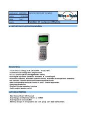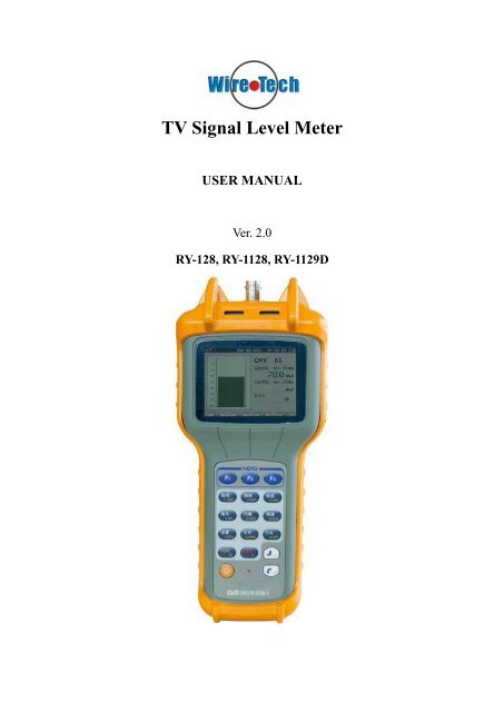
TV Signal Level Meter - Wire-Tech
TV Signal Level Meter - Wire-Tech
TV Signal Level Meter - Wire-Tech

Create successful ePaper yourself
Turn your PDF publications into a flip-book with our unique Google optimized e-Paper software.
<strong>TV</strong> <strong>Signal</strong> <strong>Level</strong> <strong>Meter</strong><br />
USER MANUAL<br />
Ver. 2.0<br />
RY-128, RY-1128, RY-1129D
Digital <strong>Signal</strong> <strong>Level</strong> <strong>Meter</strong><br />
II
Digital <strong>Signal</strong> <strong>Level</strong> <strong>Meter</strong><br />
Please read this manual carefully when using this product for the<br />
first time<br />
Warranty<br />
This product reaches published quality standards without any limitation in<br />
material and manufacturing process. The guarantee does not apply to those used<br />
products and exhibits.<br />
Generally if within warranty period, we are responsible for free maintenance.<br />
Users will be asked to pay the freight that return to our company plus insurance, and<br />
we will pay the charge of maintain and express<br />
The following does not belong to the scope of the warranty:<br />
(1) External force (impact, falling, etc.) caused panel, switches, chassis deformation<br />
and damage related to the internal device.<br />
(2) Unauthorized dismantle meter.<br />
(3) The damage when loading , user should check the meter when get it, please<br />
negotiate with shipping company when find problem caused by transportation.<br />
Only the consignee (individuals and units) have the right to claim to the transport<br />
carrier.<br />
(4) Use any other battery charger, which caused damage to the battery or line.<br />
(5) 7.2 V Ni-MH batteries<br />
I
Digital <strong>Signal</strong> <strong>Level</strong> <strong>Meter</strong><br />
Notice:<br />
1. Maintain the cleanliness of meter; don’t place it in the bad conditions. Do not use<br />
organic solvents, acids, alkalis; solvents scrub the surface of it.<br />
2. Make sure to avoid strong vibration, and any external force on the LCD screen<br />
which could cause damage.<br />
3. Charge batteries every six months if meter is not used for an extended period of<br />
time.<br />
4. Model 128D/1128D/1129D’s frequency range is from 5Mhz to 870Mhz. And the<br />
model 128/1128/1129’s is from 47Mhz to 870Mhz.<br />
The technical specifications and operating methods included in this<br />
manual are subject to changes without notice. In case of any inquires<br />
after a period of usage, please consult the manufacturer.<br />
II
Digital <strong>Signal</strong> <strong>Level</strong> <strong>Meter</strong><br />
Contents<br />
Chapter 1. General Information............................................1<br />
1.1 What’s the 1129D(128D/1128D) ............................................ 1<br />
1.2 Identify Components ............................................................... 1<br />
Chapter 2. Operation Guide.................................................3<br />
2.1 Start-up ......................................................................................... 3<br />
2.1.1 Menu..................................................................................... 3<br />
2.2 Settings .......................................................................................... 3<br />
2.2.1 Learn user plan ................................................................... 4<br />
2.2.2 Shutdown time..................................................................... 5<br />
2.2.3 Date & Time ........................................................................ 5<br />
2.2.4 Volume Setting..................................................................... 6<br />
2.2.5 <strong>Level</strong> Units ........................................................................... 6<br />
2.2.6 Select User Plan................................................................... 7<br />
2.2.7 Edit User Plan ..................................................................... 7<br />
2.2.8 Probe Compensation........................................................... 8<br />
2.2.9 Value Amendment ............................................................... 9<br />
2.2.10 Limit Setup ...................................................................... 10<br />
III
Digital <strong>Signal</strong> <strong>Level</strong> <strong>Meter</strong><br />
2.2.11 Load Default (Reset to factory data)............................. 10<br />
2.2.12 System Information ........................................................ 10<br />
2.3 Measurement .............................................................................. 10<br />
2.3.1 <strong>Signal</strong> measurement of digital or analog channel.......... 10<br />
(1) Digital channel ............................................................... 10<br />
(2) Analog channel .............................................................. 12<br />
2.3.2 Automatical measurement ............................................... 13<br />
2.3.3 Spectrum measurement.................................................... 14<br />
2.3.4 Scan measurement ............................................................ 15<br />
2.3.5 Tilt Measurement.............................................................. 17<br />
2.3.6 Trunk Line Voltage Measurement................................... 18<br />
2.3.7 Carrier-Noise Measurement ............................................ 18<br />
2.3.8 File ...................................................................................... 19<br />
Chapter 3. Power Supply .................................................. 20<br />
Chapter 4. <strong>Tech</strong>nical Data ................................................. 21<br />
Frequency/ Channel......................................................................... 21<br />
<strong>Level</strong> Measurement.......................................................................... 21<br />
Carrier-Noise Ratio(C/N)........................................................... 21<br />
Voltage Measurement ...................................................................... 21<br />
Other ................................................................................................. 22<br />
Power................................................................................................. 22<br />
Annex................................................................................................. 22<br />
IV
Digital <strong>Signal</strong> <strong>Level</strong> <strong>Meter</strong><br />
V
Digital <strong>Signal</strong> <strong>Level</strong> <strong>Meter</strong><br />
Chapter 1. General Information<br />
1.1 What’s the 1129D(128D/1128D)<br />
1129D(128D/1128D) is a portable signal level meter is a powerful device designed<br />
for the CA<strong>TV</strong> engineers and managers. The accuracy of the data is guaranteed by the<br />
RF signal processing system and MCU technology. So this device can measure data<br />
for every technical indicator of the CA<strong>TV</strong> system with high-resolution color display..<br />
This device is special for its function of analyzing all the technical indicators<br />
generated by the signal <strong>TV</strong>.<br />
1.2 Identify Components<br />
1
Digital <strong>Signal</strong> <strong>Level</strong> <strong>Meter</strong><br />
(1) RF (Radio Frequency) connector<br />
This connector can be changed to the type BNC or F according to the user’s need.<br />
(2) LCD (liquid crystal display) display<br />
It shows every parameter measured by the selected function. The contrast of the<br />
screen adapt to the environment automacitally.<br />
(3) Function Keys<br />
Contained four keys F1 – F4, The functions of the keys are according to the<br />
interface being used.<br />
(4) Number Keys<br />
You can input the certain channel or frequency with the key 0 – 9. In addition, the<br />
key 0 is the shortcut of channel setting in the single-channel level measurement.<br />
(5) Multi-function Keys<br />
Clear Key (C), Dot Key (.)<br />
(6) Arrow Keys<br />
Up, Down, Left and Right Key<br />
(7) Channel / Enter Key<br />
(8) Frequency Key<br />
(9) Menu Key<br />
(10) Power Key<br />
(11) Speaker<br />
(12) Battery Charge Socket<br />
After plugging in the accumulator charging socket, the red charging indicator light<br />
will be turned on. If the device is in operation, the power is supplied by the<br />
charger, else, the accumulator is charging..<br />
(13) Charging Indicator Light<br />
(14) PC Interface Socket<br />
2
Digital <strong>Signal</strong> <strong>Level</strong> <strong>Meter</strong><br />
Chapter 2. Operation Guide<br />
2.1 Start-up<br />
When the POWER Key is pressed, a short beep can be heard. Then the device will<br />
check itself on while displaying starting picture and information including the<br />
manufacturer, the meter type, the serial number ,then the menu follows.<br />
2.1.1 Menu<br />
When Menu key is pressed, menu mode is entered and you can choose the<br />
measurement mode which is most suitable for your needs (Fig. 2), including<br />
digital/analog signal level measurement mode, automatic mode, spectrum mode, scan<br />
mode, tilt mode, voltage mode, C/N mode, file mode, setup mode..<br />
Fig. 2<br />
2.2 Settings<br />
Before collecting the data, we need to make some changes of the settings of the<br />
device according to the current <strong>TV</strong> system. All the settings are saved in the storage of<br />
the device, and nothing will be changed until reset.<br />
When entered the menu mode, you can press the arrow keys to choose the icon and<br />
press Enter Key(CH/ENTER), then, you can browse all the settings by pressing the<br />
Arrow Keys.(Fig. 3), including:<br />
shutdown time<br />
date and time<br />
volume<br />
level units<br />
select user plan<br />
edit user plan<br />
learn user plan<br />
probe compensation<br />
value amendment<br />
3
Digital <strong>Signal</strong> <strong>Level</strong> <strong>Meter</strong><br />
limit setup<br />
restore<br />
system information<br />
Fig. 3<br />
2.2.1 Learn user plan<br />
In order to improve the efficiency, create an user plan is suggested before starting the<br />
device.<br />
Press the “learn user plan”, then choose the name of the plan to create. After pressing<br />
the Enter Key, the status before creating will be displayed on the LCD (Fig. 4)<br />
Fig. 4<br />
The steps to create a user plan:<br />
1. Connect to CA<strong>TV</strong><br />
2. Press F1/F2 to choose the channel plan as model<br />
3. Press F3 to start creating. The progress bar at the bottom of the screen shows the<br />
completeness. You can choose to save or not after finishing the creating<br />
procedure.<br />
4
Digital <strong>Signal</strong> <strong>Level</strong> <strong>Meter</strong><br />
The channel plan created will be saved in the device.<br />
Attention:<br />
A CA<strong>TV</strong> must be connected to the device when you are creating a user plan.<br />
The device will recognize every channel which level is greater than 40dBmV and all<br />
of them are showed in the user plan. And it can distinguish the digital or analog<br />
signals. But it may need editing by the user due to the complexity of signals.<br />
The user can edit the user plan in the “edit user plan” option.<br />
2.2.2 Shutdown time<br />
Fig. 5<br />
In order to save power, the device has the function of shutdown automatically when it<br />
is in the idle status.<br />
Choose the “shutdown time” icon in the setup mode and press the Enter Key (Fig. 5).<br />
After that, press the Arrow Keys to choose the shutdown time you need, and press<br />
Enter to save.<br />
Four options of Shutdown Time:<br />
3min<br />
5min<br />
10min<br />
Always On<br />
2.2.3 Date & Time<br />
5
Digital <strong>Signal</strong> <strong>Level</strong> <strong>Meter</strong><br />
Fig. 6<br />
Choose the “Date & Time” icon in the setup mode and press Enter (Fig. 6). Use the<br />
Arrow Keys to choose the date and time need to be edited. Then, press the Number<br />
Keys to enter date and time (Date format: yy/mm/dd ; Time format: hh/mm/ss). They<br />
will be saved by pressing the Enter Key.<br />
2.2.4 Volume Setting<br />
Fig. 7<br />
Choose the “Volume Setting” and press the Enter Key (Fig. 7). Then press the Arrow<br />
Keys to change the volume and press the Enter Key to save.<br />
2.2.5 <strong>Level</strong> Units<br />
Choose the “<strong>Level</strong> Units” and press the Enter Key (Fig. 8). Then press the Arrow<br />
Keys to change the level unit and the Enter Key to save.<br />
6
Digital <strong>Signal</strong> <strong>Level</strong> <strong>Meter</strong><br />
Fig. 8<br />
<strong>Level</strong> Units:<br />
dBuv<br />
dBmv<br />
dBm<br />
2.2.6 Select User Plan<br />
Fig. 9<br />
Choose the “<strong>Level</strong> Units” and press the Enter Key (Fig. 9). Then press the Arrow<br />
Keys to select the channel plan you need and press the Enter Key to save.<br />
2.2.7 Edit User Plan<br />
You can edit the parameter of the channel plan including channel name, select or not,<br />
channel type, frequency, sound intermediate frequency of analog channel and central<br />
frequency, bandwidth, QAM, symbol rate.<br />
7
Digital <strong>Signal</strong> <strong>Level</strong> <strong>Meter</strong><br />
Fig. 10<br />
Type:<br />
Digi / Anal<br />
BW:<br />
1MHz – 9.9MHz<br />
QAM:<br />
16 / 32 / 64 / 128 / 256 QAM<br />
SR:<br />
1M – 7M<br />
Choose the “Edit User Plan” icon in the setup mode. After pressing the Enter Key,<br />
you can see the parameter setting screen. Select the channel need to be edited by<br />
pressing the Arrow Keys and enter setting state by the Enter Key (Fig. 10). The<br />
“Select” and “Type” option can be changed by Left key or Right Key, and the other<br />
options can be edited by the Number Keys, saved by the Enter Key. At last choose<br />
“save & return” and press the Enter Key to save.<br />
Note:<br />
You can select “ALL” to change all the channels’ parameters instead of change<br />
them one by one.<br />
2.2.8 Probe Compensation<br />
Press the Enter Key as the “Probe Compensation” option is chosen(Fig. 11).<br />
8
Digital <strong>Signal</strong> <strong>Level</strong> <strong>Meter</strong><br />
Fig. 11<br />
Press Left or Right Key to select the position to edit, and Up and Down Key to change<br />
the revision, Enter Key to save.<br />
2.2.9 Value Amendment<br />
Every device has been tested before leaving factory. Its frequency response has<br />
gone through restrict digital modification and already been saved in the memory.<br />
But some measurement deviations will probably appear due to long-time use or<br />
component aging. This device enable user to adjust this measurement deviation.<br />
Only with a standard instrument or a standard signal source, user can correct this<br />
device and make its measurement result more accurate.<br />
This function is also suitable for user’s special measurement requirement.<br />
In the setup mode, select the “correct DB” icon and press the Enter Key to start as<br />
shown in Fig. 12 .<br />
Fig. 12<br />
Under this situation, press F1 and F2 to adjust modification levels, and F3 to save.<br />
In addition, you can change the channel or frequency easily by pressing Left Key and<br />
9
Digital <strong>Signal</strong> <strong>Level</strong> <strong>Meter</strong><br />
Right Key or the exact number and the CH or Mhz Key. When it’s in the frequency<br />
mode, the CH Key with the Left or Right Key will make the device to change to the<br />
channel situation.<br />
Continue to adjust the channel to be corrected to modify it until completed.<br />
2.2.10 Limit Setup<br />
You can set the limits in this function as your need.<br />
Select the “Limit Setup” icon and press the Enter Key. Then the limit window will<br />
be shown on the LCD. Choose the option you need to edit by pressing the Up and<br />
Down keys, and adjust the value by the Left and Right Keys. At last, select “save &<br />
return” and press Enter Key to save.<br />
2.2.11 Load Default (Reset to factory data)<br />
If there’re some settings is not ideal, you can recover the device with the factory<br />
data.<br />
In the setup mode, select the “Load Default” icon and press the Enter Key. Then<br />
choose OK or Cancel with Left, Right and Enter Key in the confirmation window.<br />
2.2.12 System Information<br />
It shows the serial number of the device in your hand.<br />
2.3 Measurement<br />
2.3.1 <strong>Signal</strong> measurement of digital or analog channel<br />
Select the “<strong>Level</strong>” icon and press the Enter Key ,then the level measurement screen<br />
is shown.<br />
(1) Digital channel<br />
If the certain channel in the selected plan is digital type, then the device enter<br />
the digital channel signal level measurement. (Fig. 13)<br />
10
Digital <strong>Signal</strong> <strong>Level</strong> <strong>Meter</strong><br />
Fig. 13<br />
The “CHD” in front of the channel number shows that it is the digital signal to<br />
be measured, and the level displayed on the screen is average power.<br />
The Function Key icons’ definition:<br />
: spectrum mode<br />
: NC<br />
: QAM (It appears in 1128D and 1129D)<br />
: pagedown<br />
: pageup<br />
: save file<br />
: setting<br />
: return<br />
Press F1 to enter the spectrum mode.(The operation in the spectrum mode is<br />
shown in 2.3.3)<br />
Press F2 to change to frequency mode. At this time pressing F3 can turn the<br />
volume up and down. And press F2 again to return to channel mode.<br />
Press F3 to start QAM measurement (Fig. 14). Using this function you can<br />
measure the indicators just like MER, BER, constellation (1129D only) and so on.<br />
You can save MER, BER, and constellation by pressing F1. And press F2 to open<br />
the saved files, F3 to refresh, F4 to return.<br />
11
Digital <strong>Signal</strong> <strong>Level</strong> <strong>Meter</strong><br />
Fig. 14<br />
Press F4 to display the next page of the function Keys. Then press F1 to save<br />
the level of the digital signal channel, and F2 to set this channel.<br />
The ‘0’ Key is the shortcut of setting.<br />
○1 change the measuring channel<br />
Press the Left and Right Key under the channel mode to change the measuring<br />
channel following the order of the using plan.<br />
Under the channel mode, input the channel number by pressing the Number<br />
Keys directly and then press the CH Key to change the measuring channel.<br />
Attention:<br />
Every channel number input must be in the using plan, or it is invalid.<br />
○2 change the measuring frequency<br />
Pressing the Number Keys to input the exact frequency and the Mhz Keys can<br />
change the measuring frequency<br />
Under the frequency mode , press MHz, lock on the number to change the step<br />
to 10KHz, 100KHz, 1MHz, 10MHz, 100MHz, and change the measuring<br />
frequency by Arrow Keys.<br />
(2) Analog channel<br />
If the certain channel in the selected plan is analog type, then the device enter<br />
the analog channel signal level measurement. (Fig. 15)<br />
12
Digital <strong>Signal</strong> <strong>Level</strong> <strong>Meter</strong><br />
Fig. 15<br />
The “CHV” in front of the channel number shows that it is analog signal to<br />
measure.<br />
The basic operation is like the signal measurement of digital channel.<br />
2.3.2 Automatical measurement<br />
Select the “AUTO” icon and press the Enter Key to enter the Automatical<br />
measurement mode.<br />
The Function Key icons’ definition:<br />
: edit<br />
: delete<br />
: start<br />
: return<br />
Press F1 to the auto project setting screen (Fig. 16) which contain the file name and<br />
five channels. Press Up Key and Down Key to change the pointer, Left Key and<br />
Right Key to change the channel number and input the name of the file by the<br />
Number Keys. At last select “save & return” and press the Enter Key.<br />
13
Digital <strong>Signal</strong> <strong>Level</strong> <strong>Meter</strong><br />
Fig. 16<br />
Press F2 to delete the selected auto project.<br />
Press F3 to start measuring the five channels in the selected auto project.<br />
Press F4 to return.<br />
2.3.3 Spectrum measurement<br />
Select the “SPECT” icon and press the Enter Key to enter the spectrum<br />
measurement mode.(Fig. 17)<br />
Fig. 17<br />
The Function Key icons’ definition:<br />
: zoom in (change BW)<br />
: zoom out (change BW)<br />
: save<br />
: zoom in (change Scale)<br />
14
Digital <strong>Signal</strong> <strong>Level</strong> <strong>Meter</strong><br />
: zoom out (change Scale)<br />
: pagedown<br />
: pageup<br />
: return<br />
1 step adjusting<br />
Press F1 ( ) or F2 ( ) to zoom in or out. The step available: 10KHz,<br />
20KHz, 30KHz, 50KHz,100KHz,500KHz.<br />
2 scale adjusting<br />
Press F4 to switch the Function Key to the next page. Then press F1 (<br />
) and<br />
F2 (<br />
) to change the scale among 20,10,5,2,1 db/div.<br />
3 spectrum central frequency input<br />
Press the Numbers Keys and the MHz Key. Then the device will start the spectrum<br />
measurement with the new spectrum central frequency.<br />
4 level reference adjusting<br />
The level reference displays at the bottom of the right side . It can be adjusted by<br />
pressing Up and Down Key.<br />
The step of level reference is 5dB.<br />
2.3.4 Scan measurement<br />
Select the “SCAN” icon and press the Enter Key to enter the scan measurement<br />
mode.(Fig. 18)<br />
15
Digital <strong>Signal</strong> <strong>Level</strong> <strong>Meter</strong><br />
The Function Key icons’ definition:<br />
Fig. 18<br />
: zoom in<br />
: zoom out<br />
: save<br />
: zoom in (change Scale)<br />
: zoom out (change Scale)<br />
: pagedown<br />
: pageup<br />
: return<br />
1 level reference adjusting<br />
The level reference displays at the bottom of the right side . It can be adjusted by<br />
pressing Up and Down Key.<br />
The step of level reference is 5dB.<br />
2 zoom in and out<br />
Press F1 ( ) and F2 ( ).<br />
3 save<br />
Press F3 ( ).<br />
16
Digital <strong>Signal</strong> <strong>Level</strong> <strong>Meter</strong><br />
4 scale adjusting<br />
Press F4 to switch the Function Key to the next page. Then press F1 (<br />
) and<br />
F2 (<br />
) to change the scale among 20,10,5,2,1 db/div.<br />
5 mark moving<br />
Press Left and Right Key to move the mark ,and at the bottom of the LCD there’s<br />
the channel number and frequency<br />
6 starting channel input<br />
Press the Numbers Keys and the CH Key. Then the device will start the scan<br />
measurement with the new starting channel.<br />
2.3.5 Tilt Measurement<br />
Select the “TILT” icon and press the Enter Key to enter the tilt measurement<br />
mode.(Fig. 19)<br />
Fig. 19<br />
There’re 12 vertical bands each represents one channel signal level. You can<br />
compare the channels’ amplitude-frequency response through the multi-channel<br />
measurement which is also called tilt measurement.<br />
You can change the channel on the mark by pressing Up/Down Key and Enter Key<br />
to save. And also you can move the mark by Left/Right Key.<br />
At the bottom of the LCD there’re the maximum channel’s number and frequency<br />
and the minimum one, and also △dB value displaying on the right.<br />
Attention:<br />
Please make sure the channels which will be measured array continuously.<br />
17
Digital <strong>Signal</strong> <strong>Level</strong> <strong>Meter</strong><br />
2.3.6 Trunk Line Voltage Measurement<br />
Select the “VOLT” icon and press the Enter Key to enter the voltage measurement<br />
mode.(Fig. 20)<br />
Fig. 20<br />
When the trunk line is charged with current, the meter will automatically recognize<br />
the voltage and distinguish "AC" from "DC" by displaying them on the screen.<br />
2.3.7 Carrier-Noise Measurement<br />
Select the “C/N” icon and press the Enter Key to enter the Carrier-Noise<br />
measurement mode.(Fig. 21)<br />
Under the signal measurement of analog channel mode, pressing F3 can also enter<br />
this measurement.<br />
Fig. 21<br />
Attention:<br />
1. This function is valid only when the signal input level is higher than 60dB.<br />
18
Digital <strong>Signal</strong> <strong>Level</strong> <strong>Meter</strong><br />
2. The signal-noise ratio is measured online, thus the measured result is used only<br />
as reference.<br />
2.3.8 File<br />
(1) save<br />
Under the mode of digital MER/BER measurement, spectrum measurement, scan<br />
measurement, tilt measurement and so on, press the function key corresponding to<br />
“save” to save the files.<br />
(2) read<br />
Select the “FILE” icon and press the Enter Key to enter the file mode.(Fig. 22)<br />
Fig. 22<br />
Press Up/Down Key to choose the file need to read or delete, then press F3 to read,<br />
F2 to delete.<br />
19
Digital <strong>Signal</strong> <strong>Level</strong> <strong>Meter</strong><br />
Chapter 3. Power Supply<br />
Built-in high-performance rechargeable batteries (7.2 V Ni-MH batteries) to provide<br />
the power source of device, it also could use AC power supply that equipped with the<br />
instrument. It could work continuously more than 4 hours in a status of adequate<br />
electricity,<br />
Notes:<br />
1. <strong>Meter</strong> has power saving function, the equipment will be shut down<br />
automatically if five minutes or longer without keyboard operation.<br />
2. The meter has the function for testing the battery voltage automatically; users<br />
can determine the consumption condition of the battery by way of checking the<br />
volume of the battery voltage. It also has the function of “low-voltage alarm”, when it<br />
needs to be charged, the device will give out the alarm sound so as to remind the<br />
users to charge, otherwise, the device will automatically shut down.<br />
3. When the device is being charged, please use its own charger. When the users<br />
charge up, please insert the battery charger direct current output in the charging<br />
socket at the bottom of the instrument; another terminal of the battery charger should<br />
be inserted in the AC 220V power source socket, there is an indicator light on the<br />
instrument panel, if the indicator light turns red, it means that the battery charger is<br />
switched on with the power source and instrument, the instrument is being charged.<br />
4. Both status of starting and shutdown could be charged. It takes about 8 hours to<br />
complete charging under shutdown mode, remove the connector between the charge<br />
and AC current when the charge is completed, and keep charger to prepare for using<br />
in next time.<br />
Please use only the charger provided with the meter, using any other battery<br />
charger may overheat or distort the meter, or cause fire, injury or harm to the<br />
environment, and we will not be responsible for warranty or compensation.<br />
20
Digital <strong>Signal</strong> <strong>Level</strong> <strong>Meter</strong><br />
Chapter 4. <strong>Tech</strong>nical Data<br />
Frequency/ Channel<br />
Frequency range: 5(47)MHz ~ 870MHz<br />
Channel range:???<br />
Frequency resolution: 10 KHz<br />
Measurement bandwidth: 280KHz<br />
<strong>Level</strong> Measurement<br />
Range: 25dBuV ~ 120 dBuV<br />
Accuracy: ±2dB<br />
Resolution: 0.1 dB<br />
Scan: peak value demodulation<br />
Input impedance: 75Ω<br />
Carrier-Noise Ratio(C/N)<br />
Input range: 70dBuV—105dBuV<br />
Accuracy: ±2 dBuV<br />
Voltage Measurement<br />
Input range: 10 ~ 80V(AC/DC)<br />
Accuracy: ±2V<br />
Resolution: 0.1V<br />
21
Digital <strong>Signal</strong> <strong>Level</strong> <strong>Meter</strong><br />
<strong>Tech</strong>nical indicators above worked in temperature 25℃<br />
Other<br />
Dimensions: 215mm×93mm×48mm<br />
Net Weight: < 550g<br />
Temperature: -10℃ ~ 45℃<br />
Display: 320 X 240 TFT LCD<br />
Audio Output: Build-in speaker<br />
Power<br />
DC supply: 7.2V rechargeable battery<br />
AC Supply: AC220V/50Hz ±10%<br />
Working time:<br />
>4hrs (full charged battery)<br />
Charging Time: ≤8hrs<br />
Annex<br />
Specifically rechargeable power: a charger<br />
RF input adapter: Q9 / F 1<br />
Instrument kits: 1<br />
Manual: 1<br />
22