PROPERTIES OF CO2 AS A REFRIGERANT - Centro Studi Galileo
PROPERTIES OF CO2 AS A REFRIGERANT - Centro Studi Galileo
PROPERTIES OF CO2 AS A REFRIGERANT - Centro Studi Galileo

Create successful ePaper yourself
Turn your PDF publications into a flip-book with our unique Google optimized e-Paper software.
CENTRO STUDI GALILEO INDUSTRIA & FORMAZIONE<br />
UNIVERSITÀ DEGLI STUDI DI MILANO<br />
CENTRO DI RICERCA PER L’AMBIENTE E L’IMPRESA<br />
EUROPEAN SEMINAR – CO 2 <strong>AS</strong> A <strong>REFRIGERANT</strong><br />
<strong>PROPERTIES</strong> <strong>OF</strong> CO 2 <strong>AS</strong> A <strong>REFRIGERANT</strong><br />
Alberto Cavallini - alcav@unipd.it<br />
Dipartimento di Fisica Tecnica dell’Università di Padova<br />
Via Venezia, 1 – I 35131 Padova PD, Italy<br />
Summary: In the beginnings of mechanical refrigeration, at the end of the nineteenth<br />
century, Carbon Dioxide was one of the first refrigerants to be used in compression type<br />
refrigerating machines, later gaining widespread application mainly onboard of refrigerated<br />
ships, but common in other sectors of refrigeration as well.<br />
It was only immediately after World War II that CO 2 rapidly eclipsed as a refrigerant,<br />
due to the advent of the synthesised halogenated working fluids, addressed as safe and ideal<br />
refrigerants at that time.<br />
Because of the stratospheric Ozone depletion environmental issue, CFC and HCFC<br />
working fluids are now phased out of use in Europe under EU Regulation 2037/2000. The<br />
Global Warming environmental issue casts concern over the use of the new HFC fluids as<br />
substitute refrigerants, because of their high GWP values, which make them subject to<br />
regulations under the Kyoto Protocol.<br />
In this mixed situation, CO 2 is being revisited as a fully environmentally friendly and safe<br />
refrigerant. An intense research activity on its prospective applications is underway in many<br />
research establishments in Europe, Japan and North America, and important results have<br />
already been reached in exploiting the peculiar characteristics of this high-pressure fluid<br />
operated with a transcritical cycle. In some applications CO 2 systems have been already<br />
commercialised; this yields for heat pump water heaters, as a brine in indirect systems and in<br />
the low temperature stage of cascade systems.<br />
The paper critically analyses the prospects for the future return of CO 2 as a working<br />
fluid, or sometimes as a brine with change of phase, in important application areas. These<br />
include air conditioning and heat pump systems in the residential and commercial sectors,<br />
commercial and transport refrigeration and mobile air conditioning.<br />
Keywords: Carbon Dioxide, CO 2 , Refrigerants, Refrigeration, Heat Pumps.<br />
1. HISTORICAL HINTS<br />
The dawn of mechanical refrigeration preceded the possibility of recurring to chemical<br />
synthesis to obtain compounds foreign to nature, and therefore surely the first refrigerants<br />
have been natural fluids. Some of them have completely disappeared, others are still widely<br />
applied today, and some others, although abandoned in the past, are now reconsidered. This
happens under the emergency of the environmental issues put forth by the use of synthesised<br />
refrigerants, that is the depletion of the stratospheric ozone and the display of the<br />
antropogenic greenhouse effect.<br />
A compound certainly disappeared in the use as a refrigerant is the stinky distillate of<br />
caoutchou, called caoutchoucine, very first working fluid in a vapour compression<br />
refrigerating machine built (although with limited success) by John Hague. This happened<br />
shortly after 1834, when Hague’s mentor Jacob Perkins applied in London for the first patent<br />
relative to this kind of machine; actually Jacob Perkins had thought of ethyl ether (then called<br />
sulphuric ether) as the refrigerant for his new machine.<br />
The dangerous sulphuric dioxide too is a natural fluid used in the past as a refrigerant,<br />
and then abandoned without any chance of reconsideration. It permitted the birth of domestic<br />
refrigeration, but it was used also in the commercial sector and even in big air-conditioning<br />
plants, as in the Rio de Janeiro Opera House in 1904.<br />
Ammonia and some paraffinic hydrocarbons are instead among the working fluids that,<br />
already used since the beginning of mechanical refrigeration, never lost their importance in<br />
this application. Hydrocarbons are still extensively used in industrial refrigeration (where<br />
local safety issues, due to their high flammability, can be adequately addressed), and find new<br />
applications (at least in Europe) in domestic refrigeration and low-charge unitary air<br />
conditioners. As to ammonia, it is still widely used in the sector of treatment and preservation<br />
of foodstuffs, while new applications have already entered the market, as for example in the<br />
sector of water chillers for air-conditioning (mainly for installation in the open air). The<br />
refrigerant substitution issue opens new interesting perspectives for all these natural fluids.<br />
Carbon dioxide too has been a natural agent extensively used in the past as a working<br />
fluid in compression-type refrigerating machines, above all in the initial forty years of the past<br />
century. Phased out after World War II, this fluid is now revisited and vastly investigated as a<br />
possible working fluid for a wide variety of applications. This action is driven by the search<br />
for natural fluids fully compatible with the environment and intrinsically safe even in the<br />
immediate surroundings, as a substitute for the old generation synthetic fluids.<br />
Old Physics books report that carbon dioxide was solidified for the first time in 1835 by<br />
the French physicist Thilorier, and in turn used as a cooling agent (dry ice) to solidify<br />
mercury. In 1867 the American inventor Lowe described how carbon dioxide could be used in<br />
refrigeration: Franz Windhausen from Brunswick in Germany, in 1886 patented a compressor<br />
for a carbon dioxide refrigerating machine. The following year the British Company J&E Hall<br />
bought a licence to build a CO 2 compressor from Windhausen himself. The same Company<br />
built the first two-stage CO 2 compressor as well (Cavallini and Steimle 1998).<br />
This can be considered the starting point of the extended use of carbon dioxide as a<br />
working fluid in mechanical refrigeration. Some previous attempt is also known, as for<br />
example by Carl Von Linde, who had designed a refrigerating machine working with CO 2 for<br />
the Company F. Krupp of Essen, in Germany.<br />
It is commonly believed that carbon dioxide was exclusively used as a refrigerant aboard<br />
ships. It is certainly true that, of the three sectors which drove the rapid expansion of<br />
mechanical refrigeration at the beginning of the twentieth century, that is ice manufacturing,<br />
beer brewing and meat transportation from Australia and Latin America to Great Britain, this<br />
last one mainly involved the general use of equipment working with CO 2 as a refrigerant<br />
starting from 1890; before this date air-cycle machines were mainly employed. By 1910 J&E<br />
Hall had already installed 1800 refrigerating machines aboard ships.<br />
But there are also numerous examples of use of CO 2 refrigerating machines in different<br />
sectors. Examples are cooling of the ammunition magazine in warships, in breweries, in wine<br />
or liquor cellars, in slaughterhouses, in dairy industries, in artificial ice factories and also in<br />
all civil application where the safety issue was considered of prominent importance. The<br />
number of CO 2 compressor manufacturers rapidly increased in the first decade of the
twentieth century, in particular in the Central and North European Countries. A German<br />
manual of 1915 lists 29 CO 2 compressor manufacturers in North Europe, 24 of them in<br />
Germany, a number hard to believe nowadays.<br />
The entrance into the market, starting from 1931, of the new synthesised halogenated<br />
refrigerants marked the rapid and inexorable decline in the use of carbon dioxide as a<br />
refrigerant, which though withstood in the field for long. In 1946, 88 percent of the British<br />
Fleet still used CO 2 as the refrigerant, and in 1963, 22 percent of the ships recorded in the<br />
French Register of Shipping was equipped with CO 2 refrigerating machines.<br />
The reasons for this rapid decline lay certainly in the low energy efficiency of this<br />
equipment, and in the drastic reduction in refrigerating power when ambient temperature<br />
increases (problem soon evidenced in ships crossing the warm equatorial seas). But certainly<br />
also in the failure of CO 2 compressor manufacturers to conform their production to modern<br />
technological developments (more compact and faster equipment, and therefore less costly).<br />
2. <strong>PROPERTIES</strong> <strong>OF</strong> CARBON DIOXIDE <strong>AS</strong> A <strong>REFRIGERANT</strong><br />
Quite a few general properties of CO 2 (official designation R-744 (<strong>AS</strong>HRAE 1997)) are<br />
absolutely ideal for the use of this product as a working fluid in vapour compression<br />
refrigerating machines and heat pumps (Lorentzen 1994):<br />
<br />
<br />
<br />
<br />
<br />
carbon dioxide is very abundant in the environment, waste of many technological<br />
processes; its cost is thus extremely low, easily available anywhere, and its recovery<br />
from dismissed equipment or in maintenance is not required;<br />
being a natural fluid, its harmlessness to the biosphere is demonstrated, both as far as<br />
known actions are concerned in the immediate (as the depletion of stratospheric<br />
ozone), and with reference to possible still unknown harmful actions (an always<br />
possible danger in the use of new synthesised products foreign to nature, as the<br />
happenings with CFCs and DDT have shown). CO 2 is certainly a greenhouse gas, but<br />
for its possible use as a refrigerant one recurs to recovery from industrial waste. For<br />
this application therefore the added greenhouse impact is to be considered nil, as nil is<br />
of course its impact on the stratospheric ozone depletion;<br />
it is a product that displays no special local safety problem, as it is non-flammable<br />
and non-toxic. Gas heavier than air, it can accumulate in the lower part of a nonventilated<br />
ambient, especially in a basement, causing suffocation for lack of oxygen.<br />
Holds of ships may be prone to this kind of events;<br />
it is an inert product, compatible with all common materials encountered in a<br />
refrigerating circuit, both metals and plastics or elastomers;<br />
special synthetic lubricants have been developed and are now tentatively available for<br />
CO 2 . They seem suitable and are under close scrutiny, with good results so far. The<br />
three most interesting candidates are at the moment POE, Alkyl Naftenic (AN) and<br />
PVE products.<br />
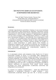
As far as thermodynamic properties of carbon dioxide are concerned, the state diagram p<br />
– h (pressure, in a logarithmic scale – specific enthalpy) is reproduced in Fig. 1. Table 1 gives<br />
values for some fundamental properties of carbon dioxide, together with those for R-22, and
0<br />
100<br />
some other in-kind refrigerants. R-22 will constitute a comparison synthesised refrigerant in<br />
the following of this discussion.<br />
Table 1. Characteristic properties of Carbon Dioxide and some other traditional refrigerants<br />
Fluid<br />
Critical<br />
Temperature<br />
[°C]<br />
Critical<br />
Pressure<br />
[bar]<br />
Saturation Pressure<br />
at –20°C at + 30°C<br />
[bar]<br />
Volumetric Latent<br />
Heat at –20 °C<br />
[kJ/m 3 ] (1)<br />
Molecular<br />
Mass<br />
[kg/kmol]<br />
CO 2 31.06 73.84 19.67 72.05 14592 44.01<br />
R-22 96.15 49.90 2.453 11.92 2371 86.47<br />
R-134a 101.06 40.59 1.327 7.702 1444 102.03<br />
R-410A 71.36 49.03 4.007 (2) 18.89 (2) 3756 72.59<br />
NH 3 132.25 113.33 1.901 11.672 2131 17.03<br />
(1) latent heat divided by the specific volume of dry saturated vapour.<br />
(2)<br />
refers to the liquid phase.<br />
The diagram and data in the Table evidence the peculiarities of CO 2 when used as a<br />
working fluid in the traditional refrigeration processes. The main difference, as compared to<br />
traditional refrigerants such as R-22, is the very low value of the critical temperature, 31 °C<br />
for R-744, that is around the maximum summer ambient temperature in Countries with<br />
tempered climate. As a consequence, in the traditional vapour compression refrigerating<br />
cycle, the process of heat rejection to the environment does not usually imply condensation of<br />
the working fluid carbon dioxide, but a dense gas progressive cooling at (ideally) a constant<br />
pressure higher than the critical pressure. This of course happens unless a heat sink (cooling<br />
water from a natural source, for example) is available at temperature around 20 °C or less, a<br />
more and more unusual circumstance in today’s world.<br />
200<br />
Pressure [bar]<br />
100<br />
73,84<br />
40<br />
20<br />
10<br />
p C<br />
CO 2<br />
SOLID - LIQUID<br />
T=-40°C<br />
=1000 kg/m 3<br />
T =31,06°C<br />
C<br />
500<br />
3,8<br />
20<br />
s=4,0 kJ/kgK<br />
60<br />
4,2<br />
140<br />
200<br />
180<br />
4,4<br />
50<br />
4,6<br />
20<br />
10<br />
100<br />
T=220°C<br />
-20<br />
0,2<br />
0,4<br />
X=0,6<br />
0,8<br />
40<br />
5,182<br />
4<br />
300<br />
TRIPLE POINT LINE<br />
400<br />
T =-56,57°C<br />
t<br />
SOLID - VAPOUR<br />
500 600 700 800<br />
-40<br />
4,8<br />
5<br />
900 1000<br />
Specific enthalpy [kJ/kg]<br />
Figure 1 – Thermodynamic diagram specific enthalpy – pressure for Carbon Dioxide.<br />
At design conditions a CO 2 refrigerating machine therefore does not usually work with a<br />
condenser, but rather with a high pressure gas cooler. The corresponding refrigerating cycle is
dubbed transcritical, inasmuch as it takes place between two isobars, the former at a pressure<br />
value lower than the critical one (evaporator), and the latter at a pressure above the critical<br />
one (gas cooler).<br />
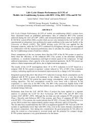
Figure 2 shows, in a pressure – enthalpy diagram, two ideal transcritical CO 2 cycles, at<br />
two different values for the gas cooler pressure. A peculiar feature of the transcritical cycle, as<br />
it appears in Fig. 2, is the existence of an optimum value for the gas cooler pressure, that<br />
brings about the maximum value for the cycle COP, once the other operating conditions have<br />
been fixed. In fact one can see in Fig. 2 how, by moving from cycle 1-2-3-4, with 90 bar gas<br />
cooler pressure, to cycle 1-2’-3’-4’, with 100 bar gas cooler pressure, both the refrigerating<br />
effect and the compression work increase (by Q 0 and W c respectively). It depends on the<br />
relative increases of these two quantities whether the COPincreases or decreases. To be noted<br />
that a constant value for the gas cooler exit temperature t 3 =t 3’ =40 °C was kept.<br />
100 bar<br />
90 bar<br />
3'<br />
3<br />
2'<br />
2<br />
Pressure<br />
40°C<br />
-20° C<br />
4'<br />
4 1<br />
Q 0<br />
Q 0<br />
Specific enthalpy<br />
W c<br />
W c<br />
Figure 2 –<br />
Two transcritical refrigerating cycles (with different values for the gas cooler<br />
pressure) depicted in the h-p diagram for CO 2 .<br />
The shape of the constant-temperature lines (the isotherm at 40 °C is plotted in the figure)<br />
explains why an optimum gas cooler pressure exists. This evidently depends on all specific<br />
conditions defining the cycle considered (evaporation temperature, possible superheat of the<br />
compressor suction gas, isoentropic compression efficiency, gas temperature at gas cooler<br />
exit, etc.). For an ideal simple transcritical cycle, such as the one depicted in Fig. 2, the value<br />
of the optimum pressure p opt of the gas cooler can be estimated, as a function of evaporation<br />
temperature t e and gas temperature at gas cooler exit t gce , by the equation (Liao and Jakobsen<br />
1998):<br />
p<br />
opt<br />
with<br />
=<br />
t<br />
( 2.778 0.0157 te<br />
) t<br />
gce<br />
+ ( 0.381<br />
te<br />
9.34)<br />
and t in [ ° C] , and p in [ bar]<br />
e<br />
gce<br />
opt<br />
40°<br />
C < te<br />
< + 5°<br />
C ; 31°<br />
C < t<br />
gce<br />
< 50°<br />
C<br />
The above equation is valid for isoentropic compression and dry saturated vapour at<br />
compressor suction.<br />
The same equation holds good for cycles with isoentropic efficiency less than 1, provided<br />
that it can be considered constant (that is, independent of the compression pressure ratio).<br />
(1)
In all cases, not only with reference to an ideal simple cycle, the trend of the cycle<br />
coefficient of performance as a function of the gas cooler pressure for p>p opt is rather flat.<br />
Therefore a slight overpressure in the gas cooler with respect to the optimum, does not<br />
penalise too much the cycle efficiency. On the other hand, a gas cooler pressure below the<br />
optimum value can sometimes drastically penalise the cycle efficiency. A proper control of<br />
the high-pressure level is indispensable to take best advantage of CO 2 refrigeration<br />
technology.<br />
A further important difference of CO 2 transcritical cycles, as compared to traditional<br />
refrigerating cycles, is given by the much higher pressure levels (see data reported in Tab. 1),<br />
at equivalent working conditions as far as temperatures of the external source and sink are<br />
concerned.<br />
It is no doubt that high pressure levels penalise the structural design of components of a<br />
refrigerating circuit, and in particular of the compressor; nevertheless their reduced sizes<br />
counterbalance this drawback. As compared to traditional refrigerants, the reduced volume<br />
flow rate of CO 2 necessary to yield a certain refrigerating power is evidenced by the value of<br />
the volumetric latent heat reported in Tab. 1. This is six times larger for CO 2 than for R-22,<br />
even if one must also take into account the high vapour quality of CO 2 at the evaporator inlet,<br />
as compared to that of R-22 in comparable situations, proper to the transcritical cycle.<br />
The high pressure level with CO 2 also brings about a reduced penalty due to the fluid<br />
pressure loss when designing the refrigerating circuit appropriately.<br />
From what said above it can be concluded that equipment with CO 2 as the refrigerant, in<br />
spite of the higher working pressure, is not necessarily heavier or bulkier or potentially more<br />
dangerous as compared to equivalent equipment operated with the traditional working fluids.<br />
This is due to the smaller flow cross sections of the components, consequent on the reduced<br />
refrigerant volume flow rate.<br />
Moreover, at equivalent working conditions, the compressor pressure ratio with CO 2 is<br />
notably lower than with traditional refrigerants. Together with a higher pressure level, this<br />
fact makes it possible to get higher compression isoentropic efficiencies, with advantages in<br />
energy consumption. On the other hand, CO 2 compressors work with much higher differential<br />
pressures than traditional refrigerating compressors, and this fact may enhance backflow<br />
losses.<br />
Another peculiarity of carbon dioxide is evident in the diagram of Fig. 1: the triple point<br />
pressure (p t =5.18 bar) is above that of the natural environment. At atmospheric pressure the<br />
transition from solid to gas (sublimation process) takes place at temperature t t =-78.9 °C, and<br />
the cooling effect is exploited in the so-called dry ice. In mechanical refrigeration this means<br />
that, in the event of collapse of a circuit, residual CO 2 solidifies in the plant at around –79 °C,<br />
sublimating successively into the atmosphere.<br />
3. THE CO 2 TRANSCRITICAL REFRIGERATING CYCLE<br />
Energy performance of a CO 2 transcritical cycle is now discussed and compared with that<br />
of a traditional refrigerating cycle operated with conventional working fluids. To make the<br />
discussion concrete and to be able to argue about definite numerical values, two refrigerating<br />
cycles are directly analysed: a transcritical one operating with CO 2 , and a traditional one<br />
operated with R-22; this last refrigerant is in fact often taken as a bench-mark. The operative<br />
conditions for the two cycles, illustrated in Tab. 2, are fixed in such a way that they can be<br />
considered approximately equivalent with respect to external constraints.<br />
The situation considered refers to an outside air temperature t a =28 °C, with an air<br />
temperature increase in the R-22 condenser equal to 10 °C, and condensation of the<br />
refrigerant 5 °C above the condenser air exit temperature. For the CO 2 transcritical cycle, a 3
°C temperature approach at the counter-current gas cooler cold end has been assumed; further,<br />
the optimum gas cooler pressure p opt =78 bar (refer to relationship (1)) is assumed.<br />
Table 2. Vapour compression refrigerating cycles<br />
Point(s)<br />
Description<br />
Refrigerants<br />
CO 2 R-22<br />
4 1 Temperature of isobaric evaporation t e =-10 °C t e =-10 °C<br />
1 2 Isoentropic efficiency of adiabatic compression ic =0.80 ic =0.80<br />
3 Temperature of isobaric condensation (R-22) t c =43 °C<br />
2 3 Pressure (constant) in the gas cooler (CO 2 ) p gc =78 bar<br />
3 Outlet gas cooler temperature (CO 2 ) t gce =31 °C<br />
1 Vapour superheat at compressor inlet 0 °C 0 °C<br />
3 Liquid sub-cooling at condenser outlet (R-22) 0 °C<br />
Temperature (constant) of the cooled source t r =-5 °C t r =-5 °C<br />
CYCLE COEFFICIENT <strong>OF</strong> PERFORMANCE COP 2.52 3.04<br />
It can be noticed that for the theoretical cycles compared in the Table, in spite of the fact<br />
that a close temperature approach has been assumed for the CO 2 gas cooler, carbon dioxide<br />
COPis penalised by 20% as compared to the benchmark refrigerant R -22.<br />
To examine the reasons for the lower energy efficiency of the CO 2 transcritical cycle (at<br />
least at the considered working conditions), one can find, for any single process making up<br />
the cycle, the thermodynamic loss. This is defined as the individual contribution to the<br />
increase of the needed compression work, with respect to the one strictly necessary, with ideal<br />
thermodynamic processes, to obtain the same cooling effect, still complying with the external<br />
constraints.<br />
The computation of the thermodynamic losses of the individual cycle processes (referred<br />
to the unit mass of refrigerant) can be easily performed by recurring to the thermodynamic<br />
function exergy, once a suitable value for the ambient temperature t a is recognised. In this<br />
example, this is clearly the temperature at which the external cooling agent (air, in this case)<br />
is available for rejecting the condenser (R-22 cycle) or gas cooler (R-744 transcritical cycle)<br />
heat, that is t a =28 °C (that is, T a =301.15 K).<br />
Without going into the details of the theory of exergy (to be found in any Basic Applied<br />
Thermodynamics textbook), here below the expressions of the specific thermodynamic losses<br />
(that is, referred to a unit mass of refrigerant) are reported. Reference is made to the four<br />
processes of the CO 2 transcritical cycle represented in Fig. 3, conforming to operative<br />
conditions given in Tab. 2:<br />
- Adiabatic compression loss com = T a ( s 2 s 1 )<br />
(2)<br />
- Gas cooler loss gc = h2 h3<br />
Ta<br />
( s2<br />
s3<br />
)<br />
(3)<br />
- Adiabatic throttling loss = ( )<br />
(4)<br />
- Evaporator loss<br />
t T a s 4 s 3<br />
Q0<br />
<br />
<br />
<br />
ev = Ta<br />
s <br />
1 s4<br />
(5)<br />
Tr<br />
<br />
In the expressions above, h and s are specific enthalpy and specific entropy of refrigerant<br />
respectively, while Q 0 =h 1 -h 4 is the cycle refrigerating effect. Capital T is temperature in<br />
absolute units.
The necessary input to perform the cycle is the compression work W c = h 2 h1<br />
, while<br />
the desired output of the cycle is the removal of heat Q0 = h1<br />
h4<br />
from the refrigerated heat<br />
Ta<br />
source at temperature t r . In terms of exergy, the effect is evaluated as<br />
<br />
E = <br />
Q0<br />
Q0<br />
1 ,<br />
Tr<br />
<br />
that is the exergy received, per unit mass of refrigerant, by the refrigerated heat source. This<br />
last quantity also coincides with the minimum exergy ideally required to obtain the very same<br />
effect, that is the minimum work required in an ideal (Carnot) refrigerating cycle.<br />
100<br />
Temperature t [°C]<br />
80<br />
60<br />
40<br />
20<br />
0<br />
-20<br />
ic<br />
= 0.80<br />
W<br />
c<br />
= 56.3 kJ/kg<br />
E<br />
Q0<br />
= 17.3 "<br />
com<br />
= 9.6 "<br />
ev = 3.1 "<br />
gc<br />
= 9.5 "<br />
t<br />
= 16.6 "<br />
m 3 31°C<br />
e<br />
t<br />
d<br />
a<br />
78 bar<br />
E Q0<br />
ev<br />
77.8°C<br />
gc<br />
i<br />
c<br />
4 1<br />
b<br />
2<br />
h<br />
com<br />
t =28°C<br />
a<br />
t =-5°C<br />
r<br />
-273.15<br />
f g<br />
1.0 1.1 1.2 1.3 1.4 1.5 1.6 1.7 1.8 1.9 2.0 2.1<br />
Entropy s [kJ/(kg K)]<br />
Figure 3 – Exergy losses depicted in a T-s diagram for CO 2 , relative to a simple<br />
transcritical refrigerating cycle.<br />
The actual compression work, relative to the real cycle considered above, can be<br />
computed as the sum of the minimum ideal work plus the various thermodynamic losses of<br />
the four processes making up the actual cycle, that is:<br />
W<br />
=<br />
0<br />
+ + + + <br />
(6)<br />
c<br />
E Q<br />
com<br />
gc<br />
t<br />
ev<br />
All the different terms appearing in expression (6) can be represented as single surfaces<br />
in a T-s diagram. This is done in Fig. 3, where the transcritical CO 2 cycle at conditions<br />
reported in Tab. 2 is plotted. The location of the different points defining the areas in Fig. 3 is<br />
immediate, except perhaps point b. It is to be located, in the constant temperature line at t r , so<br />
as to meet the condition ab = 41 T ev<br />
Tr<br />
, where Tev<br />
is the refrigerant evaporating absolute<br />
temperature. To be noted that, for the throttling loss <br />
t<br />
, the representation as the indicated<br />
area is only an approximation, although within narrow limits.<br />
The single thermodynamic losses in the four processes making up the actual cycle,<br />
normalised through division by the actual compressor work W<br />
c<br />
, are called efficiency defects<br />
:
-Compressor efficiency defect <br />
com<br />
= <br />
com<br />
Wc<br />
-Gas cooler efficiency defect <br />
gc<br />
= <br />
gc<br />
Wc<br />
-Throttling efficiency defect <br />
t<br />
= <br />
t<br />
Wc<br />
-Evaporator efficiency defect <br />
ev<br />
= <br />
ev<br />
Wc<br />
One can then write:<br />
<br />
ex<br />
= 1 <br />
com<br />
<br />
gc<br />
<br />
t<br />
<br />
ev<br />
= 1 <br />
(7)<br />
The values of the various efficiency defects allow one to single out the contribution of<br />
any individual process to the degradation of the cycle thermodynamic efficiency. Comparison<br />
among homologous efficiency defects for equivalent refrigerating cycles performed by<br />
different working fluids allows one to evidence strengths and weaknesses of a refrigerant in<br />
the specific application.<br />
Table 3 reports the values of the above exergetic parameters for the refrigerating cycles<br />
considered in Tab. 2. Of course, for the R-22 refrigerating cycles, parameters referred to the<br />
condenser are considered, in place of the ones referred to the gas-cooler as is the case for the<br />
CO 2 transcritical cycle: definitions are pretty much the same.<br />
Table 3. Values of some exergetic parameters for the refrigerating cycles of Tab. 2<br />
Refrigerant<br />
Parameter<br />
R-744 (CO 2 ) R-22<br />
Exergetic efficiency ex<br />
0.310 0.374<br />
Compressor efficiency defect <br />
com<br />
0.171 0.173<br />
Gas cooler efficiency defect <br />
gc<br />
0.170 -<br />
Condenser efficiency defect <br />
cond<br />
- 0.224<br />
Throttling efficiency defect <br />
t<br />
0.294 0.161<br />
Evaporator efficiency defect <br />
ev<br />
0.055 0.068<br />
Sum of all efficiency defects 1 0.689 0.626<br />
=<br />
ex<br />
Data reported in Tab. 3 clearly evidence that the process that mostly penalises the CO 2<br />
transcritical cycle, as compared to the R-22 traditional refrigerating cycles, is throttling. Even<br />
the cooling of the dense gas in the gas cooler at above critical pressure can penalise the cycle<br />
energy efficiency, if a close temperature approach isn’t reached. If one is willing to use<br />
carbon dioxide as a refrigerant in a compression cycle, he should investigate and exploit all<br />
those factors that may curtail the thermodynamic losses (and therefore the efficiency defects)<br />
of the throttling and heat rejection processes of the simple refrigerating cycle. This should be<br />
done in comparison to what is obtainable with traditional refrigerants. Modifications to the<br />
simple refrigerating cycle, aimed at the same goals, are also possible and fruitful (see later<br />
on).<br />
When treating the above matter, one cannot disregard the fact that the alteration of one of<br />
the processes making up the base cycle usually also brings about variations in the efficiency<br />
defects of some other cycle processes; this fact deserves careful and comprehensive<br />
consideration. For example, by increasing the isoentropic efficiency of the compression<br />
process of the cycle depicted in Fig. 3, the efficiency defects of both the compressor and of<br />
the gas cooler are diminished because the compressor discharge temperature T 2 decreases. In<br />
this case the exergetic efficiency of the cycle certainly increases; nevertheless the efficiency<br />
defects of the throttling process and of the evaporator increase, due to the decrease in the
eference compression work. In some cases, consequences of alteration to the basic structure<br />
of the cycle are not that immediate.<br />
4. POINTS IN FAVOUR <strong>OF</strong> THE APPLICATION <strong>OF</strong> CO 2 <strong>AS</strong> THE WORKING<br />
FLUID FOR REFRIGERATING AND HEAT PUMP EQUIPMENT<br />
The comparison performed above among refrigerating cycles run with CO 2 and R-22 is<br />
rather schematic. It does not evidently take in due consideration a series of factors dependent<br />
on the peculiar characteristics of CO 2 as compared to the synthesised refrigerants, which can<br />
have a strong influence on the actual energy efficiency of equipment working in the field.<br />
According to some sophisticated modelling and preliminary experimentation, these<br />
factors in some cases will be able to drastically mitigate, and sometimes even reverse, the<br />
indications drawn above about the energy penalisation that goes with the use of CO 2 as the<br />
working fluid in vapour compression machines, when this new technology reaches a maturity<br />
comparable to what at present exists with the use of traditional working fluids.<br />
The points in favour of the application of CO 2 as a working fluid in the different<br />
components of a refrigerating or heat pump circuit are discussed in the following (Pettersen<br />
1997).<br />
Compressors. In CO 2 equipment, compressors work at high levels of effective mean<br />
pressure, with large pressure differences, but with pressure ratios considerably smaller than in<br />
equivalent machines operated with traditional refrigerants.<br />
Referring to positive displacement reciprocating compressors, it is proved that the<br />
adoption of multiple elastic rings in the pistons curtails to a negligible amount the gas<br />
throttling leakage between high- and low-pressure cylinder sides, despite the considerable<br />
differential pressure. Even leakage through the valves can be avoided (Fagerli 1997).<br />
Whereas the other factors considered favour the production of compact machines with<br />
limited stroke, where the negative effect of pressure loss across valves becomes negligible<br />
(Süss and Kruse 1997). These effects make possible to obtain higher compression isoentropic<br />
efficiencies in CO 2 compressors than in similarly operated machines working with traditional<br />
refrigerants. Prototypes of compressors for CO 2 mobile air-conditioners exhibited isoentropic<br />
efficiencies up to 10 percentage points higher than machines of present technology operated<br />
with R-12 or R-134a (Fagerli 1997).<br />
This fact of course favourably influences the equipment COP in the field; to be noted<br />
that, in the comparison reported in Tab. 2, equal values for the compression isoentropic<br />
efficiencies both for the CO 2 and the R-22 cycles have been assumed.<br />
Heat Exchangers. In the usual operative conditions for the working fluid in refrigerating<br />
machines and heat pumps, the thermophysical properties of CO 2 are favourable to produce<br />
high heat transfer coefficients in the equipment’s heat exchangers (of suitable geometry),<br />
often higher than the ones commonly obtained with traditional synthetic refrigerants.<br />
Some favourable properties for CO 2 are the quite high thermal conductivity both of the<br />
liquid phase and of the dense gas phase, the large value of the specific heat capacity of the<br />
liquid, the pretty low values of the kinematic viscosity and of the surface tension. Further, the<br />
low value of the ratio between liquid and vapour densities can favour distribution in<br />
evaporators with multi-parallel circuits (more homogeneous two-phase flow).<br />
Together with favourable thermophysical properties, one should consider that with CO 2<br />
pressure drops in the circuit components at least five times higher than with traditional<br />
refrigerants can be allowed, without much penalisation for the COP of the equipment, due to<br />
the much higher working pressure level. This allows the use of smaller pipes (typical<br />
reduction in cross section to around 60% as compared to R-134a), and designing with high
values of the mass flow rate. This in turn enhances the heat transfer coefficients, benefiting<br />
the energy efficiency of the equipment.<br />
As it is evidenced by the graphical representation in Fig. 3 of the transcritical CO 2 cycle,<br />
throttling losses can be drastically reduced by lowering as much as possible the exit<br />
supercritical gas cooler temperature. The high values obtainable for the heat transfer<br />
coefficients (see, for example, Fig. 4), together with a suitable configuration (close to countercurrent),<br />
can allow to keep the cool side temperature approach of the gas cooler often within<br />
1-2 degrees Celsius. The effect on the increase of cycle COP as a consequence of the decrease<br />
in the cool end temperature approach of the gas cooler is remarkable, and must be fully taken<br />
advantage of in CO 2 transcritical machines.<br />
Of course even in the evaporator a reduced mean effective temperature difference helps<br />
increasing the equipment energy efficiency.<br />
Good heat transfer both in the evaporator and in the gas cooler also contributes to the<br />
further reduction of the compression pressure ratio, with an additional advantage in the<br />
compression isoentropic efficiency, as discussed above.<br />
It is also to be pointed out that presence of lubricating oil in the working fluid might<br />
significantly penalise the heat transfer performance both of the gas cooler and the evaporator;<br />
this matter is at present under close research scrutiny.<br />
2<br />
Heat transfer coefficient [kW/(m k)]<br />
5<br />
Measured:<br />
2<br />
G = 600 kg/(m s)<br />
G = 900 id<br />
G = 1200 id<br />
2.5<br />
Calculated (Gnielinski)<br />
0<br />
10 20 30 40 50 60 70<br />
Temperature t [°C]<br />
p<br />
inlet<br />
= 91 bar<br />
2<br />
q = 20 kW/m<br />
Figure 4 –<br />
Influence of varying mass flux on the supercritical pressure heat transfer<br />
coefficient, in a microchannel aluminium tube with 25 circular channels with<br />
0.79 mm inner diameter (Pettersen and Vestbøstad 2000).<br />
Ambient Conditions. Often comparisons with alternative refrigerants are done at design<br />
conditions, which most often are at the highest ambient temperatures occurring during a year.<br />
CO 2 usually compete relatively better at lower ambient temperatures. Lower ambient<br />
temperatures will in most climates be dominant during a year. In a seasonal comparison,<br />
which is the most important regarding total energy consumption, CO 2 can turn out to be<br />
competitive even though the efficiency at the highest ambient temperatures may be lower.<br />
Heat Pumps. In a transcritical CO 2 refrigerating cycle, the considerable amount of exergy<br />
made available in cooling the hot dense gas in the gas cooler is completely dissipated by<br />
transferring heat to the ambient cooling medium (whether ambient air or water). Whereas,<br />
when the transcritical cycle is exploited as a heat pump, part of this same exergy, transferred<br />
to the heated medium, makes up just the effect looked forward to. In this case the equipment<br />
energy efficiency can be competitive or often higher than the one obtained with machines of
the same type operated with traditional refrigerants. The same conclusion can of course be<br />
drawn with respect to refrigerating machines with heat recovery at the transcritical gas cooler.<br />
The shape of the constant pressure lines above the critical point for CO 2 makes it clear<br />
why transcritical cycles very well lend themselves to heat pumps for sensible heating of a<br />
mass flow rate of a fluid through a high temperature change. And the value of COP is not<br />
much dependent on the maximum temperature of the heated fluid. As an example, Fig. 5<br />
illustrates the excellent matching between temperature profiles of CO 2 at 120 bar and a water<br />
flow heated from 15 to 84 °C in the counter-current gas cooler. The same Fig. 5 illustrates<br />
also the definitely less favourable temperature profile required in the condenser of a heat<br />
pump run with R-134a to accomplish the same duty. Both working fluids processes in the heat<br />
pumps are determined with reference to simple vapour compression cycles. The conditions<br />
are: suction of dry saturated vapour at 0 °C (evaporation temperature), compression<br />
isoentropic efficiency ic =0.80, with the constraint that in the counter-current heat exchanger<br />
(water heater) the local temperature difference between working fluid and water never be less<br />
than 5 °C.<br />
120<br />
110<br />
100<br />
Temperature [°C]<br />
90<br />
80<br />
70<br />
60<br />
50<br />
40<br />
R-134a<br />
CO at 120 bar<br />
2<br />
80° C<br />
water outlet<br />
30<br />
20<br />
10<br />
water inlet<br />
Position along heat transfer surface<br />
Figure 5 – Temperature profiles in transcritical CO 2 heat pump gas cooler, and in a R-22 heat<br />
pump condenser, to heat water from 15 to 84 °C.<br />
In comparison with traditional heat pumps for residential heating, CO 2 transcritical heat<br />
pumps, at comparable capacities, lend themselves to heating a smaller air mass flow rate<br />
through a larger temperature lift, with fewer problems for cold droughts in the heated rooms.<br />
On the contrary, the application of CO 2 transcritical heat pumps associated with the<br />
traditional European radiator heating circuits, with water temperature change of only 20 °C<br />
(for example, from 50 to 70 °C), does not prove energy competitive against gas boilers. A<br />
reduction in the water flow rate, with a temperature change more than doubled (for example<br />
40-90 °C) might probably make competitive even this application, at least in some<br />
circumstances.<br />
Further advantages of transcritical CO 2 heat pumps for ambient heating, as compared to<br />
heat pumps working with traditional fluids, can be summarised as follows (Pettersen 1997):<br />
In normal operating conditions, as discussed above, the CO 2 transcritical cycle must be<br />
operated at optimum gas cooler pressure. Under extreme outdoor conditions, the cycle can be<br />
operated at above-optimum pressure, with an increase in the heat output (or, conversely,<br />
keeping the gas cooler pressure constant when the evaporating pressure tends to decrease). In
this way, it is less necessary to resort to supplemental heating (often performed with electrical<br />
heaters), and therefore without heavily penalising the seasonal energy efficiency of the plant.<br />
The CO 2 transcritical cycle is characterised (even when operated at optimum gas cooler<br />
pressure) by a reduced influence of evaporating temperature on heating capacity and<br />
coefficient of performance COP. At low environmental temperatures, it retains high heating<br />
capacities (which can be further increased, as already mentioned, by raising the gas cooler<br />
working pressure).<br />
From what discussed above, one can conclude that the seasonal energy efficiency of a<br />
CO 2 heat pump, as compared to a standard machine, can turn out to be more favourable<br />
throughout the full heating season, even if energy performance at strict design conditions may<br />
prove lower. It is always necessary to carry out an extended analysis, taking into account the<br />
different operative conditions and the associated working times, considering also energy<br />
consumption of system auxiliary components (and in particular, of the different fans), and of<br />
the necessity of supplemental heat, to draw really consistent conclusions.<br />
5. MODIFICATIONS TO THE SIMPLE CO 2 TRANSCRITICAL CYCLE<br />
Rather than searching for a fluid suitable for a defined refrigerating cycle, it is more<br />
productive to try to adapt the cycle to the favourable characteristics of the natural working<br />
fluid CO 2 . Following this approach, some possible modifications to the simple transcritical<br />
cycle are discussed below, in view to obtain improved energy efficiency with CO 2 . The<br />
following modifications are limited to a refrigerating cycle; for a transcritical CO 2 heat pump<br />
cycle, similar remarks can be considered.<br />
The modifications considered are aimed at reducing exergy losses in the throttling<br />
process and/or in the dense gas cooling. This brings about an improvement in the cycle COP;<br />
the analysis performed above showed in fact that these processes are critical as far as energy<br />
efficiency of the full cycle is concerned.<br />
To grant concreteness to this discussion, even from a quantitative point of view, different<br />
modifications to the base scheme of the refrigerating machine, together with related COP<br />
values, are reported in Fig. 6; the operative conditions are reported in the captions to this<br />
figure.<br />
The reported COPs are those of the related reference cycles, referred to the optimum<br />
value for the upper and, if the case, intermediate pressures. All the remarks previously<br />
discussed, relative to all factors in favour of CO 2 as compared to traditional refrigerants and<br />
not fully evidenced by merely considering cycle performances, hold true also in this<br />
circumstance.<br />
Scheme 1. This is the simple basic scheme of a vapour compression refrigerating<br />
machine, whose reference cycle is the same one considered in Tab. 2.<br />
Scheme 2. A regenerative heat exchanger is inserted between vapour exiting the<br />
evaporator and dense gas / liquid leaving the gas cooler. The consequent reduction in the<br />
temperature of the fluid at throttling valve inlet decreases the exergy loss (and therefore the<br />
efficiency defect), of throttling. On the other end, the isentropic compression work increases,<br />
as does the efficiency defect of heat transfer in the gas cooler, mainly due to the increase in<br />
the mean thermodynamic temperature of the gas along the heat rejection process to the<br />
environment.
General features of the <strong>CO2</strong> cycles compared<br />
Temperature of isobaric evaporation t e=-10°C, with dry saturated vapour at evaporator outlet.<br />
Adiabatic compressions with isoentropic efficiencies 0.80.<br />
Adiabatic expansion, with isoentropic efficiency 0.70; expansion work not recovered in schemes 3 and 4.<br />
Regenerative heat exchanger with thermal efficiency 0.70.<br />
CO 2 exit temperature from high-and intermediate-pressure gas coolers 31°C. Optimum pressures.<br />
Negligible pressure losses in heat exchangers and connecting lines.<br />
Gas cooler opt. pressure 78 bar<br />
COP = 2.52<br />
Gas cooler opt. pressure 77 bar<br />
COP = 2.55<br />
Gas cooler opt. pressure 77 bar<br />
COP = 2.71<br />
Gas cooler opt. pressure 76 bar<br />
COP = 2.66<br />
Gas cooler opt. pressure 76 bar<br />
COP = 2.98<br />
Gas cooler opt. pressure 77 bar<br />
COP = 3.34<br />
Two-stage cycle<br />
Optimum pressures 64 & 80 bar<br />
COP = 2.67<br />
Two-stage cycle<br />
Optimum pressures 46 & 76 bar<br />
COP = 3.05<br />
Two-stage cycle<br />
Optimum pressures 61 & 77 bar<br />
COP = 3.56<br />
Figure 6 – Possible modifications to the simple transcritical CO 2 refrigerating cycle, in order<br />
to increase energy efficiency.
Exergy losses in the regenerative heat exchanger are small, as are the variations in the<br />
energy defects of the other plant components. The final result is a very limited increase in the<br />
cycle COP.<br />
Scheme 3. A mechanical expander, without recovering the expansion work released by<br />
the fluid replaces the throttling valve. In spite of the dissipation of the expansion work, the<br />
exergy loss of the expansion process decreases (as compared to the throttling process), with<br />
an increase in the obtained refrigerating effect; the cycle COP of course increases.<br />
Scheme 4. A regenerative heat exchanger is added to the previous scheme. No benefit is<br />
obtained in cycle COP; in fact, the cooling of the fluid exiting the gas cooler takes away<br />
potential work extractable by the expander.<br />
Scheme 5. This scheme is equivalent to the previous one, but in this case the expansion<br />
work extracted by the expander is recovered and used in the compression process. Thus, the<br />
work supplied by the external source decreases, and consequently the cycle COP increases.<br />
Scheme 6. This scheme is equivalent to scheme # 3, but even in this case the expansion<br />
work extracted by the expander is recovered and used in the compression process. By<br />
comparing the COP obtainable in this circumstance with the one relative to scheme # 5, one<br />
can conclude that the presence of the regenerative heat exchanger is detrimental.<br />
Scheme 7. The working-fluid one-stage compression of the basic cycle is replaced by a<br />
two-stage compression, with a gas intercooler between the two compression processes. Both<br />
compression loss and heat rejection loss are reduced; the compression work decreases, and<br />
consequently the cycle COP increases.<br />
Scheme 8. Two-stage throttling is associated to two-stage compression, and the flash<br />
vapour resulting from the first stage throttling is directly sent to the second stage compressor,<br />
thanks to the presence of the intermediate pressure separator. Global compression, throttling<br />
and heat rejection exergy losses are reduced; small additional exergy losses are added in the<br />
gas mixing process between the two compressors. Cycle COP drastically increases.<br />
Scheme 9. It is equivalent to the previous scheme # 7 (two-stage compression with<br />
intercooler), with the replacement of the throttling valve by a mechanical expander,<br />
recovering the expansion work for the second-stage compression process. Cycle COP<br />
impressively increases.<br />
It has been shown how the replacement of throttling devices with mechanical expanders<br />
with external work recovery might drastically improve cycle energy efficiency. In particular<br />
when the gas outlet temperature from the gas cooler is high, the main effect of a mechanical<br />
expander is to curtail the high exergy losses of the throttling process.<br />
In the case of the natural working fluid CO 2 , its properties lend themselves in a much<br />
better way to the recovery of the expansion work than it may happen with the traditional<br />
refrigerants. This work is in fact mainly released in the liquid phase, at high mean pressure<br />
and small specific volume, contrary to what happens with the other available natural working<br />
fluids, or the synthesised refrigerants (for which, as already evidenced, the energy advantage<br />
would anyway be less).<br />
This important issue has activated intense research in the subject of expansion devices,<br />
addressed both to expanders working in principle as hydraulic machines, and to volumetric<br />
free piston type expander/compressor machines (Heyl et al. 1998, Quack et al. 2004).
Turbine-compressors are also under scrutiny (Hays and Brasz 2004). This promising matter is<br />
still in the research stage.<br />
6. CONCLUSION<br />
The natural fluid Carbon Dioxide displays some excellent properties in the use as a<br />
refrigerant in compression-type refrigerating or heat pump systems: it offers unequalled local<br />
and ecological safety, widespread availability at low cost, with no need for recycling and<br />
containment.<br />
Because of its low critical temperature (around 31 °C), CO 2 does not compare favourably<br />
against traditional refrigerants, as far as energy efficiency is concerned, when simple<br />
theoretical cycle analyses are carried out.<br />
But this situation can be mitigated, and in some cases completely reversed, by proper<br />
design of the system aimed at fully exploiting the unique characteristics of CO 2 and/or the<br />
exclusive features of transcritical cycles, which bring about important factors that improve the<br />
practical performance of CO 2 systems.<br />
A widespread research activity is underway world-wide for the application of CO 2 in<br />
many areas with promising results, including mobile and residential air conditioning, heat<br />
pumps, water chillers, commercial and marine applications (Kim et al. 2004).<br />
REFERENCES<br />
<strong>AS</strong>HRAE (1997). Standard 34. Number Designation and Safety Classification of<br />
Refrigerants.<br />
Cavallini, A., Steimle, F. (1998). Natural Working Fluids in a Historic Perspective. Natural<br />
Working Fluids '98, IIR-Gustav Lorentzen Conference, Oslo (Norway), June,<br />
Proceedings, 37-42.<br />
Fagerli, B. (1997). CO 2 Compresor Development. IEA/IIR Workshop on CO 2 Technologies in<br />
Refrigeration, Heat Pump and Air-conditioning Systems, Trondheim, Norway, May 13-<br />
14.<br />
Hays L., Brasz J. J. 2004. A Transcritical CO 2 Turbine-compressor. International Compressor<br />
Engineering Conference at Purdue, West Lafayette, IN USA, July 12-15.<br />
Heyl, P., Kraus, W.E., Quack, H. (1998). Expander-Compressor for a more efficient Use of<br />
CO 2 as Refrigerant. Natural Working Fluids '98, IIR-Gustav Lorentzen Conference, Oslo<br />
(Norway), June, Proceedings, p. 240-248.<br />
Kim, M-H., Pettersen J., Bullard C. W. (2004). Fundamental Process and System Design<br />
Issues in <strong>CO2</strong> Vapor Compression Systems. Progress in Energy and Combustion<br />
Science, 30, 119-174.<br />
Lorentzen, G. (1994). Revival of Carbon Dioxide as a Refrigerant. International Journal of<br />
Refrigeration 17(5), 292-301.<br />
Pettersen, J.(1997). Experimental Results of Carbon Dioxide in Compression Systems,<br />
<strong>AS</strong>HRAE-NIST Refrigerant Conference, October, Proceedings, 27-37.<br />
Pettersen, J. and Vestbøstad, K. 2000. Heat Transfer and Pressure Drop for Flow of<br />
Supercritical and Subcritical CO 2 in Microchannel Tubes. IEA Annex 27 Workshop,<br />
Trondheim (Norway), September.
Quack H., Kraus W. E., Nickl J., Will G. 2004. Integrating a Three-stage Expander into a CO 2<br />
Refrigeration System. Natural Working Fluids 2004: 6 th IIR Gustav Lorentzen<br />
Conference, Glasgow, UK, August 29, September 1.<br />
Süss, J., Kruse, H. (1997). Einfluss von Leckage auf die Effizienz von Verdichtern für<br />
Kohlendioxid. Ki Luft- und Kältetechnik, 4, 173-176.