MasterTemp Heater Installtion and User's Guide ... - INYOPools.com
MasterTemp Heater Installtion and User's Guide ... - INYOPools.com
MasterTemp Heater Installtion and User's Guide ... - INYOPools.com

You also want an ePaper? Increase the reach of your titles
YUMPU automatically turns print PDFs into web optimized ePapers that Google loves.
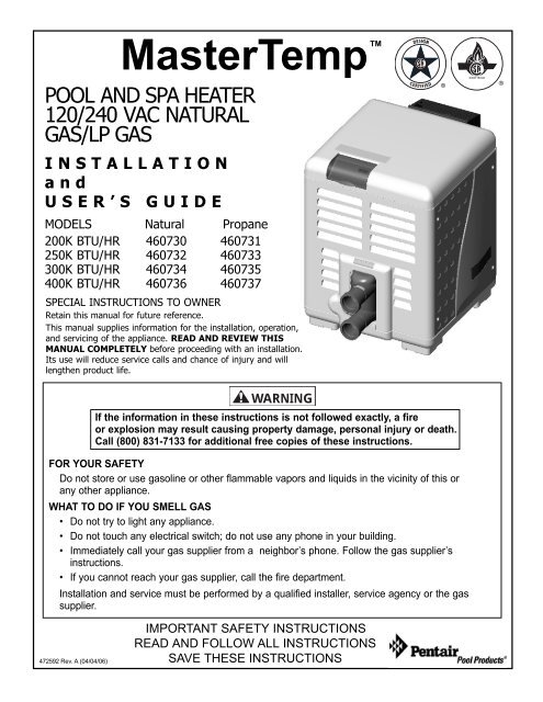
<strong>MasterTemp</strong>TM<br />
POOL AND SPA HEATER<br />
120/240 VAC NATURAL<br />
GAS/LP GAS<br />
®<br />
CERTIFIED<br />
®<br />
INSTALLATION<br />
<strong>and</strong><br />
USER’S GUIDE<br />
MODELS Natural Propane<br />
200K BTU/HR 460730 460731<br />
250K BTU/HR 460732 460733<br />
300K BTU/HR 460734 460735<br />
400K BTU/HR 460736 460737<br />
SPECIAL INSTRUCTIONS TO OWNER<br />
Retain this manual for future reference.<br />
This manual supplies information for the installation, operation,<br />
<strong>and</strong> servicing of the appliance. READ AND REVIEW THIS<br />
MANUAL COMPLETELY before proceeding with an installation.<br />
Its use will reduce service calls <strong>and</strong> chance of injury <strong>and</strong> will<br />
lengthen product life.<br />
WARNING<br />
If the information in these instructions is not followed exactly, a fire<br />
or explosion may result causing property damage, personal injury or death.<br />
Call (800) 831-7133 for additional free copies of these instructions.<br />
FOR YOUR SAFETY<br />
Do not store or use gasoline or other flammable vapors <strong>and</strong> liquids in the vicinity of this or<br />
any other appliance.<br />
WHAT TO DO IF YOU SMELL GAS<br />
• Do not try to light any appliance.<br />
• Do not touch any electrical switch; do not use any phone in your building.<br />
• Immediately call your gas supplier from a neighbor’s phone. Follow the gas supplier’s<br />
instructions.<br />
• If you cannot reach your gas supplier, call the fire department.<br />
Installation <strong>and</strong> service must be performed by a qualified installer, service agency or the gas<br />
supplier.<br />
472592 Rev. A (04/04/06)<br />
IMPORTANT SAFETY INSTRUCTIONS<br />
READ AND FOLLOW ALL INSTRUCTIONS<br />
SAVE THESE INSTRUCTIONS
INSTALLATION, OPERATION<br />
AND SERVICE MANUAL<br />
TO INSTALLER:<br />
Affix these instructions adjacent to the<br />
heater.<br />
TO CONSUMER:<br />
Retain these instructions for future reference.<br />
FOR YOUR SAFETY - This product must be installed<br />
<strong>and</strong> serviced by a professional service technician,<br />
qualified in pool heater installation. Improper installation<br />
<strong>and</strong>/or operation could create carbon monoxide gas <strong>and</strong><br />
flue gases which could cause serious injury or death.<br />
Improper installation <strong>and</strong>/or operation will void the<br />
warranty.<br />
Table of Contents<br />
Safety . . . . . . . . . . . . . . . . . . . . . . . . . . . . . . . . . . . 2<br />
General Specifications, Requirements . . . . . . . . . 3<br />
Description of the <strong>Heater</strong> . . . . . . . . . . . . . . . . . . . 4<br />
Sequence of Operation . . . . . . . . . . . . . . . . . . . . . 4<br />
Owner’s Operating Instructions . . . . . . . . . . . . . . 4<br />
Before Startup. . . . . . . . . . . . . . . . . . . . . . . . . . 4<br />
What To Do If You Smell Gas . . . . . . . . . . . . . . . 4<br />
Spa Temperature Caution . . . . . . . . . . . . . . . . . . 5<br />
Operating Instructions . . . . . . . . . . . . . . . . . . . . 5<br />
To Switch Off Gas To the Appliance . . . . . . . . . . . 6<br />
Operating Control . . . . . . . . . . . . . . . . . . . . . . . 6<br />
After Start-up . . . . . . . . . . . . . . . . . . . . . . . . . . 7<br />
Care/Maintenance/Winterizing. . . . . . . . . . . . . . . 8<br />
Installation Instructions . . . . . . . . . . . . . . . . . . . . 8<br />
Pre-Existing Vent Systems . . . . . . . . . . . . . . . . . 8<br />
Outdoor Installation . . . . . . . . . . . . . . . . . . . . . . 9<br />
Outdoor Shelter/Indoor Installation. . . . . . . . 10-15<br />
Water Connections . . . . . . . . . . . . . . . . . . . 15-18<br />
Pressure Relief Valve . . . . . . . . . . . . . . . . . . . . 18<br />
Checking Combination Gas Control Valve . . . . . . 19<br />
Gas Connections . . . . . . . . . . . . . . . . . . . . . . . 20<br />
Pressure Testing . . . . . . . . . . . . . . . . . . . . . . . 20<br />
Electrical Wiring . . . . . . . . . . . . . . . . . . . . . 20-22<br />
Troubleshooting . . . . . . . . . . . . . . . . . . . . . . . 23-30<br />
Repair Parts . . . . . . . . . . . . . . . . . . . . . . . . . . 31-35<br />
Wiring Diagrams/External Control Interface 36-37<br />
SAFETY INSTRUCTIONS<br />
FIGURE 1<br />
For instructions on checking the gas pressure<br />
through the Combination Gas Control Valve,<br />
See the sidebar on Page 19.<br />
FOR YOUR SAFETY - This product must be installed<br />
<strong>and</strong> serviced by a professional service technician,<br />
qualified in pool heater installation.<br />
Some jurisdictions require that installers be licensed.<br />
Check with your local building authority about contractor<br />
licensing requirements. Improper installation <strong>and</strong>/or<br />
operation could create carbon monoxide gas <strong>and</strong> flue<br />
gases which could cause serious injury or death.<br />
Improper installation <strong>and</strong>/or operation will void the<br />
warranty.<br />
CODES AND STANDARDS: Installation must be in<br />
accordance with all local codes <strong>and</strong>/or the latest edition<br />
of the National Fuel Gas Code, ANSI Z223.1/NFPA54 <strong>and</strong><br />
the National Electrical Code, ANSI/NFPA70 (U.S.), or<br />
st<strong>and</strong>ards CSA B149 – INSTALLATION CODES FOR GAS-<br />
BURNING APPLIANCES AND EQUIPMENT <strong>and</strong>/or local<br />
codes <strong>and</strong> St<strong>and</strong>ard CSA C22.1 – Canadian Electrical<br />
Code, Part 1 (Canada). The heater, when installed, must<br />
be electrically grounded <strong>and</strong> bonded in accordance with<br />
local codes, or, in absence of local codes, with the<br />
Canadian Electrical Code or the National Electrical Code,<br />
ANSI/NFPA70, as applicable.<br />
2
SAFETY INSTRUCTIONS (Continued)<br />
WARNING This appliance is equipped with an<br />
unconventional gas control valve that is factory<br />
set with a manifold pressure of -.2 inches wc.<br />
Improper installation, adjustment, alteration, service<br />
or maintenance can cause property damage,<br />
personal injury or loss of life. Installation or service<br />
must be performed by a qualified installer, service agency<br />
or the gas supplier. If this control is replaced, it must be<br />
replaced with an identical control.<br />
Do not attempt to adjust the gas flow by adjusting<br />
the regulator setting.<br />
WARNING Risk of fire or explosion from incorrect<br />
fuel use or faulty fuel conversion. Do not try to run a<br />
heater set up for natural gas on propane gas or vice<br />
versa. Only qualified service technicians should attempt<br />
to convert heater from one fuel to the other.<br />
Do not attempt to alter the rated input or type of gas by<br />
changing the orifice. If it is necessary to convert to a different<br />
type of gas, consult your Pentair dealer. Serious malfunction<br />
of the burner can occur which may result in loss of<br />
life. Any additions, changes, or conversions required in<br />
order for the appliance to satisfactorily meet the application<br />
needs must be made by a Pentair dealer or other qualified<br />
agency using factory specified <strong>and</strong> approved parts.<br />
The heater is available for use with natural gas or LP<br />
(propane) gas only. It is not designed to operate with any<br />
other fuels. Refer to the nameplate for the type of gas the<br />
heater is equipped to use.<br />
• Use heater only with the fuel for which it is designed.<br />
• If a fuel conversion is necessary, refer this work to a<br />
qualified service technician or gas supplier before<br />
putting the heater into operation.<br />
WARNING Risk of fire or explosion from flammable<br />
vapors. Do not store gasoline, cleaning fluids, varnishes,<br />
paints, or other volatile flammable liquids near<br />
heater or in the same room with heater.<br />
WARNING Risk of fire, carbon monoxide poisoning,<br />
or asphyxiation if exhaust venting system<br />
leaks. Only qualified service technicians should attempt<br />
to service the heater, as leakage of exhaust products or<br />
flammable gas may result from incorrect servicing.<br />
WARNING Risk of explosion if unit is installed<br />
near propane gas storage. Propane (LP) gas is heavier<br />
than air. Consult local codes <strong>and</strong> fire protection authorities<br />
about specific installation requirements <strong>and</strong> restrictions.<br />
Locate the heater away from propane gas storage <strong>and</strong> filling<br />
equipment as specified by the St<strong>and</strong>ard for the<br />
Storage <strong>and</strong> H<strong>and</strong>ling of Liquefied Petroleum Gases,<br />
CAN/CSA B149.2 (latest edition) or ANSI/NFPA 58 (latest<br />
edition).<br />
WARNING Risk of asphyxiation if exhaust is not<br />
correctly vented. Follow venting instructions<br />
exactly when installing heater. Do not use a draft<br />
hood with this heater, as the exhaust is under pressure<br />
from the burner blower <strong>and</strong> a draft hood will allow<br />
exhaust fumes to blow into the room housing the heater.<br />
The heater is supplied with an integral venting system for<br />
outdoor installation. A vent conversion kit (See Page 14<br />
for Part Numbers for Conversion Kits) is available for<br />
installations in enclosures (Canada) or indoors (U.S.). Use<br />
the specified venting, <strong>and</strong> only the specified venting,<br />
when heater is installed in an enclosure or indoors. In<br />
Canada, this pool heater can only be installed outdoors<br />
or in an enclosure that is not normally occupied <strong>and</strong> has<br />
no openings directly into occupied areas. See Page 11 for<br />
enclosure venting requirements.<br />
CAUTION Label all wires prior to disconnection<br />
when servicing controls. Wiring errors can cause<br />
improper <strong>and</strong> dangerous operation. Wiring errors<br />
can also destroy the control board.<br />
Connect heater to 120 or 240 Volt, 60 Hz., 1 Phase<br />
power only.<br />
Verify proper operation after servicing.<br />
Do not allow children to play on or around heater or<br />
associated equipment.<br />
Never allow children to use the pool or spa without adult<br />
supervision.<br />
Read <strong>and</strong> follow other safety information contained in<br />
this manual prior to operating this pool heater.<br />
GENERAL SPECIFICATIONS/<br />
REQUIREMENTS<br />
NOTICE: Combustion air contaminated by corrosive<br />
chemical fumes can damage the heater <strong>and</strong> will void the<br />
warranty.<br />
NOTICE: The Combination Gas Control Valve on this<br />
appliance differs from most appliance gas controls. If it<br />
must be replaced, for safety reasons replace it only with<br />
an identical gas control.<br />
NOTICE: The access door panels must be in place to<br />
provide proper ventilation. Do not operate the heater for<br />
more than five (5) minutes with the access door panels<br />
removed.<br />
This heater is design certified by CSA International as<br />
<strong>com</strong>plying with the St<strong>and</strong>ard for Gas Fired Pool <strong>Heater</strong>s,<br />
ANSI Z21.56/CSA 4.7, <strong>and</strong> is intended for use in heating<br />
fresh water swimming pools or spas.<br />
NOTICE: Do not use this heater as a heating boiler,<br />
water heater, or for heating salt-water pools. This heater<br />
is intended for use in heating fresh water swimming<br />
pools or spas only. The heater requires an external 120<br />
or 240 VAC single-phase electric power source.<br />
The heater is design certified by CSA International for<br />
installation on <strong>com</strong>bustible flooring. Specified minimum<br />
clearances must be maintained to <strong>com</strong>bustible surfaces<br />
(see “Installation Instructions”, Pages 8 <strong>and</strong> 9).<br />
The heater should be located in an area where leakage<br />
of the heater or connections will not result in damage to<br />
the area adjacent to the heater or to the structure. When<br />
such locations cannot be avoided, it is re<strong>com</strong>mended that<br />
a suitable drain pan, adequately drained, be installed<br />
under the heater. The pan must not restrict air flow.<br />
3
The heater may not be installed within five feet of the<br />
inside surface of a pool or spa unless it is separated by a<br />
solid fence, wall or other permanent barrier.<br />
A Propane (LPG) fired heater must not be installed in a<br />
garage in Massachusetts, by order of the Massachusetts<br />
State Fire Marshall. For more information, call the Fire<br />
Marshall’s office.<br />
DESCRIPTION OF THE HEATER<br />
Inlet<br />
(Cold<br />
Water)<br />
Outlet<br />
(Mixed<br />
Water)<br />
Air<br />
FIGURE 2<br />
Mixer<br />
Gas<br />
Burner<br />
Blower<br />
Figure 2 is a diagram of the heater showing how it operates.<br />
Precisely matched orifice plates meter the air <strong>and</strong> gas<br />
into the mixer. The blower draws the air <strong>and</strong> gas through<br />
the mixer <strong>and</strong> forces it into the burner’s flameholder. A<br />
sealed heat exchanger surrounds the flameholder, discharging<br />
exhaust gases out the flue.<br />
Two inch PVC water piping connects directly to the<br />
manifold/header on the heat exchanger using 2" PVC slip<br />
unions provided with the heater. The outer manifold<br />
remains cool; no heat sinks are required. A thermal<br />
regulator <strong>and</strong> an internal bypass regulate the water flow<br />
through the heat exchanger to maintain the correct outlet<br />
temperature. The heater operator control panel board<br />
assembly is located on top of the heater.<br />
SEQUENCE OF OPERATION<br />
An electronic temperature sensing thermistor in the<br />
manifold adapter inlet controls the heater operation.<br />
When the inlet water temperature drops below the<br />
temperature set on the operating control, the burner<br />
controller supplies power to the <strong>com</strong>bustion air blower<br />
through a series of safety interlocks. The interlocks<br />
consist of<br />
• the pressure switch (PS), which senses that the pump<br />
is running,<br />
Exhaust<br />
Heating Coils<br />
• the high limit switch (HLS), which opens if the heat<br />
exchanger outlet temperature goes above 135° F<br />
(57° C), <strong>and</strong><br />
• the automatic gas shutoff (AGS) switch, which opens<br />
if the heat exchanger outlet temperature goes above<br />
140° F (60° C).<br />
• the stack flue sensor (SFS), which shuts down the<br />
heater if the flue gas temperature reaches 500° F<br />
(260° C).<br />
The air flow switch (AFS) senses the pressure drop<br />
across the air metering orifice. As soon as there is sufficient<br />
air flow, the AFS closes, closing the circuit to the<br />
hot surface igniter (HSI), which ignites the fuel mixture.<br />
On a call for heat, the blower <strong>and</strong> HSI are energized. In<br />
about 20 seconds, the gas valve opens <strong>and</strong> ignition<br />
occurs. The HSI then switches to a sensing mode <strong>and</strong><br />
monitors the flame.<br />
The heater is equipped with a digital operating control<br />
that enables the user to pre-set the desired pool <strong>and</strong> spa<br />
water temperatures. The control enables the user to<br />
select between pool <strong>and</strong> spa heating, <strong>and</strong> features a<br />
digital display that indicates the water temperature.<br />
OWNER’S OPERATING<br />
INSTRUCTIONS<br />
FOR YOUR SAFETY READ BEFORE OPERATING<br />
WARNING IF YOU DO NOT FOLLOW THESE<br />
INSTRUCTIONS EXACTLY, A FIRE OR EXPLOSION<br />
MAY RESULT, CAUSING PROPERTY DAMAGE,<br />
PERSONAL INJURY OR LOSS OF LIFE.<br />
START-UP AND OPERATION<br />
START-UP AND SHUTDOWN INSTRUCTIONS ARE ON THE<br />
LABEL ATTACHED TO THE COVER OF THE APPLIANCE<br />
CONTROL BOX.<br />
BEFORE START-UP<br />
A. This appliance does not have a pilot. It is equipped<br />
with an ignition device which automatically lights the<br />
burner. Do not try to light the burner by h<strong>and</strong>.<br />
B. BEFORE OPERATING check for odor. Sniff all around<br />
the appliance area for gas. Be sure to sniff next to<br />
the floor, because some gas (such as propane) is<br />
heavier than air <strong>and</strong> will settle on the floor.<br />
WHAT TO DO IF YOU SMELL GAS<br />
• Do not try to light any appliance.<br />
• Do not touch any electrical switch; do not use any<br />
phone in your building.<br />
• Immediately call your gas supplier from a<br />
neighbor’s phone. Follow the gas supplier’s<br />
instructions.<br />
• If you cannot reach your gas supplier, call the fire<br />
department.<br />
4
C. Use only your h<strong>and</strong> to turn the gas control on or off.<br />
Never use tools. If you cannot change the ON/OFF<br />
setting by h<strong>and</strong>, don’t try to repair it, call a qualified<br />
service technician. Force or attempted repair may<br />
result in fire or explosion.<br />
D. Do not use this heater if any part has been under<br />
water. Immediately call a qualified service technician<br />
to inspect the heater <strong>and</strong> to replace any part of the<br />
control system <strong>and</strong> any gas control which has been<br />
under water.<br />
E. Do not operate the pool heater unless the pool or<br />
spa is properly filled with water.<br />
F. Before operating the appliance for the first time or<br />
after it has been off for an extended time, perform<br />
the following checklist:<br />
1. Remove debris or other articles from inside the<br />
heater <strong>and</strong> the area around the heater <strong>and</strong> its<br />
exhaust vent. Make sure the ventilation openings<br />
are clear of debris or obstruction. For installations<br />
in an enclosed space, make sure openings for<br />
<strong>com</strong>bustion <strong>and</strong> ventilation air are unobstructed.<br />
2. Keep heater area clear <strong>and</strong> free from <strong>com</strong>bustibles,<br />
flammable liquids <strong>and</strong> chemicals.<br />
3. Check that all water connections are tight.<br />
4. Water must be flowing through the heater during<br />
operation. Make sure that pool/spa is filled with<br />
water <strong>and</strong> have pump operating. Check that water<br />
flow is unobstructed from the appliance. When<br />
operating for the first time or after an extended<br />
shut-down, run filter pump for several minutes to<br />
clear all air from the system.<br />
SPA TEMPERATURE CAUTION<br />
All safety rules re<strong>com</strong>mended by the U.S. Consumer<br />
Product Safety Commission should be observed when<br />
using a spa or hot tub, including:<br />
1. Spa or hot tub water temperatures should never<br />
exceed 104° F (40° C). A temperature of 100°F<br />
(38°C) is considered safe for a healthy adult. Special<br />
caution is suggested for young children.<br />
2. Drinking of alcoholic beverages before or during spa<br />
or hot tub use can cause drowsiness which could<br />
lead to unconsciousness <strong>and</strong> subsequently result in<br />
drowning.<br />
3. Pregnant women beware! Soaking in water above<br />
102° F (39° C) can cause fetal damage during the<br />
first three months of pregnancy (resulting in the birth<br />
of a brain-damaged or deformed child). Pregnant<br />
women should follow the 100° F (38° C) maximum<br />
rule.<br />
4. Before entering the spa or hot tub, users should<br />
check the water temperature with an accurate<br />
thermometer; spa or hot tub thermostats may err in<br />
regulating water temperature.<br />
5. Persons with medical history of heart disease, circulatory<br />
problems, diabetes or blood pressure problems<br />
should obtain their physician’s advice before using<br />
spas or hot tubs.<br />
6. Persons taking medications which induce drowsiness,<br />
such as tranquilizers, antihistamines or<br />
anticoagulants, should not use spas or hot tubs.<br />
OPERATING INSTRUCTIONS<br />
1. STOP! Read the safety information above.<br />
2. Set both pool <strong>and</strong> spa thermostats to the lowest<br />
settings.<br />
3. Turn off all electric power to the appliance.<br />
4. This appliance does not have a pilot. It is equipped<br />
with an ignition device which automatically lights the<br />
burner. Do not try to light the burner by h<strong>and</strong>.<br />
FIGURE 3: Removal of Access Door Panels<br />
5. Remove the access door panels by unfastening the<br />
four 1/4-20 phillips head screws located on each<br />
door, then lift up <strong>and</strong> out from the bottom of the<br />
panel to remove. If necessary, the screws may be<br />
used as h<strong>and</strong>les. See Figure 3.<br />
6. Toggle-Style Valve: Pull toggle toward you to turn gas<br />
off.<br />
7. Wait five (5) minutes to clear out any gas. If you<br />
then smell gas, STOP! Follow “B” in the “Before<br />
Startup” instructions (Page 4). If you don’t smell gas,<br />
go to the next step.<br />
You are<br />
here<br />
Gas control is shown<br />
ON. Pull toggle switch<br />
toward you to switch<br />
OFF<br />
FIGURE 4: Turning Gas Control OFF<br />
5
8. Push the toggle switch away from you to switch the<br />
gas on.<br />
9. Replace the Door Access Panels. All panels must be<br />
in place when operating the heater.<br />
10. Set 3-way valves on inlet <strong>and</strong> outlet to pool or spa,<br />
as appropriate.<br />
11. Turn on all electric power to the appliance.<br />
12. Press either the POOL ON or SPA ON button switch<br />
on the operating control.<br />
You are<br />
here<br />
Gas control is shown<br />
OFF. Push toggle<br />
switch away from you<br />
to switch ON.<br />
4. Toggle-Style Valve: Pull toggle toward you to turn gas<br />
off.<br />
5. Replace the Access Door Panels.<br />
OPERATING CONTROL<br />
The five operating switches are:<br />
POOL ON Press this button to govern heater operation<br />
by the pool temperature setting.<br />
SPA ON Press this button to govern heater operation by<br />
the spa temperature setting.<br />
HEATER OFF Press this button to switch off the heater.<br />
▲ TEMP Press this button to raise the temperature<br />
setting.<br />
▼ TEMP Press this button to lower the temperature<br />
setting.<br />
To toggle the display between degrees Centigrade (°C)<br />
<strong>and</strong> degrees Fahrenheit (°F):<br />
1. Turn the Operating Control OFF.<br />
2. Press ▲ TEMP or ▼ TEMP for 5 seconds. The display<br />
will flash once <strong>and</strong> change modes (°C to °F or<br />
vice versa).<br />
Temperature<br />
Up <strong>and</strong> Down<br />
Digital Temperature<br />
Display<br />
FIGURE 5: Turning Gas Control ON<br />
13. Set the thermostat to desired setting (NOTICE: Set<br />
point must be above actual water temperature or<br />
burner will not fire). See “OPERATING CONTROL.”<br />
14. The blower should <strong>com</strong>e on immediately, <strong>and</strong> after<br />
about 20 seconds, the burner should fire. When<br />
operating for the first time, the burner may not fire<br />
on the first try because of air in the gas line. If it<br />
does not fire at first, push the OFF switch, wait five<br />
minutes, <strong>and</strong> again push the POOL or SPA ON switch.<br />
The burner should fire after about 20 seconds. You<br />
may have to repeat this until all of the air has cleared<br />
the gas line.<br />
15. The burner should fire until the pool/spa temperature<br />
reaches the desired temperature set on the thermostat.<br />
The blower will continue to run for about 45<br />
seconds after the burner shuts off. If any of the<br />
safety interlocks should open during burner operation,<br />
the burner shuts off immediately, but the blower<br />
continues to run for about 45 seconds.<br />
Should overheating occur or the gas supply fail to<br />
shut off, turn off the manual gas control valve to the<br />
appliance.<br />
16. If the appliance will not operate, follow the instructions<br />
“TO SWITCH OFF GAS TO THE APPLIANCE”,<br />
<strong>and</strong> call your service technician or gas supplier.<br />
TO SWITCH OFF GAS TO THE APPLIANCE<br />
1. Press the OFF button on operating control.<br />
2. Switch off all electric power to the unit.<br />
3. Remove the access door panels.<br />
See Figure 3, page 5.<br />
WARNING HEATER PARTS MAY BE HOT.<br />
System Operation<br />
Indicator Lights<br />
Dual Temperature<br />
Controls<br />
FIGURE 6: Operating Control for all models.<br />
<strong>Heater</strong> OFF<br />
Switch<br />
When either the ▲ TEMP or ▼ TEMP buttons are<br />
depressed, the digital display will indicate the temperature<br />
setting. After five seconds, the display will return to<br />
the actual pool/spa temperature.<br />
In addition to the digital temperature display, there are<br />
five indicator lights:<br />
The POOL ON light indicates that the pool water temperature<br />
is governing operation of the heater.<br />
The SPA ON light indicates that the spa water temperature<br />
is governing operation of the heater.<br />
The HEATING light <strong>com</strong>es on <strong>and</strong> stays on when the<br />
burner is firing. This light should be on whenever the<br />
burner is on. It blinks when the heater is calling for heat<br />
but not firing. If this light is on but the burner fails to<br />
<strong>com</strong>e on, one of the “service” lights should <strong>com</strong>e on,<br />
indicating a fault in the system.<br />
6
The SERVICE SYSTEM light indicates that there is<br />
insufficient water flow to the heater. If the pump is operating,<br />
this usually indicates that the filter <strong>and</strong>/or skimmers<br />
should be cleaned (some filters may require backwashing).<br />
If the light remains on after the filter/skimmers<br />
have been serviced, the system should be checked by a<br />
qualified service technician.<br />
The SERVICE HEATER light indicates a fault in the<br />
heater or its controls. If this light <strong>com</strong>es on, shut down<br />
the heater (See TO SWITCH OFF GAS TO THE<br />
APPLIANCE on page 6), <strong>and</strong> have a qualified service<br />
technician check the system.<br />
WARNING Risk of explosion or fire causing burns or<br />
death if safety interlocks are disabled. DO NOT attempt<br />
to operate heater when SERVICE HEATER light is on or if<br />
blower or burner will not start. Instead, follow instructions<br />
under “To Switch Off Gas to the Appliance,” <strong>and</strong> call<br />
a qualified service technician to repair unit.<br />
AFTER START-UP<br />
CHECKING WATER FLOW<br />
WARNING Fire or flooding hazard. If the unit overheats<br />
<strong>and</strong> the burner fails to shut off, follow instructions under<br />
“To Switch Off Gas to the Appliance”, Page 6, <strong>and</strong> call a<br />
qualified service technician to repair unit.<br />
After start-up, the outlet water pipe should feel slightly<br />
warmer than the inlet pipe. If it feels hot, or if you hear<br />
the water in the heater boiling, there may not be enough<br />
water flow to the appliance. Make sure that the filter is<br />
not plugged. If water temperature remains high but the<br />
unit continues to operate, turn off the appliance <strong>and</strong> call<br />
your service technician.<br />
SPRING AND FALL OPERATION<br />
If the pool is only used occasionally, lower the pool thermostat<br />
to 65° F (18° C). <strong>and</strong> leave the heater on. This<br />
will keep the pool <strong>and</strong> the surrounding ground warm<br />
enough so that the heater should restore the pool to a<br />
<strong>com</strong>fortable temperature within about one day.<br />
COLD WEATHER OPERATION<br />
The heater may be operated in the wintertime, provided<br />
air temperatures remain above freezing <strong>and</strong> the water<br />
temperature is not permitted to drop below 65° F (18°<br />
C). Extended heater operation with water temperatures<br />
below 65° F (10° C) can result in serious damage to the<br />
heater <strong>and</strong> is not covered by warranty.<br />
NOTICE: When starting the heater for the swimming season<br />
with a water temperature below 50° F (10° C), the<br />
heater may be used to heat the water; however, make<br />
sure that the heater operates continuously until the water<br />
temperature reaches the heater’s minimum setting of 65°<br />
F (18° C).<br />
DO NOT operate this unit outdoors at temperatures<br />
below 40° F (4° C).<br />
During cold weather, if there is no danger of freezing,<br />
operate the filter pump continuously even if the heater is<br />
not operating. If air temperatures are expected to drop<br />
below freezing (32° F/0° C), shut down the heater <strong>and</strong><br />
winterize it (See ”WINTERIZING”, Page 8). Allowing the<br />
heater to freeze will void the warranty.<br />
MAINTAINING POOL TEMPERATURE<br />
To maintain pool temperature, make sure that the heater<br />
switch <strong>and</strong> valving are reset to pool settings after using<br />
the spa.<br />
ENERGY SAVING TIPS<br />
1. Keep the pool or spa covered when not in use. This<br />
will reduce heating costs, reduce water evaporation,<br />
conserve chemicals <strong>and</strong> reduce load on the filtering<br />
system.<br />
2. Reduce pool thermostat to 78° F (25° C) or lower;<br />
reduce spa temperature to 100° F (38° C).<br />
3. Use a time clock to start the filter pump at 6 a.m. or<br />
later. The swimming pool loses less heat after daybreak.<br />
4. For pools used only on weekends, lower the thermostat<br />
setting by 10° F to 15° F (5° C to 8° C) during<br />
the week to reduce heat loss. A properly sized heater<br />
will restore normal temperature within one day.<br />
5. Turn the heater off when the pool will not be used<br />
for an extended period.<br />
6. Follow a regular program of preventive maintenance<br />
for the heater each new swimming season. Check<br />
operation of the heater <strong>and</strong> its controls.<br />
7
CARE AND MAINTENANCE<br />
MAINTENANCE INSTRUCTIONS<br />
WARNING Risk of fire or explosion from flammable<br />
vapors. Do not store gasoline, cleaning fluids, varnishes,<br />
paints, or other volatile flammable liquids near heater or<br />
in the same room with heater.<br />
The following maintenance is re<strong>com</strong>mended every six<br />
months <strong>and</strong> at the start of every swimming season:<br />
1. Inspect the heater panels <strong>and</strong> venting system to<br />
make sure that there are no obstructions to the flow<br />
of ventilating air or burner exhaust. Check that room<br />
air intakes are open <strong>and</strong> clear of obstructions.<br />
2. Keep the area in <strong>and</strong> around the heater clear <strong>and</strong><br />
free from <strong>com</strong>bustible materials, gasoline <strong>and</strong> other<br />
flammable vapors <strong>and</strong> corrosive liquids.<br />
3. Test the operation of the pressure relief valve by lifting<br />
the valve lever.<br />
4. Test for proper operation of the pressure switch. (See<br />
“SWITCH SETTINGS” for testing instructions).<br />
5. On enclosed installations with high-temperature<br />
Special Gas Vent systems, repeat the “Final<br />
Installation Check,” page 15. Check for evidence of<br />
joint leakage. Make sure that joints have not slipped<br />
partially or <strong>com</strong>pletely apart. Check pipe <strong>and</strong> fittings<br />
for cracks or breaks.<br />
The <strong>com</strong>bustion air blower is permanently lubricated, <strong>and</strong><br />
does not require periodic lubrication. The burner does not<br />
require maintenance or adjustment by the user. Call a<br />
qualified service technician if you suspect that the burner<br />
may require maintenance.<br />
WINTERIZING<br />
For outdoor heaters in freezing climates, shut the heater<br />
down <strong>and</strong> drain it for winter as follows:<br />
1. Turn off electrical supply to the heater <strong>and</strong> pump.<br />
2. Close main gas control valve <strong>and</strong> manual gas valve<br />
(located outside the heater). Turn switch on heater<br />
gas valve to OFF.<br />
3. Open drain cock located on the bottom of the manifold<br />
adapter, <strong>and</strong> drain the heat exchanger <strong>and</strong> manifold<br />
adapter <strong>com</strong>pletely. If heater is below pool water level,<br />
be sure to close isolation valves to prevent draining<br />
the pool (isolation valves are not required <strong>and</strong> should<br />
not be used on heaters installed above pool water<br />
level). Assist the draining by blowing out the heat<br />
exchanger through the pressure switch fitting with low<br />
pressure <strong>com</strong>pressed air (less than 5 PSI or 35 kPa).<br />
WARNING Explosion hazard. Purging the system with<br />
<strong>com</strong>pressed air can cause <strong>com</strong>ponents to explode, with<br />
risk of severe injury or death to anyone nearby. Use only<br />
a low pressure (below 5 PSI or 35 kPa), high volume<br />
blower when air purging the heater, pump, filter, or piping.<br />
4. Remove the Water Pressure Switch. Plug the port in<br />
the manifold to prevent bugs <strong>and</strong> dirt from getting<br />
into the manifold.<br />
5. Drain the plastic inlet/outlet manifold through the<br />
outlet pipe. If the pipe does not drain naturally to the<br />
pool, install a drain cock in the outlet pipe to drain<br />
the manifold.<br />
6. Cover air inlet grate with a plastic bag to prevent<br />
bugs, leaves, etc., from getting into the heater.<br />
NOTICE: Water trapped in the heater can cause freeze<br />
damage. Allowing the heater to freeze voids the<br />
warranty.<br />
To return the heater to service after winterizing:<br />
1. Close drain cock <strong>and</strong> fittings.<br />
2. Before starting the heater, circulate water through<br />
the heater for several minutes until all air noises<br />
stop. See also “BEFORE STARTUP” (Page 4) <strong>and</strong><br />
“CARE AND MAINTENANCE” (above).<br />
INSTALLATION INSTRUCTIONS<br />
WARNING Risk of fire, explosion, or asphyxiation if heater<br />
is improperly installed, adjusted, serviced or maintained.<br />
These instructions are for licensed, certified, trained <strong>and</strong><br />
experienced installers only. Be sure your installer or service<br />
technician holds all required licenses or certification<br />
for your area. Attempts by unqualified persons to service<br />
or repair this heater are dangerous <strong>and</strong> could be fatal.<br />
PRE-EXISTING VENT SYSTEMS<br />
If you are considering connecting this heater to a pre-existing<br />
vent system, make sure that the vent system meets the<br />
appropriate venting requirements as given in this manual,<br />
Pages 9-15. If not, replace the vent system. DO NOT use a<br />
draft hood with this heater.<br />
PUTTING THE HEATER INTO SERVICE<br />
If the heater is installed below the level of the pool, or<br />
more than two feet above pool level, the pressure switch<br />
setting should be adjusted. See PRESSURE SWITCH, in<br />
the MAINTENANCE section.<br />
Before putting the heater into service for the first time,<br />
follow the instructions under “BEFORE START-UP” (page<br />
4) in the front of this manual. Check for proper operation<br />
of the heater by following the steps under “OPERATING<br />
INSTRUCTIONS.”<br />
Damage to equipment caused by improper installation or<br />
repair will void the warranty.<br />
8
OUTDOOR INSTALLATION INSTRUCTIONS<br />
For heaters located outdoors, using the built-in stackless<br />
venting system.<br />
WARNING Risk of explosion if a unit burning propane<br />
gas is installed in a pit or other low spot. Propane is heavier<br />
than air. Do not install the heater using propane in pits<br />
or other locations where gas might collect. Consult your<br />
local building code officials to determine installation requirements<br />
of heater relative to propane storage tanks <strong>and</strong> filling<br />
equipment. Installation must meet the requirements of<br />
the St<strong>and</strong>ard for the Storage <strong>and</strong> H<strong>and</strong>ling of Liquid<br />
Petroleum Gases, ANSI/NFPA 58 (latest edition) in the U.S., or<br />
CAN/CSA B149.2 (latest edition) in Canada. Consult local codes<br />
<strong>and</strong> fire protection authorities about specific installation restrictions.<br />
Locate the heater on a level surface in an open area that<br />
is protected from drainage or run-off. Install the heater in<br />
an area where leaves or other debris will not collect on<br />
or around the heater.<br />
This heater is designed for outdoor installation. However,<br />
to avoid damage to the electronic <strong>com</strong>ponents in the<br />
heater, take care to prevent prolonged exposure to driving<br />
sources of water (such as lawn sprinklers, heavy<br />
roof runoff, hoses, etc.). Avoid operation in persistent,<br />
extreme, moist or salty environments.<br />
In extreme weather, shut down the heater <strong>and</strong> disconnect<br />
the power to it until the weather has moderated. In<br />
areas subject to hurricanes or very high winds, purchase<br />
the Bolt Down Bracket Kit, Part No. 460738.<br />
HEATER CLEARANCES – OUTDOOR<br />
In the U.S.: If the heater is located under a roof or<br />
deck overhang, there must be at least three feet (1M) of<br />
clearance between the bottom of the overhang <strong>and</strong> the<br />
top of the heater exhaust vent. If the heater is under a<br />
roof or deck overhang, the space around the heater must<br />
be open on three sides. See Figure 8 for minimum clearances.<br />
For minimum exhaust vent clearances for building openings,<br />
see Figure 13, Page 15.<br />
In Canada: If the heater is located under a roof or deck<br />
overhang, there must be at least three feet (1M) of clearance<br />
between the bottom of the overhang <strong>and</strong> the top of<br />
the heater exhaust vent. If the heater is under a roof or<br />
deck overhang, the space around the heater must be<br />
open on three sides. See Figure 8 for minimum clearances.<br />
The heater must be installed with the top of the vent at<br />
least 10 feet (3M) below, or to either side of, any opening<br />
into a building.<br />
In the U.S. <strong>and</strong> Canada: The heater is certified for installation<br />
on <strong>com</strong>bustible flooring.<br />
The following clearances must be maintained from<br />
<strong>com</strong>bustible surfaces:<br />
TOP ...................................3 ft. (1 m)<br />
EXHAUST SIDE................6 in. (15 cm)<br />
HEADER SIDE..................18 in. (.5 m)<br />
DOOR PANELS* ............12 in. (30 cm)<br />
Note (*) For service access it is re<strong>com</strong>mended to leave<br />
at least 24 in. clearance for one of the door panels.<br />
Orient the heater for convenient access to the water<br />
connections <strong>and</strong> the gas <strong>and</strong> electrical connections.<br />
Install the heater at least 18 in. (45 cm) from any<br />
property line.<br />
Space around<br />
the heater<br />
must open on<br />
three sides<br />
when under<br />
roof or<br />
overhang<br />
3 ft. (1 M) or more<br />
(*) Re<strong>com</strong>mended ended 24" clearance or more on one<br />
or both door panels for servicing<br />
12 in.*<br />
Outdoor installation must<br />
have at leave 3 ft. or more<br />
of clearance above heater<br />
Leave at least 6 in. (15 cm) of clearance or more<br />
between the heater <strong>and</strong> <strong>com</strong>bustible surfaces<br />
FIGURE 8: Combustible clearances<br />
18 in.<br />
12 in.*<br />
6 in.<br />
9
CONTROL PANEL INDEXING<br />
The exhaust discharges vertically from outside the vent<br />
cover. The heater control panel assembly located on the<br />
top panel can be rotated to any of three positions for<br />
convenient access to the panel as follows:<br />
1. Remove the bolts from the door panels. Remove both<br />
door panels.<br />
2. Remove the four corner screws that secure the top<br />
panel.<br />
3. Lift the top panel upward to remove the top panel.<br />
4. Rotate the top panel to the desired position located<br />
at 90 degree angles. Note that the control board cannot<br />
be located on the same side as the exhaust.<br />
5. Replace the top panel down onto the side panels. Be<br />
sure that there are no wires caught under the panel.<br />
6. Secure the top panel using the four corner screws.<br />
7. Reattach the door access panels.<br />
OUTDOOR SHELTER<br />
Top panel<br />
Door<br />
access<br />
panel<br />
protection authorities about specific installation restrictions.<br />
The heater is design certified by CSA International for<br />
installation on <strong>com</strong>bustible flooring; in alcoves; basements;<br />
in closet or utility rooms (in the U.S.)<br />
INSTALLATION IN A GARAGE OR UTILITY ROOM<br />
In Canada, the heater must be installed in a room that is<br />
not normally occupied <strong>and</strong> has no openings directly to<br />
occupied areas.<br />
WARNING Risk of fire <strong>and</strong> explosion if installed at floor<br />
level in an automotive garage or near gasoline or flammable<br />
liquid storage. Gasoline fumes are heavier than air<br />
<strong>and</strong> will settle to floor level in closed spaces. Gasoline<br />
fumes <strong>and</strong> spilled gasoline or other volatile liquids (such<br />
as some paints <strong>and</strong> varnishes) will travel across the floor<br />
<strong>and</strong> can be ignited by a gas appliance. In a utility room<br />
or residential garage installation, install the heater with<br />
the base at least 18 inches (.5M) above the floor. In a<br />
garage, install a rail or wall to protect the heater from<br />
physical damage by a moving vehicle.<br />
Provide an adequate ventilation air supply (See Table 2,<br />
Page 11). Choose a location that will avoid contamination<br />
by chemical fumes.<br />
NOTICE: A PROPANE (LPG) fired heater must not be<br />
installed in a garage in Massachusetts, by order of the<br />
Massachusetts State Fire Marshall. For more information,<br />
call the State Fire Marshall’s office.<br />
Door access<br />
panel<br />
HEATER INSTALLATION IN A<br />
GARAGE OR UTILITY ROOM<br />
FIGURE 9: Indexing Control Panel<br />
INSTALLATION INSTRUCTIONS<br />
This pool heater can only be installed outdoors or in an<br />
enclosure that is not normally occupied <strong>and</strong> has no direct<br />
openings into occupied areas.<br />
Leave 3 ft. (1 M) or<br />
more of clearance<br />
above heater<br />
WARNING Risk of asphyxiation if exhaust is not correctly<br />
vented. Follow venting instructions exactly when<br />
installing heater. Do not use a draft hood with this heater,<br />
as the exhaust is under pressure from the burner blower<br />
<strong>and</strong> a draft hood will allow exhaust fumes to blow into<br />
the room housing the heater. Exhaust venting to the outdoors<br />
is required for all outdoor shelter installations.<br />
WARNING Risk of explosion if a unit burning propane<br />
gas is installed in a pit or other low spot. Propane is heavier<br />
than air. Do not install the heater using propane in pits<br />
or other locations where gas might collect. Consult your<br />
local building code officials to determine installation requirements<br />
of heater relative to propane storage tanks <strong>and</strong> filling<br />
equipment. Installation must meet the requirements for<br />
the St<strong>and</strong>ard for the Storage <strong>and</strong> H<strong>and</strong>ling of Liquefied<br />
Petroleum Gases, CAN/CSA B149.2 (latest edition) or<br />
ANSI/NFPA 58 (latest edition). Consult local codes <strong>and</strong> fire<br />
Leave 6 in. (15cm)<br />
of clear space<br />
between heater<br />
<strong>and</strong> <strong>com</strong>bustible<br />
surface<br />
RAISE AT LEAST<br />
18 in. (.5M) above<br />
floor to avoid<br />
flammable vapors<br />
18 in.<br />
FIGURE 10: Minimum outdoor shelter clearances (Canada)<br />
or minimum garage or utility room clearances (U.S.)<br />
10
NOTICE: Combustion air contaminated by corrosive<br />
chemical fumes can damage the heater <strong>and</strong> will void the<br />
warranty (See Table 1 below).<br />
HEATER CLEARANCES –<br />
OUTDOOR SHELTER (Canada) or INDOOR (U.S.)<br />
The following clearances must be maintained from <strong>com</strong>bustible<br />
surfaces:<br />
TOP......................................3 ft. (1 m)<br />
EXHAUST SIDE ................6 in. (15 cm)<br />
HEADER SIDE...................18 in. (.5 m)<br />
DOOR PANELS* .............12 in. (30 cm)<br />
Note (*) For service access it is re<strong>com</strong>mended to leave at<br />
least 24 in. clearance for one of the door panels.<br />
The heater is design certified by CSA International for<br />
installation on <strong>com</strong>bustible flooring. For installation on<br />
carpeting, the heater must be mounted on a metal or<br />
wood panel that extends at least three inches (10cm)<br />
beyond the base of the heater. If the heater is installed<br />
in a closet or alcove, the entire floor shall be covered by<br />
the panel. On an outdoor shelter installation, the exhaust<br />
discharges into a vent pipe. Orient the heater so that the<br />
vent pipe does not interfere with adjustment of the operating<br />
controls. The control panel located on the top panel can<br />
be rotated to any of the three sides of the heater for easy<br />
access. However, the control panel must not be located on<br />
the side where the vent is located.<br />
Table 1: Corrosive Vapors <strong>and</strong> Possible Causes<br />
Area<br />
Chlorinated swimming<br />
pools <strong>and</strong> spas<br />
New construction <strong>and</strong><br />
remodeling areas<br />
Beauty parlors<br />
Refrigeration plants or<br />
various industrial<br />
finishing <strong>and</strong> processing<br />
plants<br />
Dry cleaning <strong>and</strong><br />
laundry areas<br />
Likely Contaminants<br />
Pool or spa cleaning<br />
chemicals. Acids, such as<br />
hydrochloric or muriatic acid<br />
Glues <strong>and</strong> cements,<br />
construction adhesives,<br />
paints, varnishes, <strong>and</strong><br />
paint <strong>and</strong> varnish strippers.<br />
Waxes <strong>and</strong> cleaners<br />
containing calcium or<br />
sodium chloride<br />
Permanent wave solutions,<br />
bleaches, aerosol cans<br />
containing chlorocarbons<br />
or fluorocarbons<br />
Refrigerants, acids, glues<br />
<strong>and</strong> cements, construction<br />
adhesives<br />
Bleaches, detergents, or<br />
laundry soaps containing<br />
chlorine.<br />
Waxes <strong>and</strong> cleaners<br />
containing chlorine,<br />
calcium or sodium chloride<br />
COMBUSTION AND VENTILATION AIR SUPPLY<br />
For shelter installation, the heater requires air supply openings<br />
for ventilation <strong>and</strong> <strong>com</strong>bustion. The minimum requirements<br />
are for two (2) openings: one 12 inches (30cm)<br />
11<br />
from the ceiling for ventilation air <strong>and</strong> one 12 inches<br />
(30cm) from the floor for <strong>com</strong>bustion air, in accordance<br />
with the latest edition of ANSI Z223.1, or the National Fuel<br />
Gas code, the CSA B149.1, Natural Gas <strong>and</strong> Propane<br />
Installation Codes, as applicable, <strong>and</strong> any local codes that<br />
may apply.<br />
The minimum net free area in square inches are as follows:<br />
Table 2: Combustion <strong>and</strong> Ventilation Air Requirements<br />
All Air From<br />
All Air From<br />
Inside Building<br />
Outside Building<br />
Model Combustion Vent Combustion Vent<br />
200<br />
250<br />
300<br />
400<br />
100 sq. in. 100 sq. in. 50 sq. in. 50 sq. in.<br />
645 sq. cm. 645 sq. cm. 323 sq. cm. 323 sq. cm.<br />
125 sq. in. 125 sq. in. 63 sq. in. 63 sq. in.<br />
807 sq. cm. 807 sq. cm. 403 sq. cm. 403 sq. cm.<br />
150 sq. in. 150 sq. in. 75 sq. in. 75 sq. in.<br />
969 sq. cm. 969 sq. cm. 485 sq. cm. 485 sq. cm.<br />
200 sq. in. 200 sq. in. 100 sq. in. 100 sq. in.<br />
1290 sq. cm. 1290 sq. cm. 645 sq. cm. 645 sq. cm.<br />
OUTDOOR SHELTER VENT INSTALLATION<br />
(Canada) or INDOOR INSTALLATION (U.S.)<br />
Always vent the heater to the outdoors.<br />
• Vent it horizontally or vertically using a Special Gas<br />
Vent, (see Table 4, Page 14), or<br />
• Vent it vertically using Type “B” double wall vent connector<br />
pipe.<br />
Locate the heater so as to minimize the length of horizontal<br />
venting <strong>and</strong> the number of vent elbows required.<br />
Horizontal vent runs must slope up 1/4" per foot (2cm/M)<br />
from the heater to allow exhaust condensate to drain <strong>and</strong><br />
must have a condensate drain as described in the venting<br />
installation instructions.<br />
Vent Body<br />
Combustion<br />
Chamber<br />
Flue Collar<br />
FIGURE 11: Flue Collar<br />
Clean the Interior Surface<br />
Clean <strong>and</strong> RTV<br />
This Surface<br />
4" x 8" Metal<br />
Flue Collar<br />
Vent Pipe
OUTSIDE VENT COVER REMOVAL<br />
The heater is supplied from the factory with a built-in<br />
stackless outside vent for outdoor installation. Remove<br />
the outside vent cover for outdoor shelter installation.<br />
VERTICAL VENTING - NEGATIVE PRESSURE<br />
(See Figures 11 <strong>and</strong> 12) Vent the heater vertically in a<br />
negative pressure (positive draft) system in accordance with<br />
the National Fuel Gas Code, ANSI Z223.1/NFPA 54 <strong>and</strong>/or<br />
CSA B149.1, Natural Gas <strong>and</strong> Propane Installation Codes,<br />
<strong>and</strong> local codes. Type “B” Double-wall vent connector is re<strong>com</strong>mended;<br />
however single-wall pipe is allowed by the<br />
National Fuel Gas Code in some circumstances. Consult your<br />
local code official for detailed information. Do not use a<br />
draft hood with this heater.<br />
To connect a negative pressure metal gas vent to the<br />
heater, order the appropriate Metal Flue Collar from the<br />
chart below:<br />
Metal Flue Collar<br />
Part No.<br />
4x6" 77707-0076<br />
4x8" 77707-0077<br />
1. See Table 3, below, to determine allowable vent sizes<br />
for your heater.<br />
NOTICE: Table 3 is for installations in which the total lateral<br />
vent length (that is, the horizontal distance from the<br />
flue collar to the main vertical portion of the vent) is less<br />
than 1/2 the total vent height (the vertical distance from<br />
the flue collar to the vent termination) <strong>and</strong> which have<br />
three or less elbows in the system. For venting systems<br />
which do not meet these conditions, consult the National<br />
Fuel Gas Code, ANSI Z223.1 (U.S.), or the st<strong>and</strong>ards CSA<br />
B149.1 <strong>and</strong> B149.2 (Canada).<br />
2. Install the metal Flue Collar in the Vent Body of the<br />
heater (located under the outside vent cover). Fasten<br />
the metal Flue Collar to the Vent Body with two #10<br />
sheet metal screws. Use UltraCopper ® silicone RTV to<br />
seal the Flue Collar to the Vent Body. Before connecting<br />
the metal Flue Collar to the Vent Body, wet a clean<br />
cloth or paper towel with isopropyl alcohol (rubbing<br />
alcohol) <strong>and</strong> vigorously wipe the socket of the Vent<br />
Body. Immediately wipe the cleaned surfaces dry with<br />
a clean cloth or paper towel. Repeat for the exterior of<br />
the 4" end of the metal Flue Collar. Attach the metal<br />
Flue Collar to the Vent Body using the RTV supplied<br />
with the kit, following the vent manufacturer’s instructions<br />
(included with kit). Do not use a draft hood with<br />
this heater.<br />
3. Attach the vent pipe to the metal Flue Collar with<br />
sheet-metal screws.<br />
WARNING Risk of fire or asphyxiation if vent is not<br />
assembled according to manufacturer’s instructions or if<br />
vent parts from different manufacturers are mixed. Vent<br />
parts from different manufacturers ARE NOT interchangeable.<br />
Mixing parts from more than one manufacturer may<br />
cause leaks or damage to vent. When assembling a vent,<br />
pick one manufacturer <strong>and</strong> be sure that all vent parts<br />
<strong>com</strong>e from that manufacturer <strong>and</strong> are specified by the<br />
manufacturer for your system. Follow manufacturer’s<br />
instructions, local code requirements, National Fuel Gas<br />
Code requirements (U.S.) or st<strong>and</strong>ards CSA B149.1 <strong>and</strong><br />
B149.2 (Canada) carefully during assembly <strong>and</strong> installation.<br />
4. Install vent pipe so that it can exp<strong>and</strong> <strong>and</strong> contract<br />
freely as the temperature changes. Support the vent<br />
pipe according to applicable codes <strong>and</strong> the vent manufacturer’s<br />
instructions. Pipe support must allow the<br />
vent pipe free movement out <strong>and</strong> back, from side to<br />
side, or up <strong>and</strong> down as necessary, without putting a<br />
strain on the heater or vent body. Slope horizontal<br />
pipe runs up from the heater at least 1/4" per foot<br />
(2cm per meter). Install Listed condensate drains at<br />
low points where condensate might collect. Plumb condensate<br />
drains to a drain through hard piping or hightemperature<br />
tubing such as silicone rubber or EPDM<br />
rubber – do not use vinyl or other low temperature<br />
tubing. Follow drain manufacturer’s installation<br />
instructions.<br />
Table 3: Permitted Minimum <strong>and</strong> Maximum Vent Heights By Size <strong>and</strong> <strong>Heater</strong> Model<br />
Read “VERTICAL VENTING – NEGATIVE PRESSURE” (above) before using this table.<br />
Type B Double Wall Vent With Type B Double Wall Connector In Feet (Meters)<br />
Model 200 Model 250 Model 300 Model 400<br />
Vent Size Height min./max. Height min./max. Height min./max. Height min./max.<br />
6 in. 6 ft. (1.8)/100 ft. (30.5) 18 ft. (5.5)/100 ft. (30.5) 30 ft. (9)/100 ft. (30.5) Not Rec.<br />
7 in. 6 ft. (1.8)/100 ft. (30.5) 8 ft. (2.4)/100 ft. (30.5) 10 ft. (3)/100 ft. (30.5) 15 ft. (4.6)/100 ft. (30.5)<br />
8 in. 6 ft. (1.8)/100 ft. (30.5) 6 ft. (1.8)/100 ft. (30.5) 6 ft. (1.8)/100 ft. (30.5) 8 ft. (2.4)/100 ft. (30.5)<br />
9 <strong>and</strong> 10 in. 6 ft. (1.8)/50 ft. (15.3) 6 ft. (1.8)/50 ft. (15.3) 6 ft. (1.8)/100 ft. (30.5) 6 ft.(1.8)/100 ft. (30.5)<br />
Type B Double Wall Vent With Single Wall Connector In Feet (Meters)<br />
Model 200 Model 250 Model 300 Model 400<br />
Vent Size Height min./max. Height min./max. Height min./max. Height min./max.<br />
6 in. 6 ft. (1.8)/15 ft. (4.6) 6 ft. (1.8)/15 ft. (4.6) Not Rec. Not Rec.<br />
7 in. 6 ft. (1.8)/8 ft. (2.4) 6 ft. (1.8)/8 ft. (2.4) 10 ft. (3)/20 ft. (6) 15 ft. (4.6)/50 ft. (15.3)<br />
8 in. Not Rec. Not Rec. 6 ft. (1.8)/20 ft. (6) 8 ft. (2.4)/20 ft. (6)<br />
9 in. Not Rec. Not Rec. Not Rec. 6 ft. (1.8)/6 ft. (1.8)<br />
10 in. Not Rec. Not Rec. Not Rec. Not Rec.<br />
12
5. Use Listed firestop for floor <strong>and</strong> ceiling penetrations.<br />
Use Listed thimble for wall penetrations. Use a Listed<br />
roof flashing, roof jack, or roof thimble for all roof<br />
penetrations. Do not fill the space around the vent<br />
(that is, the clear air space in the thimble or<br />
firestop) with insulation. The roof opening must be<br />
located so that the vent is vertical.<br />
6. Do not run the heater vent into a <strong>com</strong>mon vent<br />
with any other appliance.<br />
7. WARNING Fire Hazard. Do not vent the heater<br />
directly into a masonry chimney. Installation into a<br />
masonry chimney must use a chimney liner <strong>and</strong> must<br />
meet the National Fuel Gas Code, ANSI Z223.1/NFPA<br />
54 <strong>and</strong>/or CSA B149.1, Natural Gas <strong>and</strong> Propane<br />
Installation Codes requirements <strong>and</strong> all local code<br />
requirements.<br />
Min. 2 Ft.<br />
(.7 M)<br />
6" (15 cm) Minimum<br />
Clearance to Combustible<br />
Materials<br />
Min. 10 Ft. (3.3 M)<br />
Type B Double Wall<br />
Metal Vent Pipe<br />
Vent<br />
Body<br />
Metal Flue<br />
Collar<br />
Condensate<br />
Drain w/trap<br />
2731 1296 CAN<br />
Listed<br />
Termination<br />
Cap<br />
Firestop<br />
Storm Collar<br />
Flashing<br />
Type B Double Wall<br />
Metal Vent Tee<br />
Support Vertical<br />
Vent Pipe so<br />
adapter does not<br />
take weight of<br />
pipe. Dispose<br />
of condensate<br />
according to<br />
local codes.<br />
FIGURE 12A: Typical Metal Vent Pipe Installation-Canada<br />
(Vertical – Negative Pressure)<br />
Min. 8 Ft.<br />
6" Minimum<br />
Clearance to<br />
Combustible<br />
Materials<br />
See Table 4<br />
For Min. Hght.<br />
Listed<br />
Termination<br />
Cap<br />
Storm Collar<br />
Flashing<br />
HORIZONTAL OR VERTICAL VENTING -<br />
POSITIVE PRESSURE (See Figure 13)<br />
Vent the heater either horizontally or vertically using one<br />
of the 4-inch Special Gas Vent Pipes listed on Table 5<br />
(Page 14). Install the vent pipe in accordance with local<br />
codes <strong>and</strong> the provisions of the National Fuel Gas Code,<br />
ANSI Z223.1 (U.S.), or the st<strong>and</strong>ards CSA B149.1, Natural<br />
Gas <strong>and</strong> Propane Installation Codes (Canada), <strong>and</strong> the<br />
vent manufacturer’s instructions. Do not use a draft hood<br />
with this heater. Use one of the special gas vents specified<br />
in Table 5 (Page 14) for positive-pressure venting of<br />
this heater – do not use any other vent with it. Install the<br />
vent according to the vent manufacturer’s detailed<br />
instructions.<br />
Maintain clearance between the vent pipe <strong>and</strong> <strong>com</strong>bustible<br />
surfaces according to the vent manufacturer’s<br />
instructions <strong>and</strong> code requirements. Do not place any<br />
insulating materials around the vent or inside the<br />
required clear air space surrounding the vent. See Table<br />
6 (Page 15) for maximum permissible vent lengths. See<br />
Table 7 (Page 15) for Listed vent <strong>com</strong>ponents.<br />
CONNECTING SPECIAL GAS<br />
VENT TO THE HEATER<br />
Metallic:<br />
1. Order an Appliance Adapter kit:<br />
- Part No. 77707-0086 for Saf-T Vent ®<br />
or Saf-T Vent ® CI.<br />
- Part No. 77707-0087 for Z-Vent.<br />
2. Remove the outside vent cover.<br />
3. Install the Appliance Adapter in the Vent Body of the<br />
heater (located under the outside Vent Cover). Before<br />
connecting the Appliance Adapter to the Vent Body,<br />
wet a clean cloth or paper towel with isopropyl alcohol<br />
(rubbing alcohol) <strong>and</strong> vigorously wipe the socket<br />
of the Vent Body. Immediately wipe the cleaned surfaces<br />
dry with a clean cloth or paper towel. Repeat<br />
for the exterior of the heater end of the Appliance<br />
Adapter. Attach the appliance adapter to the vent<br />
body using the adhesive specified by the vent manufacturer,<br />
following the vent manufacturer’s instructions.<br />
WARNING Risk of carbon monoxide poisoning if<br />
adapter is improperly attached. Mechanical connections<br />
(such as screws) can cause cracking <strong>and</strong> leaks in the<br />
adapter. Do not drill holes or use screws to connect the<br />
appliance adapter to the heater vent body. Attach with<br />
manufacturer’s specified adhesive.<br />
Class B Double Wall<br />
Metal Vent Pipe<br />
Vent<br />
Body<br />
Metal Flue<br />
Collar<br />
Firestop<br />
Support Vertical<br />
Vent Pipe so<br />
adapter does not<br />
take weight of<br />
pipe.<br />
FIGURE 12B: Typical Metal Vent Pipe installation-U.S.<br />
(Vertical – Negative Pressure)<br />
13
Table 4: Vent Termination Height vs.<br />
Roof Pitch – U.S.<br />
Minimum Height<br />
Roof Pitch<br />
Above Roof*<br />
Flat to 6/12<br />
1 Ft.<br />
6/12 to 7/12 1 Ft. 3 in.<br />
>7/12 to 8/12 1 Ft. 6 in.<br />
>8/12 to 9/12 2 Ft.<br />
>9/12 to 10/12 2 Ft. 6 in.<br />
>10/12 to 11/12 3 Ft. 4 in.<br />
>11/12 to 12/12 4 Ft.<br />
>12/12 to 14/12 5 Ft.<br />
>14/12 to 16/12 6 Ft.<br />
>16/12 to 18/12 7 Ft.<br />
>18/12 to 20/12 7 Ft. 6 in.<br />
>20/12 to 21/12 8 Ft.<br />
* Vent must be at least eight (8) feet away from nearest vertical<br />
surface. Vents extending five (5) feet or more above the roof must<br />
be braced or guyed. Consult your local code officials for detailed<br />
information.<br />
WARNING Risk of fire or asphyxiation if vent is not<br />
assembled according to manufacturer’s instructions or if<br />
vent parts from different manufacturers are mixed. Vent<br />
parts from different manufacturers ARE NOT interchangeable.<br />
Mixing parts from more than one manufacturer may<br />
cause leaks or damage to vent. When installing a vent,<br />
pick one manufacturer <strong>and</strong> be sure that all vent parts<br />
<strong>com</strong>e from that manufacturer <strong>and</strong> are specified by the<br />
manufacturer for your system. Follow manufacturer’s<br />
instructions <strong>and</strong> local <strong>and</strong> National Fuel Gas Code (U.S.)<br />
or CSA B149.1, Natural Gas <strong>and</strong> Propane Installation<br />
Codes (Canada) requirements carefully during assembly<br />
<strong>and</strong> installation.<br />
4. Install vent pipe so that it can exp<strong>and</strong> <strong>and</strong> contract<br />
freely as the temperature changes. Support the vent<br />
pipe according to applicable codes <strong>and</strong> vent manufacturer’s<br />
instructions. Pipe support must allow the vent<br />
pipe free movement out <strong>and</strong> back, from side to side,<br />
or up <strong>and</strong> down as necessary, without putting a<br />
strain on the heater or vent body. Slope horizontal<br />
pipe runs up from the heater at least 1/4" per foot<br />
(2cm/M). Install Listed condensate drains at low<br />
points where condensate might collect. Plumb condensate<br />
drains to a drain through hard piping or<br />
high-temperature tubing such as silicone rubber or<br />
EPDM rubber – do not use vinyl or other low temperature<br />
tubing. Follow drain manufacturer’s installation<br />
instructions.<br />
5. Use Listed firestop for floor <strong>and</strong> ceiling penetrations.<br />
Use Listed thimble for wall penetrations. Use a Listed<br />
roof flashing, roof jack, or roof thimble for all roof<br />
penetrations. Do not fill the space around the vent<br />
(that is, the clear air space in the thimble or<br />
firestop) with insulation. The roof opening must be<br />
located so that the vent is vertical.<br />
6. Vent Termination – Vertical (See Figures 12A <strong>and</strong><br />
12B, page 13, for height of vent termination above<br />
the roof. See Table 7, Page 15, for Listed terminations.)<br />
Use a Listed vent terminal specified by local<br />
<strong>and</strong> national codes <strong>and</strong> your manufacturer’s instructions.<br />
A roof termination must be vertical. In Canada,<br />
the Vent Cap location shall have a minimum clearance<br />
of 4 feet (1.2M) horizontally from electric<br />
meters, gas meters, regulators, <strong>and</strong> relief openings.<br />
7. Vent Termination – Horizontal (See Table 7). Use a<br />
listed wall thimble <strong>and</strong> vent terminal from Table 7.<br />
The terminal must be located (U.S.-See Figure 13):<br />
• at least 3" <strong>and</strong> at most 12" out from the wall (see<br />
Figure 14), following the vent manufacturer’s instructions.<br />
• at least 12" above finished grade or the normally<br />
expected snow accumulation level, whichever is higher<br />
• at least 4 feet below or horizontally from, or 1 foot<br />
above, any doors or windows or gravity air inlet to a<br />
building<br />
• At least 3 feet above any forced air inlet located within<br />
10 feet<br />
• At least 4 feet horizontally from electric meters, gas<br />
meters, regulators <strong>and</strong> relief equipment<br />
• At least 7 feet above grade adjacent to walkways or<br />
similar traffic areas.<br />
Table 5: Re<strong>com</strong>mended Special Gas Vents (Positive Pressure)<br />
Br<strong>and</strong> Manufacturer Material Type Sealant<br />
Saf-T Vent ® 4” Heat-Fab, Inc. Metal Consult Manufacturer<br />
Special Gas Vent<br />
38 Hayward Street<br />
(Single Wall) Greenfield, MA 01301<br />
(800) 772-0739<br />
Saf-T CI Vent ® Heat-Fab, Inc. Metal Consult Manufacturer<br />
Special Gas Vent<br />
38 Hayward Street<br />
(Double Wall) Greenfield, MA 01301<br />
(800) 772-0739<br />
Z-Vent 4” Special Z-Flex U.S., Inc. Metal G.E. RTV 106<br />
Gas Vent (Type BH), 20 Commerce Park North<br />
Model SVE Bedrford, NH 03110-6911<br />
(800) 654-5600<br />
14
Vent<br />
Termination<br />
1' Minimum<br />
above snow or<br />
finished grade<br />
(whichever is<br />
higher)<br />
FIGURE 13: U.S. minimum Exhaust Vent clearances. Local<br />
codes may differ - consult local code officials<br />
The terminal must be located (Canada):<br />
• at least 10 feet (3.3M) from any opening into a building.<br />
• at least 12" (.3M) above finished grade or the normally<br />
expected snow accumulation level, whichever is higher<br />
• At least 4 feet (1.2M) horizontally from electric meters,<br />
gas meters, regulators <strong>and</strong> relief equipment<br />
• At least 7 feet (2.1M) above grade adjacent to walkways<br />
or similar traffic areas.<br />
Allow at least three feet (1M) vertical clearance over vent<br />
termination when terminating under an overhang or<br />
deck.<br />
Avoid corners or alcoves where snow or wind could have<br />
an effect. Exhaust may affect shrubbery <strong>and</strong> some building<br />
materials. Keep shrubbery away from termination. To<br />
prevent staining or deterioration, sealing or shielding<br />
exposed surfaces may be required.<br />
Metal<br />
Vent<br />
Body<br />
Forced Air<br />
Inlet<br />
Metal Special<br />
Gas Vent<br />
requires<br />
Appliance<br />
Adapter<br />
Condensate<br />
drain w/Trap<br />
4' Min.<br />
4' Min.<br />
4' Min.<br />
Gas Meter<br />
3' Minimum clearance if<br />
horizontal distance to<br />
exhaust opening is less<br />
than 10 feet.<br />
Support<br />
weight<br />
of pipe<br />
Condensate<br />
Tee<br />
4' Min.<br />
Vent<br />
Termination<br />
1' Min.<br />
Slope at least<br />
1/4" per foot<br />
(2 cm per Meter)<br />
down towards<br />
condensate drain<br />
Listed<br />
Terminal<br />
3" (7.6 cm) Min.,<br />
12" (30.5 cm)Max.<br />
Clearance<br />
FIGURE 14: Typical Special Gas Vent Pipe Installation<br />
(Horizontal-Positive Pressure)<br />
Max 12"<br />
Min 3"<br />
Vent<br />
Termination<br />
At least 7'<br />
above grade<br />
adjacent<br />
to public<br />
walkways<br />
8. WARNING Fire Hazard. Do not run the heater vent<br />
into a <strong>com</strong>mon vent with any other appliance. Do not run<br />
the Special Gas Vent into, through, or within any active<br />
vent such as a factory built or masonry chimney.<br />
Table 6: Maximum Vent Length<br />
4" Special Gas Vent (Vertical or Horizontal)*<br />
No. of 90° Elbows<br />
Maximum Length in Feet (M)<br />
0 70 ft. (21.3M)<br />
1 57 ft. (17.4M)<br />
2 45 ft. (13.7M)<br />
3 32 ft. (9.8M)<br />
4 20 ft. (6.1M)<br />
* Minimum vent length is one foot (.34M), or in accordance with<br />
vent manufacturer’s instructions, <strong>and</strong> local <strong>and</strong> national codes.<br />
Horizontal vents 3’ (1M) or less in length do not require a condensate<br />
tee, but must slope down toward the outlet at 1/4” to the foot (2cm/M) to<br />
allow condensate to drain.<br />
Final Installation Check<br />
Check that horizontal vent pipe runs slope uniformly at<br />
least 1/4" per foot (2cm per meter) to condensate<br />
drain(s). No sags, no dips, no high or low spots.<br />
Check that vent is supported at elbows, tees, <strong>and</strong> horizontal<br />
<strong>and</strong> vertical runs according to manufacturer’s<br />
instructions <strong>and</strong> code requirements.<br />
Check that vent supports <strong>and</strong> wall <strong>and</strong> ceiling penetrations<br />
allow free movements up, down, <strong>and</strong> sideways<br />
without putting any strains on the heater or vent body.<br />
Check for at least six inch (15cm) free air clearance<br />
between the heater vent pipe <strong>and</strong> <strong>com</strong>bustible materials.<br />
Check that all joints are <strong>com</strong>pletely together <strong>and</strong> sealed.<br />
WATER CONNECTIONS<br />
The heater requires proper water flow <strong>and</strong> pressure for<br />
its operation. See Figures 15 for the re<strong>com</strong>mended installation.<br />
The filter pump discharges to the filter, the filter<br />
discharges to the heater, <strong>and</strong> the heater discharges<br />
directly to the pool or spa.<br />
A manual bypass valve should be installed across the<br />
heater when the pump flow exceeds 120 GPM (454 LPM).<br />
See “WATER FLOW RATE” on page 16 for setting of the<br />
manual bypass valve.<br />
Make sure that the outlet plumbing from the heater contains<br />
no shut-off valves or other flow restrictions that<br />
could prevent flow through the heater (except as noted<br />
below). To switch flow between the pool <strong>and</strong> spa, use a<br />
diverter valve. Do not use any valve that can shut off the<br />
flow. Do not use a shut-off valve to isolate the heater<br />
unless it is below the level of the pool or spa.<br />
Table 7: Listed Thimbles <strong>and</strong> Vent Terminals (for Special Gas Vents)<br />
Vent Br<strong>and</strong> Wall Thimble Horizontal Terminal Vertical Terminal<br />
Saf-T Vent ® (Part of Vent term.) 5490CI Horizontal Term. 5400 Cap<br />
Saf-T CI Vent ® (Part of Vent term.) 5490CI Horizontal Term. 5400 Cap<br />
Z-Vent 2SVSWTF04 2SVSTTF04 Tee 2SVSRCF04 Cap<br />
15
Install a check valve to prevent back-siphoning through<br />
the heater when the pump is off.<br />
NOTICE: Improper operation of chemical feeders can<br />
cause severe damage to the heater which is not covered<br />
by the warranty. Install the chemical feeder downstream of<br />
the heater (see “Water Chemistry,” below).<br />
Install a chemical resistant one-way check valve<br />
between the heater <strong>and</strong> the chemical feeder.<br />
NOTICE: If you install a chemical feeder <strong>and</strong> check valve,<br />
you must install a relief valve on the heater. See “Pressure<br />
Relief Valve”, Page 18.<br />
NOTICE: If the heater is plumbed in backwards, it will<br />
cycle continuously. Make sure piping from filter is not<br />
reversed when installing heater.<br />
WATER PIPING<br />
Connect the heater directly to 2" PVC pipe, using the<br />
integral unions provided. Heat sinks are not required. The<br />
low thermal mass of the heater will prevent overheating<br />
of the piping connected to the pump even if the heater<br />
shuts down unexpectedly.<br />
WATER FLOW RATE<br />
Maximum <strong>and</strong> minimum water flow rates required by the<br />
heater are listed below:<br />
Table 8: Maximum <strong>and</strong> Minimum Flow Rate in GPM (LPM)<br />
Model Minimum Flow Maximum Flow<br />
200 20 (76) 120 (454)<br />
250 25 (95) 120 (454)<br />
300 30 (114) 120 (454)<br />
400 40 (152) 120 (454)<br />
If the water flow rate to the heater is above 120 GPM (454<br />
LPM), it must be reduced by installing a manual bypass<br />
valve (Figure 16). After installing the valve, adjust the valve<br />
to bring the flow rate within the acceptable range. Then<br />
remove the valve h<strong>and</strong>le or lock it in place to prevent tampering.<br />
Occasionally a two-speed pump will not develop enough<br />
pressure on the low speed to operate the heater. In this<br />
case, run the pump at high speed only to operate the<br />
heater. If this does not solve the problem, do not try to<br />
run the heater. Instead, correct the installation.<br />
Do not operate the heater while an automatic pool cleaner<br />
is also operating. If the circulation pump suction is<br />
plugged (for example by leaves), there may not be adequate<br />
flow to the heater. Do not rely on the pressure<br />
switch in this case.<br />
WATER CHEMISTRY<br />
Water chemistry should follow good swimming pool water<br />
chemistry practices. See Table 9 (page 17) for water<br />
chemistry parameters. When using a chlorinator, install it<br />
downstream from the heater <strong>and</strong> at a lower level than<br />
the heater outlet. Install a corrosion resistant positive<br />
seal Check Valve (see Figure 15) between the heater<br />
<strong>and</strong> the chlorinator to prevent concentrated chemicals<br />
from back-siphoning into the heater. Back-siphoning is<br />
Main<br />
Drain<br />
Pool<br />
From Pool<br />
3-Way<br />
Valve<br />
Spa<br />
3-Way<br />
Valve<br />
<strong>Heater</strong><br />
FIGURE 15: Typical pool piping layout<br />
Chlorinator<br />
Check valve<br />
Filter<br />
Pump<br />
3-Way<br />
Valve<br />
most likely to occur when the pump stops, creating a<br />
pressure-suction differential. Do NOT sanitize the pool by<br />
putting chlorine tablets or sticks into the skimmer(s).<br />
When the pump is off, this will cause a high concentration<br />
of chlorine to enter the heater, which could cause corrosion<br />
damage to the heat exchanger.<br />
WATER PRESSURE SWITCH<br />
WARNING Hazardous pressure. Do not bypass the<br />
Water Pressure Switch or render it inoperable.<br />
Switch Settings<br />
The water pressure switch turns off the burner if the<br />
water flow is interrupted. If the water flow is restricted,<br />
the water pressure switch may prevent the burner from<br />
firing <strong>and</strong> cause the “Service System” light to go on. If<br />
the light remains on after the filter has been serviced,<br />
have a qualified service technician check the system.<br />
For deck-level heater installations, the Pressure Switch is<br />
factory set at 3 psi (20.6 kPa). If the pressure switch is<br />
one to two feet (.3-.6M) below or one to five feet (.3-<br />
1.5M) above the pool water level, reset the switch so<br />
that it is open when the pump is off <strong>and</strong> closed when the<br />
pump is running. Turn the star-wheel on the switch clockwise<br />
( ) to raise setting (heater below the pool) <strong>and</strong><br />
counterclockwise ( ) to lower the setting (heater<br />
above the pool – see Figures 17 <strong>and</strong> 18). Test the switch<br />
after resetting.<br />
NOTICE: When the heater is mounted more than five<br />
feet (1.5M) above or two feet (.6M) below the deck level,<br />
a Pressure Switch is no longer adequate. A Flow Switch<br />
must be installed instead.<br />
NOTICE: <strong>Heater</strong> operation with incorrect Pressure Switch<br />
setting may cause operation with no water flow.<br />
Operation of the heater without sufficient water flow may<br />
severely damage it.<br />
16
on but the burner should not fire <strong>and</strong> the blower<br />
should not start. If the blower or burner do start, or if<br />
the “Service System” light does not go on, there is a<br />
pressure switch malfunction. Immediately press the<br />
OFF button on the operating control to turn the burner<br />
off <strong>and</strong> call a qualified service technician to check the<br />
system.<br />
Cool water<br />
CAUTION Live steam hazard. If the Burner <strong>and</strong> the<br />
Pump stop at the same time, wait at least 15 minutes<br />
before starting the filter pump to avoid severe damage to<br />
the heater.<br />
Warm water out<br />
Water<br />
pressure<br />
switch<br />
1. Set Manual Bypass Valve<br />
2. Remove h<strong>and</strong>le<br />
Outlet to pool<br />
FIGURE 16: Manual bypass valve<br />
Inlet from pool<br />
Verify proper operation of the water pressure switch at<br />
the start of every season <strong>and</strong> every six months thereafter<br />
by the following steps:<br />
1. Lower the thermostat setting to turn off the heater.<br />
2. Wait at least 15 minutes after the burner is off, <strong>and</strong><br />
then turn off the filter pump.<br />
3. Turn up the thermostat as though to fire the burner.<br />
4. Wait one minute. The “Service System” light should go<br />
FIGURE 17: Remove side panel for access to Water<br />
Pressure Switch<br />
Table 9: Water Chemistry Parameters<br />
Disinfectant levels Minimum Ideal Maximum<br />
Free Chlorine, ppm 1.0 2.0-4.0 10.0<br />
Combined Chlorine, ppm None None 0.2<br />
Bromine, ppm 2.0 4-6 10.0<br />
Other Sanitizers<br />
Levels not established. Consult local health department before use.<br />
Chemical Values<br />
pH 7.2 7.4-7.6 7.8<br />
Total Alklinity (Buffering), ppm 60 80-100 180<br />
as CaCO 3<br />
Total Dissolved Solids, ppm N/A N/A 1,500 ppm > TDS at startup*<br />
Calcium Hardness, ppm, as CaCO 3 150 200-400 500-1,000<br />
Heavy Metals None None None<br />
Biological Values<br />
Algae None None None<br />
Bacteria None None Refer to Local Code<br />
NOTICE: Failure to adhere to the listed water chemistry parameters may result in premature failure of the heat exchanger<br />
<strong>and</strong> will void the warranty.<br />
*Start-up TDS includes source water TDS <strong>and</strong> any other inorganic salt added at start-up.<br />
17
PRESSURE RELIEF VALVE<br />
Canadian code requires <strong>and</strong> some U.S. local codes may<br />
require installation of a pressure relief valve. Purchase<br />
separately <strong>and</strong> install a 3/4" pressure relief valve <strong>com</strong>plying<br />
with the ANSI/ASME Boiler <strong>and</strong> Pressure Vessel Code,<br />
having a capacity equal to the Btu/hr rating of the heater.<br />
The relief pressure of the valve MUST NOT EXCEED 50<br />
PSI.<br />
A 3/4" NPT connection is provided in the manifold for<br />
installing a pressure relief valve. The relief valve must be<br />
installed vertically. To install the valve, use a 3/4" brass<br />
nipple <strong>and</strong> elbow (user supplied), as illustrated in Figure<br />
19. No valve is allowed to be placed between the manifold<br />
adapter <strong>and</strong> the relief valve.<br />
To avoid water damage or scalding from operation of the<br />
relief valve, install a drain pipe in the outlet of the pressure<br />
relief valve that will direct water discharging from<br />
the valve to a safe place for disposal. Do not install any<br />
reducing couplings or valves in the drain pipe. The drain<br />
pipe must be installed so as to allow <strong>com</strong>plete drainage<br />
from the valve <strong>and</strong> drain line. The relief valve should be<br />
tested at least once a year by lifting the valve lever.<br />
WARNING Explosion hazard. Any heater installed with<br />
restrictive devices in the piping system downstream from<br />
the heater (including check valves, isolation valves, flow<br />
nozzles, or therapeutic pool valving) must have a relief<br />
valve installed as described above.<br />
User<br />
supplied<br />
pipe<br />
fittings<br />
Relief Valve Installed<br />
FIGURE 19: Relief Valve<br />
Pipe relief valve discharge<br />
to a drain or other safe<br />
disposal site.<br />
2681 1096<br />
Raise Pressure<br />
Turn star wheel to raise pressure set<br />
point if pressure switch is more than<br />
2 feet (0.6M) below water level<br />
Star wheel<br />
A reference scale is on the<br />
back of pressure switch<br />
Lower Pressure<br />
Star wheel<br />
Turn star wheel to lower pressure<br />
set point if pressure switch is more<br />
than 5 feet (1.5M) above water level<br />
FIGURE 18: Water Pressure Switch Adjustment<br />
18
WARNING Risk of fire <strong>and</strong> explosion. Improper<br />
installation, adjustment, alteration, service, or maintenance<br />
of the Combination Gas Control Valve can<br />
lead to fire or explosion, causing loss of life, personal<br />
injury, or property damage.<br />
These instructions are for the use of<br />
qualified service technicians only!<br />
Do not attempt this procedure unless you have<br />
been trained <strong>and</strong> certified in the care <strong>and</strong> repair of<br />
gas-fired appliances!<br />
Do not attempt this procedure if the following<br />
instructions are confusing!<br />
This appliance is equipped with an unconventional gas<br />
control valve that is factory set with a manifold pressure<br />
of –.2" (–0.5cm) wc. Installation or service must be performed<br />
by a qualified installer, service agency, or the<br />
gas supplier. If this control valve is replaced, it must be<br />
replaced with an identical control.<br />
The <strong>com</strong>bination gas valve incorporates dual shut-off<br />
valves <strong>and</strong> a negative-pressure regulator. For proper<br />
operation, the regulated pressure at the outlet manifold<br />
of the valve must be 0.2" (0.5cm) wc below the reference<br />
pressure at the blower mixer inlet, <strong>and</strong> the gas<br />
valve ‘VENT’ tap must be connected to the endcap air<br />
orifice as shown in Figure 20.<br />
Do not attempt to adjust the gas input by adjusting the<br />
regulator setting. The correct gas regulator setting is<br />
required to maintain proper <strong>com</strong>bustion <strong>and</strong> must not be<br />
altered.<br />
To check that the gas pressure setting is correct, use<br />
the following procedure:<br />
1. Turn off the heater <strong>and</strong> remove the access door panels<br />
for access to the Combination Gas Control Valve.<br />
2. Use a 3/16" hex key to remove the plug from the<br />
Instructions For Checking the Gas Pressure<br />
Through the Combination Gas Control Valve<br />
‘PRESSURE TAP’ port on the outlet side of the<br />
Combination Gas Control Valve.<br />
3. Install a 1/8" NPT barbed fitting into the ‘PRESSURE<br />
TAP’ port. Use a flexible tube to connect it to the low<br />
side of a differential pressure gauge or a slope gauge.<br />
NOTICE: If you are using a slope gauge or a differential<br />
pressure gauge of less than 3" capacity, close<br />
the shutoff valve of the gauge to avoid pulling the<br />
liquid out of the gauge when the blower starts.<br />
4. Disconnect the tube from the Gas Valve ‘VENT’ port.<br />
Connect it to a tube with a tee running to the high<br />
side of a differential pressure gauge <strong>and</strong> to the<br />
blower’s air orifice grille (See Figure 20).<br />
5. Turn on the heater <strong>and</strong> verify the gas supply pressure<br />
(Page 20).<br />
6. After the burner ignites, open the shutoff valve of the<br />
gauge. The pressure gauge should then read 0.2" wc<br />
±0.1" wc (0.5cm wc ± 0.25cm wc) (0.0" to 0.1" wc<br />
(0.0 to 0.2 cm) = rich mixture; 0.3" (.75 cm) <strong>and</strong><br />
above = lean mixture). (Since the pressure tap is<br />
connected to the low side of the gauge, the pressure<br />
is actually negative.)<br />
WARNING Risk of fire or explosion if Combination<br />
Gas Control Valve is incorrectly adjusted. If it is necessary<br />
to adjust the gas valve, this must be done<br />
only by a qualified service agency.<br />
7. Turn off the heater.<br />
8. Replace the plastic hose between the ‘VENT’ port<br />
<strong>and</strong> the inlet of blower mixer. Remove the barbed<br />
fitting <strong>and</strong> replace the plug in the ‘PRESSURE TAP’<br />
port of the gas valve, using a thread sealant<br />
approved for use with natural gas <strong>and</strong> propane.<br />
9. Replace the access door panels <strong>and</strong> cycle the heater<br />
to check for proper operation.<br />
NOTE: The gas piping <strong>and</strong> unions have been<br />
omitted for clarity; make this test with all gas<br />
piping connected (as for normal service).<br />
To Air Flow<br />
Switch<br />
To Gas<br />
Valve Vent<br />
To Air Flow Switch<br />
To Gas Valve Vent<br />
To High Side<br />
of Differential<br />
Pressure Gauge<br />
Vent<br />
Pressure Tap<br />
Connection for Service<br />
Connection for Test<br />
FIGURE 20: Connect Gas Valve to End Cap Air Orifice<br />
To Low Side of<br />
Differential Pressure Gauge<br />
19
GAS CONNECTIONS<br />
The heater requires a gas supply of not less than<br />
4" (10.2cm) wc <strong>and</strong> not more than 14" (35.6cm) wc.<br />
Gas supply pressures outside of this range may result in<br />
improper burner operation. A minimum flowing or<br />
dynamic inlet pressure of 4" (10.2cm) wc is required to<br />
maintain input rating. The gas supply must be installed in<br />
accordance with the National Fuel Gas Code, ANSI<br />
Z223.1, or st<strong>and</strong>ard CSA B149.1, Natural Gas <strong>and</strong><br />
Propane Installation Codes, as applicable <strong>and</strong> all applicable<br />
local codes. Install a manual shut-off valve <strong>and</strong> a sediment<br />
trap <strong>and</strong> union located outside the heater panels<br />
(Figure 21). Do not use a restrictive gas cock.<br />
The following minimum gas pipe sizes are re<strong>com</strong>mended<br />
for natural gas supply piping. For low pressure LP gas,<br />
pipe size may be reduced by 1/4", with a minimum pipe<br />
size of 3/4". Check for <strong>com</strong>pliance with local codes.<br />
NOTICE: DO NOT use a corrugated flexible gas line to<br />
supply the heater. it will not deliver enough gas (at<br />
nominal diameter) to supply heater.<br />
Table 10<br />
Model<br />
Re<strong>com</strong>mended Pipe Size For Natural Gas<br />
1,000 BTU/ft 3 , 0.6 Sp Gr, 0.5" wc Pressure Drop<br />
0-25’ 26-50’ 51-100’ 101-200’ 201-300’<br />
(0-7.6M) (7.6-15M) (15-31M) (31-62M) (62-92M)<br />
200 3/4 in. 1 in. 1 in. 1-1/4 in. 1-1/4 in.<br />
250 3/4 in. 1 in. 1-1/4 in. 1-1/4 in. 1-1/4 in.<br />
300 1 in. 1-1/4 in. 1-1/4 in. 1-1/2 in. 1-1/2 in.<br />
400 1 in. 1-1/4 in. 1-1/4 in. 1-1/2 in. 2 in.<br />
Union<br />
AT LEAST 4"<br />
FIGURE 21: Gas line <strong>and</strong> Trap<br />
18"-24" of 3/4"<br />
GAS LINE<br />
Sediment trap<br />
Manual<br />
shut-off<br />
valve<br />
PRESSURE TESTING<br />
Before operating the heater, the heater <strong>and</strong> its gas connections<br />
must be leak tested. Test all gas connections for<br />
leaks with soapy water.<br />
20<br />
WARNING Risk of fire or explosion. Do not use an open<br />
flame to test for leaks. The heater <strong>and</strong> its individual shutoff<br />
valve must be disconnected from the gas supply piping<br />
system during any pressure testing of that system at<br />
test pressures in excess of 1/2 psig (3.5 kPa).<br />
The heater must be isolated from the gas supply system<br />
by closing its individual manual shutoff valve during any<br />
pressure testing of the gas supply at test pressures equal<br />
to or less than 1/2 psig (3.5 kPa).<br />
SUPPLYING POWER TO THE HEATER<br />
The heater requires a 120V or 240V/60Hz/1Ph power<br />
supply. Enclose the line to the heater in an approved<br />
flexible conduit connected directly to the junction box on<br />
the inside of the access door panel.<br />
Line voltage field wiring should be 14 gauge, with a circuit<br />
capacity of 15 amps.<br />
ELECTRICAL WIRING<br />
NOTICE: Before making any electrical connections to the<br />
power supply, remove the access door panels, open the<br />
control box, remove the 12-pin plugs from their bag, <strong>and</strong><br />
plug in the correct plug (120 volt or 240 volt). Note that<br />
installing the 120V plug <strong>and</strong> then connecting the heater<br />
to 240V line current will immediately destroy the transformer,<br />
control board <strong>and</strong> ignition control module, <strong>and</strong><br />
will void warranty. If you install the 240V plug <strong>and</strong> connect<br />
the heater to 120 volts line current, the heater will<br />
not operate. Please read the boxes headed “IMPORTANT!<br />
READ ME FIRST!” on pages 23 <strong>and</strong> 27 before proceeding.<br />
1. All wiring must be in accordance with all applicable<br />
codes.<br />
2. The heater, when installed, must be electrically<br />
grounded <strong>and</strong> bonded in accordance with local codes<br />
or, in the absence of local codes, with the National<br />
Electrical Code or the Canadian Electrical Code (as<br />
applicable). A bonding lug is provided on the outside<br />
of the panel under the vent for this purpose.<br />
3. Electrical power circuits to the pool heater must follow<br />
local codes <strong>and</strong> National Electrical Code or<br />
Canadian Electrical Code (as applicable).<br />
4. All wiring between the heater <strong>and</strong> devices not<br />
attached to it, or between separate devices which are<br />
installed in the field, must be Type T wire rated for<br />
35°C rise.<br />
5. All line voltage wiring shall be enclosed in approved<br />
flexible conduit, <strong>and</strong> shall be securely attached to the<br />
field wiring box located inside the access door panel.<br />
The conduit or cable connector at the field wiring box<br />
should contain an insulating bushing or its equivalent<br />
to prevent abrasion of the wires as they enter the<br />
box.<br />
6. The filter pump should run continuously when<br />
the heater is on, <strong>and</strong> for at least 15 minutes<br />
after the heater turns off. Any switches in the<br />
pump circuit (including circuit breakers) that<br />
can disconnect the pump must also disconnect<br />
the heater.<br />
7. Do not wire single pole switches, including protective<br />
devices, into a grounded line. The heater is not sensitive<br />
to polarity.
Connect the L1 of the power supply to the black wire,<br />
the L2 or neutral lead to the red wire, <strong>and</strong> the ground<br />
wire to the green wire.<br />
A time clock controlling the filter pump should have a<br />
low-voltage Fireman’s Switch that switches off the heater<br />
at least 15 minutes before shutting off the pump.<br />
FIREMAN’S SWITCH CONNECTION<br />
NOTICE: If, while there is line voltage connected to the<br />
heater, you touch either line voltage terminal with any<br />
24VAC wire that is connected to the control board<br />
(including the Fireman’s Switch jumper), you will immediately<br />
destroy the control board <strong>and</strong> void the warranty.<br />
NOTICE: When using a timer <strong>and</strong> Fireman’s Switch, the<br />
heater’s power supply should <strong>com</strong>e from the load side of<br />
the timer. The Fireman’s Switch <strong>com</strong>pletes the circuit for<br />
the low voltage safety switches. It DOES NOT get any<br />
line voltage power from the power supply.<br />
Connect the Fireman’s switch to the heater as follows:<br />
1. Switch off power to heater at main circuit breaker<br />
panel.<br />
2. Unbolt <strong>and</strong> remove the access door panels (see<br />
Figure 3, Page 5).<br />
3. Open control box cover (see Figure 22).<br />
4. Remove the factory-installed jumper between the<br />
Fireman’s Switch terminals (see Figure 23).<br />
5. Connect the wires between the Fireman’s Switch terminals<br />
on the heater <strong>and</strong> those on the time clock<br />
using 18 gauge wire with a minimum 3/64" (1.2mm)<br />
thick insulation rated for a temperature rise of at<br />
least 105°C. Route the wires out through the knockout<br />
on the bottom of the Control Box. Use a 90° conduit<br />
elbow <strong>and</strong> conduit run out through the cutout on<br />
the Lower Enclosure, next to the Junction Box.<br />
TRAN S<br />
O<br />
BK<br />
Y<br />
Y<br />
Y Y<br />
24VAC<br />
Pull down to<br />
open cover<br />
BK<br />
O<br />
VAL<br />
TH<br />
IND<br />
GND<br />
24VAC<br />
24VAC<br />
FS<br />
OPERATING CONTROL<br />
ENABLE TOGGLE<br />
DISABLE TOGGLE<br />
THERMISTOR<br />
MEMB RANE PAD<br />
CONNECTIO N<br />
J6<br />
9 1<br />
FUSE<br />
FUSE<br />
W<br />
FIGURE 22: Open Control Box Cover<br />
TERMINAL B OARD<br />
TRAN S<br />
W<br />
TRAN S<br />
L1<br />
F<br />
I<br />
R<br />
E<br />
FL<br />
L2<br />
W<br />
F1<br />
BM<br />
R<br />
R<br />
L1<br />
L2<br />
GND<br />
JUNCTION<br />
BOX<br />
M<br />
ANS<br />
S<br />
WITCH<br />
Fireman's Switch<br />
BK<br />
R<br />
G<br />
Time Clock or Remote<br />
(Purchase Separately –<br />
Supplies Power to<br />
Circulator Pump)<br />
L1<br />
12 Pin<br />
Receptacle<br />
L2<br />
GROUND (GND )<br />
24VAC<br />
Completes the heater<br />
24 Volt AC Control<br />
Board Circuit.<br />
DO NOT connect this<br />
circuit to Line Voltage!<br />
FIGURE 23: Fireman’s Switch Connections<br />
3663 0200 115/230 MT<br />
21
SET S1<br />
MAX<br />
6. Reinstall the access door panels.<br />
The fuse for the Fireman’s Switch is a 1.25 amp<br />
1-1/4x1/4" fast blow fuse, available locally.<br />
MAXIMUM TEMPERATURE SET POINT<br />
1. Unbolt <strong>and</strong> remove the Door Panels (see Figure 3,<br />
Page 5).<br />
2. Access the control panel board on the underside of<br />
the top cover. Locate the red button on the corner of<br />
the control board (see Figure 24).<br />
3. Push the Max. Temp. Set Point button on the back of<br />
the control board (see Figure 24).<br />
The following sequence should happen:<br />
A. The unit will <strong>com</strong>e on <strong>and</strong> the POOL ON light will<br />
<strong>com</strong>e on.<br />
B. Press the ▲ TEMP or ▼ TEMP pad (on TOP of<br />
the panel) to set maximum pool temperature.<br />
C. Wait up to 30 seconds; the POOL ON light will go<br />
SET<br />
MAX<br />
S1<br />
FIGURE 24: Max Temperature Set Point Controls<br />
off <strong>and</strong> the SPA ON light will <strong>com</strong>e on. To override<br />
the time delay, push the Max. Temp. Set Point<br />
button again.<br />
D. Press the ▲ TEMP or ▼ TEMP button on the<br />
control panel <strong>and</strong> set maximum spa temperature<br />
to 104°F (40°C) or less.<br />
E. Wait up to 30 seconds; the SPA ON light will go<br />
off <strong>and</strong> the unit will shut down. To override the<br />
time delay, push the Max. Temp. Set Point button<br />
again.<br />
4. Reinstall the access door panels.<br />
22
Initial Troubleshooting<br />
Only qualified, trained service technicians with appropriate test equipment should service the heater. Remember<br />
that all parts of the system affect heater operation. Before starting this troubleshooting procedure, make sure that<br />
the pump is running correctly, that there are no blockages in the system, that the valves are correctly set <strong>and</strong> that<br />
the time clock is correctly set <strong>and</strong> is running.<br />
NOTICE: Installing the black 120 volt plug in the control box <strong>and</strong><br />
then connecting the heater to a 240 volt line will destroy the transformer,<br />
control board, <strong>and</strong> ignition control module, <strong>and</strong> will void the<br />
warranty. If you install the red 240 volt plug <strong>and</strong> then connect the<br />
heater to a 120 volt line, the heater will not operate.<br />
READ THE FOLLOWING CAREFULLY:<br />
1. Check the line voltage to your heater. This heater will operate<br />
IMPORTANT! READ ME FIRST!!<br />
on either 120 Volts AC or 240 Volts AC.<br />
2. Remove the covers <strong>and</strong> check the 12-pin plug in the back of the<br />
control box. The plug must match the voltage in the heater circuit.<br />
3. If the 12-pin plug is not plugged into the back of the control<br />
box, select the correct plug from the bag in the control box<br />
<strong>and</strong> plug it in. The BLACK plug is for 120 volts, the RED plug<br />
is for 240 volts.<br />
Start here for directions to specific Troubleshooting Chart<br />
Is green “POOL” or “SPA”<br />
LED “on”?<br />
NO<br />
Go to chart “HEATER WILL<br />
NOT FIRE - A”<br />
(Page 24)<br />
YES<br />
Is red “SERVICE SYSTEM”<br />
LED “on”?<br />
YES<br />
Go to chart “HEATER WILL<br />
NOT FIRE - B”<br />
(Page 25)<br />
NO<br />
Is red “SERVICE HEATER”<br />
LED “on”?<br />
NO<br />
Turn off power to heater for<br />
about 5 seconds, <strong>and</strong> turn<br />
back on. Make sure temperature<br />
setting is above water<br />
temperature. Wait one minute.<br />
Do any diagnostic LED’s on<br />
back of board (AGS, AFS,<br />
SFS, HLS, PS, or<br />
THERMISTOR) <strong>com</strong>e “on”<br />
<strong>and</strong> stay on?<br />
NOTICE: Any or all of the diagnostic<br />
LED’s may <strong>com</strong>e “on”<br />
momentarily when you turn on<br />
the power to the heater.<br />
YES<br />
YES<br />
NO<br />
Are any red diagnostic<br />
LED’s on back of<br />
board (AGS, AFS,<br />
SFS, HLS, PS or<br />
THERMISTOR) “on”<br />
NO<br />
Does red “SERVICE<br />
HEATER” LED <strong>com</strong>e<br />
“on”<br />
NO<br />
YES<br />
YES<br />
Go to specific safety switch<br />
troubleshooting chart<br />
(Pages 28 <strong>and</strong> 29)<br />
Go to chart ‘HEATER WILL<br />
NOT FIRE -C”<br />
(Page 26)<br />
Verify that water temperature setting is<br />
above water temperature reading. If it is,<br />
<strong>and</strong> heater either will not fire or no red<br />
LED’s <strong>com</strong>e “on”, replace Control Board.<br />
WARNING Hazardous voltage. Can shock, burn or kill.<br />
Disconnect power before servicing any <strong>com</strong>ponents.<br />
WARNING Fire <strong>and</strong> Explosion hazard. Do not jumper<br />
switch terminals to remedy a failed safety switch.<br />
23
<strong>Heater</strong> Will Not Fire - A<br />
Start<br />
Is green “SPA” or<br />
“POOL” LED “on”<br />
YES<br />
Check that correct 12-pin<br />
plug is installed (red is<br />
240V, black is 120V)<br />
NO<br />
NO<br />
YES<br />
YES<br />
Depress “POOL” or “SPA” ON<br />
button on Membrane Pad.<br />
Does “POOL” or “SPA” LED<br />
<strong>com</strong>e on?<br />
NO<br />
Check for line voltage to<br />
heater.<br />
YES<br />
NO<br />
<strong>Heater</strong> should fire on dem<strong>and</strong><br />
for heat.<br />
Restore power to heater.<br />
If plug is not installed:<br />
Install correct plug.<br />
240V plug in 120V<br />
circuit: Replace with<br />
correct plug.<br />
120V plug in 240V<br />
circuit: Replace transformer,<br />
control board,<br />
<strong>and</strong> ignition control<br />
module (see “HEATER<br />
WILL NOT FIRE-C <strong>and</strong><br />
-D”, Pages 26 <strong>and</strong> 27).<br />
Check fuse <strong>and</strong> all<br />
other 24V <strong>com</strong>ponents<br />
for damage.<br />
YES<br />
Check for 24 VAC at secondary<br />
of Transformer.<br />
NO<br />
Check for Line Voltage<br />
between L1 <strong>and</strong> L2 terminals<br />
on Terminal Board.<br />
YES<br />
Check for Line Voltage at<br />
Transformer primary pins.<br />
White connects to Pin 3 on<br />
Transformer, Black to Pin 2,<br />
Orange to Pin 1.<br />
240V: check Pin1 to Pin 3.<br />
120V: check Pin 2 to Pin 3.<br />
NO<br />
NO<br />
YES<br />
Check wiring connections<br />
between power supply <strong>and</strong><br />
Junction Box <strong>and</strong> between<br />
Junction Box <strong>and</strong> Terminal<br />
Board; restore continuity.<br />
Check wiring connections<br />
between Terminal Board <strong>and</strong><br />
Transformer primary <strong>and</strong><br />
restore continuity.<br />
Replace Transformer.<br />
Jumper Fireman’s Switch at<br />
Terminal Board <strong>and</strong> depress<br />
“POOL” or “SPA” ON button on<br />
membrane pad. Does “SPA” or<br />
“POOL” LED <strong>com</strong>e “on”?<br />
YES<br />
Check Fireman’s Switch circuit<br />
connections (time clock, wiring,<br />
external controller relay).<br />
YES<br />
NO<br />
NO<br />
Leaving jumper in place,<br />
check for 24 VAC between<br />
Fireman’s Switch terminals<br />
<strong>and</strong> ground.<br />
Remove jumper. Check ribbon<br />
cable connection between<br />
Membrane Pad <strong>and</strong> J6 on<br />
Control Board. Depress<br />
“POOL” or “SPA” On pad<br />
again. Does “POOL” or “SPA”<br />
LED <strong>com</strong>e on?<br />
NO<br />
YES<br />
Remove jumper. Check wiring<br />
between Transformer <strong>and</strong> J7<br />
terminals on Control Board<br />
<strong>and</strong> between J7 <strong>and</strong><br />
Fireman’s Switch on Terminal<br />
Board, check fuse, <strong>and</strong><br />
restore continuity.<br />
<strong>Heater</strong> should fire on<br />
dem<strong>and</strong> for heat.<br />
Jumper pins 6 <strong>and</strong> 5 on J6 of<br />
Control Board. Does “SPA”<br />
LED <strong>com</strong>e on?<br />
Jumper pins 6 <strong>and</strong> 4 on J6 of<br />
Control Board. Does “POOL”<br />
LED <strong>com</strong>e on?<br />
YES<br />
NO<br />
Replace Membrane Pad.<br />
Replace Control Board.<br />
GO TO<br />
“HEATER WILL NOT FIRE - B”<br />
Page 25<br />
24
<strong>Heater</strong> Will Not Fire - B<br />
Start<br />
Is red “SERVICE<br />
HEATER” LED “on”<br />
YES<br />
NO<br />
Is red “SERVICE SYSTEM”<br />
LED on?<br />
YES<br />
Verify that pump is on, filter is<br />
not blocked, <strong>and</strong> the water<br />
flow is above the minimum<br />
requirement.<br />
NO<br />
NO<br />
Increase POOL/SPA temperature<br />
setting on Membrane<br />
Pad above actual water temperature.<br />
<strong>Heater</strong> should fire<br />
on dem<strong>and</strong> for heat. If not,<br />
<strong>and</strong> no other red LED’s light,<br />
replace Control Board.<br />
YES<br />
With pump running, adjust<br />
Water Pressure Switch to<br />
lower pressure until ‘SER-<br />
VICE SYSTEM” LED goes<br />
out. Then verify that “SER-<br />
VICE SYSTEM” LED goes on<br />
with pump off.<br />
NO<br />
YES<br />
Service pump/filter <strong>and</strong> eliminate<br />
other flow obstructions.<br />
<strong>Heater</strong> should fire on call for<br />
heat. Re-verify that water flow<br />
is above minimum requirement.<br />
CONTINUE<br />
Check that water pressure is<br />
within the adjustment range of<br />
the Pressure Switch (0-5 psig)<br />
YES<br />
Verify that switch wiring is OK<br />
<strong>and</strong> Pressure Switch port is<br />
not blocked, <strong>and</strong> replace<br />
water Pressure Switch.<br />
NO<br />
Minimum Flow Requirements<br />
Model<br />
Flow<br />
200 20 gal/min (76 LPM)<br />
250 25 gal/min (95 LPM)<br />
300 30 gal/min (114 LPM)<br />
400 40 gal/min (151 LPM)<br />
If water pressure is outside of<br />
adjustment range that will<br />
open switch with pump off<br />
<strong>and</strong> close switch with pump<br />
on, replace with flow switch<br />
set above minimum flow<br />
requirement.<br />
Minimum Flow Requirements<br />
Model<br />
Flow<br />
200 20 gal/min (76 LPM)<br />
250 25 gal/min (95 LPM)<br />
300 30 gal/min (114 LPM)<br />
400 40 gal/min (151 LPM)<br />
Check whether any of the<br />
red diagnostic LED’s on back<br />
of board (AGS, AFS, SFS,<br />
HLS or PS) are “on”<br />
YES<br />
Go to “Diagnostic LED’s”,<br />
(Pages 28 <strong>and</strong> 29)<br />
NO<br />
GO TO<br />
“HEATER WILL NOT FIRE - C”<br />
Page 26<br />
25
<strong>Heater</strong> Will Not Fire - C<br />
Start<br />
Is “SERVICE HEATER” LED<br />
“on”?<br />
NO<br />
Go to “INITIAL<br />
TROUBLESHOOTING”<br />
YES<br />
If any red diagnostic LED’s<br />
(AGS, AFS, SFS, HLS, PS, or<br />
THERMISTOR) <strong>com</strong>e “on”, go<br />
to to Pages 28 <strong>and</strong> 29.<br />
CONTINUE<br />
NO<br />
Turn off power to<br />
heater for 5 seconds,<br />
<strong>and</strong> turn back on.<br />
Make sure temperature<br />
setting is above<br />
water temperature.<br />
Wait one minute.<br />
Does heater fire <strong>and</strong><br />
stay on?<br />
YES<br />
Continue to observe heater<br />
for several minutes. Cycle<br />
heater on <strong>and</strong> off several<br />
times. Observe for delayed or<br />
rough ignition, poor <strong>com</strong>bustion,<br />
premature extinction of<br />
flame, evidence of boiling, or<br />
operation of any diagnostic<br />
LED. Go to pertinent troubleshooting<br />
section if any<br />
malfunction is observed.<br />
Did burner fire at all?<br />
NO<br />
Did Blower <strong>com</strong>e on?<br />
NO<br />
Replace Control Board.<br />
YES<br />
Go to “BURNER<br />
TROUBLESHOOTING”<br />
(Page 30)<br />
Go to “HEATER WILL NOT<br />
FIRE-D” (Page 27)<br />
YES<br />
YES<br />
Verify that gas is flowing<br />
to burner during<br />
ignition try. Observe<br />
gas meter for movement<br />
during ignition<br />
try (wait for about 30<br />
seconds after calling<br />
for heat).<br />
NO<br />
NO<br />
Verify that gas supply is open<br />
all the way to Gas Valve, <strong>and</strong><br />
Gas Valve is set at “on”<br />
position.<br />
Check for 24 VAC to Gas<br />
Valve terminals during ignition<br />
try. (Voltage appears about 24<br />
seconds after call for heat).<br />
SEE NOTE 2.<br />
Replace Ignition Control<br />
Module.<br />
NO<br />
Check for 24 VAC between<br />
VAL <strong>and</strong> GND terminals on<br />
Ignition Control Module.<br />
SEE NOTE 2.<br />
YES<br />
Check for 24 VAC between<br />
VAL <strong>and</strong> GND terminals on<br />
Control Board. SEE NOTE 2.<br />
YES<br />
YES<br />
Check for 24 VAC<br />
between TH <strong>and</strong> GND<br />
terminals on Ignition<br />
Control Module.<br />
SEE NOTE 1.<br />
NO<br />
Check for 24 VAC<br />
between TH <strong>and</strong> GND<br />
terminals on Control<br />
Board. SEE NOTE 1.<br />
YES<br />
NO<br />
YES<br />
Replace Gas Valve with<br />
identical part.<br />
Fix wiring between TH <strong>and</strong><br />
GND terminals of Ignition<br />
Control Module <strong>and</strong> Control<br />
Board.<br />
Replace Control Board.<br />
NO<br />
Fix wiring between VAL <strong>and</strong><br />
GND terminals of Ignition<br />
Control Module <strong>and</strong> Control<br />
Board.<br />
Check for 24 VAC<br />
between GAS terminals<br />
on Control<br />
Board. SEE NOTE 2.<br />
NO<br />
Replace Control<br />
Board.<br />
YES<br />
Fix wiring between GAS terminals<br />
on Control Board <strong>and</strong><br />
Gas Valve.<br />
NOTE 1: Voltage appears immediately<br />
after call for heat, <strong>and</strong> may be<br />
on for only about 30 seconds.<br />
NOTE 2: Voltage appears about 24<br />
seconds after call for heat, <strong>and</strong> may<br />
be on for only about 7 seconds.<br />
26
<strong>Heater</strong> Will Not Fire - D<br />
IMPORTANT! READ ME FIRST!!<br />
IMPORTANT! READ ME FIRST!!<br />
If your heater is correctly connected to 240 Volts AC, The<br />
Ignition Control Module (ICM) will convert the 240VAC to<br />
an intermittent pulse to the ignitor. Digital meters don’t read<br />
this type of signal well. (An analog meter will give a better<br />
reading than a digital meter). If the ICM is bad, your voltmeter<br />
will read either 0 VAC or 240 VAC. If your ICM is<br />
good, your meter will read some voltage between 0 <strong>and</strong><br />
240 VAC. Exactly what reading you get will depend on the<br />
meter, but with a good ICM, the reading won’t be 0 VAC or<br />
240 VAC, but somewhere in between.<br />
Start<br />
Gas flows during ignition<br />
try, but burner<br />
does not fire.<br />
NO<br />
Go back to chart “HEATER WILL<br />
NOT FIRE-C” (Page 26).<br />
YES<br />
Check voltage across<br />
igniter leads; OK?<br />
YES<br />
Check gas pressure. OK?.<br />
YES<br />
Replace HSI Igniter.<br />
NO<br />
NO<br />
Replace Ignition<br />
Control Module. On a<br />
120 V installation,<br />
check the ignitor for<br />
damage if it has seen<br />
240 VAC.<br />
Increase gas flow into heater:<br />
• Replace gas line with larger<br />
line;<br />
• Replace regulator;<br />
• Replace meter; or<br />
• All of the above.<br />
27
Diagnostic LED’s: AGS, AFS, HLS, PS, THERMISTOR<br />
AGS or HLS “on”<br />
Replace High Limit<br />
Switch (HLS) or<br />
Automatic Gas<br />
Shutoff (AGS)<br />
YES<br />
Verify that water flow rate is<br />
above minimum required for<br />
heater.<br />
YES<br />
Verify that inlet water temperature<br />
is below 104° F.<br />
CONTINUE<br />
If problem persists, verify proper operation of Internal Bypass Valve<br />
<strong>and</strong> Thermal Governor, <strong>and</strong> check for Heat Exchanger blockage.<br />
NO<br />
NO<br />
Service pump <strong>and</strong> filter to<br />
restore proper flow. After servicing,<br />
verify proper operation<br />
of Pressure Switch (PS).<br />
Replace thermistor or Control<br />
Board to correct overheating.<br />
PS “on”<br />
Verify that wiring is<br />
OK <strong>and</strong> pressure tap<br />
is not blocked. Replace<br />
Pressure Switch<br />
CONTINUE<br />
Verify that water flow rate is<br />
above minimum required for<br />
heater.<br />
YES<br />
Service pump <strong>and</strong> filter to<br />
restore proper flow.<br />
CONTINUE<br />
Adjust Water Pressure Switch to close with pump running <strong>and</strong> open with<br />
pump off.<br />
NO<br />
AFS “on”<br />
Replace Blower.<br />
Verify that wires BM<br />
<strong>and</strong> F1 are correctly<br />
connected at the<br />
terminal strip (see<br />
<strong>Heater</strong> Connection<br />
Diagram, Page 36).<br />
YES<br />
YES<br />
YES<br />
NO<br />
Does Blower operate?<br />
NO<br />
Disconnect Blower <strong>and</strong> check<br />
for line voltage between pins<br />
1 <strong>and</strong> 3 of Blower Connector<br />
on ignition try.<br />
NO<br />
Check for 24 VAC between<br />
24 VAC <strong>and</strong> GND terminals<br />
on Ignition Control Module on<br />
ignition try. Check that IND<br />
wire is correctly connected.<br />
NO<br />
Verify correct<br />
connection of wiring between<br />
24 VAC <strong>and</strong> IND terminals on<br />
Ignition Control Module <strong>and</strong><br />
Control Board, <strong>and</strong> replace<br />
Control Board.<br />
YES<br />
Verify that there is no blockage<br />
in Blower intake, Heat<br />
Exchanger, <strong>and</strong> exhaust <strong>and</strong><br />
that exhaust is not too long<br />
(see “Indoor Vent Installation”,<br />
Page 15.<br />
Verify correct connection of<br />
wiring <strong>and</strong> that pressure taps<br />
to AFS are OK.<br />
Verify that vinyl tubing to AFS<br />
<strong>and</strong> Blower is not misrouted,<br />
kinked, disconnected, or<br />
punctured.<br />
Replace Air Flow Switch<br />
(AFS).<br />
If problem persists, replace<br />
Blower.<br />
Disconnect wires F1<br />
<strong>and</strong> F2 from Ignition<br />
Control Module <strong>and</strong><br />
short them together.<br />
Does Blower <strong>com</strong>e<br />
on?<br />
YES<br />
NO<br />
NO<br />
NO<br />
Connect correctly <strong>and</strong> retry.<br />
Does Blower start?<br />
Replace Blower. Does Blower<br />
start on ignition try?<br />
Replace Ignition Control<br />
Module.<br />
THERMISTOR “on”<br />
Verify Thermistor wiring. If<br />
OK, replace Thermistor.<br />
CAUTION Do not jumper a safety switch to<br />
remedy a failed switch.<br />
NOTE: ES1 is a spare <strong>and</strong> should be jumpered.<br />
28
Diagnostic LED’s: SFS<br />
YES<br />
SFS “on”<br />
<strong>Heater</strong> starts <strong>and</strong> runs OK,<br />
but temperature of exhaust<br />
climbs to 450º–500º in 3–5<br />
minutes.<br />
NO<br />
<strong>Heater</strong> starts after several<br />
tries, exhaust temperature<br />
stays below 250º.<br />
OR<br />
<strong>Heater</strong> doesn’t start at all<br />
(exhaust stays cold).<br />
Check pressure <strong>and</strong> volume<br />
of fuel supply<br />
OK<br />
Disconnect the sensor <strong>and</strong><br />
check continuity across its<br />
terminals. Resistance<br />
should be 3.5-4.0 megaohms.<br />
= open circuit;<br />
0 = shorted.<br />
Does sensor check OK?<br />
YES<br />
Check continuity in wiring<br />
harness between Control<br />
Board <strong>and</strong> Probe.<br />
Continuity OK?<br />
NO<br />
Check the J3 <strong>and</strong> J6<br />
connectors for corrosion/<br />
looseness on the male<br />
pins.<br />
YES<br />
Clean/tighten pins as<br />
needed.<br />
DONE<br />
Reset power to <strong>Heater</strong><br />
<strong>and</strong> retry. <strong>Heater</strong> should<br />
fire.<br />
YES<br />
YES<br />
NO<br />
NOT OK<br />
NO<br />
NO<br />
Check Heat Exchanger<br />
Coil for leaks, liming, soot,<br />
or low flow.<br />
Correct Fuel Supply, reset<br />
<strong>Heater</strong> <strong>and</strong> retry. <strong>Heater</strong><br />
should fire correctly.<br />
NO<br />
Replace Stack Flue Sensor<br />
DONE<br />
Reset power to <strong>Heater</strong> <strong>and</strong><br />
retry. <strong>Heater</strong> should fire.<br />
NO<br />
YES<br />
Check Thermal<br />
Regulator: Open at<br />
120º?<br />
NO<br />
Correct problem;<br />
<strong>Heater</strong> should fire.<br />
NO<br />
Repeat checks on fuel<br />
supply, Thermal Regulator,<br />
check for correct orifices,<br />
etc.<br />
YES<br />
Check Thermal-Regulator:<br />
Seats correctly?<br />
YES<br />
Does the Digital<br />
Temperature Display show<br />
Error Code “E05” or “E06”?<br />
NO<br />
NO<br />
(Basic)<br />
NO<br />
(HD )<br />
Replace <strong>Heater</strong><br />
Membrane Pad.<br />
DONE<br />
Replace <strong>Heater</strong><br />
Control Board.<br />
DONE<br />
Reset power to <strong>Heater</strong> <strong>and</strong><br />
retry. <strong>Heater</strong> should fire.<br />
NO<br />
Check Heat Exchanger Coil for<br />
leaks, liming, soot, or low flow.<br />
Replace <strong>Heater</strong> Control Board.<br />
DONE<br />
Reset power to <strong>Heater</strong> <strong>and</strong><br />
retry. <strong>Heater</strong> should fire.<br />
NO<br />
Replace <strong>Heater</strong> Membrane Pad.<br />
DONE<br />
Reset power to <strong>Heater</strong> <strong>and</strong><br />
retry. <strong>Heater</strong> should fire.<br />
29
Burner Troubleshooting<br />
SYMPTOM CAUSE REMEDY<br />
Loud, high-pitched whine Flame is too rich. Verify pressure tap between gas valve<br />
<strong>and</strong> blower inlet.<br />
Turn to Page 19 <strong>and</strong> verify that the<br />
gas<br />
regulator setting is 0.2" (0.5cm) wc<br />
below the blower inlet pressure.<br />
Replace gas orifice with smaller size.<br />
Flame is “fluttery.” Flame is too lean. Turn to Page 19 <strong>and</strong> verify that the<br />
gas<br />
Exhaust may have acrid<br />
regulator setting is 0.2" (0.5cm) wc<br />
smell or burner may fail<br />
below the blower inlet pressure.<br />
to stay lit.<br />
Replace gas orifice with larger size.<br />
Burner pulsates or Exhaust vent is too long. Reduce length of exhaust vent <strong>and</strong>/or<br />
surges, especially on<br />
number of elbows.<br />
ignition.<br />
Combustion appears Flame current is not Check for wet or damaged igniter with<br />
normal, but flame does being sensed. low resistance to ground. Replace with<br />
not stay lit.<br />
new igniter.<br />
Verify burner flameholder is properly<br />
grounded.<br />
Replace Ignition Control Module.<br />
Heat Exchanger Troubleshooting<br />
SYMPTOM CAUSE REMEDY<br />
Boiling in heat exchanger. Low water flow to heater. Service pump <strong>and</strong> or filter.<br />
May be ac<strong>com</strong>panied by Heat exchanger plugged. Service heat exchanger. Correct water<br />
“bumping” sounds.<br />
chemistry.<br />
Bypass valve stuck open.<br />
Service bypass valve.<br />
Thermal governor stuck<br />
Replace thermal governor.<br />
closed.<br />
Sweating. Thermal governor failed. Replace thermal governor.<br />
30
For <strong>com</strong>plete<br />
Electrical System<br />
parts breakdown<br />
(Key Nos. 1 through 4),<br />
See Page 35<br />
1<br />
3<br />
2<br />
5<br />
For <strong>com</strong>plete<br />
Burner System<br />
parts breakdown<br />
(Key Nos. 5 through 9),<br />
See Pages 32 <strong>and</strong> 33<br />
9<br />
6<br />
12<br />
4<br />
10<br />
For <strong>com</strong>plete<br />
Water System<br />
parts breakdown<br />
(Key Nos. 10 through 13),<br />
see Page 34<br />
Repair Parts are available from your Pentair dealer.<br />
If your dealer cannot supply you, call Customer Support at 1-800-831-7133.<br />
31
For <strong>Heater</strong> mounting<br />
bolts <strong>and</strong> clamps,<br />
purchase separately<br />
Bolt Down Bracket Kit,<br />
Part No. 460738.<br />
1<br />
2<br />
3<br />
4<br />
2<br />
8<br />
28<br />
9<br />
10<br />
27<br />
11<br />
12<br />
5<br />
6<br />
7<br />
13<br />
3<br />
26<br />
25<br />
16<br />
5<br />
10<br />
32
REPAIR PARTS – BURNER SYSTEM<br />
Model<br />
Key Part 200NA 250NA 300NA 400NA<br />
No. Description Qty. 200LP 250LP 300LP 400LP<br />
1 Combination Gas Control Valve Kit 1 42001-0051S 42001-0051S 42001-0051S 42001-0051S<br />
2 3/4" Union 2 38404-4097S 38404-4097S 38404-4097S 38404-4097S<br />
3 Gas Orifice 1<br />
• Gas Orifice Kit – NG (Incl. Key Nos. 3 <strong>and</strong> 4)† 77707-0431 460739 460753 77707-0411<br />
• Gas Orifice Kit – Propane (Incl. Key Nos. 3 <strong>and</strong> 4)† 77707-0461 460740 460754 77707-0441<br />
• NG to Propane Conversion Kit<br />
(Incl. Key Nos. 3 <strong>and</strong> 4)† 77707-1461 460741 460755 77707-1441<br />
• Propane to NG Conversion Kit<br />
(Incl. Key Nos. 3 <strong>and</strong> 4)† 77707-1431 460742 460756 77707-1411<br />
5 Air Blower Kit<br />
Natural Gas Units 1 77707-0251 460743 460757 77707-0253<br />
Propane Units 1 77707-0254 460744 460758 77707-0256<br />
• Air Orifice Kit (Includes Key Nos. 6 <strong>and</strong> 7) 1 77707-0111 460745 460759 77707-0113<br />
6 Air Orifice 1<br />
7 Air Orifice Grill 1 42001-0114S 42001-0114S 42001-0114S 42001-0114S<br />
• Blower/Adapter Plate Gasket Kit<br />
(Includes Key Nos. 8, 9, 10, 12) 1 77707-0011 77707-0011 77707-0011 77707-0011<br />
• Flameholder Kit (Includes<br />
Key Nos. 10, 11, 12, 13 <strong>and</strong> on 300 & 400<br />
models only - Flameholder Insert) 77707-0202 460746 77707-0203 77707-0204<br />
8 Blower/Adapter Plate Gasket 1<br />
9 Blower Adapter Plate 1<br />
10 Flameholder/Adapter Plate Gasket 1<br />
11 Flameholder Assembly 1<br />
12 Flameholder/Combustion Chamber Gasket 1<br />
13 Flameholder Insulation Cap 1<br />
• Flameholder Insert 1<br />
15 Condensate Evaporator Plate 1<br />
16 One Piece Metal Chamber/Combustion Chamber<br />
Assembly 1 42001-0200S 42001-0200S 42001-0200S 42001-0200S<br />
• Insulation Kit (Includes Key Nos. 13, 15, 23, 24, 25<br />
<strong>and</strong> 26) 1 77707-0008 77707-0008 77707-0008 77707-0008<br />
23 Bottom Outer Insulation Blanket 1<br />
24 1" Bottom Inner Insulation 1<br />
25 1" Top Insulation 1<br />
26 Top Outer Insulation Blanket 1<br />
• Lower Enclosure Insulation 1 42001-0074S 42001-0074S 42001-0074S 42001-0074S<br />
27 One Piece Metal Elbow/Combustion Chamber<br />
Cover Assembly 1 42001-0214S 42001-0214S 42001-0214S 42001-0214S<br />
28 Metal Vent Cover 1 42002-0005S 42002-0005S 42002-0005S 42002-0005S<br />
* Not available separately.<br />
† Not included with heater. Order separately.<br />
33
1<br />
3<br />
4<br />
5<br />
6<br />
2<br />
7<br />
8<br />
9<br />
10<br />
11<br />
12<br />
13<br />
14<br />
22<br />
16<br />
17<br />
15<br />
18<br />
19<br />
21<br />
20<br />
REPAIR PARTS – WATER SYSTEM<br />
Model<br />
Key Part 200NA 250NA 300NA 400NA<br />
No. Description Qty. 200LP 250LP 300LP 400LP<br />
1 Tube Sheet Coil Assembly Kit (NA, LP Series)<br />
(Includes Key No.3) 1 77707-0232 460747 77707-0233 77707-0234<br />
2 Manifold Kit (Includes Key Nos. 3-14, 21, <strong>and</strong><br />
Key Nos. 7-9 in “Electrical System”, Page 35 1 77707-0014 460748 77707-0015 77707-0016<br />
3 Coil/Tubesheet Sealing O-Ring Kit ( ) 77707-0117(6) 460749(8) 77707-0118(10) 77707-0119(12)<br />
4 Manifold Bottom Plate 1<br />
5 Manifold O-Ring 1<br />
• O-Ring Kit (Incl. Key Nos. 3, 5) 1 77707-0120 77707-0120 77707-0120 77707-0120<br />
6 Manifold Insert* 1<br />
7 Manifold Baffle Plate 1<br />
8 Manifold Bypass Valve 1<br />
9 Water Pressure Switch 1 42001-0060S 42001-0060S 42001-0060S 42001-0060S<br />
10 Manifold 1<br />
11 5/16" Washer, S.S. 10<br />
12 5/16x18x2-3/4" Hex Cap screw 10<br />
13 Connector Tube O-Ring 2<br />
14 Connector Tube Kit (Includes 1 Connector Tube<br />
<strong>and</strong> 1 O-Ring) 2 77707-0017 77707-0017 77707-0017 77707-0017<br />
15 Thermal Regulator Kit<br />
(Incl. Key Nos. 16, 17, 18, 19 <strong>and</strong> Spring Clip) 1 77707-0010 77707-0010 77707-0010 77707-0010<br />
16 Thermal Regulator (Includes Spring Clip) 1 38000-0007S 38000-0007S 38000-0007S 38000-0007S<br />
17 Thermal Regulator Spring 1<br />
18 Thermal Regulator Cap O-Ring 1 35505-1313 35505-1313 35505-1313 35505-1313<br />
• Thermal Regulator Spring Clip 1<br />
19 Thermal Regulator Cap 1<br />
20 Drain Plug 1 U178-920P U178-920P U178-920P U178-920P<br />
21 3/4" Pipe Plug 1 472618 472618 472618 472618<br />
22 Pressure Relief Valve (Re<strong>com</strong>mended -<br />
Purchase Separately) 1 38674-0719 38674-0719 38674-0719 38674-0719<br />
* Not available separately.<br />
• Not illustrated.<br />
34
2<br />
18<br />
3<br />
17<br />
15<br />
19<br />
4<br />
5<br />
12<br />
13<br />
4<br />
7<br />
11<br />
10<br />
9<br />
8<br />
REPAIR PARTS – ELECTRICAL SYSTEM<br />
Model<br />
Key Part 200NA 250NA 300NA 400NA<br />
No. Description Qty. 200LP 250LP 300LP 400LP<br />
2 <strong>Heater</strong> Display Cover 1 42002-0035 42002-0035 42002-0035 42002-0035<br />
3 Igniter Bracket 1 42001-0030S 42001-0030S 42001-0030S 42001-0030S<br />
4 Igniter/Igniter Gasket Kit Incl. Key Nos. 4 <strong>and</strong> 5) 1 77707-0054 77707-0054 77707-0054 77707-0054<br />
5 Igniter Gasket 1 42001-0066S 42001-0066S 42001-0066S 42001-0066S<br />
7 Automatic Gas Shutoff Switch (AGS) 1 42002-0025S 42002-0025S 42002-0025S 42002-0025S<br />
8 High Limit Switch 1 42001-0063S 42001-0063S 42001-0063S 42001-0063S<br />
9 Thermistor 1 42001-0053S 42001-0053S 42001-0053S 42001-0053S<br />
10 Terminal Board 1 42001-0056S 42001-0056S 42001-0056S 42001-0056S<br />
11 Fireman’s Switch Fuse (1.25A, 1-1/4") 1 32850-0099 32850-0099 32850-0099 32850-0099<br />
12 Ignition Control Module 1 42001-0052S 42001-0052S 42001-0052S 42001-0052S<br />
13 Transformer, 115/230V 1 42001-0107S 42001-0107S 42001-0107S 42001-0107S<br />
14 Air Flow Switch 1 42001-0061S 42001-0061S 42001-0061S 42001-0061S<br />
15 Control Board Kit (NA, LP Series) 1 42002-0007S 42002-0007S 42002-0007S 42002-0007S<br />
• <strong>Heater</strong> Wiring Harness - 115/230V 1 42001-0104S 42001-0104S 42001-0104S 42001-0104S<br />
• 120/240 Volt Plug Kit 1 42001-0105S 42001-0105S 42001-0105S 42001-0105S<br />
17 <strong>Heater</strong>, Top 1 42002-0034Z 42002-0034Z 42002-0034Z 42002-0034Z<br />
18 Membrane Pad (NA, LP Series) 1 472610Z 472610Z 4726102Z 4726102Z<br />
19 Stack Flue Sensor 1 42002-0024S 42002-0024S 42002-0024S 42002-0024S<br />
• Not available separately.<br />
* Kit parts not available separately.<br />
35
Pool <strong>Heater</strong> Wiring Connection Diagram<br />
CONNECTION DIAGRAM<br />
AGS Switch<br />
Stack Flue Sensor<br />
Gas Valve<br />
Air Flow Switch<br />
Extra Switch 1<br />
Hi-Limit Switch<br />
Pressure Switch<br />
Y/R<br />
Y/BL<br />
Y/O<br />
Y/W<br />
Y<br />
Y/W<br />
Y<br />
W<br />
W<br />
R<br />
R<br />
BL<br />
BL<br />
O<br />
O<br />
O<br />
O<br />
PR<br />
PR<br />
Y<br />
Y<br />
Y<br />
Y<br />
BR<br />
BR<br />
External Control Interface Circuit Disabled,<br />
<strong>Heater</strong> Membrane Pad Enabled<br />
JMP<br />
PS<br />
HLS<br />
ES1<br />
AFS<br />
AGS<br />
SFS<br />
GAS<br />
JMP<br />
1<br />
VAL<br />
TH<br />
IND<br />
GND<br />
24VAC<br />
24VAC<br />
FS<br />
OPERATING CONTROL<br />
Spa Line<br />
External Control Interface<br />
Common Line<br />
THERMISTOR<br />
MEMB RANE PAD<br />
CONNECTIO N<br />
Pool Line<br />
J6<br />
9 1<br />
J6<br />
6 1<br />
NA/LP<br />
Models Only<br />
NA/LP Models:<br />
J6 incl. pins 1-6;<br />
Connect 9-Wire<br />
Cable as shown<br />
Y/W Y/BL<br />
Y Y/O Y/R Y Y Y Y<br />
1<br />
W<br />
BK<br />
Y<br />
1<br />
JMP<br />
External Control Interface Circuit<br />
Enabled, "Pool On" <strong>and</strong> "Spa On"<br />
Keys Disabled. "OFF" Key on<br />
Membrane Pad Remains Functional.<br />
F1<br />
F2<br />
24<br />
VAC<br />
DIAGNOSTIC INDI CATOR<br />
S1<br />
240<br />
S1/<br />
120<br />
L1<br />
IGNITION CONTROL<br />
MODULE<br />
L2 S2 TH IND VALGND<br />
Y Y<br />
24 VAC<br />
SEC<br />
GY<br />
GY BK<br />
GY<br />
Y/W<br />
Y/O<br />
Y/BL<br />
W<br />
120 VAC<br />
IGNITER<br />
Y/W<br />
Y/R<br />
BK<br />
O<br />
W<br />
GND<br />
Plug –12 pin<br />
120V – Black<br />
240V – Red<br />
1<br />
BK<br />
O<br />
GY<br />
BK<br />
BK<br />
BK<br />
L1<br />
F1<br />
F<br />
I<br />
R<br />
E<br />
M<br />
A<br />
N<br />
S<br />
FL<br />
S<br />
W<br />
I<br />
T<br />
C<br />
H<br />
TRAN S<br />
L2<br />
BM<br />
GY<br />
W<br />
Y<br />
R<br />
R<br />
W<br />
R<br />
Line 1<br />
Line 2<br />
Ground<br />
12 Position<br />
Receptacle<br />
JUNCTION BOX<br />
G<br />
BK<br />
R<br />
Y BK W<br />
BL<br />
GY<br />
NOTICE: Touching any 24VAC wire, including<br />
the Fireman's Switch wire, to any 120/240V<br />
terminal while the heater is connected to line<br />
power will immediately destroy the control<br />
board <strong>and</strong> void the warranty.<br />
W<br />
BK<br />
Y<br />
G<br />
GND<br />
R<br />
BL<br />
R<br />
BLOWER<br />
Repla ce jum per with<br />
leads to Fireman' s<br />
Swi tch (field installed) .<br />
GND<br />
3661 0200<br />
36
Pool <strong>Heater</strong> Electrical Schematic Ladder Diagram<br />
LADDER DIAGRAM<br />
L1<br />
120/240<br />
VAC<br />
L2<br />
IGNITER<br />
L1 S1 S2 L2<br />
F1 F2 BLOWER<br />
120/240<br />
VAC<br />
GND<br />
CLASS II<br />
TRANSFORMER<br />
24 VAC<br />
OPERATING<br />
CONTROL<br />
24 VAC<br />
24 VAC<br />
GND<br />
24V<br />
LOGIC<br />
AIR<br />
FLOW<br />
SWITCH<br />
TH<br />
COM NO<br />
WATER<br />
PRESSURE<br />
SWITCH<br />
HI<br />
LIMIT<br />
SWITCH<br />
IND<br />
VAL<br />
AGS<br />
SWITCH<br />
GAS VALVE<br />
THERMISTOR<br />
SENSOR<br />
STACK FLUE<br />
SENSOR<br />
NOTES:<br />
1.) L1 L2 F1 F2 S1 24 VAC<br />
S2 GND IND VAL<br />
AND TH<br />
ARE CONNECTED ON THE IGNITION MODULE.<br />
2. )<br />
3. )<br />
PIN AND SOCKET CONNECTOR.<br />
IF ANY OF THE ORIGINAL WIRES AS SUPPLIED<br />
WITH THE APPLIANCE MUST BE REPLACED,<br />
THEY MUST BE REPLACED WITH TYPE 105C<br />
OR ITS EQUIVALENT.<br />
37
Customer Support<br />
Sanford, North Carolina (8 A.M. to 5 P.M. Eastern St<strong>and</strong>ard Time)<br />
Phone: (800) 831-7133<br />
Fax: (919) 566-8920<br />
Moorpark, California (8 A.M. to 5 P.M. Pacific St<strong>and</strong>ard Time)<br />
Phone: (800) 831-7133<br />
SAVE THESE INSTRUCTIONS<br />
© 2006 Pentair Water Pool <strong>and</strong> Spa, Inc. All rights reserved<br />
This document is subject to change without notice<br />
1620 Hawkins Ave., Sanford, NC 27330 • (919) 566-8000<br />
10951 West Los Angeles Ave., Moorpark, CA 93021 • (805) 553-5000<br />
Trademarks <strong>and</strong> disclaimers: <strong>MasterTemp</strong> <strong>and</strong> the Pentair Pool Products <strong>and</strong> Pentair Water Pool <strong>and</strong> Spa logos are trademarks<br />
of Pentair Water Pool <strong>and</strong> Spa, Inc. Other trademarks <strong>and</strong> trade names may be used in this document to refer to either<br />
the entities claiming the marks <strong>and</strong> names or their products. Pentair Water Pool <strong>and</strong> Spa Inc. disclaims proprietary interest in<br />
marks <strong>and</strong> names of others.<br />
P/N 472592 - Rev A - 04/04/06