ENGINEERING INFORMATION - ASCO Numatics
ENGINEERING INFORMATION - ASCO Numatics
ENGINEERING INFORMATION - ASCO Numatics

Create successful ePaper yourself
Turn your PDF publications into a flip-book with our unique Google optimized e-Paper software.
00484GB-2006/R01<br />
Availability, design and specifi cations are subject to change without notice. All rights reserved.<br />
<strong>ENGINEERING</strong> <strong>INFORMATION</strong><br />
Pressures, fl ow coeffi cients and calculation of fl ow<br />
PRESSURES<br />
. Maximum allowable pressure (MAP) : The maximum allowable pressure (MAP) in pipework is the maximum effective pressure (in bar or in Pa)<br />
which can be applied to the pipework in a given system (1 bar = 10 2 kPa)<br />
. Inlet (or upstream) pressure : fl uid pressure at the entrance to the pneumatic component<br />
. Outlet (or downstream) pressure : fl uid pressure at the exit from the pneumatic component<br />
. Differential pressure Δ P : difference in pressure between the inlet (upstream) pressure and the outlet (downstream) pressure.<br />
FLOW COEFFICIENTS<br />
. Kv (following standard NF E 29312) :<br />
The French KV value is an experimental coeffi cient based on laboratory conditions and expresses the volumetric fl ow across a valve. The KV<br />
coeffi cient is defi ned as the fl ow of water through a fully open valve in litres per minute with a pressure differential ΔP of 1 bar.<br />
. Cv : The imperial equivalent of the KV coeffi cient is the Cv coeffi cient defi ned as the fl ow of water through a valve in US gallon per minute at a<br />
differential pressure ΔP of 1 psi across the valve.<br />
Cv and Kv can be converted as follows : Kv = 14,3 Cv and Cv = 0,07 Kv<br />
. C and b (following standard ISO 6358) :<br />
Coeffi cients C (sonic conductance) and b (critical pressure ratio) following standard ISO 6358 allow fl ow calculation under sonic conditions<br />
(See spool valves 541 - 543 - sections E and F).<br />
C =<br />
C =<br />
q* m<br />
ρ p ο in<br />
q* v<br />
pin q* : mass fl ow rate q* (kg/s) or volume q* (m m v 3 /s) through a component at sonic fl ow<br />
p : inlet pressure (bar)<br />
in<br />
ρ ο = 1,3 kg/m 3 : density under standard conditions (p 0 = 1 bar, T 0 = 293,15 K and 65% relative humidity)<br />
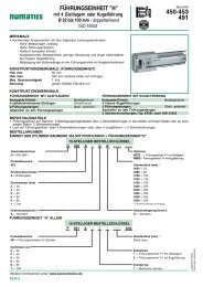
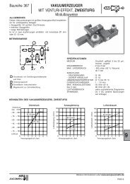
b : pressure ratio below which the fl ow is sonic:<br />
q m<br />
q* m<br />
b =<br />
Pout Pin depending on P in , T 1<br />
and C<br />
P : outlet pressure (bar)<br />
out<br />
P : inlet pressure (bar)<br />
in<br />
0 b 1<br />
Sonic fl ow Subsonic fl ow<br />
CALCULATION OF FLOW (for air and gas)<br />
. Defi ning fl ow at 6 bar :<br />
The corresponding leafl ets give for each product its mean fl ow in litres per minute at 6 bar at a standard reference atmosphere (ANR) conforming<br />
to ISO 8778 (with Δ P = 1 bar)<br />
. Calculation of fl ow :<br />
Δ P < P inlet /2<br />
Q = 28,16 x Kv x ΔP x P in<br />
including correction for temperature and density<br />
Q = 475 x Kv x (ΔP x P in )<br />
(T a x d)<br />
Q = Flow in l/min<br />
ΔP = Differential pressure, in bar<br />
. Flow graphs : (see following page).<br />
P in and T 1 are constant<br />
Ellipse quarter, depending on P in , T 1<br />
and C and b coeffi cients<br />
P out / P in<br />
Δ P ≥ P inlet /2<br />
(Maximum allowable fl ow)<br />
Q = 14 x Kv x P out<br />
P in = Absolute inlet pressure, in bar<br />
P out = Absolute outlet pressure, in bar<br />
T1, temperature (°K) measured when the fl ow is sonic<br />
including correction for temperature and density<br />
Q = 238,33 x Kv x P x 1<br />
out<br />
(T x d) a<br />
T a = Absolute temperature, in Celsius degrees<br />
d = Density compared with air<br />
All leafl ets are available on: www.asconumatics.eu<br />
P045-1<br />
A
All leafl ets are available on: www.asconumatics.eu<br />
P045-2<br />
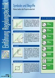
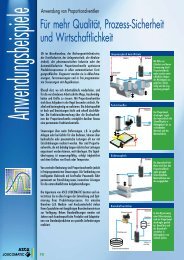
Flow graphs - <strong>ENGINEERING</strong> <strong>INFORMATION</strong><br />
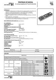
HOW TO USE THE GRAPHS<br />
Depending on the supply pressure, use the appropriate graph: either 0 - 2 bar or 0 - 40 bar.<br />
The graph shows the relationship between the fl ow and the pressure drop Δp, depending upon the upstream pressure and the fl ow<br />
coeffi cient (Kv in litres per minute).<br />
Δp3<br />
KV 132<br />
P amont : 8 bar 950<br />
Upstream P : 8 bar<br />
AIR PRESSURE 0 to 2 bar<br />
Δp<br />
Example : Find the fl ow of a valve Ø 25 mm, KV = 132, under the following conditions :<br />
– upstream gauge pressure : 8 bar<br />
– pressure drop Δp : 3 bar<br />
Proceed as shown in the diagram to fi nd a fl ow = 950 m3 /h.<br />
If the pressure drop exceeds the values shown in the graph, the fl ow is identical to that with "critical<br />
pressure drop", so that :<br />
Δp = absolute downstream pressure = absolute upstream pressure<br />
2<br />
1<br />
0,5<br />
0,1<br />
0,05<br />
0,01<br />
0,005<br />
0,001<br />
KV<br />
1<br />
1<br />
0,5<br />
5<br />
10<br />
10<br />
5<br />
50<br />
100<br />
50<br />
100<br />
500<br />
1 000<br />
5 000<br />
10 000<br />
50 000<br />
0 0,5 1<br />
P : Upstream gauge pressure in bar<br />
15 0,1 0,5 1<br />
0,1<br />
5 10<br />
1<br />
100 1 000 10 000 100 000 m3/h (ANR)✻<br />
Q :Flow<br />
10 100 1 000 10 000 I/s (ANR)✻<br />
✻ ANR : Standard reference atmosphere<br />
AIR PRESSURE 0 to 40 bar<br />
1<br />
0,5<br />
Δp<br />
0,1<br />
0,05<br />
0,01<br />
KV<br />
0 1 2 3 4 5 678910<br />
20 30 40 1 10<br />
P : Upstream gauge pressure in bar<br />
5<br />
10<br />
✻ ANR : Standard reference atmosphere<br />
500<br />
1 000<br />
5 000<br />
10 000<br />
0,1 1 10 100 1 000 10 000<br />
50 000<br />
100 000<br />
100 000<br />
100 1 000 10 000 100 000<br />
500 000<br />
100 000<br />
m3/h (ANR)✻<br />
Q :Flow<br />
I/s (ANR)✻<br />
00484GB-2006/R01<br />
Availability, design and specifi cations are subject to change without notice. All rights reserved.