Energy Conservation of Compressed-Air Supply Equipment - ECCJ
Energy Conservation of Compressed-Air Supply Equipment - ECCJ
Energy Conservation of Compressed-Air Supply Equipment - ECCJ

You also want an ePaper? Increase the reach of your titles
YUMPU automatically turns print PDFs into web optimized ePapers that Google loves.
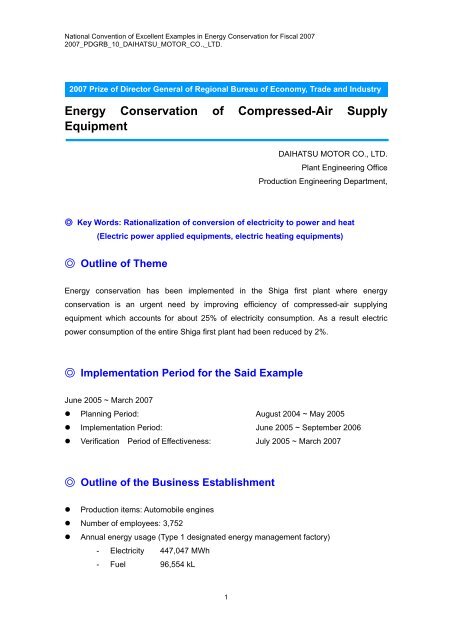
National Convention <strong>of</strong> Excellent Examples in <strong>Energy</strong> <strong>Conservation</strong> for Fiscal 2007<br />
2007_PDGRB_10_DAIHATSU_MOTOR_CO.,_LTD.<br />
2007 Prize <strong>of</strong> Director General <strong>of</strong> Regional Bureau <strong>of</strong> Economy, Trade and Industry<br />
<strong>Energy</strong> <strong>Conservation</strong> <strong>of</strong> <strong>Compressed</strong>-<strong>Air</strong> <strong>Supply</strong><br />
<strong>Equipment</strong><br />
DAIHATSU MOTOR CO., LTD.<br />
Plant Engineering Office<br />
Production Engineering Department,<br />
◎ Key Words: Rationalization <strong>of</strong> conversion <strong>of</strong> electricity to power and heat<br />
(Electric power applied equipments, electric heating equipments)<br />
◎ Outline <strong>of</strong> Theme<br />
<strong>Energy</strong> conservation has been implemented in the Shiga first plant where energy<br />
conservation is an urgent need by improving efficiency <strong>of</strong> compressed-air supplying<br />
equipment which accounts for about 25% <strong>of</strong> electricity consumption. As a result electric<br />
power consumption <strong>of</strong> the entire Shiga first plant had been reduced by 2%.<br />
◎ Implementation Period for the Said Example<br />
June 2005 ~ March 2007<br />
� Planning Period: August 2004 ~ May 2005<br />
� Implementation Period: June 2005 ~ September 2006<br />
� Verification Period <strong>of</strong> Effectiveness: July 2005 ~ March 2007<br />
◎ Outline <strong>of</strong> the Business Establishment<br />
� Production items: Automobile engines<br />
� Number <strong>of</strong> employees: 3,752<br />
� Annual energy usage (Type 1 designated energy management factory)<br />
- Electricity 447,047 MWh<br />
- Fuel 96,554 kL<br />
1
National Convention <strong>of</strong> Excellent Examples in <strong>Energy</strong> <strong>Conservation</strong> for Fiscal 2007<br />
2007_PDGRB_10_DAIHATSU_MOTOR_CO.,_LTD.<br />
◎ Overview <strong>of</strong> Target Facilities<br />
Main compressor<br />
Turbo compressor<br />
Receiver tank<br />
Header<br />
Third casting<br />
machine<br />
Second<br />
casting<br />
machine<br />
First casting<br />
machine<br />
Fourth<br />
machine<br />
Third<br />
machine<br />
Main pipe<br />
First machine<br />
Second<br />
machine<br />
Screw compressor Screw compressor Screw compressor Screw compressor<br />
1. Reasons for Theme Selection<br />
Fifth machine<br />
Fig. 1 <strong>Compressed</strong>-air supply equipment<br />
Compressor equipment<br />
capacity<br />
Turbo 900kW x 2<br />
1,200kW x 4<br />
1,500kW x 4<br />
Screw 200kW x 1<br />
600kW x 3<br />
Reciprocating 300kW x<br />
2<br />
Total 15,200kW<br />
A focus was placed on energy consumption <strong>of</strong> the compressed-air equipment<br />
Reason:<br />
In the Shiga first plant which produces automobile engines, electric consumption <strong>of</strong> the<br />
compressed-air equipment accounts for 25% <strong>of</strong> the entire electric consumption. Therefore,<br />
energy conservation by improving its efficiency was planned.<br />
2. Understanding and Analysis <strong>of</strong> Current Situation<br />
(1) Understanding <strong>of</strong> Current Situation<br />
Electricity accounts for about 60% <strong>of</strong> primary energy used in the Shiga first plant (see Fig. 2).<br />
Moreover, the compressed-air equipment accounts for about 25% <strong>of</strong> electric consumption<br />
(see Fig.3).<br />
2
National Convention <strong>of</strong> Excellent Examples in <strong>Energy</strong> <strong>Conservation</strong> for Fiscal 2007<br />
2007_PDGRB_10_DAIHATSU_MOTOR_CO.,_LTD.<br />
Coke<br />
City gas<br />
Heavy oil 3%<br />
Electricity<br />
Fig. 2 Ratio <strong>of</strong> primary energy cost<br />
(Shiga first plant)<br />
(2) Analysis <strong>of</strong> Current Situation<br />
Fourth machine<br />
equipment<br />
Fifth machine<br />
equipment<br />
<strong>Air</strong><br />
conditioning<br />
Second<br />
machine<br />
Third Casting<br />
equipment<br />
Lighting<br />
Compressor<br />
Second Casting<br />
equipment<br />
First Casting equipment<br />
Fig. 3 Ratio <strong>of</strong> electric consumption<br />
(Shiga first plant)<br />
The reason why compressors account for the higher ratio <strong>of</strong> electric consumption in the<br />
Shiga first plant is attributable to low efficiency <strong>of</strong> compressors. The factors <strong>of</strong> their low<br />
efficiency were elucidated by using a fishbone diagram shown in Figure 4. As a result, we<br />
decided to carry out improvements focusing on three points: [1] pressure loss to the plant is<br />
large, [2] equipment working under appropriate pressure has not been used, and [3] power<br />
<strong>of</strong> dehumidifiers is large.<br />
Discarded at capacity control<br />
Capacity control is performed by<br />
turbo machine<br />
There exists waste air<br />
Leaking<br />
Inefficient operation<br />
3. Progress <strong>of</strong> Activities<br />
(1) Implementation Structure<br />
Much energy loss<br />
Pipes are backed up<br />
<strong>Air</strong>-supply pipes<br />
are narrow<br />
Figure-4 Elucidate the reason by fishbone diagram<br />
Point 1<br />
Pressure loss to plant is high<br />
Distance to the edge<br />
<strong>of</strong> factory is long<br />
Point 3<br />
Power <strong>of</strong> dehumidifier is<br />
Inspiratory temperature is high<br />
Inspiratory efficiency is low<br />
Poor maintenance<br />
Unexpected failure occurs<br />
Pump power is large<br />
Poor ventilation<br />
Point 2<br />
<strong>Equipment</strong> having appropriate<br />
pressure has not been used<br />
<strong>Equipment</strong> is old and deteriorated<br />
<strong>Equipment</strong> has been used for more than 20<br />
Efficiency <strong>of</strong> auxiliary machine is low<br />
Efficiency <strong>of</strong> equipment is low<br />
There is lots <strong>of</strong> compressed air-supply equipment in the Shiga first plant whose efficiency is<br />
low. Thus, we have made efforts to improve efficiency by whole.<br />
3<br />
Efficiency <strong>of</strong><br />
compressor is low
National Convention <strong>of</strong> Excellent Examples in <strong>Energy</strong> <strong>Conservation</strong> for Fiscal 2007<br />
2007_PDGRB_10_DAIHATSU_MOTOR_CO.,_LTD.<br />
(2) Target Settings<br />
Upon promoting activities, the target was set to raise the efficiency from before improvement<br />
efficiency 8Nm3/kWh to 10Nm3/kWh.<br />
(3) Problem Points and their Investigation<br />
The following measures were decided by focusing on the three causes revealed in the<br />
analysis <strong>of</strong> current situations<br />
- Reduction in energy loss and improvement <strong>of</strong> equipment efficiency<br />
- Selection and installment <strong>of</strong> highly-efficient equipment<br />
- Development <strong>of</strong> dehumidifier system <strong>of</strong> compressed-air<br />
4. Details <strong>of</strong> Measures<br />
4-1 Reduction in energy loss and improvement <strong>of</strong> equipment efficiency<br />
(Viewpoint [1][2])<br />
(1) Current situations and points <strong>of</strong> view for improvement<br />
1) Current situations<br />
Compressors are concentrated in the center <strong>of</strong> the large Shiga first plant with floor area <strong>of</strong><br />
658,000m 2 and compressed air is supplied to the edge <strong>of</strong> plant using long piping.<br />
Accordingly, pressure <strong>of</strong> compressors is set high taking into account pressure drop caused<br />
by flow resistance in the piping.<br />
2) Points <strong>of</strong> view<br />
A focus was placed on the fact that large pressure gap is occurred between compressed-air<br />
supply side and end use side, that is to say pressure loss to the edge <strong>of</strong> factories is large.<br />
Therefore, we have taken measures to reduce such pressure loss.<br />
(2) Content <strong>of</strong> improvement<br />
Compressors were newly installed in the fifth machine plant corresponding to the vicinity <strong>of</strong><br />
the end <strong>of</strong> the current compressed-air supply piping. These compressors were used to<br />
supply compressed-air from the end <strong>of</strong> pipes to secure the set value <strong>of</strong> end pressure. This<br />
enabled reduction <strong>of</strong> supply pressure <strong>of</strong> the main compressor group.<br />
4
National Convention <strong>of</strong> Excellent Examples in <strong>Energy</strong> <strong>Conservation</strong> for Fiscal 2007<br />
2007_PDGRB_10_DAIHATSU_MOTOR_CO.,_LTD.<br />
Moreover, as lowering in the set pressure <strong>of</strong> the main compressor group became possible, it<br />
also became possible to lower the designed pressure <strong>of</strong> compressors from 0.69MPa to<br />
0.56MPa by replacing impellers <strong>of</strong> the four conventional turbo compressors (1,200kW x 4<br />
units). This resulted in improvement <strong>of</strong> equipment efficiency. (Figure-5)<br />
(3) Results<br />
Impeller before change<br />
Impeller after change<br />
Designed pressure<br />
o.69MPa<br />
Designed<br />
pressure0.59MPa<br />
Fig.5 Change to low-pressure impeller<br />
Comparison <strong>of</strong> equipment efficiency before and after the replacement <strong>of</strong> impellers <strong>of</strong> four<br />
turbo compressors (1,200kW) and lowering <strong>of</strong> designed pressure from 0.69Mpa to 0.56Mpa<br />
is shown in Table 1. Moreover, Figure 6 shows changes in characteristic curves owing to the<br />
impeller replacement. These efforts have led to a successful increase in supply air volume<br />
with the same electric consumption and improvement <strong>of</strong> equipment efficiency by 12%.<br />
Efficiency improved by 12% by lowering designed pressure from<br />
0.69MPa to 0.56MPa and changing impellers to low-pressure type<br />
Before replacement After replacement<br />
Designed pressure 0.69 (MPa) 0.56 (MPa)<br />
Supplied air volume 11,270 (Nm 3 /h) 12,810 (Nm 3 /h)<br />
Electric consumption 1,160 (kW) 1,180 (kW)<br />
Efficiency 9.7 (Nm 3 /kWh) 10.9 (Nm 3 /kWh)<br />
Table 1 Improvement <strong>of</strong> performance by replacing impellers<br />
5
National Convention <strong>of</strong> Excellent Examples in <strong>Energy</strong> <strong>Conservation</strong> for Fiscal 2007<br />
2007_PDGRB_10_DAIHATSU_MOTOR_CO.,_LTD.<br />
Before change<br />
Before replacement<br />
After change<br />
After<br />
replacement<br />
Fig. 6 Change in performance because <strong>of</strong> impeller change <strong>of</strong> turbo compressors<br />
4-2 Selection and installment <strong>of</strong> highly-efficient equipment (Viewpoint [2])<br />
(1) Current situations and viewpoints for improvement<br />
1) Current situations<br />
Most turbo compressors which are major ones in the Shiga first plant have been installed for<br />
more than 20 years. Accordingly, deterioration <strong>of</strong> equipment was found and efficiency <strong>of</strong><br />
equipment itself was low.<br />
2) Viewpoint<br />
<strong>Supply</strong> pressure was lowered by introducing highly efficient large turbo compressors and by<br />
improving the above-mentioned in 4-1. Thus, further improvement <strong>of</strong> efficiency was aimed to<br />
introduce compressors that suit supply pressure.<br />
6
Efficiency<br />
National Convention <strong>of</strong> Excellent Examples in <strong>Energy</strong> <strong>Conservation</strong> for Fiscal 2007<br />
2007_PDGRB_10_DAIHATSU_MOTOR_CO.,_LTD.<br />
(2) Content <strong>of</strong> improvement<br />
The larger the current compressors are, the higher their efficiency is. Thus, equipment<br />
efficiency was improved by introducing large turbo compressors (1,500kW) for base<br />
operation, and by changing specific pressure value from the standard setting (0.69MPa) to<br />
the special setting (0.59MPa), thereby efficiency <strong>of</strong> all compressors has improved.<br />
(3) Results<br />
<strong>Equipment</strong> efficiency has been enhanced by lowering pressure <strong>of</strong> highly efficient turbo<br />
compressors and designed pressure. Table 2 is a comparison table <strong>of</strong> performance between<br />
existing equipment and newly installed equipment. <strong>Equipment</strong> efficiency has improved by<br />
7.5% from 10.5Nm 3 /kWh to 11.3Nm 3 /kWh. Figure 7 shows change in efficiency <strong>of</strong> the entire<br />
plant.<br />
<strong>Equipment</strong> efficiency <strong>of</strong> compressors improved by 7.5% by<br />
introducing highly efficient models and lowering design pressure<br />
Existing equipment Newly installed equipment<br />
Design pressure 0.69 (MPa) 0.59 (MPa)<br />
Supplied air volume 12,800 (Nm 3 /h) 15,600 (Nm 3 /h)<br />
Electric consumption 1,223 (kW) 1,381 (kW)<br />
Efficiency 10.5 (Nm 3 /kWh) 11.3 (Nm 3 /kWh)<br />
Table 2 Comparison <strong>of</strong> performance between existing equipment and newly installed<br />
equipment<br />
Installation <strong>of</strong> 1,500kW compressors Impeller replacement<br />
Improved from 8Nm 3 /kWh to<br />
9Nm 3 /kWh<br />
Fig. 7 Change in air efficiency <strong>of</strong> each month in the Shiga first plant<br />
7<br />
After improvement<br />
Before<br />
improvement
National Convention <strong>of</strong> Excellent Examples in <strong>Energy</strong> <strong>Conservation</strong> for Fiscal 2007<br />
2007_PDGRB_10_DAIHATSU_MOTOR_CO.,_LTD.<br />
4-3 Development <strong>of</strong> dehumidifier system <strong>of</strong> compressed air (Viewpoint [3])<br />
(1) Current situations and viewpoints for improvement<br />
1) Current situations<br />
Dehumidifiers assembled into the refrigerators have been used to prevent dew<br />
condensation <strong>of</strong> moisture contained in compressed air.<br />
When dehumidification is only required not to build up condensation at the end <strong>of</strong> point<br />
where compressed air is used, excessive dehumidification causes waste.<br />
2) Viewpoint<br />
When temperature in the plant is always higher than ambient temperature, it is necessary to<br />
lower temperature to an ambient temperature to prevent dew condensation. For this<br />
purpose, use <strong>of</strong> the cooling tower method which cools air using ambient air is considered.<br />
(2) Content <strong>of</strong> improvement<br />
Use <strong>of</strong> refrigerators used as a cooling means for dehumidification was abolished. Instead,<br />
“ambient air direct-cooling dehumidifier system” using cooling towers has been developed<br />
and introduced (see Figure 8). It becomes possible to cool air down to around ambient air<br />
wet-bulb temperature by directly circulating compressed air in pipes for heat exchange<br />
inside the cooling towers and allowing ambient air passing through, at the same time<br />
spraying water.<br />
<strong>Compressed</strong> air<br />
(3) Results<br />
Thermometer<br />
Thermometer<br />
Fan<br />
Pump<br />
Tank<br />
Flow meter<br />
Ambient air direct-cooling<br />
dehumidification system Flow meter<br />
Fig. 8 <strong>Compressed</strong>-air supply system flow<br />
As shown in Figure 9, cooling effect by the ambient air direct cooling method showed<br />
sufficient performance, because air was cooled below ambient temperature. Figure 10<br />
shows the comparison <strong>of</strong> electric consumption <strong>of</strong> similar facilities (600kW compressors)<br />
8
<strong>Compressed</strong> air temperature<br />
after dehumidification (℃)<br />
National Convention <strong>of</strong> Excellent Examples in <strong>Energy</strong> <strong>Conservation</strong> for Fiscal 2007<br />
2007_PDGRB_10_DAIHATSU_MOTOR_CO.,_LTD.<br />
using refrigerators. Reduction in electric consumption by 31% was achieved for the total<br />
auxiliary machine power including dehumidifiers.<br />
Auxiliary machine power was reduced by 31% by<br />
cooling and dehumidifying ambient air using cooling<br />
tower instead <strong>of</strong> refrigerator for humidification<br />
Auxiliary machine electric energy KWh<br />
Fig. Figure 9 Cooling effect <strong>of</strong> compressed air<br />
5. Effects <strong>of</strong> Measures<br />
[1] Quantity in energy conservation: 3,485t-CO2/year<br />
[2] Amount saved: 95.855 million yen/year<br />
Ambient air direct cooling<br />
Refrigerator<br />
Fig. 10 Power reduction effect <strong>of</strong> auxiliary machine (600kW compressor)<br />
[3] Amount invested: 78.5 million yen/year (additional capital investment for the purpose <strong>of</strong><br />
energy conservation)<br />
[4] Pay back period: 0.82 year<br />
6. Summary<br />
We have started improving equipment in the order <strong>of</strong> the sizes <strong>of</strong> equipment listed as a basic<br />
procedure for promoting energy conservation in the plant.<br />
[1] Stop waste operation<br />
[2] Change set value<br />
9
National Convention <strong>of</strong> Excellent Examples in <strong>Energy</strong> <strong>Conservation</strong> for Fiscal 2007<br />
2007_PDGRB_10_DAIHATSU_MOTOR_CO.,_LTD.<br />
This includes economical modifications such as lowering the set pressure <strong>of</strong> compressed air.<br />
In recent years, improvement activities have plateaued as [1] and [2] steps have progressed.<br />
Thus, we have started capital-investment type improvement.<br />
[3] Renewal and modification to more efficient equipment<br />
This includes the modification <strong>of</strong> impellers <strong>of</strong> compressors in 4-1. This activity has already<br />
been in the third stage and there becomes few items left on which speed-up <strong>of</strong> recovery time<br />
can be performed. Capacity improvement as well as investment in accordance with renewal<br />
due to deterioration is becoming more common.<br />
[4] Change and demolition<br />
A method was changed in 4-3 to the one that does not use refrigerators <strong>of</strong> dehumidifiers.<br />
The ultimate change is to build up a production process, which does not use inefficient<br />
secondary energy, like compressed air and steam. However, focus <strong>of</strong> improvement activities<br />
will be shifted to buildup <strong>of</strong> a simple and slim production process without using energy.<br />
7. Future Plans<br />
Activities to lower the absolute value <strong>of</strong> consumption energy are performed by continuing<br />
the improvement in the manufacturing site where compressed air is consumed. At the same<br />
time, activities will continue with the aim <strong>of</strong> improving usability and production efficiency <strong>of</strong><br />
the entire air system by strengthening information exchange <strong>of</strong> equipment in the production<br />
site with the supplying side (compressors).<br />
Lowering in pressure <strong>of</strong> compressed air is only lowering energy potential <strong>of</strong> compressed air<br />
and causes increase in the consumed air quantity. We would like to double the energy<br />
conservation effects and achieve the target <strong>of</strong> 10Nm 3 /kWh not by pursuing flashy intensity<br />
and efficiency on the supplying side but by matching with the production equipments in<br />
consuming side.<br />
10