DMLS Materials - Technical Specifications
DMLS Materials - Technical Specifications
DMLS Materials - Technical Specifications

You also want an ePaper? Increase the reach of your titles
YUMPU automatically turns print PDFs into web optimized ePapers that Google loves.
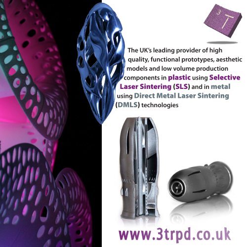
The UK’s leading provider of high<br />
quality, functional prototypes, aesthetic<br />
models and low volume production<br />
components in plastic using Selective<br />
Laser Sintering (SLS) and in metal<br />
using Direct Metal Laser Sintering<br />
(<strong>DMLS</strong>) technologies<br />
www.3trpd.co.uk
I N T R O D U C T I O N<br />
3T<br />
RPD Ltd is a market leader in<br />
Rapid Product Development<br />
providing Rapid Prototyping and<br />
Rapid Manufacturing services to a<br />
diverse range of industry sectors ...<br />
... including Aerospace, Architecture,<br />
Automotive, Dental, Medical, FMCG, Marine,<br />
Defence and Pharmaceutical. With the UK’s<br />
largest Selective Laser Sintering (SLS) facility,<br />
we are now leading the way in the supply of<br />
metal parts using Direct Metal Laser Sintering<br />
(<strong>DMLS</strong>) throughout the UK and Europe.<br />
We specialise in the cost-effective, fast<br />
and extremely accurate production of<br />
complex and functional prototypes,<br />
aesthetic models and low volume<br />
production components directly<br />
from 3D CAD data, negating the need<br />
for conventional tooling.<br />
Offering<br />
a wide range of both plastic and<br />
metal materials, together with some<br />
SLS combining<br />
functionality with<br />
quality aesthetics<br />
of the world’s largest Laser Sintering machines, we<br />
can supply parts in just a matter of days. And with<br />
Engineers, Architects and Designers using these<br />
technologies to revolutionise the speed at which<br />
products can be brought to market coupled with<br />
new opportunities for low volume production,<br />
Rapid Manufacturing is becoming a reality for many.<br />
With innovation and research at the forefront<br />
of our business, we have the right skills in place<br />
through our team of highly trained engineers and<br />
finishers to ensure that we consistently gain the<br />
best from these technologies. We are committed to<br />
quality assurance in our manufacturing processes,<br />
products and delivery and in recognition of this,<br />
we have gained both ISO 9001:2000 and ISO<br />
13485:2003 Medical Devices accreditations.<br />
Example of Rapid<br />
Manufacturing; bed of Aerospace<br />
parts in Cobalt Chrome<br />
Example of how <strong>DMLS</strong><br />
can be used in a<br />
medical application<br />
As we continue to expand into other market sectors<br />
and develop our service offering, the ISO quality<br />
framework will ensure that we offer exceptional<br />
reliability and service, and the highest quality products<br />
that our customers have come to expect from us.<br />
Dental Copings and Bridges<br />
Functional SLS prototype<br />
tested in true working<br />
environments<br />
By asking for the impossible, obtain the best possible<br />
Italian Proverb
W H A T I S S L S & F I N I S H I N G<br />
What is Selective Laser Sintering?<br />
SLS is a process of fusing together layers of<br />
powder (eg. Nylon, Glass Filled Nylon or Alumide) into<br />
a 3D model by a computer-directed heat laser. 3D<br />
CAD data of a new product or prototype component is<br />
sliced into layers, and the lasers sinter (melt) the powder<br />
layer by layer. Additional powder is deposited on top of<br />
each solidified layer and again sintered.<br />
The process is self-supporting and parts can<br />
therefore be nested together. The ‘selective’ nature<br />
of the lasers enable complex geometries to be<br />
achieved without compromising on functionality.<br />
SLS provides the highest level of functionality<br />
combined with speed that is currently available.<br />
We are uniquely able to build<br />
prototypes on both EOS<br />
and 3D Systems machines,<br />
boasting some of the world’s<br />
largest SLS machines - four<br />
EOS P700/730s, two EOS P380’s and a 3D Systems HiQ<br />
2500 Plus - thus enabling us to provide the optimal<br />
machine to meet our customers’ requirements. Large<br />
parts are built in single pieces up to a build volume<br />
of 700x380x580mm on the P700/730’s; the reduced<br />
need for joints and post-assembly dramatically<br />
increasing their functionality.<br />
www.3trpd.co.uk<br />
The P380’s allow<br />
parts to be built up to 620x340x340mm, and smaller<br />
parts with finer detail can be produced on the DTM.<br />
What are the finishing options?<br />
The layer based construction techniques<br />
of SLS offer significant benefits in terms of build<br />
speed, however it can sometimes give a<br />
stepped surface finish.<br />
From a purely functional<br />
aspect this is seldom a problem, however<br />
from the aesthetic perspective they may require<br />
additional finishing.<br />
Our skilled team of<br />
finishers combine the<br />
functionality of SLS<br />
parts with high quality<br />
aesthetics, with minimal time added to the delivery.<br />
Providing a range of finishing techniques from simply<br />
adding a colour or highlighting certain areas, to fully<br />
finished marketing models, a finished prototype can<br />
play a vital role in functionality testing, securing tender<br />
bids, design verification and marketing photography.<br />
Furthermore, we have pioneered a low cost method<br />
of improving the visual impact of our prototype<br />
components with a revolutionary colouring<br />
process.<br />
Single parts or large batches can be<br />
supplied in a range of standard colours. Requiring<br />
no surface dressing, this post-process is usually<br />
covered by a flat charge irrespective of parts count.<br />
Assemblies become<br />
clearer and resilience to<br />
handling discolouration is enhanced, giving a far<br />
better communication of design intent.
F U N C T I O N A L I T Y<br />
How functional are SLS prototypes?<br />
A simple test was carried out by<br />
parking an Audi A4 car on one of our SLS<br />
prototypes! The housing, 40mm high with a 6mm<br />
wall section, was to be cast in Steel in production. The<br />
result was no damage to the part (apart from some<br />
tyre discolouration!).<br />
In order to demonstrate functionality<br />
still further, we purchased a Smart Car<br />
with the intention of replicating or redesigning<br />
components, re-building them in SLS and<br />
testing them in everyday conditions. Together with<br />
Crucible Industrial Design Ltd, the complete front<br />
end of the Smart car was re-designed and built in SLS,<br />
fitted to the car and driven in every road and weather<br />
condition imaginable for over 2,000 miles, with no<br />
detrimental effect to the SLS components.<br />
The project began conventionally,<br />
with designers from Crucible<br />
submitting rendered sketches of a<br />
re-designed front end. Due to the<br />
reverse engineering aspect of the project, 3D Scanners<br />
digitised the front of the car to provide a digital surface<br />
that could be read into SolidWorks. Once a final design<br />
was decided upon, Crucible created a 3D CAD model<br />
which was then supplied to us for SLS components to<br />
be built.<br />
The ability of the Smart car’s body panels to be<br />
completely removed and replaced within four hours<br />
allowed access to the chassis fixtures and fittings,<br />
which gave fixed anchor points for the final design.<br />
Critical components such as the door pillars and<br />
bumper fixtures had to be considered, and the<br />
windscreen washer and brake fluid reservoirs had to<br />
remain accessible to ensure the car’s performance<br />
wasn’t compromised.<br />
The car was driven at speeds of up to 70mph, in wet,<br />
muddy conditions as well as hot, dry weather, and<br />
parked outside in sub-zero temperatures. It was taken<br />
on some journeys of almost 3 hours without stopping.<br />
The success of this project has proved, beyond<br />
doubt, the capability, functionality and durability<br />
of our SLS prototypes.<br />
A closed mind is like a closed book; just a block of wood<br />
Chinese Proverb
C A S E S T U D Y<br />
Record RSS is a market leader<br />
in the provision of innovative and<br />
reliable play solutions providing safe play<br />
equipment for children of all ages who now<br />
demand more fun, increased challenges<br />
and stimulating equipment to mirror their<br />
influences and aspirations.<br />
Their designers were challenged to come up with<br />
a dynamic, exhilarating ride for children aged 7<br />
through to adulthood and from initial ideas came<br />
the RidgeRider; an elliptical track with a moving<br />
seat, likened to a mini roller coaster. The inner<br />
workings of the seat and how it could be safely<br />
mounted onto the track took months to finalise,<br />
but then they needed a method of creating a costeffective,<br />
working prototype of it for testing on the<br />
track itself.<br />
They turned to us as our Selective Laser Sintering<br />
(SLS) technology was the ideal solution and the<br />
best way of building the seat in a material that was<br />
durable enough to withstand functional testing,<br />
within a short leadtime. Special features were<br />
incorporated into the complex internal workings<br />
of the seat to ensure the safety of fingers and hands<br />
of both riders and spectators.<br />
www.3trpd.co.uk<br />
Made in two mirrored parts, it simply clipped<br />
together, thereby creating a protective housing over<br />
the track as well as a functional seat for the rider.<br />
The Nylon material used to produce the prototype<br />
model emulated the final production material; rotomoulded<br />
polyethylene; so much so in fact, that<br />
our <strong>Technical</strong> Sales Engineer actually rode it when<br />
it was being demonstrated at an exhibition! This<br />
functionality enabled the designers to prove their<br />
design prior to going into<br />
final production, without<br />
the need for expensive<br />
tooling.<br />
The RidgeRider being<br />
demonstrated at Saltex 2007<br />
“Andrew Kadis, Design Manager at Record RSS said,<br />
“The quick turn around from sending 3T our CAD data to<br />
receiving the SLS prototypes enabled us to demonstrate the<br />
product to the British Standards Institution for testing, as<br />
well as allowing us to show the product at our major annual<br />
exhibition, Saltex 2007, where it made a huge impact.”
C A S E S T U D Y<br />
Architect Zaha Hadid<br />
consistently pushes the<br />
boundaries of architecture and urban<br />
design. We produced scale models of<br />
the Guggenheim Museum in Taichung,<br />
Taiwan, which were delivered as an<br />
architectural presentation to the office<br />
of the Mayor of Taichung, to promote<br />
the project.<br />
Due to the complex organic forms of Zaha’s design<br />
and the need to show an accurately presented<br />
final design, SLS was deemed the best solution for<br />
achieving and meeting their requirements.<br />
To place the model in context, the laser sintered<br />
‘building’ was merged with a CNC ‘landscape’ to<br />
underline the synergy of the proposal.<br />
Over 2m long, the resulting 3D model gave an<br />
incredible visual image of the proposed building<br />
when compared alongside the computer generated<br />
artist’s impression, allowing the Mayor’s office to see,<br />
touch and feel an actual tactile scale version of the<br />
proposal.<br />
“Dillon Lin, Project Architect for<br />
Zaha Hadid says “The SLS piece gave<br />
a very convincing presentation model<br />
that the mayor of Taichung is putting<br />
to good use in promoting the project.<br />
When accuracy is required with complex forms, SLS proves<br />
to be an economic process for producing models of these<br />
forms when compared to other, more expensive options,<br />
including making them by hand, which is extremely labour<br />
intensive.”<br />
”<br />
By learning you will teach; by teaching<br />
you will learn<br />
Latin Proverb
C A S E S T U D Y<br />
Urban Bicycle is a polymer bicycle<br />
designed to meet the needs of the<br />
inner-city commuter and town cyclist.<br />
We produced functional and aesthetically pleasing<br />
prototypes to assist Paul Wolfson in his final year<br />
of study in Industrial Design and Technology at<br />
Loughborough University.<br />
Paul’s intention was<br />
to challenge traditional bicycle manufacturing<br />
techniques and prove that polymeric materials would<br />
be suitable to produce a viable product.<br />
The simplistic design was effectively replicated using<br />
the SLS prototyping technology, with the parts being<br />
produced directly from CAD data used extensively<br />
during the design process for both development and<br />
presentation of the concept, saving a considerable<br />
amount of time in creating a final prototype.<br />
The SLS prototype had the necessary physical<br />
properties to fully test the concept, and was suitable<br />
to undergo further modelmaking work in order to<br />
make it appear as the desired design would.<br />
“Paul Wolfson, Designer of the<br />
Urban Bike says “The functionality of 3T’s SLS<br />
prototypes far exceeded my expectations, as I<br />
never envisaged that I would actually be able to<br />
assemble the bicycle and ride it! Prototyped at the<br />
intended wall thickness of the production part<br />
gave me a realistic representation of my design,<br />
without any modifications having to be made.”<br />
www.3trpd.co.uk<br />
”
Stewart Golf design,<br />
develop and manufacture<br />
luxury powered golf caddies and<br />
recently launched the F1 Lithium to the<br />
market; a fully remote-controlled top of<br />
the range golf trolley, retailing at £2,500.<br />
SLS model before and after finishing<br />
C A S E S T U D Y<br />
It was imperative that the new design was tried and<br />
tested before going ahead with full production and,<br />
using our Rapid Prototyping services, they were able<br />
to generate 3-dimensional models direct from 3D CAD<br />
data using Selective Laser Sintering (SLS) technology.<br />
The resulting tactile models enabled the designers<br />
to make small design modifications along the way,<br />
without the need to invest in unnecessary tooling<br />
which could prove expensive and time-consuming.<br />
During previous product development, the designers<br />
at Stewart Golf have used both Stereolithography (SLA)<br />
as well as SLS. However, they found that whilst SLA<br />
can be produced to a high quality finish, the material<br />
Furthermore, the self-supporting nature of the SLS<br />
process enables large hollow parts to be produced.<br />
With some clever positioning of through-holes by the<br />
designers, our modelmakers were able to remove the<br />
unsintered powder from inside the cavity walls. The<br />
holes were then carefully sealed to allow a smooth<br />
finish to be achieved. The SLS Nylon material emulated<br />
that of the actual production material, thereby allowing<br />
the designers to create a realistic weight for the parts,<br />
making their testing all the more accurate. Had the<br />
parts been produced in several pieces and later joined<br />
together, this could have compromised both the<br />
strength and functionality.<br />
itself was too weak for functional testing and became “Jon Miller, Engineering Director at Stewart Golf says “As<br />
good as 3D CAD systems are, there is nothing better than having a realistic<br />
affected by atmospheric conditions, making them and fully functional product in your hands. The SLS models enabled the<br />
either brittle or too flexible. However, it is possible to Stewart Golf team to discuss every feature of the product in great detail,<br />
ranging from the overall appearance and styling of the product to the<br />
achieve an extremely high standard of finishing with smallest of tooling details. The complete SLS prototype was also used for<br />
SLS. Ours team of skilled modelmakers and finishers demonstration purposes at our distributors, enabling them to appreciate<br />
the concept and performance improvements. Furthermore, the individual<br />
can create high quality aesthetics, generating a model components along with 3D CAD data were taken to our suppliers to ensure<br />
that is comparable to the final manufactured item. the parts could be easily manufactured without the need for expensive<br />
tooling modifications.”<br />
”<br />
The resulting prototype model of the F1 Lithium Golf<br />
Trolley not only enabled Stewart Golf to produce<br />
photography for pre-product launch literature, but<br />
A bargain is something you don’t need<br />
at a price you can’t resist<br />
the models were also robust enough to allow final<br />
English Proverb<br />
product testing both on and off the golf course.
C A S E S T U D Y<br />
Nottingham<br />
University<br />
Hospital Trust, Loughborough<br />
University and Delcam Ltd have collaborated<br />
on the ‘Facemaker’ project, taking advantage<br />
of our 3-dimensional modelling techniques<br />
to offer alternative methods to patients who<br />
require a facial prosthesis.<br />
By removing the need for direct contact in making the<br />
prosthetics and rehabilitation aids, digital methods<br />
offer substantial benefits to patients following cancer,<br />
facial trauma or a congenital abnormality of the face.<br />
Traditionally, a direct mould of the face would have<br />
been taken which is heavy, easily distorted, time<br />
consuming and potentially extremely painful to<br />
the patient.<br />
Maxillofacial Prosthetists would then<br />
generate a replica of the patients’ missing skin and<br />
bone using craft based skills; sculpting, constructing<br />
and moulding the prosthesis to match as close as<br />
possible the missing part. These techniques have not<br />
changed significantly for 30 years.<br />
The ‘Facemaker’ project makes use of the ‘Cobra Fast<br />
Scan’ from Polhemus, USA, collecting data directly<br />
from the patient in a non-contact manner.<br />
www.3trpd.co.uk<br />
This<br />
enables the Maxillofacial Prosthetists to reproduce<br />
the missing part using Delcam’s CopyCAD software<br />
(Figure 1). They then mirror image the remaining parts<br />
to generate a prosthesis template for the defect site,<br />
which is then manufactured using our Selective Laser<br />
Sintering (SLS) technology (Figure 2). The mirrored<br />
part creates a template for the final sculpting of a new<br />
prosthesis which is then adapted to accurately fit the<br />
patient (Figure 3).<br />
Fig. 1<br />
Fig. 3<br />
Furthermore, this innovative project can help patients<br />
who have suffered facial burns and require pressure<br />
therapy splints or head radiotherapy immobilisation<br />
splints, and also assist in surgical planning for cleft<br />
lip and palate babies, where it is extremely difficult<br />
to obtain 3D images of the affected areas unless<br />
the baby is put to sleep.<br />
As more challenging and<br />
complex procedures are being carried out, the ability<br />
to inexpensively and efficiently produce customised<br />
devices and models using Rapid Prototyping<br />
techniques is becoming increasingly<br />
attractive for many specialist areas<br />
within the medical sector.<br />
Fig. 2<br />
Figure 1<br />
Ear scan data manipulated in CopyCAD<br />
Figure 2<br />
Mirror image of the remaining right ear<br />
rapid manufactured (3T) to produce a<br />
prosthesis template for the defect side<br />
Figure 3<br />
Final ear prosthesis in position
C A S E S T U D Y<br />
Marks Barfield Architects<br />
believe that good design<br />
transforms the quality of the<br />
environment and aim to provide an<br />
architecture that is innovative,<br />
sustainable, an imaginative response to<br />
context and a pleasure to experience.<br />
One such example of this is the Xstrata Treetop<br />
Walkway in Kew Gardens, due to open in Spring<br />
2008 as part of the ‘Year of the Tree’ celebrations.<br />
This will be a thrilling experience, taking visitors 18m<br />
high into the tree canopies along a 200m long loop<br />
for a birds-eye view of Kew. It will provide insights<br />
into the special role of trees in our breathing planet<br />
and intimate views of deciduous woodland and its<br />
inhabitants from within the tranquility of the leaves.<br />
Marks Barfield used their in-house 3D CAD software<br />
to design the treetop attraction and commissioned<br />
us to build scale models of some of the key elements<br />
of the structure to illustrate the concept, namely the<br />
main stair tower and a section of the walkway.<br />
As the UK’s leading specialist in Rapid Prototyping, we<br />
used our Selective Laser Sintering (SLS) technology<br />
to translate the CAD data into tactile, 3-dimensional<br />
models. SLS lends itself perfectly to creating complex<br />
shapes and surfaces, and is a much quicker, more<br />
accurate and cost-effective process when compared<br />
to other more traditional model-making techniques.<br />
Produced in Nylon, the models gave an extremely<br />
accurate representation of Marks Barfield’s design,<br />
with the complex arrangement of the walkway truss<br />
bracing elements being precisely replicated.<br />
Our team of skilled finishers and modelmakers used<br />
a fine mesh material to replicate the sides and floor<br />
of the walkways, painstakingly attaching it by hand,<br />
before sending the models to Andrew Ingham &<br />
Associates, who added trees and people to give a true<br />
representation of the design.<br />
SLS Model of<br />
main Stair Tower<br />
A picture paints a thousand words<br />
American Proverb
C A S E S T U D Y<br />
Finished model giving a true representation of the design<br />
Photographs of the actual structure in Kew Gardens, opened Spring 2008<br />
“Chris Smiles says “Workflow between us and 3T was extremely efficient, with no<br />
information being lost in translation between our design data and the generation of<br />
the models. For a structure this complex, having an actual 3D model enabled us to<br />
evaluate the proposal more effectively than simply relying upon a 2- or 3-dimensional<br />
virtual image. The model itself has been a valuable tool for Kew in promoting the<br />
project to potential sponsors and stakeholders”<br />
www.3trpd.co.uk/architecture
C A S E S T U D Y<br />
PSM Instrumentation<br />
is a UK designer<br />
and manufacturer of specialised process<br />
measurement/control instrumentation for the Marine,<br />
Chemical, Water and Food & Beverage industries.<br />
Their unique Water Level Alarm/Indicator provides a<br />
simple, robust and reliable solution where an immediate<br />
visual warning is needed of the possible hazards of<br />
flooding, eg. in underground high voltage sub-stations.<br />
Their requirement was for 8,000 units, and whilst<br />
we are specialists in the fast, accurate production<br />
of one-off prototype components, we also offer the<br />
economical manufacture of small series parts as<br />
final products; namely Rapid Manufacturing; a<br />
fast, flexible and cost-effective method of generating<br />
otherwise ‘impossible to build’ end-use parts directly<br />
from CAD data, with no tooling required.<br />
PSM’s design consisted of a multi-component unit of<br />
The design required a lightweight production<br />
material to aid the buoyancy of the product. The<br />
Nylon used in the SLS process proved ideal, and the<br />
ease with which the parts could be assembled enabled<br />
the unit to be sealed and made waterproof without<br />
any additional post-processing work.<br />
60mm<br />
When the float rises with incoming floodwater, the<br />
internal spring mechanism ‘latches’ at the highest<br />
recorded level. The flexibility and ‘spring-like’ action<br />
of the SLS material enables the latching function to<br />
work extremely efficiently.<br />
four parts and the physical attributes required by the<br />
“Sean Lane, <strong>Technical</strong> Support at<br />
main housing took full advantage of the SLS process, PSM Instrumentation Ltd says “SLS<br />
as it enables part design to be unconstrained and<br />
was the preferred method of manufacture<br />
as due to the shape of the components it<br />
functionality-led. The float housing could be built in would have been too expensive to have<br />
one piece as the ‘selective’ nature of the SLS process them machined from anything solid<br />
or cast, and the leadtimes would have<br />
enables complex geometries to be achieved, such been much longer than offered by 3T’s<br />
”<br />
as holes and cavities, with the ‘unsintered’ or loose technology.”<br />
material simply being removed and recycled for future<br />
use. The internal workings incorporated undercuts,<br />
levers and living springs essential to its mechanical<br />
function.<br />
Furthermore, the float<br />
needed to be of high visibility, so our revolutionary<br />
colouring process was used to colour the parts a<br />
bright orange and yellow.<br />
< Float<br />
assembly<br />
with reset<br />
levers (cut)<br />
Assembled<br />
float ><br />
Advice is least heeded when most needed<br />
English Proverb
C A S E S T U D Y<br />
Ian<br />
Helmore, a water treatment<br />
specialist, used our SLS services to<br />
produce prototype components for his latest<br />
invention; Steri-Spray®, which appeared on<br />
Dragon’s Den; BBC TWO’s business venture<br />
capitalist programme.<br />
During routine water testing at a hospital Ian detected<br />
a positive Legionella sample on one of the showers.<br />
The hospital had to take all 50 of their showers<br />
out of service for two weeks and Ian felt this was<br />
unacceptable. As a result he invented the Steri-Spray®<br />
range of showers.<br />
During its development, Ian needed to prototype<br />
his design in order to assemble and test it, as well<br />
as presenting an aesthetic model of it to potential<br />
investors. He therefore used our Rapid Prototyping<br />
expertise to obtain prototypes using Selective Laser<br />
Sintering (SLS) technology. Over 20 individual<br />
components that make up the shower system<br />
were produced in Nylon, including inserts, tubes,<br />
back plates, covers, connectors and the shower rose<br />
itself. Our specialist team then expertly finished and<br />
painted the parts, making them look like the final<br />
manufactured product.<br />
Ian was able to demonstrate the concept to the<br />
Dragons; a panel of 5 successful multi-millionaire<br />
business people. His pitch was for a £145,000<br />
investment for a 10% stake in his potentially lifesaving<br />
invention. Theo Paphitis was willing to split<br />
the deal with Deborah Meaden, and Ian secured the<br />
www.3trpd.co.uk<br />
full £145,000 investment for 40%<br />
of his business shared between the<br />
two Dragons.<br />
This investment meant that Steri-<br />
Spray® could move toward production<br />
within a very short period of time.<br />
More importantly, Deborah and<br />
Theo’s invaluable business experience<br />
will assist Ian in making Steri-Spray®<br />
become a worldwide commercial<br />
brand name.<br />
“Ian Helmore says “The laser sintering process at 3T was new to<br />
me and just what was required to prove that our expensive tooling<br />
for Steri-Spray was going to be correct prior to ordering it. I was<br />
given a first rate, personal service from the moment I sent the files,<br />
to when I received the final finished products. The finishing process<br />
was absolutely superb and done with such attention to detail<br />
”<br />
that people think they are the actual manufactured products.”
Largest SLS Bureau in the UK - 3T’s SLS Machines<br />
EOS P730 EOS P380 3D Systems HiQ<br />
Quantity: 4 off 2 off 1 off<br />
Laser Type: CO 2 (twin) CO 2 CO 2<br />
Laser Spot Diameter: 0.75mm 0.75mm 0.45mm<br />
S L S P L A N T L I S T<br />
Layer Thickness:<br />
Build Chamber/<br />
Part Size:<br />
<strong>Materials</strong>:<br />
Our SLS facility<br />
0.15mm<br />
700 x 380 x 580mm<br />
(single piece)<br />
• Nylon (Polyamide<br />
PA2200)<br />
• Glass Filled Nylon<br />
(Polyamide PA3200)<br />
0.15 to 0.2 mm<br />
depending on material<br />
340 x 340 x 620mm<br />
(single piece)<br />
• Alumide<br />
• Nylon (Polyamide<br />
PA2200)<br />
• Glass Filled Nylon<br />
(Polyamide PA3200)<br />
• PrimeCast 101<br />
(Polystyrene)<br />
0.1mm upwards<br />
depending on material<br />
330 x 280 x 457mm<br />
(single piece)<br />
• Nylon (Polyamide<br />
PA2200)<br />
• Glass Filled Nylon<br />
(Polyamide PA3200)<br />
Keep quiet and people will think you a philosopher<br />
Latin Proverb
S L S M A T E R I A L S<br />
Nylon 12 (Polyamide PA2200)<br />
By far the most common material used in SLS, parts have good long term stability, offering resistance to most<br />
chemicals. It is harmless to the environment and safe to use with foodstuff. Complexity is irrelevant and<br />
the material delivers the impact strength and durability required for functional testing. Tensile and flexural<br />
strength combine to make tough prototypes, with the flex associated with many production thermoplastics.<br />
It is able to emulate living hinge designs, certainly to 20+ cycles. The material is non-hygroscopic, thereby<br />
negating the requirement to seal the surface on components being used with liquids.<br />
Glass Filled Nylon 12 (Polyamide PA3200)<br />
This is the Glass Filled variant of PA2200. Providing greater rigidity, the glass-filled blend is perfect when<br />
prototyping rigid parts intended for production in advanced engineered thermoplastics, and is the right<br />
choice for functional testing. Form, fit and functional testing can now be completed without sacrifice.<br />
The filler is glass bead and not fibre, hence the part predominantly increases in stiffness but not strength.<br />
Filler ratios approximately 40%. The material is non-hygroscopic, thereby negating the requirement to<br />
seal the surface on components being used with liquids.<br />
Polystyrene (PrimeCast 101)<br />
This is a Polystyrene material originally conceived as a sacrificial master for investment casting purposes. In<br />
lieu of making a tool the CAD design would be manufactured directly in this material and the component<br />
then treated sacrificially as per wax in investment casting. For complex or short lead-time items, this<br />
can offer significant speed and cost savings. Subsequent work has highlighted how well this material<br />
functions as a master pattern for Vacuum Casting as an alternative to Stereolithography.<br />
Alumide<br />
The manufacture of stiff parts of metallic appearance for applications in automotive (eg. wind tunnel<br />
tests or parts that are not safety-relevant), tool inserts for injecting and moulding small production runs,<br />
illustrative models (metallic appearance), education and jig manufacture, among other aspects. Surfaces<br />
of parts can be finished by grinding, polishing or coating. An additional advantage is that low tool-wear<br />
machining is possible eg. milling, drilling or turning.<br />
www.3trpd.co.uk<br />
Selective Laser Sintering <strong>Materials</strong>
ALUMIDE NYLON GLASS FILLED NYLON POLYSTYRENE<br />
S L S M A T E R I A L S<br />
MATERIAL PROPERTIES VALUE UNITS VALUE UNITS VALUE UNITS VALUE UNITS<br />
Density of lasersintered<br />
part<br />
1.36 ±<br />
0.05<br />
g/cm³ 0.9 - 0.95 g/cm³<br />
1.23<br />
- 1.28<br />
g/cm³<br />
0.70<br />
- 0.85<br />
g/cm³<br />
MECHANICAL PROPERTIES VALUE UNITS VALUE UNITS VALUE UNITS VALUE UNITS<br />
Tensile modulus<br />
Tensile Strength,<br />
X-/Y-direction<br />
Tensile Strength,<br />
Z-direction<br />
3800 ±<br />
150<br />
N/mm²<br />
1700 ±<br />
150<br />
46 ± 3 N/mm² 45 ± 3<br />
N/mm² or<br />
MPa<br />
N/mm² or<br />
MPa<br />
3200 ±<br />
200<br />
48 ± 3<br />
N/mm² or<br />
MPa<br />
N/mm² or<br />
MPa<br />
1600 ±<br />
250<br />
N/mm²<br />
5.5 ± 1.0 N/mm²<br />
1.2 ± 0.3 N/mm²<br />
Elongation at break 3.5 ± 1 % 20 ± 5 % 6 ± 3 % 0.4 ± 0.1 %<br />
Flexural modulus<br />
Charpy – Impact<br />
strength<br />
Charpy – Notched<br />
impact strength<br />
Izod – Impact<br />
strength<br />
Izod – Notched<br />
impact strength<br />
Ball Indentation<br />
Hardness<br />
3000 ±<br />
150<br />
N/mm²<br />
1240 ±<br />
130<br />
N/mm² or<br />
MPa<br />
2100 ±<br />
150<br />
N/mm² or<br />
MPa<br />
29 ± 2 kJ/m² 53 ± 3.8 kJ/m² 35 ± 6 kJ/m²<br />
4.6 ± 0.3 kJ/m² 4.8 ± 0.3 kJ/m² 5.4 ± 0.6 kJ/m²<br />
32.8 ± 3.4 kJ/m² 21.3 ± 1.7 kJ/m²<br />
4.4 ± 0.4 kJ/m² 4.2 ± 0.3 kJ/m²<br />
77.6 ± 2 98<br />
Shore D hardness 76 ± 2 80 ± 2<br />
THERMAL PROPERTIES VALUE UNITS VALUE UNITS VALUE UNITS VALUE UNITS<br />
Melting Point 172 - 180 °C 172 - 180 °C 172 - 180 °C<br />
Vicat softening<br />
temperature B/50<br />
Vicat softening<br />
temperature A/50<br />
Heat conductivity 0.5 - 0.8 W(mK) -1<br />
Glass Transition<br />
Temperature<br />
Material<br />
Destruction<br />
Remaining Ash<br />
Content<br />
169 °C 163 °C 166 °C<br />
181 °C 179 °C<br />
150 ± 1 °C<br />
250 - 550 °C<br />
0.002 %<br />
Be prepared<br />
Boy Scout Motto
W H A T I S D M L S ?<br />
What is Direct Metal Laser Sintering?<br />
Direct Metal Laser Sintering (<strong>DMLS</strong>) is a<br />
revolutionary technology that produces otherwise<br />
‘impossible-to-make’ end-use metal parts<br />
directly from your 3D CAD data, whilst negating<br />
the investment in time and money of conventional<br />
tooling.<br />
The parts produced are comparable to<br />
a good investment cast part and the mechanical<br />
properties are comparable to those of a cast or<br />
machined component.<br />
The <strong>DMLS</strong> process is not restrictive in its application<br />
and the components produced can be used in place<br />
of almost any conventionally manufactured part,<br />
whether they would normally<br />
be machined or cast.<br />
The<br />
advantage of the process is<br />
that the more complex or<br />
feature rich the component,<br />
the more economical the<br />
process becomes.<br />
<strong>DMLS</strong> is an ‘additive’<br />
technology that works by<br />
fusing together very fine<br />
layers of metal powder using<br />
a focussed laser beam.<br />
www.3trpd.co.uk/dmls<br />
A<br />
support structure is required<br />
CAD Model<br />
Sintered Part<br />
to hold the parts in position during building and this<br />
is anchored onto a steel platform. The supports and<br />
components are built with a layer thickness ranging<br />
from 20 to 60 microns depending on the material<br />
used. Each layer is scanned with the laser fusing the<br />
powder to layer below and forming the new build<br />
layer, the base is lowered one layer, a fresh layer of<br />
powder is deposited, and the next layer is scanned. A<br />
powerful 200W Yb-fibre laser is precisely controlled<br />
in the X and Y co-ordinates allowing for exceptional<br />
tolerances to be held (
F I N I S H I N G O P T I O N S<br />
What are the finishing options?<br />
Metal parts can be supplied ‘asbuilt’<br />
or finished using various post processing and<br />
finishing techniques by our team of expert finishers.<br />
Dependant upon the material used, there are various<br />
forms of finishing available:-<br />
Shot-peening is a cold working process used to<br />
produce a compressive residual stress layer and modify<br />
mechanical properties of metals. It entails impacting a<br />
surface with shot (round metallic or ceramic particles)<br />
with force sufficient to create small indentations or<br />
dimples.<br />
It is similar to sandblasting, except that it<br />
operates by the mechanism of plasticity rather than<br />
abrasion: each piece of shot striking the material acts<br />
as a tiny peening hammer. In practice, this means that<br />
less material is removed by the process, and less dust<br />
created. Shot peening may be used for cosmetic effect.<br />
The surface roughness resulting from the overlapping<br />
dimples causes light to scatter upon reflection.<br />
Because peening typically produces larger surface<br />
features than sand-blasting, the resulting effect is<br />
more pronounced.<br />
Part in Cobalt Chrome<br />
shot-peened with Metal<br />
Part in Cobalt Chrome shotpeened<br />
with Metal & Ceramics<br />
Metal Polishing is the process of smoothing metals<br />
and alloys and polishing to a bright, smooth, mirrorlike<br />
finish. This can enhance the aesthetic appearance<br />
of parts as well as preventing corrosion, particularly<br />
those being used in automotive and aerospace<br />
environments. Medical instruments can also be highly<br />
polished to maintain hygienic conditions and prevent<br />
contamination in marks in the metals.<br />
Polishing is a metal-finishing operation where articles<br />
are polished using abrasives or mops, in a multistage<br />
process. Firstly, coarse grit abrasives are applied at<br />
high speed to remove surface defects like pits, nicks,<br />
lines and scratches. Then fine grit abrasives are used<br />
to remove the residue and smooth the surface. Finally,<br />
cotton mops are used to give a mirror-like finish to<br />
the articles. Lubricants such as wax, diesel fuel and<br />
kerosene are used as lubricating and cooling media<br />
during these operations. Sophisticated computercontrolled<br />
machines can be used to polish intricately<br />
shaped articles, although much of this work can also<br />
be carried out by hand.<br />
Examples of finished <strong>DMLS</strong> parts, highly polished<br />
Ask the experienced rather than the learned<br />
Arabic Proverb
D M L S A P P L I C A T I O N S<br />
Applications for <strong>DMLS</strong><br />
<strong>DMLS</strong> is fast becoming a recognised<br />
manufacturing method for the fast, accurate<br />
production of one-off prototype components or for<br />
the economical manufacture of small series parts for<br />
testing purposes, or as final products for use in many<br />
different environments.<br />
The process generates hard wearing but intricate<br />
components, opening up opportunities to all<br />
industries, including Aerospace, Automotive,<br />
Electronic and Medical, and for generating Tooling<br />
Inserts. Certain materials give the parts rigidity and<br />
weight, thereby making it attractive to the aerospace<br />
and automotive sectors for vigorous testing and use<br />
in a wind tunnel. The strength of the process makes it<br />
attractive to the medical sector, and the high levels of<br />
finishing produces parts that are sterile and hygienic.<br />
More and more industries are using physical models<br />
throughout their product development cycle,<br />
dramatically reducing their time to market and<br />
assisting them with:-<br />
• Communication of ideas<br />
• Investigating ergonomics<br />
• Functionality testing<br />
• Assembly trials<br />
• Market research<br />
www.3trpd.co.uk/dmls<br />
• Wind tunnel testing<br />
The possible applications for Direct Metal Laser<br />
Sintering (<strong>DMLS</strong>) are very broad indeed but because<br />
the technology is so new, the extent to which it can be<br />
applied within different industries has not yet been fully<br />
explored. With the speed of the machines increasing<br />
all the time and the range of metals continuing to<br />
grow, the viable options and opportunities for their<br />
application will become more widely recognised.<br />
Current applications<br />
for <strong>DMLS</strong> beyond the<br />
stated industries are<br />
Jewellery, Dental, Art/<br />
Sculpture and Marine/Yachting.<br />
As awareness of <strong>DMLS</strong> grows, so will the add-on<br />
applications associated with it. For example, the<br />
software written by “Complex Matters” that can<br />
create intelligent internal structures will enable the<br />
production of super-lightweight, ultra-high stiffness<br />
components. This is a field that has only just started<br />
to be investigated, and yet holds substantial potential.<br />
The software, developed by Dr Siavash Mahdavi,<br />
will revolutionise structural design over the coming<br />
years, and can maximise the capabilities of the <strong>DMLS</strong><br />
process.<br />
To follow are<br />
some examples of how<br />
<strong>DMLS</strong> can assist some key industries that we<br />
work with, and as we find new applications<br />
for the technology, we will add them to<br />
our website.
R A P I D M A N U F A C T U R I N G<br />
Rapid Manufacturing<br />
The term ‘Rapid Manufacturing’<br />
(RM) has been coined to describe the manufacture<br />
of end-use parts and components by additive<br />
layer technologies such as Selective Laser Sintering<br />
(SLS), Stereolithography (SLA) and the most recent<br />
process, Direct Metal Laser Sintering (<strong>DMLS</strong>).<br />
The principal advantage of making production<br />
parts directly using <strong>DMLS</strong>, is that there is no tooling<br />
required, and only a modest amount of machining<br />
and finishing. 98% of the powder not used to make<br />
the part is recycled and so the process is economical<br />
and environmentally friendly.<br />
Example of<br />
customisation for a<br />
patient’s individual<br />
requirements<br />
One notable feature of <strong>DMLS</strong> is that it is possible to<br />
create a part that has both external and internal<br />
complexity in one go. Not only does this mean that<br />
you can create highly functional parts, but you can<br />
potentially combine what would have been several<br />
parts into one, saving manufacture cost, reducing<br />
assembly time and increasing reliability.<br />
Parts can be labeled directly using <strong>DMLS</strong>, building a<br />
number or other identifier directly into the part, an<br />
important attribute for traceability. Because <strong>DMLS</strong><br />
parts do not require tooling to make them, not only<br />
do you save on the tooling cost, but you can have<br />
as many or as few parts at a time as you want, saving<br />
on WIP inventory. You can even have small design<br />
variations for every single part and the <strong>DMLS</strong> process<br />
will treat them all in the same way.<br />
In effect, <strong>DMLS</strong> enables ‘Mass Customisation’.<br />
For<br />
example, each of us is very different, but we could all<br />
have individually fitted replacement joints based on<br />
a single generic design, but manufactured to suit our<br />
own sizes and shapes.<br />
Rapid Manufacturing example: bed of<br />
Aerospace parts built using <strong>DMLS</strong><br />
When you go to buy, use your eyes, not your ears<br />
Czech Proverb
M E D I C A L A P P L I C A T I O N S<br />
Medical applications<br />
With the introduction of <strong>DMLS</strong> to the<br />
medical industry, the manufacture of patient<br />
specific instrumentation and implants has become cost-<br />
and time- effective. The <strong>DMLS</strong> process enables surgical<br />
and medical devices to be manufactured directly from<br />
the CAD design, without having to endure the cost<br />
elements of conventional manufacturing techniques.<br />
The reduction in leadtimes that this technology offers<br />
opens up new opportunities for custom devices to<br />
be designed and manufactured for trauma patients.<br />
Rather than using standard products, they can have<br />
the right tools and instruments to meet their specific<br />
requirements.<br />
Also suitable for production, <strong>DMLS</strong> enables the<br />
manufacture of implants and instrumentation for<br />
clinical trials. Without the need for tooling and with<br />
reduced leadtimes, the designs can remain fluent,<br />
adapting to the surgeons and patients’<br />
requirements as they happen.<br />
In addition to surgical applications,<br />
the <strong>DMLS</strong> process can be used in the<br />
development and manufacture of<br />
medical equipment, as it gives the flexibility to<br />
produce low volume parts at an affordable price. All<br />
material properties meet the chemical and mechanical<br />
specifications of standard cast parts, so CE marking can<br />
www.3trpd.co.uk/dmls<br />
be obtained while large volume production methods<br />
and tooling are being developed.<br />
Some suitable applications are:-<br />
• Cranial maxillofacial implants<br />
• Orthopaedic instruments and saw guides<br />
• Arthroscopy and key hole instruments<br />
• Custom devices<br />
• Medical apparatus<br />
• Analytical equipment<br />
• Demonstrations and training<br />
As more challenging and complex procedures are<br />
being carried out, the ability to inexpensively and<br />
efficiently produce customised devices and models is<br />
becoming increasingly attractive for many specialist<br />
areas within the medical sector.<br />
Several materials<br />
are already available for the medical industry; Cobalt<br />
Chrome alloy (EOS CC MP1), Dental Cobalt Chrome<br />
alloy (EOS CC SP2), Stainless Steel 15-5PH (EOS PH1)<br />
Medical devices in EOS<br />
StainlessSteel 17-4<br />
(Source: PEP/DePuy)<br />
and Ti6Al4V alloy (EOS Ti64).<br />
Examples of medical<br />
applications
F 1 & A E R E O S P A C E<br />
Formula 1 & Aerospace applications<br />
The <strong>DMLS</strong> process holds tremendous<br />
potential for Formula 1 and Aerospace. Not<br />
only can it produce complex and structurally<br />
challenging parts in various materials, but it can also<br />
offer leadtimes unachievable by other methods.<br />
<strong>DMLS</strong> enables production of very strong but<br />
lightweight parts by building them hollow or with<br />
an intelligent internal structure. Complex parts can<br />
also be produced that couldn’t be made any other<br />
way. For example, you can combine a number of<br />
parts into a single one, making it lighter and possibly<br />
improving the functionality and strength.<br />
3T can currently create parts in Cobalt Chrome alloy<br />
(EOS CC MP1), Stainless Steel 15-5PH (EOS PH1),<br />
Inconel 718 (EOS 718 Alloy) and Maraging Steel<br />
1.2709 (EOS MS1). The Inconel 718 Superalloy is<br />
probably the most attractive one for these markets,<br />
as it offers very high strength and hardness, and<br />
can withstand high operating temperatures. The<br />
material could be used to produce accurate, complex<br />
exhaust manifold forms for example, and other<br />
options may include gearbox parts, suspension<br />
parts or complex fixings.<br />
Automotive Exhaust<br />
Aerospace Fuel Injector<br />
Aerospace components<br />
(l) as built (r) polished<br />
Assystem Aerospace Casing<br />
To know the road ahead, ask those coming back<br />
Chinese Proverb
T O O L I N G A P P L I C A T I O N S<br />
Tooling applications<br />
The <strong>DMLS</strong> technology was originally<br />
developed to create complex cores and cavities<br />
for the prototype tooling industry. The initial<br />
machine (EOS M250) and materials (bronze DM20)<br />
were quite enhancing compared with other rapid<br />
prototyping technologies at the time and were the<br />
right answer for the quick production of a small series<br />
of parts. However, the ability to produce production<br />
tooling inserts has never been demonstrated with<br />
the initial machine.<br />
With the introduction of a new machine (EOS M270)<br />
with a new type of laser and new types of materials, it<br />
is now possible to envisage the use of this technology<br />
for the manufacturing of smarter production inserts<br />
for plastic, ceramic, metal injection moulding and<br />
die casting. Not only can high strength and hardness<br />
tool steel be used, but extra features such as<br />
conformal cooling, which will enable a more uniform<br />
distribution of temperature inside the inserts, can be<br />
added in the design of the tool at no extra cost.<br />
Prototype tooling<br />
www.3trpd.co.uk/dmls<br />
Shorter leadtimes, increased productivity and better<br />
part quality can now be reached with the <strong>DMLS</strong><br />
inserts.<br />
Die cast tool<br />
The design of <strong>DMLS</strong> tools is very different from<br />
the design of the same tool using conventional<br />
machining method and 3T will give you the best<br />
advice on how to design the right <strong>DMLS</strong> inserts.<br />
Plastic injection moulding pin<br />
with conformal cooling
3T’s <strong>DMLS</strong> Machines<br />
EOSINT M270 (3 off) - Metal Sintering Machine<br />
Laser Type:<br />
Layer Thickness (material-dependent):<br />
Yb-fibre laser, 200 W<br />
20 - 60 μm<br />
D M L S P L A N T L I S T<br />
Effective Building Volume (including building platform):<br />
Building Speed (material dependent): 2 - 20 mm 3 /s<br />
Scan Speed:<br />
Variable Focus Diameter:<br />
250mm x 250mm x 215mm<br />
up to 7.0 m/s<br />
100 - 500 μm<br />
DMC 835V - Vertical Machining Centre<br />
X- / Y- / Z-axis: 835 / 510 / 510 mm<br />
Speed range up to:<br />
12,000 rpm<br />
The DMC 835V is a highly versatile and multi-functional machine due to its proven and enhanced technical<br />
standards, maximum reliability, user-friendly handling and large work area. It is 20% faster to the finished<br />
workpiece, with state-of-the-art 3D software and reduced processing time with 30 rpm rapid traverse and<br />
short chip-to-chip times (5 seconds) with 1.6 second tool exchange time.<br />
Our <strong>DMLS</strong> facility<br />
Tomorrow belongs to the people<br />
who prepare for it today<br />
African Proverb
D M L S M A T E R I A L S<br />
www.3trpd.co.uk/dmls<br />
<strong>DMLS</strong> <strong>Materials</strong> - <strong>Technical</strong> <strong>Specifications</strong><br />
Ti64 Titanium alloy (EOS Ti64)<br />
EOS Titanium Ti64 is a pre-alloyed Ti6AlV4 alloy in fine powder form. This well-known light alloy is characterised by having excellent<br />
mechanical properties and corrosion resistance combined with low specific weight and biocompatibility. This material is ideal for many<br />
high-performance engineering applications, for example in aerospace and motor racing, and also for the production of biomedical<br />
implants. Parts built in EOS Titanium Ti64 fulfill the requirements of ASTM F1472 regarding maximum concentration of impurities.<br />
Standard processing parameters use full melting of the entire geometry. Parts built from EOS Titanium Ti64 can be machined, sparkeroded,<br />
welded, micro shot-peened, polished and coated if required. Unexposed powder can be re-used.<br />
Stainless Steel 15-5 PH (EOS PH1)<br />
EOS StainlessSteel PH1 is a pre-alloyed stainless steel in fine powder form. Its composition corresponds to US classification 15-5PH and<br />
European 1.4540 and fulfils the requirements of AMS 5659 for Mn, Mo, Ni, Si, C, Cr and Cu. This kind of steel is characterized by having<br />
very good corrosion resistance and mechanical properties, especially in the precipitation hardened state. This type of steel is widely used<br />
in variety of medical, aerospace and other engineering applications requiring high hardness, strength and corrosion resistance.<br />
This material is ideal for many part-building applications (DirectPart) such as functional metal prototypes, small series products,<br />
individualised products or spare parts. Standard processing parameters use full melting of the entire geometry with 20μm layer<br />
thickness, but it is also possible to use 40μm layer thickness to increase the build speed. Using standard parameters the mechanical<br />
properties are fairly uniform in all directions. Parts made from EOS StainlessSteel PH1 can be machined, spark-eroded, welded, micro<br />
shot-peened, polished and coated if required. Unexposed powder can be reused.<br />
Cobalt Chrome alloy (EOS CC MP1)<br />
EOS CC MP1 is a fine powder mixture which produces parts in a cobalt-chrome-molybdenum-based superalloy. This class of superalloy is<br />
characterized by having excellent mechanical properties (strength, hardness etc.), corrosion resistance and temperature resistance. Such<br />
alloys are commonly used in biomedical applications such as dental and medical implants and also for high-temperature engineering<br />
applications such as in aero engines.<br />
The chemistry of EOS CC MP1 conforms to the composition UNS R31538 of high carbon CoCrMo alloy. Parts built from this material are<br />
nickel-free (< 0.1% nickel content), sterilisable and suitable for biomedical applications, and are characterised by a fine, uniform crystal<br />
grain structure. They fully meet the requirements of ISO 5832-4 and ASTM F75 for cast CoCrMo implant alloys, as well as the requirements<br />
of ISO 5832-12 and ASTM F1537 for wrought CoCrMo implants alloys except remaining elongation. The remaining elongation can be<br />
increased to fulfill even this standard by hot isostatic pressing (HIP).This material is ideal for many part-building applications (DirectPart)<br />
such as functional metal prototypes, small series products, individualised products or spare parts. Using standard parameters the<br />
mechanical properties are fairly uniform in all directions. Parts made from EOS CC MP1 can be machined, spark-eroded, welded, micro<br />
shot-peened, polished and coated if required. Unexposed powder can be reused.
<strong>DMLS</strong> <strong>Materials</strong> - <strong>Technical</strong> <strong>Specifications</strong><br />
Dental Cobalt Chrome alloy (EOS CC SP2)<br />
EOS CC SP2 is a cobalt-chromemolybdenum-based superalloy powder which has been especially developed to fulfill the requirements of<br />
dental restorations which have to be veneered with dental ceramic material and has been optimised especially for processing on EOSINT<br />
M270 systems.<br />
EOS CC SP2 is a Co, Cr, Mo and W based alloy in fine powder form. Its composition corresponds for type 4 CoCr dental material in EN ISO<br />
22674:2006 standard. It also fulfills the chemical and thermal requirements of EN ISO 9693 for CoCr PFM (porcelain fused metal) of<br />
dental materials (Ni content: < 0.1 %, no Cd or Be) and requirements of EN ISO 7504, EN ISO10993-1:2003 and 10993-5:1999 regarding<br />
the biocompatibility and cytotoxity of the dental materials. This material is ideal for producing dental restorations. Standard processing<br />
parameters use full melting of the entire geometry with 20 Cm layer thickness.<br />
Maraging Steel 1.2709 (EOS MS1)<br />
EOS MS1 is a pre-alloyed ultra high strength steel in fine powder form. Its composition corresponds to US classification 18% Ni Maraging<br />
300, European 1.2709 and German X3NiCoMoTi 18-9-5. This kind of steel is characterised by having very good mechanical properties, and<br />
being easily heat-treatable using a simple thermal age-hardening process to obtain excellent hardness and strength. This material is<br />
ideal for many tooling applications such as tools for injection moulding, die casting of light metal alloys, punching, extrusion, and also<br />
for high performance industrial and engineering parts, for example aerospace and motor racing applications.<br />
Standard processing parameters use full melting of the entire geometry, typically with 40 μm layer thickness. Using standard parameters,<br />
the mechanical properties are fairly uniform in all directions. Parts built from EOS MS1 are easily machinable after the building process and<br />
can be easily post-hardened to more then 50 HRC by age-hardening at 490°C for 6 hours. In both as-built and age-hardened states the parts<br />
can be machined, spark-eroded, welded, micro shot-peened, polished and coated if required. Unexposed powder can be reused.<br />
Inconel 718 (EOS 718 Alloy)<br />
EOS 718 Alloy is a nickel based heat resistant alloy in fine powder form. Its composition corresponds to UNS N07718, AMS 5662, AMS<br />
5664, W.Nr 2.4668, DIN NiCr19Fe19NbMo3. This kind of precipitation-hardening nickel-chromium alloy is characterized by having good<br />
tensile, fatigue, creep and rupture strength at temperatures up to 700°C. 718 alloy has also outstanding corrosion resistance in various<br />
corrosive environments.<br />
This material is ideal for many high temperature applications such as gas turbine parts, instrumentation parts, power and process<br />
industry parts etc. Material also possesses excellent cryogenic properties and potential for cryogenic applications.<br />
Standard processing parameters use full melting of the entire geometry, typically with 20 µm layer thickness. Parts built from EOS 718<br />
Alloy can be easily post-hardened to 40-47 HRC (370-450HB) by precipitation-hardening heat treatments. In both as-built and agehardened<br />
states the parts can be machined, spark-eroded, welded, micro shot-peened, polished and coated if required.
<strong>DMLS</strong> <strong>Materials</strong> - <strong>Technical</strong> <strong>Specifications</strong><br />
Direct Metal - Bronze (EOS DM20)<br />
DirectMetal 20 is a very fine-grained bronze-based, multi-component metal powder. The resulting parts offer good mechanical properties<br />
combined with excellent detail resolution and surface quality. The surfaces can be easily post-processed by shot-peening and can be polished<br />
with very little effort. The specially developed powder mixture contains different components which expand during the laser-sintering<br />
process, partially compensating for the natural solidification shrinkage and thereby enabling a very high part accuracy to be achieved.<br />
This material is ideal for most prototype injection moulding tooling applications (DirectTool) and for many functional metal prototype<br />
applications (DirectPart). It offers the highest building speed and thus is particularly suitable for larger tools and parts. It also offers<br />
a broad window of usable process parameters, e.g. a wide range of achievable mechanical properties and build speeds. Standard<br />
parameters use 20 µm layer thickness for the skin and 60 µm layers for the core, but for faster building the entire part can be built using<br />
40 µm layers for the skin and 80 µm layers for the core.<br />
Using standard skin parameters the mechanical properties are fairly uniform in all directions, which is especially beneficial for many<br />
DirectPart applications. Areas built with core parameters have a porous structure, but the combination of skin and core produces a<br />
strong total part. Parts built from DirectMetal 20 also have good corrosion resistance.
Source: EOS<br />
<strong>Technical</strong> Data<br />
<strong>DMLS</strong> <strong>Materials</strong> - <strong>Technical</strong> Specification<br />
Ti64 Titanium alloy (EOS Ti64)<br />
Physical & Chemical properties<br />
Minimum recommended layer thickness 30 µm Relative density with standard parameters approx. 100% (4.43 g/cm 3 )<br />
Minimum wall thickness<br />
0.8 mm<br />
Volume rate ~3 mm 3 /s<br />
Mechanical properties at 20 0 C<br />
(vertical orientation)<br />
Ultimate tensile strength<br />
Yield strength (Rp 0.2%)<br />
After stress-relieving<br />
1150 MPa + 60 MPa<br />
1030 MPa + 70 MPa<br />
Elongation at break 11% + 2%<br />
Young’s Modulus<br />
Hardness<br />
110 GPa + 7 GPa<br />
414 + 15 HV<br />
Surface roughness<br />
- after shot-peening approx. R a<br />
4 µm<br />
Thermal properties<br />
Maximum operating temperature 350°C<br />
Typical applications<br />
• Direct manufacture of functional prototypes, small series products, individualised products or spare parts<br />
• Parts requiring a combination of high mechanical properties and low specific weight, e.g. structural and engine components<br />
for aerospace and motor racing applications, etc.<br />
• Biomedical implants<br />
Stress relieving procedure:<br />
Stress relieving is done in a stress relieving furnace under argon atmosphere or in a vacuum furnace. The stress relieving sequence is<br />
as follows:-<br />
1. ramp up to 650 °C in 60 minutes<br />
2. hold for 3h<br />
3. furnace heating power off and open the furnace door when temperature dropped down to approx. 400°C<br />
Annealing:<br />
Material composition:<br />
Ti<br />
Al<br />
88.4-91.0 wt%<br />
5.5-6.5 wt%<br />
O 2<br />
N<br />
V 3.5-4.5 wt% C<br />
< 2000 ppm<br />
< 500 ppm<br />
< 800 ppm<br />
Specific properties can be modified by annealing the parts at various temperatures ranging from 650 to 850°C and for dwell times<br />
between 1 and 4h.<br />
H 2<br />
Fe<br />
< 120 ppm<br />
< 2500 ppm
<strong>DMLS</strong> <strong>Materials</strong> - <strong>Technical</strong> Specification<br />
Stainless Steel 15-5 PH (EOS PH1)<br />
<strong>Technical</strong> Data<br />
Physical & Chemical properties<br />
Minimum recommended layer thickness 20 µm Relative density with standard parameters approx. 100% (7.8 g/cm 3 )<br />
Minimum wall thickness<br />
Volume rate<br />
0.4 mm<br />
between<br />
1.8-3.2 mm 3 /s<br />
Material composition:<br />
Mechanical properties at 20 o C As built After age-hardening*<br />
Ultimate tensile strength (MPIF 10)<br />
- horizontal direction (XY)<br />
- vertical direction (Z)<br />
Yield strength (Rp 0.2%)<br />
- horizontal direction (XY)<br />
- vertical direction (Z)<br />
Elongation at break<br />
- horizontal direction (XY)<br />
- vertical direction (Z)<br />
1150 MPa + 50 MPa<br />
1050 MPa + 50 MPa<br />
1050 MPa + 50 MPa<br />
1050 MPa + 50 MPa<br />
16% + 4%<br />
17% + 2%<br />
1450 MPa + 100 MPa<br />
1450 MPa + 100 MPa<br />
1300 MPa + 100 MPa<br />
1300 MPa + 100 MPa<br />
12% + 2%<br />
12% + 2%<br />
Hardness 30-35 HRC Min 40 HRC<br />
Surface roughness<br />
- after shot-peening<br />
- after polishing<br />
Thermal properties<br />
Coefficient of thermal expansion<br />
(20-500ºC)<br />
Thermal conductivity (at 20ºC)<br />
- horizontal direction (XY)<br />
- vertical direction (Z)<br />
R a<br />
4.5 µm<br />
R z<br />
up to < 0.5 µm<br />
12.5µm/m°C<br />
13.8 + 0.8 W/m°C<br />
13.7 + 0.8 W/m°C<br />
15.7 + 0.8 W/m°C<br />
15.8 + 0.8 W/m°C<br />
Specific heat capacity<br />
- as laser sintered 460 + 20 J/kg°C 470 + 20 J/kg°C<br />
Maximum operating temperature 550°C 550°C<br />
Typical applications<br />
Fe<br />
Cr<br />
Ni<br />
71.5-80 wt%<br />
14-15.5 wt%<br />
3.5-5.5 wt%<br />
• Engineering applications including functional prototypes, small series products, individualised products or spare parts.<br />
• Parts requiring high corrosion resistance, sterilisability, etc.<br />
• Parts requiring particularly high hardness and strength.<br />
Cu<br />
Mn<br />
Si<br />
2.5-4.5 wt%<br />
max 1 wt%<br />
max 1 wt%<br />
Mo<br />
Nb<br />
C<br />
max 0.5 wt%<br />
0.15-0.45 wt%<br />
max 0.07 wt%<br />
* Age hardening modified H900: 482 ºC / 4h / air cooling<br />
Source: EOS
<strong>Technical</strong> Data<br />
<strong>DMLS</strong> <strong>Materials</strong> - <strong>Technical</strong> Specification<br />
Cobalt Chrome alloy (EOS CC MP1)<br />
Physical & Chemical properties<br />
Minimum recommended layer thickness 20 µm Relative density with standard parameters approx. 100% (8.29 g/cm 3 )<br />
Minimum wall thickness<br />
Volume rate<br />
Mechanical properties at 20 0 C<br />
Ultimate tensile strength (MPIF 10)<br />
- horizontal direction (XY)<br />
- vertical direction (Z)<br />
Yield strength (Rp 0.2%)<br />
- horizontal direction (XY)<br />
- vertical direction (Z)<br />
Elongation at break<br />
- horizontal direction (XY)<br />
- vertical direction (Z)<br />
- after HIPping<br />
Young’s Modulus<br />
- horizontal direction (XY)<br />
- vertical direction (Z)<br />
Fatigue life*<br />
- in vertical direction (Z) at 0-400 MPa load<br />
range and 20Hz<br />
Hardness (DIN EN ISO 6508-1)<br />
Surface roughness<br />
- after shot-peening<br />
- after polishing<br />
Thermal properties<br />
Coefficient of thermal expansion<br />
- over 20-500°C<br />
- over 500-1000°C<br />
Thermal conductivity<br />
0.4 mm<br />
between<br />
1.6-3 mm 3 /s<br />
1300 MPa + 50 MPa<br />
1150 MPa + 50 MPa<br />
980 MPa + 50 MPa<br />
880 MPa + 50 MPa<br />
11% + 2%<br />
9% + 1%<br />
21-24%<br />
220 GPa + 20 GPa<br />
220 GPa + 20 GPa<br />
approx. 7.2 million cycles<br />
40-45 HRC<br />
Maximum operating temperature 1150°C<br />
Melting range<br />
Typical applications<br />
approx. R a<br />
10 µm<br />
R<br />
z<br />
up to < 1 µm<br />
13.6 x 10 -6 m/m°C<br />
15.1 x 10 -6 m/m°C<br />
at 20°C - 13 W/m°C. at 300°C - 18 W/m°C. at 500°C - 22 W/m°C. at 1000°C - 33 W/m°C<br />
1350-1430°C<br />
Material composition:<br />
Co 60-65 wt%<br />
Cr 26-30 wt%<br />
Mo 5-7 wt%<br />
• Biomedical implants, e.g. spinal, knee, hip bone, toe, etc.<br />
• Parts requiring high mechanical properties in elevated temperatures (500 - 1000 °C) and with good corrosion resistance, e.g.<br />
turbines and other parts for engines, etc.<br />
• Parts having very small features such as thin walls, pins, etc., which require particularly high strength and/or stiffness.<br />
* Tested using round fatigue bar of approx. 4mm smallest diameter in neck region, 6mm diameter at the ends and<br />
50mm total length. Neck regions smoothed by sand paper prior to testing.<br />
Si<br />
Mn<br />
Fe<br />
max 1 w%<br />
max 1 wt%<br />
max 0.75 wt%<br />
C<br />
Ni<br />
max 0.16 wt%<br />
max 0.1 wt%<br />
Source: EOS
Source: EOS<br />
<strong>DMLS</strong> <strong>Materials</strong> - <strong>Technical</strong> Specification<br />
Dental Cobalt Chrome alloy (EOS CC SP2)<br />
<strong>Technical</strong> Data<br />
Physical & Chemical properties<br />
Minimum recommended layer thickness 20 µm Relative density with standard parameters approx. 100% (8.5 g/cm 3 )<br />
Minimum wall thickness<br />
Volume rate<br />
Mechanical properties at 20 0 C<br />
(vertical orientation)<br />
As built<br />
After stress-relieving<br />
Ultimate tensile strength (MPIF 10) 1050 MPa + 250 MPa 1100 MPa + 100 MPa<br />
Yield strength (Rp 0.2%) 750 MPa + 150 MPa 900 MPa + 80 MPa<br />
Elongation at break 14% 10%<br />
Young’s Modulus 200 GPa + 30 GPa 200 GPa + 10 GPa<br />
Hardness HV10 360-30 HV 340-30 HV<br />
Surface roughness<br />
- after shot-peening approx. R a<br />
4 µm<br />
Thermal properties<br />
Coefficient of thermal expansion<br />
- over 20-500°C 14.0-14.5 x 10 -6 m/m°C<br />
Melting range<br />
Typical applications<br />
• Dental restorations (crowns, bridges, etc..)<br />
Stress relieving procedure:-<br />
0.4 mm<br />
between 1.98-<br />
2.2 mm 3 /s<br />
Material composition:<br />
Co 61.8-65.8 wt%<br />
Cr 23.7-25.7 wt%<br />
Mo 4.6-5.6 wt%<br />
1380-1440°C<br />
Stress relieving is done in a stress relieving furnace under argon atmosphere.<br />
The stress relieving sequence is as follows:-<br />
W<br />
Si<br />
Fe<br />
4.9-5.9 wt%<br />
0.8-1.2 w%<br />
max 0.5 wt%<br />
Mn max 0.1 wt%<br />
Use the 1-2 l/min Ar flow into protective gas box<br />
1. ramp up to 450 °C in 60 minutes<br />
2. holding for 45 minutes<br />
3. ramp up to 750 °C in 45 minutes<br />
4. holding for 60 minutes<br />
5. furnace heating power off and open the furnace door when temperature dropped down to approx. 600°C<br />
6. remove the protective gas box when furnace has cooled down to approx. 300°C and shut down the argon flow
Source: EOS<br />
<strong>Technical</strong> Data<br />
<strong>DMLS</strong> <strong>Materials</strong> - <strong>Technical</strong> Specification<br />
Maraging Steel 1.2709 (EOS MS1)<br />
Physical & Chemical properties<br />
Minimum recommended layer thickness 40 µm Relative density with standard parameters approx. 100% (8 g/cm 3 )<br />
Minimum wall thickness 0.4 mm Material composition:<br />
Volume rate<br />
between<br />
2-4 mm 3 /s<br />
Age hardening shrinkage* 0.08%<br />
Mechanical properties at 20 o C<br />
(vertical orientation)<br />
As built<br />
After age-hardening*<br />
Ultimate tensile strength (MPIF 10) 1100 MPa + 100 MPa 1950 MPa + 100 MPa<br />
Yield strength (Rp 0.2%) 1000 MPa + 100 MPa 1900 MPa + 100 MPa<br />
Elongation at break 8% + 3% 2% + 1%<br />
Young’s Modulus<br />
180 GPa + 20 GPa<br />
Hardness 33-37 HRC 50-54 HRC<br />
Ductility<br />
(Notched Charpy Impact Test)<br />
Surface roughness<br />
- after shot-peening<br />
- after polishing<br />
Thermal properties<br />
45 J + 10 J 11 J + 4 J<br />
R a<br />
4-6.5 m<br />
R<br />
z<br />
up to < 0.5 µm<br />
Thermal conductivity (at 20 0 C) 15 + 0.8 W/m o C 20 + 1 W/m o C<br />
Specific heat capacity 450 + 20 J/kgm o C 450 + 20 J/kgm o C<br />
Maximum operating temperature 400°C<br />
Typical applications<br />
• Heavy duty injection moulds and inserts for moulding all standard thermoplastics using standard injection<br />
parameters, with achievable tool life of up to millions of parts.<br />
• Die casting moulds for small series in light alloys.<br />
• Parts requiring particularly high strength and hardness.<br />
Fe<br />
Ni<br />
Co<br />
64.6-69.35 wt%<br />
17-19 wt%<br />
8.5-9.5 wt%<br />
Mo<br />
Ti<br />
Al<br />
Mn, Si - each max 0.1 wt%<br />
4.5-5.2 wt%<br />
0.6-0.8 wt%<br />
0.05-0.15 wt%<br />
Cr<br />
C<br />
max 0.5 wt%<br />
max 0.03 wt%<br />
P, S - each max 0.01 wt%<br />
* Age hardening: 490 ºC / 6h / air cooling
<strong>Technical</strong> Data<br />
Mechanical properties at 20 o C<br />
(vertical position)<br />
<strong>DMLS</strong> <strong>Materials</strong> - <strong>Technical</strong> Specification<br />
Inconel 718 (EOS 718 Alloy)<br />
As built After heat-treatment 1 After heat-treatment 2<br />
Ultimate tensile strength (MPIF 10) 980 MPa + 50 MPa 1400 MPa + 100 MPa 1384 MPa + 100 MPa<br />
Yield strength (Rp 0.2%) 634 MPa + 50 MPa 1150 MPa + 50 MPa 1239 MPa + 100 MPa<br />
Elongation at break 31% + 3% 15% + 3% 15% + 3%<br />
Young’s Modulus<br />
170 GPa + 20 GPa<br />
Hardness ~ 30 HRC ~ 47 HRC ~ 43 HRC<br />
Surface roughness<br />
- after shot-peening<br />
- after polishing<br />
Thermal properties<br />
Thermal conductivity (at 20°C)<br />
Specific heat capacity<br />
R a<br />
4 - 6.5 µm<br />
R<br />
z<br />
up to < 0.5 µm<br />
TBC<br />
TBC<br />
Maximum operating temperature Under load 650°C<br />
Oxidation resistance up to 980°C<br />
Typical applications<br />
• Aero and land based turbine engine parts.<br />
• Rocket and space application components.<br />
• Chemical and process industry parts.<br />
• Oil well, petroleum and natural gas industry parts.<br />
Physical & Chemical properties<br />
Minimum recommended layer thickness 20 µm Relative density with standard parameters approx. 100% (8.2 g/cm 3 )<br />
Minimum wall thickness 0.4 mm Material composition:<br />
Volume rate 2 mm 3 /s<br />
Age hardening shrinkage*<br />
TBC<br />
Ni<br />
Cr<br />
Fe<br />
50-55 wt%<br />
17-21 wt%<br />
11.13-24.6 wt%<br />
1<br />
Age heat-treatment according to AMS5662:-<br />
Step1. Solution Anneal at 980°C for 1 hour, air (/argon) cool.<br />
Step 2. Ageing treatment; hold at 720°C 8 hours, furnace cool to 620°C in 2 hours, hold at 620°C 8 hours, air(/argon) cool.<br />
2<br />
Age heat-treatment according to AMS5664:-<br />
Step1. Solution Anneal at 1065°C for 1 hour, air (/argon) cool.<br />
Step 2. Ageing treatment; hold at 760°C 10 hours, furnace cool to 650°C in 2 hours, hold at 650°C 8 hours, air(/argon) cool.<br />
Nb<br />
Mo<br />
Ti<br />
Mn, Si - each max 0.35 wt%<br />
4.75-5.5 wt%<br />
2.8-3.3 wt%<br />
0.65-1.15 wt%<br />
Al 0.2-0.8 wt%<br />
Co max 1 wt%<br />
B max 0.006 wt%<br />
P, S - each max 0.015 wt%<br />
Under normal process conditions, all the parts will be built using Argon.<br />
Source: EOS
Source: EOS<br />
<strong>Technical</strong> Data<br />
Minimum recommended layer thickness 20 µm<br />
Minimum wall thickness<br />
<strong>DMLS</strong> <strong>Materials</strong> - <strong>Technical</strong> Specification<br />
Direct Metal - Bronze (EOS DM20)<br />
0.6 mm<br />
Volume rate between 10-20 mm 3 /s<br />
Mechanical properties at 20 o C<br />
Remaining porosity 8%<br />
Tensile strength (MPIF 10)<br />
Yield strength<br />
Young’s Modulus<br />
Hardness<br />
Surface roughness<br />
- after shot-peening<br />
- after polishing<br />
Thermal properties<br />
up to 400 MPa<br />
200 MPa<br />
80 GPa<br />
120 HV<br />
R a<br />
3 µm<br />
R z<br />
< 1 µm<br />
Coefficient of thermal expansion 18 x 10 -6 /K<br />
Thermal conductivity (at 50 o C)<br />
Maximum operating temperature<br />
Typical applications<br />
30 W/mK<br />
400 o C<br />
• Injection moulds and inserts for moulding up to tens or even hundreds of thousands of parts in standard<br />
thermoplastics using standard injection parameters.<br />
• Direct manufacture of functional metal prototypes.
How There are various ways in which you can send us your 3D CAD data for quotation; the easiest and<br />
quickest is to attach it to an email and send it to post@3trpd.co.uk. Alternatively, you may complete our secure<br />
online Request a Quote form with all the relevant details of your quote requirement and attach your data, which<br />
is then sent to us via email.<br />
do I send you my data?File Size: Whilst our server can easily allow up to 10MB through without<br />
D A T A T R A N S M I S S I O N<br />
If your data files are too large to send via email, you can upload them to our FTP (File Transfer Protocol) site; an easy to<br />
use and totally secure way of exchanging files over the internet. Simply call our Projects Team and they will email you a<br />
free download of the Core FTP software, together with instructions on how to upload your files.<br />
We always endeavour to email you a quotation within 24 hours.<br />
Data Formats: There are a number of CAD systems we use and many different file types that we can read, as follows:-<br />
Universal Translators .STL Rapid Prototyping file (Binary with 0.01mm tolerance preferred)<br />
.IGES Initial Graphics Exchange Specification universal translator<br />
.STEP International Standard for Exchange of Product Model Data<br />
.VDA Surfaced Data Interface V2.0<br />
.X_T Parasolid<br />
The .STL and .IGES file formats have become<br />
Native CAD files<br />
.OBJ 3D Object<br />
the standard data transmission method for<br />
.WRL VRML (Virtual Reality Modelling Language) the Rapid Prototyping industry, with .STL<br />
being the preferred format to build SLS<br />
.SLDPRT Solidworks model file<br />
parts, and .IGES for <strong>DMLS</strong> parts. Almost<br />
.EXP Catia V4 export file<br />
all of today’s CAD systems are capable<br />
.MDL Catia V4 native file<br />
of producing .STL and .IGES files and the<br />
.PRT Pro/Engineer<br />
process is often as simple as selecting File,<br />
.PRT Unigraphics<br />
Save As, .STL/.IGES.<br />
2D image files<br />
.3DS 3D Studio<br />
.3DM Rhino file<br />
* Whilst we can generate a quotation from<br />
almost any data source, we can only build<br />
.BMP Windows Bitmap image format file*<br />
from those that are 3D. File types that are<br />
.JPEG Joint Photographic Experts Group image file* 2D do not include sufficient information to<br />
.TIFF Tagged-Image File Format image file*<br />
drive the modeling process, and therefore a<br />
PDF Adobe Acrobat document*<br />
2D-3D conversion is required.<br />
CAD Systems currently in use at 3T:-<br />
SolidWorks<br />
PTC Pro/Engineer Wildfire 1<br />
Materialise Magics RP<br />
Materialise 3-Matic<br />
Rhinoceros V3.0<br />
For further information on how to generate a good .STL<br />
file, visit our website and go to the <strong>Technical</strong> Data section.<br />
any problem, it is important that your data files are compacted to allow<br />
them to be successfully e-mailed and quickly downloaded so that you<br />
can receive your quotation as quickly as possible. Therefore, files should<br />
be zipped before sending and Stlzip software is a very efficient means of<br />
doing this - a free copy can be emailed to you upon request.<br />
Never squat with your spurs on.<br />
Texan Proverb
C O N T A C T U S<br />
3T RPD Ltd<br />
Fulton Court<br />
Wofford Way<br />
New Greenham Park<br />
Newbury<br />
Berkshire<br />
RG19 6HD<br />
UK<br />
Ian Halliday, CEO<br />
Stuart Offer, Sales Manager<br />
Bruno Le Razer, <strong>DMLS</strong> Research & Applications<br />
Phil Kilburn, Medical Markets Manager<br />
Trevor Howarth, <strong>Technical</strong> Sales Engineer<br />
Martin McMahon, <strong>DMLS</strong> Account Manager<br />
Ray Neal, SLS Account Manager<br />
Hannah King, Projects Manager<br />
Main Website:<br />
www.3trpd.co.uk<br />
<strong>DMLS</strong>:<br />
www.3trpd.co.uk/dmls<br />
Architecture:<br />
www.3trpd.co.uk/architecture<br />
T. +44 (0)1635 580284<br />
F. +44 (0)1635 569857<br />
E. post@3trpd.co.uk
Tell me and I’ll forget.<br />
Show me, and I may not remember.<br />
Involve me, and I’ll understand.<br />
Native American Proverb<br />
www.3trpd.co.uk