A Frequency Counter for the Experimenter - West Mountain Radio
A Frequency Counter for the Experimenter - West Mountain Radio
A Frequency Counter for the Experimenter - West Mountain Radio

You also want an ePaper? Increase the reach of your titles
YUMPU automatically turns print PDFs into web optimized ePapers that Google loves.
Rubens R. Fernandes, ex-PY2QE<br />
37 Borodino Ct, Greenwith, SA 5125, Australia; ruferna@gmail.com<br />
A <strong>Frequency</strong> <strong>Counter</strong> <strong>for</strong><br />
<strong>the</strong> <strong>Experimenter</strong><br />
Here is a classic workbench general purpose instrument, with better than<br />
26 mVrms sensitivity from 30 Hz to 2.2 GHz.<br />
<strong>Frequency</strong> counters are considered<br />
indispensable tools <strong>for</strong> experimenters and<br />
basic models can be found on <strong>the</strong> market <strong>for</strong><br />
reasonable prices nowadays. Never<strong>the</strong>less,<br />
besides basic features like good sensitivity<br />
and variable gate times, I wanted something<br />
more, like <strong>the</strong> possibility of synchronizing<br />
to external high-stability time bases. (I have<br />
an old HP 10811-60164 time base and one<br />
of <strong>the</strong>se days I will ga<strong>the</strong>r enough courage to<br />
build a GPS receiver and lock this unit to <strong>the</strong><br />
1 part per second cesium-based reference<br />
signal.) I also wanted a counter that could<br />
do all <strong>the</strong> boring math when connected to<br />
<strong>the</strong> VFOs of <strong>the</strong> QRP rigs I have been building<br />
<strong>for</strong> years, independently of <strong>the</strong> mixing<br />
strategy. It should also measure lower frequencies,<br />
down to audio range. As I didn’t<br />
find such an instrument having a reasonable<br />
price, I started designing my own.<br />
The final result was a two-channel counter,<br />
<strong>the</strong> first channel ranging from 30 Hz<br />
to 55 MHz, with high impedance, and <strong>the</strong><br />
second channel from 55 MHz to 2.8 GHz,<br />
with a 50 Ω impedance. Four gate times<br />
were included: 0.01, 0.1, 1 and 10 seconds.<br />
It can measure period too, up to 25 kHz, and<br />
display <strong>the</strong> result as time or frequency, at<br />
your choice. We can also introduce an offset<br />
— <strong>the</strong>re are pre-defined offset frequencies<br />
you can choose (based on <strong>the</strong> most common<br />
IFs found on homebrew and basic commercial<br />
rigs) or you can just input <strong>the</strong> frequency<br />
of your choice and it will be memorized.<br />
Although <strong>the</strong> main objective was sinusoidal<br />
signals, it will work with o<strong>the</strong>r wave<strong>for</strong>ms,<br />
like square or triangular waves. A low-battery<br />
alarm was also included.<br />
Construction<br />
Both channels must be very well shielded.<br />
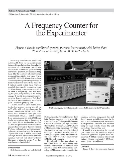
The frequency counter in this project is connected to a commercial RF generator.<br />
Photo A shows <strong>the</strong> front end enclosure that I<br />
built. Ano<strong>the</strong>r important thing is to provide<br />
a path as close as 50 Ω as possible from <strong>the</strong><br />
Channel B connector (<strong>the</strong> high frequency<br />
channel) to <strong>the</strong> prescaler (LMX2326). I used<br />
a 0.1 inch trace on <strong>the</strong> circuit side. FR4 (fiber<br />
glass) material is a good choice <strong>for</strong> <strong>the</strong> board<br />
(although I have used phenolic material),<br />
with a ground plane on one side and <strong>the</strong> circuit<br />
on <strong>the</strong> o<strong>the</strong>r. Use surface mount devices<br />
(SMD) <strong>for</strong> both channels.<br />
The original unit has four printed circuit<br />
boards: front end, power supply, time<br />
base and control board, and all boards were<br />
assembled using 0805 surface mount technology<br />
(SMT) components, except <strong>for</strong> <strong>the</strong><br />
processor and some components here and<br />
<strong>the</strong>re. I suggest a shielded enclosure <strong>for</strong> <strong>the</strong><br />
unit, to reduce electromagnetic interference<br />
(EMI) problems. The main box was built<br />
using one sided phenolic boards. The lead<br />
photo shows <strong>the</strong> assembled unit.<br />
It would be wise to orient <strong>the</strong> external<br />
sync connector to <strong>the</strong> outside — a quick<br />
connection type would be great, like a subminiature<br />
B (SMB) connector. I have used<br />
ordinary (though good quality) BNC connectors<br />
<strong>for</strong> <strong>the</strong> channel inputs.<br />
Circuitry<br />
Figure 1 shows <strong>the</strong> schematic diagram<br />
10 QEX – May/June 2010 Reprinted with permission © ARRL
of <strong>the</strong> front end circuit board. On <strong>the</strong> low<br />
frequency channel (Channel A), <strong>the</strong> FET<br />
provides high input impedance. It is followed<br />
by two amplifiers and a Schmitt trigger<br />
inverter that “digitizes” <strong>the</strong> signal. The high<br />
frequency channel (Channel B) input has a<br />
3 dB pad that helps to define <strong>the</strong> 50 Ω path<br />
between <strong>the</strong> connector and <strong>the</strong> monolithic<br />
amplifier. The LMX2326 is a low power<br />
phase locked loop (PLL), but only its prescaler<br />
is used here. Channel A has an overall<br />
sensitivity of about 25 mV RMS from 30 Hz<br />
to 55 MHz, (from 0.2 Hz <strong>for</strong> square waves).<br />
Channel B has roughly <strong>the</strong> same sensitivity,<br />
from 55 MHz to 2.2 GHz. Above 2.2 GHz,<br />
<strong>the</strong> sensitivity is degraded to about 150 mV<br />
RMS at 2.8 GHz. Careful layout <strong>for</strong> <strong>the</strong><br />
Channel B input could probably improve this<br />
behavior. The power supply of <strong>the</strong> channel<br />
not selected is switched off, to avoid interaction<br />
and to minimize power consumption.<br />
Maximum levels are 50 V peak <strong>for</strong> Channel<br />
A and +16 dBm <strong>for</strong> Channel B.<br />
The power supply (see Figure 2) was provided<br />
with a protection circuit at <strong>the</strong> power<br />
Photo A — It is best to build <strong>the</strong> counter front end circuitry into a shielded enclosure.<br />
Figure 1 — Here is <strong>the</strong> schematic diagram of <strong>the</strong> counter front end circuitry.<br />
Reprinted with permission © ARRL<br />
QEX – May/June 2010 11
(A)<br />
(B)<br />
(C)<br />
Figure 2 — The schematic diagram at Part A shows <strong>the</strong> counter power supply. Part B shows <strong>the</strong> top of <strong>the</strong> supply circuit board and Part C<br />
shows <strong>the</strong> bottom of <strong>the</strong> board, with circuit traces and SMT components.<br />
12 QEX – May/June 2010 Reprinted with permission © ARRL
input (9-12 V dc) that can be omitted if you<br />
have a tidy workbench and well behaved<br />
friends. The fuse will blow if you have an<br />
internal short circuit, if <strong>the</strong> supply leads are<br />
inverted or in <strong>the</strong> case of an overvoltage<br />
(>15 V dc). The power supply module generates<br />
5 V dc <strong>for</strong> general use, switchable 5 V dc<br />
<strong>for</strong> <strong>the</strong> front end channels and an adjustable<br />
voltage <strong>for</strong> <strong>the</strong> display back light.<br />
Figure 3 shows <strong>the</strong> schematic diagram of<br />
<strong>the</strong> internal time base, along with photos of<br />
<strong>the</strong> top and bottom of my circuit board. In <strong>the</strong><br />
original counter, I used a commercial adjustable<br />
oscillator, disassembled from a piece<br />
of old NEC equipment. I suggest <strong>the</strong> twotransistor<br />
circuit of Figure 5 <strong>for</strong> <strong>the</strong> internal<br />
time base, noting that <strong>the</strong> capacitors that are<br />
part of <strong>the</strong> oscillator are all NPØ, including<br />
<strong>the</strong> trimmer — SMT fixed capacitors would<br />
be fine. I have tested this circuit with an<br />
ordinary crystal, and <strong>the</strong> circuit worked very<br />
well. It would be a very good idea to enclose<br />
<strong>the</strong> circuit with a small shielding box. When<br />
you connect an external time base signal<br />
with 1 Vpp, <strong>the</strong> internal reference is automatically<br />
switched off.<br />
The PIC16F876A processor is <strong>the</strong> heart<br />
of <strong>the</strong> counter and it also controls <strong>the</strong> display,<br />
which requires much less power <strong>for</strong> its blue<br />
back light than <strong>the</strong> older green ones.<br />
Adjustments<br />
There are only four adjustments in <strong>the</strong><br />
counter. First of all, adjust <strong>the</strong> trimpot on <strong>the</strong><br />
processor board <strong>for</strong> <strong>the</strong> best display contrast.<br />
(A)<br />
(B)<br />
(C)<br />
Figure 3 — Part A is <strong>the</strong> time base schematic diagram <strong>for</strong> <strong>the</strong> circuit I used. Part B shows <strong>the</strong> top of my circuit board, with <strong>the</strong> commercial<br />
10 MHz module. Part C shows <strong>the</strong> bottom of my circuit board, with <strong>the</strong> circuit traces and SMT components.<br />
Reprinted with permission © ARRL<br />
QEX – May/June 2010 13
Figure 4 — The PIC 16F876A controller, shown in this schematic diagram, is <strong>the</strong> heart of <strong>the</strong> counter.<br />
Now connect a 25 mV RMS, 50 MHz signal<br />
to Channel A and adjust <strong>the</strong> trimpot at<br />
<strong>the</strong> input of <strong>the</strong> inverter until this frequency<br />
(or close) is steadily shown on <strong>the</strong> display.<br />
Increase <strong>the</strong> frequency up to 55 MHz, always<br />
tweaking this trimpot.<br />
Now connect a reference signal (10 MHz,<br />
<strong>for</strong> instance) to <strong>the</strong> Channel A input. Adjust<br />
<strong>the</strong> internal time base trimmer until <strong>the</strong> display<br />
shows <strong>the</strong> exact frequency, down to<br />
units of Hz. Note that <strong>the</strong> precision of this<br />
calibration adjustment will depend on <strong>the</strong><br />
precision of this external reference signal.<br />
Finally adjust <strong>the</strong> power supply module<br />
trimpot <strong>for</strong> a com<strong>for</strong>table display back light<br />
— if you intend to use this counter frequently<br />
with batteries, it would be wise to adjust to<br />
<strong>the</strong> minimum voltage that will still give good<br />
readability.<br />
Software and Operation<br />
Excluding <strong>the</strong> ON-OFF switch, this is<br />
a one-button-only instrument — pressing<br />
and releasing <strong>the</strong> MODE button will give<br />
<strong>the</strong> SCROLL command, and pressing and<br />
holding <strong>the</strong> button will give <strong>the</strong> ENTER<br />
command. If you are in <strong>the</strong> main display,<br />
scrolling will toggle between Channel A<br />
Figure 5 — This 10 MHz reference oscillator can be used as a reference oscillator <strong>for</strong><br />
<strong>the</strong> counter.<br />
14 QEX – May/June 2010 Reprinted with permission © ARRL
and B and ENTER will take you to <strong>the</strong><br />
main menu. The following choices will be<br />
shown: gate options, period measurements<br />
and offset.<br />
Gate options: Select <strong>the</strong> gate time —<br />
0.01, 0.1, 1 or 10 seconds. This is <strong>the</strong> time <strong>the</strong><br />
gate will be open <strong>for</strong> <strong>the</strong> measurement. Faster<br />
measurements will give less precision.<br />
Period: When you measure frequency,<br />
<strong>the</strong> gate will be kept open <strong>for</strong> a defined extension<br />
of time and <strong>the</strong> events will be counted —<br />
on <strong>the</strong> o<strong>the</strong>r hand, when you measure period,<br />
two subsequent events will respectively open<br />
and close <strong>the</strong> gate, and <strong>the</strong> time between <strong>the</strong><br />
events will be measured. For this reason,<br />
measuring <strong>the</strong> period of low frequency signals<br />
will lead to more accurate results. You<br />
can measure very low frequency signals<br />
using this technique, and <strong>the</strong> result can be<br />
shown as frequency or as time. Remember<br />
that <strong>Frequency</strong> = 1 / Period. To leave <strong>the</strong><br />
Period mode and start <strong>the</strong> <strong>Frequency</strong> mode,<br />
just choose a gate time.<br />
Offset: Here you can add or subtract a<br />
frequency to <strong>the</strong> signal present at any input.<br />
There are some predefined frequencies you<br />
can choose, related to <strong>the</strong> IF channel of simple<br />
rigs, or you can use <strong>the</strong> “Extern” option:<br />
just input <strong>the</strong> offset frequency and choose<br />
this option. Example 1: suppose you have a<br />
40 m (7 MHz to 7.1 MHz) CW rig, a 4 MHz<br />
IF filter and a 3 to 3.1 MHz VFO. In this case,<br />
connect <strong>the</strong> counter to <strong>the</strong> VFO and choose<br />
plus 4 MHz.<br />
Example 2: Now you have <strong>the</strong> same<br />
band but a 10.7 MHz IF and <strong>the</strong> VFO ranging<br />
from 3.7 to 3.6 MHz. This time choose<br />
a –10.7 MHz offset, and everything will be<br />
just fine. The software will take care of <strong>the</strong><br />
negative values and will show <strong>the</strong> correct frequency<br />
of <strong>the</strong> signal at <strong>the</strong> antenna.<br />
There are many options you can use to<br />
load <strong>the</strong> hex file into <strong>the</strong> processor. Some of<br />
<strong>the</strong>m (both software and hardware options)<br />
have been shared among Internet users.<br />
Particularly, I have downloaded <strong>the</strong> MPLAB<br />
IDE software from <strong>the</strong> Microchip Web site<br />
(IDE stands <strong>for</strong> Integrated Development<br />
Environment), because it has interesting<br />
tools <strong>for</strong> <strong>the</strong> developer and I have a compatible<br />
programmer.<br />
A Word of Caution<br />
This counter was designed <strong>for</strong> amateur<br />
use and I have purposely pushed <strong>the</strong> limits of<br />
<strong>the</strong> processor and prescaler to reach a desired<br />
per<strong>for</strong>mance. I have tested <strong>the</strong> circuit with<br />
samples I had, analyzing <strong>the</strong> circuit behavior<br />
with frequencies even higher than those<br />
stated here and I would expect <strong>the</strong> same<br />
per<strong>for</strong>mance <strong>for</strong> average chips. As a matter<br />
of fact, two more prototypes were assembled<br />
with o<strong>the</strong>r chips, leading to same results.<br />
Never<strong>the</strong>less, if you don’t want to step into<br />
<strong>the</strong> dark side of <strong>the</strong> <strong>for</strong>ce and/or don’t care<br />
about <strong>the</strong> world above 550 MHz, replace <strong>the</strong><br />
LMX2326 with an LMX2306 (same pinout).<br />
The software, in this case, has to be changed<br />
and <strong>the</strong> channel B sensitivity will be around<br />
5 mV RMS, from 25 MHz up. I suggest, in<br />
this case, that you replace <strong>the</strong> original front<br />
end pad with a 9 dB one, resulting in an overall<br />
sensitivity better than 10 mV RMS. The<br />
hex program files <strong>for</strong> both versions are available<br />
<strong>for</strong> download from <strong>the</strong> ARRL QEX files<br />
Web site. (See Note 1.)<br />
Final words<br />
I have been using this counter <strong>for</strong> over a<br />
year, and it is extremely useful, toge<strong>the</strong>r with<br />
o<strong>the</strong>r home built equipment I have made.<br />
Many concepts used here were derived from<br />
good technical literature and research on<br />
<strong>the</strong> Internet, especially concerning component<br />
data sheets. 2, 3 The design of this counter<br />
was also possible due to good friends:<br />
Delson, PY2DME, helped me with measurements<br />
above 1 GHz. Eduardo, PY2GNZ,<br />
assembled and tested prototypes and Jorge,<br />
PY2PVT, made <strong>the</strong> circuit boards.<br />
During <strong>the</strong> final stages of preparing this<br />
issue of QEX <strong>for</strong> <strong>the</strong> printer, I discovered that<br />
National Semiconductor recently discontinued<br />
production of <strong>the</strong> LMX2306/2316/2326<br />
family. While <strong>the</strong>se chips are still available<br />
from some sources, stock will be limited<br />
and <strong>the</strong>y may become scarce in <strong>the</strong> near<br />
future. I learned that <strong>the</strong> Analog Devices<br />
ADF4116/4117/4118 family of ICs appear<br />
to be equivalent, in terms of specifications,<br />
functions, pinouts and packages, but<br />
I can’t be sure that <strong>the</strong>y will work with <strong>the</strong><br />
same software, and provide <strong>the</strong> same per<strong>for</strong>mance<br />
without assembling a new set of<br />
counter boards and testing <strong>the</strong>m. The Analog<br />
Devices ICs are available from Digi-Key. I<br />
would like to note that last year <strong>the</strong> LMX<br />
family of parts were easy to find at very good<br />
prices, but <strong>the</strong> market is very dynamic, and<br />
<strong>the</strong> manufacturers only want to produce parts<br />
<strong>for</strong> which <strong>the</strong>re is a very large market.<br />
Notes<br />
1<br />
The author’s hex code program file is available<br />
<strong>for</strong> download from <strong>the</strong> ARRL Web site<br />
QEX files area. Go to www.arrl.org/qex<br />
files/ and look <strong>for</strong> <strong>the</strong> file 5x10_Fernandes.<br />
zip.<br />
2<br />
Wes Hayward, W7ZOI, Rick Campbell,<br />
KK7B, Bob Larkin, W7PUA, Experimental<br />
Methods in RF Design, ARRL, ARRL Order<br />
No. 9239, $49.95. ARRL publications are<br />
available from your local ARRL dealer or<br />
from <strong>the</strong> ARRL Bookstore. Telephone toll<br />
free in <strong>the</strong> US: 888-277-5289, or call 860-<br />
594-0355, fax 860-594-0303; www.arrl.org/<br />
shop; pubsales@arrl.org.<br />
3<br />
Bob Okas, W3CD, “The Norcal <strong>Frequency</strong><br />
<strong>Counter</strong> – FCC-1,” ARRL, QST, Sep 2006,<br />
pp 28-32.<br />
Rubens R. Fernandes earned a BS in<br />
Electrical Engineering in 1970, and worked<br />
<strong>for</strong> about 31 years in <strong>the</strong> telecommunications<br />
industry, in research, design and production.<br />
He retired about 5 years ago. He has been a<br />
licensed Amateur <strong>Radio</strong> operator since 1979,<br />
and held <strong>the</strong> call sign PY2QE while living in<br />
Brazil. He is a CW enthusiast. He now dedicates<br />
his spare time to home brewing small<br />
transceivers and test equipment. He has a<br />
small workshop that includes mechanical, electrical,<br />
software and silk-screening facilities.<br />
Reprinted with permission © ARRL<br />
QEX – May/June 2010 15