RIGblaster Advantage Owner's Manual - West Mountain Radio
RIGblaster Advantage Owner's Manual - West Mountain Radio
RIGblaster Advantage Owner's Manual - West Mountain Radio

Create successful ePaper yourself
Turn your PDF publications into a flip-book with our unique Google optimized e-Paper software.
<strong>RIGblaster</strong><br />
<strong>Advantage</strong><br />
www.westmountainradio.com<br />
1020 Spring City Drive<br />
Waukesha, WI 53186<br />
262-522-6503<br />
sales@westmountainradio.com<br />
©2015 <strong>West</strong> <strong>Mountain</strong> <strong>Radio</strong>, All rights reserved. All trademarks are<br />
the property of their respective owners.
Table of Contents<br />
Introduction<br />
About the <strong>RIGblaster</strong> <strong>Advantage</strong> .................... 4<br />
About the <strong>RIGblaster</strong> DVD ........................ 5<br />
Digital-Mode Operating ........................... 5<br />
Package Contents ................................. 6<br />
Controls, Connections and Features<br />
Choosing the Correct ISC ......................... 8<br />
Software Driver Installation ........................10<br />
Windows, Linux & Mac Drivers .....................10<br />
How to Renumber the <strong>RIGblaster</strong> <strong>Advantage</strong> COM port ..14<br />
Transceiver Connections ..........................15<br />
Required Connections ............................15<br />
Optional Connections ............................15<br />
<strong>RIGblaster</strong> Settings<br />
Audio Levels ...................................16<br />
PTT (Keying your radio) ..........................18<br />
Morse (CW) Operation ...........................18<br />
RTTY (FSK) Operation ...........................19<br />
CAT ..........................................20<br />
Transceiver Settings<br />
Operation Mode .................................21<br />
Recieve Settings ................................21<br />
Transmit Settings ................................22<br />
Software Configuration<br />
FLDigi (Multiple Digital Modes) .....................23<br />
Airlink Express (PSK31, RTTY & MFSK-16) ...........26<br />
MMTTY (RTTY FSK) .............................29<br />
MRP40 (Morse Code) ............................32<br />
JT65-HF: (JT Modes) ............................34<br />
Winlink 2000 with RMS Express (WinMOR) ...........37<br />
UZ7HO Sound Modem (Packet <strong>Radio</strong>) ...............40<br />
MMSSTV (Analog SSTV) .........................44<br />
Easy Pal (Digital SSTV) ..........................46<br />
FreeDV (Digital HF Voice) .........................49<br />
Ham <strong>Radio</strong> Deluxe & DM-780 ......................53
Reference<br />
<strong>RIGblaster</strong> <strong>Advantage</strong> Connection Diagrams ..........58<br />
Icom CI-V CAT Cable Schematic ...................58<br />
ISC & Jumper Wiring .............................59<br />
Using the <strong>RIGblaster</strong> <strong>Advantage</strong> as a Microphone Patch Box ..63<br />
Using the <strong>West</strong> <strong>Mountain</strong> <strong>Radio</strong> COM Port Splitter ......64<br />
P2 Jumper .....................................64<br />
Digital-Modes, Software and Frequencies ............65<br />
Troubleshooting .................................66<br />
<strong>Radio</strong> Hook-up Diagrams .........................69<br />
<strong>West</strong> <strong>Mountain</strong> <strong>Radio</strong><br />
3<br />
Operating <strong>Manual</strong>
Introduction<br />
About The <strong>RIGblaster</strong> <strong>Advantage</strong><br />
We understand you have a choice when buying Amateur <strong>Radio</strong> products<br />
and we would like to take a moment to thank you for choosing <strong>West</strong><br />
<strong>Mountain</strong> <strong>Radio</strong>. The <strong>RIGblaster</strong> <strong>Advantage</strong> has been designed with<br />
you, the digital-mode operator in mind. It has many outstanding features<br />
which will at the same time enhance and simplify your operating. Some<br />
of the features of the <strong>RIGblaster</strong> <strong>Advantage</strong> which put it ahead of the<br />
competition include;<br />
• COM port push-to-talk (PTT) keying.<br />
• A high-quality built-in USB sound card with level controls (both RX<br />
& TX) on the front panel.<br />
• Pre-wired Instant Setup Connectors – no more complex jumper<br />
wiring!<br />
• Rig-control (CAT/CI-V).*<br />
• FSK jack for operating FSK RTTY.**<br />
• CW keying jack for operating Morse Code.<br />
• Digital VOX with adjustable delay.<br />
• Separate audio jacks for received and transmitted audio.<br />
• Foot-switch PTT input.<br />
• USB virtual serial port with RS-232C externalization<br />
• TX inhibit switch.<br />
Connection to your computer is made very simple with the supplied USB<br />
cable. We will go into connecting up your <strong>RIGblaster</strong> <strong>Advantage</strong> in the<br />
first chapter so do not hook it up right away.<br />
Please read through this manual first (especially the driver installation<br />
section) and you will find the <strong>RIGblaster</strong> <strong>Advantage</strong> will provide you with<br />
many years of reliable service and enjoyment.<br />
* Rig control is only available on certain transceivers.<br />
** FSK requires the transceiver to have a dedicated RTTY mode, an optional<br />
FSK cable and the software must support serial FSK.<br />
<strong>West</strong> <strong>Mountain</strong> <strong>Radio</strong><br />
4<br />
Operating <strong>Manual</strong>
About the <strong>RIGblaster</strong> DVD<br />
The supplied DVD is mostly a collection of various digital-mode software<br />
programs for use with sound card interfaces like the <strong>RIGblaster</strong><br />
<strong>Advantage</strong>.<br />
The programs contained on the disc were not written by <strong>West</strong> <strong>Mountain</strong><br />
<strong>Radio</strong>. Some are completely free while others are commercial. We have<br />
however tested our products on the majority of them.<br />
Amateur radio software is constantly evolving and we encourage you to<br />
visit the various authors websites to check for updates for software you<br />
wish to use.<br />
We maintain a list of website addresses for the software we place onto<br />
the DVD (as best we can) and you can access this page from:<br />
http://www.westmountainradio.com/content.php?page=links<br />
Introduction To Digital-Mode Operating<br />
Most modern digital-modes can be operated on the <strong>RIGblaster</strong><br />
<strong>Advantage</strong>. Some of these may already be familiar to you. For instance<br />
PSK31, JT65 & RTTY are very commonly heard on the bands.<br />
If you have the ability try tuning to 14.070MHz (USB) and chances<br />
are you will hear multiple PSK31 QSOs taking place. Moving up to<br />
14.073MHz you may hear the tones of the MFSK modes such as Olivia,<br />
Contestia, Thor and MFSK-16. You will also find the “cricket-like” chirping<br />
of Feld Hell.<br />
Tune to 14.073MHz you may hear the tones of the MFSK modes such as<br />
Olivia, Contestia, Thor and MFSK-16. You will also find the “cricket-like”<br />
chirping of Feld Hell.<br />
Tune to 14.076MHz and you will hear JT65 signals. Going up another<br />
10KHz lands you right in a very popular RTTY segment. Moving up<br />
through 14.100MHz you should hear packet networks, WinMOR and<br />
the wider band digital modes signals such as MT63, ALE and Pactor.<br />
14.230MHz (USB) yields a very active SSTV (Slow Scan TV) frequency.<br />
This is traditional analog SSTV. Another 3KHz up (14.233MHz) is the<br />
main watering-hole of digital SSTV enthusiasts<br />
14.230MHz (usb) yields a very active SSTV (Slow Scan TV) frequency.<br />
This is traditional analog SSTV. Another 3KHz up (14.233MHz) is the<br />
main watering-hole of digital SSTV enthusiasts.14.236MHz is currently<br />
very popular with the digital voice experimenters using FreeDV software.<br />
It is worth noting there are some modes in use which cannot be used<br />
with the <strong>RIGblaster</strong> <strong>Advantage</strong> (nor any sound-card based interface).<br />
<strong>West</strong> <strong>Mountain</strong> <strong>Radio</strong><br />
5<br />
Operating <strong>Manual</strong>
These are the arq modes Pactor, G-TOR, Amtor and Clover.<br />
These modes require very precise timing cycles which Windows is unable<br />
to deliver. Amtor, G-TOR and Clover are very seldom used these days but<br />
Pactor is commonly employed for mail messaging using the Winlink 2000<br />
system.<br />
In practice this is not much of a limitation as the RMS Express software<br />
(using WinMOR) makes mail/e-mail messaging simple using the <strong>RIGblaster</strong><br />
<strong>Advantage</strong>.<br />
Many digital-modes (such as PSK31) will work far down into the noise<br />
level. It is not uncommon to see copy on your screen even when you have<br />
difficulty hearing the signal on your speaker.<br />
This also implies you do not need to run high power levels during normal<br />
conditions and for most digital-modes you will find 20-40W ample. In fact,<br />
running close to maximum output on your radio is self-defeating. In this<br />
case you stand a very good chance of having a spread-out badly distorted<br />
signal (think QRM!) and you may even damage your rig on long overs as<br />
many transceivers are not designed to run high duty-cycle transmissions for<br />
extended periods.<br />
At the back of this manual you will find a simple chart of digital-modes,<br />
software and frequencies to try. These are just suggestions but will help you<br />
get started navigating the world of HF digital-modes.<br />
Package Contents<br />
The following is a list of the contents for the <strong>RIGblaster</strong> <strong>Advantage</strong>. Verify<br />
that all the following items were included:<br />
QTY ITEM<br />
1 <strong>RIGblaster</strong> <strong>Advantage</strong><br />
1 Owner’s <strong>Manual</strong><br />
7 Instant Setup Connectors<br />
8 Single Pin White Jumpers<br />
5 Mini Blue Shunt Jumpers<br />
4 #6 Black Metal Screws (*for cover)<br />
4 Adhesive Pads and Rubber Feet<br />
1 Microphone Cable (RJ-45 to 8 Pin Screw-On<br />
1 1/8” Stereo Mini Plug Cable<br />
1 USB (A/B) Cable<br />
1 DVD<br />
*The <strong>RIGblaster</strong> <strong>Advantage</strong> cover is loose so you may easily remove it to<br />
install jumpers.<br />
<strong>West</strong> <strong>Mountain</strong> <strong>Radio</strong><br />
6<br />
Operating <strong>Manual</strong>
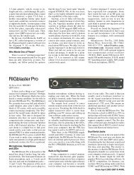
Controls, Connections And Features<br />
Receive audio level (Use in conjunction<br />
with computer audio level<br />
Transmit audio level (Use in<br />
conjunction with computer<br />
volume level<br />
If VOX enabled, controls length of time<br />
transmit is active<br />
PTT Software Config COM: RTS Control<br />
PTT DTGR Controls CW/FSK off: computer<br />
can never activate PTT or CW/<br />
FSK VOX: PTT and CW/FSK activated<br />
automatically by audio.<br />
USB LED (lights when unit is powered.<br />
Will blink when software is<br />
receiving or transmitting audio<br />
Microphone input for 8 pin round mic<br />
(Mic output with RJ45 connector radio)<br />
PTT LED (lights when software<br />
activates transmits)<br />
FSK/CW LED (lights when software accesses serial<br />
DTR line for FSK/CW keying. Also lights in VOX<br />
mode and indicates signal level)<br />
USB to interface (Read driver<br />
install before connecting.<br />
CAT RIG Control at RS232 Levels<br />
PTT in/out RCA Connector (used with footswitch<br />
or other PTT switch or connection.<br />
Microphone output for 8 pin<br />
round mic:used with cable<br />
(Mic input with RJ45 connector<br />
radio<br />
Audio line input (outgoing audio<br />
from your radio connects here<br />
CAT/CI-V rig control (Connects to<br />
radio with accessory cable)<br />
CW/FSK keying output (connects<br />
to radio keying input<br />
Computer transmitted audio allows<br />
you to monitor transit audio from PC<br />
<strong>Radio</strong> transmitted audio (allows<br />
you to monitor audio received<br />
by radio)<br />
<strong>West</strong> <strong>Mountain</strong> <strong>Radio</strong><br />
7<br />
Operating <strong>Manual</strong>
Choosing the Correct ISC<br />
Configuring the <strong>RIGblaster</strong> <strong>Advantage</strong> with a transceiver is very simple<br />
by use of the Instant Setup Connectors (ISC). These take the place of<br />
jumper wiring for many common radios.<br />
Each ISC is respectively identified: Icom Round Metal, Icom RJ45<br />
Modular, Yaesu Round Metal, Yaesu Round Metel – Isolated, Yaesu<br />
RJ45 Modular, Kenwood Round Metal and Kenwood RJ45 Modular.<br />
Depending on the transceiver in use, one of these ISCs will need to be<br />
installed inside the <strong>RIGblaster</strong> <strong>Advantage</strong> before use. They take care<br />
of all the microphone connection wiring that previously was done by<br />
installing jumper wires and shunts. If using a non-standard microphone<br />
wiring, jumper wires and and blue shunts have been provided in the<br />
package contents.<br />
The ISCs cover most popular brands and models of radios.<br />
Observe the microphone connector on the radio. Typically it will be one of<br />
two types – either an 8-pin round metal connector or an RJ- 45 “square”<br />
modular jack. The <strong>RIGblaster</strong> <strong>Advantage</strong> is designed to interface the<br />
transceiver through the microphone jack. Be sure to select the ISC that<br />
matches the connector on the radio.<br />
Chart of ISCs For Some Common <strong>Radio</strong>s:<br />
Manufacturer Model ISC<br />
Icom<br />
All 8 pin round mic jack radios (e.g., IC-746, IC-756/ Icom 8 Pin Round<br />
Pro/III,IC-7600)<br />
Icom<br />
All RJ-45 modular mic jack radios (e.g., IC-706, IC- Icom RJ-45 Modular<br />
7000)<br />
Yaesu<br />
All older 8 pin round mic jack radios (e.g., FT-840, FT- Yaesu 8 Pin Round<br />
757, FT-920)<br />
Yaesu<br />
All newer 8 pin round mic jack radios (e.g., FT-950, FT- Yaesu 8 Pin Round- Isolated<br />
2000, FTDX-3000, FTDX-5000, FTDX-9000)<br />
Yaesu<br />
All RJ-45 modular mic jack radios (e.g., FT-817, FT- Yaesu RJ-45 Mdular<br />
857, FT-897, FT-450)<br />
Kenwood All 8 pin round mic jack radios (e.g. TS-570, TS-2000, Kenwood 8 Pin Round<br />
TS-590S, TS-990S)<br />
Kenwood Most RJ-45 modular mic jack radios (e.g. TM-V71) Kenwood RJ-45 Modular<br />
Elecraft K3 & K2 use the same mic jack as Kenwood Kenwood 8 Pin Round<br />
Ten Tec Omni VII & Orion II use the same mic jack as newer Yaesu 8 Pin Round – Isolated<br />
Yaesu radios<br />
Flex<br />
Flex 1500 and 3000 use the same mic jack as Yaesu Yaesu RJ-45 Modular<br />
RJ-45 radios<br />
Flex<br />
Flex 5000 and 6000 series use the same mic jack as<br />
newer Yaesu radios<br />
Yaesu 8 Pin Round - Isolated<br />
<strong>West</strong> <strong>Mountain</strong> <strong>Radio</strong><br />
8<br />
Operating <strong>Manual</strong>
Locate the correct ISC for the radio and install it on the ISC header (2<br />
rows of 13 pins) located inside the <strong>RIGblaster</strong> <strong>Advantage</strong> ensuring pin 1<br />
on the ISC matches pin 1 on the header.<br />
Example: Installation of a Kenwood RJ45 Modular ISC inside the<br />
<strong>RIGblaster</strong> <strong>Advantage</strong>. Notice the orientation of the ISC<br />
and the location of pin 1.<br />
Some radios use a 4-pin round microphone connector, these include<br />
older Kenwood and Yaesu transceivers and some Ten-Tec radios. An<br />
adapter will be needed to use the <strong>RIGblaster</strong> <strong>Advantage</strong> with these<br />
radios. The correct adapter is SKU 58136-1000 and available online for<br />
purchase.<br />
<strong>Radio</strong>s with 6 pin microphone connectors such as the Yaesu FT-100D<br />
will require our optional “Yaesu Modular 6” cable (SKU 58118-982). This<br />
cable comes with a jumper diagram and a resistor for correct operation.<br />
<strong>West</strong> <strong>Mountain</strong> <strong>Radio</strong><br />
9<br />
Operating <strong>Manual</strong>
Software Driver Installation<br />
The <strong>RIGblaster</strong> <strong>Advantage</strong> when properly installed in Windows, Linux<br />
or Macintosh operating systems will provide two new hardware devices;<br />
a serial port and a sound-device.<br />
After the drivers installation has finished, the green led marked “USB”<br />
on the front of the <strong>RIGblaster</strong> <strong>Advantage</strong> will be illuminated. During<br />
installation, the red “XMIT” led may flicker a few times. This is normal<br />
and does not indicate a problem.<br />
The green “USB” led will blink when the <strong>Advantage</strong> sound card is<br />
in use and remain solid when idle. Blinking does not indicate any<br />
fault!<br />
Linux Installation<br />
<strong>West</strong> <strong>Mountain</strong> <strong>Radio</strong> drivers have been included in the Linux kernel<br />
since version 3.8.4. Most recent distributions should have no problem<br />
automatically recognizing the <strong>RIGblaster</strong> <strong>Advantage</strong>.<br />
The following notes are for Ubuntu but may also apply to derived<br />
distributions.<br />
You can find the assigned serial device by opening a terminal and<br />
typing:<br />
ls -l /dev/ttyUSB*<br />
This should return a display similar to the one below:<br />
crw-rw---- 1 root dialout 188, 0 Sep 30 13:49 /dev/ttyUSB0<br />
If the group “dialout” is not listed in the output you will need to add your<br />
username to that group. This is the most common reason why rigcontrol<br />
or PTT won’t function!<br />
Use the following command:<br />
sudo usermod -a -G dialout <br />
where is your linux user name.<br />
Then log off and log back on for the changes to take effect.<br />
<strong>West</strong> <strong>Mountain</strong> <strong>Radio</strong><br />
10<br />
Operating <strong>Manual</strong>
If you have more than one USB serial device on your system you can<br />
use the following command to determine which ttyUSB device number is<br />
assigned to the <strong>RIGblaster</strong>:<br />
ls -l /dev/serial/by-id | grep ‘<strong>RIGblaster</strong>’<br />
This will return a display similar to:<br />
lrwxrwxrwx 1 root root 13 Oct 7 05:42 USB-Silicon_Labs_<strong>West</strong>_<br />
<strong>Mountain</strong>_<strong>Radio</strong>_<strong>RIGblaster</strong>_<strong>Advantage</strong>_d5b25d6b-if00-port0 ->../../<br />
ttyUSB0<br />
In this case ttyUSB0 is assigned to the <strong>RIGblaster</strong>.<br />
To find the <strong>RIGblaster</strong> <strong>Advantage</strong> sound card playback device type the<br />
following: aplay -l | grep ‘<strong>RIGblaster</strong>’<br />
To find the <strong>RIGblaster</strong> <strong>Advantage</strong> sound card recording device use this:<br />
arecord -l | grep ‘<strong>RIGblaster</strong>’<br />
For older distributions and troubleshooting visit the following support<br />
page: http://www.westmountainradio.com/adv/drv/linux<br />
Macintosh Installation<br />
The <strong>RIGblaster</strong> <strong>Advantage</strong> will work with OS X 10.5 and above. Drivers<br />
and instructions are available online:<br />
http://www.westmountainradio.com/adv/drv/macosx<br />
Windows Installation<br />
You have two choices of automatic installation on Windows systems.<br />
Quick Method (For advanced Windows users running Vista,<br />
Windows 7 or Windows 8)<br />
As long as your computer is on-line, you can simply plug in the USB<br />
cable to your computer and the <strong>RIGblaster</strong> <strong>Advantage</strong>. This will trigger<br />
the “Found New Hardware Wizard” and you will be asked if you want to<br />
do an automatic install. Answer yes and allow Windows to connect to<br />
Microsoft Update to retrieve the signed drivers.<br />
You will be notified when the process is complete. This can take a few<br />
minutes so be patient.<br />
This method may not work on Windows XP or earlier versions of Windows.<br />
In this case you are advised to use the standard method of installation<br />
detailed below.<br />
<strong>West</strong> <strong>Mountain</strong> <strong>Radio</strong><br />
11<br />
Operating <strong>Manual</strong>
Standard Method (Recommended for most users)<br />
Do not attach the <strong>RIGblaster</strong> <strong>Advantage</strong>.<br />
Insert the DVD into your computer which should autoplay. You will be<br />
prompted the first time you insert this disk if you want to install the <strong>RIGblaster</strong><br />
Survey/Diagnostic Program. Answer yes to all steps and this will<br />
pre-load all <strong>West</strong> <strong>Mountain</strong> <strong>Radio</strong> drivers for you. After it has installed<br />
you may attach the <strong>RIGblaster</strong> <strong>Advantage</strong>.<br />
<strong>Manual</strong> Installation<br />
For those still using Windows 2000 or Windows 98 you will find a driver<br />
package available from http://www.westmountainradio.com/adv/drv/win2k<br />
In the case of Windows 98 it must be Windows 98SE and have all the<br />
Microsoft issued USB updates applied before it will work.<br />
After successful installation a good idea is to check Windows Device<br />
Manager and verify there is a new COM port and audio device.<br />
<strong>West</strong> <strong>Mountain</strong> <strong>Radio</strong><br />
12<br />
Operating <strong>Manual</strong>
Finding Device Manager in Windows XP:<br />
1. Open the Windows Control Panel (Start->Settings->Control Panel)<br />
2. Look for the System icon and double-click it.<br />
3. Choose the “Hardware” tab at the top and click the button marked<br />
“Device Manager”.<br />
Finding Device Manager in Windows 7:<br />
1. Open the Windows Control Panel (Start->Settings->Control Panel)<br />
2. Change Control Panel to “View By Small Icons”<br />
3. Click on the icon labeled “System”<br />
4. Click on the icon labeled “Device Manager”<br />
Finding Device Manager in Windows 8.1:<br />
1. Right-click on the “Windows button” (start menu) and choose “Device<br />
Manager” from the list.<br />
A window similar to the one shown here should appear. There will be a<br />
section called “Ports (COM & LPT)” which can be expanded to view by<br />
clicking on the + symbol to the left.<br />
Look for the entry <strong>West</strong> <strong>Mountain</strong> <strong>Radio</strong> <strong>RIGblaster</strong> <strong>Advantage</strong>. Immediately<br />
after this text, look for the COM port number in parenthesis (e.g.<br />
COM5).<br />
Make a note of this as it will be needed to configure digital mode software<br />
to use this COM port later.<br />
When expanding the section marked “Sound, video and game controllers”,<br />
notice the new entry labeled <strong>RIGblaster</strong> <strong>Advantage</strong> Audio (May be<br />
shown as USB Audio Device in Win XP or earlier).<br />
Windows may assign any number for the COM port. Windows typically<br />
treats COM1 to COM4 as special and does not normally use them for<br />
USB serial devices.<br />
Therefore, it is not recommended to renumber the <strong>RIGblaster</strong> <strong>Advantage</strong><br />
COM port to a value lower than 5 unless you have to.lers”, notice the<br />
new entry labeled <strong>RIGblaster</strong> <strong>Advantage</strong> Audio (Shown as USB Audio<br />
Device in Win XP or earlier).<br />
<strong>West</strong> <strong>Mountain</strong> <strong>Radio</strong><br />
13<br />
Operating <strong>Manual</strong>
How To Renumber The <strong>RIGblaster</strong> <strong>Advantage</strong> COM port<br />
If you find it necessary to renumber the <strong>RIGblaster</strong> <strong>Advantage</strong> COM port,<br />
e.g., for use with older software which requires a lower COM port number<br />
we have created an application to allow you to do this easily. It is part of<br />
the <strong>West</strong> <strong>Mountain</strong> <strong>Radio</strong> Diagnostic program “WMRDiagnostics” which<br />
is available on the supplied DVD. You may already have it installed if you<br />
followed the standard installation.<br />
Click the WMR icon on your system tray – it looks like this:<br />
A window will appear listing your computer serial ports and <strong>West</strong> <strong>Mountain</strong><br />
<strong>Radio</strong> <strong>RIGblaster</strong>s.<br />
Right-click over the <strong>RIGblaster</strong> <strong>Advantage</strong> entry and choose “Change<br />
Port #”.<br />
A new window will appear allowing you to enter a new COM port number.<br />
Make sure you choose one that isn’t already in use!<br />
<strong>West</strong> <strong>Mountain</strong> <strong>Radio</strong><br />
14<br />
Operating <strong>Manual</strong>
Transceiver Connections<br />
Now hook up the <strong>RIGblaster</strong> <strong>Advantage</strong> to the radio. Follow the steps<br />
in the next section and refer to the connection diagrams if necessary<br />
(located in the back of this manual).<br />
Required Connections<br />
1. Disconnect the microphone from the transceiver.<br />
2. Reconnect the microphone to the <strong>RIGblaster</strong> <strong>Advantage</strong>. Note: There<br />
will be only one connector on the <strong>Advantage</strong> that will mate with the<br />
microphone plug; either the 8-pin round metal socket mating to the front<br />
panel or the square RJ-45 connector mating to the rear panel.<br />
3. Connect the 8-pin (round) to RJ-45 (square) microphone cable,<br />
included in the package contents, to the transceiver’s microphone input<br />
socket. There will be only one end that will mate with the transceiver’s<br />
microphone socket.<br />
4. Connect the other end of the microphone cable to the <strong>RIGblaster</strong><br />
<strong>Advantage</strong>.<br />
5. Take the 1/8” inch stereo patch cable and connect one end to the<br />
transceiver’s speaker out (or headphone) jack. Note: If the transceiver<br />
uses a 1/4” jack, it will require use of 1/8” inch to 1/4” stereo adapter.<br />
6. The other end of the patch cable should be connected to the jack<br />
labeled LINE IN on the rear of the <strong>RIGblaster</strong> <strong>Advantage</strong>.If you have our<br />
optional FSK cable then you would not perform steps 5 and 6 above.<br />
Connect the flying lead marked “Audio” to the LINE IN jack.<br />
Optional Connections<br />
Additional jacks are provided on the rear of the <strong>RIGblaster</strong> <strong>Advantage</strong> for<br />
operation enhancement:<br />
1. Serial DB-9. This connector can be used to interface some<br />
transceivers that require RS-232C level CAT. Note: This serial connector<br />
is a hardware extension of the USB virtual serial port. All lines are<br />
connected but take note that some control lines are used by the<br />
<strong>RIGblaster</strong> <strong>Advantage</strong> for PTT & CW/FSK.<br />
2. CTL IN/OUT. This is a TTL level jack providing CI-V/CAT rig control.<br />
Many radios can be interfaced to this jack with a low-cost cable for<br />
complete rig control with suitable software.<br />
<strong>West</strong> <strong>Mountain</strong> <strong>Radio</strong><br />
15<br />
Operating <strong>Manual</strong>
3. CW/FSK. This jack can be used for serial port CW keying or FSK shift<br />
if your transceiver supports it.<br />
4. AUDIO OUT. This jack provides a transmitted audio output. Connect<br />
amplified computer speakers or a pair of mini earphones here for<br />
transmit monitoring.<br />
5. SPKR OUT. This jack provides a rig receive audio output. Connect an<br />
external speaker here only if not using our optional FSK cable.<br />
6. PTT IN/OUT. This RCA phono jack is primarily used for connection<br />
to a foot-switch for PTT. The contacts are in parallel with the <strong>Advantage</strong><br />
PTT relay (rated 30 VDC 2A max.) and in parallel with the transceiver’s<br />
microphone PTT line, and will float at the same voltage.<br />
<strong>RIGblaster</strong> Settings<br />
Audio Levels<br />
Proper audio level setting is crucial to successful digital-mode operation.<br />
The <strong>RIGblaster</strong> <strong>Advantage</strong> transmit audio level can be set by use of the<br />
Windows playback volume slider and the convenient front panel XMIT<br />
LEVEL control. Receive level can be set by the Windows recording<br />
volume slider and the front-panel RCV LEVEL control.<br />
It is recommended to set the <strong>RIGblaster</strong> <strong>Advantage</strong> audio device levels<br />
to 50% for both “recording” and “playback” within Windows. Fine tuning<br />
can then be made using the XMIT & RCV level controls on the front of<br />
the <strong>Advantage</strong>.<br />
It is important not to set the <strong>RIGblaster</strong> <strong>Advantage</strong> as the default<br />
Windows audio device. This will prevent any unintentional transmissions<br />
if operating in VOX mode (Windows audio-alerts, music etc).<br />
Note: Some older digital-mode software only uses the default sound card<br />
in Windows for output. If using such software be careful when assigning<br />
the default Windows sound-card to the <strong>Advantage</strong>. In this case, it is<br />
recommended to change the Windows sound scheme to silent.<br />
To access your Windows audio levels use the “Sound” icon in Control<br />
Panel and refer to the images shown below.<br />
You can also use the “Sound” program to assign which sound card is<br />
the default device by right-clicking a device (in this case the internal<br />
computer sound card) and choosing “Set as default device”.<br />
<strong>West</strong> <strong>Mountain</strong> <strong>Radio</strong><br />
16<br />
Operating <strong>Manual</strong>
Note: The <strong>RIGblaster</strong> sound card should not be set as the “default<br />
communication device” for either record or playback.<br />
If you find that transmit audio is too “hot” then try reducing the playback<br />
volume to about 10%. If that doesn’t help there is a single jumper in the<br />
<strong>Advantage</strong> which will further attenuate transmit volume by 20dB. It is<br />
located next to one of the audio transformers and should be shorted for<br />
the attenuator to be active.<br />
Setting The Playback (TX) Volume<br />
Setting The Record (RX) Volume<br />
<strong>West</strong> <strong>Mountain</strong> <strong>Radio</strong><br />
17<br />
Operating <strong>Manual</strong>
PTT (Keying Your <strong>Radio</strong>)<br />
On the front-panel of the <strong>RIGblaster</strong> <strong>Advantage</strong> there is a three position<br />
switch labeled TX. This controls how PTT is activated (the method by<br />
which the transceiver goes into transmit).<br />
Position 1 – COM<br />
The <strong>Advantage</strong> is under computer control and switches the transceiver<br />
between transmit and receive depending on the state of the serial port<br />
RTS control signal.<br />
Position 2 – OFF<br />
The <strong>Advantage</strong> is prevented from activating transmit on the transceiver.<br />
Note: The RCA foot-switch input is still active.<br />
Position 3 – VOX<br />
The <strong>Advantage</strong> contains circuitry which detects the presence of an audio<br />
transmit signal and automatically switches the transceiver into transmit.<br />
When the signal ends the transceiver is returned to receive mode.<br />
The VOX method of operation is suitable for many digital-modes and<br />
often simplifies software configuration. An example of this would be<br />
running a logging program (which requires exclusive use of the serial<br />
port to read frequency and mode) but having the ability to run a preferred<br />
PSK31 program simultaneously. Using VOX mode allows the PSK31<br />
software to key the rig without conflicting with the logging program.<br />
(Note: There is no need to use the transceiver VOX setting).<br />
Morse (CW) Operation<br />
The <strong>RIGblaster</strong> <strong>Advantage</strong> has two methods of sending Morse Code<br />
(CW).<br />
One method is using MCW (Modulated or Tone CW) in SSB or FM<br />
modes. Some computer software will only produce this type of CW.<br />
The second, and preferred, method is to use serial port keying:<br />
Connect a stereo patch cable from the <strong>RIGblaster</strong> <strong>Advantage</strong>’s CW/ FSK<br />
jack to the transceiver’s CW keying jack. This will permit Morse operation<br />
when using the radio’s CW mode with suitable software.<br />
This hardware CW keying is realized by use of the DTR control line on<br />
the COM port. Refer to the example of setting up CW keying using the<br />
MRP40 software shown later in this manual.<br />
<strong>West</strong> <strong>Mountain</strong> <strong>Radio</strong><br />
18<br />
Operating <strong>Manual</strong>
It is also possible to operate MCW in VOX mode, in which case the DTR<br />
circuit is logically OR’ed with PTT - the result is hardware keying from<br />
software which only has the MCW method available. Note: This is an<br />
excellent way of producing hard CW keying from the fldigi software.<br />
By using a dual 1/8 th inch stereo adaptor plug (or ‘Y’ splitter cable),<br />
connect the Morse Key in parallel with the CW jack. The output is open<br />
collector so is safe to use with contact-closure Morse Keys and modern<br />
“pull to ground” electronic keyers. This will allow to send computer Morse<br />
or use the key for maximum flexibility. Warning: Do not attempt this if<br />
your radio uses grid-block keying or cathode keying - you will destroy<br />
your <strong>Advantage</strong>!<br />
RTTY (FSK) Operation<br />
Similar to CW, there are two methods used to generate RTTY signals.<br />
Method one is AFSK RTTY being used in SSB mode. This relies on the<br />
software to generate the RTTY tones. Most digital-mode software will<br />
use this method.<br />
The other method, FSK RTTY, may also be used by some PC software.<br />
Only transceivers that have an RTTY mode and FSK shift input will work<br />
in this method. A special cable is required to interface from the CW/FSK<br />
jack on the <strong>RIGblaster</strong> <strong>Advantage</strong> to the FSK input on the transceiver.<br />
FSK shift input is controlled by the serial DTR line. Note: PTT is also<br />
required and provided by serial RTS.<br />
Refer to the MMTTY example later in this manual for an example of<br />
configuring FSK.<br />
FSK Cables Available From <strong>West</strong> <strong>Mountain</strong> <strong>Radio</strong>:<br />
SKU<br />
Used On<br />
58129-995 Icom radios with a 13 pin accessory jack<br />
(e.g., IC-706, IC-718, IC-7000)<br />
58129-994 Icom radios with an 8 pin accessory jack<br />
(e.g., IC-746, IC-756/Pro/II)<br />
58131-999 Kenwood radios with a 13 pin accessory jack<br />
(e.g., TS-2000)<br />
58131-998 Yaesu radios with a 4 pin ‘RTTY’ jack<br />
(e.g., FT-1000, FT-2000, FTDX-5000)<br />
58131-1517 Elecraft K3<br />
58131-1501 Yaesu radios with a 6 pin mini din FSK jack<br />
(e.g., FT-450, FT-950, FTDX-1200, FTDX-3000)<br />
<strong>West</strong> <strong>Mountain</strong> <strong>Radio</strong><br />
19<br />
Operating <strong>Manual</strong>
CAT Operation<br />
The <strong>RIGblaster</strong> <strong>Advantage</strong> is equipped with TTL and RS-232C<br />
level CAT. This makes it possible to use software for logging or<br />
radio control in addition to digital modes all through the same<br />
interface.<br />
Most modern radios have a CAT jack and with very few exceptions<br />
the <strong>RIGblaster</strong> <strong>Advantage</strong> can be connected to this via an optional<br />
cable for full computer control.<br />
The CAT jack on your radio is a serial interface (using TxD/RxD)<br />
which can receive instructions and send information back to your<br />
computer to be used with suitable software.<br />
The serial interface on the <strong>Advantage</strong> is implemented through<br />
same COM port we use for PTT and CW/FSK keying. It is<br />
externalized on the RIG CTL jack (TTL) or the DB-9 (RS-232C).<br />
Note: Both jacks cannot be in use at the same time.<br />
Hardware flow-control should not be used unless the <strong>RIGblaster</strong><br />
is operating in VOX as the radio will hold RTS high and cause the<br />
transmitter to be permanently in transmit mode.<br />
If your radio cannot disable flow-control (e.g., Kenwood with<br />
RS-232C) then we recommend you use our Kenwood CAT<br />
cable (SKU 58119-1432) which will allow proper operation of the<br />
<strong>RIGblaster</strong> in COM mode or use a separate USB to RS-232C<br />
adapter cable for CAT.<br />
CAT Cables Available From <strong>West</strong> <strong>Mountain</strong> <strong>Radio</strong>:<br />
SKU<br />
Used On<br />
58107-971 All CI-V equipped Icom radios (i.e., Icom radios<br />
with a “remote” jack)<br />
58108-972 Yaesu radios with an 8 pin mini din CAT jack<br />
(e.g., FT-817, FT-857,FT-897)<br />
58108-974 Yaesu radios with a 6 pin din CAT jack (e.g.,<br />
FT-736, FT-747, FT-767, FT-990)<br />
58119-1432 Kenwood radios with an RS-232C CAT jack<br />
(e.g. TS-480, TS-570, TS-2000)<br />
<strong>West</strong> <strong>Mountain</strong> <strong>Radio</strong><br />
20<br />
Operating <strong>Manual</strong>
In summary, the serial control lines used by the <strong>RIGblaster</strong><br />
<strong>Advantage</strong> are shown in the table below:<br />
Serial Line<br />
RTS<br />
DTR<br />
DTR<br />
TxD/RxD<br />
Function<br />
Transceiver PTT<br />
CW Keying (with CW software). <strong>Radio</strong> in<br />
CW mode.<br />
FSK Keying (with RTTY software). <strong>Radio</strong> in<br />
RTTY mode.<br />
CAT<br />
Transceiver Settings<br />
Operating Mode<br />
Most digital mode programs expect the transceiver to be used in usb<br />
(upper sideband).<br />
Traditionally, digital mode transmission was done in lsb (lower sideband)<br />
most modern software makes the assumption this is no longer the case.<br />
For some modes such as PSK31 (which is sideband independent) it<br />
actually makes no difference but to be “on the same page” with other<br />
operators you should choose usb unless you have good reason not to.<br />
The three exceptions to this would be real-keyed Morse Code (use CW<br />
mode), FSK generated RTTY (use RTTY mode) and AFSK RTTY (use<br />
LSB mode)<br />
Because the <strong>RIGblaster</strong> <strong>Advantage</strong> connects to a transceiver<br />
microphone jack it is important not to choose a “data” or “dig” mode on<br />
the radio. These modes typically expect transmit modulation through an<br />
accessory jack and will disable the microphone jack.<br />
Receive Settings<br />
For most digital modes setting your AGC (automatic gain control) to<br />
“auto” or “fast” is recommended. You may find some modes (e.g., Feld<br />
Hell & CW) will benefit from slow AGC action. There is no hard and fast<br />
rule for this so experimentation is advised.<br />
Receive filtering is normally left “wide open” but if you have the ability to<br />
alter your receive bandwidth in SSB mode you may do so which may<br />
help with co-channel interference in crowded conditions. When operating<br />
FSK RTTY you can use any narrow filtering you radio has available.<br />
If your radio has DSP noise reduction it should be turned off. The only<br />
modes which may benefit from some noise reduction are Feld Hell & CW.<br />
<strong>West</strong> <strong>Mountain</strong> <strong>Radio</strong><br />
21<br />
Operating <strong>Manual</strong>
Using DSP noise reduction (or DSP auto-notch filtering) will adversely<br />
affect reception of many digital signals. The transceiver’s NB button<br />
(Noise Blanker) ideally should be turned off but that may not be possible<br />
if you live in a high noise area.<br />
Transmit Settings<br />
The most important thing to avoid when transmitting digital modes is a<br />
distorted signal.<br />
This can happen when the drive to the microphone jack is too high or<br />
when your transceiver’s ALC (automatic level control) is active.<br />
It is recommended to leave your RF Power control set to maximum<br />
(usually 100W) and adjust the drive level using the <strong>RIGblaster</strong>’s XMIT<br />
LEVEL control and/or the Windows playback slider to achieve your final<br />
output power.<br />
Note: It’s important to realize that setting your RF Power control to 100W<br />
does not imply you are transmitting a 100W signal! It simply leaves<br />
enough “headroom” to prevent ALC action from occurring.<br />
Determining your output power can be problematic with digital mode<br />
operating as some modes have a high P(peak) to P(mean) ratio. Unless<br />
your power meter shows PEP with hold you may not get a very accurate<br />
indication of output power in these modes.<br />
Fortunately PSK31 has a P(peak) to P(mean) ratio of approximately 0.79<br />
so what you see on the meter is close to your actual output power.<br />
On the other hand, MT63 has a ratio of about 0.1 which would mean that<br />
transmitting a properly adjusted MT63 signal may indicate only 10W on<br />
an average power meter for a peak output of 100W. Trying to increase<br />
the drive will only distort the signal!<br />
There is never a good reason to use your speech processor function<br />
while transmitting a digital mode – so turn it off!<br />
As you will be transmitting in usb mode, the transceiver’s mic gain control<br />
will have a bearing on your output power. We recommend you leave your<br />
mic gain set to your normal level for operating phone and only adjust<br />
drive with the XMIT LEVEL and/or Windows playback slider control.<br />
PSK31 rule-of-thumb: Ensure no ALC indication is shown on your meter<br />
while transmitting and aim for no more than 40W output. You should be<br />
transmitting a clean signal and being a “good HF neighbor”.<br />
<strong>West</strong> <strong>Mountain</strong> <strong>Radio</strong><br />
22<br />
Operating <strong>Manual</strong>
Software Configuration<br />
Fldigi Suite<br />
Modes supported: CW, Contestia, DominoEX, Hell, MFSK, MT63, Olivia,<br />
PSK, QPSK, PSKR, RTTY, THOR, Throb, WEFAX, Navtext & NBEMS<br />
modes. W1HKJ’s Fldigi is a very capable, cost-free, and easy to use<br />
digital mode program. It has all of the most popular modes in use today<br />
(including PSK31) and its decode performance is highly regarded.<br />
Many of its EMCOMM modes (NBEMS) are used on HF & VHF under<br />
control of other<br />
software which provides error-checking and automatic repeat request<br />
(ARQ). It also supports logging and integrated CAT by a variety of<br />
methods.<br />
It is under constant development and is multi-platform. There are builds<br />
for Windows, Macintosh and Linux available from the author’s website.<br />
Note: The CW mode in Fldigi is tone modulated Morse Code (MCW)<br />
which is normally operated in SSB mode on HF and FM mode on VHF/<br />
UHF. The <strong>RIGblaster</strong> <strong>Advantage</strong> can convert this into real-keyed CW<br />
when the switch is in the VOX mode and a stereo patch cable hooked to<br />
the CW jack on both the <strong>Advantage</strong> and radio.<br />
<strong>West</strong> <strong>Mountain</strong> <strong>Radio</strong><br />
23<br />
Operating <strong>Manual</strong>
Configure Fldigi To Use The <strong>RIGblaster</strong> <strong>Advantage</strong> Sound-device<br />
1. Choose “Configure” from the main menu.<br />
2. Choose “Sound Card” from the popup menu.<br />
3. Choose “Audio” from the first row of tabs.<br />
4. Choose “Devices” from the second row of tabs.<br />
5. Select the “Port Audio” checkbox.<br />
6. Assign “<strong>RIGblaster</strong> <strong>Advantage</strong> Audio” to both of the “Capture” and<br />
“Playback” drop-down boxes.<br />
7. Click on “Save” to make the changes permanent.<br />
<strong>West</strong> <strong>Mountain</strong> <strong>Radio</strong><br />
24<br />
Operating <strong>Manual</strong>
Setting Up Fldigi For Hardware PTT<br />
1. Choose “Configure” from the main menu.<br />
2. Choose “Rig control” from the popup menu.<br />
3. Choose “Rig” from the first row of tabs.<br />
4. Choose “Hardware PTT” from the second row of tabs.<br />
5. Select the “Use separate serial port PTT” checkbox.<br />
6. Assign the <strong>Advantage</strong> COM port in the “Device” drop-down.<br />
7. Select the “Use RTS” checkbox.<br />
8. Ensure “Use DTR” is not selected.<br />
9. Ensure “RTS=+V” is not selected.<br />
10. Ensure “DTR=+V” is not selected.<br />
11. Click on “Initialize”.<br />
12. Click on “Save” to make the changes permanent.<br />
<strong>West</strong> <strong>Mountain</strong> <strong>Radio</strong><br />
25<br />
Operating <strong>Manual</strong>
Setting Up Fldigi For Rig-control<br />
FLdigi offers a number of methods of rig-control; beyond the scope of<br />
this manual to detail them all. Hamlib (on the rig-control tab) may be the<br />
simplest method, as FLdigi comes with rig description files for this library.<br />
RigCAT is another good method. Download a rig description file for a<br />
specific radio by going to: http://www.w1hkj.com/xmlarchives.html.<br />
Typical Configuration:<br />
1. Specify the <strong>Advantage</strong> COM port as the rig-control “device”. Note: Do<br />
not set RTS or DTR high, otherwise, the transceiver will go into transmit<br />
when the program first loads!<br />
2. Match the transceiver’s communication settings – check CAT baud<br />
rate and optionally CI-V address if using an Icom radio.<br />
3. Flow control is not usually needed, but if required, use XON/XOFF as<br />
the method. Never choose hardware CTS/RTS.<br />
Flrig is a stand-alone CAT program which will interface to Fldigi through<br />
the XML-RPC method. This is a preferred method of CAT for many<br />
operators using Fldigi. It is available on the author’s homepage.<br />
Airlink Express<br />
Modes Supported: PSK31, QPSK31, MFSK and RTTY<br />
Airlink Express is designed to be a modern, user-friendly program which<br />
previous operators of Digipan will feel immediately at home with.<br />
It supports the most popular digital modes, a multi-channel decoder, onscreen<br />
display of DSP filtering, CAT control and even FSK RTTY.<br />
<strong>West</strong> <strong>Mountain</strong> <strong>Radio</strong><br />
26<br />
Operating <strong>Manual</strong>
Configure Airlink Express To Use The <strong>RIGblaster</strong> <strong>Advantage</strong> Sound-device.<br />
1. Choose “Setup” from the main menu.<br />
2. Choose “Audio Setup” from the popup menu.<br />
3. Assign “<strong>RIGblaster</strong> <strong>Advantage</strong> Audio” to the “Select Input Device”<br />
drop-down.<br />
4. Assign “Microphone” to the “Select Input Line” drop-down.<br />
5. Choose “Both” from the “Select Input Channel” selection.<br />
6. Assign “<strong>RIGblaster</strong> <strong>Advantage</strong> Audio” to the “Select Output Device”<br />
drop-down.<br />
7. Assign “Speakers” to the “Select Output Line” drop-down.<br />
8. Click on “Save” to make the changes permanent.<br />
Setting Up Airlink Express For Hardware PTT<br />
1. Choose “Setup” from the main menu.<br />
2. Choose “PTT Serial Port Setup” from the popup menu.<br />
3. Assign the <strong>Advantage</strong> COM port in the “Select serial port” drop-down.<br />
4. Select the “Use RTS for PTT” checkbox.<br />
5. Ensure “Use DTR for PTT” is not selected.<br />
6. Ensure “Use TXD as PTT” is not selected.<br />
7. Click on “Save” to make the changes permanent.<br />
<strong>West</strong> <strong>Mountain</strong> <strong>Radio</strong><br />
27<br />
Operating <strong>Manual</strong>
The configuration on the previous page will get simple PTT working and<br />
allow you to operate the software. You may prefer to incorporate CAT control<br />
(if you have an optional CAT cable) so the following example should be used<br />
instead:<br />
Setting Up Airlink Express For Hardware PTT & CAT:<br />
1. Choose “Setup” from the main menu.<br />
2. Choose “<strong>Radio</strong> Control” from the popup menu.<br />
3. Assign the <strong>Advantage</strong> COM port in the “Serial port” drop-down.<br />
4. Select your radio’s CAT baud rate from the “Baudrate” drop-down.<br />
5. Select the required data bits (usually 8), stop bits and parity for your radio.<br />
6. Ensure “Set DTR high” and “Set RTS high” are not selected.<br />
7. Select your radio model from the “<strong>Radio</strong>” drop-down.<br />
8. If using an Icom radio: Ensure the “Icom address” value is correct for your<br />
particular Icom.<br />
9. Ensure the “PTT by CAT commands” checkbox is not selected.<br />
10. Ensure the “PTT on RTS” checkbox is selected<br />
11. Ensure the “PTT on DTR” checkbox is not selected<br />
12. Click on “Save” to make the changes permanent.<br />
<strong>West</strong> <strong>Mountain</strong> <strong>Radio</strong><br />
28<br />
Operating <strong>Manual</strong>
MMTTY<br />
MMTTY by Makoto Mori (JE3HHT) is used worldwide for RTTY and<br />
for good reason – its decode performance is excellent, makes tuning<br />
RTTY signals very simple, and integrates into popular contest logging<br />
software.<br />
The latest version of MMTTY can be downloaded from Mako’s website<br />
at: http://hamsoft.ca<br />
One of the features that make MMTTY (almost) unique is that it<br />
supports FSK RTTY which is often the preferred way to generate RTTY<br />
tones if the transceiver supports it.<br />
The trick to getting MMTTY to work in FSK is to download an external<br />
library called “EXTFSK.dll”.<br />
The latest version is available on Mako’s website at the following<br />
location: http://hamsoft.ca/pages/mmtty/ext-fsk.php<br />
Scroll down to the bottom of the page and look for a hyperlink to a zip<br />
file named “ExtFSK106.zip”.<br />
Download this file, unzip it and copy the contents to the MMTTY<br />
working folder, usually C:\Ham\MMTTY<br />
Then follow the steps on the next page to configure MMTTY with the<br />
<strong>RIGblaster</strong> <strong>Advantage</strong>.<br />
<strong>West</strong> <strong>Mountain</strong> <strong>Radio</strong><br />
29<br />
Operating <strong>Manual</strong>
1. Select the “Option” menu from MMTTY.<br />
2. Choose “Setup MMTTY”.<br />
3. From the setup window choose “SoundCard” from the tabs at the top<br />
of the window.<br />
4. Select <strong>RIGblaster</strong> <strong>Advantage</strong> Audio for both “Reception” and<br />
“Transmission”. Although we are not actually using the <strong>Advantage</strong> soundcard<br />
for RTTY transmission, setting it this way will allow for monitoring<br />
the signals on the AUDIO OUT jack in addition to keying the FSK line of<br />
the transceiver.<br />
5. Choose the “MISC” tab from the tabs at the top of the window.<br />
6. Select “Sound + COM-TxD (FSK)” in the “TX Port” frame.<br />
7. Choose the “TX” tab from the tabs at the top of the window.<br />
8. Select EXTFSK from the “Port” drop-down.<br />
9. A new window will appear titled “EXTFSK 1.06”. On this window,<br />
assign the <strong>RIGblaster</strong> <strong>Advantage</strong> COM port and choose DTR for “FSK<br />
output” and RTS for “PTT output”. Notice the “Status: OK” message near<br />
the top. If it is showing red and “NG” then MMTTY is reporting it was<br />
unable to open the COM port. Make sure no other software is running<br />
which has already claimed the COM port.<br />
10. Verify that the RTTY FSK cable is connected to the transceiver from<br />
the <strong>Advantage</strong> CW/FSK jack.<br />
11. Put the transceiver into its RTTY mode.<br />
<strong>West</strong> <strong>Mountain</strong> <strong>Radio</strong><br />
30<br />
Operating <strong>Manual</strong>
Hints For Operating FSK RTTY<br />
Check the FSK settings on the radio – for 45 baud RTTY, the shift should be<br />
set to 170Hz. Many radios also offer a choice of MARK tones (e.g. 2125Hz,<br />
1275Hz). There will be no difference in operating when choosing either setting.<br />
FSK polarity varies from rig to rig, so attempt to tune in some RTTY to check<br />
that it is not “Upside Down”. A friendly station can help check your<br />
transmissions for correct polarity.<br />
The transmit power level in FSK RTTY is simply determined by the<br />
transceiver’s RF POWER control.<br />
The <strong>RIGblaster</strong> <strong>Advantage</strong> XMIT LEVEL control will have NO EFFECT on<br />
transmit power.<br />
RTTY is a 100% duty-cycle mode. Check the transceiver manufacturer’s<br />
recommendation for a safe power level in RTTY. Good advice is to run halfpower<br />
or less on solid state radios. Quarter- power or less for hybrid tube-final<br />
rigs.<br />
If the transceiver is equipped with narrow filters, they are usually available<br />
in RTTY mode. These can really help in crowded band conditions and will<br />
improve copy.<br />
When properly configured for FSK RTTY the <strong>RIGblaster</strong> <strong>Advantage</strong> will pulse<br />
the FSK/CW Yellow LED in sympathy with the RTTY signal. This is a good<br />
method to determine if everything is configured correctly.<br />
(CONTINUES ON NEXT PAGE)<br />
<strong>West</strong> <strong>Mountain</strong> <strong>Radio</strong><br />
31<br />
Operating <strong>Manual</strong>
MRP40<br />
Although there are free CW (Morse Code) decoding programs the<br />
performance of many leave a lot to be desired. MRP40 by Norbert Pieper is<br />
an excellent CW decoder, even under weak signal conditions & QSB.<br />
It supports transmission of Morse Code from the PC keyboard using the<br />
CW/FSK jack on the <strong>RIGblaster</strong> <strong>Advantage</strong>.<br />
A 30 day trial version of the software is available to download from:<br />
http://www.polar-electric.com/<br />
Configuration is simple. It will require the optional CW keying cable<br />
(SKU 58120-984 - or use a stereo 1/8” to stereo 1/4” patch cable) to be<br />
connected between the <strong>RIGblaster</strong> <strong>Advantage</strong> CW/FSK jack and the<br />
transceiver’s CW keying jack. Select CW mode on the transceiver.<br />
Complete the following steps to configure MRP40 with the <strong>RIGblaster</strong><br />
<strong>Advantage</strong>:<br />
1. Choose “Options” on the MRP40 window.<br />
2. Move the mouse cursor to “Show...” and then choose Soundcard...”<br />
3. Assign “RIGBlaster <strong>Advantage</strong> Audio” in each of the RX and TX dropdown<br />
boxes.<br />
4. Enter the preferred sidetone frequency. As we will be using your<br />
transceiver’s CW mode this should match the sidetone frequency.<br />
<strong>West</strong> <strong>Mountain</strong> <strong>Radio</strong><br />
32<br />
Operating <strong>Manual</strong>
5. Close the “Soundcard” window.<br />
6. Choose “Options” on the MRP40 window again.<br />
7. Move the mouse cursor to “TX Settings” and choose “Send via Com (x)<br />
Port” from the menu.<br />
8. Enter the <strong>RIGblaster</strong> <strong>Advantage</strong> COM port number in the text box.<br />
9. Ensure that “Send Pin” is set to DTR, and “PTT Pin” is set to RTS.<br />
10. Ensure that “Disable PTT Function” is selected. This last step will<br />
permit your radio to operate in break-in (QSK) mode.<br />
11. Click on “Save”.<br />
12. Select CW mode on the transciever<br />
Other Ideas For CW (Morse Code)<br />
If you want to try a freeware CW decoder then take a look at Fldigi as its<br />
CW performance, while not as good as MRP40, is certainly good enough<br />
to copy stronger stations that send well-formed Morse Code.<br />
CWType is a freeware CW keyboard terminal (no decoding) but this software<br />
will let you transmit Morse Code using the CW/FSK jack.<br />
See http://www.dxsoft.com/en/products/cwtype/<br />
MultiPSK also has a good CW decoder and is free for this purpose.<br />
Check out http://f6cte.free.fr/<br />
<strong>West</strong> <strong>Mountain</strong> <strong>Radio</strong><br />
33<br />
Operating <strong>Manual</strong>
JT65-HF<br />
The “JT” series of modes were originally developed by Joe Taylor, K1JT<br />
to be very weak signal VHF modes suitable for EME, Troposcatter &<br />
Meteor trail methods of ionospheric propagation.<br />
Since that time, one mode JT65(A) has become very popular on HF for<br />
long-distance contacts. Contacts may be a better term than QSO as the<br />
transmission rate is very slow with each “over” taking a little less than 1<br />
minute in each direction.<br />
Signal-to-noise ratios are often well below hearing threshold and it is not<br />
uncommon to perfectly decode a transmission at levels around -25dB<br />
S/N.<br />
Originally JT65 operation was only possible using WSJT software produced<br />
by K1JT and shortly after the MultiPSK program (F6CTE). While<br />
both of these programs are technically excellent they are not necessarily<br />
the easiest to use.<br />
JT65-HF is a recent addition developed by Joe Large, W6CQZ. For<br />
straightforward HF operation in JT65 this is the easiest software to configure<br />
and simplest to use.<br />
<strong>West</strong> <strong>Mountain</strong> <strong>Radio</strong><br />
34<br />
Operating <strong>Manual</strong>
Follow the steps below to configure JT65-HF:<br />
1. Click on “Setup” on the JT65-HF main window.<br />
2. Select the “Station Setup” tab at the top of the configuration window.<br />
3. Assign the <strong>RIGblaster</strong> <strong>Advantage</strong> Audio to the sound-card input &<br />
output device drop-down boxes.<br />
4. Ensure “Enable Automatic RX/TX Sample Rate Correction” is<br />
checked.<br />
5. Be sure to enter your callsign and Maidenhead grid locator.<br />
6. Select the “Rig Control/PTT” tab at the top of the configuration window.<br />
7. Type the <strong>RIGblaster</strong> <strong>Advantage</strong> COM port into the “PTT port”.<br />
8. Click on “Save Settings and Close Window”.<br />
<strong>West</strong> <strong>Mountain</strong> <strong>Radio</strong><br />
35<br />
Operating <strong>Manual</strong>
Hints For Operating JT65-HF<br />
Receive Audio Level<br />
It is very important to set the receive level correctly for optimum JT65<br />
decoding. Notice the “Adjust Input Levels” box shown on the main<br />
screen? The sliders are adjustable, but it is easier to adjust the<br />
<strong>RIGblaster</strong> <strong>Advantage</strong> RCV LEVEL control until L0 and R0 (on a quiet<br />
frequency) are achieved.<br />
Time Synchronization<br />
The PC’s clock must be synchronized to an accurate time source. In<br />
practice, this is accomplished by using Third party software which will<br />
update the clock with an Internet time server.<br />
It has been reported that the synchronization utility in Windows does not<br />
have an acceptable level of accuracy for JT65.<br />
A well-regarded example is the “Dimension 4” time keeper software<br />
available from: http://www.thinkman.com/dimension4/<br />
Output Power Level<br />
Because JT65 works even at very low signal-to-noise ratios there really<br />
no need to run QRO. In fact, running full power with transmissions<br />
lasting nearly 1 minute at 100% duty-cycle could stress the finals of<br />
many rigs.<br />
Powers of 10W and lower (often as low as 500mW) will produce great<br />
DX contacts!<br />
<strong>West</strong> <strong>Mountain</strong> <strong>Radio</strong><br />
36<br />
Operating <strong>Manual</strong>
Winlink 2000 With RMS Express (WinMOR)<br />
Until recently there were few choices of sound-card software which<br />
could interface to the Winlink 2000 radio e-mail system. Most users<br />
bought expensive Pactor modems for HF and TNC’s for VHF.<br />
On VHF it was possible to use sound-card packet, but it was not easy to<br />
integrate with a mail client. On HF, the choices were even more limited<br />
and still did not integrate with a simple mail client.<br />
Rick Muething, KN6KB recently developed the WinMOR sound-card<br />
modem which made the Winlink 2000 system available for anyone with<br />
an HF transceiver. The WinMOR software modem was integrated into a<br />
full mail client by the Winlink development team. This product is called<br />
RMS Express and is freely down-loadable from the Winlink 2000 website:<br />
http://www.winlink.org/ClientSoftware<br />
Using RMS Express requires an understanding of the Winlink 2000<br />
system. This manual only covers getting it working with the <strong>RIGblaster</strong><br />
<strong>Advantage</strong>.<br />
To learn more, we recommend starting at the Winlink 2000 website:<br />
http://www.winlink.org/, especially http://www.winlink.org/GetStarted.<br />
<strong>West</strong> <strong>Mountain</strong> <strong>Radio</strong><br />
37<br />
Operating <strong>Manual</strong>
Configuring RMS Express Express with the <strong>RIGblaster</strong> <strong>Advantage</strong><br />
1. Select Winmor WL2K from the drop-down box on the RMS Express<br />
main window.<br />
2. Click on “Open Session” (to the left of the dropdown).<br />
3. The “Winmor Winlink 2000 Session” window will appear.<br />
4. Choose “Setup” from the menu at the top of this window.<br />
5. Select “WINMOR TNC Setup”. A window titled “WINMOR Setup”<br />
should appear.<br />
6. Assign the <strong>RIGblaster</strong> <strong>Advantage</strong> Audio device for both of the capture<br />
& playback drop-down boxes.<br />
7. Click on “Update”.<br />
8. From the “Setup” menu choose “<strong>Radio</strong> Setup”.<br />
9. A window titled “Winmor WL2K Settings” should appear. This window<br />
deals with rig-control and PTT. Rig-control is highly recommended with<br />
RMS Express as the program ensures precise tuning with the remote<br />
station.<br />
<strong>West</strong> <strong>Mountain</strong> <strong>Radio</strong><br />
38<br />
Operating <strong>Manual</strong>
10. Choose the radio model and operating mode (usually USB).<br />
11. If using an Icom transceiver, be sure to enter the CI-V address correctly.<br />
12. Select the <strong>RIGblaster</strong> <strong>Advantage</strong> COM port for “Serial Port to Use”.<br />
Enter the transceiver’s CAT baud rate. Make sure “Enable RTS” and<br />
“Enable DTR” are NOT selected.<br />
13. Optionally in the frame labeled “PTT Port (Optional)”, also specify<br />
the <strong>Advantage</strong> COM port and this time “Enable RTS” *.<br />
* PTT in RMS Express<br />
The RMS Express software can handle transmit/receive switching by<br />
three methods: VOX, CAT & PTT-by-serial-port. It is recommend to use<br />
the CAT method if the radio supports it.<br />
Some transceivers may have CAT, but no command to actually switch<br />
into transmit. For those cases, it may be possible to use PTT-byserialport;<br />
but, only if the transceiver supports CAT & COM port PTT on the<br />
same serial port.<br />
For radios that do not have CAT, use VOX in order to preserve rigcontrol<br />
(CAT). Remember to place the TX switch to VOX on the frontpanel of the<br />
<strong>RIGblaster</strong> <strong>Advantage</strong> and select “External” in the “Serial Port to Use”<br />
drop-down within RMS Express.<br />
Make sure the VOX DELAY control is fully counter-clockwise.<br />
Although there are other modes available in RMS Express besides Win-<br />
MOR, none of these are designed for sound-card interfaces and require<br />
a hardware TNC or modem to operate.<br />
<strong>West</strong> <strong>Mountain</strong> <strong>Radio</strong><br />
39<br />
Operating <strong>Manual</strong>
UZ7HO Sound Modem<br />
Packet <strong>Radio</strong> is an error-correcting mode that has been in use since the<br />
1980s. Traditionally a TNC (Terminal Node Controller) was required, this<br />
TNC contained firmware and tone generation circuits and did most of<br />
the “heavy lifting” itself. Until recently there weren’t many truly effective<br />
sound card packet radio programs available for HF & VHF amateur use.<br />
Andy Kopanchuk (UZ7HO) started developing his “Sound Modem” program<br />
in 2012 and has achieved a standard which even dedicated TNCs<br />
are cannot compete with. It’s performance on HF is remarkable.<br />
The program provides transmission and reception of Packet <strong>Radio</strong> signals<br />
from 300 to 2400 baud (Note: Currently only 300 baud Packet <strong>Radio</strong><br />
is legal on the HF bands below 10m in the US). In addition the program<br />
can utilize a special “frame-collector” (name RX Pairs in the software)<br />
which provides a much bigger “window” of capture than traditional Packet<br />
<strong>Radio</strong> modems. If this isn’t enough the program offers “Single Bit Recovery”<br />
and “Memory ARQ”. Both of these can dramatically help on HF<br />
circuits.<br />
The software itself performs the task of a modem – to actually use it will<br />
require another software program which provides you with the tools necessary<br />
to handle connections and type. This is called a terminal program<br />
and Andy was nice enough to provide us this also.<br />
<strong>West</strong> <strong>Mountain</strong> <strong>Radio</strong><br />
40<br />
Operating <strong>Manual</strong>
Configuring UZ7HO Sound Modem With The <strong>RIGblaster</strong> <strong>Advantage</strong><br />
1. Click “Settings” from the main menu and choose “Devices” from the<br />
popup menu.<br />
2. The “Settings” window will appear.<br />
3. Select <strong>RIGblaster</strong> <strong>Advantage</strong> audio for both the “Output device” and<br />
“Input device” drop-downs.<br />
4. Optionally select “Color Waterfall”<br />
5. Select the <strong>RIGblaster</strong> <strong>Advantage</strong> COM port in the “Select PTT port”<br />
drop-down.<br />
6. Ensure “Dual PTT” is not selected.<br />
7. Click on “OK” to save the new settings.<br />
(CONTINUES ON NEXT PAGE)<br />
<strong>West</strong> <strong>Mountain</strong> <strong>Radio</strong><br />
41<br />
Operating <strong>Manual</strong>
Configuring UZ7HO Sound Modem For HF Packet <strong>Radio</strong><br />
• Click “Settings” from the main menu and choose “Modems” from the<br />
popup menu.<br />
• Ensure “Default settings” is selected for Channel A<br />
• Ensure “HF AX.25 300bd” is selected for Channel A Mode.<br />
• Ensure “TXDelay” is set to 250mS. If you find problems with connecting<br />
to other stations try 300mS instead.<br />
• Ensure “TXTail” is set to 50mS<br />
• If you have a modern fast computer (e.g., Core2Duo or higher) then the<br />
recommended setting for “Add.RX” is 8. On slower computers you will<br />
find this may make the system slow to respond so reduce the number of<br />
RX pairs. On very slow computers you might need to set this value to 0.<br />
• Ensure “Add.RX shift” is set to 30Hz.<br />
• Ensure “Bits recovery” is set to “Single” unless you have good reason<br />
not to.<br />
• Click on “OK” to save the new settings.<br />
<strong>West</strong> <strong>Mountain</strong> <strong>Radio</strong><br />
42<br />
Operating <strong>Manual</strong>
An Example Of Using The UZ7HO EasyTerm Program For HF Packet <strong>Radio</strong>:<br />
1. From the main window of Sound Modem ensure “Ch A” is set to 1500Hz<br />
2. If necessary, download the UZ7HO EasyTerm program from http://uz7.<br />
ho.ua/Term.zip<br />
3. Bring up the EasyTerm software and click “Settings”. Choose “Station<br />
Setup” from the popup menu.<br />
4. Enter your callsign and ensure “Paclen” is set to 60. Other parameters can<br />
be left at their default values.<br />
5. Click on “OK” to save the new settings.<br />
6. Tune your radio to 14.1018 MHz in upper sideband. This will put you on<br />
frequency with Network 105 – a popular HF Packet <strong>Radio</strong> network.<br />
7. EasyTerm will start to decode when packets are heard.<br />
8. If you are new to Packet <strong>Radio</strong>, before making a connection to another<br />
station it is advised you spend some time listening and observing the<br />
“netiquette”.<br />
<strong>West</strong> <strong>Mountain</strong> <strong>Radio</strong><br />
43<br />
Operating <strong>Manual</strong>
MMSSTV<br />
SSTV – Slow Scan Television has been in use on the ham bands since<br />
the late 1960s. It has come a long way since the early black and white<br />
transmissions using all analog equipment.<br />
Since the advent of the personal computer with color graphics, there has<br />
been much improvement in quality and resolution.<br />
The <strong>RIGblaster</strong> <strong>Advantage</strong> can operate all the common SSTV modes<br />
in use today by using the highly regarded (and free) MMSSTV software<br />
written by Makoto Mori (JE3HHT).<br />
Find latest software version by visiting Mako’s website:<br />
http://hamsoft.ca/pages/mmsstv.php.<br />
<strong>West</strong> <strong>Mountain</strong> <strong>Radio</strong><br />
44<br />
Operating <strong>Manual</strong>
Configuring MMSSTV<br />
1. Select the “Option” menu from the main MMSSTV window.<br />
2. Choose “Setup MMSSTV(O)”.<br />
3. Select the “TX” tab from the top of the options window.<br />
4. Assign the <strong>RIGblaster</strong> <strong>Advantage</strong> COM port to the “PTT Port” dropdown<br />
box.<br />
5. Be sure to enter your callsign in this screen!<br />
<strong>West</strong> <strong>Mountain</strong> <strong>Radio</strong><br />
45<br />
Operating <strong>Manual</strong>
6. Click the “MISC” tab from the top of the options window.<br />
7. Assign the <strong>RIGblaster</strong> <strong>Advantage</strong> Audio for both “In” & “Out” in the<br />
Sound-card section.<br />
8. Select “12000” in the “Clock” drop-down.<br />
9. Click on “OK” and an alert will show indicating MMSSTV needs to be<br />
restarted.<br />
10. Exit and re-run the MMSSTV software.<br />
MMSSTV is now ready to operate.<br />
Most operation is on the 20m band (14.230usb). Tune there now to test<br />
the MMSSTV program on reception.<br />
Before transmitting, it is recommended to check out the “SSTV Primer”<br />
by W4HIJ & W0EB available on Mako’s website if first-time operating<br />
SSTV. See http://hamsoft.ca/pages/mmsstv/sstv-primer.php<br />
Keep in mind transmitting SSTV images will mean long transmissions at<br />
full duty-cycle, so limit the output power to safe levels recommended by<br />
the radio manufacturer.<br />
EasyPal<br />
A recent development is digital SSTV. The current mode used is based<br />
on DRM encoding (Digital <strong>Radio</strong> Mondiale) and provides fast image<br />
transmission with the ability to request missing data. Images received are<br />
very high-quality and do not suffer from typical analog SSTV noise.<br />
<strong>West</strong> <strong>Mountain</strong> <strong>Radio</strong><br />
46<br />
Operating <strong>Manual</strong>
The <strong>RIGblaster</strong> <strong>Advantage</strong> is capable of operating digital SSTV in<br />
conjunction with the “EasyPal” software created by Erik Sundstrup<br />
(VK4AES).<br />
The latest version of EasyPal is available to download from: http://www.<br />
kc1cs.com/<br />
Configuring EasyPal For The <strong>RIGblaster</strong> <strong>Advantage</strong><br />
1. Open the “Setup” menu from the EasyPal<br />
main window.<br />
2. Open the “Setup c/s-Soundcard-PTT” menu<br />
item.<br />
3. Choose “Soundcard”.<br />
4. A window titled “Soundcard” will appear.<br />
Assign <strong>RIGblaster</strong> <strong>Advantage</strong> Audio to both RX<br />
& TX boxes.<br />
5. Click “Assign”.<br />
6. Re-open the “Setup”/”Setup c/s-Soundcard-<br />
PTT” menu and this time choose “Use<br />
CommPort (PTT rts/dtr)”.<br />
7. A window titled “PTT COMMPORT SETUP”<br />
will appear.<br />
<strong>West</strong> <strong>Mountain</strong> <strong>Radio</strong><br />
47<br />
Operating <strong>Manual</strong>
8. Enter the <strong>RIGblaster</strong> <strong>Advantage</strong> COM port.<br />
9. Select the TX option “RTS ON DTR OFF”.<br />
10. Select the RX option “RTS DTR (OFF always)”.<br />
11. Click on “OK”.<br />
12. Be sure to enter your callsign!<br />
At this point you should be able to receive digital SSTV images.<br />
Try tuning to 14.233(usb) which is the main 20m frequency in use.<br />
Looking at the EasyPal waterfall while receiving a transmission, notice<br />
that the three “green markers” line up with the three “transmitted<br />
carriers”?<br />
This indicates correct tuning.<br />
<strong>West</strong> <strong>Mountain</strong> <strong>Radio</strong><br />
48<br />
Operating <strong>Manual</strong>
FreeDV (HF Digital Voice)<br />
An exciting new development is the FreeDV software created by David<br />
Rowe (VK5DGR) and David Witten (KD0EAG).<br />
It uses a low bit-rate “codec” (also created by David Rowe) to transmit and<br />
receive voice communications digitally. This software is open-source.<br />
Speech is compressed down to 1600 bit/s then modulated onto a 1.25KHz<br />
wide 16QPSK signal. Communications should be copyable down to 2dB<br />
S/N, and long-distance contacts are reported using 1-2 watts power.<br />
In order to use the software, two sound cards are necessary. As an owner<br />
of the <strong>RIGblaster</strong> <strong>Advantage</strong> you're in luck as you can use the sound card<br />
in the <strong>RIGblaster</strong> and your internal computer sound card to operate this<br />
remarkable mode.<br />
You will also require a computer microphone and these are easily<br />
available in your main street stores.<br />
The software is in constant development so you are encouraged to<br />
download the latest version available from http://freedv.org/tiki-index.php<br />
<strong>West</strong> <strong>Mountain</strong> <strong>Radio</strong><br />
49<br />
Operating <strong>Manual</strong>
Configuring FreeDV With The <strong>RIGblaster</strong> <strong>Advantage</strong><br />
Because we have to specify two sound cards the setup for FreeDV is a<br />
little more difficult than normal.<br />
1. Click on “Tools”, then “Audio Config” from the main FreeDV menu.<br />
2. The “Audio Config” window will appear. Notice the tabs at the bottom<br />
left of the window.<br />
3. Click on the “Receive” tab.<br />
4. The top part of the window says “From <strong>Radio</strong>”. This is the sound card<br />
device used for reception of the digital signal.<br />
5. Assign the <strong>RIGblaster</strong> <strong>Advantage</strong> sound card in the “Device” dropdown.<br />
6. Change the “Sample Rate” drop-down to 48000.<br />
7. The lower part of the window says “To Speaker/Headphones”. This is<br />
the sound card device you will actually listen to.<br />
8. Assign your internal computer sound card in the “Device” drop-down.<br />
<strong>West</strong> <strong>Mountain</strong> <strong>Radio</strong><br />
50<br />
Operating <strong>Manual</strong>
9. Click on the “Transmit” tab (at the bottom left).<br />
10. The top part of the window says “From Microphone”. This is the<br />
sound card device used to capture your voice (where you computer<br />
microphone is connected).<br />
11. Assign your internal computer sound card in the “Device” drop-down.<br />
12. The lower part of the window says “To <strong>Radio</strong>”. This is the sound card<br />
device used for transmission of the digital signal.<br />
13. Assign the <strong>RIGblaster</strong> <strong>Advantage</strong> sound card in the “Device” dropdown.<br />
14. Change the “Sample Rate” drop-down to 48000.<br />
<strong>West</strong> <strong>Mountain</strong> <strong>Radio</strong><br />
51<br />
Operating <strong>Manual</strong>
FreeDV PTT Setup<br />
1. Click on “Tools”, then “PTT Config” from the main FreeDV menu.<br />
2. Ensure “Use Serial Port PTT” is selected.<br />
3. Select the <strong>RIGblaster</strong> <strong>Advantage</strong> COM port in the selection box.<br />
4. Ensure “Use RTS” is selected.<br />
5. Ensure “Use DTR” is not selected.<br />
6. Ensure “DTR=+V” is not selected.<br />
7. Ensure “RTS=+V” is not selected.<br />
Hints For Operating FreeDV<br />
The P(peak) to P(mean) ratio of the emitted FreeDV digital signal is high.<br />
Using your transceiver power meter, aim for no higher than 10% to 20%<br />
average output power or you will distort your signal.<br />
There is a FreeDV quick start guide which is well worth reading at the<br />
following location:<br />
http://freedv.org/tiki-index.php?page=Microsoft+Windows+Quick+Start+Guide<br />
<strong>West</strong> <strong>Mountain</strong> <strong>Radio</strong><br />
52<br />
Operating <strong>Manual</strong>
Ham <strong>Radio</strong> Deluxe & DM-780<br />
One of the best known rig-control programs is Ham <strong>Radio</strong> Deluxe (HRD).<br />
When installed and configured it allows for cruising the radio spectrum<br />
using nothing more than a keyboard and mouse. HRD maps many of<br />
the transceiver’s functions onto simple-to-access buttons on the main<br />
screen. If struggling to change some hard-to-find setting buried in the<br />
transceiver’s menu system, then Ham <strong>Radio</strong> Deluxe is the program to<br />
use!<br />
Note: You will require one of the <strong>RIGblaster</strong> <strong>Advantage</strong> CAT cables to be<br />
connected for HRD to operate.<br />
<strong>West</strong> <strong>Mountain</strong> <strong>Radio</strong><br />
53<br />
(CONTINUES ON NEXT PAGE)<br />
Operating <strong>Manual</strong>
Configuring HRD<br />
Upon the first run, a window similar to the one shown below will appear.<br />
This is the new connection dialog and some settings must be specified<br />
here to get HRD to communicate with the <strong>RIGblaster</strong> <strong>Advantage</strong> and the<br />
transceiver.<br />
1. Choose the “New” tab.<br />
2. Select the transceiver’s manufacturer in the “Company” drop-down.<br />
3. Select the transceiver’s model in the “<strong>Radio</strong>” drop-down.<br />
4. Assign the <strong>RIGblaster</strong> <strong>Advantage</strong> COM port in the “COM Port” dropdown.<br />
5. Select the transceiver’s CAT baud rate in the “Speed” drop-down.<br />
6. If using an Icom radio, assign its CI-V address in the “CI-V” text-box.<br />
HRD will provide a default value here which will work unless this setting<br />
has been altered in the specific radio in use.<br />
7. Ensure that CTS,DTR or RTS are not selected.<br />
8. Click on “Connect” to save this connection and start HRD.<br />
<strong>West</strong> <strong>Mountain</strong> <strong>Radio</strong><br />
54<br />
Operating <strong>Manual</strong>
After clicking on “Connect” the main HRD window should appear. Check<br />
that the frequency displayed is the same as your transceiver’s dial. From<br />
this point on, the transceiver is under the control of the PC and use of<br />
the frequency sliders and “push buttons” displayed in HRD will affect<br />
changes to the rig.<br />
Setting Up PTT In HRD<br />
If using CAT through the <strong>RIGblaster</strong> <strong>Advantage</strong> you must configure PTT<br />
in the “Program Options” window.<br />
1. Click “Tools” from the main menu and select “Program Options” (last<br />
item in menu).<br />
2. The “Options” window will appear.<br />
3. Select “COM Port TX” from the list shown on the left.<br />
4. Select “None” for COM Port Pin.<br />
5. Ensure “Always use RTS instead of sending CAT commands” is<br />
selected.<br />
6. Click on “Apply” and “OK” to save the new settings.<br />
<strong>West</strong> <strong>Mountain</strong> <strong>Radio</strong><br />
55<br />
Operating <strong>Manual</strong>
Setting Up PTT In DM-780<br />
1. In DM-780, click “Tools” from the main menu and select “Program<br />
Options”.<br />
2. The “Program Options” window will appear.<br />
3. Select “PTT” from the list shown on the left.<br />
4. Ensure you select the option “via Ham <strong>Radio</strong> Deluxe - DM780 must be<br />
connected to HRD”<br />
5. Click on “Apply” and “OK” to save the new settings.<br />
<strong>West</strong> <strong>Mountain</strong> <strong>Radio</strong><br />
56<br />
Operating <strong>Manual</strong>
HRD has many advanced features which are useful. The following is a<br />
list and short description of some of the more interesting features.<br />
Bandscope<br />
Captures audio from the <strong>RIGblaster</strong> <strong>Advantage</strong> while scanning between<br />
defined frequencies. The displays is shown on a constantly updating<br />
graph. A great way to visually see the activity on any band.<br />
Rotator<br />
HRD provides a nice interface to many antenna rotors for automatic<br />
control.<br />
Satellite Tracking<br />
HRD will automatically compensate for doppler-shift while tracking<br />
satellites.<br />
IP Server<br />
Provides a TCP/IP interface for remote station control. Use HRD to<br />
control your radio from anywhere with an internet connection<br />
DM780<br />
Digital Master 780 is a very feature-rich digital-Mode program. Operate<br />
PSK31 and many other modes while integrating logging with Ham <strong>Radio</strong><br />
Deluxe. Consider trying the “Super Browser” which will decode multiple<br />
PSK31 transmissions simultaneously.<br />
<strong>West</strong> <strong>Mountain</strong> <strong>Radio</strong><br />
57<br />
Operating <strong>Manual</strong>
Reference<br />
Icom CI-V Rig Control Cable Schematic<br />
Icom uses the same CI-V interface for nearly all their transceivers. This<br />
optional cable (SKU 58107-971) is available from <strong>West</strong> <strong>Mountain</strong> <strong>Radio</strong> for<br />
modest<br />
cost but we realize you may want to save a few dollars and make it yourself.<br />
Shown below is how the cable should be wired.<br />
Note: A stereo 1/8” patch cable with a stereo-to-mono adapter will not work!<br />
<strong>West</strong> <strong>Mountain</strong> <strong>Radio</strong><br />
58<br />
Operating <strong>Manual</strong>
ISC & Jumper Wiring<br />
Pattern #1: Kenwood, Alinco, Elecraft & SGC with 8 pin round-metal mic jack<br />
ISC labeled “Kenwood 8 Pin Round Metal”<br />
Pattern #2: Icom with 8 pin round-metal mic jack<br />
ISC labeled “Icom 8 Pin Round Metal”<br />
<strong>West</strong> <strong>Mountain</strong> <strong>Radio</strong><br />
59<br />
Operating <strong>Manual</strong>
Pattern #3: Older Yaesu <strong>Radio</strong>s with 8 pin round-metal mic jack<br />
ISC labeled “Yaesu 8 Pin Round Metal”<br />
(This jumpering is for older Yaesu radios with microphones that have common<br />
PTT & audio ground and older hand mics, desk mics, desk mics and Heil mics)<br />
Pattern #4: Newer Yaesu <strong>Radio</strong>s with 8 pin round-metal mic jack<br />
ISC labeled “Yaesu 8 Pin Round – Isolated”. Use this for FT-950, FT-2000,<br />
FTDX-3K,5K,9K<br />
(This ISC also used for Flex 6000 series, Ten Tec Omni VII & Orion II)<br />
<strong>West</strong> <strong>Mountain</strong> <strong>Radio</strong><br />
60<br />
Operating <strong>Manual</strong>
Pattern #5: Icom & Alinco <strong>Radio</strong>s with RJ-45 modular mic jacks<br />
ISC labeled “Icom RJ-45 Modular”<br />
Pattern #6: Kenwoods with RJ45 mic jacks & most, but not all Kenwood FM rigs<br />
ISC labeled “Kenwood RJ-45 Modular”<br />
<strong>West</strong> <strong>Mountain</strong> <strong>Radio</strong><br />
61<br />
Operating <strong>Manual</strong>
Pattern #7: Yaesu <strong>Radio</strong>s with RJ45 mic jacks<br />
ISC labeled “Yaesu RJ-45 Modular”<br />
Use This ISC For FT-817, FT-857, FT-897 & FT-450.<br />
<strong>West</strong> <strong>Mountain</strong> <strong>Radio</strong><br />
62<br />
Operating <strong>Manual</strong>
Using <strong>RIGblaster</strong> <strong>Advantage</strong> As A Microphone Patch Box<br />
It's perfectly possible to use the <strong>RIGblaster</strong> <strong>Advantage</strong> to interface a different<br />
brand microphone with your transceiver even if the pin outs are different. In<br />
this case you would not use one of the supplied ISCs – you would use the<br />
white and blue jumpers supplied.<br />
If you examine the P1 jumper header you will see there are two sides – an<br />
“input” side and an “output” side. The “input” side corresponds to the front 8<br />
pin round metal mic jack and the “output” side corresponds to the rear RJ-<br />
45 jack. Although labeled “input” & “output” the <strong>RIGblaster</strong> <strong>Advantage</strong> is bidirectional<br />
so a microphone can be connected to the front or rear (depending<br />
on mic plug).<br />
In general, wire the side your transceiver is connected to with the radio mic<br />
jack pin out (found in the owner's manual) and then wire the opposite side to<br />
suit the microphone being used.<br />
If your microphone has an 8 pin “round metal” plug then no criss-cross<br />
jumpers (PTT & MIC) are needed – just wire them to the same side.<br />
If you are using a microphone with an RJ-45 plug then you will need to crisscross<br />
the PTT & MIC jumpers i.e., connect them to the other side. Study<br />
patterns 5,6 & 7 to see examples of the criss-cross wiring.<br />
If your radio uses a common ground for mic audio and PTT then a shunt<br />
jumper should be used on the GND TIE terminal. This ties together both of<br />
these grounds.<br />
Be careful if the radio has a voltage output on the mic jack. You don't want to<br />
pass this through to an off-brand mic!<br />
If there is no bias voltage available from the mic jack and you are using a<br />
condensor microphone, external bias will be required – some microphones<br />
provide this from internal batteries.<br />
<strong>West</strong> <strong>Mountain</strong> <strong>Radio</strong> will not cover repair or replacement if you damage your<br />
equipment by incorrectly connecting jumpers!<br />
<strong>West</strong> <strong>Mountain</strong> <strong>Radio</strong><br />
63<br />
Operating <strong>Manual</strong>
Using the <strong>West</strong> <strong>Mountain</strong> <strong>Radio</strong> COM Port Spitter<br />
Sometimes it is impossible or inconvenient to attempt CAT control, PTT and CW/<br />
FSK keying through a single Windows COM port.<br />
For this reason we developed the COM Port Splitter application (part of the<br />
Diagnostic/Survey program).<br />
It allows you to create either two or three virtual COM ports and map the CAT,<br />
PTT & CW/FSK functions.<br />
For instance, using this software you can separate all three functions onto<br />
different COM port numbers. This could be used to operate HRD & DM-780 in<br />
RTTY FSK mode (with a suitable FSK cable).<br />
You can also map PTT & FSK onto the same COM port (while keeping CAT<br />
separate). This could be used for N1MM Logger running MMTTY in RTTY FSK.<br />
Using The P2 Jumper<br />
Placing a jumper on P2 (2 pin header pointed to below) will attenuate<br />
transmitted audio when finding the input to the transceiver is too “hot”. The<br />
factory default position is open.<br />
<strong>West</strong> <strong>Mountain</strong> <strong>Radio</strong><br />
64<br />
Operating <strong>Manual</strong>
Digital-Modes, Software And Frequencies<br />
A complete list of digital-modes, software and HF frequencies would be<br />
difficult to find, however, below is a a brief (non-exhaustive) compilation of<br />
suggested frequencies to help get oriented with the <strong>RIGblaster</strong> <strong>Advantage</strong>.<br />
Most frequencies given here reflect current North American practices. Many<br />
of these are shared internationally, but if in doubt, check with a national<br />
amateur radio organization for recommendations.<br />
There are many Internet resources that provide further information on<br />
operating digital-Modes and a good place to start is K3UK’s Digital <strong>Radio</strong><br />
Yahoo!® forum: http://groups.yahoo.com/group/digitalradio/<br />
Digital<br />
Mode<br />
PSK31<br />
Analog<br />
SSTV<br />
Digital<br />
SSTV<br />
Software<br />
Fldigi, Airlink Express,<br />
DM-780, Digipan, MixW,<br />
MultiPSK, TruTTY, WinWarbler<br />
et al.<br />
MMSSTV, MultiPSK, MixW<br />
EasyPal<br />
Frequencies<br />
3.580 MHz (usb)<br />
7.035 MHz (usb)<br />
10.140 MHz (usb)<br />
14.070 MHz (usb)<br />
18.100 MHz (usb)<br />
21.070 MHz (usb)<br />
28.120 MHz (usb))<br />
7.171Mhz (lsb)<br />
14.230Mhz (usb)<br />
3.713MHz (lsb)<br />
7.173MHz (lsb)<br />
14.233MHz (usb)<br />
RTTY MMTTY, TruTTY,DM780, 14.080-14.090MHz<br />
FLdigi, MultiPSK et al<br />
JT-65 WSJT, JT65-HF, MultiPSK 1.838MHz (usb)<br />
3.576MHz (usb)<br />
7.039MHz (usb)<br />
14.076MHz (usb)<br />
21.076MHz (usb)<br />
28.076MHz (usb)<br />
Feld Hell<br />
Olivia<br />
Digital<br />
Voice<br />
FLdigi, MultiPSK, MixW,<br />
DM780<br />
FLdigi, MixW, MultiPSK,<br />
DM780<br />
Free DV<br />
14.063 MHz (usb)<br />
14.073 MHz(usb)<br />
14.074MHz (usb)<br />
14.1065MHz (usb)<br />
14.236 MHz (usb)<br />
HF Packet<br />
<strong>Radio</strong><br />
VHF APRS<br />
Sound Modem, AGWPE,<br />
MultiPSK, MixW<br />
Sound Modem, AGWPE,<br />
MultiPSK, MixW<br />
14.1018 MHz (usb)<br />
144.390 MHz (fm)<br />
NB. International APRS frequencies vary.<br />
<strong>West</strong> <strong>Mountain</strong> <strong>Radio</strong><br />
65<br />
Operating <strong>Manual</strong>
Troubleshooting<br />
No power light showing (green LED)<br />
1. Check USB cable is connected.<br />
2. Check Windows device manager for <strong>RIGblaster</strong> <strong>Advantage</strong> COM port<br />
conflicts and re-install drivers/change COM port if necessary.<br />
<strong>Radio</strong> will not go into transmit<br />
1. Make sure the front panel switch is in “com” or “vox” position.<br />
2. Make sure the correct ISC (or jumper wiring) is installed for the transceiver<br />
in use.<br />
3. Ensure the digital mode software is set for PTT using serial RTS.<br />
Note: RTS/DTR should never be set to permanently “high” or “on”.<br />
4. This is a common symptom if using HRD/DM-780 and you have forgotten<br />
to check the “Always use RTS for PTT instead of sending CAT commands”<br />
checkbox.<br />
<strong>Radio</strong> will enter transmit, but no power level showing<br />
1. Make sure the correct ISC (or jumper wiring) is installed for the transceiver<br />
in use.<br />
2. Ensure the Windows mixer (<strong>RIGblaster</strong> Audio) is set appropriately and not<br />
muted.<br />
3. Rotate the XMIT LEVEL control slowly clockwise while transmitting and<br />
note if power out increases.<br />
4. Check the transceiver’s MIC GAN and RF POWER controls are not set too<br />
low.<br />
5. Make sure the digital mode program is using the <strong>RIGblaster</strong> <strong>Advantage</strong><br />
Audio device and not the default sound-card.<br />
<strong>West</strong> <strong>Mountain</strong> <strong>Radio</strong><br />
66<br />
Operating <strong>Manual</strong>
<strong>Radio</strong> Control (CAT) not working<br />
1. Connect the optional CAT cable. Make sure it is connected to the correct<br />
jack.<br />
2. Ensure the <strong>RIGblaster</strong> <strong>Advantage</strong> COM port is selected and the serial<br />
settings (baud rate etc) in the software match the transceiver. Some Yaesu<br />
radios have amulti-function port which must be enabled for CAT.<br />
3. Some switching power supplies can cause problems with CAT control.<br />
Ensure that equipment is properly grounded.<br />
Waterfall not showing<br />
1. Ensure the receive audio cable is connected from the radio to the<br />
<strong>RIGblaster</strong> <strong>Advantage</strong>.<br />
2. Ensure the recording level mixer for the <strong>Advantage</strong> is not muted and set<br />
appropriately.<br />
3. Rotate RCVE LEVEL control until waterfall starts displaying normally.<br />
4. Make sure the digital mode program is using the <strong>RIGblaster</strong> <strong>Advantage</strong><br />
Audio device and not the default sound-card.<br />
CW keying not working<br />
1. Connect the optional CW keying cable to the transceiver’s CW input jack.<br />
2. Remember serial port CW keying will only work in the transceiver’s CW<br />
mode.<br />
3. Ensure the CW software is set for DTR=CW Keying. Note: RTS/DTR<br />
should never be set to permanently “high” or “on”.<br />
<strong>Radio</strong> transmits but FSK RTTY not working<br />
1. Connect the optional FSK cable to the transceiver’s ACC/FSK jack.<br />
2. Only radios with a dedicated RTTY mode can support FSK RTTY.<br />
3. Ensure the software is set for RTS=PTT and DTR=FSK SHIFT.<br />
4. Ensure the transceiver is configured correctly for FSK RTTY.<br />
<strong>West</strong> <strong>Mountain</strong> <strong>Radio</strong><br />
67<br />
Operating <strong>Manual</strong>
<strong>Radio</strong> stays in transmit after PTT activated<br />
1. This is usually caused by RFI getting into the computer. Try repositioning<br />
the <strong>RIGblaster</strong> <strong>Advantage</strong> away from your radio and tuner<br />
and ensure the equipment is properly grounded.<br />
Transmitted audio is distorted<br />
1. Rotate XMIT LEVEL control counter-clockwise until audio output is<br />
clean. In general your transceiver ALC meter should indicate minimum or<br />
no ALC action.<br />
2. Reduce Windows volume sliders until audio in normal range. In<br />
general your transceiver ALC meter should indicate minimum or no ALC<br />
action.<br />
3. Try re-positioning the <strong>RIGblaster</strong> <strong>Advantage</strong> away from your radio and<br />
tuner and ensure the equipment is properly grounded.<br />
<strong>West</strong> <strong>Mountain</strong> <strong>Radio</strong><br />
68<br />
Operating <strong>Manual</strong>
<strong>Radio</strong> Hook-Up Diagrams<br />
<strong>West</strong> <strong>Mountain</strong> <strong>Radio</strong><br />
69<br />
Operating <strong>Manual</strong>
<strong>West</strong> <strong>Mountain</strong> <strong>Radio</strong><br />
70<br />
Operating <strong>Manual</strong>
<strong>West</strong> <strong>Mountain</strong> <strong>Radio</strong><br />
71<br />
Operating <strong>Manual</strong>
<strong>RIGblaster</strong> <strong>Advantage</strong> Warranty<br />
<strong>RIGblaster</strong> <strong>Advantage</strong> is warranted against failure due to defects in<br />
workmanship or materials for one year after the date of purchase from <strong>West</strong><br />
<strong>Mountain</strong> <strong>Radio</strong>. Warranty does not cover damage caused by abuse, accident,<br />
misuse, improper or abnormal usage, failure to follow instructions, improper<br />
installation, alteration, lightning, or other incidence of excessive voltage or<br />
current. If failure occurs within this period, return the <strong>RIGblaster</strong> <strong>Advantage</strong><br />
or accessory to <strong>West</strong> <strong>Mountain</strong> <strong>Radio</strong> at your shipping expense. The device<br />
or accessory will be repaired or replaced, at our option, without charge, and<br />
returned to you at our shipping expense. Repaired or replaced items are<br />
warranted for the remainder of the original warranty period. You will be charged<br />
for repair or replacement of the <strong>RIGblaster</strong> <strong>Advantage</strong> or accessory made after<br />
the expiration of the warranty period.<br />
The Compact Disc of <strong>Radio</strong> Amateur Software Collection is excluded from any<br />
and all warranties by <strong>West</strong> <strong>Mountain</strong> <strong>Radio</strong>. Note that the programs have been<br />
provided as shareware or freeware by the software authors to the amateur<br />
radio community for their use and enjoyment. The DVD is to be used at your<br />
own risk.<br />
<strong>West</strong> <strong>Mountain</strong> <strong>Radio</strong> shall have no liability or responsibility to customer or<br />
any other person or entity with respect to any liability, loss, or damage caused<br />
directly or indirectly by use or performance of the products or arising out of any<br />
breach of this warranty, including, but not limited to, any damages resulting<br />
from inconvenience, loss of time, data, property, revenue, or profit, or any indirect,<br />
special incidental, or consequential damages, even if <strong>West</strong> <strong>Mountain</strong> <strong>Radio</strong> has<br />
been advised of such damages.<br />
Except as provided herein, <strong>West</strong> <strong>Mountain</strong> <strong>Radio</strong> makes no express<br />
warranties and any implied warranties, including fitness for a particular<br />
purpose, are limited in duration to the stated duration provided herein.<br />
www.westmountainradio.com<br />
1020 Spring City Drive, Waukesha, WI 53186<br />
tel 262-522-6503 fax 262-522-6504